r&d on carbon dioxide refrigeration technology
TRANSCRIPT
R&D on Carbon Dioxide
Refrigeration Technology
Armin Hafner and Petter Nekså
Department of Energy Process, SINTEF, N-7465, Trondheim, Norway Telephone: 047-73593750 Fax: 047-73593950 Email: [email protected], [email protected] Abstract: The present article outlines key development areas and results for CO2 systems, mainly focusing on projects where SINTEF/NTNU1 has been or are involved, but also some European developments in general. Emphasis is also given to systems operating in a transcritical cycle. Initially, a brief introduction to the peculiarities of CO2 as a refrigerant is given, before the status and trends within selected areas of the technology are discussed, including heat pump water heaters, mobile air conditioning and heat pumps, commercial refrigeration, heat pumps for space conditioning and heat pump dryers. It is shown that CO2 is a viable alternative refrigerant for all these application areas. Some comments are also given regarding component development, mainly focusing on compressors and heat exchangers. Finally, some concluding remarks are given on general trends and an outlook for the next years. Keywords: Carbon Dioxide, CO2 , Natural Refrigerants, Refrigeration
1 SINTEF: The Foundation for Scientific and Industrial Research at the Norwegian Institute of Technology (NTH). NTNU: The Norwegian University of Science and Technology.

1 INTRODUCTION Although CO2 (R-744) was widely used as refrigerant in the early 20th century, its use disappeared from around 1940 with the advent of the fluorocarbon chemicals. Thus, when professor Gustav Lorentzen at NTNU/SINTEF in the late 1980s proposed to reconsider the use of CO2, it had been absent for almost half a century. Increasing focus on environmental issues of fluorocarbon chemicals created a strong interest in systems using natural fluids in general, and CO2 in particular due to its non-flammability and non-toxicity [11]. New concepts of high-side pressure control in what came to be called a “transcritical” cycle were devised in early patent applications by Lorentzen and his co-workers. The industrial group NORSK HYDRO ASA acquired all commercial rights to this technology in 1990, and through a joint R&D program at SINTEF/NTNU in the early 1990s the feasibility and competitiveness of the technology were demonstrated. Since then, a lot of research programs have been ongoing within the industry, in research organisations and at universities around the world. CO2 systems have proven to be viable alternatives in several applications. We are now seeing the first commercial use of transcritical CO2 systems, in hot water heat pumps starting from 1999, and in fuel cell electric vehicles starting from 2003. In both cases, the CO2 technology developed at SINTEF/NTNU has been licensed to the system manufacturer through the NORSK HYDRO joint venture company SheccoTM Technology (www.shecco.com). This article mainly concentrates on systems featuring transcritical operation. There has also been an extensive development during the last years in using CO2 as a volatile heat transfer fluid for indirect systems or in a low temperature stage of cascade systems, especially within industrial and commercial applications. This is only sparsely covered here. 2 CARBON DIOXIDE AS WORKING FLUID Compared to conventional refrigerants, the most remarkable property of CO2 is the low critical temperature of 31.1oC. Vapour compression systems with CO2 operating at normal ambient temperatures thus work close to and even above the critical pressure of 73.8 bar. This leads to three distinct features of CO2 systems: • Heat is rejected at supercritical pressure in many situations. The system will then use a transcritical
cycle that operates partly below and partly above the critical pressure. High-side pressure in a transcritical system is determined by refrigerant charge and not by saturation pressure. The system design thus has to consider the need for controlling high-side pressure to ensure sufficient COP and capacity. An example of the measured effect of varying high-side pressure (compressor discharge) on heating capacity and COP in a heat pump water heater system is shown in Figure 1.
• The pressure level in the system will be quite high (around 30-100 bar). Components therefore have to be redesigned to fit the properties of CO2. Due to smaller volumes of piping and components, the stored explosion energy in a CO2 system is equal to a conventional system (Pettersen) [19]. A benefit of high pressure is the 80-90% smaller compressor displacement needed for a given capacity. Compressor pressure ratios are low, thus giving favourable conditions for high compressor efficiency.
• Large refrigerant temperature glide during heat rejection. At supercritical or near-critical pressure, all or most of the heat transfer from the refrigerant takes place by cooling the compressed gas without phase change. The heat rejecting heat exchanger is then called gascooler instead of condenser. Gliding temperature can be useful in heat pumps for heating water or air. With proper heat exchanger design the refrigerant can be cooled to a few degrees above the entering coolant (air, water) temperature, and this contributes to high COP of the system.
Experience from testing and modelling of CO2 refrigeration and air conditioning systems, as shown in Figure 1, show that cooling COP is more sensitive to ambient temperature variation than with conventional

refrigerants. This typically leads to the situation shown in Figure 2, where the CO2 system is superior at moderate and low ambient temperature, and slightly inferior at very high temperature. In this situation, it would be misleading to base the comparison on design-point conditions, which typically are at an extreme ambient temperature. A more sensible basis for comparison is to use mean/average conditions, or to apply a seasonal analysis based on climatic variation, as applied in LCCP (Life Cycle Climate Performance) calculations.
Figure 1 Variation of heating capacity, heating-COP and compressor shaft power with the discharge pressure for a CO2 heat pump water heater
Figure 2 Principal COP behaviour of CO2 system and conventional (baseline) system at varying ambient temperature.
3 HEAT PUMP WATER HEATERS The first applications of CO2 systems on the market are heat pump water heaters, where the thermodynamic properties are very favourable. Figure 3 shows, in a temperature-entropy diagram, how the temperature
Discharge Pressure, [bar]
Hea
ting
cap.
, Sh a
ft Po
wer
, [kW
]
1200
10
20
30
40
50
80 90 100 11070
CO
P, [-
]
0
3
4
5
6
7HeatingCapacity
COP
CompressorShaft Power
OptimumPressure
Design point ambienttemperature
Ambient temperature
CO
P
CO2
Baseline
Design point ambienttemperature
Ambient temperature
CO
P
CO2
Baseline

characteristics of the transcritical cycle matches the temperature profiles of the heat source and heat sink, giving small heat transfer losses and high efficiency.
Figure 3 T-s-diagram showing the transcritical CO2 cycle used for water heating.
Studies on CO2 heat pump water heaters were initiated at SINTEF/NTNU from the late eighties, and a full-scale laboratory prototype system of 50 kW heating capacity was completed in 1996, Figure 4. Results from extensive measurements on this prototype showed that a COP above 4 was achievable even for a hot water temperature of 60oC, Figure 5 (Nekså, Rekstad et al.) [15]. The high process efficiency is partly due to good adaptation of the process to the application, however, also due to efficient compression and the good heat transfer characteristics for CO2. A CO2 heat pump water heater may produce hot water with temperatures up to 90oC without operational problems, and with only a small reduction in efficiency. Increasing the required hot water temperature from 60oC to 80oC reduces the heating COP only slightly (from 4.3 to 3.6 at an
1
2
3
4
65
Entropy, [kJ/kg K]
Tem
pera
tur e
[°C
]
Compressor
GasCooler
Int. HeatExchanger
ThrottleValve
EvaporatorReceiver
1
2
3
4
56
p= 15
0 bar
p= 2
0 bar
0
20
40
60
80
100
120
3.0 3.2 3.4 3.6 3.8 4.0 4.2
0
1
2
3
4
5
6
-25 -20 -15 -10 -5 0 5 10 15Evaporating Temperature, [°C]
hp-C
OP,
[-]
(inc
l. m
otor
)
Hot Water Temperature = 60 °C
Figure 4 50 kW prototype heat pump water heater in SINTEF/NTNU laboratory
Figure 5 Measured heating COP of laboratory prototype system, at water inlet temp 10oC

evaporating temperature of 0°C). Thus one of the big advantages of this technology is the ability to supply water at high temperatures with high COP. Important application areas for commercial-size systems are in hotels, apartment houses, hospitals and food industries. The above heat pump water heater system was a part of the European Union (EU) cooperative project “COHEPS” from 1996 to 1998. Here research groups in Germany (University of Hannover, Essen University), Belgium (Catholic University of Leuven) and Norway (SINTEF/NTNU) together with their industrial partners studied various aspects of heat pumping applications for CO2, including commercial-scale heat pumps, residential heat pumps, systems for hydronic heating circuits, and drying heat pumps. A 25 kW pilot plant was installed in a food-processing factory in Larvik, Norway in 1999, using waste heat from an industrial NH3 refrigerating system as a heat source. Performance has exceeded the initial expectations, and the system has proven to be a very profitable investment for the company [27]. Several Japanese companies have introduced heat pump water heaters for residential applications into the market during the last years [28]. Currently field-testing of commercial sized systems in Europe has also been reported [29], with a possible market launch in the near future. Concepts combining tap water heating with cooling purposes is also a very interesting option, especially for hot climates zones. Adriansyah investigated this option in detail with very interesting results [26]. Different concepts for heat rejection, using multiple gascoolers, were among the topics under investigation. Further development of such systems is ongoing [30]. 4 MOBIL AIR CONDITIONING Mobile Air Conditioning (MAC) systems have been and still are a dominating source of refrigerant emissions to the atmosphere, and the growing production volume of HFC-134a for this purpose is a raising concern. As a result, government bodies and environmental organizations are focusing on the need for reducing the emissions. A recent study made for the German environmental agency shows that a full replacement of HFC-134a by CO2 in MAC systems from 2007 would cut the greenhouse gas emissions of Germany by 1 million tonnes CO2-equivalents in 2010 and completely eliminate the emissions by 2021, as shown in Figure 6 (Schwartz) [22]. A comprehensive study using statistical data from German automobile workshops showed that the average annual emission rates relative to the system charge from HFC-134a mobile AC systems was 10.2% (Schwartz) [23]. McFarland [50] presented a comparison of calculated atmospheric concentrations to measured concentrations of HFC-134a. The study shows that 20% of the refrigerant in equipment is emitted to atmosphere each year. The EU-commission is now working on a legislation to phase out HFC-134a in mobile air conditioning systems (Callaghan) [1]. Alternatives having a GWP value less than 150 are probably accepted in the current proposal. This means that the options looked at is covered by CO2 and the flammable alternatives HFC-152a (toxic combustion product, HF) and hydrocarbons. The legislation proposal is currently due to a public inquiry, and the initial start of the phase-in may be altered. The HFC emissions of HFC-MAC systems are restricted from the year 2008. The legislation proposal also introduces measures in order to reduce HFC emissions in other applications, however, so far phase-out is not proposed for these areas. Lorentzen and Pettersen published the first experimental data on CO2 in a MAC laboratory prototype system in 1992, demonstrating COP data that were competitive to baseline CFC-12 system performance [11]. Based on these positive test results, the automobile industry initiated several development projects and further studies on CO2 MAC systems. The European RACE project from 1994 to 1997 included development and testing of car-installed prototype systems, with results confirming the potential for CO2-based car air

conditioning (Gentner) [3]. Members in the RACE project included car manufacturers (BMW, Daimler-Benz, Rover, Volvo, Volkswagen), system suppliers (Behr, Valeo), and a compressor manufacturer (Danfoss). Figure 6 Equivalent emissions (in million tonnes CO2-equivalents) from mobile AC systems in Germany, using
a Business-as-Usual scenario (BaU) and a reduction scenario with phase-in of CO2-based AC systems from 2007. From (Schwartz) [22].
A presentation given by a group of 17 members from car manufactures and companies involved in manufacturing of MAC systems worldwide, considered CO2 systems as one of the most promising alternatives, and estimated that the remaining technical issues can be solved within few years (Mager) [13]. Over the last years, the German Motor Vehicle Industry Association (VDA) has coordinated development and testing of CO2 systems, and several car manufacturers have had test vehicles on the road since the late nineties. Presentations made by BMW, Audi and DaimlerChrysler at an industry meeting in 2002 (Mager et al.) [12], showed the following consistent MAC related results from independent studies by the three companies:
• higher performance in cool-down mode for R-744 (CO2) than for HFC-134a • lower compartment temperature and faster temperature pull-down with R-744 • reduced fuel consumption for R-744 system
The technology for CO2-based MAC systems has reached a very advanced level after years of development. One example is a recent compressor model shown by Parsch [18], Figure 7, where the potential for a compact design with CO2 has been exploited. Figure 7- MAC compressors with variable displacement. State-of-the-art HFC-134a design (left) and a recent design (2003) for CO2 by LuK-Sanden (right). From Parsch [18].
HFC-134a R-744

Detailed experimental investigations to obtain comparable results for enhanced HFC-134a MAC system and enhanced CO2 MAC system performance and efficiency data have been conducted according to conditions given by SAE Alternative Refrigerant Program. Hrnjak presented these results in detail [31]. Based on the results and by applying realistic driving cycles, a Life Cycle Climate Performance (LCCP) study was conducted [32], showing 37-164% reduced LCCP [kg_CO2 _equivalent] values for the CO2 (R-744) MAC system compared to the enhanced HFC-134a MAC system. The lower value representative for one of the hottest climate zones in China (Guangzhou), as shown in Figure 8. If a 20% leakage rate is applied, as reported by McFarland [50], the total greenhouse gas emissions, due to the MAC system can be reduced by more than 50% in China.
0 1000 2000 3000 4000 5000 6000 7000 8000
R744 2002
En HFC134a
R744 2002
En HFC134a
R744 2002
En HFC134a
R744 2003
En HFC134a
LCCP
Indirect Mass Direct (10% leakage) Direct (20% leakage)
Dalian
Guangzhou
Shanghai
Beijing
Figure 8 – LCCP comparison between enhanced HFC-134a and enhanced CO2 (R-744) systems for Chinese climates (HFC-134a leakage: 80 g/year = 10 % and 160 g/year = 20 % of charge [Ref. McFarland; 50]). Contribution due to fuel consumption for running the MAC-system (indirect), fuel consumption due to MAC-system mass (mass) and direct contribution due to leakage (direct) are shown. Annual driving distance 10000 km. From [32].
A small size car, equipped with a CO2 MAC system, can drive additional 11000 km (~5 litre / 100 km) causing as much greenhouse gas emissions as a car equipped with a HFC MAC system, at HFC-leakage rates of 10 % (incl. controlled, uncontrolled and service losses). A full size car may ‘burn’ another 1075 litres of fuel to reach equal greenhouse gas emissions, as shown in Figure 9. Due to higher system efficiencies of CO2 MAC units, the MAC energy (fuel) consumption is reduced, compared to HFC-134a MAC systems, as shown in Figure 9. In case of cars driving in Dalian, a full size vehicle would require about 74 litres less fuel during 13 years of operation. Each small car could save up to 37 litre of fuel.

Figure 9 LCCP comparison between enhanced HFC-134a and enhanced CO2 (R-744) systems for the Dalian climate and different car sizes with corresponding system charge (HFC-134a leakage: 80 g/year = 10 %). Lifetime fuel saving due to reduced power consumption of the CO2 MAC system. City bus air conditioning systems with CO2 have also been developed, and the results from two years (1800 hours) of road testing are very positive. (Köhler) [10]. CO2 systems are also under consideration as a possible natural working fluid in air conditioning systems backing up the traditional air cycle in air crafts [33]. SINTEF is a sub-contractor to the University of Padova, which is partly responsible for this study. For these applications, the non-flammability and non-toxicity of CO2 gives special advantages, since the charge size of flammable refrigerants would require measures influencing cost, system weight and energy efficiency, due to safety issues. 5 HEAT PUMPS IN AUTOMOBILES Modern cars with fuel-injection engines often have insufficient waste heat for heating of the passenger compartment in the winter season. The long heating-up period and slow defroster action is unacceptable both in terms of safety and comfort. Supplementary heating is therefore necessary, and one attractive solution may be to operate the air conditioning system as a heat pump. Carbon dioxide systems have special benefits in heat pump mode, since high capacity and COP can be achieved also at low ambient temperature and with high air supply temperature to the passenger compartment. Hafner et al. proposed an advanced circuit for reversible cooling and heating [4], but work is also progressing on simplified system concepts for internal-combustion engine cars and electric/hybrid vehicles. The heat pump feature may turn out to be an important factor for the introduction of CO2 systems in motor vehicles. One of the key questions is the choice of heat source. The simplest solution is of course to use ambient air, but
Dalian (10000km/year; 13 years lifetime)
0 1000 2000 3000 4000 5000 6000 7000 8000
R744 2002
En HFC134a
R744 2002
En HFC134a
R744 2002
En HFC134a
LCCP
Indirect Mass Direct
Full size car
Middle size car
Small size car
+ 1075 liters
+ 713 liters
+ 532 l
Refrigerant charge
1200g
800g
600g
750g
400g
500g
-74 liters
Fuel saving per vehicle
-37 liters
-50 liters

this may give challenges related to frosting and defrosting. Other solutions being studied use engine coolant or exhaust as heat source. Hammer and Wertenbach showed test data for an Audi A4 car with 1.6 liter gasoline engine, comparing a standard heater and a CO2 heat pump system based on engine coolant as heat source [6]. Figure 10 shows measured air temperatures at foot outlet nozzles and passenger compartment temperatures using standard heater core (“production”), and a heat pump system (without heater core).
Figure 10 Measured air temperatures in during start-up of an Audi A4 test vehicle (production) and same car with CO2 heat pump (“heat pump”). From Hammer and Wertenbach [6].
The more rapid heating up with the heat pump system is a clear advantage, with almost 50% reduction in the heating-up time from –20 to +20oC. Since the heat pump used engine coolant as heat source, the possible risk of extended heating-up time for the engine was of some concern. Measurements showed that owing to the added load on the engine by the heat pump compressor, the heating-up time was in fact slightly reduced even when heat was absorbed from the coolant circuit. Systems using air as heat source will be simpler and less costly, and there is quite some interest in clarifying the practical possibilities and limits of reversible air-to-air systems. Frost build up may in many situations be slow enough to allow heat pump operation until the heating system can take over, and solutions that control and delay frost build up are proposed. Figure 11 shows experimental data from a test on a “reversed” AC system operated as a heat pump, with interior/exterior air inlet temperatures of 5oC [5]. As may be observed, the heat pump delivers an air temperature of more than 60oC, i.e. a temperature rise of almost 60 K. Further results of different heat exchanger designs have been reported by Hafner [34].

Figure 10 - Process data for air-to-air mobile heat pump operated at +5oC interior and exterior air inlet temperature,
using components designed for AC operation. From Hafner [5]. 6 COMMERCIAL REFRIGERATION Commercial refrigeration systems for shops, supermarkets, larger kitchens etc. have large refrigerant emissions, and the energy use is often high. Emission rates on a global basis are estimated to be in the order of 30% of the system charge per year [37]. In the later years there has been a great focus in reducing leakages, especially in some countries. A recent study of 220 supermarkets in Norway showed a leakage rate of 14% (not including stand-alone equipment) [38]. Taking into consideration the high focus leakage reductions has had in Norway, also using taxation as an instrument, and the fact that this is a supermarket chain with a great focus on the issue, it is expected that this number is in the lower range of the numbers representative for the sector. One would expect that the number as an average in Europe is higher. Thus, there is a need for efficient, safe and environmentally friendly refrigeration systems. New concepts based on CO2 have been demonstrated for centralized systems using CO2 as a volatile heat transfer fluid, in a low-temperature cascade stage or CO2 as the only refrigerant by utilizing a trancritical cycle. Decentralized concepts with heat recovery have also been investigated. Some of these developments are outlined in the following text. Theoretical and experimental studies have been carried out for centralized all-CO2 systems, showing very promising results [35]. The company Costan has installed centralized all-CO2 systems in several medium sized supermarkets, after a field-testing period of several smaller systems [36]. Whilst energy efficiency was still somewhat lower for medium temperature unit, methods have been studied to reduce energy consumption, and it is expected that an all-CO2 system can be made with a seasonal efficiency as a good direct expansion R404A system in the near future. It was also believed that a system like the ones installed were better in terms of cost and efficiency than that of a MT secondary / LT cascade system, which was, until then, the best option available to reduce HFC charges. Compared to a direct expansion HFC-404A system, the cost indicated was already at that stage only 10% higher for the CO2 system, as shown in Figure 12. This gap should be eliminated when components for CO2 are mass-produced. Life-cycle cost of an all-CO2 system, including cost of installation and refrigerant should already be competitive
-25
0
25
50
75
100
125
150
3.25 3.5 3.75 4 4.25Specific Entropy [kJ/kg*K]
Tem
pera
ture
[°C
]
10
100
400 500 600 700 800 900Specific enthalpy [kJ/kg]
Pre
ssur
e [b
ar]

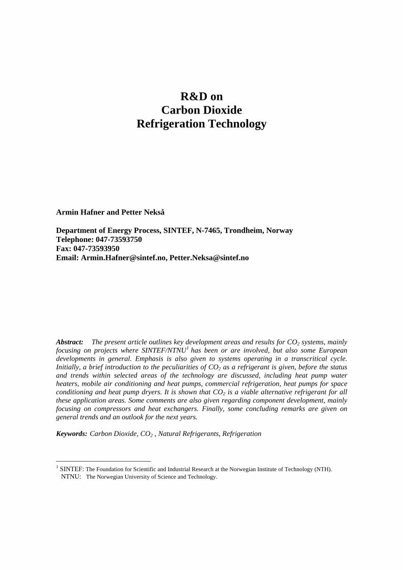
Figure 12 – Cost comparison of direct expansion HFC-404A system and state of the art all-CO2 system[36] Eggen and Aflekt reviewed the possibilities for CO2: i) as secondary refrigerant, ii) as a primary refrigerant in a low temperature stage in a cascade system, and iii) in all-CO2 centralised systems [2]. They also presented a prototype CO2/NH3 cascade system built in Norway. During the last years a considerable number of cascade systems has been installed in Europe, using CO2 in the low stage and different refrigerants in the high stage of the cascade. Advantages of CO2 cascade systems include the greatly reduced low-temperature compressor sizes, the absence of a liquid pump, and fewer stages of heat transfer. Several secondary fluid systems are also already operating in the Nordic countries, using CO2 as a volatile heat transfer fluid. The safety aspects and good thermophysical properties of CO2, leading to small pipe dimensions and good heat transfer, make it a preferable heat transfer fluid in indirect systems. The decentralised supermarket system described by Nekså, Girotto et al. uses CO2 as the only refrigerant. Self-contained display cabinets, each with CO2 refrigeration units, are connected to a hydronic heat recovery circuit that heats service water and buildings, see Figure 13 [14]. By utilizing the transcritical CO2 process, it is possible to have a large temperature glide in the hydronic circuit, typically 50-60 K, and a correspondingly low volume flow rate and small pipe dimensions. Waste heat with high temperature (70-75oC) is available for tap water and/or space heating. Excess heat is rejected to the ambient air by direct heat exchange. The system offers a very easy installation and gives the owner of the store a great flexibility in arranging and rearranging the cabinets. System simulations for a medium size supermarket have been carried out. Optimum hydronic supply and return temperatures to the cooling and freezing cabinets were identified. A comparison of the CO2 system and a conventional R-22 system with respect to the overall energy consumption of the supermarket for one year of
0
20
40
60
80
100
120
Mt Unit
LT U
nit
Conde
nser
Refrige
rant
Piping
Evapo
rators
(Extr
acos
t)Tota
l
CO2R404A
operation in a southern European climate was carried out. The CO2 system was found to reduce the energy consumption by 32% compared to the R-22 system. Figure 13 Decentralized CO2 supermarket refrigeration system with central heat recovery/heat rejection
Each CO2 unit can also be equipped with a condensing unit in order to reject heat directly to the shopping area when space heating is required. In the warm season with a heat surplus, the waste heat recovery circuit removes the heat. This concept reduces the power demand for the refrigeration units to the same level as for the baseline R-22 system, and the resulting overall energy consumption of the supermarket will then be further reduced. Also in light commercial equipment, CO2 may become an alternative to HFC refrigerants. The Coca Cola Company (TCCC) is evaluating alternative refrigerants to HFCs for light commercial refrigeration systems. SINTEF has participated in a group that has assisted TCCC in evaluating CO2 refrigeration systems based on Shecco Technology. TCCC has found CO2 to be the best option for their equipment:”CO2 based refrigeration is currently the best option for the global needs of Coca Cola’s sales and marketing equipment” [55]
Waste heatrejection system
Heat recovery (optional)
CO refrigeration
Cooler, -10 C
Freezer, -35 C
Auxiliarycooler
2
oo
o
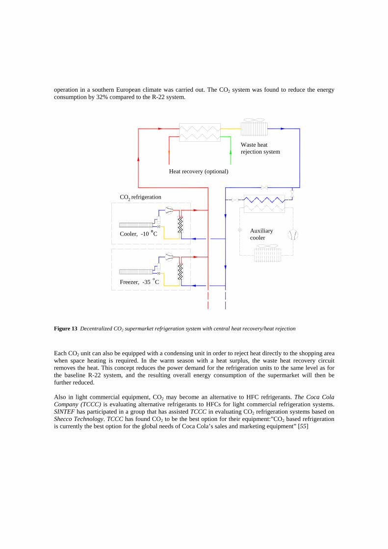
7 HEAT PUMPS FOR SPACE CONDITIONING Until now, most of the focus for CO2 heat pumps has been on tap water heating. The market for CO2 heat pumps would of course be extended significantly if the demand for space heating could be covered efficiently in addition to the demand for tap water heating. Schiefloe and Nekså investigated a system design as shown in Figure 14 [39, 40]. In order to achieve a lowest possible return temperature from the heating system, radiator and air heating are connected in series. Tap water is pre-heated in parallel with the space heating and heat exchange against hot discharge gas is used to achieve the required hot water temperature. In order to simplify the system design, the tap water heating part could also be implemented as a separate system or covered when space heating is not required.
Figure 14 System design for a combined space and water heating system. The process is also illustrated in the T-s diagram. A comparison with a system using HFC-134a as working fluid showed favourable seasonal performance for the CO2 system when more than 30% of the heating demand for space heating was demanded by the air heating system. The rest is then a demand of the radiator system. A 70/50oC radiator system and heat recovery efficiency of the balanced ventilation system of 60% was assumed. In larger buildings in Norway typically more than 50% of the heating demand is air heating and this percentage is increasing due to better insulation and increased air quality requirements. This indicates that CO2 may be a promising candidate for this application. Residential heat pumps for heating only are quite common in Europe, especially in the North, and in certain other areas in the world. Stene studied a residential brine to water CO2 heat pump for combined space heating and hot water heating [41]. He found that the seasonal performance factor of an integrated CO2 brine to water heat pump system was competitive to state of the art systems if the tap water heating demand constituted minimum 25% of the total annual heating demand and if the return temperature for the space heating system
Radiator
Air heater
AuxiliarySystem
CO Heat Pump System2
Space Heating
Evap
orat
o r
Ga s
Coo
ler
Wat
er H
eate
r HX
Hot
Wat
erSt
orag
e Ta
nk
EvaporationThrottling
Cooling
Distribution
Entropy, s
Tem
p era
ture
Com
pres
sion
Wate
r Hea
ting

was sufficiently low (30oC). It was also crucial to avoid heat transfer from hot to cold water in the storage tank. Rieberer, Halozan et. al. made detailed theoretical studies of controlled ventilation air heating systems with an integrated CO2 heat pump. The results looked very promising [42]. The overall system seasonal performance factor for a Graz, Austria climate was calculated to be in the range 6.15 to 6.5. This corresponds to a seasonal performance factor of the heat pump of above 4 (author's remark). Ground source heat is important as heat source for heat pumps in Europe. The brine systems frequently used may cause problems regarding polluting ground water if leakages occur. Both Univ. of Graz [43] and FKW in Hannover have developed earth probe systems with CO2. The probes are filled with CO2 and collecting heat from the ground by evaporation and rejecting heat in a cold head as heat source for a heat pump. The principle can be compared to that of a heat pipe. Very promising results has been reported, and the product is already commercialised. Several studies have investigated air-to-air reversible heat pumps with CO2 as refrigerant. This has been well summarised in [45]. In general it was found that the CO2 heat pumps compete with the HFC systems in heat pump mode, while air conditioning mode at high ambient temperatures lacked in efficiency. Even though the seasonal performance in cold climates may be superior for the CO2 systems already, these systems have not found the way to the market place yet. SINTEF is doing development work on an Asian/European type of split system, using a state of the art HFC-410A system as baseline. So far, the CO2 system performs better than the baseline system in heating mode, while lacking somewhat in efficiency in cooling mode. Heat exchangers better adapted to reversed cycle operation is expected to improve the system performance. 8 HEAT PUMP DRYERS Another interesting application is heat pump dryers. Based on theoretical considerations, Steimle reported that energy saving is possible due to better temperature adaptation in the heat exchangers, compared to subcritical processes [25]. It is also possible to achieve higher air temperatures without loss in efficiency, thus increasing the moisture extraction rate. Experimental results from Schmidt, Klöcker et al. report hp-COPs in the range 5.5 and 55% reduction in the energy consumption, including fan power, compared to a traditional electrically heated laundry dryer [24]. The results were achieved after a first optimisation of the prototype system, and it is hoped that further essential improvements still can be reached. Eikevik investigated CO2 heat pump dryers for food drying applications [46]. Very favourable efficiency figures for the system were reported. Also very important was the high degree of flexibility the system could offer, with a temperature range for the inlet of the drying chamber in the range of –30oC to +110oC. This is due to very favourable thermophysical properties of CO2 as working fluid in such systems. 9 COMPRESSORS The company Dorin, Italy, developed the first high-pressure semi-hermetic CO2 compressor series in the range of 1.7-10.7 m3/h swept volume. The series comprises single- and two-stage compressors with two cylinders, running at nominal speeds of 1450 and 2900 rpm (50Hz). This corresponds to cooling capacities in the range of 3-25 kW at –10oC evaporating temperature. A description and analysis of the pre-series one- and two-stage compressors can be found in Nekså, Dorin et al. [16,17]. Figure 15 shows a picture of the compressor, and measured overall isentropic and volumetric efficiency figures for medium sized compressors at that stage of development.

The single-stage machine reaches quite high efficiencies, especially at lower pressure ratios, representative for medium temperature refrigeration and upward. Two-stage figures are representative for the compressor operating in a system without throttling to medium pressure, indicating how it would perform in a single stage process compared to the single stage compressor. As the efficiency figures indicate, two-stage compression will give an advantage regarding energy efficiency in low temperature applications, typically for pressure ratios in the range of 6 to 9 when using CO2.
Figure 15 Compressor design and measured volumetric and isentropic efficiency for a single-stage and a two-
stage pre-series CO2 compressor with a swept volume of 2.7m3/h, as function of the pressure ratio, for high-pressures of 80, 95 and 110 bar. A constant suction gas superheat of 10oC was applied. For the two-stage compressor the intermediate pressure gas was cooled to 20oC.
The German company Bock developed a high-pressure, open-type compressor for transport applications. This development is described by Kaiser [9]. A semi-hermetic version of this compressor was introduced in 2002. Several compressors are developed or under development from a variety of companies. Omitting all the efficient compressors developed for mobile applications, it is important to mention the variety of hermetic compressors developed in Japan, primarily to serve for the heat pump water heater systems launched in the market. From an European perspective it may be important to mention development of small hermetic compressors from the company Danfoss, see Figure 16, and from the company Embraco. The German company Bitzer developed semi-hermetic CO2 Compressors (Octagon K Series), [51]. Bitzer is actively involved in a number of projects, for example are their compressors installed in a new Supermarket in Switzerland [52].
0.0
0.2
0.4
0.6
0.8
1.0
1 2 3 4 5 6 7 8 9 10p2/p1
λ
8095110
λ,
ηis
λ2-stage
ηis tot 2-stageηis tot

Figure 16 Danfoss hermetic CO2 compressor for maximum operating pressure 130 bar By introducing an expander, the thermodynamic losses in the CO2 cycle can be greatly reduced, thus improving the competitiveness even more, but also open application areas for which it so far has shown difficult to meet the efficiency requirements. Several European groups are working on expander concepts for CO2 systems, including the free-piston expander by Heyl [8] and the axial-piston machine by Heidelck [7]. Tøndell [54] describes small impulse type turbines for CO2 expansion. 10 HEAT EXCHANGERS AND HEAT TRANSFER Owing to the high operating pressure, CO2 heat exchangers generally use small-diameter tubing. Studies on compact air based heat exchangers for mobile and unitary applications have demonstrated the potential for compact and lightweight designs with high performance, especially when using extruded microchannel tubing, Figure 17 (Pettersen et al.) [53].
Figure 17 Principles of CO2 heat exchanger geometry using “multi-port” extruded tubes with microchannels,
folded fins, and a compact “double barrel” manifold. The heat exchanger is assembled by brazing in a furnace. From Pettersen et al [18].
Heat transfer tube
Manifold
Fin

Extensive studies have been conducted on heat transfer and pressure drop in microchannels, both covering supercritical-pressure cooled flow (Pettersen et al.) [20], and flow vaporization (Pettersen) [21]. Supercritical-pressure microchannel heat transfer is correlated well with well-known single-phase correlations, while flow vaporization is greatly influenced by nucleate boiling, dryout and post-dryout heat transfer and thus need more advanced correlations. Important contributions to understand these phenomena better can be found in [47], where also flow visualisation of vaporizing pure CO2 in a 1 mm heated glass tube are reported. Flow visualisation results of vaporizing CO2 with lubricant in the same test tube are reported in [48]. Two-phase flow distribution in heat exchanger manifolds is an important issue in microchannel heat exchangers. The potential drop in heat exchanger capacity could be more than 30% due to maldistribution of two-phase flow in the inlet manifold. This phenomenon was investigated in [49]. Figure 17 shows the flow maldistribution visualized in a glass manifold. CO2 and HFC-134a were used as refrigerants and a total of eleven manifold geometries were tested. The experimental data was compared to existing semi empirical models for phase split in T-junctions and a correlation for two-phase manifold flow split was developed.
Figure 17 Flow visualization of two-phase distribution in a glass manifold [49] Water/liquid based heat exchangers has also had a certain focus. Most attention has been paid to gascoolers for heat pump water heaters where counter-current flow conditions are required due to the large temperature glide, with emphasis on double-tube concepts.
11 CONCLUSION The revival of CO2 as a refrigerant started in Europe more than 17 years ago, and there has been a strong development of new technology worldwide using this refrigerant in several application areas since then. Developments which initially were driven primarily by environmental concerns have often resulted in disclosing additional advantages by using CO2, such as higher COP, higher cooling and heating capacity, better comfort, and added possibilities of heat recovery. Cost- and energy efficient systems have been developed and commercialised for some applications and more seems to come in the near future. With increasing focus on climate gas emission reductions, strict regulations on the use of HFC chemicals may be expected, possibly followed by phase-out targets and dates as announced by some European countries. These trends will clearly drive the interest in the direction of natural refrigerants in general and CO2 in particular.

REFERENCES [1] Callaghan, P. and Vainio, M., “EC poised for action on HFC134a in MACs: Results of MAC Summit
2003”, Earth Technology Forum, Motor Vehicle A/C Regulatory Innovations, Washington, April 23, 2003.
[2] Eggen, G. and Aflekt, K., “Commercial Refirgeration with Ammonia and CO2 as Working Fluids”, Natural Working Fluids '98, IIR - Gustav Lorentzen Conference on Natural Working Fluids, Oslo, Norway, IIR, June 2-5, 1998.
[3] Gentner H., “Passenger car air conditioning using carbon dioxide as refrigerant”. Proc. Natural Working Fluids’98, IIR-Gustav Lorentzen Conference on Natural Working Fluids, Oslo, Norway, June, 1998
[4] Hafner A. Pettersen J. Skaugen G. Nekså P., ”An Automobile HVAC System with CO2 as the Refrigerant”. IIR – Gustav Lorentzen Conference on Natural Working Fluids, Oslo, Norway, June 2-5, 1998.
[5] Hafner, A., “Experimental Study on Heat Pump Operation of Prototype CO2 Mobile Air Conditioning System”, 4th IIR-Gustav Lorentzen Conference on Natural Working Fluids, Purdue, USA, July 25-28, 2000.
[6] Hammer, H., and Wertenbach, J., “Carbon dioxide (R-744) as supplementary heating device”. 2000 SAE Automotive Alternate Refrigerants Systems Symposium, July 11-13, 2000, Scottsdale, Arizona.
[7] Heidelck, R.,” Expansionsmaschinen auf der basis modifizierter Hubkolbenmaschinen”. Ki Luft- und Kältetechnik, Vol 37, No 3, pp. 114-117, 2001.
[8] Heyl, P., “Untersuchungen transkritischer CO2-Prozesse mit arbeitsleistender Entspannung - Prozeßberechnungen, Auslegung und Test einer Expansions-Kompressions-Maschine”. Dissertation, Institute of Refrigeration and Cryogenics, TU Dresden, 1999.
[9] Kaiser, H., “Verdichter fur naturliche Kaltemittel in Nutzfahrzeugen und Omnibussen”. Ki Luft- und Kaltetechnik, No 8, 1996.
[10] Köhler, J., “Update – Second year of CO2 air conditioning operation on German city bus”. SAE Automotive Alternate Refrigerants Symposium, June 28 – July 1, Scottsdale, Arizona, 1999.
[11] Lorentzen, G., and Pettersen J., “New Possibilities for Non-CFC Refrigeration”. Proceedings from International Symposium on Refrigeration, Energy and Environment, Trondheim, pp. 147-163, June 1992.
[12] Mager, R., Hammer, H., Wertenbach, J., “Comparative Study on AC and HP-systems using the Refrigerants R-134a and R-744”, VDA Alternate Refrigerant Wintermeeting, Saalfelden, Austria, January 30-31, 2002.
[13] Mager, R et al, “New Technology: CO2 (R-744) as an Alternative Refrigerant”, MAC Summit 2003, Brussels, 10/11 02. 2003.
[14] Nekså, P., Girotto, S. and Schiefloe, P. A., “Commercial Refrigeration Using CO2 as Refrigerant - System Design and Experimental Results”. IIR - Gustav Lorentzen Conference on Natural Working Fluids, Oslo, Norway, IIR, June 2-5, 1998.
[15] Nekså, P., Rekstad, H., Zakeri, G. R. and Schiefloe, P. A., “CO2-Heat Pump Water Heater: Characteristics, System Design and Experimental Results”, Int. Journal of Refrigeration 21: 172-179, 1998.
[16] Nekså, P., Dorin, F., Rekstad, H., Bredesen, A.M., Serbisse, A., “Development of Semi-Hermetic CO2-Compressors”, 20th International Congress of Refrigeration, IIR/IIF, Sydney, 1999.
[17] Nekså, P., Dorin, F., Rekstad, H. and Bredesen, A.M., “Development of two-stage semi-hermetic CO2-compressors”, 4th IIR-Gustav Lorentzen Conference on Natural Working Fluids, Purdue, USA, July 25-28, 2000.
[18] Parsch, W., “Status of Compressor Development for R-744 Systems”, VDA Alternate Refrigerant Wintermeeting, Saalfelden, Austria, January 30-31, 2002.

[19] Pettersen, J., “Comparison of explosion energies in residential air-conditioning systems based on HCFC-22 and CO2”, 20th International Congress of Refrigeration (IIR), Sydney, Australia, September 19-24, 1999.
[20] Pettersen, J., Rieberer, R., Munkejord, S.T., ”Heat Transfer and Pressure Drop for flow of Supercritical and Subcritical CO2 in Microchannel Tubes. Final Technical Report. US Army, European Research Office, Contract N-68171-99-M-5674. Report issued by SINTEF Energy Research and Norwegian University of Science and Technology, February 2000.
[21] Pettersen, J., “Flow Vaporization in Microchannel Tubes”, Dr.techn. thesis, Faculty of Engineering Science and Technology, NTNU, February 2002.
[22] Schwartz, “Forecasting R-134a emissions from car air conditioning systems until 2020 in Germany”, translation of lecture at DKV Deutsche Kaelte-Klima-Tagung, Bremen, 22.-24. November 2000, http://www.oekorecherche.de/english/ac-2000.html
[23] Schwartz, W, “R-134a Emissions from Passenger Car Air Conditioning Systems”, VDA Alternate Refrigerant Wintermeeting, Saalfelden, Austria, January 30-31, 2002.
[24] Schmidt, E. L., Klöcker, K. and Flacke, N., “Heat Pumps for Dehumidification and Drying Processes in Residential and Commercial Applications. - Hot Air Drying Heat Pump using a Transcritical CO2 Process” - CO2 Technology in Refrigeration, Heat Pump and Air Conditioning Systems, Mainz, Germany, 1999.
[25] Steimle, F., “CO2-Drying Heat Pumps. CO2 Technology in Refrigeration, Heat Pump & Air Conditioning Systems”, Trondheim, Norway, IEA Heat Pump Program, May 13-14, 1997.
[26] Adriansyah, W., “Combined Air-conditioning and Tap Water Heating Plant, Using CO2 as Refrigerant for Indonesian Climate Condition”, Dr.ing (PhD) thesis no. 2001:54, Norwegian University of Science and Technology, 2001.
[27] Zakeri, G.R., Nekså, P., Rekstad, H., Lang-Ree, K and Olsen, T.: Results and experiences with the first commercial pilot plant CO2 heat pump water heater, 4th IIR-Gustav Lorentzen Conference on Natural Working Fluids, Purdue, USA, July 25-28, 2000.
[28] Nekså, P.: CO2 Heat Pumps for the Building Sector, Cold Climate HVAC 2003, Trondheim, June 15-18, 2003.
[29] UTC (2003): http://www.utc.com/investors/2003-09-4_techday/heat_pump.pdf [30] Adriansyah, W.: Development of combined air conditioning and tap water heating CO2 test rig in
Indonesia-Preliminary results, International Conference on Fluid and Thermal Energy Conversion 2003, FTEC 2003,Bali, Indonesia, December 7 – 11, 2003.
[31] Hrnjak, P.: Design and performance of improved R744 system based on 2002 technology, , SAE Automotive Alternate Refrigerant Systems Symposium, Scottsdale AZ, July, 2003.
[32] Pettersen, J. and Nekså, P.: Consequences of the Newest Improvements in R-744 Systems, SAE Automotive Alternate Refrigerant Systems Symposium, Scottsdale AZ, July, 2003.
[33] www.poa-project.com [34] Hafner, A.: Compact interior heat exchangers for CO2 mobile heat pumping system, Dr.ing (PhD) thesis
no. 2003:05, Norwegian University of Science and Technology, 2003. [35] Nekså, P. and Girotto, S.: CO2 as Refrigerant within Commercial Refrigeration, Theoretical Considerations
and Experimental results, 5th IIR - Gustav Lorentzen Conference on Natural Working Fluids, September 17-20, Guangzhou, China , 2002.
[36] Girotto, S., Minetto, S. and Nekså, P.: Commercial Refrigeration with CO2 as Refrigerant, Experimental Results, XXI IIR Int. Congress of Refrigeration, Washington, August 17-22, 2003.
[37] IPCC/TEAP Special Report: Safeguarding the ozone layer and the global climate system: Issues related to hydrofluorocarbons and perfluorocarbons. In print, see www.ipcc.ch.
[38] Veiby O.J.: Internal records/documentation in the ICA supermarket chain in Norway, Oslo, Norway, 2003. [39] Schifloe, P.A. and Nekså, P.: CO2 varmepumpe for bygningsoppvarming, forprosjekt (in Norwegian),
SINTEF Report TR F4875, Trondheim, Norway, 1999. [40] Nekså, P. (2002): CO2 Heat Pumps, International Journal of Refrigeration, Vol 25, Issue 4, June 2002, p
421-427.

[41] Stene J.: Residential brine to water CO2 heat pump for combined space heating and hot water heating, Dr.ing (PhD) thesis to be published, Norwegian University of Science and Technology, 2004.
[42] Rieberer, R. and Halozan, H.: CO2 heat pumps in controlled ventilation systems, Proceedings of the third IIR- Gustav Lorentzen conference on Natural Working Fluids, Oslo, Norway, 1998, p. 212-222.
[43] Halozan, H., Rieberer, R. et al.: Direct expansion ground coupled heat pumps, Proceedings of the 21st IIR Int. Congress of Refrigeration, Washington, 2003.
[44] Stadtlander, C.: Personal communication, January, 2004. [45] Kim, M.H., Pettersen, J. and Bullard, C.: Fundamental process and system design issues in CO2 vapor
compressin systems, Progr. in Energy and Combustion Science, in press, 2004. [46] Eikevik, T.M., Alves-Filho, O. and Strømmen, I.: Carbon Dioxide Heat Pump an Measurement on
Coefficient of Performance and Specific Moisture Extraction Ratio, 2nd Nordic Drying Conference, Copenhagen, June 25-27, 2003.
[47] Pettersen, J.: Flow vaporization of CO2 in microchannel tubes, Dr. technicae thesis KKT-rapport 2002:1, Norwegian University of Science and Technology, 2002.
[48] Argento, A.: Influence of lubricant in flow vaporization of CO2 in microchannel tubes, Diploma work no 03/65, FH Kalshruhe in cooperation with SINTEF, Trondheim, December, 2003.
[49] Vist, S.: Two-phase flow distribution in heat exchanger manifolds, Dr.ing (PhD) thesis to be published, Norwegian University of Science and Technology, 2004.
[50] McFarland M.: Proceedings of the Next Generation Mobile AC Workshop India, New Delhi, March 2005.
[51] www.bitzer.de [52] Haaf, S., Heinbokel, B. und Gernemann A. : Erste CO2 –Kälteanlage für Normal- und Tiefkühlung in
einem Schweizer Hypermarkt. Kälte & Klimatechnick. Nr. 2 , 2005. [53] Pettersen, J., Hafner, A., Skaugen, G. and Rekstad, H, “Development of Compact Heat Exchangers for
CO2 Air Conditioning Systems”, International Journal of Refrigeration, Vol 21, No 3, pp. 180-193, 1998 [54] Tøndell, E., Bredesen, A.M., Pettersen, J. and Nekså, P.: Test facility and concept for CO2 expander.
Proceedings of the 6th Gustav Lorentzen Natural Working Fluids Conference, Glasgow, UK 2004. [55] Refrigerants Naturally, Brussels, June 2004. See: www.refrigerantsnaturally.com