rainwater harvesting capstone project
TRANSCRIPT
CENE 476: Capstone Prep
Page 1
RAINWATER HARVESTING
CAPSTONE PROJECT
NAME: HAYLIE BREWER, ERICA KIESOW, AND BRETT HIGHTOWER
CLASS SESSION: SECTION 1: 9:35-10:50
GRADING INSTRUCTOR: ALARICK REIBOLDT, EIT, MENG, LECTURER
DATE: MAY 10TH, 2016
CENE 476: Capstone Prep
Page 2
TABLE OF CONTENTS 1.0 PROJECT PURPOSE ............................................................................................................................ 3
2.0 PROJECT BACKGROUND ...................................................................................................................... 3
3.0 TECHNICAL CONSIDERATIONS .............................................................................................................. 4
3.1 CISTERN DESIGN .............................................................................................................................. 4
3.2 PUMP SELECTION SPECIFICATIONS ................................................................................................. 5
3.3 DETERMINATION AND DELINEATION OF CATCHMENT AREA ......................................................... 5
3.4 IRRIGATION DISTRIBUTION ANALYSIS ............................................................................................. 5
3.5 GEOTECHNICAL ASPECTS ................................................................................................................ 5
4.0 POTENTIAL CHALLENGES ....................................................................................................................... 5
5.0 STAKEHOLDERS .................................................................................................................................... 5
6.0 SCOPE OF SERVICES................................................................................................................................. 6
TASK 1.0 FIELD EVALUATION .................................................................................................................... 6
TASK 2.0 DESIGN STANDARDS, SPECIFICATIONS, AND CODES ................................................................. 6
TASK 3.0 DESIGN: CATCHMENT SYSTEM .................................................................................................. 7
TASK 4.0 DESIGN: CISTERN ........................................................................................................................ 7
TASK 5.0: DESIGN: BATHROOM DISTRIBUTION ........................................................................................ 8
TASK 6.0: DESIGN: IRRIGATION DISTRIBUTION ......................................................................................... 8
TASK 7.0: PROJECT SCHEDULE .................................................................................................................. 9
TASK 8.0: STAFFING AND PROJECT COST .................................................................................................. 9
TASK 9.0: PROJECT MANAGEMENT ........................................................... Error! Bookmark not defined.
7.0 APPENDIX .............................................................................................................................................. 13
7.1 APPENDIX A: ROOF FRAMING PLAN FOR GARAGE/DECKS ............................................................ 13
7.2 APPENDIX B: CROSS SECTION OF GARAGE/DECKS ........................................................................ 14
7.3 APPENDIX C: FLOOR & ELECTRICAL PLAN FOR GARAGE/DECKS .................................................... 15
7.4 APPENDIX D: DECK FRAMING PLAN .............................................................................................. 16
CENE 476: Capstone Prep
Page 3
1.0 PROJECT PURPOSE The purpose of this project is to design and implement a rainwater harvesting catchment system for the client’s property in Flagstaff, Arizona. The stored water will be used to irrigate the client’s vegetable garden, and to supply toilet flushing water. By utilizing harvested rainwater to supply toilet flushing and irrigation, the client will save money and will reduce overall non-potable water usage from the Kachina Village Improvement District supply.
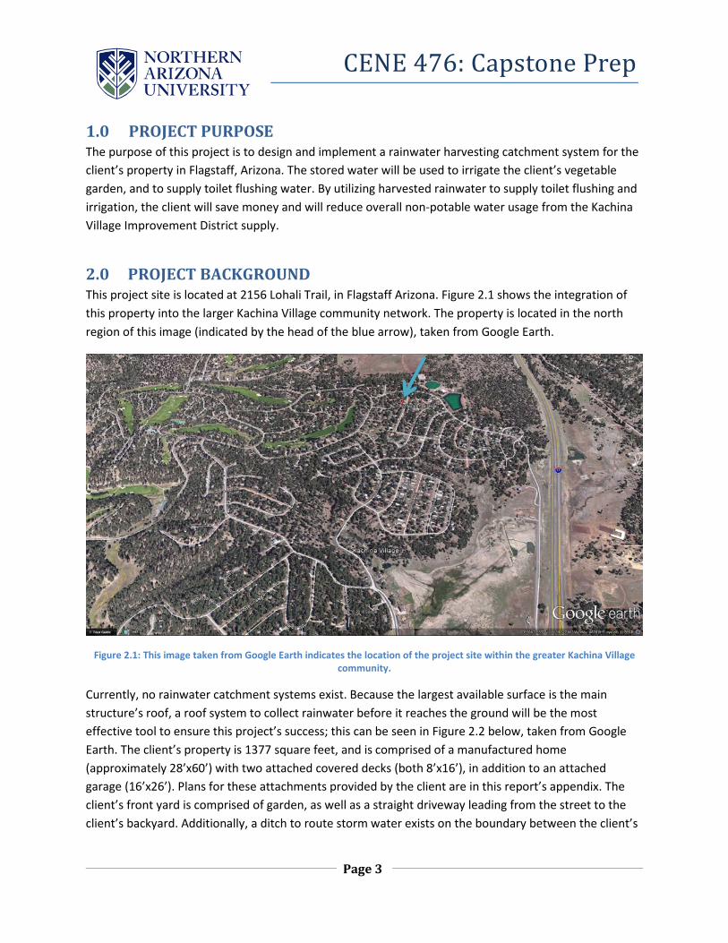
2.0 PROJECT BACKGROUND This project site is located at 2156 Lohali Trail, in Flagstaff Arizona. Figure 2.1 shows the integration of this property into the larger Kachina Village community network. The property is located in the north region of this image (indicated by the head of the blue arrow), taken from Google Earth.
Figure 2.1: This image taken from Google Earth indicates the location of the project site within the greater Kachina Village community.
Currently, no rainwater catchment systems exist. Because the largest available surface is the main structure’s roof, a roof system to collect rainwater before it reaches the ground will be the most effective tool to ensure this project’s success; this can be seen in Figure 2.2 below, taken from Google Earth. The client’s property is 1377 square feet, and is comprised of a manufactured home (approximately 28’x60’) with two attached covered decks (both 8’x16’), in addition to an attached garage (16’x26’). Plans for these attachments provided by the client are in this report’s appendix. The client’s front yard is comprised of garden, as well as a straight driveway leading from the street to the client’s backyard. Additionally, a ditch to route storm water exists on the boundary between the client’s

CENE 476: Capstone Prep
Page 4
property and the street, which is connected to the neighboring properties via single culverts, seen in Figure 2.2 below. A site visit will develop a greater understanding of the site’s current conditions.
Figure 2.2 – This figure shows the site’s previous conditions. The property boundaries are shown by the gates on either side of the yard. An updated photo will be included after the initial site visit occurs.
3.0 TECHNICAL CONSIDERATIONS There are various components of rainwater harvesting collection and distribution systems that must be taken into consideration. The components that will involve engineering judgement and technical considerations are as listed throughout this section.
3.1 CISTERN DESIGN The cistern will be the main component of the design, because it will be used as primary storage for distribution system. The construction material of the cistern will be constrained by the client’s budget. Fiber glass, reinforced concrete, and steel are common materials used to construct cisterns. A concrete slab foundation may be required based on the selected cistern material. Due to area and freezing weather condition constraints, the cistern will have to be under the client’s driveway. A structural analysis will be required to ensure the cistern design can withstand maximum expected water, soil, and vehicle load. A geotechnical analysis of the type of soil will be considered to ensure the cistern does not sink or crack. Sizing the cistern will require a combined demand for both irrigation and toilet use.
CENE 476: Capstone Prep
Page 5
3.2 PUMP SELECTION SPECIFICATIONS The pump design will focus on providing sufficient pressure head to redirect the water from underground. Pump selection will require a knowledge of required power, flow, pressure head, and properties of the water in the system (temperature, viscosity). Pumps will be responsible for supplying adequate flow to both the irrigation and toilet systems at varying time durations, demands, and pressure heads.
3.3 DETERMINATION AND DELINEATION OF CATCHMENT AREA The slope and area of the roof will be two main factors during the rainwater collection analysis. The runoff precipitation route will be important in determining the length of gutters, and where they should be placed. The amount of precipitation the roof can hold at maximum capacity will also provide an estimation of how much can be collected. Local rain gage data will provide estimates as to how much water will be supplied to the system.
3.4 IRRIGATION DISTRIBUTION ANALYSIS Since the cistern is underground, the irrigation water will have to be distributed by a gravitational or pressurized system. There must be sufficient head for the water to be distributed from the tank to the garden. This analysis will involve flow and hydraulic head calculations.
3.5 GEOTECHNICAL ASPECTS Due to underground placement of the cistern, the team should consider a soil analysis of the site. Because the client stated the tank’s location is below a driveway surface to reduce risk of water contamination and freezing in winter temperatures, drainage behavior of the site should be understood to evaluate soil bearing capacity, as well as the influence of water on the proposed cistern.
4.0 POTENTIAL CHALLENGES Potential challenges can arise during the design process. It is important to address these issues to avoid surprises as the project progresses. A main potential challenge is ensuring that the final design follows codes, regulations, and standards set by Coconino County. The county may have limits on how much and how often rainwater can collected. The time during the year in which rain harvesting is permitted will also be taken into account, as the system’s success is dependent on the amount of water being precipitated in the area. The two main constraints on this project are budget and time. The amount of money available for the project will allow the team to select materials necessary for the design, and will affect the amount of time allotted to the company hired for construction. Moving forward with the project will require strict adherence to a schedule, which will be developed in future deliverables.
5.0 STAKEHOLDERS The stakeholders are those who can be potentially affected by this project. This includes anyone involved before and after design implementation. These people are affected by the overall outcome of

CENE 476: Capstone Prep
Page 6
this project. These people are the following: ALARICK REIBOLDT, CLIENT/STAKEHOLDER As the client, Lar Reiboldt, is the end user of the rainwater harvesting system. He will be using the final cistern design to irrigate his garden and provide a bathroom water source. The overall design takes into consideration criteria specified by the standards set by the client. COCONINO COUNTY COMMUNITY, STAKEHOLDER The Coconino County community as a whole is a stakeholder, because the municipality can be potentially affected by the rainwater harvesting process. When rainwater is prevented from recharging the Coconino aquifer, county businesses and residents are not able to access that removed water. The volume of water being taken out of the hydrologic system will not have significant impacts on the available water demand for the public or environment. HAYLIE BREWER, BRETT HIGHTOWER, ERICA KIESOW, STAKEHOLDERS The Spring 2016 CENE476/486 capstone team is responsible for delivering a completed design. Depending on the success of the project, the team’s reputation as future engineers is at stake.
6.0 SCOPE OF SERVICES The purpose of this section is to list and detail the tasks necessary to complete this project. Any work to be done not explicitly stated as a task within this section will not be completed by the team. (Refer to exceptions below
TASK 1.0 FIELD EVALUATION TASK 1.1 SITE EVALUATION: GENERAL INSPECTION
Overall site inspection is to occur to gain understanding of existing structure and general site area conditions. This will allow the team to fully assess and evaluate the environment in which the design will inhabit. The main components of this evaluation are the tasks listed below.
TASK 1.2 SITE EVALUATION: STRUCTURAL This evaluation will be limited to a visual inspection. This is to ensure that the house is properly intact, and is capable of upholding any design components applicable to this project.
TASK 2.0 DESIGN STANDARDS, SPECIFICATIONS, AND CODES The Coconino County design standards, specifications, and codes will be used to determine the legal limitations and constraints during the design process. In the event that county guidelines do not satisfy the design specifications, the City of Flagstaff Title 13 will be used for design recommendations.

CENE 476: Capstone Prep
Page 7
TASK 3.0 DESIGN: CATCHMENT SYSTEM TASK 3.1: ROOF RUNOFF
Precipitation data from NOAA will be used to determine the demand criteria. The house construction plans provided in Section 7.0 of this report will be used to calculate the drainage area, and runoff routes.
TASK 3.2: GUTTER COLLECTION SYSTEM DESIGN This design will include the selection of required materials, in addition to dimensions and layout of the system. The team will not be responsible for the physical design of the gutter system. A list of potential manufacturers of a specified gutter type will be provided within the design phase of this project.
TASK 3.3: CONVEYANCE SYSTEM DESIGN This design will include the required pipe material, dimensions, and layout to meet design criteria. Connections will be selected for the system based on budget constraints and necessary redirection of flow to provide cistern demand.
TASK 3.4: FIRST FLUSH/DISINFECTION SYSTEM DESIGN The team will first take into consideration a pre-existing first flush product design by a manufacturer. If a pre-existing first flush design does not meet the constraints and criteria of the project, the team will produce a design to fulfill these requirements; in the event of this occurring, the following components are to be selected by the team: size, connections, materials, and placement of the first flush system.
TASK 4.0 DESIGN: CISTERN TASK 4.1: CAPACITY
This will include the approximated peak demand based on current data available. The capacity of the cistern will be dictated by the runoff data from NOAA as of 2016, and available space.
TASK 4.2: LOCATION The client has specified the location of where the cistern should be constructed. The codes will provide an appropriate offset distance from the property line in order to meet county regulations. City of Flagstaff codes will also be used to determine the amount of cover the cistern should be designed for.
TASK 4.3: CONSTRUCTION MATERIAL SPECIFICATIONS Construction material will be based on the available budget, and design constraints. A braced frame design to cover the cistern, and concrete foundation analysis may be necessary based on the construction material chosen.

CENE 476: Capstone Prep
Page 8
TASK 4.4: DISINFECTION Disinfection and sanitation methods will be taken into consideration during the design process to avoid water contamination. This will also prevent potential public safety hazards.
TASK 4.5 SITE EVALUATION: GEOTECHNICAL Soil samples should be collected in order for the following purposes: testing will include a sieve and moisture content analysis. The soil will be classified using AASHTO and USCS testing methods. The AASHTO test will be limited to an Atterberg limits analysis. A consolidation test will be conducted to estimate settlement of soil under an applied load. The soil’s bearing capacity will be calculated using the unit weight of soil. Collected samples will be limited to 0.15 cubic feet of existing soil, or the equivalency of 1 US gallon. Depending on determined soil characteristics through testing, the team will decide if further tests need to be conducted.
TASK 5.0: DESIGN: BATHROOM DISTRIBUTION TASK 5.1: DISTRIBUTION DESIGN
This design will be limited to the selection of required pipe material and connections, dimensioning, and layout to meet design criteria.
TASK 5.2: PUMP SELECTION AND SPECIFICATION This design will be limited to the determination of specifications required to select a suitable pump for this application. Specifications include total required head, flow demand, allowable and required net positive suction head, efficiency, impeller size, and required horsepower for operation.
TASK 5.3: STORAGE TANK This design of this system is limited to selection of the required construction material, dimensions, and layout to meet design criteria. Insulation for the tank will be determined based off of climate conditions.
TASK 5.4: CONSTRUCTION MATERIAL Construction material will be based on the available budget, and design constraints.
TASK 6.0: DESIGN: IRRIGATION DISTRIBUTION TASK 6.1: PIPE DESIGN
This design of this system is limited to the selection of required construction material, dimensions, and layout to meet flow criteria and available demand.
TASK 6.2: PUMP SELECTION AND SPECIFICATION This design will be limited to the determination of specifications required to select a suitable pump for this application. Specifications include total required head, flow demand, allowable and required net positive suction head, efficiency, impeller size, and required horsepower for operation.

CENE 476: Capstone Prep
Page 9
TASK 6.3: DISTRIBUTION SYSTEM The client has specified that a garden hose is the preferred choice of irrigation distribution. The team will not be responsible for providing a hose design. A garden hose will be selected based on local availability and budget constraints, unless the client specifies otherwise.
TASK 7.0: PROJECT MANAGEMENT TASK 7.1: CLIENT, TECHNICAL ADVISOR, AND TEAM MEETINGS TASK 7.2: 50% REPORT TASK 7.3: 90% REPORT TASK 7.4: FINAL PROPOSAL
TASK 7.5: FINAL PRESENTIATION TASK 7.6: WEBSITE
7.0: PROJECT SCHEDULE The project schedule is located in Appendix E of this report. This document outlines the time progression of this project. It includes important due dates, milestones, and the tasks listed in Section 6.0 Scope of Services of this report. It details when and how long each task will take to be completed. The design work for this project will start in the beginning of September 2016, and end in December 2016.
8.0: STAFFING AND PROJECT COST Classifications and codes are used to identify the staff who are assigned on this project. Table 1 shows the corresponding code for each staff member assigned to this project. A staff Senior Engineer is responsible for the oversight and project management. The Engineer II will be responsible for more advanced aspects of design components, and is capable of applying previous work knowledge and experience to this project. This personnel plans the overall completion of various tasks, and oversees Engineer I. The Engineer I is an accredited engineer in training (EIT) and is responsible for a majority of the basic concepts and techniques involved in the design process. The Geotechnical Technician conducts tests in the lab, and is responsible for the soil tests for this project. The Administrative Assistant is responsible for bookkeeping, correspondence, and the documenting all deliverables. Table 2 applies these job descriptions to the corresponding tasks associated with this project. It is based on an hourly breakdown on how time is allocated for each staff member.

CENE 476: Capstone Prep
Page 10
Table 1: Staff Classification and Code
Classification Code
Senior Engineer SENG Engineer II ENG II
Engineer I ENG I
Geotechnical Technician GTECH
Administrative Assistant AA
Table 2: Hourly Design Projection
1.0 Field Evaluation 1.1 Site Inspection
2 8
2.0 Design Standards, Specs, Codes
Research Coconino
County Codes
3 16
3.0 Design Catchment System
Roof Runoff 1 6
Gutter Collection
System Design
8 12
Conveyance System Design
8 10
First Flush/ Disinfection
System Design
7 15
4.0 Cistern Design Capacity 3 10 Location 3 6
Construction
Material Specifications
8 10
Disinfection
4 12
Geotechnical
Evaluation
8
Slab Design 10 30
CENE 476: Capstone Prep
Page 11
5.0 Bathroom Distribution Design
Distribution Design
10 20
Pump Selection and Specification
2 6
Storage Tank
10 20
Construction Material
Specifications
4 8
6.0 Irrigation Distribution Design
Pump Selection and Specification
2 6
Pipe Design 8 10 Distribution
System 2 4
7.0 Project Management
7.1 Meetings 5 10 20 3 5
7.2 50% Report
2 4 15 2 10
7.3 90% Report
2 4 15 10
7.4 Final Proposal
2 4 3 5
7.5 Final Presentation
2 2 3
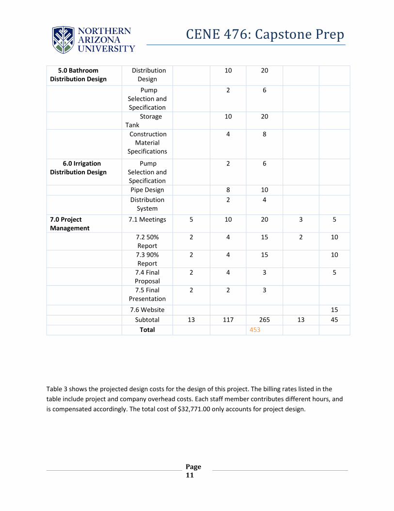
7.6 Website 15 Subtotal 13 117 265 13 45
Total
453
Table 3 shows the projected design costs for the design of this project. The billing rates listed in the table include project and company overhead costs. Each staff member contributes different hours, and is compensated accordingly. The total cost of $32,771.00 only accounts for project design.

CENE 476: Capstone Prep
Page 12
Table 3: Projected Design Costs
Classification Hours Billing Rate, $/hr
Cost, $
SENG 13 $ 170.00 $ 2,210.00
ENG II 117 $ 100.00 $ 11,700.00
ENG I 265 $ 65.00 $ 17,225.00
GTECH 13 $ 22.00 $ 286.00
AA 45 $ 30.00 $ 1,350.00
TOTAL $32,771.00

CENE 476: Capstone Prep
Page 13
9.0 APPENDIX 7.1 APPENDIX A: ROOF FRAMING PLAN FOR GARAGE/DECKS

CENE 476: Capstone Prep
Page 14
7.2 APPENDIX B: CROSS SECTION OF GARAGE/DECKS
CENE 476: Capstone Prep
Page 15
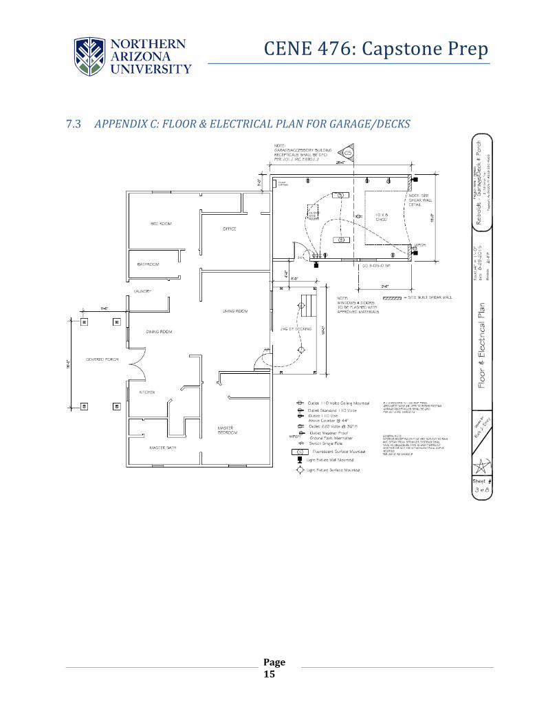
7.3 APPENDIX C: FLOOR & ELECTRICAL PLAN FOR GARAGE/DECKS

CENE 476: Capstone Prep
Page 16
7.4 APPENDIX D: DECK FRAMING PLAN