rain/freeze sensor, model twrfs rain sensor, model twrs and ... - toro · i introduction the toro...
TRANSCRIPT
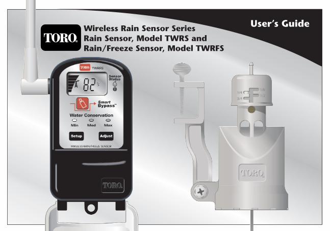
Wireless Rain Sensor SeriesRain Sensor, Model TWRS andRain/Freeze Sensor, Model TWRFS
User’s Guide
RainSensorAlpha7 3/10/2005 3:31 PM Page I
i
IntroductionThe Toro Wireless RainSensor system, model TWRS for rain sensing and TWRFS for rain and freezesensing, is a powerful water conservation and management tool that connects your automaticirrigation system to actual environmental factors vital to the health and maintenance of yourlandscape. Without sensor input, the controller simply turns the sprinklers on and off based on aroutine irrigation schedule. Linking controller operation to real-time rain and/or freeze conditionseliminates unnecessary irrigation and dramatically reduces resource consumption–all withoutcompromising the health and beauty of your landscape. And–it’s wireless. No cable to run or holes todrill. Simple installation and setup delivers reliable, intelligent sensor control in a matter of minutes.
Contents PageGetting Started . . . . . . . . . . . . . . . . . . . . . . . . . . . 1Receiver Module Features . . . . . . . . . . . . . . . . . . 4Installing the Receiver Module . . . . . . . . . . . . . . 5Initial Sensor System Test. . . . . . . . . . . . . . . . . . . 8Sensor Module Features . . . . . . . . . . . . . . . . . . . . 9Installing the Sensor Module . . . . . . . . . . . . . . . 10Freeze Sensor Site Selection. . . . . . . . . . . . . . . . 13Set Temperature Activation Threshold. . . . . . . . 14Water Conservation Feature . . . . . . . . . . . . . . . . 15Smart Bypass Feature . . . . . . . . . . . . . . . . . . . . . 16Water Delay Feature . . . . . . . . . . . . . . . . . . . . . . 16
Signal Strength Display Feature. . . . . . . . . . . . . 17Battery Strength Display Feature . . . . . . . . . . . . 17Dry Out Feature . . . . . . . . . . . . . . . . . . . . . . . . . 18Fail Safe Feature . . . . . . . . . . . . . . . . . . . . . . . . . 18Turn Receiver Module Off and On . . . . . . . . . . 20Set or Restore the Sensor Address Code . . . . . . 20Sensor Module Battery Replacement. . . . . . . . . 21Troubleshooting . . . . . . . . . . . . . . . . . . . . . . . . . 22Specifications . . . . . . . . . . . . . . . . . . . . . . . . . . . 24Warranty Information . . . . . . . . . . . . . . . . . . . . . 25Electromagnetic Compatibility. . . . . . . . . . . . . . 26
RainSensorAlpha7 3/10/2005 3:31 PM Page II
1
The wireless sensor system is comprised of a programmable, weather-resistant receiver moduleand a sensor module with built-in transmitter. The receiver installs next to the irrigation controllerand connects to the controller’s 24 Vac power source and sensor input terminals (if equipped) or splices directly into the irrigation valve common wire. The sensor module is installed withinrange of the receiver in a location that best represents the landscape’s sun/shade exposure and can provide reliable communication from the sensor to the receiver.Once activated by preset rain or low temperature levels (Rain/Freeze model only), the sensorcommunicates to the receiver via ultra high-frequency radio signal. The receiver responds byplacing the controller’s automatic watering schedule on hold or by simply opening the valvecommon circuit to prevent sprinkler valve operation. When watering is once again needed, the sensor system automatically resets, allowing automatic irrigation to resume. More than just an accurate rain switch, the wireless sensor system actually adapts to yourlandscape with the simple, yet sophisticated Water Conservation feature. Just choose theconservation level that corresponds to your landscape soil type and the sensor location. A dry-out period, adjusted for actual rainfall duration, is automatically placed after the sensorsystem resets to effectively delay automatic watering until it is actually needed.Other standard features include a Smart BypassTM button that gives you manual control over thesensor system with a single touch, system status indicators to see at glance that your sensorsystem is active and watering is on hold, watering delay to postpone automatic watering from 1 to 5 days, air temperature displayed for Rain/Freeze sensors and even a Fail-safe mode to allowirrigation in case the sensor system is not performing properly.
RainSensorAlpha7 3/10/2005 3:31 PM Page 1
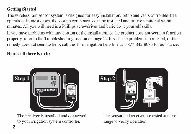
Getting StartedThe wireless rain sensor system is designed for easy installation, setup and years of trouble-freeoperation. In most cases, the system components can be installed and fully operational withinminutes. All you will need is a Phillips screwdriver and basic do-it-yourself skills.If you have problems with any portion of the installation, or the product does not seem to functionproperly, refer to the Troubleshooting section on page 22 first. If the problem is not listed, or theremedy does not seem to help, call the Toro Irrigation help line at 1-877-345-8676 for assistance.
Here’s all there is to it:
2
The receiver is installed and connectedto your irrigation system controller.
Step 1
The sensor and receiver are tested at closerange to verify operation.
Step 2
RainSensorAlpha7 3/10/2005 3:31 PM Page 2
3
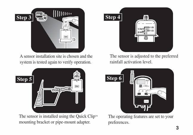
The sensor is adjusted to the preferredrainfall activation level.
The sensor is installed using the Quick ClipTM
mounting bracket or pipe-mount adapter.The operating features are set to yourpreferences.
A sensor installation site is chosen and thesystem is tested again to verify operation.
Step 5
Step 4
Step 6
Step 3
RainSensorAlpha7 3/10/2005 3:31 PM Page 3
4
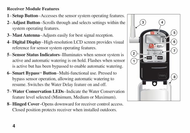
Receiver Module Features
1– Setup Button–Accesses the sensor system operating features.
2– Adjust Button–Scrolls through and selects settings within thesystem operating features.
3– Mast Antenna–Adjusts easily for best signal reception.
4– Digital Display–High-resolution LCD screen provides visualreference for sensor system operating features.
5– Sensor Status Indicators–Illuminates when sensor system isactive and automatic watering is on hold. Flashes when sensoris active but has been bypassed to enable automatic watering.
6– Smart BypassTM Button–Multi-functional use. Pressed tobypass sensor operation, allowing automatic watering toresume. Switches the Water Delay feature on and off.
7– Water Conservation LEDs–Indicate the Water Conservationfeature level selected (Minimum, Medium or Maximum).
8– Hinged Cover–Opens downward for receiver control access. Closed position protects receiver when installed outdoors.
3 4
5
6
7
8
1
2
RainSensorAlpha7 3/10/2005 3:31 PM Page 4
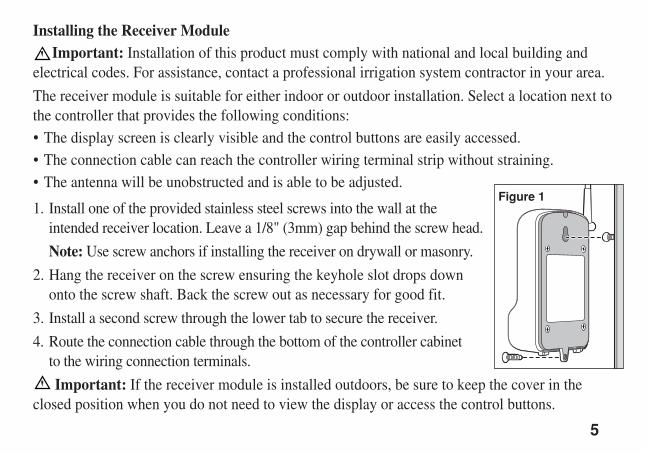
Installing the Receiver ModuleImportant: Installation of this product must comply with national and local building and
electrical codes. For assistance, contact a professional irrigation system contractor in your area.
The receiver module is suitable for either indoor or outdoor installation. Select a location next tothe controller that provides the following conditions:• The display screen is clearly visible and the control buttons are easily accessed.• The connection cable can reach the controller wiring terminal strip without straining.• The antenna will be unobstructed and is able to be adjusted.
1. Install one of the provided stainless steel screws into the wall at theintended receiver location. Leave a 1/8" (3mm) gap behind the screw head.
Note: Use screw anchors if installing the receiver on drywall or masonry.
2. Hang the receiver on the screw ensuring the keyhole slot drops downonto the screw shaft. Back the screw out as necessary for good fit.
3. Install a second screw through the lower tab to secure the receiver.
4. Route the connection cable through the bottom of the controller cabinet to the wiring connection terminals.
Important: If the receiver module is installed outdoors, be sure to keep the cover in theclosed position when you do not need to view the display or access the control buttons.
5
Figure 1
RainSensorAlpha7 3/10/2005 3:31 PM Page 5
6
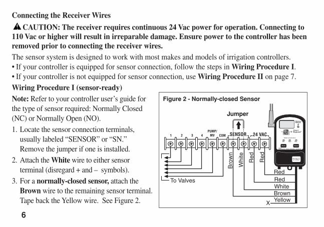
Connecting the Receiver Wires
CAUTION: The receiver requires continuous 24 Vac power for operation. Connecting to110 Vac or higher will result in irreparable damage. Ensure power to the controller has beenremoved prior to connecting the receiver wires.The sensor system is designed to work with most makes and models of irrigation controllers.• If your controller is equipped for sensor connection, follow the steps in Wiring Procedure I. • If your controller is not equipped for sensor connection, use Wiring Procedure II on page 7.Wiring Procedure I (sensor-ready)Note: Refer to your controller user’s guide for the type of sensor required: Normally Closed(NC) or Normally Open (NO).1. Locate the sensor connection terminals,
usually labeled “SENSOR” or “SN.” Remove the jumper if one is installed.
2. Attach the White wire to either sensorterminal (disregard + and – symbols).
3. For a normally-closed sensor, attach theBrown wire to the remaining sensor terminal. Tape back the Yellow wire. See Figure 2.
COMPUMP/
MV 24 VAC21 3 4 SENSOR
Red
RedRedWhiteBrownYellow
Red
Whi
te
Bro
wn
To Valves
X
Jumper
Figure 2 - Normally-closed Sensor
RainSensorAlpha7 3/10/2005 3:31 PM Page 6
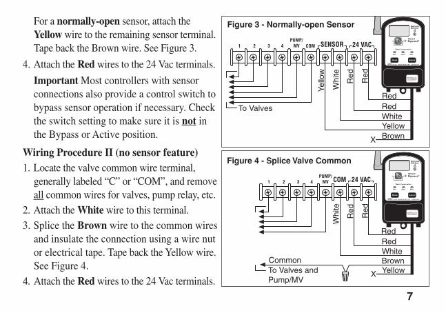
For a normally-open sensor, attach theYellow wire to the remaining sensor terminal.Tape back the Brown wire. See Figure 3.
4. Attach the Red wires to the 24 Vac terminals.
Important Most controllers with sensorconnections also provide a control switch tobypass sensor operation if necessary. Checkthe switch setting to make sure it is not inthe Bypass or Active position.
Wiring Procedure II (no sensor feature)1. Locate the valve common wire terminal,
generally labeled “C” or “COM”, and removeall common wires for valves, pump relay, etc.
2. Attach the White wire to this terminal.3. Splice the Brown wire to the common wires
and insulate the connection using a wire nutor electrical tape. Tape back the Yellow wire.See Figure 4.
4. Attach the Red wires to the 24 Vac terminals.
7
COMPUMP/
MV 24 VAC21 3 4 SENSOR
Red
RedRedWhiteYellow
Red
Whi
te
Yello
w
BrownX
To Valves
PUMP/ MV 24 VACCOM21 3 4
Red
RedRedWhite
Whi
te
Brown
Red
CommonTo Valves and Pump/MV
YellowX
Figure 3 - Normally-open Sensor
Figure 4 - Splice Valve Common
RainSensorAlpha7 3/10/2005 3:31 PM Page 7
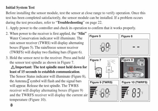
Initial System TestBefore installing the sensor module, test the sensor at close range to verify operation. Once thistest has been completed satisfactorily, the sensor module can be installed. If a problem occursduring the test procedure, refer to “Troubleshooting” on page 22.1. Apply power to the controller and check its operation to confirm that it works properly.
2. When power to the receiver is first applied, the “Min”Water Conservation indicator will illuminate. Therain sensor receiver (TWRS) will display alternatingboxes (Figure 5). The rain/freeze sensor receiver(TWRFS) will display two flashing bars (Figure 6).
3. Hold the sensor next to the receiver. Press and holdthe sensor test spindle as shown in Figure 7.
Important: The test spindle must held down forleast of 15 seconds to establish communication. The Sensor Status indicator will illuminate (Figure 8),the Antenna symbol will flash and the signal barswill appear. Release the test spindle. The TWRSreceiver will display alternating boxes (Figure 9)and the TWRFS receiver will display the current airtemperature (Figure 10).
8
Figure 6
Figure 7
Figure 5
Figure 8
Figure 10 (TWRFS)Figure 9 (TWRS)
RainSensorAlpha7 3/10/2005 3:31 PM Page 8
9
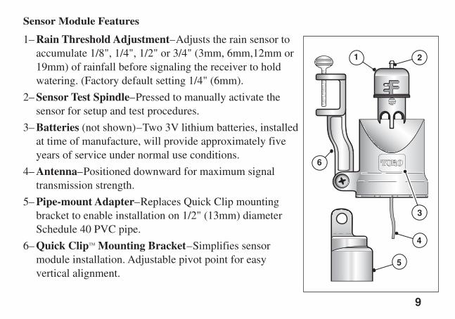
Sensor Module Features
1– Rain Threshold Adjustment–Adjusts the rain sensor toaccumulate 1/8", 1/4", 1/2" or 3/4" (3mm, 6mm,12mm or19mm) of rainfall before signaling the receiver to holdwatering. (Factory default setting 1/4" (6mm).
2– Sensor Test Spindle–Pressed to manually activate thesensor for setup and test procedures.
3– Batteries (not shown)–Two 3V lithium batteries, installedat time of manufacture, will provide approximately fiveyears of service under normal use conditions.
4– Antenna–Positioned downward for maximum signaltransmission strength.
5– Pipe-mount Adapter–Replaces Quick Clip mountingbracket to enable installation on 1/2" (13mm) diameterSchedule 40 PVC pipe.
6– Quick ClipTM Mounting Bracket–Simplifies sensormodule installation. Adjustable pivot point for easyvertical alignment.
1 2
3
4
5
6
RainSensorAlpha7 3/10/2005 3:31 PM Page 9
10
Installing the Sensor ModuleChoosing the right installation site for the sensor module is the key to getting the maximum benefitfrom your sensor system. Select a sensor installation site that provides the following conditions: • Unobstructed exposure to rainfall–away from overhangs, tree branches, etc.• Protected from irrigation spray, rainwater accumulation and the possibility of submersion.• Exposure to sunlight and shade conditions similar to the landscape being watered.• Strong communication signal from the sensor to the receiver.Note: If installing a Rain/Freeze sensor specifically for freeze detection, refer to the additionalsite selection considerations provided on page 13.Before installing the sensor module, test the system once more to confirm operation by using thefollowing test procedure:1. Activate a watering zone that is visible from the intended installation site.
Note: The manual operations mode of some controllers will bypass the sensor circuit. If yourcontroller operates like this, set an automatic start time to have the sprinklers run now.
2. With the sprinklers on, press and hold the sensor spindle until the sprinklers shut off, thenrelease the spindle. If the test is successful, the sensor is ready to install. If the sprinklers do notshut off, try moving the sensor a few feet in either direction and test again. Moving the receiverantenna slightly may also improve the signal strength.
Refer to “Troubleshooting” on page 22 for additional information.
RainSensorAlpha7 3/10/2005 3:31 PM Page 10
11
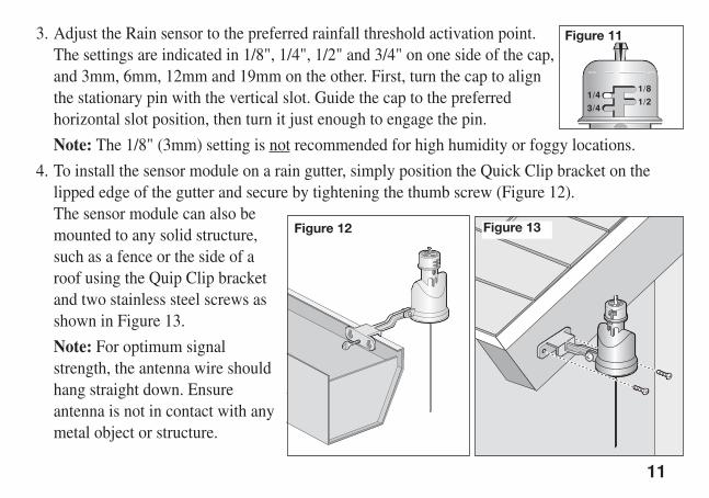
3. Adjust the Rain sensor to the preferred rainfall threshold activation point. The settings are indicated in 1/8", 1/4", 1/2" and 3/4" on one side of the cap,and 3mm, 6mm, 12mm and 19mm on the other. First, turn the cap to alignthe stationary pin with the vertical slot. Guide the cap to the preferredhorizontal slot position, then turn it just enough to engage the pin.
Note: The 1/8" (3mm) setting is not recommended for high humidity or foggy locations.
4. To install the sensor module on a rain gutter, simply position the Quick Clip bracket on thelipped edge of the gutter and secure by tightening the thumb screw (Figure 12). The sensor module can also bemounted to any solid structure,such as a fence or the side of aroof using the Quip Clip bracketand two stainless steel screws asshown in Figure 13.
Note: For optimum signalstrength, the antenna wire shouldhang straight down. Ensureantenna is not in contact with anymetal object or structure.
3/4
1/41/2
1/8
Figure 11
Figure 12 Figure 13
RainSensorAlpha7 3/10/2005 3:31 PM Page 11
12
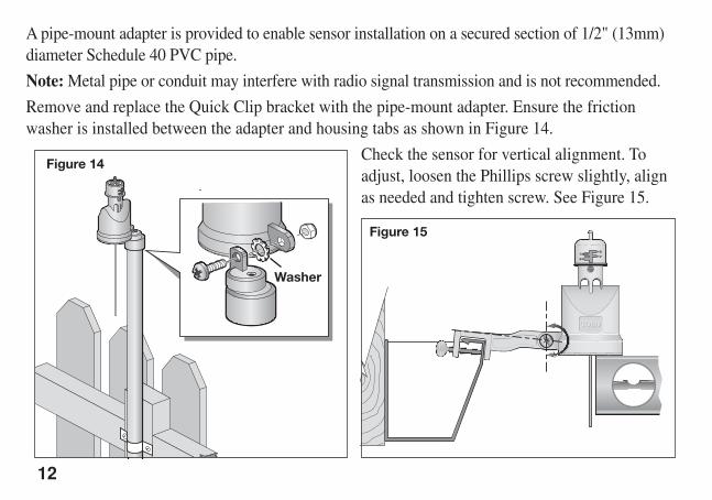
A pipe-mount adapter is provided to enable sensor installation on a secured section of 1/2" (13mm)diameter Schedule 40 PVC pipe.
Note: Metal pipe or conduit may interfere with radio signal transmission and is not recommended.
Remove and replace the Quick Clip bracket with the pipe-mount adapter. Ensure the frictionwasher is installed between the adapter and housing tabs as shown in Figure 14.
Check the sensor for vertical alignment. Toadjust, loosen the Phillips screw slightly, alignas needed and tighten screw. See Figure 15.
Figure 14
Figure 15
Washer
RainSensorAlpha7 3/10/2005 3:31 PM Page 12
Freeze Sensor Site SelectionIn addition to the rain sensor site conditions listed on page 10, the following conditions arenecessary to ensure optimum freeze sensor operation. For best results, the sensor should be:• Located in the coldest portion of the landscape.• Away from direct exposure to morning sunlight.• Away from any heat producing or storing device, equipment or appliance such as a pool/spa,
heater, water heater, chimney or hot air vent pipe.
Important: Visual checks and prudent manual watering suspension must be used inconjunction with any freeze sensor. A freeze sensor should only be relied upon as an aid toconscientious watering practices, including frequent visual checks. Air temperatures may beabove freezing while the ground and vegetation temperatures remain below freezing. Due tosensor location and sunlight exposure, actual air temperature may be lower than measured by thesensor. Operation of the sprinkler system during these conditions may cause icing. Freeze sensorresponse time may not coincide with extremely rapid temperature drop, enabling automaticirrigation to occur.
13
CAUTION: The rain/freeze sensor module should be regularly inspected for damageand manually tested to ensure proper operation.The Toro Wireless Rain/Freeze sensor system is NOT intended for farm/crop freezeprotection and must not be used for this purpose.
RainSensorAlpha7 3/10/2005 3:31 PM Page 13
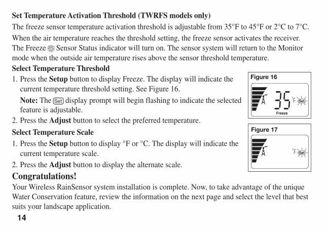
Set Temperature Activation Threshold (TWRFS models only)The freeze sensor temperature activation threshold is adjustable from 35°F to 45°F or 2°C to 7°C.When the air temperature reaches the threshold setting, the freeze sensor activates the receiver.The Freeze Sensor Status indicator will turn on. The sensor system will return to the Monitormode when the outside air temperature rises above the sensor threshold temperature.Select Temperature Threshold1. Press the Setup button to display Freeze. The display will indicate the
current temperature threshold setting. See Figure 16.
Note: The display prompt will begin flashing to indicate the selectedfeature is adjustable.
2. Press the Adjust button to select the preferred temperature.
Select Temperature Scale1. Press the Setup button to display °F or °C. The display will indicate the
current temperature scale. 2. Press the Adjust button to display the alternate scale.
Congratulations!Your Wireless RainSensor system installation is complete. Now, to take advantage of the uniqueWater Conservation feature, review the information on the next page and select the level that bestsuits your landscape application.
14
Figure 16
Figure 17
RainSensorAlpha7 3/10/2005 3:31 PM Page 14
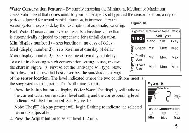
Water Conservation Feature – By simply choosing the Minimum, Medium or Maximumconservation level that corresponds to your landscape’s soil type and the sensor location, a dry-outperiod, adjusted for actual rainfall duration, is inserted after the sensor system resets to delay the resumption of automatic watering.Each Water Conservation level represents a baseline value that is automatically adjusted to compensate for rainfall duration.Min (display number 1) – sets baseline at no days of delay.Med (display number 2) – sets baseline at one day of delay.Max (display number 3) – sets baseline at two days of delay.To assist in choosing which conservation setting to use, review the chart in Figure 18. First select the landscape soil type. Now, drop down to the row that best describes the sun/shade coverage of the sensor location. The level indicated where the two conditions meet isthe suggested starting point. That’s all there is to it!1. Press the Setup button to display Water Save. The display will indicate
the current water conservation level setting and the corresponding levelindicator will be illuminated. See Figure 19.Note: The display prompt will begin flashing to indicate the selectedfeature is adjustable.
2. Press the Adjust button to select level 1, 2 or 3.
15
Figure 19
Figure 18
RainSensorAlpha7 3/10/2005 3:31 PM Page 15
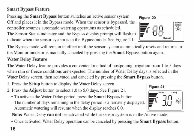
Smart Bypass Feature
Pressing the Smart Bypass button switches an active sensor systemOff and places it in the Bypass mode. When the sensor is bypassed, thecontroller resumes automatic watering operations as scheduled. The Sensor Status indicator and the Bypass display prompt will flash toindicate when the sensor system is in the Bypass mode. See Figure 20.
The Bypass mode will remain in effect until the sensor system automatically resets and returns tothe Monitor mode or is manually canceled by pressing the Smart Bypass button again. Water Delay FeatureThe Water Delay feature provides a convenient method of postponing irrigation from 1 to 5 dayswhen rain or freeze conditions are expected. The number of Water Delay days is selected in theWater Delay screen, then activated and canceled by pressing the Smart Bypass button.
1. Press the Setup button to display the Water Delay screen. 2. Press the Adjust button to select 1.0 to 5.0 days. See Figure 21.
• To activate the Water Delay period, press the Smart Bypass button.The number of days remaining in the delay period is alternately displayed.Automatic watering will resume when the display reaches 0.0.
Note: Water Delay can not be activated while the sensor system is in the Active mode.
• Once activated, Water Delay operation can be canceled by pressing the Smart Bypass button.
16
Figure 21
Figure 20
RainSensorAlpha7 3/10/2005 3:31 PM Page 16
17
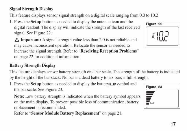
Signal Strength DisplayThis feature displays sensor signal strength on a digital scale ranging from 0.0 to 10.2 1. Press the Setup button as needed to display the antenna icon and the
digital readout. The display will indicate the strength of the last receivedsignal. See Figure 22.
Important: A signal strength value less than 2.0 is not reliable andmay cause inconsistent operation. Relocate the sensor as needed toincrease the signal strength. Refer to “Resolving Reception Problems” on page 22 for additional information.
Battery Strength DisplayThis feature displays sensor battery strength on a bar scale. The strength of the battery is indicatedby the height of the bar stack: No bar = a dead battery to six bars = full strength. 1. Press the Setup button as needed to display the battery symbol and
the bar scale. See Figure 23.
Note: Low battery strength is indicated when the battery symbol appearson the main display. To prevent possible loss of communication, batteryreplacement is recommended. Refer to “Sensor Module Battery Replacement” on page 21.
Figure 22
Figure 23
RainSensorAlpha7 3/10/2005 3:31 PM Page 17
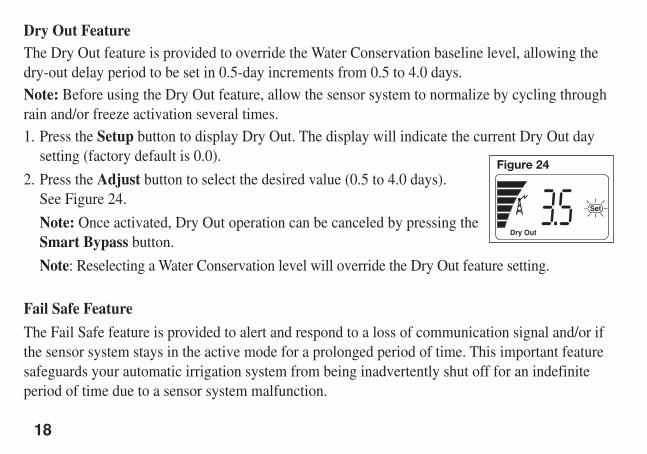
Dry Out FeatureThe Dry Out feature is provided to override the Water Conservation baseline level, allowing thedry-out delay period to be set in 0.5-day increments from 0.5 to 4.0 days.Note: Before using the Dry Out feature, allow the sensor system to normalize by cycling throughrain and/or freeze activation several times.1. Press the Setup button to display Dry Out. The display will indicate the current Dry Out day
setting (factory default is 0.0).
2. Press the Adjust button to select the desired value (0.5 to 4.0 days).See Figure 24.
Note: Once activated, Dry Out operation can be canceled by pressing theSmart Bypass button.
Note: Reselecting a Water Conservation level will override the Dry Out feature setting.
Fail Safe Feature
The Fail Safe feature is provided to alert and respond to a loss of communication signal and/or ifthe sensor system stays in the active mode for a prolonged period of time. This important featuresafeguards your automatic irrigation system from being inadvertently shut off for an indefiniteperiod of time due to a sensor system malfunction.
18
Figure 24
RainSensorAlpha7 3/10/2005 3:31 PM Page 18
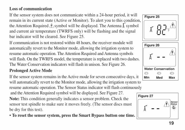
Loss of communicationIf the sensor system does not communicate within a 24-hour period, it willremain in its current state (Active or Monitor). To alert you to this condition,the Attention Required symbol will be displayed. The Antenna symboland current air temperature (TWRFS only) will be flashing and the signalbar indicator will be cleared. See Figure 25.If communication is not restored within 48 hours, the receiver module willautomatically revert to the Monitor mode, allowing the irrigation system toresume automatic operation. The Attention Required and Antenna symbols will flash. On the TWRFS model, the temperature is replaced with two dashes. The Water Conservation indicators will flash in unison. See Figure 26.Prolonged Active Mode If the sensor system remains in the Active mode for seven consecutive days, itwill automatically revert to the Monitor mode, allowing the irrigation system toresume automatic operation. The Sensor Status indicator will flash continuouslyand the Attention Required symbol will be displayed. See Figure 27.Note: This condition generally indicates a sensor problem. Check thesensor test spindle to make sure it moves freely. (The sensor discs mustbe dry for this test).• To reset the sensor system, press the Smart Bypass button one time.
19
Figure 26
Figure 27
Figure 25
RainSensorAlpha7 3/10/2005 3:31 PM Page 19
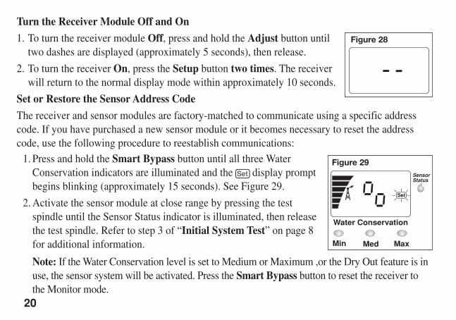
Turn the Receiver Module Off and On
1. To turn the receiver module Off, press and hold the Adjust button untiltwo dashes are displayed (approximately 5 seconds), then release.
2. To turn the receiver On, press the Setup button two times. The receiverwill return to the normal display mode within approximately 10 seconds.
Set or Restore the Sensor Address Code
The receiver and sensor modules are factory-matched to communicate using a specific addresscode. If you have purchased a new sensor module or it becomes necessary to reset the addresscode, use the following procedure to reestablish communications:
1. Press and hold the Smart Bypass button until all three WaterConservation indicators are illuminated and the display promptbegins blinking (approximately 15 seconds). See Figure 29.
2. Activate the sensor module at close range by pressing the testspindle until the Sensor Status indicator is illuminated, then releasethe test spindle. Refer to step 3 of “Initial System Test” on page 8for additional information.
Note: If the Water Conservation level is set to Medium or Maximum ,or the Dry Out feature is inuse, the sensor system will be activated. Press the Smart Bypass button to reset the receiver tothe Monitor mode.
20
Figure 28
Figure 29
RainSensorAlpha7 3/10/2005 3:31 PM Page 20
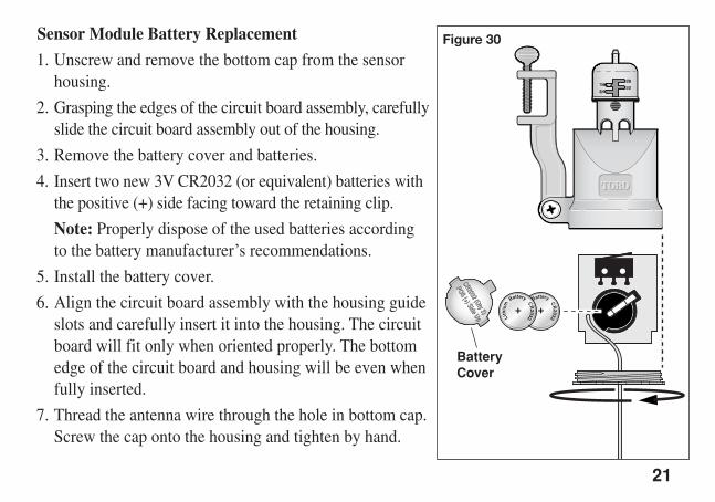
Sensor Module Battery Replacement
1. Unscrew and remove the bottom cap from the sensorhousing.
2. Grasping the edges of the circuit board assembly, carefullyslide the circuit board assembly out of the housing.
3. Remove the battery cover and batteries.
4. Insert two new 3V CR2032 (or equivalent) batteries withthe positive (+) side facing toward the retaining clip.
Note: Properly dispose of the used batteries according to the battery manufacturer’s recommendations.
5. Install the battery cover.
6. Align the circuit board assembly with the housing guideslots and carefully insert it into the housing. The circuitboard will fit only when oriented properly. The bottomedge of the circuit board and housing will be even whenfully inserted.
7. Thread the antenna wire through the hole in bottom cap.Screw the cap onto the housing and tighten by hand.
21
Figure 30
BatteryCover
RainSensorAlpha7 3/10/2005 3:31 PM Page 21
TroubleshootingIf you encounter problems at any point in the installation process, or the components do not seemto function properly, try the Troubleshooting procedures first. If the problem is not listed or theremedy does not resolve the problem, call the Toro Irrigation help line at 1-800-664-4740.
Solving Reception Problems
The Wireless RainSensor has an operating range of 500' (152.4m) LOS (Line-of-Site).
Note: Line-of-Site is a radio signal transmission measurement standard equivalent to an openfield site with no obstructions.
However, in most cases, there are buildings or other objects between the sensor and receivermodules that can reduce signal strength. Most residential and light commercial buildings do notreduce the signal enough to pose problems under normal conditions. However, there are somestructures with very thick, dense walls, or that involve large amounts of radio frequencyinterference due to electronic equipment that can reduce the sensor signal range.
To improve signal strength:• Move the antenna away from any large metal object. • Avoid indoor receiver locations where cellular or cordless phones have trouble with reception. • Mount the sensor and receiver modules as close together as possible.• Move the sensor module to one side if is installed directly over the receiver module.
22
RainSensorAlpha7 3/10/2005 3:31 PM Page 22
The receiver display is blank.• Check the 24 Vac power connections. The red power wires from the receiver must be connected
to the controller’s 24 Vac power source. Make sure the power wires are not connected to thestation or pump/master valve terminals. These terminals only provide 24 Vac power when thecontroller is operating the sprinkler zones.
The sensor module does not activate the receiver at close range.• The receiver module may not recognize the sensor module address code. See “Set or Restore
Sensor Address Code” on page 20.
• Remove and replace the sensor module batteries.
The sensor system works, but the controller does not respond to the sensor.
• Check the Yellow or Brown wire connection. The Brown wire must be used for NormallyClosed (NC) controller operation and Yellow wire for Normally Open (NO) operation.
• The Brown wire must be used when splicing into the valve common wire.• Make sure the controller’s “Sensor Bypass” switch is not in the Bypass or Active position.
23
RainSensorAlpha7 3/10/2005 3:31 PM Page 23
24
Specifications
Models: TWRS (Wireless RainSensor) and TWRFS (Wireless Rain/Freeze Sensor)Wireless Communication Range: 500' (152.4m) LOS (line-of site)Sensor Type: Industry-standard hygroscopic disc stack with adjustable rainfall sensitivitySensor Module Batteries: (2) 3V cells - CR2032 (or equivalent)Average Battery Life: 5 yearsOperating Temperature Range: -20°F to 120°F (-29°C to 49°C)Receiver Power: 22–28 Vac/Vdc, 100mA (from controller w/Class 2, UL-approved transformer)Relay Contacts Output: Normally Open (NO) and Normally Closed (NC) 3A at 24 Vac
RainSensorAlpha7 3/10/2005 3:31 PM Page 24

The Toro Promise – Five-year Limited WarrantyThe Toro Company and its affiliate, Toro Warranty Company, pursuant to an agreement between them, jointly warrants, to
the owner, each new piece of equipment (featured in the current catalog at date of installation) against defects in material andworkmanship for for a period described below, provided they are used for irrigation purposes under manufacturer'srecommended specifications. Product failures due to acts of God (i.e., lightning, flooding, etc.) are not covered by this warranty.
Neither Toro nor Toro Warranty Company is liable for failure of products not manufactured by them even though suchproducts may be sold or used in conjunction with Toro products.
During such warranty period, we will repair or replace, at our option, any part found to be defective. Your remedy is limitedsolely to the replacement or repair of defective parts.
Return the defective part to your local Toro distributor, who may be listed in your telephone directory Yellow Pages under"Irrigation Supplies" or "Sprinkler Systems," or contact The Toro Warranty Company P.O. Box 489, Riverside, California,92502. Phone (800) 664-4740 for the location of your nearest Toro distributor or outside the U.S., call (951) 688-9221.
This warranty does not apply where equipment is used, or installation is performed in any manner contrary to Toro’sspecifications and instructions, nor where equipment is altered or modified.
Neither Toro nor Toro Warranty Company is liable for indirect, incidental or consequential damages in connection with theuse of equipment, including but not limited to: vegetation loss, the cost of substitute equipment or services required duringperiods of malfunction or resulting non-use, property damage or personal injury resulting from installer’s actions, whethernegligent or otherwise.
Some states do not allow the exclusion or limitation of incidental or consequential damages, so the above limitation orexclusion may not apply to you.
All implied warranties, including those of merchantability and fitness for use, are limited to the duration of this expresswarranty.
Some states do not allow limitations of how long an implied warranty lasts, so the above limitation may not apply to you.This warranty gives you specific legal rights and you may have other rights which vary from state to state.The Toro Wireless RainSensor series is covered by this warranty for a period of five years from the date of installation.
25
Electromagnetic CompatibilityDomestic: This device complies with FCC rules Part 15. Operation is subject to the following two conditions: (1)This device may not cause harmful interference and (2) this device must accept any interference that may bereceived, including interference that may cause undesirable operation.This equipment generates and uses radio frequency energy and if not installed and used properly, that is, in strictaccordance with the manufacturer's instructions, may cause interference to radio and television reception. It hasbeen type tested and found to comply with the limits for a FCC Class B computing device in accordance with thespecifications in Subpart J of Part 15 of FCC Rules, which are designed to provide reasonable protection againstsuch interference in a residential installation. However, there is no guarantee that interference will not occur in aparticular installation. If this equipment does cause interference to radio or television reception, which can bedetermined by turning the equipment off and on, the user is encouraged to try to correct the interference by one ormore of the following measures:Reorient the receiving antenna, relocate the remote control receiver with respect to the radio/TV antenna or plugthe irrigation controller into a different outlet so that the irrigation controller and radio/TV are on different branchcircuits.If necessary, the user should consult the dealer or an experienced radio/television technician for additionalsuggestions. The user may find the following booklet prepared by the Federal Communications Commission helpful:"How to Identify and Resolve Radio-TV Interference Problems". This booklet is available from the U.S.Government Printing Office, Washington, DC 20402. Stock No. 004-000-00345-4.
Important: Changes or modifications to this unit, not expressly approved by the party responsible forcompliance, could void the authority to operate the equipment.
FCC ID: OF7TWRSIC: 3575A-TWRS
26© 2005 The Toro Company, Irrigation Division Form Number 373-0332 Rev. A
RainSensorAlpha7 3/10/2005 3:31 PM Page 26