rail accident report - assets.publishing.service.gov.uk · the overspeeding. neither virgin trains...
TRANSCRIPT

Report 14/2016August 2016
Rail Accident Report
Overspeed at Fletton Junction, Peterborough 11 September 2015

This investigation was carried out in accordance with:
l the Railway Safety Directive 2004/49/EC;l the Railways and Transport Safety Act 2003; and l the Railways (Accident Investigation and Reporting) Regulations 2005.
© Crown copyright 2016 You may re-use this document/publication (not including departmental or agency logos) free of charge in any format or medium. You must re-use it accurately and not in a misleading context. The material must be acknowledged as Crown copyright and you must give the title of the source publication. Where we have identified any third party copyright material you will need to obtain permission from the copyright holders concerned. This document/publication is also available at www.raib.gov.uk.
Any enquiries about this publication should be sent to:
RAIB Email: [email protected] Wharf Telephone: 01332 253300Stores Road Fax: 01332 253301 Derby UK Website: www.gov.uk/raibDE21 4BA
This report is published by the Rail Accident Investigation Branch, Department for Transport.
Report 14/2016Fletton Junction
August 2016
Preface
The purpose of a Rail Accident Investigation Branch (RAIB) investigation is to improve railway safety by preventing future railway accidents or by mitigating their consequences. It is not the purpose of such an investigation to establish blame or liability. Accordingly, it is inappropriate that RAIB reports should be used to assign fault or blame, or determine liability, since neither the investigation nor the reporting process has been undertaken for that purpose.
The RAIB’s findings are based on its own evaluation of the evidence that was available at the time of the investigation and are intended to explain what happened, and why, in a fair and unbiased manner.
Where the RAIB has described a factor as being linked to cause and the term is unqualified, this means that the RAIB has satisfied itself that the evidence supports both the presence of the factor and its direct relevance to the causation of the accident. However, where the RAIB is less confident about the existence of a factor, or its role in the causation of the accident, the RAIB will qualify its findings by use of the words ‘probable’ or ‘possible’, as appropriate. Where there is more than one potential explanation the RAIB may describe one factor as being ‘more’ or ‘less’ likely than the other.
In some cases factors are described as ‘underlying’. Such factors are also relevant to the causation of the accident but are associated with the underlying management arrangements or organisational issues (such as working culture). Where necessary, the words ‘probable’ or ‘possible’ can also be used to qualify ‘underlying factor’.
Use of the word ‘probable’ means that, although it is considered highly likely that the factor applied, some small element of uncertainty remains. Use of the word ‘possible’ means that, although there is some evidence that supports this factor, there remains a more significant degree of uncertainty.
An ‘observation’ is a safety issue discovered as part of the investigation that is not considered to be causal or underlying to the event being investigated, but does deserve scrutiny because of a perceived potential for safety learning.
The above terms are intended to assist readers’ interpretation of the report, and to provide suitable explanations where uncertainty remains. The report should therefore be interpreted as the view of the RAIB, expressed with the sole purpose of improving railway safety.
The RAIB’s investigation (including its scope, methods, conclusions and recommendations) is independent of any inquest or fatal accident inquiry, and all other investigations, including those carried out by the safety authority, police or railway industry.
Pref
ace

Report 14/2016Fletton Junction
4 August 2016
This page is intentionally left blank
Report 14/2016Fletton Junction
August 2016

Report 14/2016Fletton Junction
5 August 2016
Overspeed at Fletton Junction, Peterborough, 11 September 2015
Contents
Preface 3Summary 7Introduction 8
Key definitions 8The incident 9
Summary of the incident 9Context 9
The sequence of events 15Key facts and analysis 18
Identification of the immediate cause 18Identification of causal factors 18Identification of underlying factors 28Observations 33Previous occurrences of a similar character 34
Summary of conclusions 36Immediate cause 36Causal factors 36Underlying factors 36Observations 36
Actions reported as already taken or in progress relevant to this report 38Other reported actions 38
Recommendations and learning points 39Recommendations 39Learning points 41
Appendices 42Appendix A - Glossary of abbreviations and acronyms 42Appendix B - Glossary of terms 43Appendix C - Investigation details 46Appendix D - TPWS set speed of 76 mph (122 km/h) 47

Report 14/2016Fletton Junction
6 August 2016
This page is intentionally left blank

Report 14/2016Fletton Junction
7 August 2016
Summary
At around 17:11 hrs on Friday 11 September 2015, the 14:25 hrs Virgin Trains East Coast passenger train service from Newcastle to London King’s Cross passed through Fletton Junction, near Peterborough at 51 mph (82 km/h) around twice the permitted speed of 25 mph (40 km/h). This caused the carriages to lurch sideways resulting in minor injuries to three members of staff and one passenger. It is likely that the train driver had forgotten about the presence of the speed restriction because he was distracted and fatigued due to issues related to his family. Lineside signs and in-cab warnings may have contributed to him not responding appropriately as he approached the speed restriction and engineering controls did not prevent the overspeeding. Neither Virgin Trains East Coast, nor the driver, had realised that family-related distraction and fatigue were likely to be affecting the safety of his driving. Virgin Trains East Coast’s route risk assessment had not recognised the overspeeding risks particular to Fletton Junction and Network Rail had not identified that a speed limit sign at the start of the speed restriction was smaller than required by its standards. The incident could have had more serious consequences if the train had derailed or overturned. The risk of this was present because the track layout was designed for a maximum speed of 27 mph (43 km/h). The RAIB has made five recommendations. Two addressed to Virgin Trains East Coast relate to enhancing the management of safety critical staff who are experiencing problems related to their home life, and considering such issues during the investigation of unsafe events. A recommendation addressed to Virgin Trains East Coast and an associated recommendation addressed to Network Rail relate to assessing and mitigating risks at speed restrictions. A further recommendation to Network Rail relates to replacement of operational signage when this is non-compliant with relevant standards. The RAIB report also includes learning points relating to managing personal problems that could affect the safety performance of drivers. A further learning point, arising because of a delay in reporting the incident, stresses the importance of drivers promptly reporting incidents which could have caused track damage. A final learning point encourages a full understanding of the effectiveness of safety mitigation provided by infrastructure and signalling equipment.
Sum
mar
y

Report 14/2016Fletton Junction
8 August 2016
Introduction
Key definitions1 Metric units are used in this report, except when it is normal railway practice to
give speeds and locations in imperial units. Where appropriate the equivalent metric value is also given.
2 Distances from Peterborough station are measured from the approximate position of the front of the incident train when it was standing at the station.
3 The report contains abbreviations and technical terms (shown in italics the first time they appear in the report). These are explained in appendices A and B. Sources of evidence used in the investigation are listed in appendix C.
Introduction

Report 14/2016Fletton Junction
9 August 2016
© Crown Copyright. All rights reserved. Department for Transport 100039241. RAIB 2016
Location of incident
The incident
Summary of the incident4 At around 17:11 hrs on Friday 11 September 2015, the 14:25 hrs Virgin Trains
East Coast passenger train service from Newcastle to London King’s Cross, reporting number 1Y38, passed through Fletton Junction, near Peterborough (figure 1) at around twice the permitted speed of 25 mph (40 km/h). This caused the carriages to lurch sideways and resulted in minor injuries to three members of staff and one passenger.
5 The train’s driver did not report the overspeeding incident, but the injuries to the on-train staff and passenger were reported to Virgin Trains East Coast control by staff on the train.
Figure 1: Extract from Ordnance Survey map showing location of the incident
ContextLocation6 Fletton Junction is on the East Coast main line around 1.25 miles (2 km) south
of Peterborough station and 75 miles and 2 chains1 from King’s Cross station. At this junction, the up slow and up fast lines merge to become the up main line (figure 2).
7 These lines carry trains travelling south from Peterborough. The up slow line passes through platform 1 at Peterborough station and the up fast passes through platform 3. Southbound trains departing from platform 1 can be routed onto the up fast line at a crossover immediately south of the station, or continue along the up slow line to Fletton Junction.
1 One chain is 22 yards or approximately 20 metres.
The
acci
dent

Report 14/2016Fletton Junction
10 August 2016
TPWS OSS loops (not shown on up fast)
Maximum speeds (mph) through station
0 m
15m
70 m
210 m
400 m
1020 m
1100 m
1130 m
1145 m
1200 m
1600 m
P438P436
P428P430
P430BR
P440
1735 m
Toe of points 1730 m
1380 m
TPWS TSS loopsAWS magnetsBanner
repeating signal
Speed limit sign
Advanced warning indicator
Three aspect signal
Four aspect signal
Path of train 1Y38Up slow line
Up fast line
Up main
line
To London King’s Cross
Fletton Junction
Peterborough station
● Not to scale● Only shows selected infrastructure ● Distances measured from approximate position of front of train 1Y38 when standing at platform 1
P428BR
125 30
25
25
Front of train 1Y38 when standing in platform 1
Speed limit sign (start 70 mph maximum speed)
AWS for warning indicator
Warning indicator (lineside sign)
TPWS OSS for 25 mph restriction
TPWS OSS for signal P428
Banner repeating signal for signal P428
Bridge over railway
AWS for signal P428
Signal P428
Signal P436
Speed limit sign at start of 25 mph restriction
70
115
115
25
70
12 Platform numbers3
50
105
Figure 2: Infrastructure between Peterborough station and Fletton Junction (simplified)
The accident

Report 14/2016Fletton Junction
11 August 2016
8 The maximum permitted speed along the up slow line through Peterborough station is 50 mph (80 km/h)2 and this increases to 70 mph (113 km/h) just south of Peterborough station3 before reducing to 25 mph (40 km/h) around 130 metres before Fletton Junction (the track layout approaching the junction from the up slow line to the up fast line was designed for a maximum speed of 27 mph (43 km/h))4. The maximum permitted speed on the up main line beyond Fletton Junction is 115 mph (185 km/h). The maximum permitted speed on the up fast line through Peterborough station is 125 mph (201 km/h) which reduces to 105 mph (169 km/h) just south of the station5 before increasing to 115 mph (185 km/h) shortly before Fletton Junction.
Organisations involved9 Virgin Trains East Coast (VTEC) operated train 1Y38 and employed the driver
and on-board staff including the guard and catering crew leader. 10 Network Rail owns and manages the infrastructure. 11 Network Rail and VTEC also employ staff working in the joint control centre at
York. These staff include VTEC’s duty control manager. 12 Both organisations freely co-operated with the investigation. Train involved13 Train 1Y38 consisted of an Intercity 225 electric train set. These trains comprise
a driving van trailer, nine mark IV passenger coaches, and a class 91 locomotive giving a total length of around 249 metres.
14 Train 1Y38 was being driven from the driving van trailer (number 82223) at the front of the train. Equipment fitted to this vehicle included:a. An automatic warning system (AWS) receiver which responds to magnets
fixed to the track between the rails. A single permanent magnet is provided at locations where the AWS is always required to provide a warning. At other locations, an electro-magnet is added and energised when a clear indication is required. If a warning is given, a horn sounds in the driving cab, and if the driver does not acknowledge this warning within about 2 seconds6, the train’s brakes will automatically apply to stop the train. If a clear indication is given, an electronic bell sounds in the driver’s cab and the driver is not required to take any action. An AWS visual indicator in the driving cab, sometimes known as a ‘sunflower’, displays alternate black and yellow segments as a visual reminder to the driver if a warning was acknowledged at the last AWS location. In other circumstances it shows an all-black indication and this is the normal indication after passing an AWS location associated with a signal displaying a green aspect (figure 3).
2 Some trains are limited to speeds lower than the maximum values permitted on a section of track. 3 The up slow 70 mph limit commences about 125 metres from Peterborough station.4 The designers of the layout at Fletton Junction rounded speeds down to the nearest 5 mph in accordance with normal railway practice. 5 The up fast 105 mph limit starts about 116 metres after the start of the up slow 70 mph limit.6 AWS response times depend on the type of train, as described in Railway Group Standard GE/RT8075, AWS and TPWS Interface Requirements.
The
acci
dent

Report 14/2016Fletton Junction
12 August 2016
AWS indicator showing warning indication (black and yellow segments)
AWS indicator showing clear indication (black segments)
CCTV image from train 1Y38
Sign when maximum permitted speed changes to 70 mph approximately 70 metres after train 1Y38 leaves Peterborough station
Up slow
Up fast
b. A train protection and warning system (TPWS) which triggers an emergency brake application when encountering loops mounted on the track which are primed (ie transmitting radio signals) and:i. the train is exceeding a defined speed (the set speed) as it passes over a
pair of loops configured as an overspeed sensor (OSS); orii. the train has passed a stop signal and passes over a pair of loops
configured as a train stop system (TSS).c. An automatic speed limiter which controls the train speed to a value set
manually by the driver.
Figure 3: AWS visual indicator Rail equipment/systems involved15 Speed limit signs (referred to as permissible speed indicators in the railway rule
book) are provided on both the up slow and up fast lines at the locations where a new maximum permitted speed applies (figure 4). A 115 mph sign is provided on the up main line, shortly after Fletton Junction, to advise drivers joining from the up slow line that they are now subject to the limit which already applies to trains travelling from the up fast line.
Figure 4: Speed limit sign at location where speed changes (courtesy VTEC)
The accident

Report 14/2016Fletton Junction
13 August 2016
CCTV image from train 1Y38
Banner repeating signal for P428showing that P428 is displaying a proceed aspect
Banner repeating signal for P430showing that P430 is displaying a stop aspect
Up slow
Up fast
16 There are two three-aspect colour light signals positioned along the up slow line between Peterborough station platform 1 and Fletton Junction. The first, signal P436, is located around 15 metres south of Peterborough station and the second, P428, is located around 350 metres before Fletton Junction (figure 2). Each of these signals is capable of showing either a red, yellow or green aspect. A red aspect means the train must stop; a yellow aspect means that the train driver must be prepared to stop at the next signal (usually because it is displaying a red aspect), and a green aspect means the train can proceed normally as the next signal is displaying a proceed (yellow or green) aspect. AWS equipment is provided on the approach to these signals. This provides a warning if the signal is displaying a red or yellow aspect and a clear indication if the signal is displaying a green aspect.
17 Both of these signals are preceded by a TPWS OSS, and both are fitted with a TPWS TSS. These TPWS loops are primed only if the signal is displaying a red aspect.
18 Signal P428 is also preceded by a banner repeating signal (figure 5) which displays a horizontal black bar if signal P428 is showing a red aspect, and a diagonal bar if it is showing a proceed aspect. The banner repeating signal is provided because a bridge over the railway means that drivers do not have a clear view of the signal until they are relatively close to it. Banner repeating signals mean that train drivers do not have to drive as slowly towards a signal they cannot see if it is showing a proceed aspect.
Figure 5: Banner repeating signals (courtesy VTEC)
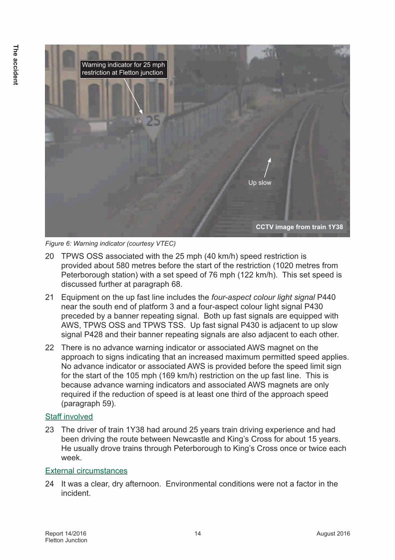
19 A warning indicator for the 25 mph (40 km/h) speed restriction at Fletton Junction is provided by a triangular sign (figure 6) 1200 metres from the start of the restriction (400 metres from Peterborough station). This has an associated AWS permanent magnet which always gives a warning signal and is located 1390 metres from the start of the speed restriction (210 metres from Peterborough station). Paragraph 59 explains why this particular 25 mph (40 km/h) speed restriction requires a warning indicator.
The
acci
dent
Report 14/2016Fletton Junction
14 August 2016
CCTV image from train 1Y38
Warning indicator for 25 mph restriction at Fletton junction
Up slow
Figure 6: Warning indicator (courtesy VTEC)
20 TPWS OSS associated with the 25 mph (40 km/h) speed restriction is provided about 580 metres before the start of the restriction (1020 metres from Peterborough station) with a set speed of 76 mph (122 km/h). This set speed is discussed further at paragraph 68.
21 Equipment on the up fast line includes the four-aspect colour light signal P440 near the south end of platform 3 and a four-aspect colour light signal P430 preceded by a banner repeating signal. Both up fast signals are equipped with AWS, TPWS OSS and TPWS TSS. Up fast signal P430 is adjacent to up slow signal P428 and their banner repeating signals are also adjacent to each other.
22 There is no advance warning indicator or associated AWS magnet on the approach to signs indicating that an increased maximum permitted speed applies. No advance indicator or associated AWS is provided before the speed limit sign for the start of the 105 mph (169 km/h) restriction on the up fast line. This is because advance warning indicators and associated AWS magnets are only required if the reduction of speed is at least one third of the approach speed (paragraph 59).
Staff involved23 The driver of train 1Y38 had around 25 years train driving experience and had
been driving the route between Newcastle and King’s Cross for about 15 years. He usually drove trains through Peterborough to King’s Cross once or twice each week.
External circumstances24 It was a clear, dry afternoon. Environmental conditions were not a factor in the
incident.
The accident

Report 14/2016Fletton Junction
15 August 2016
The sequence of events
Events preceding the incident 7
25 The driver of train 1Y38 booked on duty at Newcastle at around 13:58 hours and his first driving duty was to take train 1Y38 from Newcastle to King’s Cross. He departed from Newcastle on time at 14:25 hrs but was delayed by about 18 minutes approaching Darlington because another train had failed due to a technical fault.
26 At about 17:07 hrs, train 1Y38 arrived in platform 1 at Peterborough station. It was running about 19 minutes late. VTEC control had decided to let another of its services, train 1E17, overtake train 1Y38 at Peterborough as train 1E17 was not booked to stop there, and was also running late because of the earlier train failure.
27 Train 1Y38 departed from platform 1 at about 17:09 hrs with the route set by the signaller along the up slow line, as timetabled for this service. Subsequent events are summarised in table 1.
TimeDistanceTrain speed
Location (of front of train unless noted)
Response & notes
0 secs
0 metres
Train starts
Train departing platform 1. Automatic speed limiter at approximately 125 mph (201 km/h) (applicable before reaching Peterborough).
AWS visual indicator shows black/yellow (triggered by the aspect on signal P436 as train entered platform).
16 seconds
15 metres
4 mph (7 km/h)7
Passes signal P436 and associated TPWS TSS.
Signal P436 still displaying a single yellow aspect as signal P428 was displaying a red aspect due to train 1E17 occupying the section of track immediately beyond Fletton Junction.
No TPWS intervention because signal P436 displaying proceed aspect so TPWS not primed.
32 seconds
70 metres
10 mph (16 km/h)
Passes 70 mph permissible speed indicator marking line speed increase from 50 mph (80 km/h).
Train continues to accelerate
52 secs
210 metres
17 mph (27 km/h)
Passes AWS magnet associated with warning indicator for 25 mph (40 km/h) restriction at Fletton Junction.
AWS visual indicator continues to show black/yellow warning.
Driver acknowledges AWS warning 0.5 seconds after AWS horn sounds.
7 OTDR data and CCTV recordings from the incident train, as provided by VTEC, were found to contain inconsistencies. The inconsistences did not continue beyond the AWS magnets associated with the warning indicator. Information in this report is based on OTDR data with adjustments to distances.
The
sequ
ence
of e
vent
s

Report 14/2016Fletton Junction
16 August 2016
TimeDistanceTrain speed
Location (of front of train unless noted)
Response & notes
73 secs400 metres
22 mph (35 km/h)
Passes warning indicator for 25 mph (40 km/h) restriction.
Around this time, the driver sets the automatic speed limiter to approximately 100 mph (161 km/h). The driver states this was to limit speed in preparation for the 100 mph (161 km/h) speed restriction at Stilton Fen, about 4 miles (6 kilometres) beyond Fletton Junction.
121 secs990 metres31 mph (50 km/h)
Banner repeating signals for P428 (slow line) and P430 (fast line) become visible.
P428BR banner repeating signal indicates that P428 is displaying a proceed aspect. No driver response required or taken.
Banner repeating signal for signal P430, not applicable to incident train, indicates that P430 is displaying a red (stop) aspect.
125 secs1020 metres31 mph (50 km/h)
Signals P428 (slow line) and P430 (fast line) become visible between bridge piers.
Driver sees signal P428, now showing a green aspect, increases power and train accelerates.Signal P430, not applicable to incident train, displaying stop aspect.
125 secs1020 metres31 mph (50 km/h)
Passes TPWS OSS for 25 mph (40 km/h) speed restriction.
No TPWS intervention because train speed is less than the 76 mph (122 km/h) TPWS OSS set speed.
130 secs1100 metres34 mph (55 km/h)
Passes TPWS OSS for signal P428.
No TPWS intervention because signal P428 displaying proceed aspect so TPWS loops not primed.
133 secs1145 metres35 mph (56 km/h)
Passes beneath bridge. Driver now has clear view of signals P428 and P430.
136 secs1200 metres37 mph (59 km/h)
Passes over AWS magnets for signal P428
AWS visual indicator changes to clear (all black) indication
146 secs1380 metres44 mph (71 km/h)
Passes signal P428 and associated TPWS TSS.
Train continues to accelerate.
No TPWS intervention because signal P428 displaying proceed aspect so TPWS loops not primed.
156 secs1600 metres49 mph (79 km/h)
Passes 25 mph permissible speed indicator marking start of speed restriction.
Train continues to accelerate.
163 secs1730 metres51 mph (82 km/h)
Front of train passes over Fletton Junction.
Driver shuts off power, no brake application so train continues at near constant speed.
172 secs51 mph (82 km/h)
Rear of train passes over Fletton Junction.
Train continues at near constant speed.
178 secs51 mph (82 km/h)
Rear of train approximately 140 metres beyond junction.
Driver reapplies power and train accelerates.
Table 1: Incident timeline
The sequence of events

Report 14/2016Fletton Junction
17 August 2016
Events during the incident28 As the train coasted through Fletton Junction at about 51 mph (82 km/h),
approximately twice the maximum permitted speed of 25 mph (40 km/h), the carriages lurched sideways. This caused three members of staff and one passenger to lose their balance and suffer minor injuries.
29 The driver reapplied power about 6 seconds after the rear of the train passed over Fletton Junction and the train accelerated to reach 100 mph (161 km/h) on the approach to Stilton Fen where this becomes the maximum permitted speed.
Events following the incident30 On becoming aware of injuries to staff members and a passenger on the train,
the catering crew leader and train guard reported the incident separately to VTEC control using mobile phones. The guard also informed the driver that there had been an incident. The driver of train 1Y38 did not report the incident to the signaller or VTEC control.
31 In response to these calls, the VTEC duty control manager interrogated the systems available in the control office and established that train 1Y38 had passed over Fletton Junction at 51 mph (82 km/h). VTEC staff arranged for the driver to be relieved of duty on arrival at King’s Cross, and Network Rail staff arranged for the track at Fletton Junction to be inspected.
32 The train continued to King’s Cross where, in accordance with routine post- incident procedures, testing showed that the driver was compliant with industry drugs and alcohol requirements. None of the people injured in the incident required hospital treatment.
The
sequ
ence
of e
vent
s

Report 14/2016Fletton Junction
18 August 2016
Key facts and analysis
Identification of the immediate cause 33 The train passed over Fletton Junction at approximately twice the maximum
permitted speed.
Identification of causal factors 34 The incident occurred due to a combination of the following causal factors:
a. The driver did not reduce the train’s speed to comply with the speed restriction at Fletton Junction, probably because of distraction and fatigue due to home- related stress (paragraph 35).
b. The design and location of lineside signs, and the position of AWS magnets, may have contributed to the lack of an appropriate response to the speed restriction at Fletton Junction (paragraph 57).
c. Engineering controls did not prevent the train from overspeeding (paragraph 66).
Each of these factors is now considered in turn.The actions of the driver35 The driver did not reduce the train’s speed to comply with the speed
restriction at Fletton Junction, probably because of distraction and fatigue due to home-related stress.
36 It is uncertain why, on the day of the incident, the driver was unaware that he was required to slow his train to 25 mph (40 km/h) in order to comply with the speed restriction applicable to his train using the up slow line at Fletton Junction. The driver has stated that he knew about the speed restriction at Fletton Junction before the incident, but forgot about it when the incident occurred. It is not possible to establish when he forgot about it. His driving was consistent with a sample of three other VTEC trains departing from platform 1 up to the point he was able to see the green aspect of signal P428 (table 1, 125 seconds after departing Peterborough; figures 7 and 8). At this point he accelerated the train in a manner which differed from the sample drivers and is consistent with him having forgotten about the speed restriction at Fletton Junction.
37 The driver stated that he was using commentary driving between Peterborough and signal P428 to maintain an awareness of the need to stop at this signal if it was displaying a red aspect (this was a response to the yellow aspect of signal P436). Information collected by the on train data recorder (OTDR) is consistent with this style of driving and it was appropriate for the train to be driven on the basis of a possible red aspect at signal P428 until the driver saw the actual signal aspect. This means that his driving style before seeing signal P428 provides no indication of whether or not he was aware of the speed restriction at Fletton Junction.
Key facts and analysis

Report 14/2016Fletton Junction
19 August 2016
plat
form
end
P436
RH tu
rnou
t 25
IRJ
Toes
121
9B
70 mph
IRJ IRJ
AWI AWS AWI sign PSR
OSS
Arm
PSR
OSS
Trig
P428
OSS
Arm
P428
OSS
Trig
P428 Banner
IRJ
P428 AWS P428
IRJ
25 mph
IRJ toes 1203
115 mph
0
20
40
60
80
100
120
140
160
0 200 400 600 800 1000 1200 1400 1600 1800
225 set on 11/11/15 (1Y08) HST on 12/11/15 (1A04)
HST on 13/11/15 (1A04) Incident train speed
PSR TPWS set speed Linespeed profile
Positions of lineside equipment/m
Spe
ed (m
ph)
Distance from platform 1 starting point (metres)
Incident train 1Y38
Maximum permitted speed
Intervention point of TPWS for 25 mph
restriction
Fletton Junction
TPWS OSS
AWS for AWI
AWI P428
First sighting of signal P428 (seen between bridge piers)
Comparator trains: HST (train 1A04 on 12/11/15) HST (train 1A04 on 13/11/15) 225 set (train 1Y08 on 11/11/15)
2570 25
Signals visible between bridge piers
P428Up slow
P430Up fast
CCTV image from train 1Y38Up slow
Up fast
Figure 7: Speed profiles for trains on up slow line
Figure 8: First sighting of signal P428 (courtesy VTEC)
Personal circumstances38 The driver was concerned about the safety of his family as a result of events
affecting his home life. He has stated that, until after the incident at Fletton Junction, he did not believe that this home-related stress could be affecting the way in which he was driving trains. VTEC’s knowledge and management of this issue is discussed further at paragraph 73.
Key
fact
s an
d an
alys
is

Report 14/2016Fletton Junction
20 August 2016
39 The driver stated that his home-related stress meant that the duration and quality of his sleep had been poor for some time before the incident. He also reported that his appetite had been affected and that he had eaten very little on the day of the incident. These are circumstances which were likely to result in a state of fatigue in which his performance was susceptible to mistakes associated with attention, decision making, memory recall and performance. The following aspects of the incident are consistent with this explanation.a. While the train was waiting at Peterborough, the driver recalled thinking about
family members who would soon be arriving home. It is possible that these thoughts continued to divert some of his attention from the driving task as he drove towards Fletton Junction.
b. The driver did not set the automatic speed limiter to 30 mph (48 km/h) when departing Peterborough on a single yellow aspect. This is a requirement of VTEC professional driving policy. Routine assessments undertaken by VTEC before the incident showed that the driver was aware of this requirement (paragraph 49).
c. The driver’s response to seeing the green aspect at signal P428 was to apply full power, unlike other drivers approaching signal P428 when this was displaying a proceed aspect (paragraph 36).
d. The driver did not respond to the sign at the commencement of the speed restriction at Fletton Junction. It is possible that the timing of any response would have been affected by the small size of this sign, but this does not explain the absence of a response (paragraph 63).
40 The driver stated that he was conscious of trying to make up time where possible, but that this was not his main focus. The VTEC professional driving policy acknowledges that punctual train running is an integral part of the process of being a professional driver. There is no evidence to suggest that a desire to make up time led the driver to deliberately exceed the permitted speed. However, it is possible that distraction and fatigue caused by his home-related stress meant that this desire took increased prominence when he saw the green aspect of signal P428.
Uncertainty about the speed restriction41 Distraction and fatigue probably caused the driver to forget about the speed
restriction. The possible reasons for this are: a. he mistakenly believed that he was travelling on the up fast line where the
25 mph (40 km/h) restriction does not apply and trains are permitted to travel at speeds of up to 115 mph (185 km/h) (paragraphs 42 to 44); or
b. he correctly believed that he was on the up slow line but forgot about the 25 mph (40 km/h) restriction applicable on this line (paragraphs 45 and 46).
Key facts and analysis

Report 14/2016Fletton Junction
21 August 2016
42 The possibility that the driver mistakenly believed the train was using the up fast line arises because, for much of the journey from Peterborough, the up slow and up fast lines are alongside each other and the signage for both is visible when driving on both lines. The driver usually used the up fast line and had no recent experience of driving along the up slow line (he could not recall when he last drove along it). In the two days before the incident the driver had worked trains that called at Peterborough, but neither of these was train 1Y38. On both occasions the train stopped at platform 3 on the up fast line and the driver recalled that the train departed on a green signal aspect.
43 These previous experiences of driving on the up fast line when departing from Peterborough, combined with the effects of fatigue and home-related thoughts, could have ‘primed’ the driver into controlling the train as though it was on the up fast line as this was his more familiar experience. In this situation the driver may well have had an original plan to control the train’s speed on reaching the speed restriction at Fletton Junction but, between departing from platform 1 at Peterborough station and seeing signal P428 displaying a green aspect, this plan was replaced with the familiar plan of driving along the up fast line. This type of error is known as a ‘loss of activation error’ 8.
44 Although it is possible that the driver wrongly believed that he was using the up fast line, it is very unlikely that he would have believed this unless he was distracted and/or fatigued. This is evidenced by the following:a. The driver has stated that, shortly after leaving Peterborough (table 1,
73 seconds) he was thinking too far ahead and so, rather than thinking about the speed restriction at Fletton Junction, he was setting the automatic speed limiter for a 100 mph (161 km/h) speed restriction at Stilton Fen, about 4 miles (6 kilometres) beyond Fletton Junction. The reason for thinking ahead is related to a previous incident at Kinghorn (paragraphs 50 to 55) and does not relate to whether he was using the up slow or up fast line when approaching Fletton Junction.
b. When applying full power after sighting signals P428 and P430, signal P430 (the fast line signal) was displaying a red aspect which should have caused the driver to stop if he believed he was on the up fast line (table 1, 125 seconds, figure 8).
c. A visual reminder of the line being used is provided as trains pass signals P428 and P430 where trains on the up slow line pass between these signals but trains on the up fast line pass to the right of both signals (figure 9).
45 As an alternative to the driver believing that he was on the up fast line, it is possible that he was aware that he was on the up slow line, but unaware of the speed restriction due to lack of familiarity with the up slow line (paragraph 42). This factor has been identified by a previous RAIB investigation (Derailment at Bletchley Junction on 3 February 2012, RAIB report 24/2012) and by two VTEC investigations into signals passed at danger (at Harringay in 2014 and at Doncaster in 2015).
8 Donald A, Norman. (1981), Categorization of Action Slips (Psychological Review).
Key
fact
s an
d an
alys
is

Report 14/2016Fletton Junction
22 August 2016
CCTV image from train 1Y38
Up slow
Up fast
Figure 9: Passing between signals P428 and P430 (courtesy VTEC)
46 Although it is possible that lack of familiarity was a factor when associated with distraction due to home-related stress, the following factors indicate that lack of familiarity would not have been a factor in the absence of this stress:a. His rapid response to the AWS horn associated with the advance warning for
the speed restriction (table 1, 52 seconds) is a possible indication that he was expecting this warning (although the possibility of this being a rapid automatic response cannot be discounted).
b. Even if he was unaware of the speed restriction when leaving Peterborough, he should have responded to the permissible speed indicator at the start of the speed restriction (table 1, 156 seconds).
Driver competence47 The driver was subject to both routine competence management and a
development plan introduced after he was involved in a speeding incident in Scotland on 12 July 2015 (paragraph 50). Neither resulted in measures intended to mitigate the consequences of the driver being distracted and fatigued by his home-related stress which had been present for several weeks before the July 2015 overspeeding incident. The absence of this mitigation is discussed further at paragraph 73.
Key facts and analysis

Report 14/2016Fletton Junction
23 August 2016
48 The driver’s train driving competence was managed through VTEC safety management procedure 8.11 ‘Competence assessment of train drivers’. This procedure sets out the competence assessment process. For an experienced main line train driver the process uses a two-year cycle which includes:a. three formal driving assessments (where the assessor sits next to the train
driver and observes the train being driven);b. four unannounced driving assessments (either using OTDR data from a train
driven by the driver, or by riding in a train service being driven by the driver);c. two sessions using VTEC’s driving simulator (to simulate events that do not
happen often); andd. a ‘summary assessment day’ at the end of the two-year cycle which includes
an examination of the driver’s theoretical knowledge of rules and regulations. 49 The driver’s previous competence cycle ran from 1 September 2013 until
31 August 2015 and no concerns were identified except those directly related to the Kinghorn incident (paragraph 50). The driver’s summary assessment day was on 17 August 2015 and included a question about setting the automatic speed limiter to 30 mph (48 km/h) when starting a train in circumstances where a signal is displaying a single yellow aspect. The driver correctly answered this question.
50 During the speeding incident on 12 July 2015, the driver had begun to apply the train’s brakes on the approach to Kinghorn station, between Dundee and Edinburgh, when the TPWS applied the train’s brakes because the train was approaching a 45 mph (72 km/h) speed restriction too quickly. Subsequent examination of OTDR records for the train showed that, in the minutes leading up to the TPWS intervention, the driver had exceeded the maximum permitted speed of 75 mph (121 km/h) by around 8 mph (13 km/h), in addition to applying the brakes too late on the approach to the speed restriction near Kinghorn station.
51 During investigation of this incident, the driver told his manager about the home- related stress affecting him, but said that it was not a factor, and that being at work provided normality in an otherwise stressful situation. The driver’s manager offered to arrange counselling for the driver. Although the driver had previously suggested that colleagues try counselling, the driver declined because he believed counselling would not suit him.
52 The cause of the speeding incident at Kinghorn on 12 July 2015 was identified by VTEC as ‘a momentary loss of concentration’. No reasons for the loss of concentration were identified. The manager and driver agreed on a post-incident development plan intended to ‘refocus the driver’s attention to driving duties’. This plan included a session on non-technical skills (eg vigilance, and decision making) that complement technical skills, additional OTDR downloads to monitor compliance with speed restrictions and periodic discussions about the suitability of the plan with the driver’s manager.
Key
fact
s an
d an
alys
is

Report 14/2016Fletton Junction
24 August 2016
53 The driver had attended a session on non-technical skills on 19 August 2015 with one of VTEC’s trainers as required by his post-incident development plan. The aim of the session was to introduce the concept of non-technical skills and to discuss risk factors including losing attention, managing distraction and effective decision making. Examples of strategies, such as using risk-triggered commentary driving (an enhanced version of commentary driving intended to focus on specific risk areas rather than a continuous running commentary), were also discussed. These skills and strategies will not necessarily overcome distraction and fatigue due to home-related stress but are intended to promote concentration and task focus.
54 The action plan arising from the July 2015 incident did not specifically address fatigue or distraction due to home-related stress. This was because neither the driver, nor the driver manager, had appreciated that these could be affecting his driving.
55 In addition to the formal non-technical skills training, the driver considered information he had seen in briefing material and discussed driving techniques with both driver managers and other drivers. This led him to alter his driving strategy to ‘thinking ahead’ rather than responding to the immediate environment. He reports that the thinking ahead strategy led him to be thinking about a 100 mph (161 km/h) speed restriction beyond Fletton Junction while approaching the 25 mph (40 km/h) restriction at Fletton Junction (paragraph 44a and table 1, 73 seconds).
56 Between the overspeeding incident on 12 July 2015 and the overspeeding incident at Fletton Junction on 11 September, the driver was assessed driving trains (as described in paragraph 48a) on 23 July and 26 August. Following the assessment on 26 August, the assessor noted that the driver’s domestic issue was ‘stable’ and the driver was ‘focusing on his concentration levels while driving’. No concerns were noted about the driver’s competence to drive trains during these two assessments.
Lineside signs and warnings57 The design and location of lineside signs, and the position of AWS
magnets, may have contributed to the lack of an appropriate response to the speed restriction at Fletton Junction.
58 The evidence suggests that the primary reasons that led to this accident were associated with the driver’s state of mind (paragraphs 35 to 56). Nevertheless, the following features of the lineside signs and in-cab warnings may have contributed to his loss of awareness that he was approaching Fletton Junction at excessive speed:a. The advance warning indicator and the associated AWS magnet were
positioned at locations where the driver did not need to take any immediate action to control the train’s speed to comply with the speed restriction (paragraph 59).
b. The in-cab AWS visual warning associated with the warning indicator was replaced with a clear indication as the train approached signal P428 because this signal was showing a green aspect (paragraph 16; table 1, 136 seconds).
Key facts and analysis

Report 14/2016Fletton Junction
25 August 2016
c. The sign at the commencement of the speed restriction did not catch the driver’s attention, possibly because it was smaller than it should have been (paragraph 63).
The warning indicator and associated AWS magnets59 Railway Group standard GK/RT0075 ‘Lineside signal spacing and speed signage’
issue 4, dated September 2015 requires a warning indicator and associated AWS magnet to be provided in circumstances where the permissible speed on the approach to the speed restriction is 60 mph (97 km/h) or higher, and the required speed reduction is one-third or more.
60 On the up slow line approach to Fletton Junction, the AWS magnet is about 1390 metres from the start of the speed restriction and the warning indicator is about 1200 metres from the restriction. These positions are intended to provide adequate warning for trains travelling at their maximum permitted speed and take account of both a preference to avoid rapid deceleration and the relatively low braking force available on some freight trains.
61 Most trains starting from Peterborough station will pass the magnet and the indicator while travelling significantly below the maximum permitted speed of 70 mph (112 km/h) and so will not normally need to take any immediate action to reduce the train’s speed. This is apparent from the incident train, which passed the sign while travelling at 22 mph (35 km/h; table 1, 73 seconds), and the three comparator trains (figure 7) which passed it at an average speed of about 30 mph (48 km/h). Although no immediate action is needed, drivers are expected to remember to control the speed of their train when they are nearer the speed restriction.
62 Operating arrangements at Peterborough mean that trains departing from platform 1 using the up slow line are likely to encounter a green aspect when they approach signal P428. As a result, the associated AWS magnets, located about 400 metres from the start of the speed restriction, will cause the AWS visual indicator to change to a clear (all black) indication. This means that drivers no longer see the black and yellow indication as a reminder that they have passed the advance warning for the 25 mph (40 km/h) speed restriction. If signal P428 is not displaying a green aspect, the AWS visual indicator will continue to show the black and yellow indication, but there is a risk that drivers will now associate this with the signal and forget about the warning indicator while concentrating on their approach to the signal (although they should receive a reminder when they see the permissible speed indicator at the start of the restriction; figure 2).
Speed limit sign63 The sign provided at the commencement of the speed restriction approaching
Fletton Junction was smaller than it should have been. A bigger sign may have drawn the driver’s attention to the need to slow the train.
Key
fact
s an
d an
alys
is

Report 14/2016Fletton Junction
26 August 2016
CCTV image from train 1Y38CCTV image from train 1Y38 with
full-size sign added digitally
Up slow Up slow
64 Drivers’ route knowledge should include an awareness of permitted speeds and speed signs, provided in accordance with Railway Group standard GK/ RT0075, are intended as a supplement to this knowledge and as a means of marking the exact location at which permitted speeds change. Speed signs are normally 900 mm in diameter but the sign on the up slow line approaching Fletton Junction was 450 mm in diameter. Signs of this size are known as miniature type permissible speed indicators; they are normally used to repeat speed information, to indicate that trains may now travel at a greater speed than previously, and at locations where limited clearances restrict fitting a full-size sign. None of these conditions applied on the approach to Fletton Junction. A full-size sign provides a greater opportunity for drivers to see the sign, and apply any necessary braking, before reaching it.
65 A full-size sign would have been more apparent (figure 10) and, if noticed by the driver of train 1Y38 at the sighting distance for this type of sign (in excess of 200 metres9), it would have provided enough distance for him to slow the train to comply with the speed restriction. The driver did not notice the miniature sign, probably due to distraction (paragraph 39), so it is not certain whether, or when, a bigger sign would have caught his attention.
Figure 10: Speed limit sign size comparison (original image courtesy VTEC)
Protection from overspeeding66 Engineering controls did not prevent the train from overspeeding. 67 The systems fitted to the train and infrastructure did not intervene to prevent train
1Y38 overspeeding through Fletton Junction. This causal factor arose due to a combination of the following:a. TPWS, although fitted to the infrastructure and train, did not prevent the train
overspeeding (paragraph 68). b. Signal P428 did not, and was not required to, control the speed of trains
approaching the speed restriction (paragraph 71).Each of these factors is now considered in turn.
9 The size of sign is intended to be readable for at least 4 seconds by the driver of a train approaching at 125 mph (201 km/h).
Key facts and analysis
Report 14/2016Fletton Junction
27 August 2016
The effectiveness of TPWS68 The TPWS equipment associated with the speed restriction at Fletton Junction did
not prevent the train overspeeding because train 1Y38 was travelling at around 31 mph (50 km/h; table 1, 125 seconds) and the TPWS OSS was set to intervene if a passenger train was approaching the permanent speed restriction at 76 mph (122 km/h) or greater. This intervention speed was higher than the 70 mph (113 km/h) maximum speed permitted at this location on the up slow line, rather than at a speed intended to demonstrate that a train was decelerating for the permanent speed restriction. This location and TPWS set speed were selected in order to allow freight trains with less rapid braking characteristics to travel at their maximum permitted speed of 60 mph (97 km/h) for reasons given in appendix D.
69 It is very unlikely that the TPWS would ever prevent an overspeeding event at Fletton Junction, for the following reasons:a. TPWS would only intervene if trains were travelling in excess of the 70 mph
(113 km/h) maximum permitted speed on the approach to the permanent speed restriction. As the 70 mph (113 km/h) permissible speed only applied for a relatively short distance before the TPWS OSS (about 950 metres), almost all trains would need to have exceeded the 50 mph (80 km/h) maximum speed limit through Peterborough station in order to achieve the 76 mph (122 km/h) intervention speed at the TPWS OSS.
b. TPWS is not effective for trains which accelerate after they have passed the OSS loops. This is a normal condition for trains which start from platform 1 as demonstrated on figure 7 which shows that train 1Y38 and the sample of other trains were both accelerating as they passed the OSS.
70 These reasons are partly a consequence of TPWS capabilities. The system is intended to stop trains if they are overspeeding at selected locations on the network, or if they pass some signals showing a stop aspect. It does not provide continuous monitoring of train speed and has limited capability for dealing with the widely ranging braking characteristics of trains using Network Rail infrastructure. The European Train Control System (ETCS) limits train speed on a continuous basis taking greater account of individual train braking characteristics. Network Rail report that this system is due to be commissioned on lines between King’s Cross and Peterborough in 2022.
Signalling controls71 Signalling on the UK railway network does not normally provide speed controls
at junctions where only one route is available beyond a signal. Where there is a choice of routes, and the selected route has a permissible speed of at least 10 mph (16 km/h) less than the fastest route, signalling controls intended to manage the speed of approaching trains may be provided. This means that a signal displays a red aspect until a timing system demonstrates that an approaching train has reduced its speed in a manner consistent with the speed restriction, at which point the signal is then able to clear to allow the train to proceed onto the diverging route.
Key
fact
s an
d an
alys
is

Report 14/2016Fletton Junction
28 August 2016
72 Signal P428 is not fitted with controls to manage the speed of trains approaching Fletton Junction because Fletton is a converging junction with only one route available beyond the signal. This is common signalling practice on the UK rail network where the arrangements are similar to most permanent speed restrictions on plain line (sections of line without junctions). In these circumstances control of train speed is the responsibility of the train driver, and is achieved through drivers’ route knowledge, observation of speed limit signs and, where provided, advanced warning indicators.
Identification of underlying factors Train driver management73 Neither VTEC’s management system nor the driver had recognised that
home-related distraction and fatigue were likely to be affecting the safety of his driving.
74 Following the overspeeding incident at Kinghorn on 12 July 2015 (paragraph 50), the driver of train 1Y38 disclosed his home-related stress to his manager, but he reassured his manager that this was not affecting his ability to drive trains. However, after the incident at Fletton Junction, the driver realised that it was affecting him, and told his manager. It is probable that home-related stress was the cause of the Fletton incident (paragraph 38) and, although not recognised at the time, it was probably the cause of the speeding incident at Kinghorn.
75 Management of drivers’ fitness for duty, including whether personal issues could have an adverse effect on a driver’s actions, is a responsibility shared by employers, driver managers and the drivers themselves.
Employers and driver managers’ roles76 VTEC has a chain of care policy relating to staff involved in work-related serious
incidents, but this does not give guidance on what line managers should do in circumstances where a manager believes that someone could be affected by a home-related issue.
77 The chain of care policy is produced by VTEC’s human resources department and applies to all VTEC staff. The policy lists serious incidents as including suicides, fatalities, near misses, operational incidents or accidents, and physical assault. It provides guidance on the arrangements line managers should consider following someone’s involvement in a serious incident, for example: arranging for transport home, providing access to counselling services (including through a third-party provider, paragraph 80), and managing the person’s return to work.
78 The chain of care policy does not provide guidance for handling issues which arise outside work but which could affect performance at work. In these circumstances, line managers use their judgement, experience, and their knowledge of the individual, when deciding what, if any, action is required.
79 VTEC manages the risk of train driver fatigue by using staff rosters which limit train driving hours, provide sufficient rest periods at work and rest periods between work shifts. VTEC also includes management of fatigue within its professional driving policy (paragraph 85) and circulates information about fatigue using both safety posters and other safety publications.
Key facts and analysis

Report 14/2016Fletton Junction
29 August 2016
80 VTEC employees also have free access to a third-party care service. This service is promoted by VTEC and can be used by employees without a referral from line managers (any VTEC employee can use this service, including managers). The driver of train 1Y38 was aware of this service, but before the incident at Fletton Junction he did not think it would help him.
Incident investigation81 VTEC investigates operational incidents following procedure SMS 15.3 ‘Reporting
and investigation of operational Incidents’. The purpose of SMS 15.3 is to ‘set out the arrangements by which VTEC will ensure that each operational incident is managed and investigated to prevent increased or new risk to the railway network’. The procedure does not provide any guidance on how to identify causal and underlying factors of incidents (eg whether a home-related issue is a possible factor).
82 After the Kinghorn incident, the driver and his line manager discussed the driver’s home-related stress in the context of both the Kinghorn incident and the manager’s previous knowledge of the driver. The line manager accepted the driver’s assurance that his home-related stress was not a factor in his momentary loss of concentration at Kinghorn and was not affecting his driving. However, the driver was also offered, and declined, counselling to assist dealing with this stress (paragraph 51).
83 A different manager led VTEC’s investigation of the Kinghorn incident. He also accepted that the driver’s home-related stress was not a factor in the incident and was not affecting his driving. As a result, the investigation made no recommendation in this area. It is possible that better guidance and/or more recent training (he was last trained in incident investigation in 2002) would have led this investigator to recognise that, contrary to the driver’s belief, home-related stress was a possible cause of the Kinghorn incident, and could continue to affect the safety of his driving.
84 Following the incident at Fletton Junction the driver did take up another offer of counselling and has stated that he found it very effective. The RAIB has made a learning point about the potential benefits of counselling in circumstances where drivers do not think it would suit them (see paragraph 126 - learning point 2).
Driver’s role85 Train drivers’ personal responsibility is summarised in key principle 2 of the Virgin
Trains East Coast professional driving policy which says:‘There are a whole range of issues that can impact on performance at work. For example, sleep, medication and home life. It is important to remember because of your role, you have a personal responsibility to come to work in a fit state, both physically and mentally. If you do not, the likelihood of error through fatigue or lack of focus greatly increases’.
86 The professional driving policy offers guidance to drivers to help manage their wellbeing; for example the guidance says that drivers should talk with their managers in confidence if they are experiencing personal problems, or there are any issues affecting their fitness, such as fatigue. The driver of train 1Y38 understood his personal responsibilities and, until the Fletton incident, believed that he could drive safely despite his home-related stress.
Key
fact
s an
d an
alys
is

Report 14/2016Fletton Junction
30 August 2016
Non-compliant sign87 Network Rail’s procedures did not identify that the speed restriction sign
at Fletton Junction was smaller than required by its standards and this is a possible underlying factor.
88 It is possible that a full-size permissible speed indicator at start of the 25 mph (40 km/h) speed restriction, rather than the miniature sign actually provided, would have caught the driver’s attention and resulted in the driver reducing the train’s speed before reaching Fletton Junction (paragraph 63).
89 A forward facing closed circuit television (CCTV) image taken on 18 June 2002 shows a full-size permissible speed indicator at Fletton Junction (figure 11). Network Rail has not been able to determine when the sign was replaced by the miniature sign, or why.
Figure 11: Full-size permissible speed indicator at Fletton Junction in 2002 (image courtesy of Network Rail)
90 Network Rail’s signalling function is responsible for determining the requirement to provide permanent speed signage, and Network Rail’s off-track function is responsible for the inspection and maintenance of lineside signs.
91 The signalling function carries out inspections in accordance with Network Rail company standard NR/L2/SIG/10028 ‘Supervisory inspection of signalling assets’. These inspections are primarily focused on signalling equipment such as signals, point machines and TPWS equipment; they do not include a requirement to check whether lineside signs are provided in accordance with design requirements for a particular location.
Key facts and analysis

Report 14/2016Fletton Junction
31 August 2016
92 Network Rail’s off-track function carries out inspections in accordance with company standard NR/L3/TRK/1011 ‘Management of permanent way inspections’ and company standard NR/L3/TRK/002 ‘Track maintenance handbook’. Standard NR/L3/TRK/002 includes a requirement for the inspection of lineside signs using work instruction NR/L3/TRK/002/D20 ‘Lineside signs maintenance and renewal’. This work instruction does not require the off-track function to know what type of sign should be provided at a particular location, but instead focuses on the visibility of signs, and reporting signs that need maintenance attention or are missing. The latter requirement relies on staff recalling the previous presence of a sign, perhaps prompted by seeing a post or fixing which now lacks a sign.
93 Both the signalling and off-track functions also inspect the railway infrastructure from the driving cabs of trains (known as cab rides). For the signalling function the general purpose of this type of inspection is to assess the visibility of signals, and for the off-track function the general purpose is an assessment that includes lineside fencing and vegetation growth. In neither case is there a requirement to check that the signs provided are compliant with design requirements.
Risk recognition94 It is possible that greater consideration of overspeed risk at Fletton
Junction would have led to mitigation which would have prevented the overspeed incident.
95 Overspeed risk factors at Fletton Junction included a low maximum permitted speed for some trains in an area where a substantially higher limit usually applied (paragraph 8), and the presence of two parallel approach tracks which introduce a risk that drivers could become confused about the restrictions which apply to them (paragraph 42). It is possible that greater consideration of these risks would have led to mitigation preventing the overspeed incident on 11 September 2015. Amongst mitigation options which could have been considered was a junction layout which avoided a localised restriction, possibly being implemented in conjunction with a lower permitted speed on the up slow line (paragraph 108).
96 In 2014, VTEC began developing a safety risk model to identify the top hazards to its operations. However, this model has not been completed and the development work in 2014 has not been used to influence the VTEC safety management system.
97 Work undertaken while developing VTEC’s safety risk model identified passenger injury due to ‘lurching’ as the fourth biggest risk to passengers associated with trains (excluding passenger risk from slips, trips and falls, and passenger assaults). In 2014 VTEC identified that the risk on its routes from trains lurching was slightly higher than the national average.
98 VTEC relies on its annual safety plan to manage risk from overspeeding and thus the possible risk of injury from lurching. This plan uses data from the previous year to set the following year’s safety targets. For overspeeding risk, VTEC sets out mitigating measures such as checking the speed of trains, using OTDR data or a radar speed gun, and driver briefings.
Key
fact
s an
d an
alys
is

Report 14/2016Fletton Junction
32 August 2016
99 VTEC had undertaken route risk assessments relevant to its services including an assessment applicable to Fletton Junction. The process for undertaking these assessments is given in VTEC company procedure, 8.16 ‘Route knowledge: Train driver’. This requires the person completing the route risk assessment to identify route hazards, such as overspeeding risk, and review any mitigation measures already provided (eg signage). Where appropriate this person should then identify the need for additional mitigation, such as briefing train drivers about the risk.
100 Fletton Junction was included in the assessment for the route between King’s Cross and Doncaster. This was last reviewed in February 2014 and did not identify the speed restriction at Fletton Junction as a hazard. The person who led the review of this route risk assessment stated that the reasons this particular speed restriction was not selected as a risk were that the speed restriction was provided with a warning indicator and associated AWS warning, the assessor’s own experience of driving the route, and that it had not been identified as a hazard by other people undertaking previous assessments of the risks at the location.
101 There is no evidence that this assessment took account of the need for drivers starting from platform 1 to remember the advance warning for the Fletton Junction speed restriction after concentrating on signal P428, and possibly after the AWS visual warning is no longer visible (the need to remember for a period of about one minute when concentrating on a different task). It is possible that an alternative means of route risk assessment, particularly if based within an appropriate safety risk model, would have led to a recognition that the warning indicator was of limited effect (paragraphs 60 to 62).
102 Assessment and mitigation of route related risks requires consideration of both train operation and infrastructure and so requires input from both train operators and Network Rail. In some instances mitigation can be provided by infrastructure modifications which cannot be justified by the safety benefits alone, but are reasonably practicable if implemented concurrently with future works; for example during remodelling of a track layout (eg for route upgrades) and replacement of life-expired equipment.
103 When track remodelling schemes are being developed by Network Rail, the project team is required to consult with operators of both passenger and freight trains when considering risks associated with proposed layouts. The Network Rail standard requiring this process, NR/L2/SIG/30021 ‘Alterations to authorised line speeds’, was introduced after the current track layout was installed at Fletton Junction. Network Rail signalling engineers have stated that a remodelled layout similar to the present layout (ie requiring the 25 mph (40 km/h) restriction) would now be rejected by this process.
104 This Network Rail standard does not apply when the need for work is triggered only by wear of track components and this can result in a like-for-like replacement when consideration of route risks would show that a modified arrangement was justified by safety benefits.
Key facts and analysis

Report 14/2016Fletton Junction
33 August 2016
Observations Delayed reporting105 The driver’s delay in reporting the incident meant that trains were travelling
at high speed over Fletton Junction before an inspection had confirmed that the track had not been damaged during the overspeeding event.
106 Travelling over a junction significantly in excess of the permitted speed can result in track damage which, in some circumstances, could result in the derailment of a following train. Rule book module G1, section 3 requires all railway staff to tell the signaller if they become aware of a track defect which might put a train in danger.
107 The train driver has stated that he did not report the overspeeding event because, although the guard had spoken to him about the incident, he did not believe that it had caused any damage. He has also stated that he did not believe that he had to report the incident because another member of the train crew had told VTEC control about it (paragraph 30).
Speed profile108 The 70 mph (113 km/h) permissible speed increase provides little
performance benefit but increases the risk of overspeeding at Fletton Junction.
109 The permitted speed increase from 50 mph (80 km/h) to 70 mph (113 km/h) on the up slow line offers little performance benefit. The greatest benefit would be for a short train capable of high acceleration rates which passes through Peterborough station at 50 mph (80 km/h), applies maximum acceleration as the rear of the train passes the 70 mph (113 km/h) permissible speed indicator and then maintains 70 mph (113 km/h) until a full brake application reduces its speed to 25 mph (40 km/h) at the start of the Fletton Junction speed restriction10. This would save approximately 10 seconds compared to the same train travelling steadily at 50 mph (80 km/h) until a full brake application is needed to comply with the speed restriction. A similar train driven in a similar manner after starting from platform 1 would achieve approximately 68 mph (109 km/h) before beginning to decelerate and the time saving would be about 7 seconds.
110 In both instances, the achievable saving would be less for a longer train, for passenger trains with lower acceleration, and for freight trains which generally have significantly lower acceleration rates. This style of driving is contrary to modern professional driving practice because it has no contingency for misjudging distances and imperfect braking. It also uses significant amounts of fuel and would be considered uncomfortable by some passengers. It would not be possible unless signal P436 was showing a green aspect as the train left Peterborough, something which can only happen if the route is already set through Fletton Junction and onto the up main line beyond the junction. Taken together, these issues mean that there is little practical benefit from the permitted speed increase.
10 Acceleration calculated using the ‘highest acceleration rate of current and proposed stock on level track’ given in Signalling Principles Handbook – Signal Spacing (NR/L2/SIG/30009/D220). Braking calculated for a train with an enhanced braking rate of 9%g (0.88m/s2) as given in Railway Group Standard for Lineside Signal Spacing and Speed Signage (GK/ RT0075) allowing approximately 2 seconds for full braking to develop.
Key
fact
s an
d an
alys
is

Report 14/2016Fletton Junction
34 August 2016
111 As the 70 mph (113 km/h) speed increase has the potential to encourage drivers to increase speed shortly before they need to concentrate on reducing speed to comply with the 25 mph (40 km/h) speed restriction at Fletton Junction, the RAIB considers it likely that continuing the preceding 50 mph (80 km/h) limit until the 25 mph (40 km/h) restriction would be safer and would result in little, if any, reduction in performance. In forming this view, the RAIB has noted that the warning indicator and associated AWS magnets would not be required with the approach speed reduced to 50 mph (80 km/h, see paragraph 59).
112 Assessment of safety risks associated with maximum permitted speeds at specific locations and, where appropriate, their modification should be part of a risk assessment which includes input from both train operators and organisations responsible for infrastructure. The RAIB has not identified a process for combining input from these organisations when assessing these risks except in the context of remodelling layouts (paragraphs 103 and 104).
Previous occurrences of a similar character113 RAIB’s findings following two previous investigations into overspeeding events
are described below:l A derailment at Bletchley Junction on 3 February 2012 (RAIB report 24/2012)
was due to overspeeding because the train driver did not immediately observe and/or register what was displayed by a signal’s route indicator. The RAIB concluded that the driver’s belief that he was continuing on the up slow line overcame the fact that the ‘F’ indication (for a route onto the up fast line) was clearly visible to him. The RAIB also found that the route risk assessment process had not identified an overspeeding risk at Bletchley Junction, and it was possible that the driver was distracted by personal matters outside his work. A recommendation for assessing overspeed risk resulted from this investigation but was restricted to diverging junctions and so is not relevant to the converging arrangement at Fletton Junction.
l A train travelled at excessive speed through an emergency speed restriction at Ty Mawr Farm Crossing on 29 August 2007 (RAIB report 22/2008) because the driver of the train had forgotten about the restriction. The RAIB concluded that there was no effective means to remind the driver of the emergency speed restriction, and there was a lack of warning equipment on the approach to the emergency speed restriction.
114 The RAIB is currently investigating an overspeeding incident that occurred at Queen’s Park on 5 January 2016 when a train travelled at excessive speed through an emergency speed restriction that had been imposed as the result of a track fault.
115 Fatigue was a factor in an uncontrolled freight train run-back between Shap and Tebay, Cumbria on 17 August 2010 (RAIB report 15/2011) and a passenger train collision at Norwich station on 21 July 2013 (RAIB report 09/2014). In these instances fatigue was considered in the context of rostered shifts rather than the situation at Fletton Junction when fatigue was a likely consequence of home- related stress.
Key facts and analysis

Report 14/2016Fletton Junction
35 August 2016
116 Distraction was a possible factor in a near-miss at Llandovery level crossing in Carmarthenshire on 6 June 2013 (RAIB report 11/2014) but was associated with other operational duties and so did not result in a recommendation relevant to the distraction associated with home-related stress found during the Fletton Junction investigation. Distraction due to home-related stress was a possible factor in the accident at Bletchley (paragraph 113) but the RAIB did not consider it appropriate to make an associated recommendation.
117 A recommendation to consider wider ranging improvements when designing new signalling schemes was made following the incident at Llandovery. It is not relevant to events at Fletton Junction as there has been no re-signalling work at Fletton Junction since the Llandovery recommendation was made.
Key
fact
s an
d an
alys
is

Report 14/2016Fletton Junction
36 August 2016
Summary of conclusions
Immediate cause 118 The train passed over Fletton Junction at approximately twice the maximum
permitted speed (paragraph 33).
Causal factors 119 The causal factors were a combination of:
a. The driver did not reduce the train’s speed to comply with the speed restriction at Fletton Junction, probably because of distraction and fatigue due to home- related stress (paragraph 35, learning points 1 and 2, Recommendation 1).
b. The design and location of lineside signs, and the position of AWS magnets, may have contributed to the lack of an appropriate response to the speed restriction at Fletton Junction (paragraph 57, learning point 4).
c. Engineering controls did not prevent the train from overspeeding (paragraph 66, learning point 4).
Underlying factors120 The underlying factors are listed below:
a. Neither VTEC’s management system nor the driver had recognised that home-related distraction and fatigue were likely to be affecting the safety of his driving (paragraph 73). This involved both the line management system (paragraph 82, Recommendation 1) and the investigation process (paragraph 83, Recommendation 5).
b. Network Rail’s procedures did not identify that the speed restriction sign at Fletton Junction was smaller than required by its standards, and this is a possible underlying factor (paragraph 87, Recommendation 4).
c. It is possible that greater consideration of overspeed risk at Fletton Junction would have led to mitigation which would have prevented the overspeed incident (paragraph 94, Recommendations 2 and 3).
Observations 121 Although not linked to the incident on 11 September 2015, the RAIB observes
that:a. The driver’s delay in reporting the incident meant that trains were travelling at
high speed over Fletton Junction before an inspection had confirmed that the track had not been damaged during the overspeeding event (paragraph 105, learning point 3).
Summ
ary of conclusions

Report 14/2016Fletton Junction
37 August 2016
b. The 70 mph (113 km/h) permissible speed increase provides little performance benefit but increases the risk of overspeeding at Fletton Junction (paragraph 108, Recommendations 2 and 3).
Sum
mar
y of
con
clus
ions

Report 14/2016Fletton Junction
38 August 2016
Actions reported as already taken or in progress relevant to this report 122 Network Rail has replaced the non-compliant miniature permitted speed
restriction sign at Fletton Junction with a full-sized sign compliant with current standards.
Other reported actions123 VTEC has worked with an organisation that specialises in physiological
assessment and improving human performance to identify ways to enable the driver to make a successful return to driving duties.
124 VTEC has told the RAIB it intends to use the same organisation to help identify possible strategies for drivers to return to driving when they have been involved in incidents where human performance factors, such as distraction or loss of attention, have been the cause of the incident.
Actions reported as already taken or in progress relevant to this report

Report 14/2016Fletton Junction
39 August 2016
Recommendations and learning points
Recommendations125 The following recommendations are made11:
1 The intent of this recommendation is to build on management processes and techniques already available to drivers and their managers, so as to provide the appropriate support when needed to mitigate safety risks caused by adverse influences from a driver’s personal circumstances.
Virgin Trains East Coast should introduce an enhanced process to encourage increased partnership between its drivers and their managers. This process should include:l encouraging drivers and their managers to have timely, open, and
honest discussions about drivers’ personal circumstances, and the operational risks arising from personal problems;
l recognising that staff suffering from stress may not be the most appropriate people to judge the possible effects of this stress;
l providing drivers with access to, and encouraging them to apply, appropriate advice about the management of fatigue, including the importance of appropriate eating as well as sleeping;
l evaluating and disseminating the advantages and limitations of non- technical skills training, particularly whether non-technical skills are the appropriate means to address risks due to distraction from personal problems; and
l identifying the additional or alternative support which should be provided to drivers if non-technical skills training does not adequately mitigate the risks associated with their personal circumstances.
(paragraphs 119a and 120a)This recommendation may also apply to other train operators
continued
11 Those identified in the recommendations have a general and ongoing obligation to comply with health and safety legislation, and need to take these recommendations into account in ensuring the safety of their employees and others. Additionally, for the purposes of regulation 12(1) of the Railways (Accident Investigation and Reporting) Regulations 2005, these recommendations are addressed to the Office of Rail and Road (ORR) to enable it to carry out its duties under regulation 12(2) to:
(a) ensure that recommendations are duly considered and where appropriate acted upon; and (b) report back to RAIB details of any implementation measures, or the reasons why no implementation
measures are being taken.Copies of both the regulations and the accompanying guidance notes (paragraphs 200 to 203) can be found on RAIB’s website www.gov.uk/raib.
Rec
omm
enda
tions
and
lear
ning
poi
nts

Report 14/2016Fletton Junction
40 August 2016
2 The intent of this recommendation is to identify locations (such as Fletton Junction) where there is a greater than usual risk that a driver may be unaware of a speed restriction. This is one of the circumstances in which the effectiveness of mitigation provided by infrastructure and signalling equipment should be considered (learning point 4).
Virgin Trains East Coast, working with Network Rail, should review and implement any necessary improvements to its processes for:l reviewing Virgin Trains East Coast routes to identify locations where a
driver may be at greater than usual risk of being unaware of a speed restriction;
l identifying appropriate and effective mitigation measures at these locations;l implementing these mitigation measures when they are within Virgin Trains
East Coast’s control; andl confirming that Network Rail is aware of these mitigation measures when
they are within its control. (paragraphs 120c, and 121b)This recommendation may also apply to other train operators
3 The intent of this recommendation is to capture, and make available at an appropriate time, information about risk mitigation measures which should be considered at line speed restrictions.
Network Rail should introduce a process to capture and retain the output from recommendation 2 relating to its infrastructure, so that:l any reasonably practicable short-term risk reduction measures are
taken; andl appropriate information about risk reduction measures is available for
consideration when future infrastructure changes are being considered and developed.
(paragraph 120c, and 121b)
4 The intent of this recommendation is to identify, and ensure replacement of non-compliant operational signage. It may be possible to include this within an existing inspection activity.
Network Rail should develop and then implement a process to: l check whether operational signs (eg signs associated with speed
restrictions) are provided in accordance with relevant documentation (eg signalling plans); and
l record, and then correct, any non-compliances that are identified.(paragraph 120b)
continued
Recom
mendations and learning points

Report 14/2016Fletton Junction
41 August 2016
5 The intent of this recommendation is for investigations to gain a deeper understanding of events caused by people who become distracted. Virgin Trains East Coast should review and develop its existing arrangements for incident investigation so that information about possible causes of loss of attention/distraction (eg from personal problems) is properly considered as a possible cause of the incident (paragraph 120a).
Learning points126 The RAIB has identified the following key learning points12:
1 Train drivers should consider the influence that personal problems can have on their work. It is not always possible to put the problems aside until work has finished and they can cause both distraction and fatigue resulting in incidents and accidents (paragraph 119a).
2 Train drivers and other safety critical staff dealing with their own personal problems should try counselling services provided by employers, even if they are sceptical about the effectiveness of these services (paragraphs 84 and 119a).
3 Train drivers who are aware of an incident which could have caused track damage, or other unsafe situations, must report this promptly to the controlling signaller. This applies even if the driver is unsure whether an unsafe situation has actually arisen. Failing to report such incidents can put other trains in danger (paragraph 121a).
4 Railway staff assessing risks relating to operation of trains should understand the extent to which infrastructure and signalling equipment are effective as mitigation measures. For example:i. whether warning indicators are effective for trains travelling below
the permitted speed (paragraph 119b); ii. the limitations of any TPWS equipment (paragraph 119c); andiii. the extent (if any) to which signalling arrangements control the
speed at which trains are driven (paragraph 119c).
12 ‘Learning points’ are intended to disseminate safety learning that is not covered by a recommendation. They are included in a report when the RAIB wishes to reinforce the importance of compliance with existing safety arrangements (where the RAIB has not identified management issues that justify a recommendation) and the consequences of failing to do so. They also record good practice and actions already taken by industry bodies that may have a wider application.
Rec
omm
enda
tions
and
lear
ning
poi
nts

Report 14/2016Fletton Junction
42 August 2016
Appendices
Appendix A - Glossary of abbreviations and acronymsAWS Automatic warning system
ETCS European Train Control System
ORR Office of Rail and Road
OSS Overspeed sensor system
OTDR On-train data recorder
RAIB Rail Accident Investigation Branch
TPWS Train protection and warning system
TSS Train stop system
VTEC Virgin Trains East Coast
Appendices

Report 14/2016Fletton Junction
43 August 2016
Appendix B - Glossary of terms All definitions marked with an asterisk, thus (*), have been taken from, or based on, Ellis’s British Railway Engineering Encyclopaedia © Iain Ellis. www.iainellis.com.
Aspect The indication shown by a signal. For example, a red, yellow or green light.
Automatic speed limiter
A system which automatically controls the train’s speed to that selected by the driver.
Automatic warning system (AWS)
A safety system for alerting train drivers about the signal aspect or speed restriction ahead. A horn sounds in the driving cab for a red, single or double yellow signal aspect, or a warning sign for a speed restriction. A bell sounds to indicate a green signal.
AWS visual indicator
An in-cab indicator displaying a set of yellow spokes if the last AWS notification was a warning and an all-black indication if the last notification was clear.
Warning Clear
Banner repeating signal
A signal provided on the approach to a main signal (eg a three or four-aspect colour light signal) to provide an advanced warning of whether the main signal is displaying a proceed or stop aspect.
Commentary driving
A driving technique where a train driver provides a running commentary (by speaking to themselves) of their thoughts and actions to help them remain focused and attentive.
Crossover Tracks allowing trains to travel from one line onto a nearby parallel line.
Driving van trailer An unpowered rail vehicle with a driving cab at one end which, when attached to a train at the opposite end to the locomotive, allows the train to be driven from both ends.*
Four-aspect colour light signals
A signal giving information to drivers by showing one of the following aspects: green (proceed), double yellow (prepare for next signal to be showing single yellow), single yellow (prepare to stop at next signal) or red (stop).
App
endi
ces

Report 14/2016Fletton Junction
44 August 2016
Non-technical skills The cognitive, social and personal resource skills that complement technical skills and contribute to safe and efficient task performance. Non-technical skills are more general than technical skills and can be applied to a range of tasks and procedures. Examples of non-technical skills are conscientiousness, communication, rule compliance and workload management. (RSSB definition).
On-train data recorder (OTDR)
Equipment fitted on-board a traction unit which records train speed and the status of various controls and systems relating to the unit’s operation. This data is recorded to a crash-proof memory and is used to analyse driver performance and train behaviour during normal operations or following an incident or accident.
Overspeed sensor system (OSS)
Part of the train protection and warning system (TPWS), the overspeed sensor system consists of two transmitter loops placed between the rails at an appropriate spacing on the approach to a reduction in the permissible speed or on the approach to a stop signal. When primed (ie transmitting radio signals) these cause train-mounted equipment to apply the the train brakes if the the train is exceeding a set speed determined by the loop spacing.
Permissible speed indicator
A lineside sign showing the maximum permissible speed for the line beyond it, as far as the next permissible speed indicator.*
Proceed (aspect) Any signal indication except stop.
Route indicator A form of junction indicator which identifies to a driver by an alphanumeric notation whether the train is to take a diverging route at a junction.
Set speed See overspeed sensor system.
Three-aspect colour light signals
A signal giving information to drivers by showing one of the following aspects: green (proceed), yellow (prepare to stop at next signal) or red (stop).
Train protection and warning system
An automatic system intended to reduce the risks arising from trains passing signals at danger (see overspeed sensor system and train stop system) and travelling too fast over speed restrictions (see overspeed sensor system).
Train stop system Part of the train protection and warning system (TPWS), the train stop system consists of two transmitter loops placed adjacent to each other between the rails. When primed (ie transmitting radio signals), they cause train-mounted equipment to apply the the train brakes if the the train passes over the loops. Usually located at signals capable of displaying a stop aspect and primed when trains are required to stop at the signal.
Appendices

Report 14/2016Fletton Junction
45 August 2016
Up (direction) At this location, towards London.
Warning indicator A triangular lineside sign placed at the appropriate braking distance from its associated speed limit sign (permissible speed indicator) giving a driver sufficient time to decelerate to a reduced permissible speed.*
App
endi
ces
Report 14/2016Fletton Junction
46 August 2016
Appendix C - Investigation detailsThe RAIB used the following sources of evidence in this investigation: l witness interviews;l meetings;l Network Rail and VTEC procedures and standards;l information taken from the on-train data recorders fitted to the incident train and to
similar trains operating over Fletton Junction;l CCTV recordings from the incident train;l signalling records; andl a review of previous RAIB investigations that had relevance to this incident.
Appendices

Report 14/2016Fletton Junction
47 August 2016
Appendix D - TPWS set speed of 76 mph (122 km/h)1 Network Rail standards RT/E/S/10037 and RT/E/S/1013813 require that TPWS
is provided on the approach to permanent permissible speed reductions at locations where the permissible speed on the approach is 60 mph (97 km/h) or higher, and the reduction in the permissible speed is at least one third. In these circumstances, the standard requires one TPWS OSS to be positioned on the approach.
2 The OSS comprises two loops located between the rails. The loops transmit signals to passing trains. When a train passes over the first loop (known as the arming loop), the on-train equipment detects it and starts a delay timer. If the train passes over the second loop (known as the trigger loop) within a set time period the on-train TPWS equipment will intervene by applying the train’s brakes. The speed at which the overspeed sensor triggers a brake application on a train is dependent on the distance between the arming and trigger loops and the time set on the delay timer.
3 Two delay timer settings are available. The passenger timer setting is used on passenger trains and can be used on freight trains with comparable braking characteristics. The freight setting allows for freight wagons with the slower- acting and less efficient brakes permitted on class 6, 7 and 8 freight trains which are limited to maximum permissible speeds of 60 mph (97 km/h) or less. Passenger brake characteristics are required on all wagons in class 4 freight trains which have a maximum permissible speed of 75 mph (120 km/h). Freight trains normally operate with the freight timer delay, even when the train has passenger brake characteristics.
4 The passenger setting delay is 974 milliseconds and the freight setting delay is 1218 milliseconds. This difference means that, for a given loop spacing, the freight timer setting will result in an intervention at 80% of the passenger timer setting intervention speed.
5 TPWS protection for permanent speed restrictions is targeted at trains which do not begin to reduce speed appropriately when travelling towards the restriction at the maximum attainable speed14. The location and speed at which intervention should occur is obtained from a spreadsheet issued by Network Rail to use in conjunction with standard RT/E/S/10138. This protection does not prevent overspeeding at the permanent speed restriction but is intended to reduce accident risk by ensuring that trains do not travel over the restriction at more than 50% above the maximum permissible speed15. The intervention curves therefore differ significantly from the braking characteristics used to position warning indicators (paragraph 60).
13 Train protection & warning system (TPWS) - transmitter loop requirements & positioning.14 Maximum attainable speed is the lesser of the maximum permitted speed approaching a restriction and the highest speed attainable by a train accelerating from the previous restriction or stopping point.15 Rail industry submission forming part of ORR publication ‘Rail safety - train protection and warning system (TPWS) fitment at permanent speed restrictions’, January 2007.
App
endi
ces

Report 14/2016Fletton Junction
48 August 2016
6 Applying this standard in conjunction with the associated Network Rail spreadsheet results in the following outputs for the approach to Fletton Junction where the maximum attainable speed equals the maximum permissible speed:a. An OSS designed for a passenger train approaching at the maximum
permissible speed of 70 mph (113 km/h) would intervene at a speed of 63 mph (101 km/h) and would be placed 385 metres from the start of the speed restriction (point A on figure D1). An OSS causing an intervention on a passenger train travelling at this speed would cause an intervention at 50.5 mph (81 km/h, 80% of passenger speed) on trains with the freight timer setting (point B).
b. An intervention at 50.5 mph (81 km/h) on trains using the freight timer setting would be incompatible with such trains approaching Fletton Junction as they should be permitted to travel at 53 mph (85 km/h) when they are 385 metres from the start of the speed restriction (point C).
c. This incompatibility is avoided by moving the OSS further from the permanent speed restriction until it intervenes at a speed just sufficient to accommodate trains using the freight timer setting. This occurs at a distance of 575 metres from the speed restriction with TPWS intervening at 60.5 mph (97 km/h) for the freight timer setting and 76 mph (122 km/h) for the passenger timer setting (points D and E). This is the arrangement actually provided on the approach to Fletton Junction.
d. These intervention speeds exceed the maximum permissible speeds for all trains on the approach to the speed restriction and so generally exceed the value needed to establish whether a train has begun to slow for the 25 mph (40 km/h) restriction. Passenger trains and class 4 freight trains are permitted to travel at 70 mph (113 km/h), less than the 76 mph (122 km/h) intervention speed applicable to trains with passenger brake characteristics. Other classes of freight trains should never exceed 60 mph (97 km/h), less than the intervention speed applicable to the freight setting of 60.5 mph (97 km/h). In practice, class 4 trains are likely to be fitted with a freight timer and so must be travelling at less than 60.5 mph (97 km/h) to avoid an intervention when passing over the OSS located 575 metres from the speed restriction.
7 The anomaly between the intent of TPWS, the TPWS set speeds and maximum permissible speeds also occurs at some other permanent speed restrictions and was known to Network Rail when TPWS was being installed. Current Network Rail staff believe that this type of TPWS arrangement was installed on the basis that it met relevant requirements arising from the Railway Safety Regulations (1999).
8 It would be possible to increase the likelihood of TPWS preventing a significant overspeeding event at Fletton Junction by restricting the approach speed of trains using the freight setting and by adding additional OSS loops intended to stop trains which accelerate inappropriately after passing over earlier OSS loops. The first could be opposed by the freight operating companies and the second would be a non-standard arrangement which, if justified at Fletton Junction, would also be justified at similar locations elsewhere on the rail network. The difficulty of configuring TPWS to prevent all overspeeding events at speed restrictions is probably because TPWS was originally developed to reduce the likelihood of serious accidents caused by trains passing signals displaying a stop indication.
Appendices

Report 14/2016Fletton Junction
49 August 2016
0
10
20
30
40
50
60
70
80
90
100
-10001002003004005006007008009001000
Spe
ed (m
ph)
Distance from 25 mph restriction (metres)
Freight setting intervention curve
Passenger and class 4 freight
Freight except class 4
Maximum permitted approach speeds (lower maximum speeds apply to some freight trains)
A
B
C
D
E
Passenger setting intervention curve
Figure D1: Positioning TPWS OSS for permanent speed reduction at Fletton Junction
App
endi
ces

Report 14/2016Fletton Junction
50 August 2016
This page is intentionally left blank

This report is published by the Rail Accident Investigation Branch, Department for Transport.
© Crown copyright 2016
Any enquiries about this publication should be sent to:
RAIB Telephone: 01332 253300The Wharf Fax: 01332 253301Stores Road Email: [email protected] UK Website: www.gov.uk/raibDE21 4BA