radiora 2 manual setup guide 044331a - lutron · pdf filetable of contents read through all...
TRANSCRIPT
manual setup guidea step-by-step guide for manually setting up a complete Lutron® RadioRAR 2 wireless control system
start here
please leave this setup guide with owner
Lutron Technical Support Hotline 800.523.9466 U.S.A./Canada/Caribbean24 hours, 7 days a week
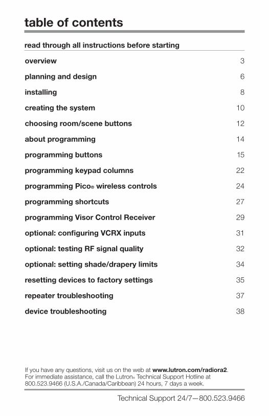
table of contents
read through all instructions before starting
overview 3
planning and design 6
installing 8
creating the system 10
choosing room/scene buttons 12
about programming 14
programming buttons 15
programming keypad columns 22
programming Pico® wireless controls 24
programming shortcuts 27
programming Visor Control Receiver 29
optional: configuring VCRX inputs 31
optional: testing RF signal quality 32
optional: setting shade/drapery limits 34
resetting devices to factory settings 35
repeater troubleshooting 37
device troubleshooting 38
Technical Support 24/7—800.523.9466
If you have any questions, visit us on the web at www.lutron.com/radiora2. For immediate assistance, call the LutronR Technical Support Hotline at 800.523.9466 (U.S.A./Canada/Caribbean) 24 hours, 7 days a week.
www.lutron.com/radiora2 Lutron® | 3
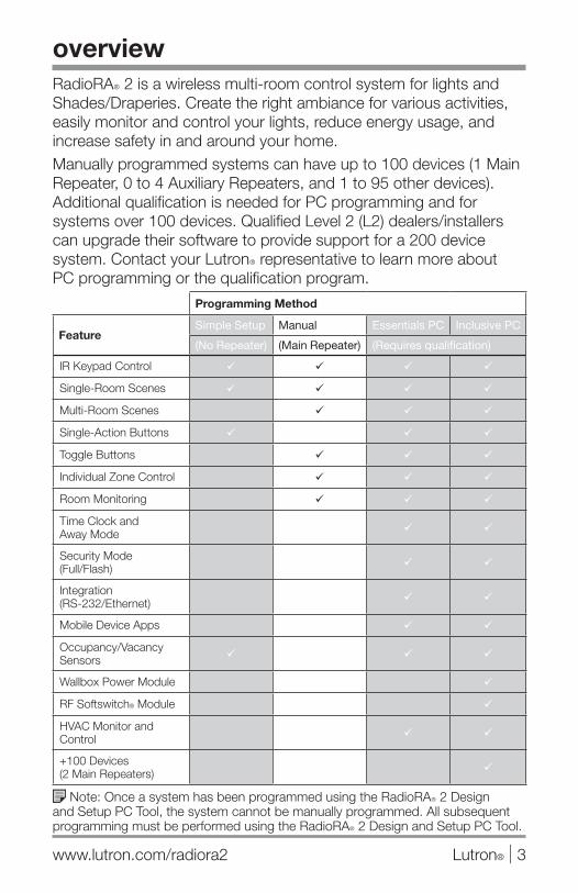
Note: Once a system has been programmed using the RadioRAR 2 Design and Setup PC Tool, the system cannot be manually programmed. All subsequent programming must be performed using the RadioRAR 2 Design and Setup PC Tool.
overview
Programming Method
FeatureSimple Setup Manual Essentials PC Inclusive PC
(No Repeater) (Main Repeater) (Requires qualification)
IR Keypad Control
Single-Room Scenes
Multi-Room Scenes
Single-Action Buttons
Toggle Buttons
Individual Zone Control
Room Monitoring
Time Clock and Away Mode
Security Mode (Full/Flash)
Integration (RS-232/Ethernet)
Mobile Device Apps
Occupancy/Vacancy Sensors
Wallbox Power Module
RF Softswitch® Module
HVAC Monitor and Control
+100 Devices (2 Main Repeaters)
RadioRAR 2 is a wireless multi-room control system for lights and Shades/Draperies. Create the right ambiance for various activities, easily monitor and control your lights, reduce energy usage, and increase safety in and around your home. Manually programmed systems can have up to 100 devices (1 Main Repeater, 0 to 4 Auxiliary Repeaters, and 1 to 95 other devices). Additional qualification is needed for PC programming and for systems over 100 devices. Qualified Level 2 (L2) dealers/installers can upgrade their software to provide support for a 200 device system. Contact your LutronR representative to learn more about PC programming or the qualification program.

24/7 Technical Support—800.523.94664 | Lutron®
manual programming system components*
Main Repeater Supports system setup, allows integration and PC connectivity (ethernet, RS-232), and ensures error-free communication between system components.
Auxiliary Repeater Extends RF coverage to ensure error-free communication between system components.
Dimmer/Switch Replaces a standard light switch. Dimmers allows smooth transitions of light and create unique lighting environments.
seeTouch® Keypad Wall-Mount—controls lights and Shades / Draperies throughout the home.
Tabletop—convenient, portable control of lights and Shades/Draperies throughout the home.
Pico® Wireless Control Battery-powered, retrofit, portable Keypad for convenient control of lights and Shades/Draperies throughout the home.
Plug-In Module
Lamp Dimmer
overview
Dimmer
Main Repeater
Auxiliary Repeater
Switch
seeTouchR Wall-Mount Keypad
seeTouchR Tabletop Keypad
PicoR Wireless Control
* some systems do not require every component listed
120 V 50 / 60 HzRR-3PD-1
®COOPERSBURG, PA 18036 USA
I H 300 VA /200 W300 W
LUTRON LUTRON
Setup
WiredRF
Communication
Repeater Status1 3 42 M
Power Repeater LinkCO
M9 V
1
N / C
MU
X
MU
X
2 3 4
AddTest
USB
Integrate Program / Integrate
RS232 Ethernet
Main Repeater
AddTest
Setup
WiredRF
Communication
Repeater Status1 3 42 M
Auxiliary Repeater
Power Repeater LinkCO
M9 V
1
N / C
MU
X
MU
X
2 3 4
AddTest
Shade
Open
Close

www.lutron.com/radiora2 Lutron® | 5
overview
Hybrid Keypad Replaces a standard light switch for dimming control. Buttons control lights and Shades/Draperies locally and throughout the home.
Visor Control Transmitter Controls lights throughout the home from the comfort of your car.
Visor Control Receiver Receives signal from Visor Control Transmitter and transmits to the entire RadioRAR 2 system.
GRAFIK Eye® QS Wireless Unit Powers and controls up to six zones of lights and up to 3 zones of Shades/ Draperies in a room.
Wireless Shade/Drapery Allows quiet, precise control of daylight.
manual programming system components* (continued)
Visor Control Transmitter
Visor Control Receiver
* some systems do not require every component listed
GRAFIK EyeR QS Wireless Unit
SivoiaR QS Wireless Shade/Drapery
Hybrid Keypad
SivoiaR QS TriathalonR
Shade
24/7 Technical Support—800.523.94666 | Lutron®
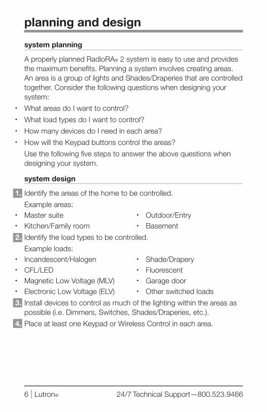
planning and design
system planning
A properly planned RadioRA® 2 system is easy to use and provides the maximum benefits. Planning a system involves creating areas. An area is a group of lights and Shades/Draperies that are controlled together. Consider the following questions when designing your system:
• What areas do I want to control?• What load types do I want to control?• How many devices do I need in each area?• How will the Keypad buttons control the areas?
Use the following five steps to answer the above questions when designing your system.
system design
1. Identify the areas of the home to be controlled.
Example areas:• Master suite• Kitchen/Family room
2. Identify the load types to be controlled.
Example loads:• Incandescent/Halogen• CFL/LED• Magnetic Low Voltage (MLV)• Electronic Low Voltage (ELV)
3. Install devices to control as much of the lighting within the areas as possible (i.e. Dimmers, Switches, Shades/Draperies, etc.).
4. Place at least one Keypad or Wireless Control in each area.
• Outdoor/Entry• Basement
• Shade/Drapery• Fluorescent• Garage door• Other switched loads
www.lutron.com/radiora2 Lutron® | 7
planning and design
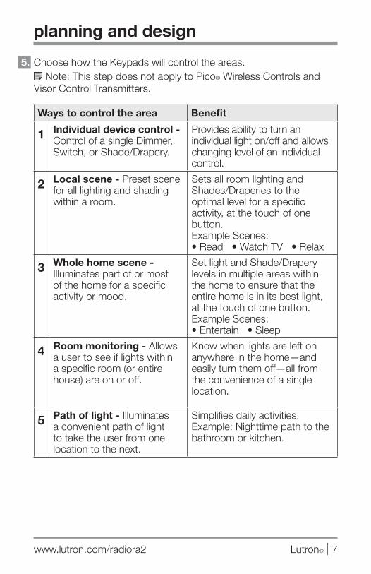
5. Choose how the Keypads will control the areas. Note: This step does not apply to Pico® Wireless Controls and
Visor Control Transmitters.
Ways to control the area Benefit
1 Individual device control - Control of a single Dimmer, Switch, or Shade/Drapery.
Provides ability to turn an individual light on/off and allows changing level of an individual control.
2 Local scene - Preset scene for all lighting and shading within a room.
Sets all room lighting and Shades/Draperies to the optimal level for a specific activity, at the touch of one button. Example Scenes: • Read • Watch TV • Relax
3 Whole home scene - Illuminates part of or most of the home for a specific activity or mood.
Set light and Shade/Drapery levels in multiple areas within the home to ensure that the entire home is in its best light, at the touch of one button. Example Scenes:• Entertain • Sleep
4 Room monitoring - Allows a user to see if lights within a specific room (or entire house) are on or off.
Know when lights are left on anywhere in the home—and easily turn them off—all from the convenience of a single location.
5 Path of light - Illuminates a convenient path of light to take the user from one location to the next.
Simplifies daily activities. Example: Nighttime path to the bathroom or kitchen.
24/7 Technical Support—800.523.94668 | Lutron®
installing
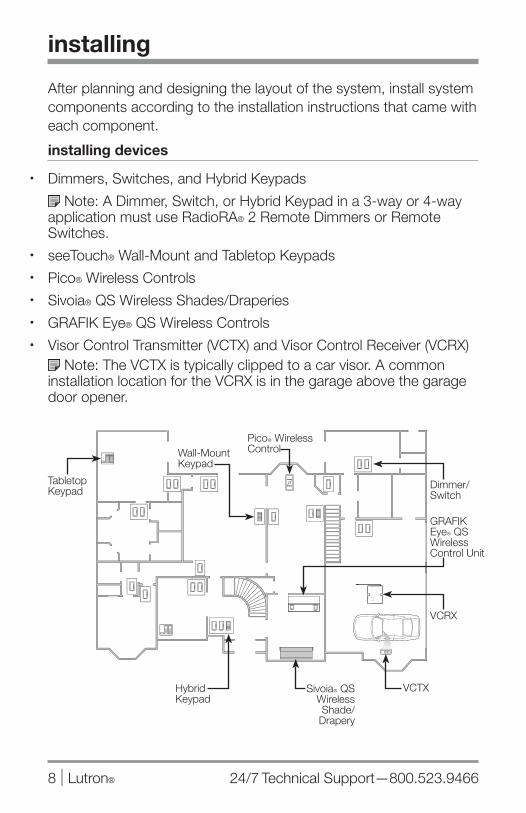
After planning and designing the layout of the system, install system components according to the installation instructions that came with each component.
installing devices
• Dimmers, Switches, and Hybrid Keypads
Note: A Dimmer, Switch, or Hybrid Keypad in a 3-way or 4-way application must use RadioRA® 2 Remote Dimmers or Remote Switches.
• seeTouch® Wall-Mount and Tabletop Keypads• Pico® Wireless Controls• Sivoia® QS Wireless Shades/Draperies• GRAFIK Eye® QS Wireless Controls• Visor Control Transmitter (VCTX) and Visor Control Receiver (VCRX)
Note: The VCTX is typically clipped to a car visor. A common installation location for the VCRX is in the garage above the garage door opener.
Dimmer/ Switch
Wall-Mount Keypad
VCRX
GRAFIK EyeR QS Wireless Control Unit
VCTXSivoiaR QS Wireless Shade/Drapery
Tabletop Keypad
PicoR Wireless Control
Hybrid Keypad
www.lutron.com/radiora2 Lutron® | 9
installing
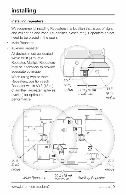
installing repeaters
We recommend installing Repeaters in a location that is out of sight and will not be disturbed (i.e. cabinet, closet, etc.). Repeaters do not need to be placed in the open.
• Main Repeater• Auxiliary Repeater
All devices must be located within 30 ft (9 m) of a Repeater. Multiple Repeaters may be necessary to provide adequate coverage.
When using two or more Repeaters, position each Repeater within 60 ft (18 m) of another Repeater (spheres overlap) for optimum performance.
30 ft (9 m)radius
30 ft (9 m)
radius
60 ft (18 m) maximum
60 ft (18 m) maximum
Main Repeater Auxiliary Repeater
30 ft (9 m) radius
30 ft (9 m) radius
Setup
WiredRF
Communication
Repeater Status1 3 42 M
Power Repeater LinkCO
M9 V
1
N / C
MU
X
MU
X
2 3 4
AddTest
USB
Integrate Program / Integrate
RS232 Ethernet
Main Repeater
AddTest
Setup
WiredRF
Communication
Repeater Status1 3 42 M
Auxiliary Repeater
Power Repeater LinkCO
M9 V
1
N / C
MU
X
MU
X
2 3 4
AddTest
Setup
WiredRF
Communication
Repeater Status1 3 42 M
Power Repeater LinkCOM9 V
1
N / C
MUX
MUX
2 3 4
AddTest
USB
Integrate Program / Integrate
RS232 Ethernet
Main Repeater
AddTest
Setup
WiredRF
Communication
Repeater Status1 3 42 M
Auxiliary Repeater
Power Repeater LinkCOM9 V
1
N / C
MUX
MUX
2 3 4
AddTest

24/7 Technical Support—800.523.946610 | Lutron®
creating the system
system setup
To set up a RadioRA® 2 system, components must be added to the Main Repeater. First, add Auxiliary Repeater(s)*; then add all other system devices.
adding Auxiliary Repeaters and devices
1. Enter Add Mode
Press and hold the Add button on the Main Repeater for 3 seconds until the green Add LED begins to rapid-flash (ten times per second) and the Repeater beeps. Wait 10 seconds.
After the green Add LED begins to normal-flash (once per second) the system is in Add Mode and is ready to add new components.
Note: The first time Add Mode is entered on a Main Repeater, it will create a new system with a unique system address.
2. Add Auxiliary Repeater(s)*
Press and hold the Add button on an Auxiliary Repeater for 3 seconds until the green Add LED begins to rapid-flash.
Note: If the system does NOT require Auxiliary Repeater(s), skip ahead to step 3.
When an Auxiliary Repeater has been added successfully, the Main Repeater will beep once and the Add LED on the Auxiliary Repeater will normal-flash. The Repeater Status LEDs corresponding to the Auxiliary Repeater that was added will also turn on.
To add another Auxiliary Repeater (4 Auxiliary Repeaters maximum), repeat step 2.
* Auxiliary Repeater(s) are required when devices extend beyond the range of the Main Repeater
If a device does not respond as described, consult the troubleshooting section.
Main Repeater
Setup
WiredRF
Communication
Repeater Status1 3 42 M
Power Repeater LinkCO
M9 V
1
N / C
MU
X
MU
X
2 3 4
AddTest
USB
Integrate Program / Integrate
RS232 Ethernet
Main Repeater

www.lutron.com/radiora2 Lutron® | 11
creating the system
3. Add devices When a device has been successfully added, the Repeater will beep.
4. Exit Add Mode
Press and hold the Add button on any Repeater for 3 seconds until the Add LED begins to rapid-flash. After the LED turns off (can take up to 60 seconds), system has exited Add Mode.
Note: To remove an individual device from the system, consult the resetting devices to factory settings section.
Press and hold any button except raise/lower or Learn (press and release the OK button on a GRAFIK Eye® QS Wireless unit) for 3 seconds until all LEDs normal-flash. Devices with outputs (i.e. Dimmer) will turn the load on/off 3 times to indicate the device has been successfully added.
Press and hold any button for 3 seconds, until the green LED rapid-flashes for 2 seconds, then normal-flashes.
Press and hold the bottom button for 6 to 8 seconds.
Pico® Wireless Control
Check LED feedback on devices:• Slow-flash (3 seconds on, 1 second off)—device not added to system.• Normal-flash (once per second)—device is added to system.• No flash—device not communicating properly with Repeater. Consult
the troubleshooting section.
SivoiaR QS Wireless Shades/Draperies
Tabletop Keypads must be plugged in during set up and programming.
TriathalonR Shades
Press and hold the Shade button for 5 seconds until the green LED rapid-flashes for 2 seconds, then normal-flashes.
Wait up to 60 seconds until the Shade LED slow flashes before adding.
LUTRONLUTRON
LUTRONLUTRON
LUTRONLUTRON
LUTRONLUTRON

24/7 Technical Support—800.523.946612 | Lutron®
Keypad button LEDs can be configured to show the status of the lights or Shades/Draperies programmed to the Keypad button. They can be configured to provide Room Status (default) or Scene Status.
Room Status * Scene Status
Button LED is on when at least one of the devices assigned to the button is on at any level.
Button LED is only on when all of the devices assigned to the button are at exactly their programmed level.
ways to control the area ways to control the area
Individual device control - Control of a single Dimmer, Switch, or Shade/Drapery.Room monitoring - Allows a user to see if lights within a specific room are on or off.
Local scene - Preset scene for all lighting and shading within a room.Whole home scene - Illuminates part of or most of the home for a specific activity or mood.Path of light - Illuminates a convenient path of light to take the user from one location to the next.
common applications common applications
Bedside Keypad: Press the “Basement” button to verify the basement lights are off and the “Hall” button to make sure the hall light is left on at night.
Wall-Mount Keypad: Press the “Entertain” button to set the light levels in common areas of the home for entertaining guests.Bedside Keypad: Press the “Pathway” button to illuminate a soft path of light from the bedroom to the bathroom at night.
choosing room/scene buttons
Best Practice: The top button on a Keypad should create the brightest lighting scene – with each button below creating progressively lower light levels. The bottom button should be very low or off.
Best Practice: Use a consistent programming method on all of the Keypads.
* Shades / Draperies do not have an “off” state. Adding them to a Room Status button will result in unpredictable behavior. Use Scene Status buttons to control Shades / Draperies.

www.lutron.com/radiora2 Lutron® | 13
choosing room/scene buttons
button configuration
1. Enter Button Configuration
2. Configure each button as Scene or Room Status
Press and release desired button to toggle configuration between Scene and Room Status.
By default, all buttons are set to Room Status, indicated by the LEDs normal-flashing.
3. Exit Button Configuration
Press and hold the top 3 buttons of rightmost column (top 2 buttons on RRD-W2RLD Keypad and VCRX Keypad column) until all LEDs turn off (3 to 6 seconds).
LED StatusNormal-flash Room (default)On solid Scene
Press and hold the top 2 buttons for 6 seconds, until all LEDs turn on (solid or flashing).
RRD-W2RLD Keypads
Press and hold the top 2 buttons in the Keypad column for 3 seconds, until all LEDs turn on (solid or flashing).
VCRXOnly the “Keypad” column can be configured on the Receiver.
Press and hold the top 3 buttons in rightmost column for 3 seconds, until all LEDs turn on (solid or flashing).
All other Keypads* (including Hybrid Keypads) Tabletop Keypads
must be plugged in during set up and programming.
*Does not apply to Pico® Wireless Controls.
24/7 Technical Support—800.523.946614 | Lutron®
about programming
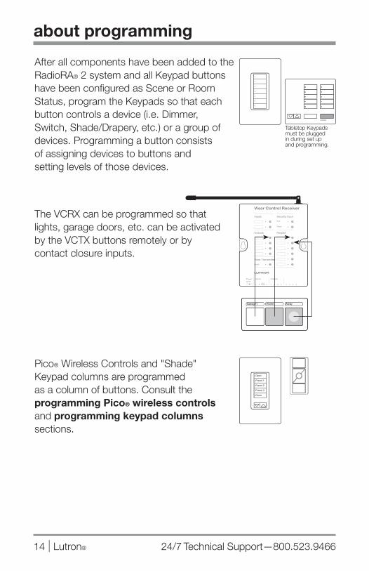
After all components have been added to the RadioRA® 2 system and all Keypad buttons have been configured as Scene or Room Status, program the Keypads so that each button controls a device (i.e. Dimmer, Switch, Shade/Drapery, etc.) or a group of devices. Programming a button consists of assigning devices to buttons and setting levels of those devices.
The VCRX can be programmed so that lights, garage doors, etc. can be activated by the VCTX buttons remotely or by contact closure inputs.
Pico® Wireless Controls and "Shade" Keypad columns are programmed as a column of buttons. Consult the programming Pico® wireless controls and programming keypad columns sections.
Tabletop Keypads must be plugged in during set up and programming.
Garage1 Home Away
Shade
Open
Close

www.lutron.com/radiora2 Lutron® | 15
programming buttons
1. Enter Program Mode
Press and hold the top and bottom buttons of the rightmost column (top 2 buttons on RRD-W2RLD Keypad and VCRX Keypad column) for 3 seconds until the top button LED begins to normal-flash.
2. Select the button to program
Press and release the button to be programmed.
Note: The top button in the column will be selected by default, indicated by the top button LED normal-flashing. To program a different button, press and release the desired button.
Note: Raise/lower buttons cannot be programmed.
Note: If the All On button on a Tabletop Keypad is selected, all the LEDs on the Tabletop Keypad will scroll up. If the All Off button is selected, all the LEDs will scroll down.
Note: The VCRX Keypad and Inputs buttons can be programed but the VCRX Security Input buttons can not be programmed in manually programmed systems.
24/7 Technical Support—800.523.946616 | Lutron®
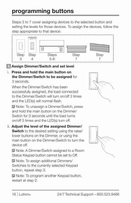
Steps 3 to 7 cover assigning devices to the selected button and setting the levels for those devices. To assign the devices, follow the step appropriate to that device:
3. Assign Dimmer/Switch and set level
i. Press and hold the main button on the Dimmer/Switch to be assigned for 3 seconds.
When the Dimmer/Switch has been successfully assigned, the load connected to the Dimmer/Switch will turn on/off 3 times and the LED(s) will normal-flash.
Note: To unassign a Dimmer/Switch, press and hold the main button on the Dimmer/Switch for 3 seconds until the load turns on/off 3 times and the LED(s) turn off.
ii. Adjust the level of the assigned Dimmer/Switch to the desired setting using the raise/lower buttons on the Dimmer, or using the main button on the Dimmer/Switch to turn the device off.
Note: A Dimmer/Switch assigned to a Room Status Keypad button cannot be set to Off.
Note: To assign additional Dimmers/Switches to the currently selected Keypad button, repeat step 3.
Note: To program another Keypad button, restart at step 2.
programming buttons
Step 3
Step 7
Steps 5-6
Step 4
Hybrid
Step 7
LUTRON
LUTRON
LUTRON
www.lutron.com/radiora2 Lutron® | 17
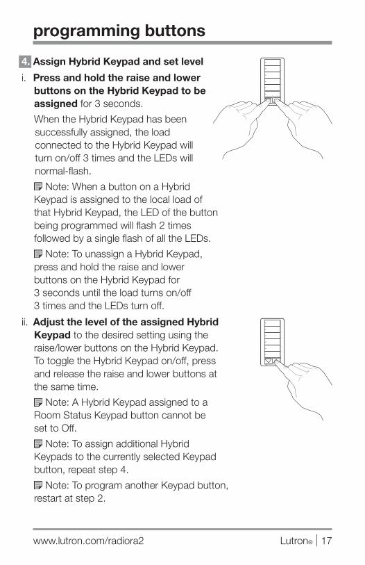
4. Assign Hybrid Keypad and set level
i. Press and hold the raise and lower buttons on the Hybrid Keypad to be assigned for 3 seconds.
When the Hybrid Keypad has been successfully assigned, the load connected to the Hybrid Keypad will turn on/off 3 times and the LEDs will normal-flash.
Note: When a button on a Hybrid Keypad is assigned to the local load of that Hybrid Keypad, the LED of the button being programmed will flash 2 times followed by a single flash of all the LEDs.
Note: To unassign a Hybrid Keypad, press and hold the raise and lower buttons on the Hybrid Keypad for 3 seconds until the load turns on/off 3 times and the LEDs turn off.
ii. Adjust the level of the assigned Hybrid Keypad to the desired setting using the raise/lower buttons on the Hybrid Keypad. To toggle the Hybrid Keypad on/off, press and release the raise and lower buttons at the same time.
Note: A Hybrid Keypad assigned to a Room Status Keypad button cannot be set to Off.
Note: To assign additional Hybrid Keypads to the currently selected Keypad button, repeat step 4.
Note: To program another Keypad button, restart at step 2.
programming buttons
24/7 Technical Support—800.523.946618 | Lutron®
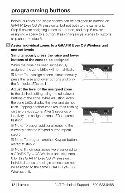
Individual zones and single scenes can be assigned to buttons on GRAFIK Eye® QS Wireless units, but not both to the same unit. Step 5 covers assigning zones to a button, and step 6 covers assigning a scene to a button. If assigning single scenes to buttons, skip ahead to step 6.
5. Assign individual zones to a GRAFIK Eye® QS Wireless unit and set levels
i. Simultaneously press the raise and lower buttons of the zone to be assigned.
When the zone has been successfully assigned, the zone LEDs will normal-flash.
Note: To unassign a zone, simultaneously press the raise and lower buttons until only the 3 middle LEDs are lit.
ii. Adjust the level of the assigned zone to the desired setting using the raise/lower buttons of the zone. While adjusting levels, the zone LEDs display the level and do not flash. Tapping another zone resumes flashing on the previous zone. After 3 seconds of inactivity, the assigned zone LEDs resume flashing.
Note: To assign additional zones to the currently selected Keypad button repeat step 5.
Note: To program another Keypad button, restart at step 2.
Note: If individual zones were assigned to a GRAFIK Eye® QS Wireless unit, skip step 6 for this GRAFIK Eye® QS Wireless unit. Individual zones and single scenes can not be assigned to the same GRAFIK Eye® QS Wireless unit.
programming buttons
www.lutron.com/radiora2 Lutron® | 19
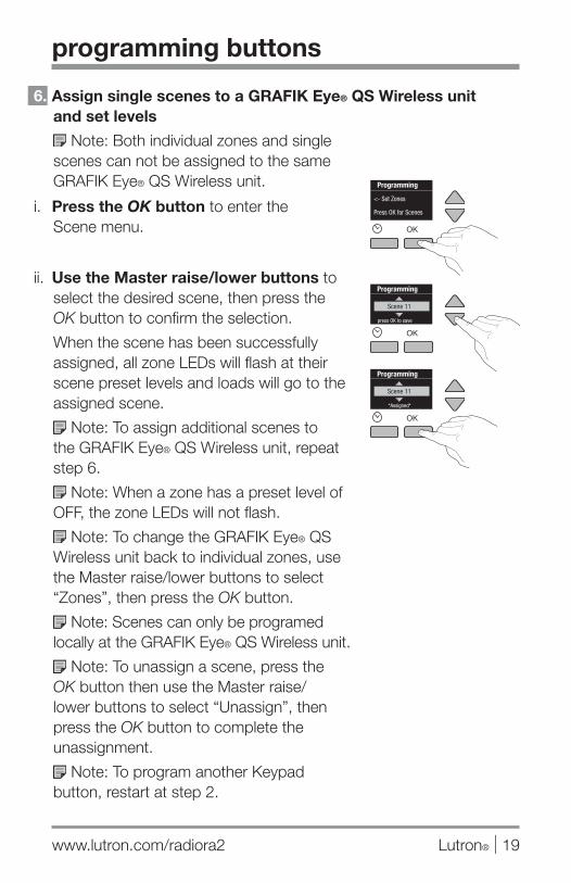
6. Assign single scenes to a GRAFIK Eye® QS Wireless unit and set levels
Note: Both individual zones and single scenes can not be assigned to the same GRAFIK Eye® QS Wireless unit.
i. Press the OK button to enter the Scene menu.
ii. Use the Master raise/lower buttons to select the desired scene, then press the OK button to confirm the selection.
When the scene has been successfully assigned, all zone LEDs will flash at their scene preset levels and loads will go to the assigned scene.
Note: To assign additional scenes to the GRAFIK Eye® QS Wireless unit, repeat step 6.
Note: When a zone has a preset level of OFF, the zone LEDs will not flash.
Note: To change the GRAFIK Eye® QS Wireless unit back to individual zones, use the Master raise/lower buttons to select “Zones”, then press the OK button.
Note: Scenes can only be programed locally at the GRAFIK Eye® QS Wireless unit.
Note: To unassign a scene, press the OK button then use the Master raise/lower buttons to select “Unassign”, then press the OK button to complete the unassignment.
Note: To program another Keypad button, restart at step 2.
programming buttons
24/7 Technical Support—800.523.946620 | Lutron®
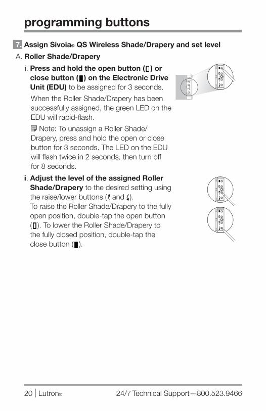
7. Assign Sivoia® QS Wireless Shade/Drapery and set level
A. Roller Shade/Drapery
i. Press and hold the open button ( ) or close button ( ) on the Electronic Drive Unit (EDU) to be assigned for 3 seconds.
When the Roller Shade/Drapery has been successfully assigned, the green LED on the EDU will rapid-flash.
Note: To unassign a Roller Shade/Drapery, press and hold the open or close button for 3 seconds. The LED on the EDU will flash twice in 2 seconds, then turn off for 8 seconds.
ii. Adjust the level of the assigned Roller Shade/Drapery to the desired setting using the raise/lower buttons ( and ). To raise the Roller Shade/Drapery to the fully open position, double-tap the open button ( ). To lower the Roller Shade/Drapery to the fully closed position, double-tap the close button ( ).
programming buttons
www.lutron.com/radiora2 Lutron® | 21
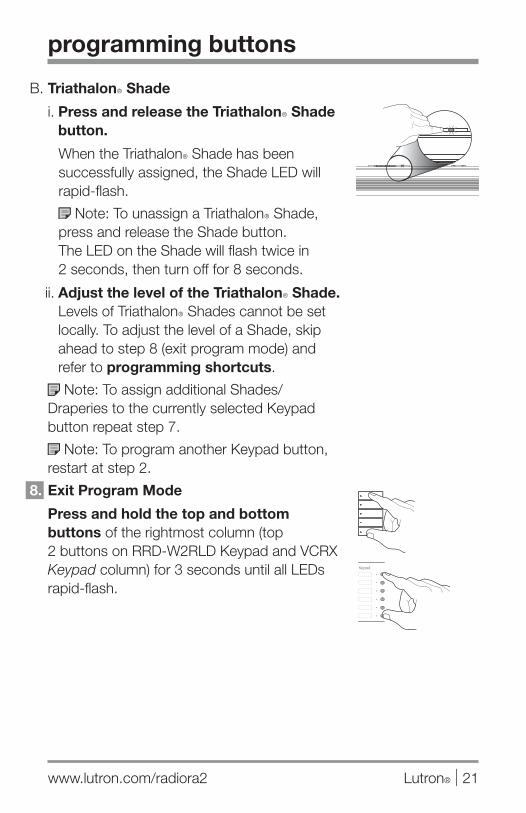
B. TriathalonR Shade
i. Press and release the TriathalonR Shade button.
When the TriathalonR Shade has been successfully assigned, the Shade LED will rapid-flash.
Note: To unassign a TriathalonR Shade, press and release the Shade button. The LED on the Shade will flash twice in 2 seconds, then turn off for 8 seconds.
ii. Adjust the level of the TriathalonR Shade. Levels of TriathalonR Shades cannot be set locally. To adjust the level of a Shade, skip ahead to step 8 (exit program mode) and refer to programming shortcuts.
Note: To assign additional Shades/Draperies to the currently selected Keypad button repeat step 7.
Note: To program another Keypad button, restart at step 2.
8. Exit Program Mode
Press and hold the top and bottom buttons of the rightmost column (top 2 buttons on RRD-W2RLD Keypad and VCRX Keypad column) for 3 seconds until all LEDs rapid-flash.
programming buttons
24/7 Technical Support—800.523.946622 | Lutron®
programming keypad columns
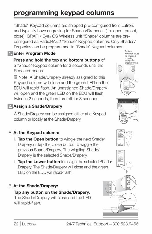
"Shade" Keypad columns are shipped pre-configured from Lutron, and typically have engraving for Shades/Draperies (i.e. open, preset, close). GRAFIK Eye® QS Wireless unit "Shade" columns are pre-configured as RadioRA® 2 "Shade" Keypad columns. Only Shades/Draperies can be programmed to "Shade" Keypad columns.
1. Enter Program Mode
Press and hold the top and bottom buttons of a "Shade" Keypad column for 3 seconds until the Repeater beeps.
Note: A Shade/Drapery already assigned to this Keypad column will close and the green LED on the EDU will rapid-flash. An unassigned Shade/Drapery will open and the green LED on the EDU will flash twice in 2 seconds, then turn off for 8 seconds.
2. Assign a Shade/Drapery
A A Shade/Drapery can be assigned either at a Keypad column or locally at the Shade/Drapery.
A. At the Keypad column:
i. Tap the Open button to wiggle the next Shade/Drapery or tap the Close button to wiggle the previous Shade/Drapery. The wiggling Shade/Drapery is the selected Shade/Drapery.
ii. Tap the Lower button to assign the selected Shade/Drapery. The Shade/Drapery will close and the green LED on the EDU will rapid-flash.
B. At the Shade/Drapery:
Tap any button on the Shade/Drapery. The Shade/Drapery will close and the LED will rapid-flash.
Tabletop Keypads must be plugged in during set up and programming.

www.lutron.com/radiora2 Lutron® | 23
3. Set presets for Shades/Draperies
i. Tap the preset button you wish to program. Assigned devices will go to their preset level and the selected preset button LED will turn on solid.
ii. Tap the Open button to wiggle the next Shade/Drapery or tap the Close button to wiggle the previous Shade/Drapery. The wiggling Shade/Drapery is the selected Shade/Drapery.
iii. Press the raise or lower button to adjust the level of the Shade/Drapery.
iv. Press and hold the preset button for 3 seconds until the LED rapid-flashes to save the level of the Shade/Drapery.
Note: To program another preset button, repeat step 3.
Note: If any other preset button is pressed while a preset button is selected, the currently selected preset will not be saved.
Note: To cancel preset save, tap the selected preset button.
4. Exit Program Mode
Press and hold the top and bottom buttons of the selected Keypad column for 3 seconds until the Repeater beeps.
programming keypad columns
24/7 Technical Support—800.523.946624 | Lutron®
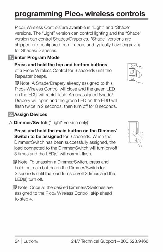
programming Pico® wireless controls
Pico® Wireless Controls are available in “Light” and “Shade” versions. The “Light” version can control lighting and the “Shade” version can control Shades/Draperies. "Shade" versions are shipped pre-configured from Lutron, and typically have engraving for Shades/Draperies.
1. Enter Program Mode
Press and hold the top and bottom buttons of a Pico® Wireless Control for 3 seconds until the Repeater beeps.
Note: A Shade/Drapery already assigned to this Pico® Wireless Control will close and the green LED on the EDU will rapid-flash. An unassigned Shade/Drapery will open and the green LED on the EDU will flash twice in 2 seconds, then turn off for 8 seconds.
2. Assign Devices
A. Dimmer/Switch ("Light" version only)
Press and hold the main button on the Dimmer/Switch to be assigned for 3 seconds. When the Dimmer/Switch has been successfully assigned, the load connected to the Dimmer/Switch will turn on/off 3 times and the LED(s) will normal-flash.
Note: To unassign a Dimmer/Switch, press and hold the main button on the Dimmer/Switch for 3 seconds until the load turns on/off 3 times and the LED(s) turn off.
Note: Once all the desired Dimmers/Switches are assigned to the Pico® Wireless Control, skip ahead to step 4.
LUTRON
Shade
Open
Close

www.lutron.com/radiora2 Lutron® | 25
B. Shade/Drapery ("Shade" version only)
A Shade/Drapery can be assigned either at a Pico® Wireless Control or locally at the Shade/Drapery.
a. At the Pico® Wireless Control:
i. Tap the Open button to wiggle the next Shade/Drapery or tap the Close button to wiggle the previous Shade/Drapery. The wiggling Shade/Drapery is the selected Shade/Drapery.
ii. Tap the Lower button to assign the selected Shade/Drapery. The Shade/Drapery will close and the green LED on the EDU will rapid-flash.
b. At the Shade/Drapery:
Tap any button on the Shade/Drapery. The Shade/Drapery will close and the green LED will rapid-flash.
programming Pico® wireless controls
Shade
Open
Close
Shade
Open
Close

24/7 Technical Support—800.523.946626 | Lutron®
programming Pico® wireless controls
3. Set presets for Shades/Draperies i. Tap the preset button you wish to program.
Assigned devices will go to their preset level.
ii. Tap the Open button to wiggle the next Shade/Drapery or tap the Close button to wiggle the previous Shade/Drapery. The wiggling Shade/Drapery is the selected Shade/Drapery.
iii. Press the raise or lower button to adjust the level of the Shade/Drapery.
iv. Press and hold the preset button for 3 seconds to save the level of the Shade/Drapery.
Note: If any other preset button is pressed while a preset button is selected, the currently selected preset will not be saved.
Note: To cancel preset save, tap the selected preset button.
4. Exit Program Mode
Press and hold the top and bottom buttons of the selected Pico® Wireless Control for 3 seconds until the Repeater beeps.
Note: To program another Pico® Wireless Control, repeat steps 1 to 4.
Shade
Open
Close
Shade
Open
Close
Shade
Open
Close
Shade
Open
Close
Shade
Open
Close

www.lutron.com/radiora2 Lutron® | 27
programming shortcuts
saving new levels on previously programmed Keypad buttons
1. Select Keypad button
Press and release the Keypad button to be programmed. Assigned devices will go to their preset level.
2. Adjust levels
Use raise, lower, or tapswitch to adjust the level of assigned devices.
Note: To raise/lower a Wireless Shade, use a "Shade" Keypad that has been assigned to that Shade.
3. Save levels
Press and hold the previously selected Keypad button for 6 to 8 seconds.
LUTRON
Shade
Open
Close
Shade
Open
Close
Shade
Open
Close
24/7 Technical Support—800.523.946628 | Lutron®
programming shortcuts
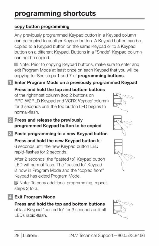
copy button programming
Any previously programmed Keypad button in a Keypad column can be copied to another Keypad button. A Keypad button can be copied to a Keypad button on the same Keypad or to a Keypad button on a different Keypad. Buttons in a "Shade" Keypad column can not be copied.
Note: Prior to copying Keypad buttons, make sure to enter and exit Program Mode at least once on each Keypad that you will be copying to. See steps 1 and 7 of programming buttons.
1. Enter Program Mode on a previously programmed Keypad
Press and hold the top and bottom buttons of the rightmost column (top 2 buttons on RRD-W2RLD Keypad and VCRX Keypad column) for 3 seconds until the top button LED begins to normal-flash.
2. Press and release the previously programmed Keypad button to be copied
3. Paste programming to a new Keypad button
Press and hold the new Keypad button for 6 seconds until the new Keypad button LED rapid-flashes for 2 seconds.
After 2 seconds, the “pasted to” Keypad button LED will normal-flash. The “pasted to” Keypad is now in Program Mode and the “copied from” Keypad has exited Program Mode.
Note: To copy additional programming, repeat steps 2 to 3.
4. Exit Program Mode
Press and hold the top and bottom buttons of last Keypad "pasted to" for 3 seconds until all LEDs rapid-flash.
www.lutron.com/radiora2 Lutron® | 29
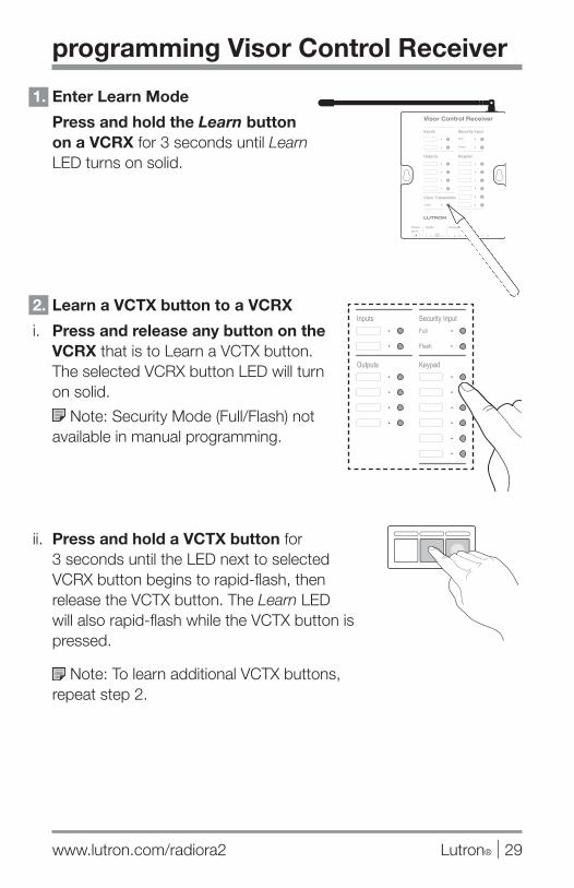
1. Enter Learn Mode
Press and hold the Learn button on a VCRX for 3 seconds until Learn LED turns on solid.
2. Learn a VCTX button to a VCRX
i. Press and release any button on the VCRX that is to Learn a VCTX button. The selected VCRX button LED will turn on solid.
Note: Security Mode (Full/Flash) not available in manual programming.
ii. Press and hold a VCTX button for 3 seconds until the LED next to selected VCRX button begins to rapid-flash, then release the VCTX button. The Learn LED will also rapid-flash while the VCTX button is pressed.
Note: To learn additional VCTX buttons, repeat step 2.
programming Visor Control Receiver

24/7 Technical Support—800.523.946630 | Lutron®
3. Exit Learn Mode
Press and release the Learn button on the VCRX until the Learn LED turns off.
Note: When the VCRX button has learned the VCTX button, the LED next to selected VCRX button will turn off when the VCTX button is released.
Note: To verify that the VCRX button has learned the VCTX button, press and release the VCTX button again. The LED next to the VCRX button will rapid-flash if the VCTX button was learned.
remove all VCTXs from the VCRX
To remove ALL VCTXs that have been learned to the VCRX, follow these steps:
i. Triple tap and hold the Learn button. DO NOT release the button after the third tap.
ii. Keep the button pressed on the third tap until the Learn LED starts to rapid-flash (approximately 3 seconds).
iii. Release the Learn button. Immediately (within 1/2 second) triple tap it again and release. The Learn LED will rapid-flash again. When the LED stops flashing, all VCTXs have been removed from the VCRX.
programming Visor Control Receiver
3X+
hold,then
3X
www.lutron.com/radiora2 Lutron® | 31
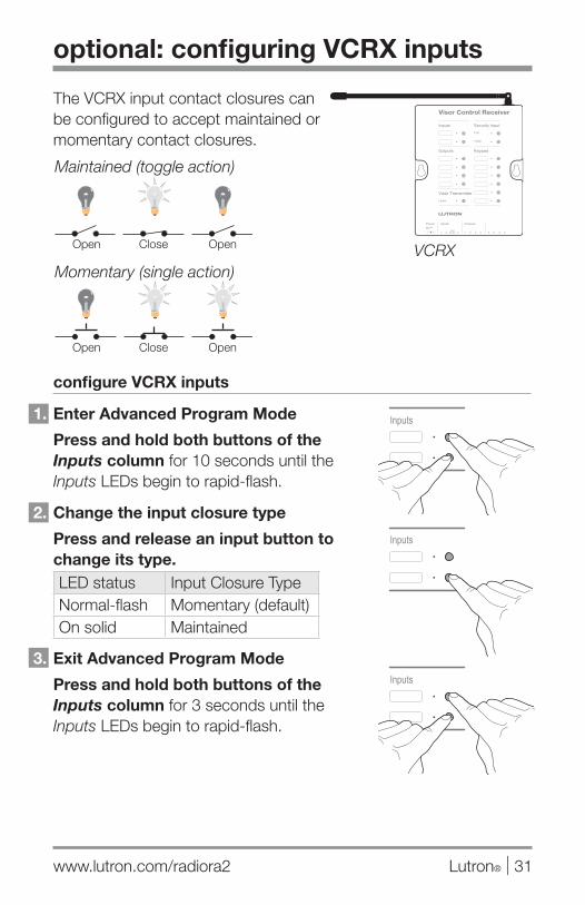
optional: configuring VCRX inputs
The VCRX input contact closures can be configured to accept maintained or momentary contact closures.
configure VCRX inputs
1. Enter Advanced Program Mode
Press and hold both buttons of the Inputs column for 10 seconds until the Inputs LEDs begin to rapid-flash.
2. Change the input closure type
Press and release an input button to change its type.LED status Input Closure TypeNormal-flash Momentary (default)On solid Maintained
3. Exit Advanced Program Mode
Press and hold both buttons of the Inputs column for 3 seconds until the Inputs LEDs begin to rapid-flash.
VCRXActivateSwitch
ReleaseSwitch
SwitchOpen
ActivateSwitch
ReleaseSwitch
SwitchOpen
Maintained (toggle action)
Open Close Open
Open Close Open
Momentary (single action)
24/7 Technical Support—800.523.946632 | Lutron®
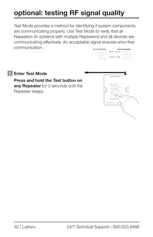
optional: testing RF signal quality
Test Mode provides a method for identifying if system components are communicating properly. Use Test Mode to verify that all Repeaters (in systems with multiple Repeaters) and all devices are communicating effectively. An acceptable signal ensures error-free communication.
1. Enter Test Mode
Press and hold the Test button on any Repeater for 3 seconds until the Repeater beeps.
Setup
WiredRF
Communication
Repeater Status1 3 42 M
Power Repeater LinkCO
M9 V
1
N / C
MU
X
MU
X
2 3 4
AddTest
USB
Integrate Program / Integrate
RS232 Ethernet
Main Repeater
Setup
WiredRF
Communication
Repeater Status1 3 42 M
Power Repeater LinkCO
M9 V
1
N / C
MU
X
MU
X
2 3 4
AddTest
USB
Integrate Program / Integrate
RS232 Ethernet
Main Repeater
www.lutron.com/radiora2 Lutron® | 33
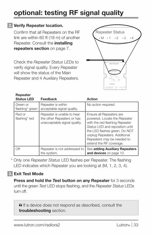
If a device does not respond as described, consult the troubleshooting section.
optional: testing RF signal quality
2. Verify Repeater location.
Confirm that all Repeaters on the RF link are within 60 ft (18 m) of another Repeater. Consult the installing repeaters section on page 7.
Check the Repeater Status LEDs to verify signal quality. Every Repeater will show the status of the Main Repeater and 4 Auxiliary Repeaters.
Repeater Status LED Feedback Action
Green or flashing* green
Repeater is within acceptable signal quality.
No action required.
Red or flashing* red
Repeater is unable to hear the other Repeaters or has unacceptable signal quality.
Ensure all Repeaters are powered. Locate the Repeater with the red flashing Repeater Status LED and reposition until the LED flashes green. Do NOT unplug Repeaters. Additional Repeaters may be needed to extend the RF coverage.
Off Repeater is not addressed to the system.
See adding Auxiliary Repeaters and devices on page 10.
* Only one Repeater Status LED flashes per Repeater. The flashing LED indicates which Repeater you are looking at (M, 1, 2, 3, 4).
3. Exit Test Mode
Press and hold the Test button on any Repeater for 3 seconds until the green Test LED stops flashing, and the Repeater Status LEDs turn off.
Setup
WiredRF
Communication
Repeater Status1 3 42 M
Power Repeater LinkCO
M9 V
1
N / C
MU
X
MU
X
2 3 4
AddTest
USB
Integrate Program / Integrate
RS232 Ethernet
Main Repeater
24/7 Technical Support—800.523.946634 | Lutron®
optional: setting shade/drapery limits
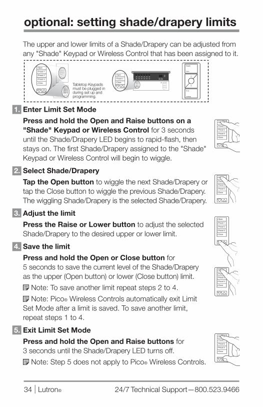
The upper and lower limits of a Shade/Drapery can be adjusted from any "Shade" Keypad or Wireless Control that has been assigned to it.
1. Enter Limit Set Mode
Press and hold the Open and Raise buttons on a "Shade" Keypad or Wireless Control for 3 seconds until the Shade/Drapery LED begins to rapid-flash, then stays on. The first Shade/Drapery assigned to the "Shade" Keypad or Wireless Control will begin to wiggle.
2. Select Shade/Drapery
Tap the Open button to wiggle the next Shade/Drapery or tap the Close button to wiggle the previous Shade/Drapery. The wiggling Shade/Drapery is the selected Shade/Drapery.
3. Adjust the limit
Press the Raise or Lower button to adjust the selected Shade/Drapery to the desired upper or lower limit.
4. Save the limit
Press and hold the Open or Close button for 5 seconds to save the current level of the Shade/Drapery as the upper (Open button) or lower (Close button) limit.
Note: To save another limit repeat steps 2 to 4.
Note: Pico® Wireless Controls automatically exit Limit Set Mode after a limit is saved. To save another limit, repeat steps 1 to 4.
5. Exit Limit Set Mode
Press and hold the Open and Raise buttons for 3 seconds until the Shade/Drapery LED turns off.
Note: Step 5 does not apply to Pico® Wireless Controls.
Tabletop Keypads must be plugged in during set up and programming.
Shade
Open
Close

www.lutron.com/radiora2 Lutron® | 35
resetting devices to factory settings
Resetting a device to factory settings will remove it from the system and will clear its programming. After being reset to factory settings, the device will need to be reprogrammed as part of a RadioRA® 2 system. To reset a device to factory settings, perform the steps below.
Dimmer, Switch, Keypad, Visor Control Receiver, Pico® Wireless Control, Triathalon® Shade, or Repeater
1. Triple tap and hold any button* on the device. DO NOT release the button after the third tap.
2. Keep the button pressed on the third tap until...
A. Dimmer: the Dimmer LEDs ramp up and down rapidly and the load flashes at the same rate.
B. Pico® Wireless Control: 6 to 8 seconds.
C. All other devices: the LED(s) start to rapid-flash (approximately 3 seconds).
3. Release the button and immediately (within 1/2 second) triple tap it again. Dimmers and Switches will normal-flash their loads. All other devices will rapid-flash their LED(s) again. When the load(s)/LED(s) stop flashing, the device has been reset to factory settings.
* Except raise, lower, or learn.
3X+
hold
3X
LUTRON
Setup
WiredRF
Communication
Repeater Status1 3 42 M
Power Repeater LinkCO
M9 V
1
N / C
MU
X
MU
X
2 3 4
AddTest
USB
Integrate Program / Integrate
RS232 Ethernet
Main Repeater
Shade
Open
Close
24/7 Technical Support—800.523.946636 | Lutron®
resetting devices to factory settings
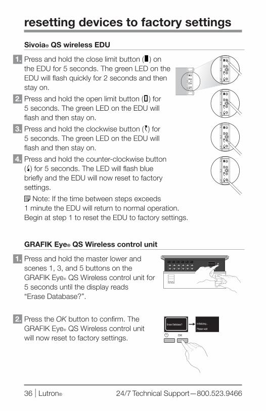
Sivoia® QS wireless EDU
1. Press and hold the close limit button ( ) on the EDU for 5 seconds. The green LED on the EDU will flash quickly for 2 seconds and then stay on.
2. Press and hold the open limit button ( ) for 5 seconds. The green LED on the EDU will flash and then stay on.
3. Press and hold the clockwise button ( ) for 5 seconds. The green LED on the EDU will flash and then stay on.
4. Press and hold the counter-clockwise button ( ) for 5 seconds. The LED will flash blue briefly and the EDU will now reset to factory settings.
Note: If the time between steps exceeds 1 minute the EDU will return to normal operation. Begin at step 1 to reset the EDU to factory settings.
GRAFIK Eye® QS Wireless control unit
1. Press and hold the master lower and scenes 1, 3, and 5 buttons on the GRAFIK EyeR QS Wireless control unit for 5 seconds until the display reads “Erase Database?”.
2. Press the OK button to confirm. The GRAFIK EyeR QS Wireless control unit will now reset to factory settings.
www.lutron.com/radiora2 Lutron® | 37
repeater troubleshooting
Symptom Possible Cause Remedy
Cre
atin
g t
he S
yste
m
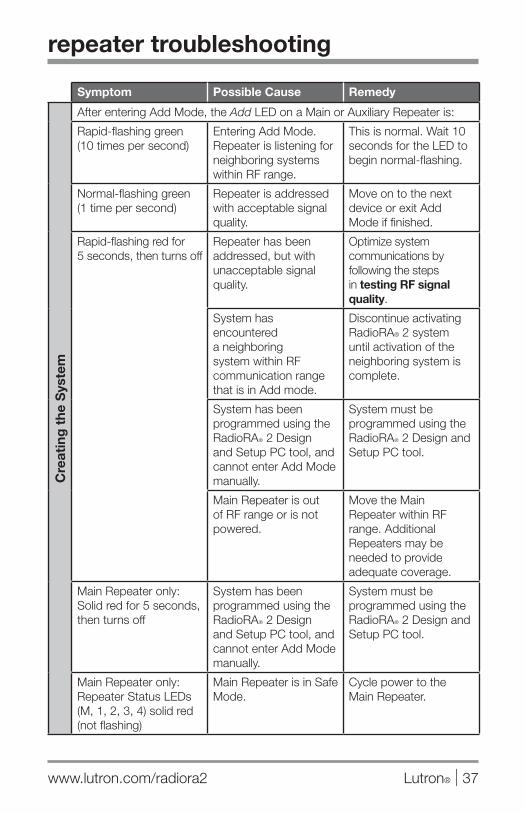
After entering Add Mode, the Add LED on a Main or Auxiliary Repeater is:
Rapid-flashing green (10 times per second)
Entering Add Mode. Repeater is listening for neighboring systems within RF range.
This is normal. Wait 10 seconds for the LED to begin normal-flashing.
Normal-flashing green (1 time per second)
Repeater is addressed with acceptable signal quality.
Move on to the next device or exit Add Mode if finished.
Rapid-flashing red for 5 seconds, then turns off
Repeater has been addressed, but with unacceptable signal quality.
Optimize system communications by following the steps in testing RF signal quality.
System has encountered a neighboring system within RF communication range that is in Add mode.
Discontinue activating RadioRA® 2 system until activation of the neighboring system is complete.
System has been programmed using the RadioRAR 2 Design and Setup PC tool, and cannot enter Add Mode manually.
System must be programmed using the RadioRAR 2 Design and Setup PC tool.
Main Repeater is out of RF range or is not powered.
Move the Main Repeater within RF range. Additional Repeaters may be needed to provide adequate coverage.
Main Repeater only: Solid red for 5 seconds, then turns off
System has been programmed using the RadioRAR 2 Design and Setup PC tool, and cannot enter Add Mode manually.
System must be programmed using the RadioRAR 2 Design and Setup PC tool.
Main Repeater only: Repeater Status LEDs (M, 1, 2, 3, 4) solid red (not flashing)
Main Repeater is in Safe Mode.
Cycle power to the Main Repeater.

24/7 Technical Support—800.523.946638 | Lutron®
device troubleshooting
Symptom Possible Cause Remedy
Cre
atin
g t
he S
yste
m
After attempting to add a device, the Repeaters beep 3 times.
The system is out of device addresses.
If the system has less than the maximum number of devices, use the RadioRA® 2 Design and Setup PC Tool to recover missing device addresses.
While attempting to add a Keypad, the Keypad LEDs rapid-flash for approximately 5 seconds then go out.
Keypad is out of RF range of the closest Repeater.
Move a Repeater closer to the device in question. Additional Repeaters may be needed to provide adequate coverage.
System not in Add Mode.
Place system in Add Mode.
While attempting to add a device, the LEDs do not slow flash.
Device is out of RF range of the closest Repeater.
Move a Repeater closer to the device in question. Additional Repeaters may be needed to provide adequate coverage.
Device may be part of another system.
If the device should be in this system, reset the device to factory settings. Follow the steps in resetting devices to factory settings.
TriathalonR Shades only: It may take up to 60 seconds before a TriathalonR Shade LED begins to flash.
Wait up to 60 seconds until the Shade LED slow flashes before adding.

www.lutron.com/radiora2 Lutron® | 39
Symptom Possible Cause Remedy
Pro
gra
mm
ing
But
tons
After entering Program Mode, LEDs on a Keypad, Dimmer/Switch, or other device are not normal-flashing.
Device has not been assigned to a button.
Assign the device to a button following the instructions starting at step 2 in programming buttons.
When attempting to assign a Dimmer/Switch to a Keypad button, the load connected to the Dimmer/Switch does not turn on/off 3 times and the LED(s) do not normal-flash.
Dimmer/Switch has not been added to the system.
Add the Dimmer/Switch to the system following the steps in adding auxiliary repeaters and devices.
Pro
gra
mm
ing
VC
RX After entering Program
Mode, LEDs on a VCRX, Dimmer/Switch, or other device are not normal-flashing.
Device has not been assigned to a VCRX button.
Assign the device to a VCRX button following the instructions starting at step 2 in programming buttons.
device troubleshooting

Worldwide Technical and Sales Assistance
If you have questions concerning the installation or operation of this product, visit us on the web at www.lutron.com/radiora2 or call the Lutron Technical Support Center.
Please provide the exact model number when calling.Model number can be found on the product packaging.Example: RRD-6CL
U.S.A., Canada, and the Caribbean: 800.523.9466Mexico: +1.888.235.2910Other countries: +1.610.282.3800
Lutron, RadioRA, Sivoia, GRAFIK Eye, seeTouch, Pico, Triathalon, Softwitch, and are registered trademarks and RadioRA 2 is a trademark of Lutron Electronics Co., Inc.
Lutron Electronics Co., Inc.7200 Suter RoadCoopersburg, PA 18036
P/N 044331Rev. A
© 12/2013 Lutron Electronics Co., Inc.