radion transmitter ref guide - bosch...
TRANSCRIPT
RADIONTransmitter
en Reference Guide


Table of contents
1 Transmitter introduction 51.1 About documentation 51.2 Bosch Security Systems, Inc product manufacturing dates 51.3 Battery requirements 5
2 General installation 72.1 Installation workflow 72.2 Unpacking information 82.3 Wall tamper switch installation 82.4 Magnet cover installation 82.5 Complete installation 82.6 Maintenance 9
3 RADION repeater 103.1 Installation considerations 103.2 Wiring considerations 103.3 Specifications 113.4 LEDs 11
4 RADION glassbreak 134.1 Installation considerations 134.2 Testing 144.3 Low battery 164.4 Wall Tamper Tab 164.5 Maintenance 16
5 RADION TriTech 175.1 Mounting height and range adjustment 175.2 Sensitivity settings 185.3 Walk testing 18
6 RADION PIR 206.1 Walk testing 20
7 RADION PIR C 227.1 Walk testing 22
8 RADION smoke 248.1 Battery replacement 258.2 Smoke test 258.3 Sensitivity test 258.4 Test/Silence button 268.5 LED 268.6 Clean the detector and replace the optical chamber 26
9 RADION contact SM 289.1 Installation considerations 28
10 RADION contact RM 3010.1 Installation considerations 30
11 RADION specialty 3211.1 Applications for this product 3311.2 Installation consideration 33
12 RADION universal transmitter 3412.1 Installation considerations 3512.2 Reed switch settings 35
RADION Table of Contents | en 3
Bosch Security Systems, Inc. Reference Guide 2015.04 | 01 | F.01U.304.662

13 RADION keyfob 3713.1 RADION keyfob FB 3813.2 RADION keyfob TB 38
14 RADION panic 4015 Appendices 42
4 en | Table of Contents RADION
2015.04 | 01 | F.01U.304.662 Reference Guide Bosch Security Systems, Inc.

Transmitter introductionThis document contains the basic information that a trained installer needs to install theRADION system. It supplements the documents listed inside the packaging (graphicalinstallation guides).This reference guide contains:– A description of the general installation procedure.– Device-specific installation procedures.– Specification information.
How to use this documentThe information contained in this document is constructed in a manner that is systematic andsequential for the installer on a “point of need” basis. The following represents a basic outlineof that information;– Chapter 1 (this chapter) – introductory information and how to use this document.– Chapter 2 – basic RADION system-wide general installation information and workflow
check list.– Remaining chapters – RADION device-specific installation information.– Appendix – description of various icons and symbols used within the RADION
documentation.
Icons and symbolsWhen you see the following logo in the RADION graphical installation guides (which areshipped with each RADION transmitter), refer to the appropriate section in this document forfurther information.
Additional icons and symbols, that appear in the RADION graphical installation guides, areexplained in the appendix section of this guide. Refer to the Appendices, page 42 for moreinformation.
About documentationCopyrightThis document is the intellectual property of Bosch Security Systems, Inc. and is protected bycopyright. All rights reserved.
TrademarksAll hardware and software product names used in this document are likely to be registeredtrademarks and must be treated accordingly.
Bosch Security Systems, Inc product manufacturing datesUse the serial number located on the product label and refer to the Bosch Security Systems,Inc. website at http://www.boschsecurity.com/datecodes/.
Battery requirementsRefer to the information contained below for transmitter battery requirements.
1
1.1
1.2
1.3
RADION Transmitter introduction | en 5
Bosch Security Systems, Inc. Reference Guide 2015.04 | 01 | F.01U.304.662
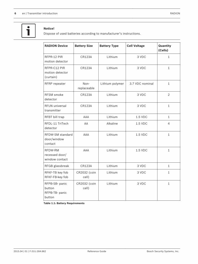
Notice!
Dispose of used batteries according to manufacturer’s instructions.
RADION Device Battery Size Battery Type Cell Voltage Quantity(Cells)
RFPR-12 PIRmotion detector
CR123A Lithium 3 VDC 1
RFPR-C12 PIRmotion detector(curtain)
CR123A Lithium 3 VDC 1
RFRP repeater Non-replaceable
Lithium polymer 3.7 VDC nominal 1
RFSM smokedetector
CR123A Lithium 3 VDC 2
RFUN universaltransmitter
CR123A Lithium 3 VDC 1
RFBT bill trap AAA Lithium 1.5 VDC 1
RFDL-11 TriTechdetector
AA Alkaline 1.5 VDC 4
RFDW-SM standarddoor/windowcontact
AAA Lithium 1.5 VDC 1
RFDW-RMrecessed door/window contact
AAA Lithium 1.5 VDC 1
RFGB glassbreak CR123A Lithium 3 VDC 1
RFKF-TB key fobRFKF-FB-key fob
CR2032 (coincell)
Lithium 3 VDC 1
RFPB-SB- panicbuttonRFPB-TB- panicbutton
CR2032 (coincell)
Lithium 3 VDC 1
Table 1.1: Battery Requirements
6 en | Transmitter introduction RADION
2015.04 | 01 | F.01U.304.662 Reference Guide Bosch Security Systems, Inc.

General installationPhases of installationThe installation of the RADION system is achieved by following the sequential process asdefined in this chapter. Overall, there are four main phases;– Planning– Physical installation of the devices– System enrollment/configuration– System testing (walk test, pattern test)It is essential that these steps or phases are adhered to in the order mentioned above forproper functionality and operation.When installing a RADION system, you must plan your installation based on the control paneland RADION device specifications, and the radio-frequency signal strength (RFSS) betweendevices, receivers, and control panels.
Installation considerations– RADION devices are intended only for indoor, dry applications.– Mount RADION devices on flat, rigid surfaces. Some devices can be optionally corner
mounted as indicated in the installation instructions.– Avoid mounting RADION devices in areas with large, metallic objects, electrical panels, or
electric motors. They might reduce the radio-frequency (RF) range of a RADION device.– Avoid installing the devices where excessive humidity, moisture, or temperatures outside
of the acceptable operating range exist.– Wire all objects according to their specifications.– RADION devices use batteries of varying types. When installing batteries, observe safety
and polarity recommendations as indicated in the documentation for those products.
Installation workflowTo install, configure, and test the system, use the workflow below and follow in sequentialorder, from top to bottom, checking each box as you complete a step.
Notice!
Always power down the control panel when connecting modules, or other wiring. Power
down the control panel by unplugging the transformer and disconnecting the battery
Plan the installation of the RADION system
Install the RADION components (refer to the graphical installation guides and this systemreference guide for details)
Program wireless points in the control panel
Enroll point RF ID for wireless points
Verify LED responses on devices
Perform a local walk test for installed detectors
Review signal strength and margin of each point
Complete the installation
2
2.1
RADION General installation | en 7
Bosch Security Systems, Inc. Reference Guide 2015.04 | 01 | F.01U.304.662

Unpacking informationWhen unpacking the receiver, repeater, or bill trap device, it is important to remove thecardboard insert as illustrated below;
Figure 2.1: Insert for the receiver and repeater
Figure 2.2: Insert for the bill trap
Wall tamper switch installationRADION transmitter devices contain a feature that activates the wall tamper switch located onthe base of the device. In order to properly install the device, you must consider the following:– To properly install a device with active wall tamper functionality, insert a screw in the
designated screw slot location.– Failure to insert a screw into the wall tamper slot prevents the wall tamper feature from
generating a tamper signal when the transmitter is pulled away from a wall.
Magnet cover installationDuring the installation of the plastic magnet cover, the cover is not designed to be separatedfrom the base after the base and cover are snapped together. Damage to the plastics mayoccur if separated.
Complete installationTesting the entire RADION system can only be achieved by performing an area wide testthrough the control panel and corresponding keypad(s). This is achieved by performing anoverall service walk test. Refer to your control panel documentation for system-walk, or othersystem-wide testing procedures.
2.2
2.3
2.4
2.5
8 en | General installation RADION
2015.04 | 01 | F.01U.304.662 Reference Guide Bosch Security Systems, Inc.

To ensure proper operation of the RADION devices, test the basic functionality of the devicelocally. Depending on the RADION device to be tested, perform the following procedures forfunctionality:– When testing the receiver, power up the compatible control panel in which the receiver is
connected to and observe the LED behavior on the receiver.– Local walk testing can be performed on the motion detectors as defined in the tritech
and PIR chapters of this guide.– Magnet testing can be performed by opening or closing the door/window in which the
magnet is installed on.
Maintenance
It is recommended to check the battery of each device annually. This will ensure properoperation and functionality of the devices.
Battery Life Extension feature (PIR and TriTech)In the normal operating mode, an alarm can be transmitted only after three (3) minutes havepassed since the previous alarm restoral. This 3 minute lockout time reduces unnecessary RFtransmissions in high traffic areas, thereby extending battery life.
2.6
RADION General installation | en 9
Bosch Security Systems, Inc. Reference Guide 2015.04 | 01 | F.01U.304.662

RADION repeaterThe RFRP is a combined receiver and transmission device that improves the overalltransmission, communication, and reliability capabilities of its assigned compatible receiver.An LED on the front provides device status.Features include:– LED Display– Cover and Wall Tamper protection
Notice!
The repeater is designed to improve the communication performance of the RADION wireless
portfolio, and not to extend the range of the wireless devices. Install the transmitters within
the suggested range for optimal performance and reliability.
Notice!
Use a supported transformer as defined in the specification table for the repeater. Do not
connect power supply to a receptacle controlled by a switch.
Installation considerationsUse the provided anchors and screws to mount the repeater in locations accessible for futuremaintenance. Mount the repeater onto a wall.
Notice!
Mount the repeater in a location removed from metal. Metal objects (duct work, wire mesh
screens, boxes) reduce RF range
Wiring considerations
Notice!
Do not install long cable runs next to high-current power feeds. Keep cable lengths as short
as possible to minimize noise pickup.
Ensure that the wiring used meets the following specifications:– Two-conductor unshielded wire.– The minimal requirement for wire length is 1.83 m (6 ft) from the repeater
3
3.1
3.2
10 en | RADION repeater RADION
2015.04 | 01 | F.01U.304.662 Reference Guide Bosch Security Systems, Inc.

Specifications
Dimensions 139.70 mm x 209.60 mm x 31.80 mm(5.50 in x 8.25 in x 1.25 in)
Power/Voltage(Standby battery)
16.5 VAC, 40VA (~)(EN voltage range: 16.5 VAC– 18 VAC) AC Type (device)Rated 3.7 VDC, 3050mAH EVE ENERGY CO Part No P0046-LF (Not userreplaceable). For standby battery to be operative, the tamper switch isrequired to be engaged.Power source type: ALow battery level: 3.5V
Transformer power/voltage Must meet country specific requirements
Current Draw 60 mA
Wire Gauge 0.65 mm (22 AWG) to 2.0 mm (18 AWG)
Temperature (operating) Functional range: -10゚C to +49゚(+14゚F to +120゚F)EN 50130-5 Class II only: -10゚C to 40゚C (+14゚F to +104゚F)
Relative Humidity 0% to 93% (non-condensing)
Device testing To ensure proper functionality, the device must be tested at least onceevery year by an installer.
Wall and Cover Tamper Switch Transmits a tamper signal when someone removes the device from itsbase or pulls it away from the wall.
Frequency 433.42 MHz
Table 3.1: Specifications
LEDsThe repeater utilizes an external LED indicator to status the operation of the repeater. Refer tothe table below for LED descriptions.
LED Condition Pattern Description
On (Normal) – Indicates the repeater is functioning normally.
Off – Indicates there is a power failure to the repeater, or that thereceiver is not wired correctly.
Continuous Flash: 1 secrate for 5 sec
– Indicates the repeater is being powered up, and conductionmanufacturing test initializations.
3.3
3.4
RADION RADION repeater | en 11
Bosch Security Systems, Inc. Reference Guide 2015.04 | 01 | F.01U.304.662

LED Condition Pattern Description
Continuous Flash: A 3-pulse signal, followed bya short delay after the 3rd
pulse
– Indicates the repeater has experienced a low batterycondition.
Continuous Flash: A 2flash pattern continuouspulse between On andOff states with a shortdelay after the 2nd pulse
– Indicates an AC power failure is detected.– A communication failure within internal hardware
components inside the receiver
12 en | RADION repeater RADION
2015.04 | 01 | F.01U.304.662 Reference Guide Bosch Security Systems, Inc.

RADION glassbreakThe RFGB is a wireless transmitter used for detecting breaking glass. Throughout thisdocument, the term “glassbreak” refers to glass break.Features include:– Monitored battery status
Dimension 101.42 mm x 112.90 mm x 35.00 mm(3.99 in x 4.44 in x 1.38 in)
Power/Voltage Battery/CR123A, 3 VDC ( )Power source type: CLow battery level: 2.15V
Battery replacement Duracell DL123A, Lithium, Panasonic CR123A Lithium, or SanyoCR123A Lithium. Check your battery yearly to ensure properfunctionality.
Battery life Up to 5 years
Device testing To ensure proper functionality, the device must be tested at leastonce every year.
Accoustic Capabilities Glass types andthickness
Type Thickness
Plate 2.4 mm to 6.4 mm(3/32 in to 1/4 in)
Tempered 3.2 mm to 6.4 mm(1/8 in to 1/4 in)
Laminated 3.2 mm to 6.4 mm(1/8 in to 1/4 in)
Wired 6.4 mm (1/4 in)
Minimum pane size for alltypes of glass
1.2 m (4 ft)
Microphone Omni-directional 360゚ electret
OperatingTemperature
Functional range: -10°C to +49°C (+14°F to +120°F)EN 50130-5 Class II only: -10゚C to 40゚C (+14゚F to +104゚F)
Relative Humidity 0% to 93% (non-condensing)
Wall and CoverTamper Switch
Transmits a tamper signal when someone removes the device fromits base or pulls it away from the wall.
Frequency 433.42 MHz
Table 4.1: Specifications
Installation considerationsFor the best detector performance, select a mounting location that is:– Mounted on the ceiling within a maximum range of 20 ft (6 m)
4
4.1
RADION RADION glassbreak | en 13
Bosch Security Systems, Inc. Reference Guide 2015.04 | 01 | F.01U.304.662

– For armor-coated glass installations, mount the sensor no more than 12 ft (3.65 m) fromthe glass
– Mount the detector in the direct line of sight of the glass to be protected– On an opposite, or adjoining wall, within a range of 20 ft (6 m) for plate, tempered,
laminated, and wired glass– In a suitable environment: temperature between -18 and 50゚C (0 and 120゚F); and
humidity between 10 and 90% non-condensingAvoid mounting the detector in:– Glass airlocks and glass vestibule areas– Humid rooms– Small utility rooms– Rooms with noisy equipment (white noise) such as air compressors, bells, and power
tools– Rooms smaller than 10 ft x 10 ft (3 m x 3 m)– Rooms with lined, insulating, or sound supressing drapes– A corner of a roomAvoid locations that expose the detector to possible false-alarm sources such as:– Glass airlocks and vestibule areas;– Kitchens;– Corner mounting;– Residential car garages;– Stairwells– Bathrooms; and– Small acoustically live rooms
Notice!
Glassbreak detectors are intended only as a component of a perimeter protection system.
Use glassbreak detectors in conjunction with motion detectors.
TestingTest the detector at least once yearly. Use the Sentrol 5709C hand-held tester to enter thesensor into test mode and to test the alarm.
Test the sensor alarmTo test the sensor functionality, enter the detector into test mode. In normal mode, the sensordoes not generate an alarm on sound signals from the tester unless the tester is held next tothe sensor.Each time the sensor alarms, it also goes into test mode for one minute.Initiating test mode with the Sentrol 5709C hand-held tester:1. Set the tester for tempered or laminated glass, unless the protected glass is plate glass.2. Hold the tester on top of the detector.3. Activate the tester. The detector alarms and goes into test mode for one minute. During
test mode, the LED blinks continuously. To extend test time, activate the tester within therange of the sensor at least once each minute.
Performing the alarm test with Sentrol 5709C hand-held tester:1. Hold the tester near the surface of the glass to be protected and aim the speaker at the
sensor. Be sure the tester is at the point on the glass farthest from the detector.
4.2
14 en | RADION glassbreak RADION
2015.04 | 01 | F.01U.304.662 Reference Guide Bosch Security Systems, Inc.

Notice!
If blinds or drapes are present, test the area by holding the hand-held tester behind the
closed blinds or drapes.
2. Press the test button on the tester. The LED on the detector stays on for 4 seconds toindicate the glass is within detection range of the sensor. If the LED does not stay in asolid state momentarily, but continues to blink, adjust the positioning of the detector sothat it is closer to the window, and re-test. Check the battery strength of the hand-heldtesting device before the test.
Figure 4.1: Testing behind curtains
The detector switches from test mode to normal mode after at least 1 minute of silence fromthe hand-held tester.
Notice!
When the detector is in normal mode, the LED is off unless a loud sound is detected.
Room acoustics can artificially extend the range of a glassbreak sensor. The specified sensorrange is for worst-case conditions. While the sensor likely functions at a greater range, it mightnot detect a low volume breaking sound, or room acoustics might change at a later point intime. Do not exceed the rated range of the sensor, regardless of what the tester shows.
Test the sensor operabilityWhen the detector is in normal mode, the LED is off unless a loud sound is detected.Therefore, to ensure the glassbreak has power and that the microphone is functional, performa simple hand clap test.To perform a hand clap test, simply clap your hard loudly under the sensor. Verify the LEDblinks twice.
RADION RADION glassbreak | en 15
Bosch Security Systems, Inc. Reference Guide 2015.04 | 01 | F.01U.304.662
Low batteryWhen a low battery state is detected, the detector measures the battery, and sends a reportto the receiver/control panel.
Wall Tamper TabUse the wall tamper tab to activate an alarm when the glass break has been removed from thewall.
MaintenanceClean the cover with a damp (water) cloth as needed to keep it free of dust and dirt. Alwaystest the sensor after cleaning it.
4.3
4.4
4.5
16 en | RADION glassbreak RADION
2015.04 | 01 | F.01U.304.662 Reference Guide Bosch Security Systems, Inc.

RADION TriTechThe RFDL-11 is a motion detector which uses artificial intelligence to detect motion andprovide immunity to false alarms. An integral RF transmitter reports low battery and tamperstatus, and sends a supervisory signal to the control panel. Features include:– 11m x 11m (35 ft by 35 ft) coverage– Flexible mounting height– Compatible with Bosch RADION wireless systems– Draft and Insect immune– Cover activated tamper indication. Optional wall-activated tamper is included
Dimension 138.00 mm x 72.00 mm x 64.00 mm(5.43 in x 2.83 in x 2.52 in)
Relative humidity 0% to 93%, (non-condensing)
Temperature (operating) Functional range: -10°C to +49°C (+14°F to +120°F)EN 50130-5 Class II only: -10゚C to 40゚C (+14゚F to+104゚F)
Internal coverage directionality Vertical: -4゚ to -10゚
Sensitivity selection Field selectable for standard or intermediate sensitivity
Power/voltage Four AA Alkaline batteries, 1.5 VDC ( ). 1.5 VDCx 4 = 6 VDC total.Power source type: CLow battery level: 3.6V
Battery replacement Duracell MN1500, Panasonic AM-3PIX. Check yourbattery yearly to ensure proper functionality.
Battery life Up to 5 years
Device testing To ensure proper functionality, the device must betested at least once every year by an installer.
Wall and cover tamper switch Transmits a tamper signal when someone removes thedevice from its base or pulls it away from the wall.
Frequency 433.42 MHz
Table 5.1: Specifications
Mounting height and range adjustmentLoosen the vertical adjustment screw. Adjust the board to the desired angle. Choose mountingheight and desired range, and set the vertical angle. Reference the table below for properheight and adjustment values.
Mounting height Range
6.1 m (20 ft) 10.7 m (35 ft)
2 m (6.5 ft) -7゚ -5゚
5
5.1
RADION RADION TriTech | en 17
Bosch Security Systems, Inc. Reference Guide 2015.04 | 01 | F.01U.304.662
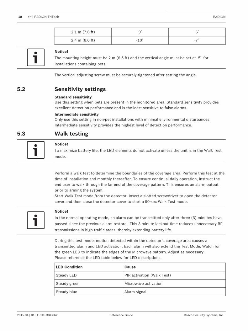
2.1 m (7.0 ft) -9゚ -6゚
2.4 m (8.0 ft) -10゚ -7゚
Notice!
The mounting height must be 2 m (6.5 ft) and the vertical angle must be set at -5゚ for
installations containing pets.
The vertical adjusting screw must be securely tightened after setting the angle.
Sensitivity settingsStandard sensitivityUse this setting when pets are present in the monitored area. Standard sensitivity providesexcellent detection performance and is the least sensitive to false alarms.
Intermediate sensitivityOnly use this setting in non-pet installations with minimal environmental disturbances.Intermediate sensitivity provides the highest level of detection performance.
Walk testing
Notice!
To maximize battery life, the LED elements do not activate unless the unit is in the Walk Test
mode.
Perform a walk test to determine the boundaries of the coverage area. Perform this test at thetime of installation and monthly thereafter. To ensure continual daily operation, instruct theend user to walk through the far end of the coverage pattern. This ensures an alarm outputprior to arming the system.Start Walk Test mode from the detector. Insert a slotted screwdriver to open the detectorcover and then close the detector cover to start a 90-sec Walk Test mode.
Notice!
In the normal operating mode, an alarm can be transmitted only after three (3) minutes have
passed since the previous alarm restoral. This 3 minute lockout time reduces unnecessary RF
transmissions in high traffic areas, thereby extending battery life.
During this test mode, motion detected within the detector’s coverage area causes atransmitted alarm and LED activation. Each alarm will also extend the Test Mode. Watch forthe green LED to indicate the edges of the Microwave pattern. Adjust as necessary.Please reference the LED table below for LED descriptions.
LED Condition Cause
Steady LED PIR activation (Walk Test)
Steady green Microwave activation
Steady blue Alarm signal
5.2
5.3
18 en | RADION TriTech RADION
2015.04 | 01 | F.01U.304.662 Reference Guide Bosch Security Systems, Inc.
LED Condition Cause
Flashing blue Warm-up period after power-up
No LED upon initial power up PIR failure. Replace unit.
Walking Testing the system1. Start at the pattern’s expected boundary and walk across the pattern moving closer to
the detector. Set the adjustment as low as possible for proper catch performance.
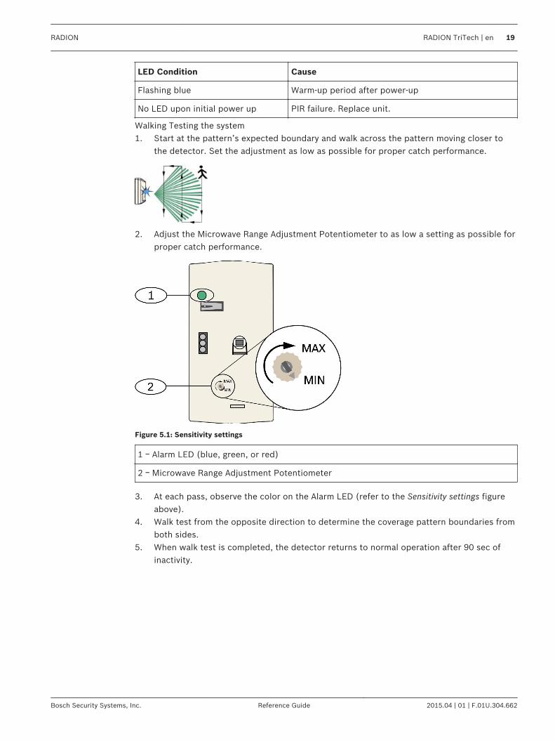
2. Adjust the Microwave Range Adjustment Potentiometer to as low a setting as possible forproper catch performance.
Figure 5.1: Sensitivity settings
1 ᅳ Alarm LED (blue, green, or red)
2 ᅳ Microwave Range Adjustment Potentiometer
3. At each pass, observe the color on the Alarm LED (refer to the Sensitivity settings figureabove).
4. Walk test from the opposite direction to determine the coverage pattern boundaries fromboth sides.
5. When walk test is completed, the detector returns to normal operation after 90 sec ofinactivity.
RADION RADION TriTech | en 19
Bosch Security Systems, Inc. Reference Guide 2015.04 | 01 | F.01U.304.662

RADION PIRThe RFPR-12 is a high performance PIR motion detector that uses advanced signal processing.An integrated wireless transmitter sends a battery report with each transmission, andtransmits a supervisory signal to the control panel. Features include:– 12 m x 12 m (40 ft x 40 ft) coverage– Flexible Mounting Height
Dimensions 111.00 mm x 60.00 mm x 43.00 mm(4.40 in x 2.40 in x 1.70 in)
Relative humidity 0% to 93%, non-condensing
Temperature (operating) Functional range: -10°C to +49°C (+14°F to +120°F)EN 50130-5 Class II only: -10゚C to 40゚C (+14゚F to+104゚F)
Power/voltage One CR123A Lithium battery, 3 VDC ( )Power source type: CLow battery level: 2,15V
Battery replacement Duracell DL123A , Panasonic CR123A, or SanyoCR123A. Check your battery yearly to ensure properfunctionality.
Battery life Up to 5 years
Device testing To ensure proper functionality, the device must betested at least once every year by an installer.
Wall and cover tamper switch Transmits a tamper signal when someone removes thedevice from its base or pulls it away from the wall.
Frequency 433.42 MHz
Table 6.1: Specifications
Walk testingPerform a walk test to determine the boundaries of the coverage area.Insert a slotted screwdriver into the designated hole to open the cover and then close thedetector cover to start a 90-sec Walk Test mode.During this test mode, motion detected within the detector’s coverage area causes atransmitted alarm and LED activation. Each alarm will also extend the Test Mode. Adjust asnecessary.
Notice!
Excessive use of the Walk Test Mode may reduce battery life. Use only for initial setup and
maintenance testing.
6
6.1
20 en | RADION PIR RADION
2015.04 | 01 | F.01U.304.662 Reference Guide Bosch Security Systems, Inc.
Notice!
In the normal operating mode, an alarm can be transmitted only after three (3) minutes have
passed since the previous alarm restoral. This 3 minute lockout time reduces unnecessary RF
transmissions in high traffic areas, thereby extending battery life.
Refer to the LED table below for LED descriptions.
LED condition Cause
Steady blue PIR activation (Walk Test)
Flashing blue Warm-up period after power-up
Flashing blue (four-pulse sequence) PIR failure. Replace unit.
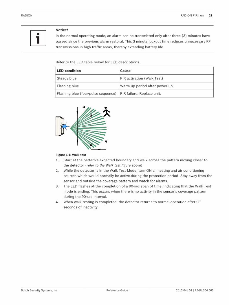
Figure 6.1: Walk test
1. Start at the pattern’s expected boundary and walk across the pattern moving closer tothe detector (refer to the Walk test figure above).
2. While the detector is in the Walk Test Mode, turn ON all heating and air conditioningsources which would normally be active during the protection period. Stay away from thesensor and outside the coverage pattern and watch for alarms.
3. The LED flashes at the completion of a 90-sec span of time, indicating that the Walk Testmode is ending. This occurs when there is no activity in the sensor’s coverage patternduring the 90-sec interval.
4. When walk testing is completed. the detector returns to normal operation after 90seconds of inactivity.
RADION RADION PIR | en 21
Bosch Security Systems, Inc. Reference Guide 2015.04 | 01 | F.01U.304.662

RADION PIR CThe RFPR-C12 is a high performance curtain PIR motion detector that uses advanced signalprocessing to provide outstanding catch performance and unsurpassed false alarm immunity.The detector contains an integrated RF transmitter. The transmitter sends a battery reportwith each transmission, and transmits a supervisory signal to the control panel. Featuresinclude:– 12 m x 1.5 m (40 ft x 5 ft) curtain coverage– Flexible Mounting Height
Dimensions 111.00 mm x 60.00 mm x 43.00 mm(4.40 in x 2.40 in x 1.70 in)
Relative humidity 0% to 93%, non-condensing
Temperature (operating) Functional range: -10°C to +49°C (+14°F to +120°F)EN 50130-5 Class II only: -10゚C to 40゚C (+14゚F to +104゚F)
Power/voltage One CR123A Lithium batteries, 3 VDC ( )Power source type: CLow battery level: 2,15V
Battery replacement Duracell DL123A, Panasonic CR123A, or Sanyo CR123A.Check your battery yearly to ensure proper functionality.
Battery life Up to 5 years
Device testing To ensure proper functionality, the device must be testedat least once every year by an installer.
Wall and cover tamper switch Transmits a tamper signal when someone removes thedevice from its base or pulls it away from the wall.
Frequency 433.42 MHz
Table 7.1: Specifications
Walk testingPerform a walk test to determine the boundaries of the coverage area.Insert a slotted screwdriver into the designated hole to open the cover and then close thedetector cover to start a 90-sec Walk Test mode.During this test mode, motion detected within the detector’s coverage area causes atransmitted alarm and LED activation. Each alarm will also extend the Test Mode. Adjust asnecessary.
Notice!
Excessive use of the Walk Test Mode may reduce battery life. Use only for initial setup and
maintenance testing.
7
7.1
22 en | RADION PIR C RADION
2015.04 | 01 | F.01U.304.662 Reference Guide Bosch Security Systems, Inc.

Notice!
In the normal operating mode, an alarm can be transmitted only after three (3) minutes have
passed since the previous alarm restoral. This 3 minute lockout time reduces unnecessary RF
transmissions in high traffic areas, thereby extending battery life.
Refer to the LED table below for LED descriptions.
LED condition Cause
Steady blue PIR activation (Walk Test)
Flashing blue Warm-up period after power-up
Flashing blue (four-pulse sequence) PIR failure. Replace unit.
Figure 7.1: Walk test
1. Start at the pattern’s expected boundary and walk across the pattern moving closer tothe detector (refer to the Walk test figure above).
2. While the detector is in the Walk Test Mode, turn ON all heating and air conditioningsources which would normally be active during the protection period. Stay away from thesensor and outside the coverage pattern and watch for alarms.
3. The LED flashes at the completion of a 90-sec span of time, indicating that the Walk Testmode is ending. This occurs when there is no activity in the sensor’s coverage patternduring the 90-sec interval.
4. When walk testing is completed. the detector returns to normal operation after 90seconds of inactivity.
RADION RADION PIR C | en 23
Bosch Security Systems, Inc. Reference Guide 2015.04 | 01 | F.01U.304.662

RADION smokeThe RFSM is a non-latching wireless smoke detector that sends an alarm signal to the receiver.The following features include:– A visual status LED– A built-in sounder for alarm alerts– Under normal conditions, the red LED flashes once every 8 sec while the sensor monitors
the surrounding environment. When the sensor detects smoke, the LED changes fromflashing to steady ON and the sounder produces a loud, continuous tone. Refer to theLED table for more information.
Replaceable optical chamber For easy maintenance
Power/voltage Two CR123A Lithium batteries, 3 VDC ( )Power source type: CLow battery level: 2.15V
Current draw Standby: 45 uAAlarm: 70 mA
Battery replacement Duracell DL123A, Panasonic CR123A, or Sanyo CR123A.Check your batteries yearly to ensure properfunctionality.
Battery life Minimum of 5 years or greater
Device testing To ensure proper functionality, the device must be testedat least once every year.
Sensitivity 0.14+/- 0.04 bM/m (0.97 – 2.99%/ft obscuration – RFSM-A only)
Temperature (operating) Functional range: -10゚C to +49゚(+14゚F to +120゚F)EN 50130-5 Class II only: -10゚C to 40゚C (+14゚F to +104゚F)
Relative humidity 0% to 93% (non-condensing)
Cover and wall tamper switch Transmits a tamper switch signal when the detector isremoved from its base, or the unit is pulled away fromthe wall.
Drift compensation adjustment -1.64%/m (0.5%/ft) maximum
Sounder 85 dBA at 3 m
Self-diagnostics feature Monitors detector sensitivity and operational status.
Frequency 433.42 MHz
Table 8.1: Specifications
8
24 en | RADION smoke RADION
2015.04 | 01 | F.01U.304.662 Reference Guide Bosch Security Systems, Inc.
12
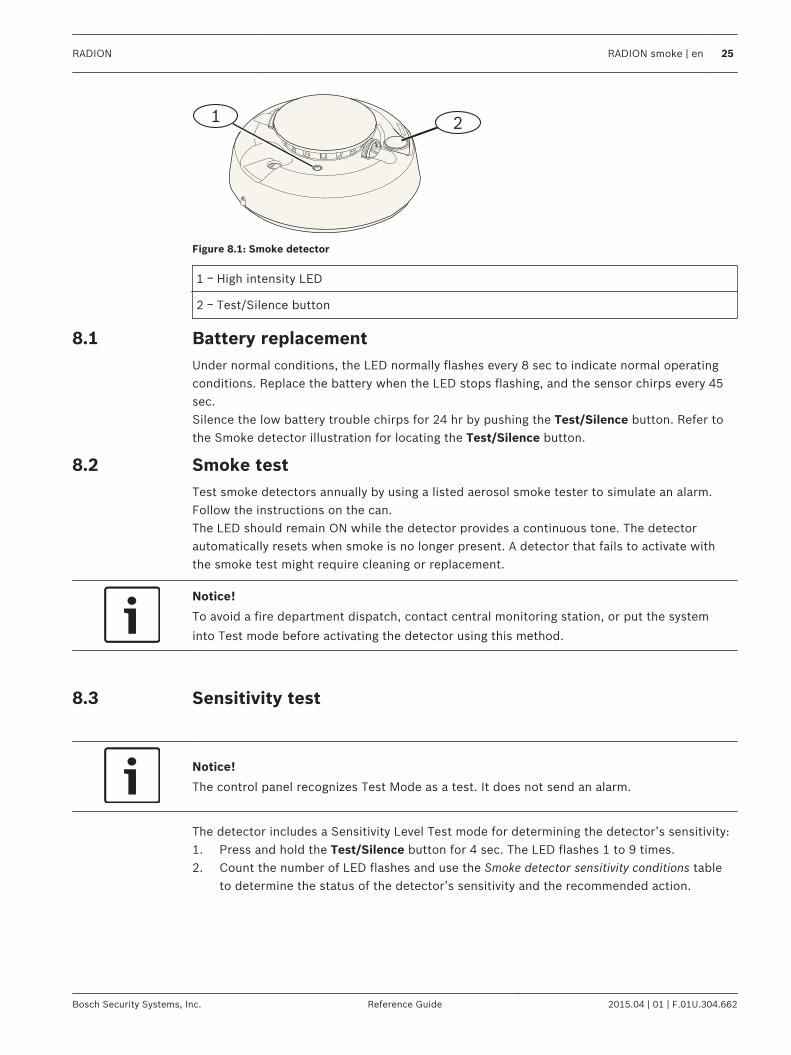
Figure 8.1: Smoke detector
1 ᅳ High intensity LED
2 ᅳ Test/Silence button
Battery replacementUnder normal conditions, the LED normally flashes every 8 sec to indicate normal operatingconditions. Replace the battery when the LED stops flashing, and the sensor chirps every 45sec.Silence the low battery trouble chirps for 24 hr by pushing the Test/Silence button. Refer tothe Smoke detector illustration for locating the Test/Silence button.
Smoke testTest smoke detectors annually by using a listed aerosol smoke tester to simulate an alarm.Follow the instructions on the can.The LED should remain ON while the detector provides a continuous tone. The detectorautomatically resets when smoke is no longer present. A detector that fails to activate withthe smoke test might require cleaning or replacement.
Notice!
To avoid a fire department dispatch, contact central monitoring station, or put the system
into Test mode before activating the detector using this method.
Sensitivity test
Notice!
The control panel recognizes Test Mode as a test. It does not send an alarm.
The detector includes a Sensitivity Level Test mode for determining the detector’s sensitivity:1. Press and hold the Test/Silence button for 4 sec. The LED flashes 1 to 9 times.2. Count the number of LED flashes and use the Smoke detector sensitivity conditions table
to determine the status of the detector’s sensitivity and the recommended action.
8.1
8.2
8.3
RADION RADION smoke | en 25
Bosch Security Systems, Inc. Reference Guide 2015.04 | 01 | F.01U.304.662
Flashes Action Recommended
1 Self-diagnostics failure. Return detector for service orreplacement.
2 to 3 Detector is becoming insensitive. Clean detector and re-test. Iferror persists, replace the detector.
4 to 7 Detector is within normal sensitivity settings.
8 to 9 Detector is becoming too sensitive. Confirm that the smokechamber is snapped down securely. Clean the sensor and re-test.
Table 8.2: Smoke detector sensitivity conditions
Test/Silence buttonRefer to the RADION smoke detector illustration for location of the Test/Silence button.– Testing. Press the Test/Silence button for 4 sec. The detector performs a Sounder test
and a Sensitivity test.– Silence alarm. Press to silence the sounder during an alarm. After a few minutes, the
sounder and alarm resume if smoke is still present.
Remote monitoring station alarm testPress the button for fifteen (or 20) seconds to send a fire alarm signal to the remotemonitoring station.
Notice!
To avoid a fire department dispatch, contact the remote monitoring station or put the control
panel into the corresponding test mode before performing this test.
LED
LED Status
Flashing Flashes every 8 sec under normal operation.
ON Detects smoke, sending an alarm.
OFF Malfunction, replace the batteries, clean the detector, or replacethe optical chamber as required.
Table 8.3: LED
Clean the detector and replace the optical chamberClean the detector cover with a dry or damp cloth as needed to keep it free from dust anddirt. Clean the detector interior at least yearly.Cleaning the detector:1. Remove the detector from the mounting base.2. Remove the batteries.3. Slide a slotted screwdriver into the slot on the detector cap and gently push down to pry
off the cap.
8.4
8.5
8.6
26 en | RADION smoke RADION
2015.04 | 01 | F.01U.304.662 Reference Guide Bosch Security Systems, Inc.
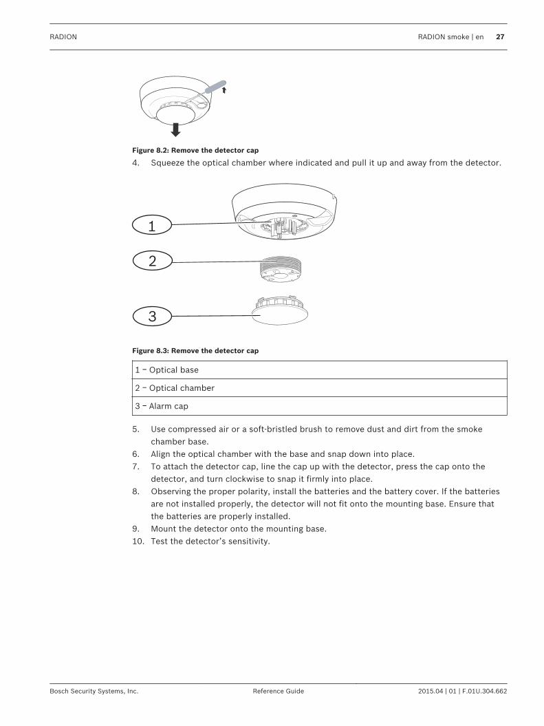
Figure 8.2: Remove the detector cap
4. Squeeze the optical chamber where indicated and pull it up and away from the detector.
1
2
3
Figure 8.3: Remove the detector cap
1 ᅳ Optical base
2 ᅳ Optical chamber
3 ᅳ Alarm cap
5. Use compressed air or a soft-bristled brush to remove dust and dirt from the smokechamber base.
6. Align the optical chamber with the base and snap down into place.7. To attach the detector cap, line the cap up with the detector, press the cap onto the
detector, and turn clockwise to snap it firmly into place.8. Observing the proper polarity, install the batteries and the battery cover. If the batteries
are not installed properly, the detector will not fit onto the mounting base. Ensure thatthe batteries are properly installed.
9. Mount the detector onto the mounting base.10. Test the detector’s sensitivity.
RADION RADION smoke | en 27
Bosch Security Systems, Inc. Reference Guide 2015.04 | 01 | F.01U.304.662

RADION contact SMThe RFDW-SM is a standard surface-mount wireless transmitter device used for monitoringdoors and windows.Features include:– An internal reed switch– A cover and wall tamper switch
Power/voltage One AAA Lithium battery, 1.5 VDC ( )Power source type: CLow battery level: 0.9V
Battery replacement Energizer L92. Check your battery yearly to ensureproper functionality.
Battery life Up to 5 years
Device testing To ensure proper functionality, the device must be testedat least once every year by an installer.
Dimensions (transmitter) 19.50 mm x 82.55 mm x 12.80 mm(0.76 in x 3.25 in x 0.50 in)
Dimensions (magnet) 24.5 mm x 18.5 mm x 12.5 mm(0.97 in x 0.72 in x 0.49 in)
Temperature (operating) Functional range: -10°C to +49°C (+14°F to +120°F)EN 50130-5 Class II only: -10゚C to 40゚C (+14゚F to +104゚F)
Relative humidity 0% to 93% (non-condensing)
Wall and Cover Tamper Switch Transmits a tamper signal when someone removes thedevice from its base or pulls it away from the wall.
Frequency 433.42 MHz
Table 9.1: Specifications
Installation considerationsYou have a variety of installation options to consider when installing the device. You mustacknowledge the unique installation approach prior to installation. Some installationconsiderations include:– Suitable surfaces for installation include wood, steel, and aluminum.– The location of the magnet and transmitter in relationship to the door/window frame
dimensions. Verify you have proper clearance with the latch of the window or door youare installing the device onto. Failure to do so will make it extremely difficult to accessand open the device for maintenance purposes.
– In some cases, you might need an additional spacer when installing the transmitter andmagnet in the corner of a recessed door or window frame to close the gap in heightbetween the magnet and transmitter.
– For additional security, you can use an adhesive with the screws to secure thetransmitters and magnets during installation.
9
9.1
28 en | RADION contact SM RADION
2015.04 | 01 | F.01U.304.662 Reference Guide Bosch Security Systems, Inc.
– When installing the magnet, verify that the notches in the magnet base, line up with thenotches in the transmitter base, otherwise the magnet and transmitter do not functioneffectively.
– When installing the magnet base, install the face of the magnet base flush to the surfaceedge of the installation location. This prevents damage to the magnet plastic basewhenever a window or door is opened.
– Adhere to the distances prescribed in the graphical table found in the graphicalInstallation and Operation Guide when installing the magnet adjacent to the transmitter.
How to read the Graphical Magnet Distances tableContained in the RADION contact SM Installation Guide is a graphical table along with the X ᅳ Yᅳ Z coordinates graphic. Use the table in conjunction with the graphic to determine desireddistances between the magnet and the transmitter based on the type of installation (wood ormetal).
Notice!
The content in the Installation Guide table applies to EN installations.
RADION RADION contact SM | en 29
Bosch Security Systems, Inc. Reference Guide 2015.04 | 01 | F.01U.304.662

RADION contact RMThe RFDW-RM is a recessed-mounted wireless transmitter device used for monitoring doorsand windows. Features include:– Self-contained transmitter with magnetic reed switch– Tamper protection– Recessed mounting on doors or windows
Power/voltage One AAA Lithium battery, 1.5 VDC ( )Power source type: CLow battery level: 0.9V
Battery replacement Energizer L92. Check your battery yearly to ensure properfunctionality.
Battery life Up to 5 years
Device testing To ensure proper functionality, the device must be tested atleast once every year by an installer.
Dimensions (transmitter) 19.00 mm x 104.80 mm(0.75 in x 4.12 in)
Dimensions (magnet) 22 mm x 28 mm x 15 mm(0.87 in x 1.10 in x 0.59 in)
Relative humidity 0% to 93%, non-condensing
Temperature (operating) Functional range: -10°C to +49°C (+14°F to +120°F)EN 50130-5 Class II only: -10゚C to 40゚C (+14゚F to +104゚F)
Frequency 433.42 MHz
Table 10.1: Specifications
Installation considerationsYou have a variety of installation options to consider when installing the device. You mustacknowledge the unique installation approach prior to installation. Some installationconsiderations include:– The installation of this device is suitable for wood surfaces. This device is not suitable for
steel surfaces.– The transmitter housing was designed to be open with a coin. Using a screwdriver may
cause damage to the plastic top.– When reinserting the PCB (battery and antenna assembly), verify that the PCB assembly
fits into the grooves of the transmitter housing.– When reinserting the plastic top, verify that the top fits into the designed grooves of the
transmitter housing.– When installing the transmitter in an overhead location, be mindful that the PCB
assembly may fall out of the transmitter housing.– The removal of the plastic flaps is optional, depending on your installation needs.– For added security, you can use an adhesive with the screws to secure the transmitters
and magnets.
10
10.1
30 en | RADION contact RM RADION
2015.04 | 01 | F.01U.304.662 Reference Guide Bosch Security Systems, Inc.

Notice!
EN requirements
For further information regarding certified installations, please refer to EN product
requirements.
How to read the Graphical Magnet Distances tableContained in the recessed door/window contact Installation Guide is a graphical table alongwith the X ᅳ Y coordinates graphic. Use the table in conjunction with the graphic to determinedesired distances between the magnet and the transmitter based on the type of installation.
RADION RADION contact RM | en 31
Bosch Security Systems, Inc. Reference Guide 2015.04 | 01 | F.01U.304.662
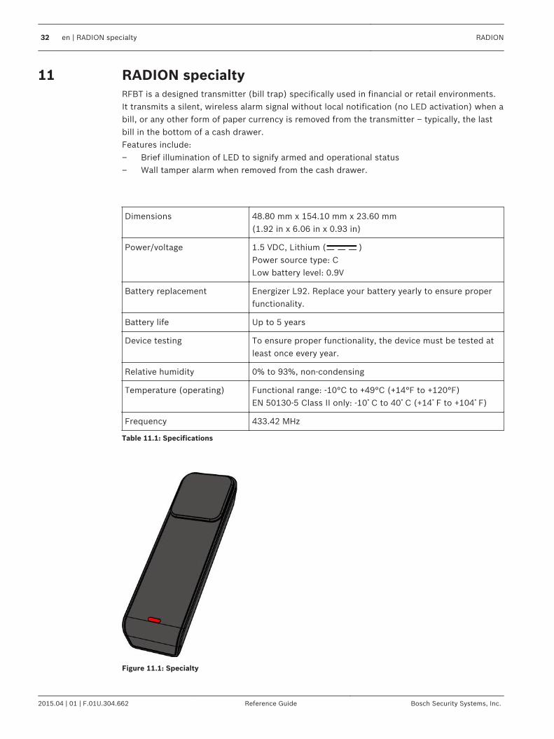
RADION specialtyRFBT is a designed transmitter (bill trap) specifically used in financial or retail environments.It transmits a silent, wireless alarm signal without local notification (no LED activation) when abill, or any other form of paper currency is removed from the transmitter – typically, the lastbill in the bottom of a cash drawer.Features include:– Brief illumination of LED to signify armed and operational status– Wall tamper alarm when removed from the cash drawer.
Dimensions 48.80 mm x 154.10 mm x 23.60 mm(1.92 in x 6.06 in x 0.93 in)
Power/voltage 1.5 VDC, Lithium ( )Power source type: CLow battery level: 0.9V
Battery replacement Energizer L92. Replace your battery yearly to ensure properfunctionality.
Battery life Up to 5 years
Device testing To ensure proper functionality, the device must be tested atleast once every year.
Relative humidity 0% to 93%, non-condensing
Temperature (operating) Functional range: -10°C to +49°C (+14°F to +120°F)EN 50130-5 Class II only: -10゚C to 40゚C (+14゚F to +104゚F)
Frequency 433.42 MHz
Table 11.1: Specifications
Figure 11.1: Specialty
11
32 en | RADION specialty RADION
2015.04 | 01 | F.01U.304.662 Reference Guide Bosch Security Systems, Inc.

Applications for this productUsage of this product is to provide concealed protection against theft in a financial institutionsuch as a bank, or in other commercial environments such as retail businesses and shops. Insome cases, the cash drawer is removed from the teller or cashier station, and stored inside abank vault at the close of each business day. In this scenario, the bank vault system is alwaysarmed, and the bill trap remains in a non-faulted condition. It is recommended to use the 3Mdouble sided tape when inserting into the cash drawer.In other occasions, the bill trap itself may be removed from the cash drawer at the end of aworkers shift. In this situation, the bill trap unit will generate a tamper condition uponremoval. In this type of application, it is important that the system must be configured suchthat the tamper does not generate a silent alarm. For this occasion, the hook and loop may bea more suitable mounting technique.
Installation considerationDuring the installation process, use the self-adhesive Velcro strips located on the bottom ofthe bill trap base, to secure and stabilize the bill trap in the cash drawer. This is achieved byperforming the following:1. Separate the Velcro strips from one another.2. Peel off the protective backing of the Velcro strips.3. Press the two bottom sections of the Velcro onto the bottom of the cash drawer, in the
desired location.4. Line up and press down on the bill trap so that the Velcro on the bottom of the bill trap is
aligned with the Velcro strips inside the cash drawer.
!Warning!
It is important to check the Velcro strips on a weekly basis for wear and replace when
appropriate in order to prevent potential false alarms.
11.1
11.2
RADION RADION specialty | en 33
Bosch Security Systems, Inc. Reference Guide 2015.04 | 01 | F.01U.304.662
RADION universal transmitterThe RFUN is a wireless transmitter used for monitoring doors, windows, and other dry contactdevices.Features include:– A cover and wall tamper switch– Single input with magnetic contact– Ability to connect to an external detector
Wire gauge 0.65 mm (22 AWG) to 1.5 mm (16 AWG)
Wiring distance Maximum distance of 7.62 m (25 ft)
Power/voltage Lithium battery, 3 VDC (Power source type: CLow battery level: 2.15V)
Battery replacement One Duracell DL123A, or Panasonic CR123A, or SanyoCR123A. Check your battery yearly to ensure properfunctionality.
Battery life Up to 5 years
Device testing To ensure proper functionality, the device must be testedat least once every year by an installer.
Temperature (operating) Functional range: -10゚C to +49゚(+14゚F to +120゚F)EN 50130-5 Class II only: -10゚C to 40゚C (+14゚F to +104゚F)
Relative Humidity 0% to 93% (non-condensing)
Terminal block For connecting other dry contact devices such as anothermagnetic reed switch.
Wall and cover tamper switch Transmits a tamper signal when someone removes thedevice from its base or pulls it away from the wall.
Frequency 433.42 MHz
Table 12.1: Specifications
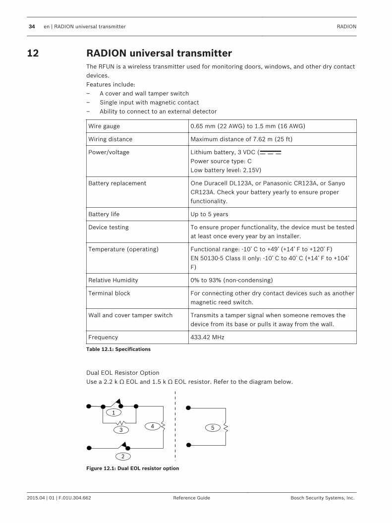
Dual EOL Resistor OptionUse a 2.2 k Ω EOL and 1.5 k Ω EOL resistor. Refer to the diagram below.
1
34
2
5
Figure 12.1: Dual EOL resistor option
12
34 en | RADION universal transmitter RADION
2015.04 | 01 | F.01U.304.662 Reference Guide Bosch Security Systems, Inc.

1 ᅳ Normally-closed (NC) alarm
2 ᅳ Normally-closed (NC) tamper
3 ᅳ 1.5 k Ω alarm EOL
4 ᅳ 2.2 k Ω tamper EOL
5 ᅳ Input disabled – no contact, 2.2 k Ω EOL
Installation considerationsYou have a variety of installation options to consider when installing the device. You mustacknowledge the unique installation approach prior to installation. Some installationconsiderations include:– The location of the magnet and transmitter in relationship to the door/window frame
dimensions. Verify you have proper clearance with the latch of the window or door youare installing the device onto. Failure to do so will make it extremely difficult to accessand open the device for maintenance purposes.
– In some cases, you might need an additional spacer when installing the transmitter andmagnet in the corner of a recessed door or window frame to close the gap in heightbetween the magnet and transmitter.
– On surface areas that are not conducive to mounting via the screws, you can securetransmitters and magnets using an industrial strength adhesive.
– When installing the magnet, verify that the notches in the magnet base, line up with thenotches in the transmitter base, otherwise the magnet and transmitter do not functioneffectively.
– When installing the magnet base, install the face of the magnet base flush to the surfaceedge of the installation location. This prevents damage to the magnet plastic basewhenever a window or door is opened.
– Adhere to the distances prescribed in the graphical table found in the graphicalInstallation and Operation Guide when installing the magnet adjacent to the transmitter.
How to read the Graphical Magnet Distances tableContained in the universal transmitter Installation and Operation Guide is a graphical tablealong with the X ᅳ Y ᅳ Z coordinates graphic. Use the table in conjunction with the graphic todetermine desired distances between the magnet and the transmitter based on the type ofinstallation (wood or metal).
Notice!
The content in the graphical table applies to EN installations.
Reed switch settingsSet the detector to enable or disable the reed switch.
Notice!
Please note, insert the jumper onto the pin prior to installing the battery. Failure to do so may
result in unexpected operation of the device.
12.1
12.2
RADION RADION universal transmitter | en 35
Bosch Security Systems, Inc. Reference Guide 2015.04 | 01 | F.01U.304.662

Callout ᅳ Description
1 ᅳ No jumper disables the internal reed switch
2 ᅳ Jumper on enables the internal reed switch
36 en | RADION universal transmitter RADION
2015.04 | 01 | F.01U.304.662 Reference Guide Bosch Security Systems, Inc.

RADION keyfobRADION keyfobs (two button and four button) are personal transmitters carried by the userthat allow the user to remotely arm or disarm a security area.
Dimensions 63.70 mm x 35.50 mm x 13.00 mm(2.51 in x 1.40 in x 0.51 in)
Power/voltage One Lithium battery (CR2032)3 VDCPower source type: CLow battery level: 2.1V
Battery replacement Panasonic CR2032, Duracell DL2032. Checkyour Battery yearly to ensure properfunctionality
Battery life Up to 5 years
Temperature (operating) Functional range: -10°C to +49°C (+14°F to+120°F)EN 50130-5 Class II only: -10゚C to 40゚C (+14゚F to +104゚F)
Relative humidity 0% to 93% (non-condensing)
Frequency 433.42 MHz
Table 13.1: Specifications
Notice!
Please note, the battery does not come installed. Refer to the specification table for the
correct battery type when replacing an old battery.
Keyfob buttonsRefer to your control panel’s documentation to program the functions of the programmablebuttons.Pressing either the arm or disarm button causes the LED to flash for about 2 sec., indicatingthe keyfob sent commands to the control panel.
Notice!
Pressing the Arm and Disarm buttons in unison for 1 sec transmits a panic alarm.
13
RADION RADION keyfob | en 37
Bosch Security Systems, Inc. Reference Guide 2015.04 | 01 | F.01U.304.662
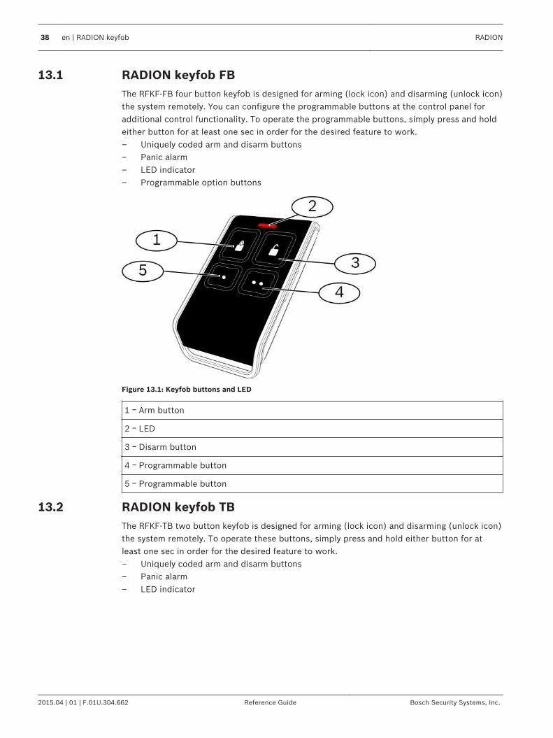
RADION keyfob FBThe RFKF-FB four button keyfob is designed for arming (lock icon) and disarming (unlock icon)the system remotely. You can configure the programmable buttons at the control panel foradditional control functionality. To operate the programmable buttons, simply press and holdeither button for at least one sec in order for the desired feature to work.– Uniquely coded arm and disarm buttons– Panic alarm– LED indicator– Programmable option buttons
Figure 13.1: Keyfob buttons and LED
1 ᅳ Arm button
2 ᅳ LED
3 ᅳ Disarm button
4 ᅳ Programmable button
5 ᅳ Programmable button
RADION keyfob TBThe RFKF-TB two button keyfob is designed for arming (lock icon) and disarming (unlock icon)the system remotely. To operate these buttons, simply press and hold either button for atleast one sec in order for the desired feature to work.– Uniquely coded arm and disarm buttons– Panic alarm– LED indicator
13.1
13.2
38 en | RADION keyfob RADION
2015.04 | 01 | F.01U.304.662 Reference Guide Bosch Security Systems, Inc.
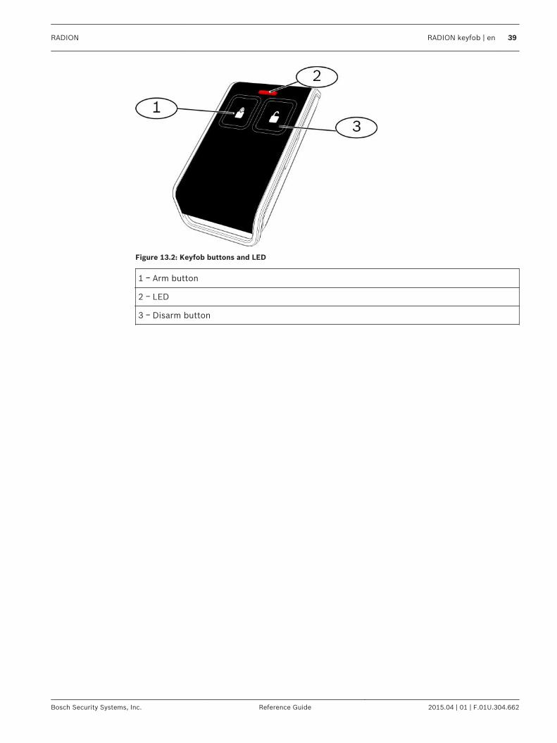
Figure 13.2: Keyfob buttons and LED
1 ᅳ Arm button
2 ᅳ LED
3 ᅳ Disarm button
RADION RADION keyfob | en 39
Bosch Security Systems, Inc. Reference Guide 2015.04 | 01 | F.01U.304.662
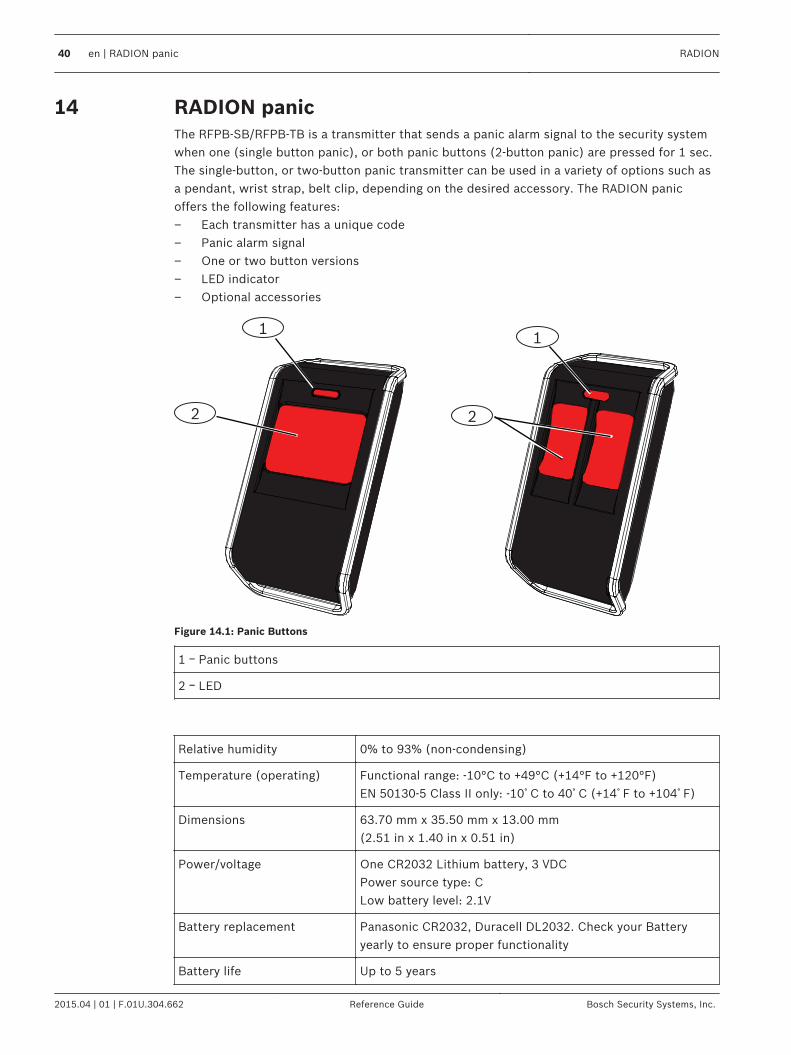
RADION panicThe RFPB-SB/RFPB-TB is a transmitter that sends a panic alarm signal to the security systemwhen one (single button panic), or both panic buttons (2-button panic) are pressed for 1 sec.The single-button, or two-button panic transmitter can be used in a variety of options such asa pendant, wrist strap, belt clip, depending on the desired accessory. The RADION panicoffers the following features:– Each transmitter has a unique code– Panic alarm signal– One or two button versions– LED indicator– Optional accessories
2
11
2
Figure 14.1: Panic Buttons
1 ᅳ Panic buttons
2 ᅳ LED
Relative humidity 0% to 93% (non-condensing)
Temperature (operating) Functional range: -10°C to +49°C (+14°F to +120°F)EN 50130-5 Class II only: -10゚C to 40゚C (+14゚F to +104゚F)
Dimensions 63.70 mm x 35.50 mm x 13.00 mm(2.51 in x 1.40 in x 0.51 in)
Power/voltage One CR2032 Lithium battery, 3 VDCPower source type: CLow battery level: 2.1V
Battery replacement Panasonic CR2032, Duracell DL2032. Check your Batteryyearly to ensure proper functionality
Battery life Up to 5 years
14
40 en | RADION panic RADION
2015.04 | 01 | F.01U.304.662 Reference Guide Bosch Security Systems, Inc.
LED Red
Frequency 433.42 MHz
Table 14.1: Specifications
Notice!
Please note, the battery does not come installed. Verify that the correct battery as defined in
the specification table is installed in the proper polarity.
Optional Accessories
Pendant Pendant transmitters provide single or two-button activation confirmed byemitting LED flashes with all transmissions to clearly show users when the unitis operating. Users can wear the pendants on a neck cord. The pendants areideal to meet the needs of patrolling guards, bank employees, and retail storeemployees.
Belt Clip Belt Clip transmitters provide single or two-button activation confirmed byemitting LED flashes with all transmissions to clearly show users when the unitis operating. The single‑button design is ideal for assisted living installationswhereas the two‑button design reduces accidental activation.
Wrist Strap Wrist Strap transmitters provide single or two-button activation confirmed byemitting LED flashes with all transmissions to clearly show users when the unitis operating.
RADION RADION panic | en 41
Bosch Security Systems, Inc. Reference Guide 2015.04 | 01 | F.01U.304.662
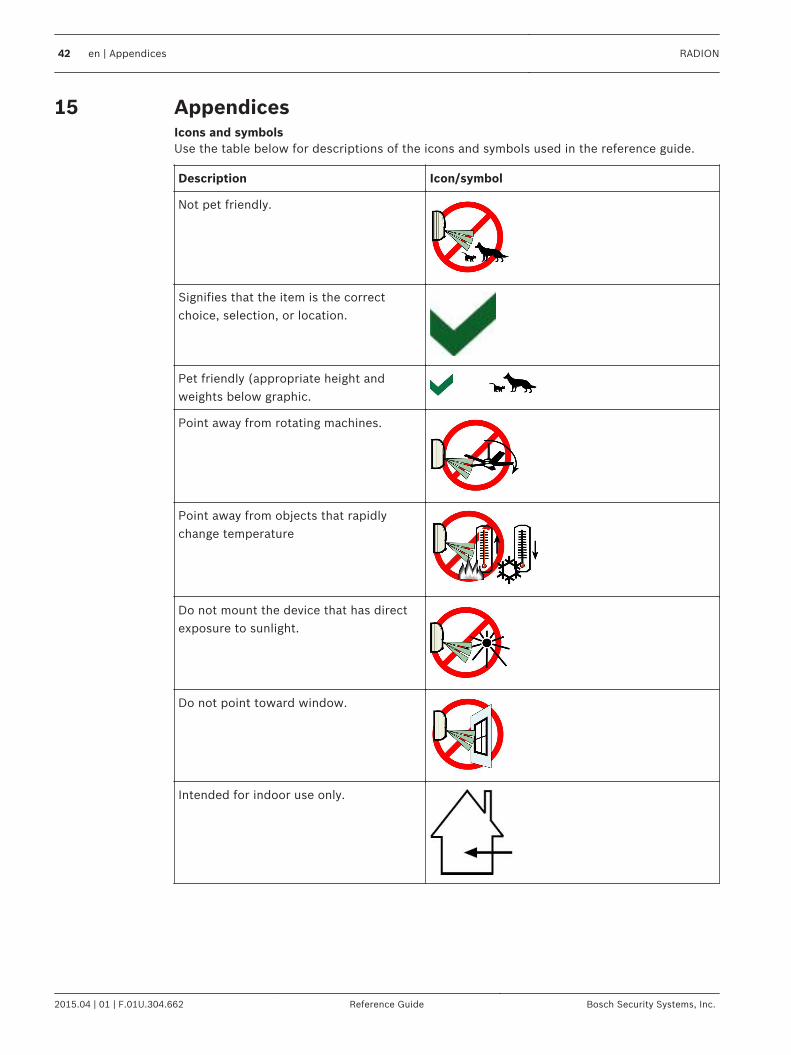
AppendicesIcons and symbolsUse the table below for descriptions of the icons and symbols used in the reference guide.
Description Icon/symbol
Not pet friendly.
Signifies that the item is the correctchoice, selection, or location.
Pet friendly (appropriate height andweights below graphic.
Point away from rotating machines.
Point away from objects that rapidlychange temperature
Do not mount the device that has directexposure to sunlight.
Do not point toward window.
Intended for indoor use only.
15
42 en | Appendices RADION
2015.04 | 01 | F.01U.304.662 Reference Guide Bosch Security Systems, Inc.

Electrostatic discharge symbol
Symbol against disposing batteries intothe garbage
Humidity range
Temperature range
Frequency range
Duration of time
Questions are answered in the referenceguide.
Universal sign for connecting ordisconnecting power.
Universal sign for connecting to a powersource.
RADION Appendices | en 43
Bosch Security Systems, Inc. Reference Guide 2015.04 | 01 | F.01U.304.662

Battery-related information.
Perform a walk test
Walk test has concluded
Device has wall tamper detection.
44 en | Appendices RADION
2015.04 | 01 | F.01U.304.662 Reference Guide Bosch Security Systems, Inc.


Bosch Security Systems, Inc.130 Perinton ParkwayFairport, NY 14450USAwww.boschsecurity.com© Bosch Security Systems, Inc., 2015
Bosch Sicherheitssysteme GmbHRobert-Bosch-Ring 585630 GrasbrunnGermany