radio service hints
TRANSCRIPT

Vol. 6 MARCH, 1942 No.3
CORNELL-DUBILIER ELECTRIC CORP. HAMILTON BOULEVARD SOUTH PLAINFIELD, N. J.
BUY UNITED STATES SAVINGS BONDS ANDSTANPS
Leon Nine East Orange St.!, Lititz pa.
Sec. 562, P. L.&R. U. S. POSTAGE
PAID So. Plainfield, N. J.
Permit No. 1

RADIO SERVICE HINTS Practical Suggestions on Solution of Radio Servicing Problems
Encountered in Actual Experience by Servicemen Everywhere
This section, conducted by our servicemen readers, will be a regular feature of the C-D Capacitor, and is intended to provide other servicemen with helpful notes on testing, locating troubles in specific models of sets, repairing them, or any other suggestions to simplify service work.
Cornell-Dubilier will pay $2.00 for each hint published in this section. Notes must be limited to 75 words, or less. Any number of hints may be submitted at one time. Unpublished items will not be returned. Be sure to give your name and mailing address. Send hints to: Editor, C-D Capacitor, Cornell-Dubilier Electric Corp., So. Plainfield, N. J.
War Effort and Repair Parts
FROM all of our contacts with the officials at Washington, there has been a constant indication that the government feels it is highly desirable to keep in running order the sixty-million radio receiving sets in 87% of the American homes.
The probabilities are that the government will require a certifica-tion on the orders for replacement parts that they are to be used for
the maintenance of existing radio sets, not for the building of new equipment. The parts manufacturer will then be allocated his mate-rials and the orders for these replacement parts will be filled.
In the matter of capacitors, it is very likely that servicemen may have to use small paper tubular capacitors to replace the existing mica capacitors, due to the heavy demand for mica by the armed forces.
In the repairing of radio receiving sets it is urged that standard units be used and not special exact-duplicates which require more material and special manufacturing setups, extra time and labor, which during our war effort have a tendency to slow up production on more urgently needed products.
CORNELL-DUBILIER ELECTRIC CORP.,
South Plainfield, New Jersey.
Page 2 N Teo
u. 11.1 „ THE C-D CAPACITOR

R. C. A. Model 45X1 If a set of this type comes in for
repair on account of intermittent operation, a careful check of the output transformer may reveal par-tial short circuit in the primary winding.
The writer had ocoasion to trace trouble in a set for several hours only to find this to be the cause of the trouble. In some cases repair of the transformer winding may be made in the shop, but it is advisable to replace the transformer with a new one for best results. — Floyd E. Smith, Prairie du Rocher, Ill.
Voice Coil Rattle In these days of scarcity of ma-
terials and parts it is often neces-sary to repair the old in order to give prompt service. One of the major service headaches has always been speaker rattle caused by a de-fective voice coil.
This rattle is often caused by loose turns on the voice coil mounted on th apex of the cone. To remedy
remove the cone from the speak-v..' and cover the voice coil winding with a thin coat of clear lacquer which can be purchased at any paint store. While this is drying, remove all particles on the speaker pole pieces with a piece of sticky friction tape. After replacing and recentering cone it will be found in most cases that the speaker performs as well as new. —Ralph Hunter, Catskill, N. Y.
Emerson 1941 Models In various makes of Emerson 1941
models all tubes may be found to check O.K. but the pilot light fails to light. In some cases the lamp may be burned out.
The remedy found by the writer was to replace the 35Z5-GT tube which developed an open circuit at the pilot light tap of the filament circuit. A tube tester is not apt to
show this on test but in any event it is recommended that the 35Z5-GT tube be replaced with a new one.— Lewis Kanoy, Winston-Salem, N. C.
Resistor Cord Repair In keeping with servicemen's ef-
fort to conserve parts and materials the writer suggests careful inspec-tion of line cords on sets which are found to be open. Many shops merely replace cords without con-sidering that a cord may often be easily repaired.
After careful inspection of open line cords on numerous sets, in most cases the resistance wire will be found broken at the connection to the plug. Making a new connection or resoldering the break in the re-sistor wire will in most cases remedy the trouble completely and satisfac-torily. A new plug may be necessary, but care should be taken not to shorten the resistor wire so much as to affect the efficient operation of the set. — George Vesley, Chicago, Ill.
Method of Mounting Speaker Cones
One of the greatest difficulties many service men experience when re-assembling a speaker is in holding the outside rim of a cone in place on the speaker frame while the ce-ment is drying. The method em-ployed at our shop never fails to line up the cone perfectly.
After shims are placed on pole pieces of the speaker, the cone is lined up around the outer rim of the cone and cement applied on the speaker frame. The rim of the cone is then pressed in place carefully and held with several spring-type wood clothes pins. For small cones six or eight pins are required, but for larger cones ten or twelve are required to do a good job. — Tony Zaccone, Stoneham, Mass.
MARCH, 1942 Page 3

THERAD I 0 ---TUDING-POS
. . ..a ••...iga«ega•
A Free Market-Place for Buyers, Sellers, and Swappers. These advertisements are listed FREE of charge to C-D readers so if there is any-
thing you would like to buy or sell; if you wish to obtain a position or if you have a position to offer to C-D readers, just send in your ad.
These columns are open only to those who have a legitimate, WANTED, SELL or Sint-AP proposition to offer. The Cornell-Dubilier Electric Corp. reserves the right to edtt advertisements submitted, and to refuse to run any which may be considered un-suitable. We shall endeavor to restrict the ads to legitimate offers but cannot assume any responsibility for the transactions involved.
Please limit your ad to a maximum of 40 words, including name and address. Ad-vertisements will be run as promptly as space limitations permit.
FOR SALE — New and used receiving and transmitting parts and equipment. What can you use. Send stamp for list. Herman Yellin, 351 New Lots Ave., Brooklyn, N. Y.
WANTED — Instructograph, with tapes, in good condition or similar code machine. Have Shure Xtal mike, chemical appa-ratus, etc. All letters answered. Ray-mond H. Ives, 822 Windsor Ave., Nor-folk, Va.
WANTED — A good Signal Generator. State price and condition. No junk wanted. Am willing to pay a fair price. Write to Arthur A. Hale, 357 East Park Blvd., Akron, Ohio.
FOR SALE — Used parts for all makes and models of radios. Obsolete and scarce parts. Please order by make and model of set and part number. Martin L. Pitts, Terrell, Texas.
WANTED — Vacuum Tube Voltmeter, Signal Tracer, Rider's Manuals, and condenser tester. Will pay cash. Law-rence Chronister, Paola, Kan.
PERSONAL — Will the man from Plymouth, Wis., who was interested in radio equip-ment, and called on me Feb. 19, kindly write me as I have some things he can use. Oliver F. Klein, c-o O K Radio Service, 2235 N 39th St. Milwaukee, Wis.
FOR SALE — One Hickok Tube Checker, counter model Na. 46, takes all tubes to 30 volts. Like new with adapters for many new tubes. One Triplett Counter Portable Tube Checker, like new, model No. 430 with Locktal adapter. What do you offer? Leading Radio, 114 E. 3rd St., Mt. Vernon, N. Y.
FOR TRADE — Communication Engineer-ing, Everitt; High Frequency Measure-ments, Hund; Radio Engineering Hand-book, Henney; Theory of Thermionic Vacuum Tubes, Chaffee. Will trade for Rider's Manuals number 5, 6, 7 and 8 or later issues. Nathan Glenner, 1695 Gladstone Ave., Detroit, Mich.
SELL OR SWAP — Have Shure Uniplex microphone; 40 meter crystal; 807 trans-mitting tube; Thordarson phono ampli-fier; power transformers. All in excellent condition. Want meters, recording equipment or what have you. Bob Joies, 236 N. Palm, Upland, Calif.
FOR SALE OR TRADE — 2 Majestic Elim-inators A and B (A not assembled) both 110 volt 60 cycle A.C.; B No. M28642 60 Mils at 180 volts; A No. 12628 6 volts at 21/2 amps max. Also No. 245 Readrite Portable Analyzer tee tubes and A.C. or D.C. volts, ohms, and mils. Need beginners' short wave receiver (A.C. preferred) complete with plug in coils and tubes. Russell D MacPherson, 118-02 101st Ave., Richmond Hill, L. I., N. Y.
WANTED — RFO-5 Hickok Oscillograph or 560A Supreme Vedolyzer and 561 Supreme Oscillator. State condition, tubes used and price. O. F. Hamm, 4751 Louisiana Ave., St. Louis, Mo.
FOR SALE — Triplett V.O.M. and Triplett signal generator, excellent condition, late model. Also lessons, diagrams, tubes and parts. Write for particulars. Arthur W Albee, Oshkosh, Neb.
FOR SALE — One Echophone receiver model EC-1, used about 6 months, in good condition. Will take $17 cash. Dyer Matlock, Jr., Box 423, Mt. Pleasant, Tenn.
(Continued on page 14)
Page 4 THE C-D CAPACITOR

INDUSTRIAL ELECTRONICS*
Since so many radio service men are now engaged in industrial fields on work for war needs, this article by Mr. Alfred A. Ghirardi, author of "Modern Radio Servicing," "Radio Troubleshooters Handbook," "Radio Physics Course," etc., should be especially helpful as it shows the functions of capacitors in electronic equipment.
Equipment to control welding operations in which conditions make it necessary to limit the application of welding current to a tiny fraction of one second is described in detail with circuits and operating data.
Split-Second Weld Timer
In the manufacture of radio tubes the high current required to make a satisfactory weld can not be applied for any appreciable length of time without burning up or otherwise dam-aging such small parts as grids, fila-ments, etc., or at least causing them to stick to the welding electrode. The welding timer to be discussed is one used by tube and lamp manufacturers and is shown removed from its case in Fig. 1. Its schematic circuit appears in Fig. 2.
The tube VT1 is a type C6J grid-controlled rectifier manufactured by Electrons, Inc., and is capable of de-livering up to '77 amps (peak) in continuously recurring pulses, up to 12.8 amps d-c continuously for periods up to 3 seconds, and up to 6.4 amps d-c for unlimited periods. Maximum a-c short-circuit current rating is 770 amps for a period not exceeding 0.1 second. It is for use in circuits from 110 to 440 volts, with peak forward voltages to 750 and peak inverse volt-ages to 1250. Its filament draws 18
* By Alfred A. Ghirardi in "Service."
The Weltronic special tube checker which not only provides conventional quality tests but gives fairly extensive analysis of various operating charac-teristics of thyratrons, gas and vacuum rectifiers and high-vacuum control tubes. Indications are provided on a meter and on a l-in. cathode-ray tube.
amperes at 2.5 volts. With peak for-ward voltage applied to the anode, a grid voltage of minus approximately 3.5 will prevent firing. As in the case of other thyratron type tubes, the grid loses control completely when the tube fires and can again gain control only when the anode voltage is cut off or reduced substantially to zero.
In the circuit of Fig. 2, this tube functions as a heavy-duty relay through which the welding current flows direct-ly from the 220-volt a-c line. This 220-volt supply is applied to the tube continuously but current cannot flow while switches A and B of the start-
MARCH, 1942 Page 5

ing relay (actuated by a foot switch at the welder) are closed, for the rea-son that voltage from this same source, but reduced to 55 volts by the step-down transformers, is applied to the grid of the tube 180 degrees out of phase with the anode voltage. Thus the tube cannot conduct when the anode voltage is positive because the voltage applied to the grid is then negative; and when the anode voltage is negative or only slightly positive there can be no conduction even though the grid is highly positive at that point in the cycle.
Fig. 1. An automatic control unit through which applications of welding current are limited to single impulses of less than 1/120 second. The tube in the foreground is the type C61
discussed in the text.
This is made clear from the curves Bi,, E, and E, of Fig. 3. Here the curve Ege represents the critical grid voltage which just barely will prevent the tube from firing for the correspond-ing value of anode voltage. In other words, for the tube to fire at any point in this positive half-cycle, it is neces-sary for the grid to be more positive than the value indicated by Ege at that point. With the anode and grid volt-
ages exactly out of phase, it is appar-ent that firing cannot occur. On the other hand, suppose that the
phase relationship were altered, in effect moving E, along the horizontal axis to E. The applied grid voltage then rises above the critical value dui--ing a few degrees near the beginning of the half-cycle, as indicated by A and B.. To the left of point A the anode voltage is too low to fire. When the switch at the welder is
depressed, the starting relay (Fig. 2) opens switches A and B. In the case of A, this places 11, in the circuit, and this resistor, in conjunction with con-denser C,, shifts the phase relationship between the grid and anode sufficiently so that at the beginning of the next positive half-cycle of anode voltage the tube will fire. Should the switch by coincidence be depressed at an instant between the points AB of Fig. 3, the tube will fire immediately and current will flow during the remainder of that half-cycle. If depressed dur-ing the time interval between B and C, or between C and the point on the next positive half cycle correspond-ing to A, the tube will not fire until this point is reached. Thus the tube can fire only during the first few degrees of the positive anode cycle. Once it fires, current flows until the end of that half cycle. It is therefore ap-parent that the current flow will al-ways be of the same duration—just slightly less than one-half cycle—re-gardless of when (on the time-voltage characteristic) the welder switch is depressed. Nor can the current again flow until
the switch has again been depressed for another weld. The reason is that when the tube fires the condenser C2 becomes charged by virtue of the fact that one side is connected (for that instant) to the positive side of the 220-volt supply (the drop across VT1 is negligible), while the other side returns to the negative side of the sup-ply line through the rectifier, VT2. When the welder current ceases at the end of the half-cycle, VT2 prevents discharge of the condenser and its maintained charge therefore places a
Page 6 THE C-D CAPACITOR

220 V LINE
VT2 .4>
high negative bias on the grid of VTI, thereby preventing further firing even though the switch at the welder may be held down for an extended period of time. Once this switch is released, closing
the relay contacts A and B, the con-denser discharges through contact B and the resistor R2. At the same time, the phase-shifting network Ili, Ci is made inoperative because contact A shorts out 111. The initial 180-degree out-of-phase relationship is thus re-established and the tube cannot again fire until the control switch is de-pressed by the operator for the next weld.
It is necessary that the anode and grid supply voltages of this set-up be drawn from the same a-c line to insure maintenance of the desired phase re-lationship. In this particular instance, two transformers (T, and T2) are em-ployed to step the 220-volt welder sup-ply line down to 55 volts. A single 220-55 volt transformer would serve
Fig. 2. Circuit of the automatic control unit shown in Fig. I. The device is capable of delivering instantaneous current of several hundred amperes to the welder for the split second. It is manufactured by Callite Tungsten Corporation.
SUPPLY TO WELDER
TO SWITCH ON FOOT CONTROL AT WtLoCR
110V
110y
o
o
as well, the two actually being used as a matter of manufacturing convenience.
Interval Timer The emphasis on gaseous tubes of
the thyratron type may tend to create the mistaken impression that, more or less, all industrial electronic installa-tions make use of them. Such is far from the case, however. There are innumerable industrial equipments em-ploying little, if anything, with which every Service Man is not already fa-miliar. An interesting example of such de-
vices is an interval timer employed in the research laboratories of the Callite Tungsten Corporation for determining the number of on-off cycles to which experimental neon and fluorescein lamps can be subjected before break-down. To serve the purpose, each "on" period must be sufficiently long to bring all components of the lamps up to normal operating temperature; the "off" period long enough to provide
MARCH, 1942 Page 7

The Worner Anti-Sabotage equipment. invisible light beam for the photoelect
produces audible
adequate cooling. A 71/1-minute cycle has been adopted-6 minutes "on" and 11/2 minutes "off." The function of the electronic timer is to apply and cut off power at these intervals, and
Fig. 3. The CSI tube can fire only during the first few degrees of the positive anode cycle. Once it fires current flows until the end of that
cycle.
do it automatically day after day and week after week. The circuit of this device is shown in Fig. 4.
"Black" light source (right) provides rie relay at left. Interruption of beam or visible alarm.
The actual switching is performed by a relay operated by the plate cir-cuit of an ordinary radio tube, a type 43. The timing is automatically con-trolled by charging and discharging a condenser through resistors in the grid circuit of this tube. This varies the bias sufficiently to operate the relay at the required intervals. A 25Z5 voltage-doubler is employed
as power supply for the 43 tube. On a line voltage of 120, the device pro-vides an output of approximately 300 volts across the pair of doubler con-densers, with 150 volts across each, as shown. The 43 is so connected that its cathode is about 150 volts and plate plus 300 volts, in respect to the low side of the supply. Thus the grid can, for control purposes, be made considerably negative in respect to cathode. The relay is normally in position 2,
in which power to the load is off and the 43 grid is biased only by the value across the cathode resistor. As current flow is established, it exceeds the amount (10 ma) required to operate the relay with the result that it as-sumes position 1, applying power to the load and connecting the grid con-denser C, across 150 volts through the 100 meg of R,. This causes C, to charge slowly, gradually increasing the bias applied to the grid of the 43
Page 8 THE C-D CAPACITOR

Fig. 4. The circuit is that of an interval timer employed to determine the number of off-on cycles to which certain neon and fluorescent tubes can be subjected
before breakdown.
and accordingly reducing the plate current. In 6 minutes, Ci charges to a value which reduces the plate current to 5.5 ma., at which value the relay drops to position 2, disconnecting the load.
operating current-4 to 20 ma.; oper-ating voltage-65; external series re-sistor must be such as to limit current through the lamp to 20 ma. Glow lamps are also available without in-ternal resistors. These are the most
I I o TO LOAD 110V. A.D.
In this position, C, discharges slow-ly through 20 meg (R2) thus grad-ually reducing the negative bias on the grid with the result that at the end of 11/2 minutes plate current is again sufficiently high to throw the relay to position 1, initiating another cycle of operation. The voltage regulator circuit through
which C, draws its charging voltage represents an interesting application of standard 2-watt neon glow lamps. If the resistors included in the bases of such lamps are removed and a suitable external resistor is then connected in series with the lamps, the result is a voltage divider in which the voltage across the lamps remains substantially constant despite wide variations in the current drawn by a load connected across them. They function in a manner similar to tubes of the VR series and have the following approx-imate ratings: starting voltage-75:
practical for this service and are sup-plied with small bayonet bases to dis-tinguish them from the type with the internal resistors (which have stand-ard screw bases). The purpose for which this device
is employed does not call for extreme precision of timing, therefore all com-ponents are ordinary radio parts, ex-cept that Ci, C2 and C3 are paper ca-pacitors rather than electrolytics. Pre-cise regulation of all supply voltages, the use of high-grade capacitors (espe-cially for C,) and specially treated re-sistors help to provide higher accuracy and dependability. A mechanical contrivance could un-
doubtedly be designed to accomplish this same purpose, although this would be somewhat complicated and far more expensive than this electronic device, would be subject to wear, and would re-quire more maintenance attention. Furthermore, should it be desired to
MARCI-I, 1942 Page 9
change the timing cycle to meet the requirements of different types of lamps under test, it would only in-volve minor changes in the C1, Ri, R2 circuit of this electronic timer, whereas with a mechanical control unit, the required changes would be major ones and might even necessitate replacement of the entire unit.
Photon.le Devices Phototubes are employed in many
industrial applications for an almost unbelievably wide variety of purposes. Electric signs or street lights are turned on automatically when waning daylight,
as registered on a phototube, falls be-low a predetermined level; and are usually turned off again by the same phototube-actuated devices at day-break. Colors are compared; an alarm is given when chimneys smoke ex-cessively; labels or wrappings in me-chanically packaged products are auto-matically lined up and registered; light values are measured; the transparency or turbidity of materials and fluids is measured; buildings and properties are protected from theft or sabotage by beams of light; objects are counted or sorted by sizes and shapes—to cite just a few of the applications in which
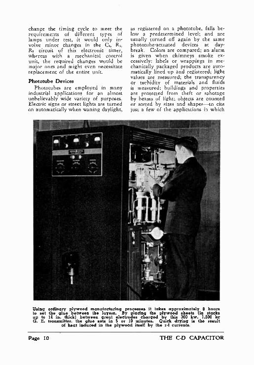
Using ordinary plywood manufacturing processes it takes approximately 8 hours to set the glue between the layers. By placing the plywood sheets (in stacks up to 14 in. thick) between great electrodes charged by this 300 kw, 1,500 kc G. E. transmitter, the glue sets in 5 or 10 minutes. Quick drying is the result
of heat induced in the plywood itself by the r-f currents.
Page 10 THE C-D CAPACITOR

phototubes actuate measuring or con-trol mechanisms as a result of varia-tions in direct or reflected light.
Normally the output of a phototube is not in itself sufficient to operate switches, relays or other mechanisms because the maximum anode current available even under extreme values of illumination seldom exceeds 20 microamperes. It is therefore the uni-versal practice to employ some form of amplifier to build up the phototube impulses. Where a simple off-on oper-ation is to be performed, such as in actuating a power relay, for instance, or in stopping or starting appreciable current flow to any other device, it is common practice to employ gas tubes of the thyratron type for this amplifying purpose. These tubes are, in effect, highly sensitive electronic relays by means of which the tiny phototube outputs applied to their grids enable them to control very much larger values of current in their anode circuits.
In Fig. 5 is shown a fundamental phototube circuit in which a thyratron or relay tube is employed for the pur-pose of energizing a power relay when the light acting on the phototube ex-
Fig. 5. The photoelectric tube circuit shown will operate a relay when the illumination exceeds a predetermined value. This value is adjusted by
means of the resistor R3.
ceeds a certain predetermined level. This device functions directly from the a-c line, and operates only on the
Fig. 6. The photoelectric ube circuit will operate a relay when the illumi-nation falls below a certain pre-determined value. This device usually is used in conjunction with a light
source.
half cycles during which the upper side of the line is positive. With no light applied to the phototube, the grid of the 2051 thyratron is maintained negative in respect to its cathode by the potential drop between points A and B of the voltage divider network. With light applied to the phototube, however, the photoelectric current flow through R, tends to apply a positive bias on the grid of the relay tube, thus partly offsetting the existing negative bias. As the light is increased a point is reached where the drop across R, due to photoelectric current flow is sufficient to cause the thyratron tube to fire. The light value at which this occurs is determined by the adjust-ment of the potentiometer R,.
Once the thyratron tube fires, it will continue to be conductive during the balance of that half cycle, and during succeeding alternate half cycles so long as the light remains above the triggering level. These half-cycle im-pulses will excite the relay in the anode circuit of the 2051, and thereby
MARCH, 1942 Page 11

operate the relay contacts. The ca-pacitor (C) across the relay winding may be necessary to prevent chattering of the contacts due to the pulsating excitation impulses.
Fig. 6 shows a similar circuit but one in which the phototube is so connected that the controlled relay will receive excitation only when the light falls below a predetermined value.
Here the grid of the 2051 is nor-mally biased positive (during half cycles when the upper side of the line is positive) in respect to its cathode by virtue of the voltage distribution along the divider R2, R1 and R1. At least this is the case when no light falls on the phototube (and its re-sistance is therefore substantially in-finite). Under these conditions the 2051 will fire during each half cycle when its anode is positive and the relay will therefore be energized. When light falls on the phototube, however, the photoelectric current flow causes a voltage drop across R. The direction of this current flow is such that the grid of the 2051 becomes more negative in respect to the slider end of R, and therefore less positive, or even negative, in respect to the cathode of the 2051. Under the influence of appreciable
light values, the voltage applied to the grid will prevent the 2051 from firing. As the light decreases a point is reached, determined by the adjust-ment of the slider of R2, where the tube will fire. The circuits of Fig. 5 and 6 are
fundamental ones which provide wide flexibility of application. This flexi-bility is indicated by the fact that either one can be employed to either apply power to the load or cut off the power when the illumination on the phototube exceeds any prede-termined value, or when it falls below this value. Thus the circuit of Fig. 5 will not only excite the relay when illumination exceeds the value for which R, is adjusted, but will drop out the relay when light falls below this value. The functioning of the circuit of Fig. 6 is just the reverse.
The mechanical relay may be one which opens the controlled circuit when current flows through its coil, or one which closes the load circuit when its coil is energized. Or it may be one which closes one or more cit.-cuits when energized and which opens these and closes other circuits when de-energized. Thus there is almost no limit to the functions that can be controlled by these two simple cir-cuits. Nor is it by any means essen-tial that a mechanical relay be used at all. The current flowing in the anode circuit of the thyratron can in many cases be applied directly to the circuit to be controlled. In the split-second welder discussed earlier, for in-stance, this is done. In that instance the thyratron tube was not actuated by a phototube but the principle re-mains the same.
In most applications of equipment utilizing a phototube-controlled thyra-tron the power is obtained directly from the a-c lines without resorting to any form of rectification (other than that provided by the fact that both the thyratron and the phototube are themselves funchmentally rectifiers) or filtering. Even a transformer may be necessary only where the use of a phototube of the vacuum type may require higher anode voltage than that supplied by the line, or where the volt-age applied to the controlled load by the thyratron must be higher than the line value, etc. Thus the design of these automatic control units is both simple and economical. The forego-ing, coupled with the high control factor, low grid current (which per-mits the associated phototube to be operated with a high load resistance, and therefore at high sensitivity), and high output of thyratrons, make them ideal for many anplications.
Because the thyratrons recycles it-self automatically on alternate half cycles of the supply current, its opera-tion from an a-c source offers obvious advantages. It can also be employed on d-c supply providing it is required to perform but a single operation. It will not recycle on d-c. In other words, once the tube fires it will re-
Page 12 THE C-D CAPACITOR

main conductive unless some external means is provided to reduce its anode voltage to substantially zero. This can be accomplished by means of a hand switch or relay to momentarily break the anode circuit, or by special automatic arrangements. Because these are likely to be complicated and rela-tively expensive, thyratrons are less commonly used in d-c circuits involv-ing repeat operations. Where the output of a phototube
device is required to reflect continuous variations in photocell illumination, as in the reproduction of sound from film, in light measurement work, etc., the thyratron cannot be used because it is essentially an off-on relay which knows no intermediate steps between its full conduction and no conduction condition. In set-ups which involve varying degrees of output, therefore, standard radio tubes and standard tube amplifier circuits find wide application. Radio Service Men are already fa-miliar with such circuits and discussion here of circuit details is not deemed necessary.
Before closing the present article it might be well to point out one field of importance which the average Serv-ice Man is quite qualified to tackle immediately. That is the installation and servicing of burglar-alarm types of phototube protective devices. At no time in the history of in-
dustry has automatic protection of property been as essential as it is now. During the last war industrial plants went in heavily for brilliant flood-lighting of their properties as a means of night-time protection, extensive fencing for day and night protection, and large forces of guards and watch-men. Such a combination of pro-tective measures was effective although extremely expensive.
In the present emergency the con-ditions with which the plant owner is faced are quite different. They now not only have to guard against sabotage but against possible attack by enemy bombing planes. Exterior floodlights are therefore of vastly decreased use-fulness for the reason that they must be extinguished in blackouts—at the
very time when protection may be most needed. In inky blackness, guards are effectively blinded and no fence is unscalable. By far the most effective protection aid obtainable is that pro-vided by a carefully designed net-work of phototube equipment inter-cepting light beams which are so di-rected as to weave an impregnable skein around the industrial plant and within the plant as well. Such a sys-tem can utilize invisible light (so called "black light") powered by batteries or by a small local generator. Thus neither blackouts nor failure of power lines can interfere with its effective-ness.
Commercial protective equipment of this type is available in which a light source and the phototube unit may be placed up to several hundred feet apart. An intruder passing between these will intercept the light beam thus sounding a general alarm or providing a silent signal, depending on the re-quirements for which the system was designed. Such a system can be ar-ranged to indicate in which of the protected areas the intruder is present and can give this indication in the main office or at as many guard houses or other points as may be desired.
Equipment for shorter light throws may be such that the light source and phototube receptor are in a single case. This is a more economical ar-rangement as it reduces both installa-tion and equipment cost. With such equipment the beam of light is di-rected on a distant mirror which re-flects it back to the phototube. By suitably shielding the phototube and mirror and by use of a fairly power-ful light source, such a protective sys-tem can function in daylight as well as in darkness. This is, of course, also true of systems in which the light source and phototube equipment are separate units. Either therefore af-fords 24-hour protection. Complete directions for installing
commercial phototube protective sys-tems are available from manufacturers of phototube equipment and they are glad to co-operate in the planning of a system best suited to the regulations
MARCH, 1942 Page 13

of an individual plant or property. Such co-operation is an important aid to a radio Service Man who is just entering the field and this, plus his general electrical and radio ingenuity, qualifies him to undertake installations without extensive preliminary training.
Maintenance of these protective systems is also a worthwhile element of the business. Lamps employed as light sources are often rated for a specific life and in order to avoid a breakdown in the system should be replaced regularly at intervals usually less than this rating. Where the lamps and the tubes involved render 24-hour service a complete checkup at least once a month is desirable. For this reason this sort of work lends itself to a flat monthly maintenance charge.
The following list of books and papers offers helpful study and refer-ence material for the Service Man who is really desirous of gaining a thorough working knowledge of the practical and theoretical considerations involved in industrial phototube applications. This list is published through the cour-tesy of the RCA Manufacturing Com-pany.
References
Photoelectric Cells, by Campbell and Ritchie; Isaac Pitman & Sons, Ltd.
Industrial Electronics, by Gulliksen and Vedder; John Wiley and Sons, Inc.
Electronic Tubes in Industry, by Kieth Henney; McGraw Hill Book Co., Inc.
Photoelectric Phenoenena, by Hughes and DuBridge; McGraw Hill Book Co., Inc.
Application of Conventional Vacuum Tubes in Unconventional Circuits, by F. H. Shepard, Jr.; Proc. I.R.E., Dec., 1936.
Some Unconventional Vacuum Tube Circuits, by F. H. Shepard, Jr.; RCA Review, Oct., 1937.
Photocells and Their Applications, by Zworykin and Wilson; John Wiley and Sons, Inc.
THE RADIO TRADING POST
(Continued from page 4)
TRADE — Have a Clough Brengle 88A VTVM cost $50. Will trade for Triplett Modulation monitor, Abbott MRT or TR-4, Hallicrafters HT-7, Browning Fre-quency Meter, or good amateur re-ceiver. Walter Kryger, 912 W 151 St., East Chicago, Ind.
WANTED — Rider's chanalyst, must be in A-1 shape and cheap for cash. Southern Radio Service, Thomasville, Ga.
WANTED — Factory built all-wave re-ceiver any make. Age, cabinet or condition no object just so it is com-plete. Also want testing equipment any description. All letters answered. Glenn Watt, 415 W 1st St., Chanute, Kan.
WANTED — Rider's Manuals 1 to 12. Must be in good condition. Any or ail with index and supplements. Thos. Squartino, 572 N 7th St., Newark, N. j.
FOR SALE — Hi standard model C target pistol, with eh" barrel. Practically new, fired only a few times. New Red Head holster included. Will send ex-press collect $19.50. Will send subject to inspection if requested. Malcolm D. Burdick, Hampton Station Road, Hamp-ton, Conn.
FOR SALE OR TRADE — Rider's Manuals 1 to 12 with supplements, Triplett meters, tube checker, signal tracer, oscillator, condenser decade box, tubes, speakers, all parts. AC.-D.C. power drill, as-sorted tools. Send stamp for list. Al's Radio Service, 460 Atlantic St., Stam-ford, Conn.
HAVE German Folding Fine Camera using 120 film F3.8 lens F.10CM Compur Shutter. Best offer. Want C-D Capac-itor analyzer Model BF50 in trade. W. S. Crooks, Gen. Del., Akron, Ohio.
WANTED — Custom built radio for 1936 Ford V-8, also recording equipment, television receiver and Jenson type J dual loudspeaker. Have complete NRI radio course $29.50, forty popular dance phono records, 15c each. E. P. Schoen-eck, Route 2, Box 16, W.:11peton, N L)
FOR SALE—Tubes, cona .esistors, vacuum controls, transfo. mers, channel analyzer, tube tester model 307, Salor Capacitor analyzer model CB-160. Stan-cor power pack, de luxe model, bulb type battery charger.. Clarence W. Hull, Mineral Springs, Pa.
WANTED — Will pay cash for Rider's Manuals 1, 2, 4, 5, 7, 8, and 12, radio books, manuals, course, test equip-ment, dynamic tube tester, multi-tester, ohmmeter, condenser tester. Kays Radio Service, 3191/2 Main St., Niagara Falls, N. Y.
Page 14 THE C-D CAPACITOR

WANTED — Weston meters 301 o-100 mils to 0-500 milamps., and Weston 476 or 425 meters. Also any Weston 528 and 489 meters. Leo F. Kersey, B4, White Sulphur Springs, W. Va.
WANTED — We are in the market for a complete set of Rider's Service Manuals. Must be in good condition. Will pay cash. Robertson Radio Service, 2'21 1/2 W. Main St., Greenwood, Ind.
WANTED — RCA Rider Chanalyst. Must be in good condition. Also a RCA volt-ohmmeter, a 912-P Precision portable tube tester 1941 model, and RCA tip file. Paul Copito, 637 21 St., Erie, Pu.
FOR SALE — Al Hickok Radio Tube Tester A.C. 51, $47; Supreme Generator Model 570, $20; Phitoo Signal Generator Model 016, $15; Solar Capacity Resistor Bridge Analyzer, $15; Triplett Milliammeter Model 321, $15; Cornell-Dubilier Capa-city Bridge, $8. Also many books and diagrams. Write for list. Economy Radio Service, 950 Michigan Ave., Ham-mond, Ind.
WANTED — Weston Model 669 Vacuum Tube Voltmeter and good make of Radio Communication receiver. Best cash price paid for same. Radio Repair Service, 173 Main St., Mexico, Maine.
WANTED — Signal Generator, tube check-er, and manuals. Late models. Have H.O. gauge model railroad equipment. engine American Flyer 14 volts A.C., 7 complete cars, 50 feet of track. Curt Stewart, R.F.D. 1, Box 153, Charleston, W. Va.
WANTED — Meters, test equipment ot every description. Radio Technical Laboratories Tube Checker $4.95. Stamp for list. Roby's Swapmart, 3569 Cot-tage Grove, Chicago, Ill.
TRADE — Two 15 watt PA systems, phono motor, phono oscillator one 2 amp. battery charger, one half amp. battery charger, five 2 amp. tungar bulbs, (DST's. Need auto A battery eliminator, tube tester, Rider's Manuals 4 to 12. Stanley, 2748 Meade St., Detroit, Mich.
WANTED — Capehart or RCA record changer which will play both sides suc-cessively, with or without amplifier. State make, model, condition, and price. L. A. Schaffer, 131 N. 24, Camp Hill, Pa.
WANTED — Position in a radio defense factory for young man, ineligible for draft. Graduate of RCA School, but no experience. Willing to learn. Will accept nominal salary, but must have opportunity for advancement. Sidney J. Brass, 560 Beck St., Bronx, N. Y.
CASH — For Rider's, Hickok, Supreme, Superior, etc., Signal Chasers, V.T. voltmeters or meters. State price, con-dition and model. The Simplex Shop, Salina, Kan.
FOR SALE — Clough Bren_gle, Model 105, one-inch oscilloscope. Has everything a big one has: two built-in amplifiers, nine panel controls, connections for transmitter or sweep frequency oscil-lator. Complete with instructions, dia-gram, calibrated screen. Like new. $25. John T. Frye, 1810 Spear Street, Logansport, Ind.
WANTED — General Electric Receiver, 1938, with electric tuning and electric clock program preselector for full week programs. Must be electrically and mechanically perfect. State price and condition. Bates Laboratories, 33 Sun-set Drive, White Plains, N. Y.
FOR SALE — Two Neon Window Signs, four inch letters in red, size approxi-mately 16" x 36", one sign reads "Radio Sales & Service," other sign reads "Electrical Supplies," each sign equipped with heavy duty 110 volt A.C. transformer. Will sell singly or together very reasonable. Write to C. Leslie Purcell, 137 Murray Ave., Goshen, N. Y.
FOR SALE — Hickock RFO4 Oscillograph, Hickock Microvolter, Hickock 210X Zero current voltmeter, Hickock 155 Traceom-eter, Hickock 51X tube checker, Solar Capacitor checker, Wright DeCoster test speaker, Weston 664 AC and capa-city meter, Weston 663 volt ohmmeter. Charles G. Peroz, 46 Commonwealth Ave. Ext., Middletown, N. Y.
FOR SALE — Supreme model 339 de luxe analyzer; A-1 condition, portable carry-ing case; DCV 5-1250, DCMA 5-1250; Ohms 0-2 M. $17.50 cash. Art Radio Service, 1422 7th Ave., Rock Island, Ill.
SWAP — 42 reference books on steam and electrical engineering by the ICS staff, in good shape, for telephone type relay, or radio repair parts, equipment, etc. Morton Radio Shop, 1912 Jerome Ave., Grand Rapids, Mich.
FOR SALE OR TRADE — One army com-munication receiver, one instructograph with oscillator, phone, five tapes and instructions, AC oscillator with speaker in case, misc, radio parts. Want camera, photographic equipment, etc. F. L. Emerson, 71/2 N. Second St., Yakima, Wash.
WILL TRADE—D.C. multimeter, full wave, copper oxide rectifier, Radio Craft maga-zines and parts for experimenting and set building. Want Service manuals, chemical apparatus or what have you? My list for yours. Floyd Goff, Black Mountain, N. C.
FOR SALE — 2 Victor Animatograph Sound-on-film 16MM projectors models 40B and 38. Can be had with either 12", 15", or 8" speakers; A-1 condition. Ideal for Drive-In theaters, roadshows, etc. John J. Spankowitch, 239 N. 9th St., Allentown, Pa.
MARCH, 1942 Page 15

1049 HAMILTON BLVD. • SO. PLAINFIELD, N I. • BRANCH DIVISION NEW BEDFORD,MASS.
Stl.`t \I"‘
I;_ t>, \-\1:2b0.%
— writes E• SEWELL
eirrninghorn, Alo•
C 'I have been using your ftne M condensers
for two years rs do away n-
now and 1 have never had one
fail yet," continues Mr. Sewell, "and, boy, how those CM Blue Beave with that old exact teplacement headache" as
. hu
dreds o and f servicemen have written us just
enthusiastically as Mr. Sewell —because C-D s make satisfied customers but l.d profitable repeat business for you. 'You can standardize on dependable Cornell-D capacitors
ubilier
with confidence. Once you try them, you'll
swear by 'ern'. ON R EQUES T
C ATALOG
MICA • PAPER• DYKANOL. WET AND DRY ELECTROLYTIC CAPACITORS
ELECTRIC CORPORATION
' MORE IN USE TODAY THAN ANY OTHER MAKE