radio propagation through rocket exhaust jets: part 1...
TRANSCRIPT
C.P. No. 764
MINISTRY OF AVIATION
AERONAUTICAL RESEARCH COUNCll
CURRENT PAPERS
Radio Propagation through Rocket Exhaust Jets:
Part 1.
Electromagnetic Wave Propagation in an Ionised
Medium
BY
H. Williams
LONDON: HER MAJESTY’S STATIONERY OFFICE
1965
PRICE 12s 6d. NET

U.D.C. No. 621.336.82 : 621.455.019.9
C.P. No. 764
February, 1959
RADIO FROPACATION TiiROUGH ROCKET EXHAUST JETS:
PART I
ELECTROMAmTIC WAVE PROPAGATION IN AN IONISED
MEDIUM
H. Williams
The attenuation per unit path length, phase shift per unit path length end reflection ooefficient at the boundary are derived theoreticelly for a medium containing free electrons, in terms of the electron density, electron collision frequency with heavy molecules end the applied radio frequency.
Numerical results are tabulated. over wide ranges of the three variables, and these results are also presented gmphically.
Useful. approximdione to the complete theory are derived end the regions in which these my be applied in practice a-e indicated.
----- -
Replaces 4.P.E. Xeport No. 37 - A.R.C. 21 288.

8
LIST OF commrrs ~-
INTRODUCTION
EIXCTROMAGM3TIC PROPAGATION IN A PARTIAL CONDUCTOR
EIECTROKAGWTIC PROPAGATION IN AN IONISED GAS
ATTEXUMION IN A PARTIAL CONDUCTOR
PHASE SHIFT INAPARTIALCONDUCTOR
REFIECTION AT NORMAL INCIDENCE TO THE BOUIQDARY OF APARTIALCONDUCTOR
J..l?l%OXIMATION TO THE SlMpLE THEORY FOR A GbZEOUS MEDIUM
7.1 High values of w,
7.2 Lsw ~8333~ 0f W,
7.3 The reflection coefficient
DISCUSSION
ACKNOWIED~E
REFERENCES
LIST OF SMdDOL3
16
16
18 21
21
23
23
21
26
TiLN.TES I to XXXVII 27-44
ILLUSTIiATIONS - Fig. 1 to U,
DETACHABLF &3%RACJ! CARJX
Explanation of the tables 26
Tables LIST OF TABLES
27-33
33-39
bo-44
=
4
4
7
11
12
12

Tables LIST OF TABLIZ (Cod)
xxxn Approximaticn fcr R at high electron collision frequencies
XXXVII Approximation for R at low electron collision frequenoiea
LIST OF ILT.WTRA!l?IONS
Ccmparison of simple theory with that of bkrgenau
Variation of attenuation with radio frequency for
w, = IO 12 to 106 se0 -1
Variation of phase shift with radio frequency for
0, P lOI to IO6 se0 -1
Variation of power reflection coefficient with radio frequency
for w, E: IO 12 to 407 880 -1
Approximation for R at high electron collision frequencies
Approximation for R at low electron collision frequencies
Variation of phase shift with radio frequency
9 B IO7 seo-' , N P IO'O om-J
2 to 8
9 to 15
16 to 21
22
23
u,
-3-
1 INTRODUCTION
The purpcoe of this paper is to present as simply as possible the gcnerdly accepted theory of clectrmagnetic wave prcpagation in an ionized gas, together with tables cf computed velucs for the attenuatzon, phase shift, snd reflection at the boundary cf such a medium.
The emphasis is placed on the practical use of this theory and to facilitate this, approximations are derived.
It may appear that the treatment in places is oversimplified and perhaps incomplete but as the final aim is the presentation of equations and data of practicel impcrtanoe any-thin& not directly bearing on this or of use in obtaining sn understanding of the processes is emitted.
Throughout it is assumed that a free eleotron concentration exists and no mention is s@e of the probable source of these electrons.
2 EIEC~GLGNETIC PROPAGATION IN A PtrRTIAL CONDUCTOR
There exists for an ionised gas an effective clcotricd. conductivity ad dielectric constant due to the presence of free ions. The medium msy therefore be considered as a partid conductor. Consequently the genersl equations for propagation in a pertisl conductor are derived before pro- ceeding to the specific case of an ionised medium.
We assum? that the medium is hcmogeneous and isotropic and that in any given volume, due to equal amounts of positive and negative charge, the net charge density is zero. Maxwell's equation' may thus be simplified to
From these the following wave equations may be derived:
The e.bwe equations have many solutions. WQ shall confine ourselves to the simplest, but $robably most important one, the plane wave. In general the behaviour described by this solution may be carried over to oases not so simple.
-4-
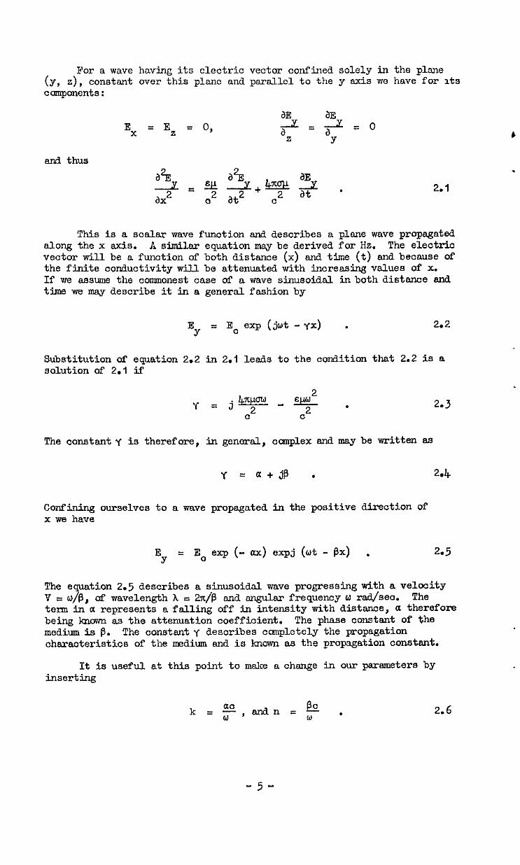
For a wave having its electric vector confiued solely in the plane (Y, 4, constant over this plane an3 parsllcl to the y axis we have for Its components:
and thus
2.1
This is a scalar wave function and describes a plane wave propagated along the x axis. A similar equation msy be derived for Hz. The electric vector will be a function of both distance (x) snd time (t) and because of the finite conductivity will be attenuated with incressing values of X. If me assume the commonest case of a wave sinusoidal in both distance and Ume we may describe it in a genersl fashion by
E = Y
E. exp (jwt -Yx) . 2.2
Substitution of equation 2.2 in 2.1 leads to the condition that 2.2 is a solution of 2.1 if
2 Ic?rcraw-E Y=j 2
C c2 *
The constant y is therefore, in general, complex and may be written &9
y=a+$ . 2.4
Confining ourselves to a wave propagated in the positive direction of x we have
E = Y
E. exp (- 0~) expj (wt - Px) . 2.5
The equation 2.5 describes a sinusoidal wave progressing with a velocity V = ~$3, of wavelength A = 27t,@ and angular frequency w raa/seo. The term in a represents a falling off in intensity with distance, a therefore being known as the attenuation coefficient. The phase constant of the medium is P. The constsntY describes cchnpletcly the propagation characteristics of the medium and is known as the propagation oonstsnt.
It is useful at this point to make a change in our parameters by inserting
& k=F,andnn=o ,
-5-
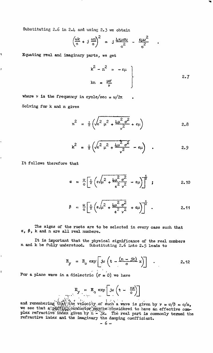
Substituting 2.6 in 2.4. and using 2.3 we obtain
EquatFng reel end imaginary parts, we get
k2 - n2 = -EF
kll=$ J
where u is the frequemy in cycle/set P w/a .
Solving for k end n gives
n2 = +xq+ +
It follows therefore that
_--
0 [(
, a = oi 2 EP2+ J- 4g - =CI
)T i
E ”
2.7
2.8
2.9
2.10
2.11
The signs of the roots are to be selected in every cese such that a, B, k end n are all real numbers.
It is important that the physical significance of the real numbers n end k be fully understood. Substituttig 2.6 into 2.5 leads to
E Y 2.12
For a plane wave in a dielectrio (a e O),we have
E _ -,_ .'. Y. = E. yz'[jy (t - !$)I
- \v. 3-J ".qX -I -t,,
and remenibering_~~~.$~~,h~ v$2c$ty70f ~.&;$a &me is g&en by v = w/P 5 c/n, we see that, ~~part,l.~-bonauotor'~~~be~~~.~~~red to have Sn effective cm- ,y-"r.-,F=4 plex refractive index giiren'by‘<'-*$i. The reel psrt is comonly tensed the refractive index anri the 5maginary the damping coefficient.
-6-
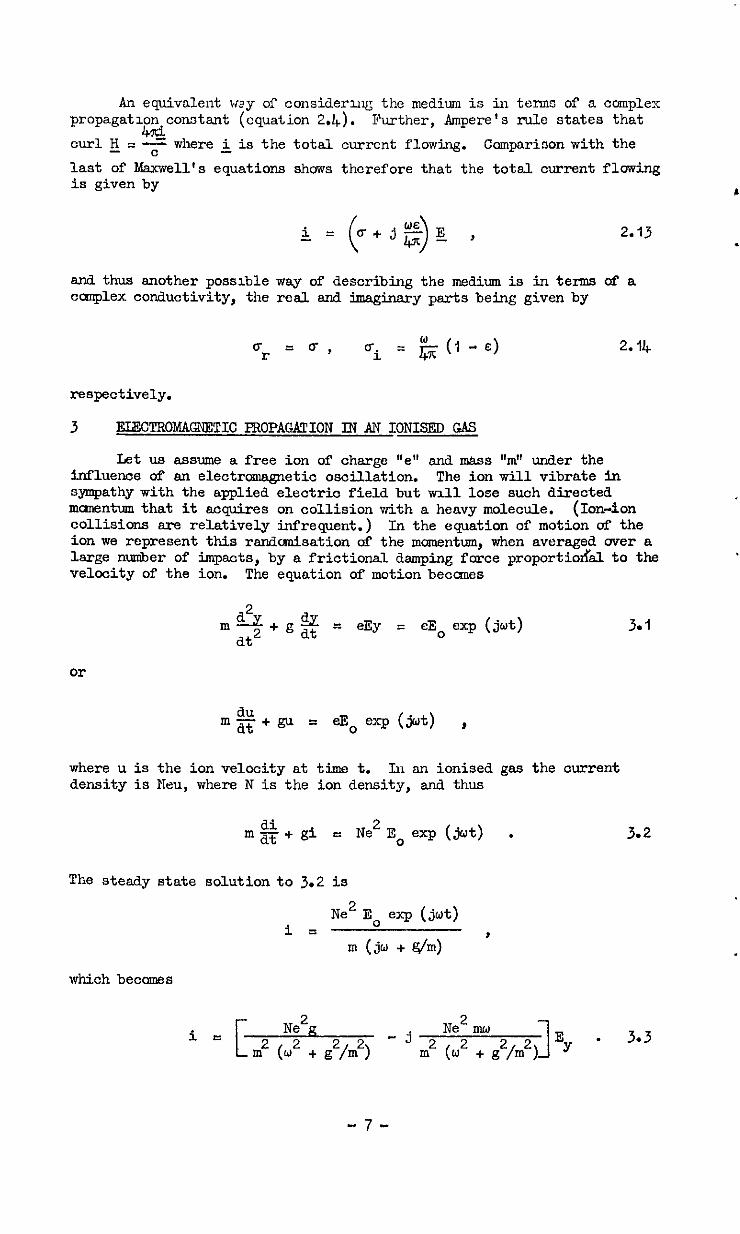
An equivalent way of considerug the medium is in terms of a complex propagatl~n condatd (equation 2.4).
curl&$
Further, Ampere's rule states that
where L is the total current flowing. Comparison with the
last of Maxwell's equations shows therefore that the total current fl0wing is given by L
i = (u+jf$)E ,
and thus another possible way of describing the medium is in terms of a ccmiplex conductivity, the real and imaginary parts being given by
respectively.
3 FJXXROMAC2LETIC PROP.4GA!l'ION IN AN IONISED GAS
Let us assume a free ion of charge "e" and mass W' under the influence of an electrcmagnetic oscillation. The ion will vibrate in sympathy with the applied electric field but vnll lose such directed mcmentum that it acquires on collision with a heavy molecule. (Ion-ion collisions sre relatively infrequent.) In the equation of motion of the ion we represent this rsndcmisation 0f the momentum, when averaged over a large number of impacts, by a frictional damping force proportiodd to the velocity of the ion. The equation of motion beccmes
= eEy = eEo exp (jut)
or
where u is the ion velocity at time t. ik an ionised gas the current density is Nau, where N is the ion density, and thus
di mE+ gi r Ne2 E. exp (jot) .
The steady state solution to 3.2 is
i 3 Ne2 EC exp (jut)
m(jw+g/m) '
which becomes
3.1
3.2
.
i e Ne'g -j
Ne2 mw
m2 b2 + g2/m2) m2 (w2 + g2/m2) 1 E y
. 3.3
-7-
1
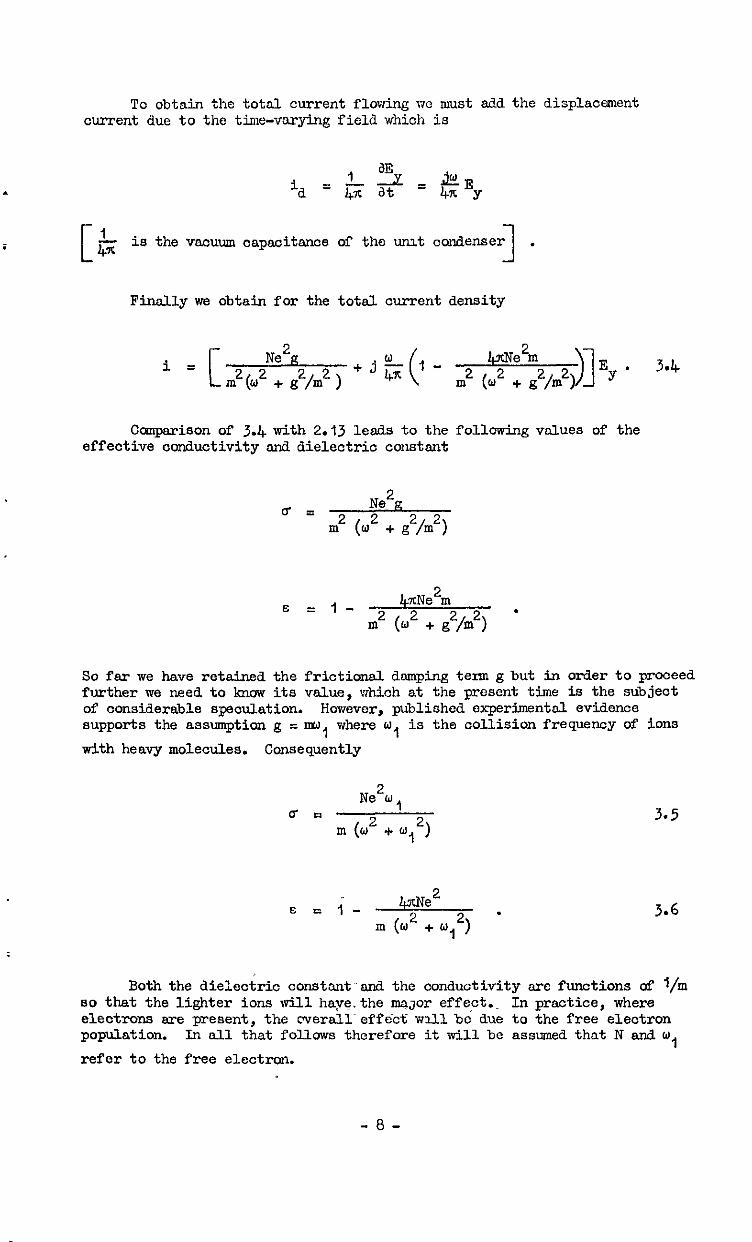
To obtain the total current flowing WC nmt add the displ.accment current due to the time-varying field which is
ia ‘3L,& = G at 4x EY
c 1 i 4x is the vacuum aapaoitsnoe of the urut condenser 1 . Finally ws obtain for the total current density
Ne2a 2
i = lp.Nem
In2 (02 + g2/m2 ) In2 (w2 + g2/m2) E . 3.4
y
Caaparison of 3.4 with 2.13 leads to the following values of the effective conductivity and dielectric constsnt
u = Ne2g
Ill2 (w2 + g2/m2)
E = l- 4xNe2m
In2 (w2 + g2/m2) -
So far we have retained the frioticnsl damping term g but in order to proceed further we need to know its value, which at the present time is the subject of considerable speculation. However, published experimental evidence supports the assumption g = MJ, where w, is the collision frequency of ions
with heavy molecules. Consequently
u = Ne2wi
m (02 + w
2 E = l- Me
m (02 + y2) .
3.5
3.6
Both the die:cc&io constant-and the conductivity arc functions of l/m so that the lighter ions will hnys.the maJor effect.~ In practice, where electrons are present, the overalleff6ct will be due to the free electron population. In all that follows therefore it will be assumed that N and w,
refer to the free electron.
-8-
Substituting into 2.8 snd 2.9 and assuming g = 1, as is nearly slways the onse for a gas, we obtnin
n2 &t
2 s 3 I - 4x&3* 47cNe2 &cne2 \ a m(w2 + Wi2) 1 [ + m(w2 + y2) w1 2+ l- CT 1 [ m(o2 + w, * / ) 1 3.7
k2 1 2 + [ lpxe2 * 2
m(w2 + w,2) ,- 4xNe*
w
1 *- 1 m(w2 + y2) I> .
The above equations may be used to describe cmpletely the propsgation of radio wave* within an ionised gss in terms of electron density, electron collision frequency and angular radio frequency.
The physical picture of electrons vibrating in sympnthy with the electric field and subsequent collisions randanieing the manentum demands two assumptions. First, that the strength of the electromagnetic field is such that it does not upset the collision frequency of the electrons and secondly, that several oscillations of the electron may occur slang one free path. The former assmption is generslly valid, but the latter is not and together with the assumption g = nw, involves sn erroneous nvernging of
electron velocities. The energy distribution of the electron must be taken into account. This has been done by Margenau2.
For Msxwellisn distribution of electron velocities Margenau derives
ur = !i ti K (x) 3 (-)% 2 1
3.8
Where h' is the m.?an free path of the electrons, snd
K2(x,) I I - x, - x12 exp (x,) Ei(-x,)
3.9
K3,2(x,) = (4 - x,),3 + .xp =xp (x,) (1 - erf (x,'i)) ,
-P-
Ei snd erf represent the exponential integral and the error function respectively.
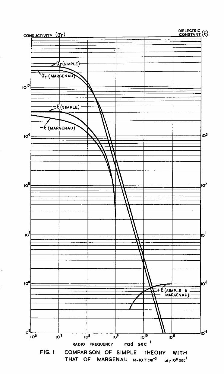
In Fig.1 arc plotted the concluctivlty sxd diclectrx constant, as determined by the simple theory and Margcnccu's, sgainst w for o, P IO8 sea -1
N I iOiO om-3. ,
It can be seen that there is little difference between the two when considering the eleotrcwagnetic properties of rocket exhausts. The sFmple theory is adequate snd easier to apply.
Before leaving the oanplete theory of Msrgenau there are two special cases of interest:
frequeki is Where the ionised medium is at high pressure and the radio
low . Under this condition we have x, + 0 end
Lim% = 1, G IAm K3,2 = z .
x +o 1 x -+o
1
Therefore
Substituting the value of h' from gas kinetic theory
ur (Msrg) = $- Efz, ml
ui (Mnrg) = $ * .
mJ1
The ssme condition on the simple theory is described by a2 << w whence
ur (simp) = d , mJ1
ui (simp) = *
mJl
and therefore
- 10 -
(b) At low gas pressures and high rarlio frequencies, we have x, + m and thus
It follows that
Qz-' ui (Mm-g) = $+ .
On the simple theory this oondition is described by w,* << u2 andthus
4 A!EENUATION Ei A PARTIAL CONDUCTOR
Let the peak powers at two points x,, x2 on the x axis be P,, P2
respectively. From 2.5 m may write
P, = PO =P (-29)
P2 = PO exp (-*ax*)
where PO is the power at sme arbitrary point x = 0.
The attenuation experienced over this interval is by definiticol
p2 IJ = 'O logjo ';;
exp (-%I = *o loqo expm c3B
= 20 loglo exp (ax, - ax2) dB .
- 11 -
Putting x2 - x, = I we obtain as the nttenua.tion per unit path length
6 2Oa = -2,joj=-
-- 20 kd 2.303 0
m Q3;l
with c = 2.998 x 10 IO -1 cm se*
6 = +.897.10'" -1
kwm cm 4.1
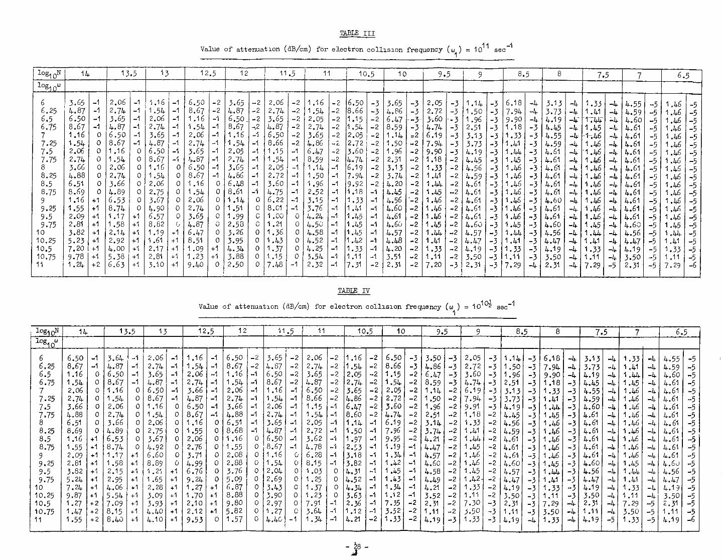
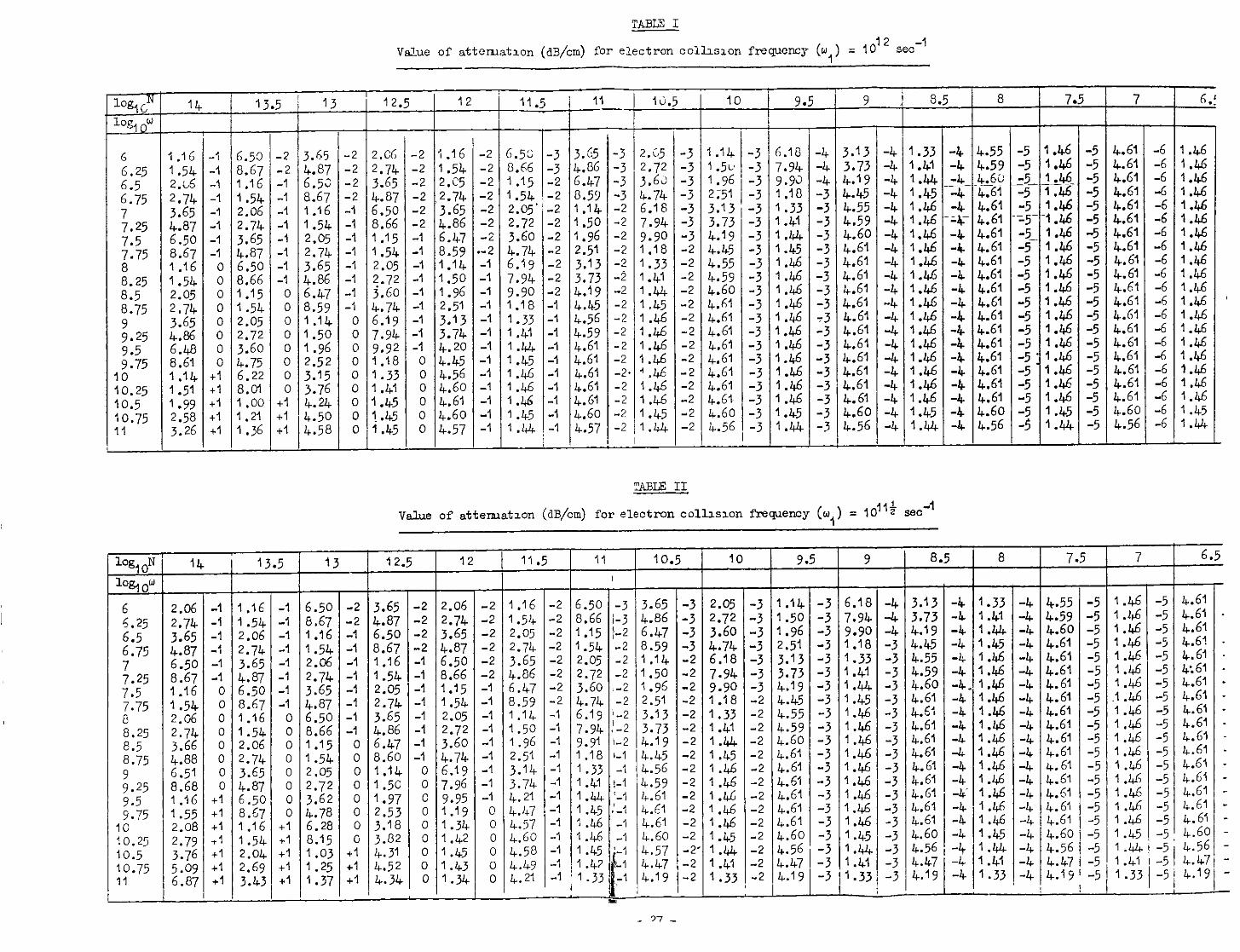
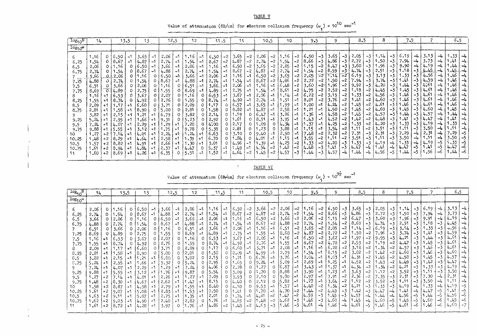
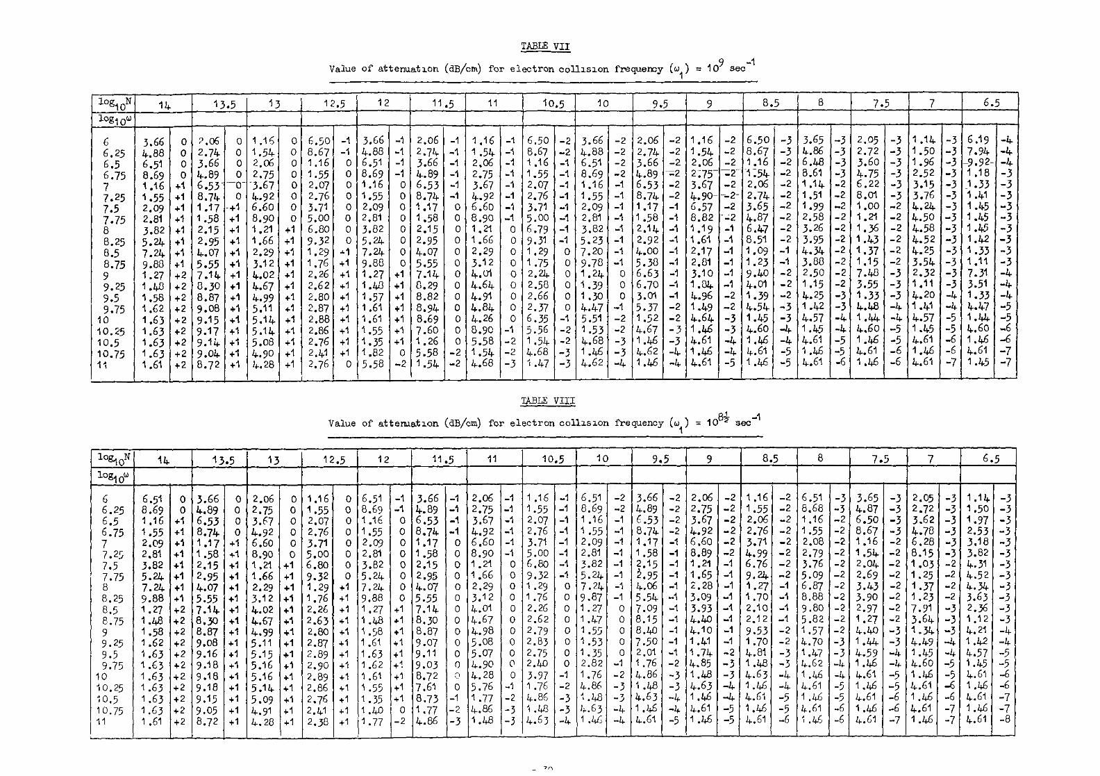
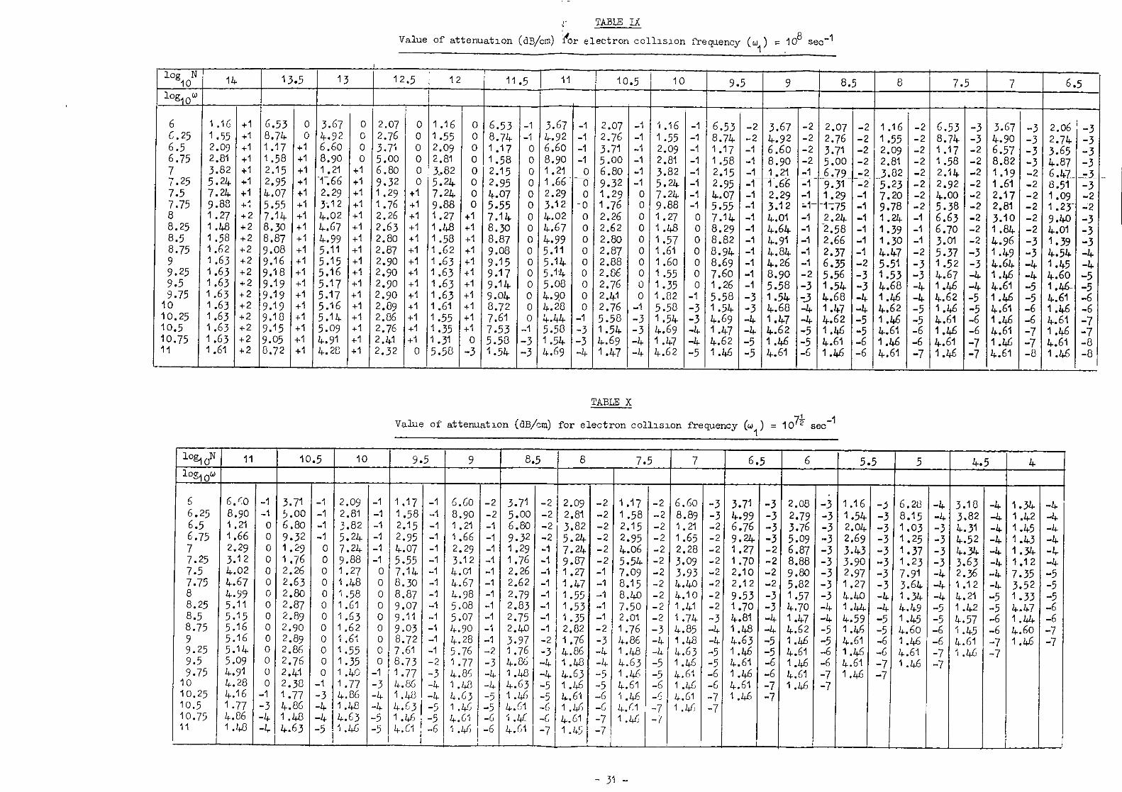
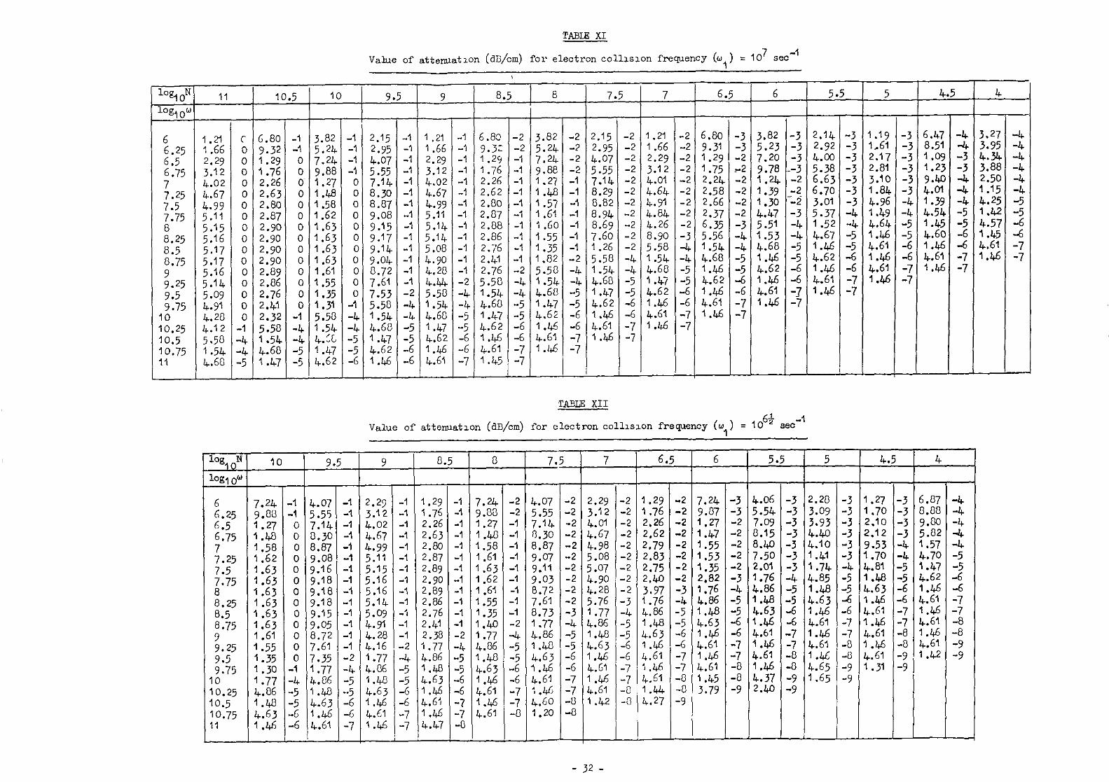
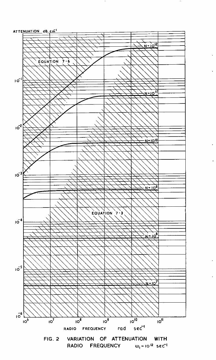
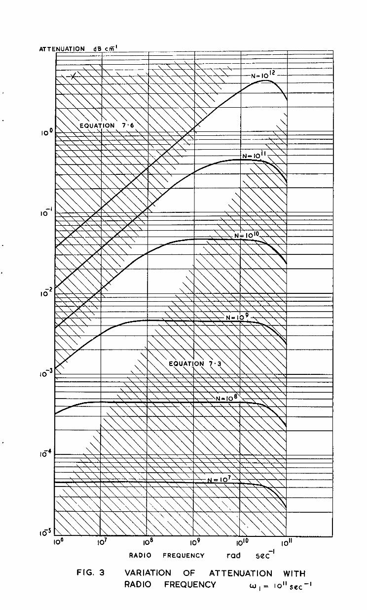
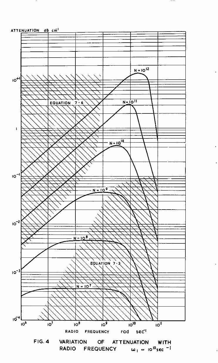
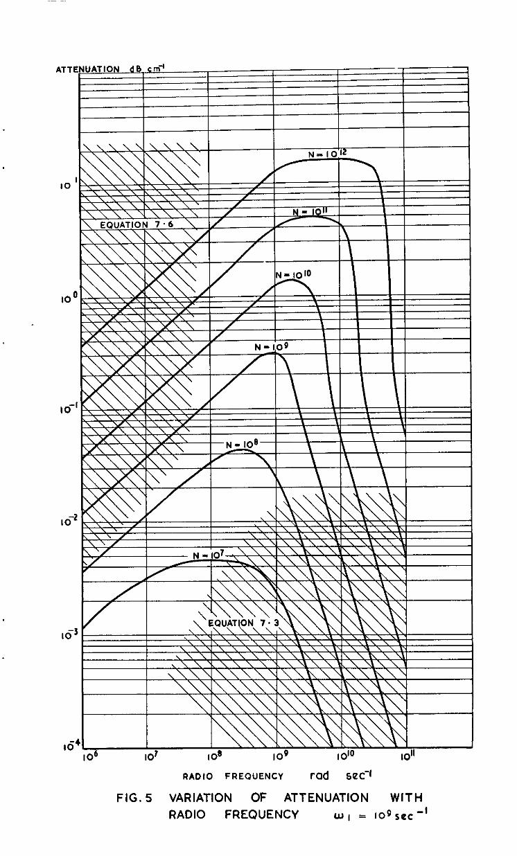
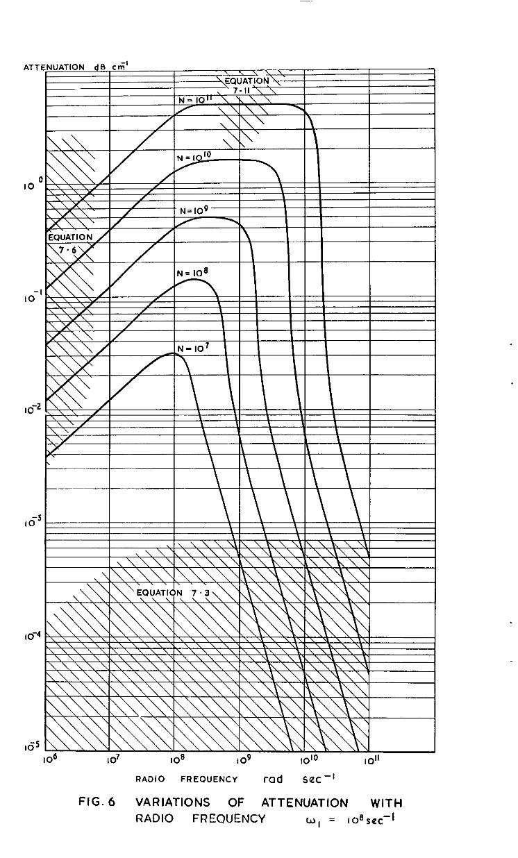
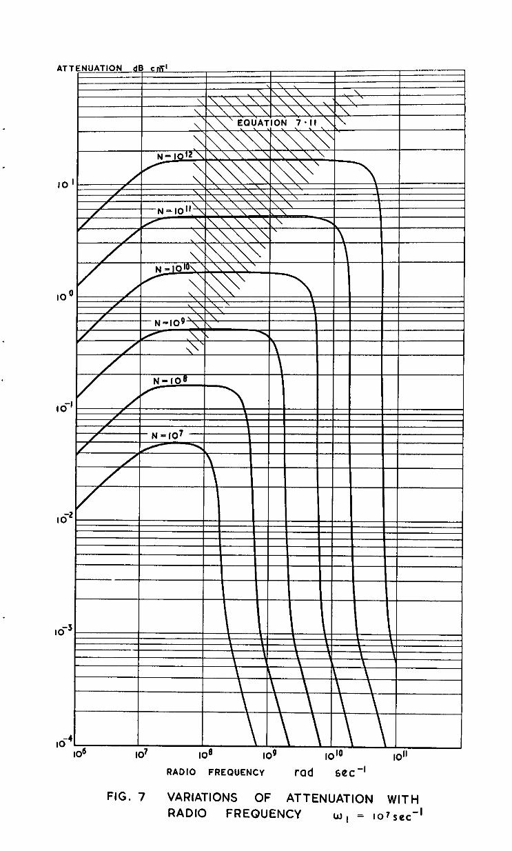
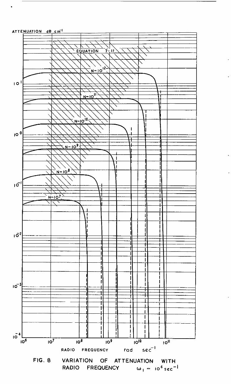
In Tables I to XIII values of 6, as cunputed on the simple theory, are tabulated against the variable o for the two parameters N and w,. The 8m information is presented graphically in Fig. Z-8.
5 PHASE SHIFT IN A PARTIAL CONDUCTOR
We have (equation 2.5)
E Y
= E. exp (4x) exy, (j(wt - WI -
\~e may write frm equation 2.6
where n is the refractive index of the medium given by 3.7 for an ionised
g=. The phase constant for free space is p, = $ and thus the phase shift
experienced by the electromagnetic disturbance with respect to the wave in free apace is
*0 - p = z (1 - n) rsd cm-' . 5.1
When n < I the phase of the wave in the medium is retarded; when n > 1 it is advanced with respect to the wave in free space.
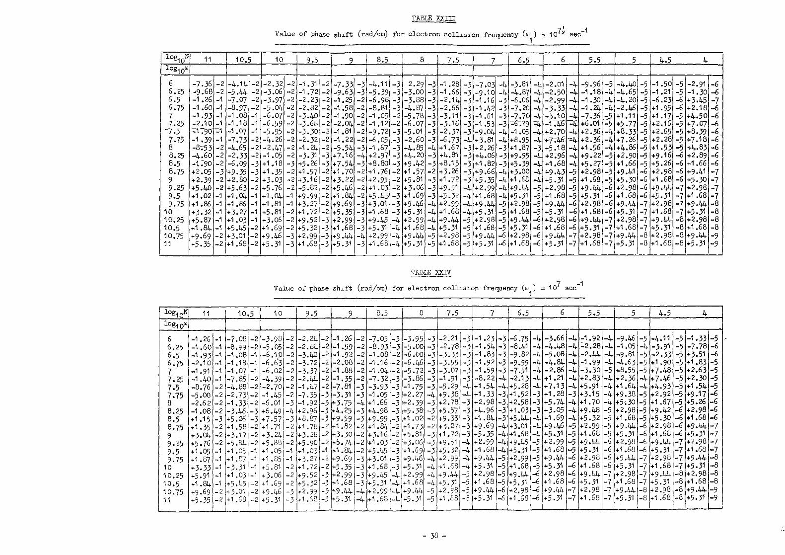
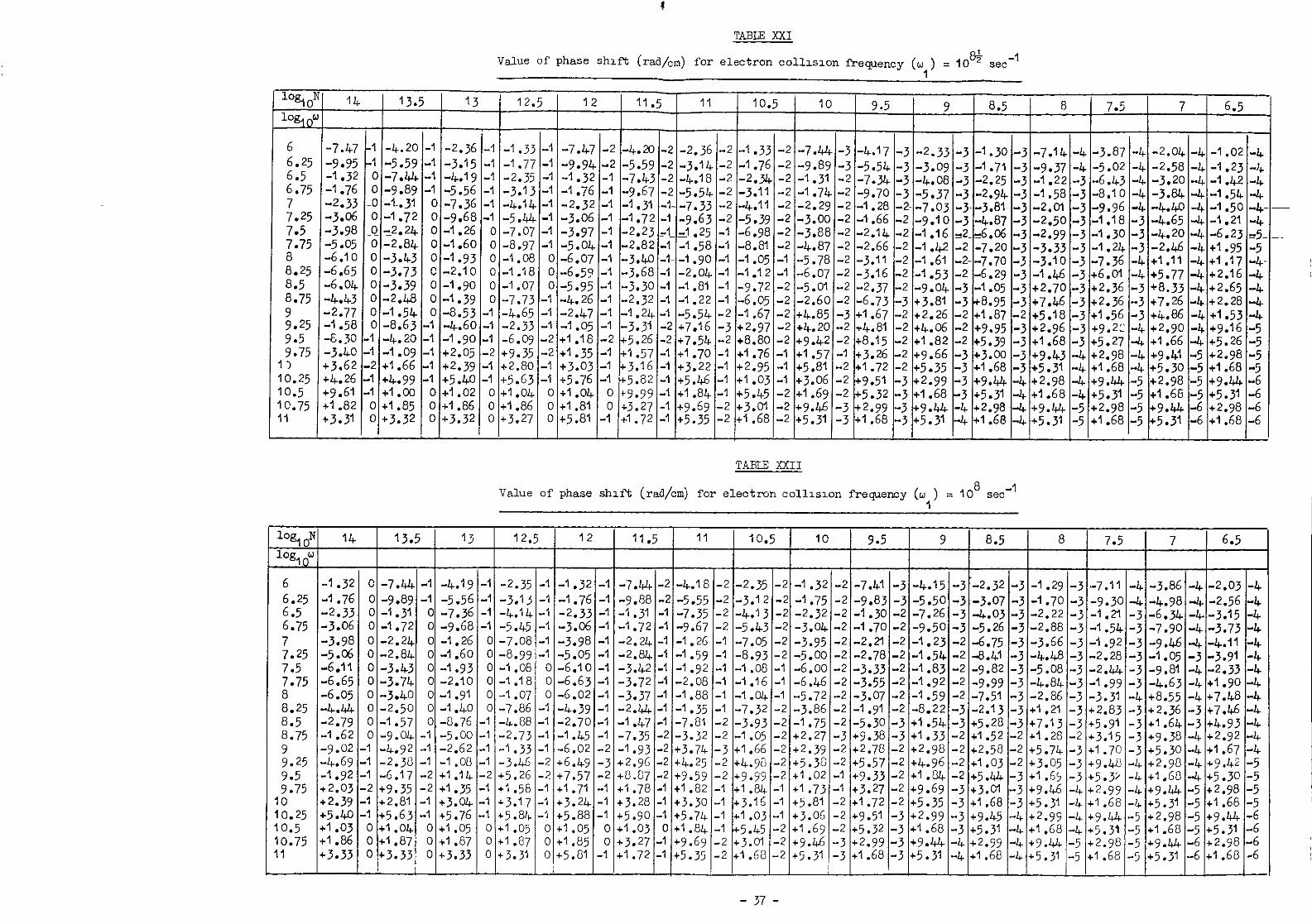
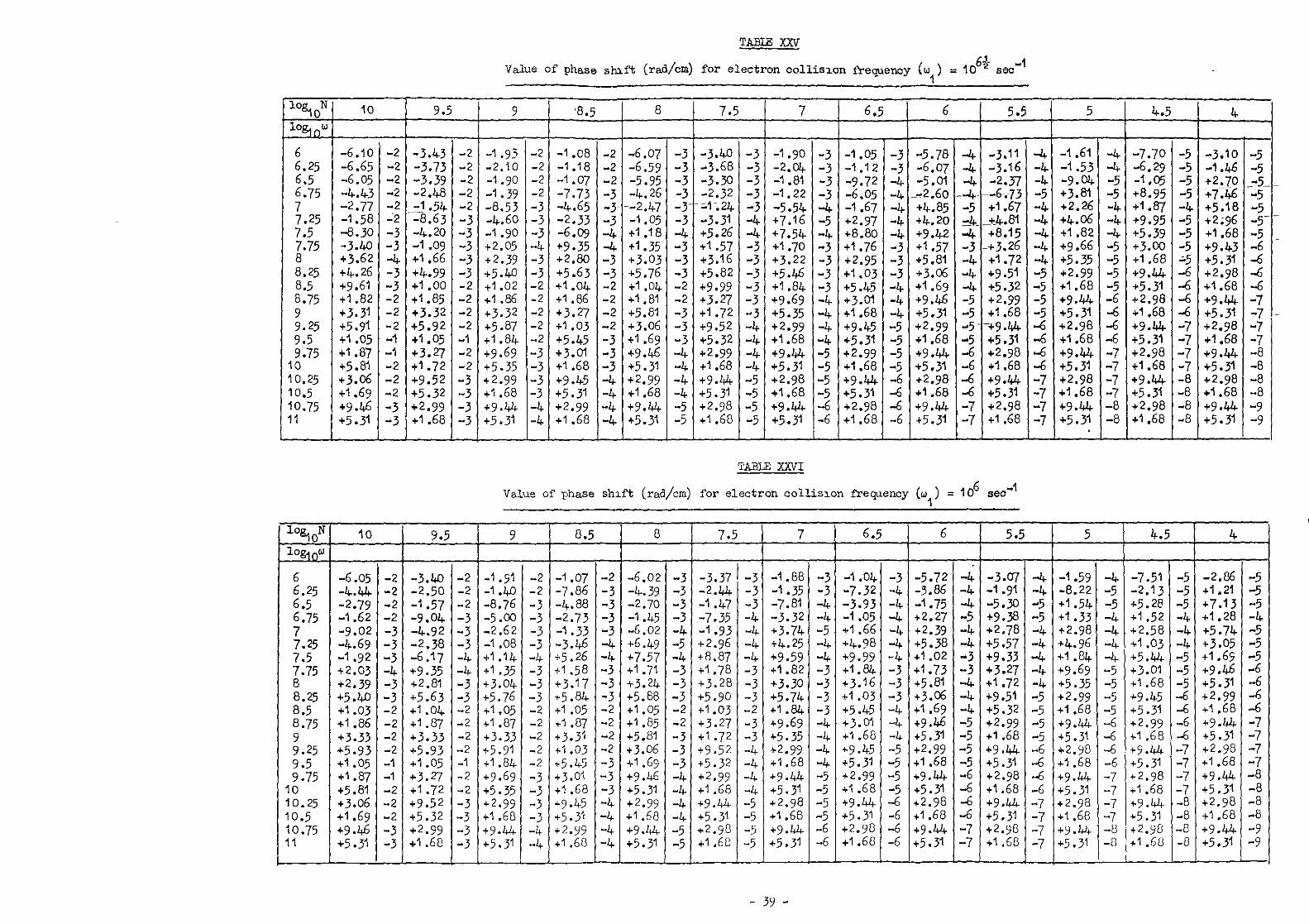
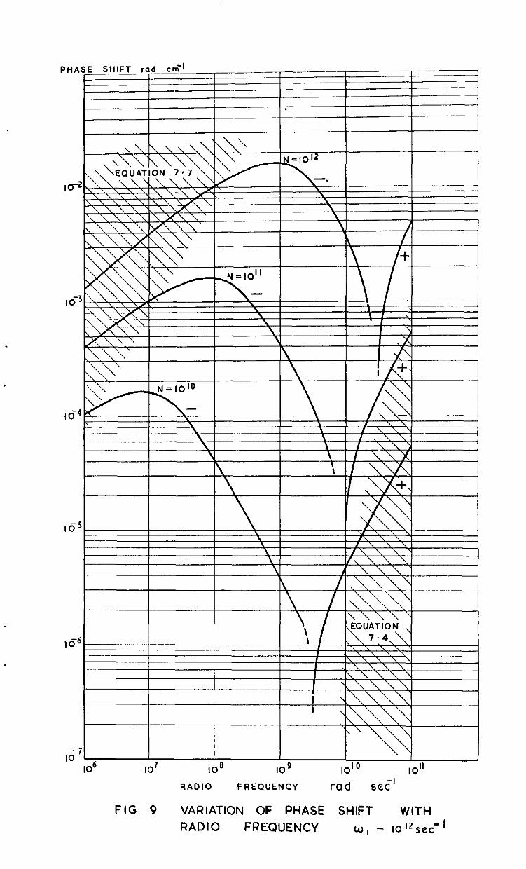
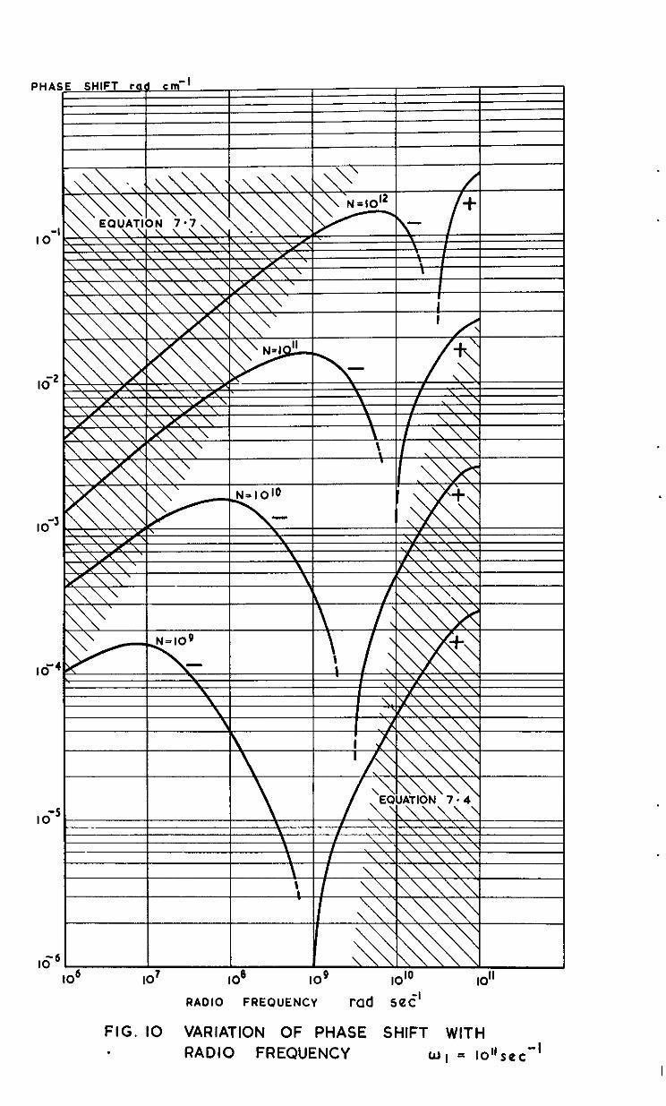
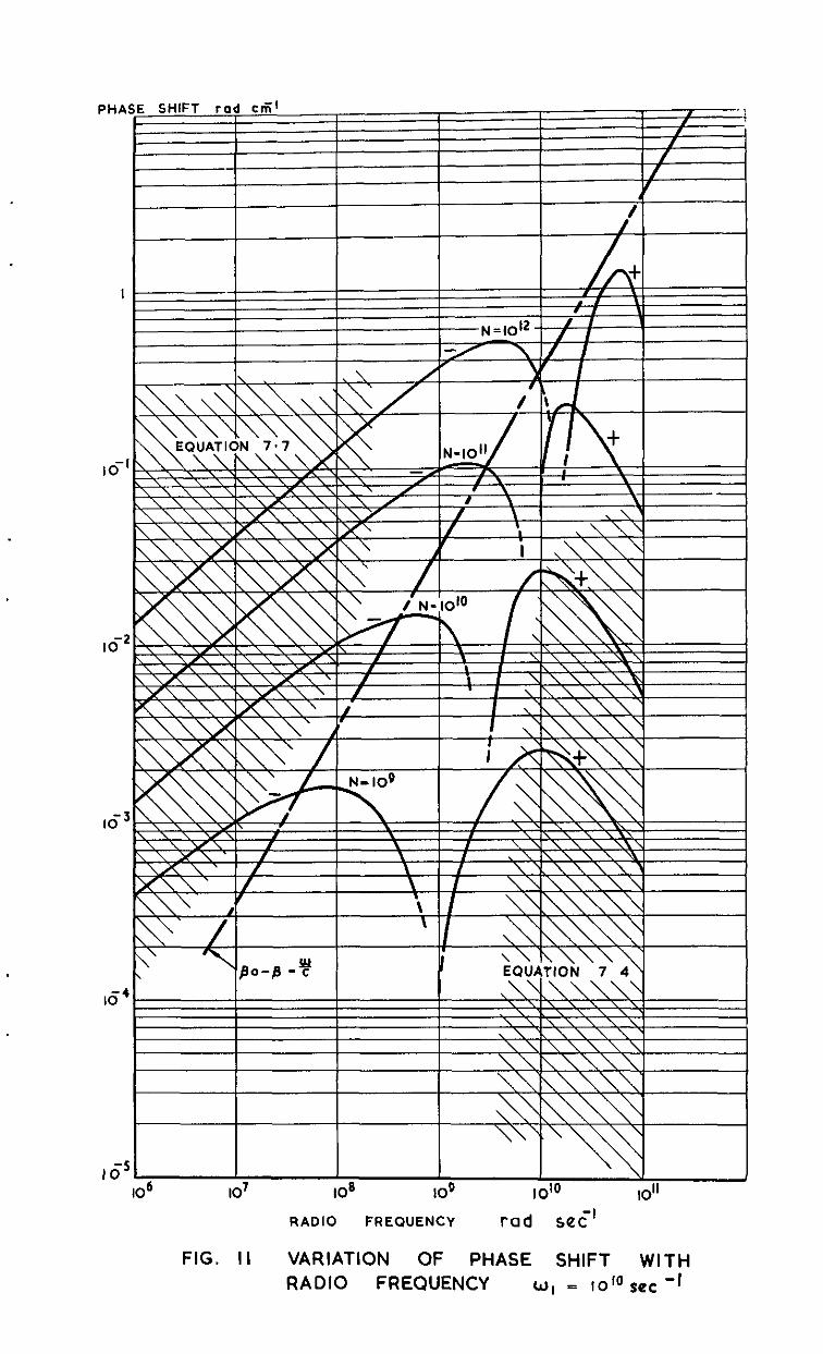
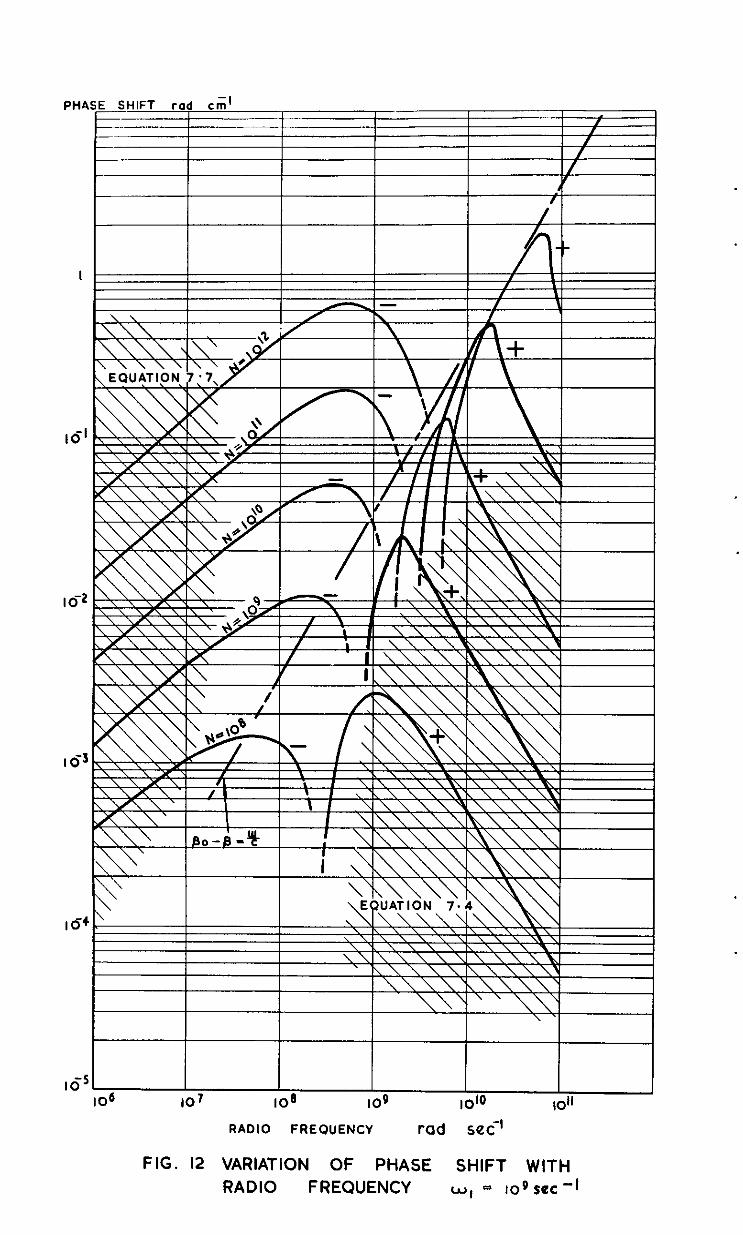
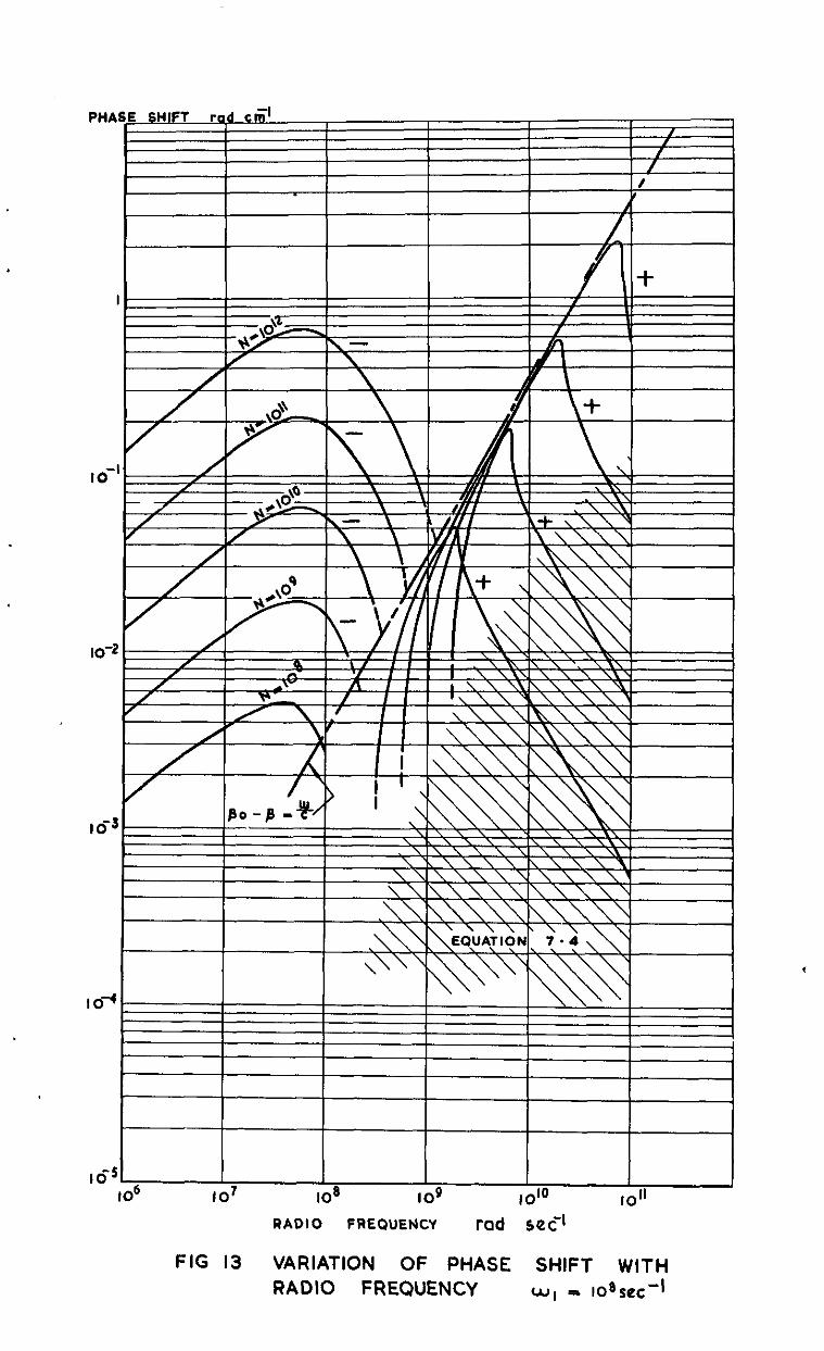
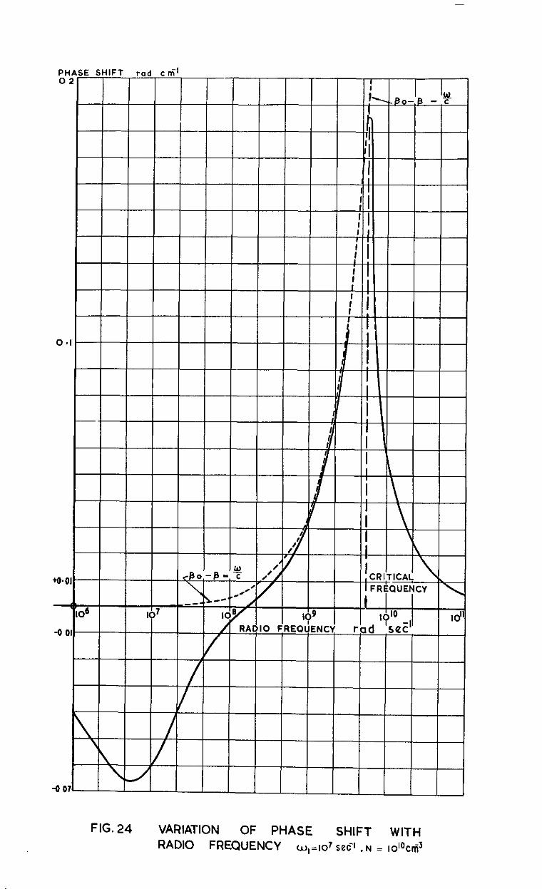
vsluesofi3 -P, computed by the use of equations 3.7 snd 5.1,az.w tabulated with th$ variable w ad paremeters N and w, in Tables XIV - XXVI. The ~33110 inf'ormation is presented graphically in Fig. 9 -j5. For convenience they are plotted on a logarithmic scele and the curves therefore appear dis- continuous; this however is not the case, ss can be seen in Fig.24 where BO
- I3 is plotted on n line'er scale.
6 REFTXCTION AT NORM.% INCIDENCE TO THE B!XJXDARY OF APARTIAL CONDUCTOR
The detemGnation of the voltage reflection coefficient normal to the boundary of an ionised medium demands a !mowledge of the relative magnitudes of the magnetic and electric vectors within the medium.
- 12 -
For a plane wave we may write Maxwell's second equation as
6.1
We shall assunm a solution to this equation to be some function of (X - vt) v being the phase velocity, in the medium. Therefore
E Y = f(X"vt) .
Fran the wave equation of seotion 2 (equation 2.1) we launv that Hz will
have a simile.r dependence on x and t. Therefore let
HE = af(x-vt+b) ,
where a edi b are constants yet to be determined.
The above is a solution of 6.1 only 53'
b =O
0
a=Clv * 6.2
Let us for the moment consider a dielectric medium (a = 0) so that the wave equation 2.1 becomes
a% Y=
a% 4ti.;y.
ax2 o2 at2
In this ease the velocity of propagation of the wave in the medium is given by
end thus 6.2 becomes
a = 6 '
and we inmediately have
6.3
- 13 -
As shown previously (section 2) a partial conductor may be considered to have a complex refractive index (n - jk). Therefore, in order to put 6.3 into a form imnediately applicable to a partiel conduotor, the refractive Max =
Therefore
, c v
= q = n-jk
H za n-j& E
Y P 6.4
Having derived 6.4 we msy now prooeed.
Consider an electrcmagnetic wave incident nornmlly on a vncuum/partiel conductor interface of infinite extent. The boundary condition is the ccmmon one of tangential E and H continuous across the interface. Remember- ing that the reflected wave reverses direction of travel and that therefore either Er or H, must undergo phase reversal, we have
E i
+Er = Et
Hi- Hr = Ht
*i i =H
E rH r r
H n-Jk* t" P t '
(the subscripts "i" refers to the incident wave, "t" to the transmitted wave and "9' to the reflected wave) and thus
E. -Er n - jk E; +Er = I-I '
The voltsge reflection coefficient nwy be defined by
Therefore
6.5
The voltage refleotion coefficient is therefore complex, indicating a phase change on reflection. The magnitude of the coeffioient is given by
612 2 2
=RA-) +k . (p + n)' + k2
6.6
Ae before, p c I and thus findly
2 2 R
= (:
-n +k
+ n)2 + k2 . 6.7
The phase change cm reflection may be determined frm 6.5 as follows:
where
tan e2 k =i= l
We my therefore write
r = A exp (j8)
where A is the modulus and 8 the argument of the cmplex mm&err. We have
'r =rE i = AEi exp (je) . \
If, as we have so far assumed, Ei maybe described by
Ei = E. exp (Jot) ,
then % = dEo exp (jut + 0) -
Thus the phase change is given by
e = e, + e2 p tan --I 2clk radian . p2 - n2 - k2
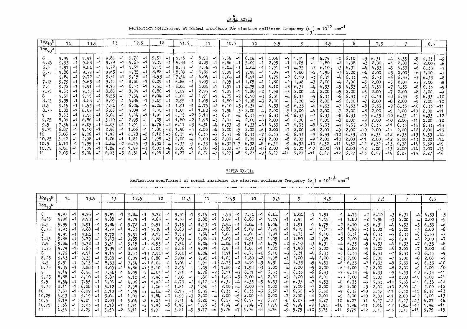
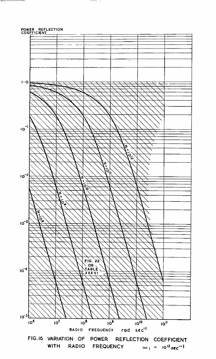
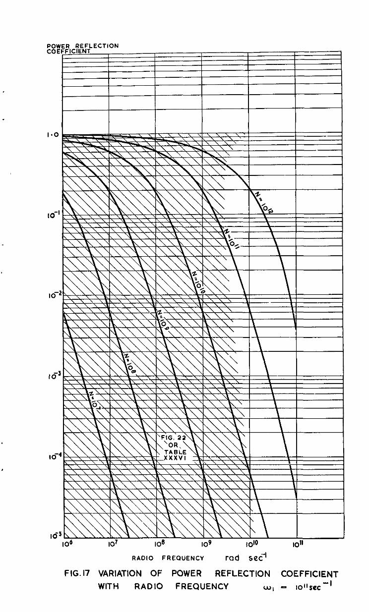
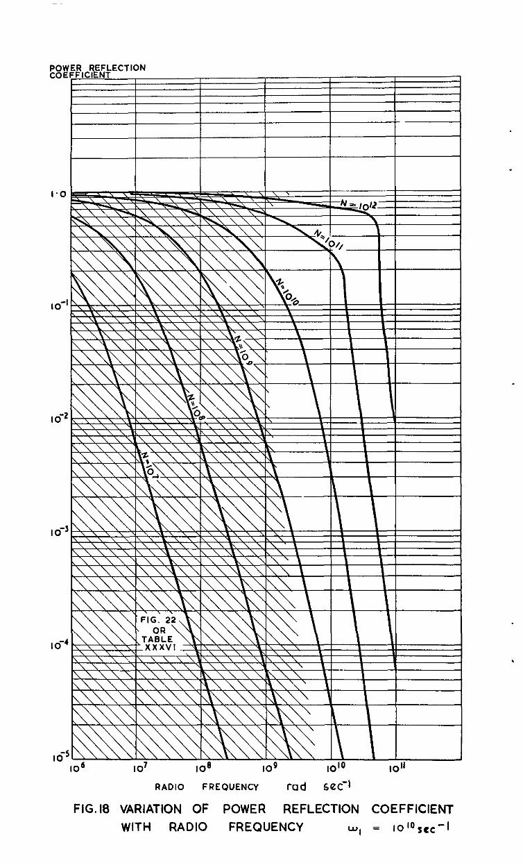
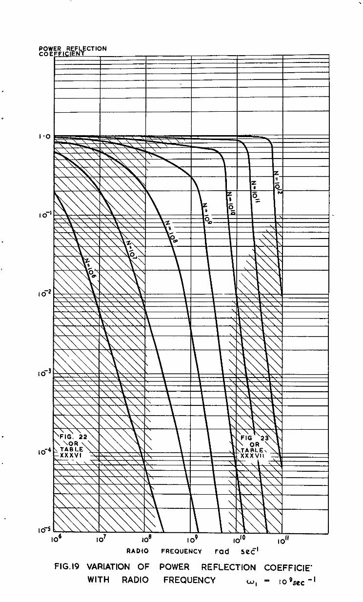
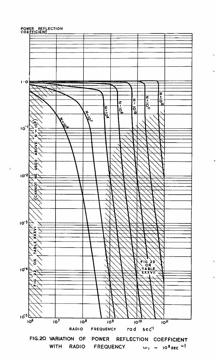
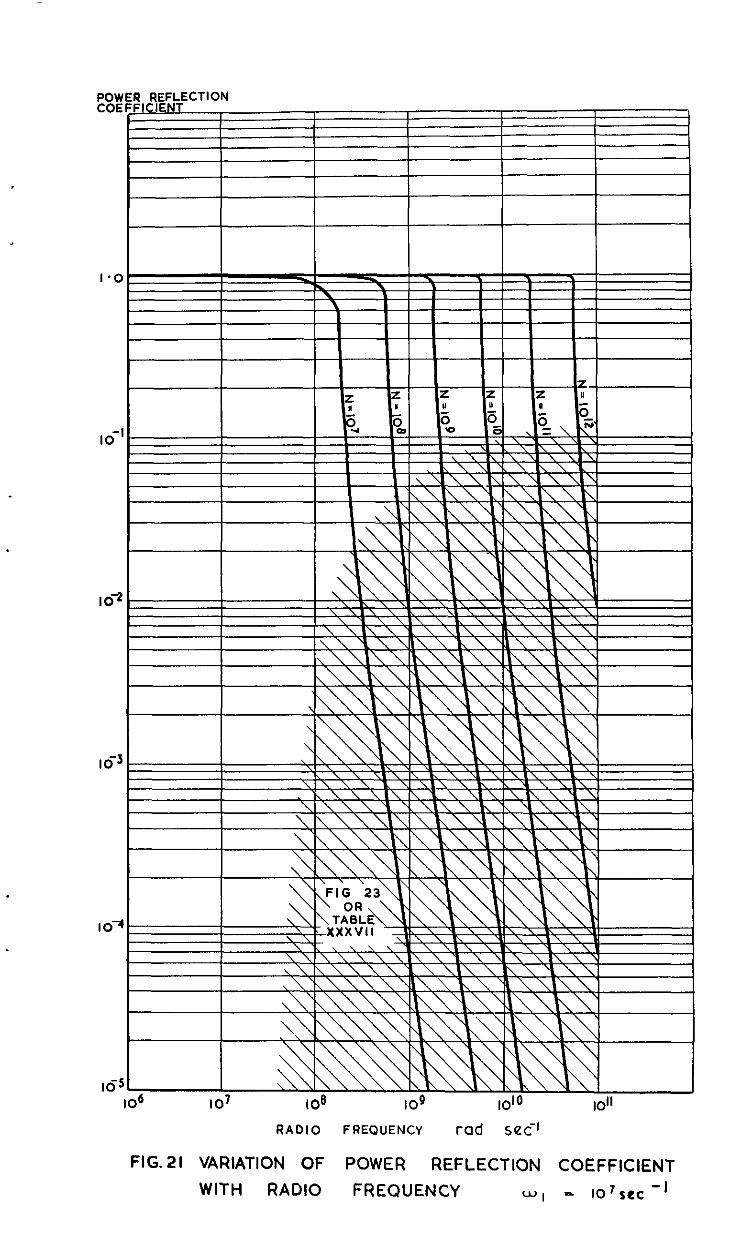
The per reflection coeffioient R is tabulated in Tables XXVI - XXXV and graphically presented in Fig. 16-21 for a~aaticel range of values in
5' oat-law I'
- 15 -
7 APPROXIMATIONS TO TIE SIMPLE TIIEORY FOR A GASEOUS MEDIUM
7.1 High values of w,
The genordl complication of equations 3.7 makes it dFTficult to , detenxine kmediately the effect of changes in the variable N, w and 0, on
the find result. This difficulty may be overcome by a consideration of the relative magnitudes of the conduction current and displacement current. Such a course is doubly useful in allavkg the derivation of a good approxi- mation and in presenting a clear physical picture of the controlling pro- cemes.
The total current density in the medium may be written as
The ratio of the aoniluction current to the total displacement current is
therefore described by the term EW 4Ez=6 EV . Reference to equations 2.10 and
2.11 shows that it is just this ratio which predominantly controls the values of a and P, and thus the overdl properties of the medium. There are two cases of interest. First, where the displacement current predti-
zo- n&es, described by TV << 1, and fieoondly where the conduction current
prcdminates, described by 5 >> 1.
This arises when the medium is a poor conductor or when it is n good conductor with a high applied radio frequency. We hnve from equation 2.10, with I-I r 1,
Expanding by means of.the binmid theorem,
There are two solutions;
and
a2 = 3-j(-2c -9-f ,
according to which sign o$~t..e~~~~q&re root is to be taken. The choice is detemined b;y the faot that a is definki as being real and positive.
- 16 -
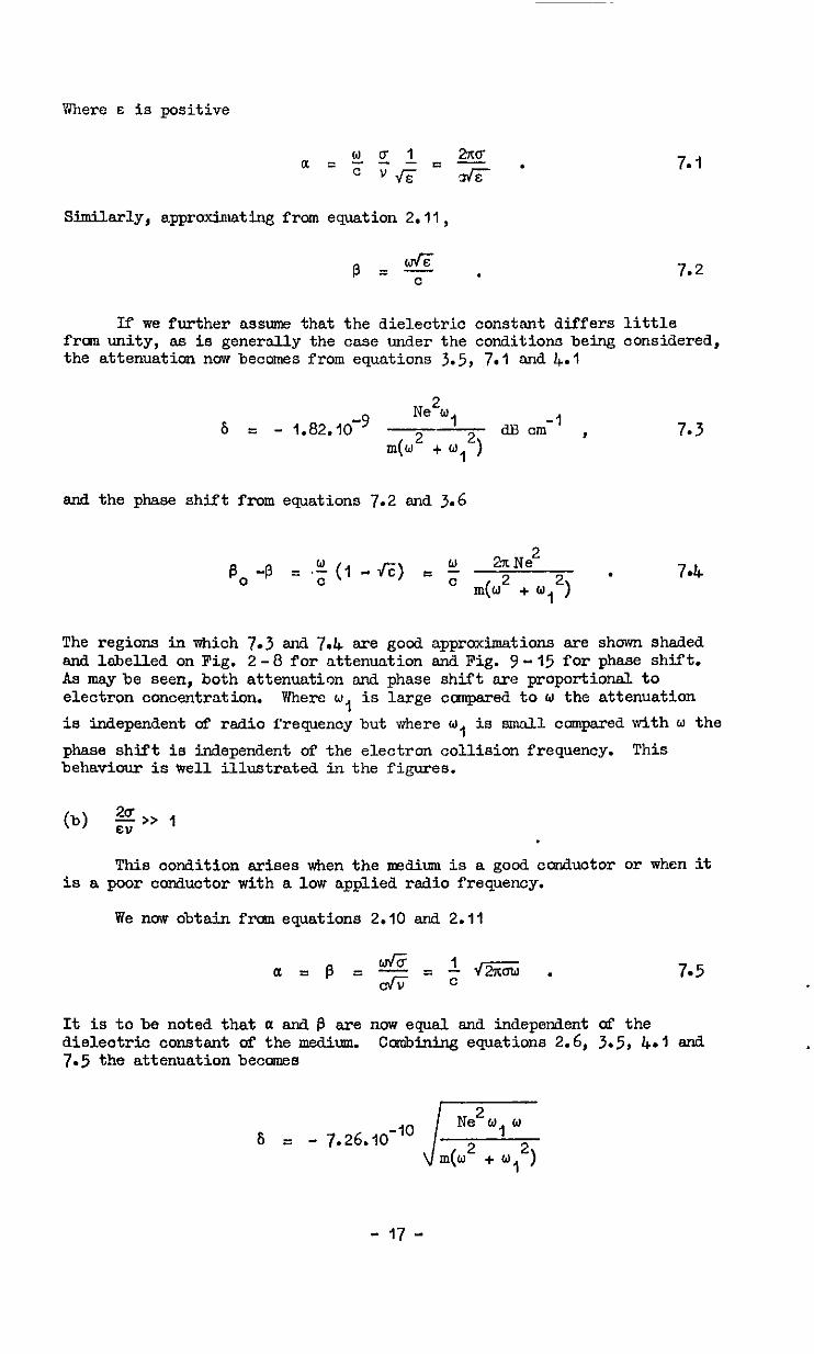
Where s is positive
7. I
Similarly, approxi.matinS from equation 2.11,
p=+ . 7.2
If we further assume that the dielectric constant differs little frcm unity, as is generally the case under the conditions being considered, the attenuatim now becomes from equations 3.5, 7.1 and. 4.1
6 - 1.82.10-9 Ne2w, -1 ZS --&3cm ,
m(w2 + y2) 7.3
and the phase shift from equations 7.2 and 3.6
.E, -p = .t (I - 4%) r ; 2XNe2
l&J2 + 0, 2, - 7.4
The regions in which 7.3 and 7.4 are good approximations are shown shaded and labelled on Fig. 2-S for attenuation and Fig. Y-15 for phase shift. As maybe seen, both attenuation and phase shift are proportional to electron concentration. Where w, is large canpared to w the attenuation
is independent of radio frequency but where w, is small compared dth w the
phase shift is independent of the electron collision frequency. This behaviour is tvell illustrated in the figures.
This condition arises when the nw.Yiium is a good conductor or when it is a poor conductor with a low applied radio frequency.
We now obtain fraan equations 2.10 and 2.11
7.5
It is to be noted that a snd B are now equal. and independent of the dielectric constant of the medium. ccmbining equations 2.6, 3.5, 4.1 and 7.5 the attenuation becomes
6 = - 7.26. IO-" J Ne2w, w
m(w2 + 0, 2,
- j7 -
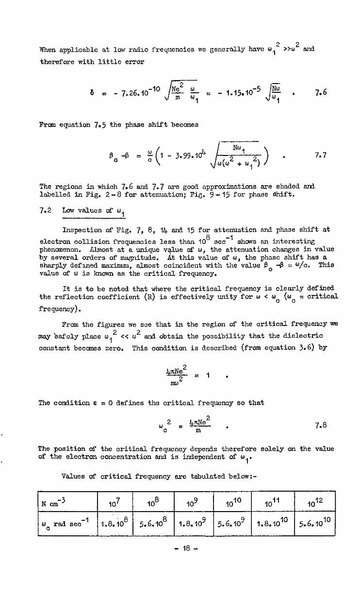
When applicable at low radio frequencies we gene~~ally have u,~ >W2 and
therefore with little error
Frcsn equation 7.5 the phase shift becomes
B, -B = t 1 - 3.99.ldc ( J$N:lw;) > * 7*7
The regions in which 7.6 and 7.7 ore good approximations exe shaded sn3 labelled in Fig. 2-O for attenuation; Fig. Y-15 for phase shift.
7.2 Low values of w,
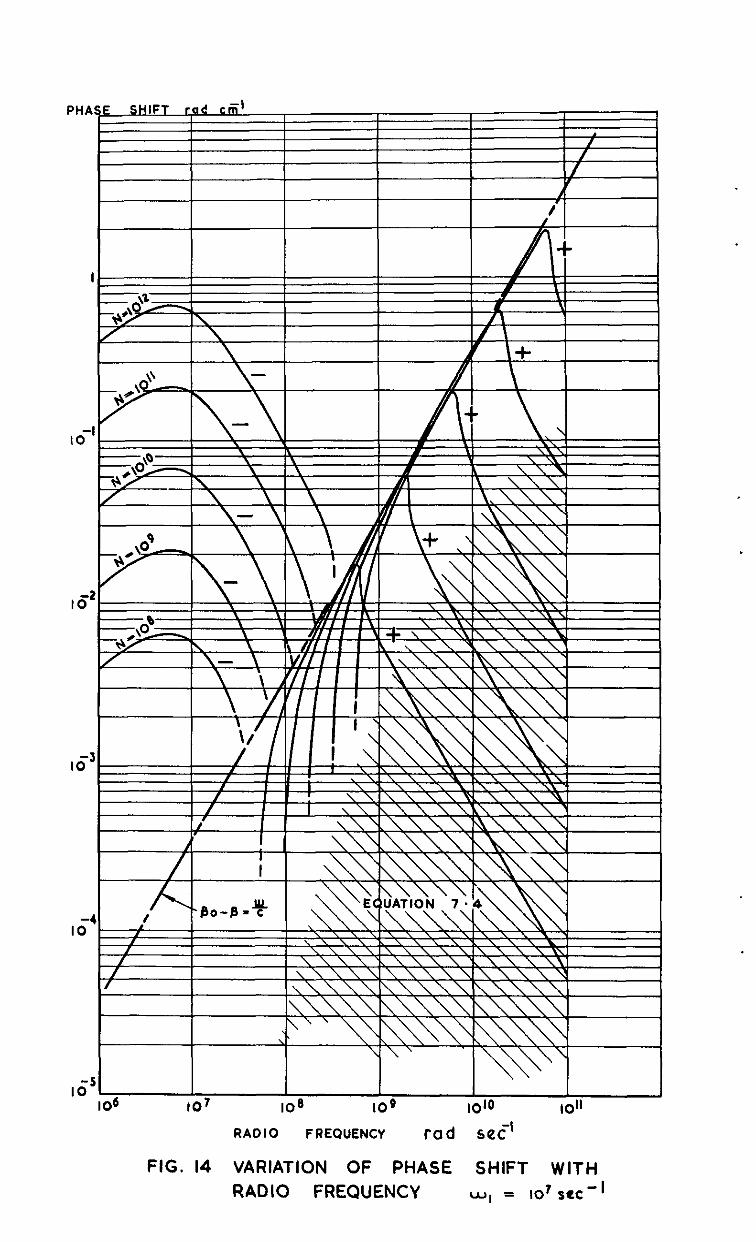
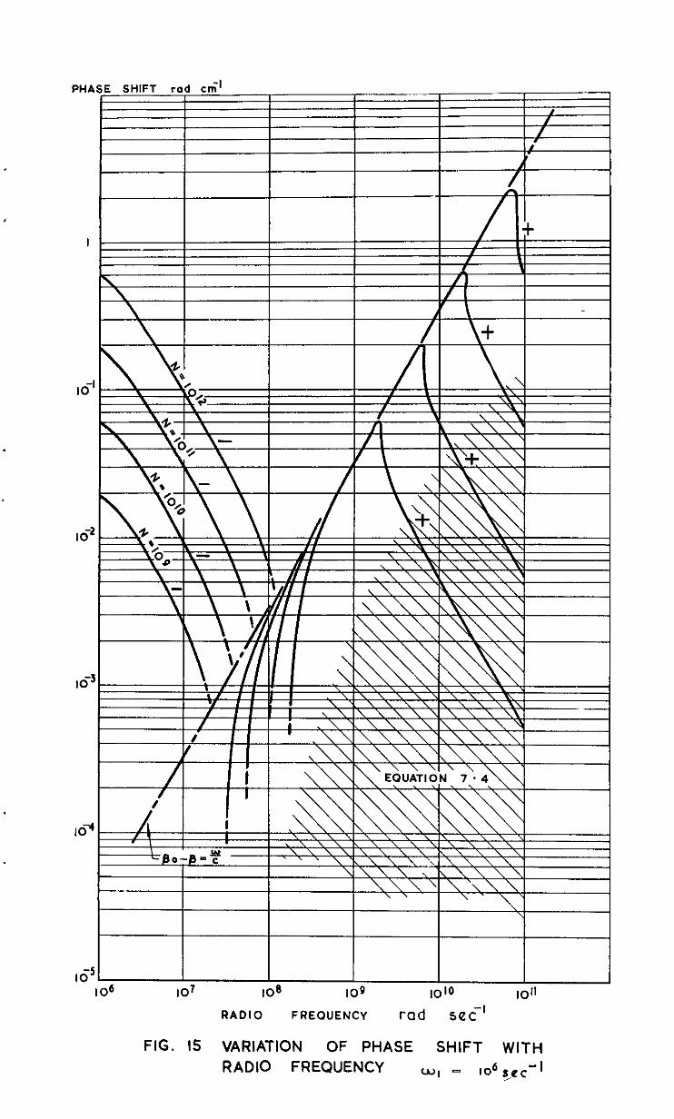
Inspection of Fig. 7, 8, 14 end 15 for attenuation and phase shift at
electron collision frequencies less than IO8 seo -1 shows M intereoting phenomenon. Almost at a unique v+lue of o, the attenuation changes in value by several orders of magnitude. At this value of o, the phase shift has a sharply defined meximum almost coincident with the value PO -@ = w/c. This vslue of w is hewn as ihe critical frequency.
It is to be noted that where the critical frequency is clenrly defined the reflection coefficient (R) is effectively unity for w < wc (w. = critical.
frequency).
From the figures we see that in the region of the critical frequency WB
may 'ssfcly place w,~ << w2 and obtain the possibility that the dielectric
constant beccanes zero. This condition is described (from equation 3.6) by
4$=, .
The condition E = 0 defines the critical frequency so that
The position of the critical frequency depends therefore solely on the value of the electron concentration and is independent of w,.
Values of critical frequency are tsbulated below:-
N C.IU-~ to7 IO8 IO9 IO'O IO" lOI
wc rat3 set -I .~8
1.8.10 5.6.108 1.8.10y 5.6.10' 1.8.1010 5.6.10"
- 18 -
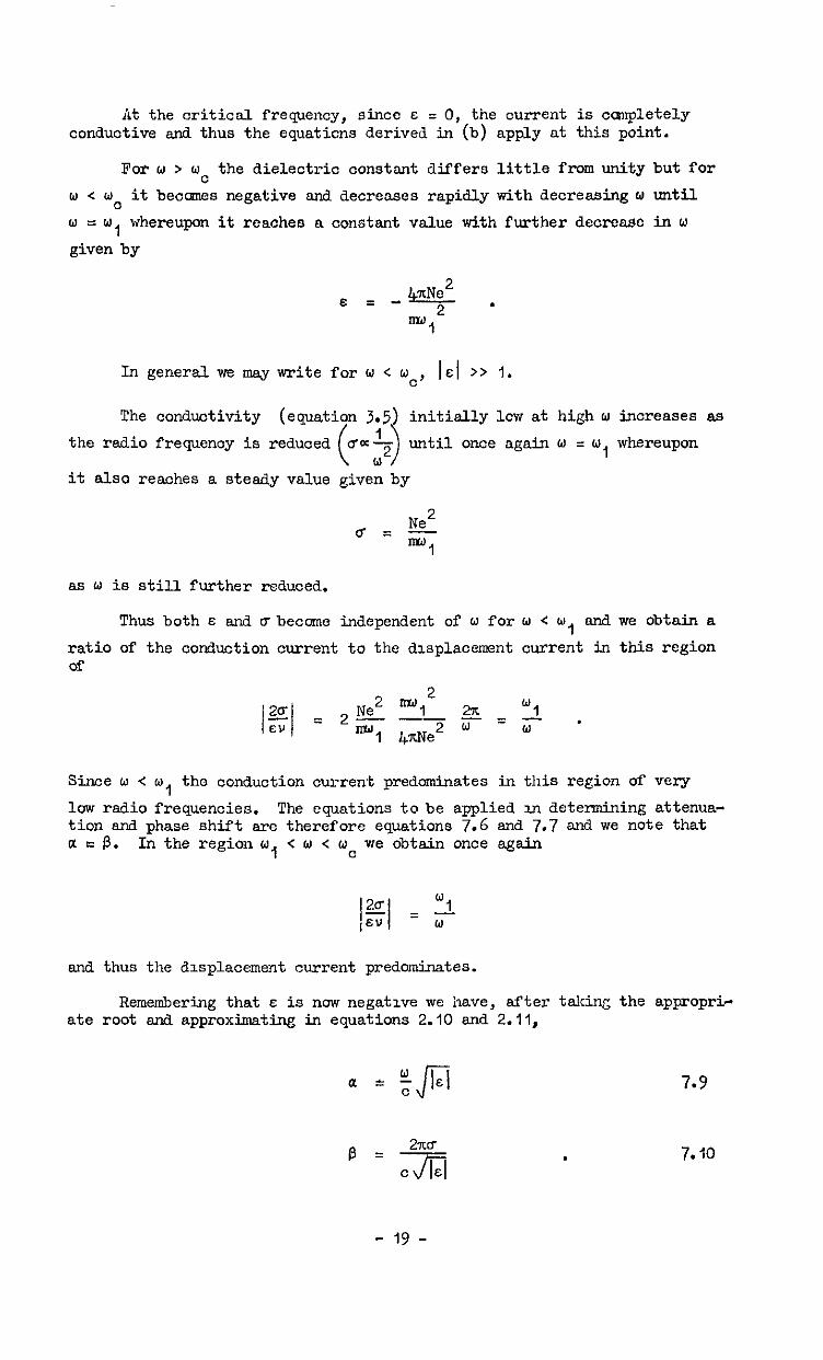
At the critical frequency, since E = 0, the current is cmnpletely conductive and thus the equaticns derived in (b) apply at this point.
For w > oc the dielectric constant differs little from unity but for
o < w. it beocmes negative and decreases rapidly with decreasing w until
w =w 1
whereupon it reaches a constant value with further decrease in w
given by
In general we may write for w < wc, IsI >> 1.
The conductivity initially lcw at high w increases 89
the radio frequency is until once again w = W, whereupon
it also reaches a steady value given by
as w is still further reduced.
Thus both E and abecome independent of o for o < w, and. we obtain a
ratio of the conduction current to the displacement current in this region of
Since o < o, the conduction current predominates in this region of very
low radio frequencies. The equations to be applied in determining attenua- tion and phase shift are therefore equations 7.6 and 7.7 and we note that a = P. In the region w, < o < wc we obtain once again
and thus the displacement current predominates.
Remembering that E is now negative we have, after taking the appropri- ate root and approximating in equations 2.10 and 2.11,
a = yLi
.
7.9
7.10
- 19 -
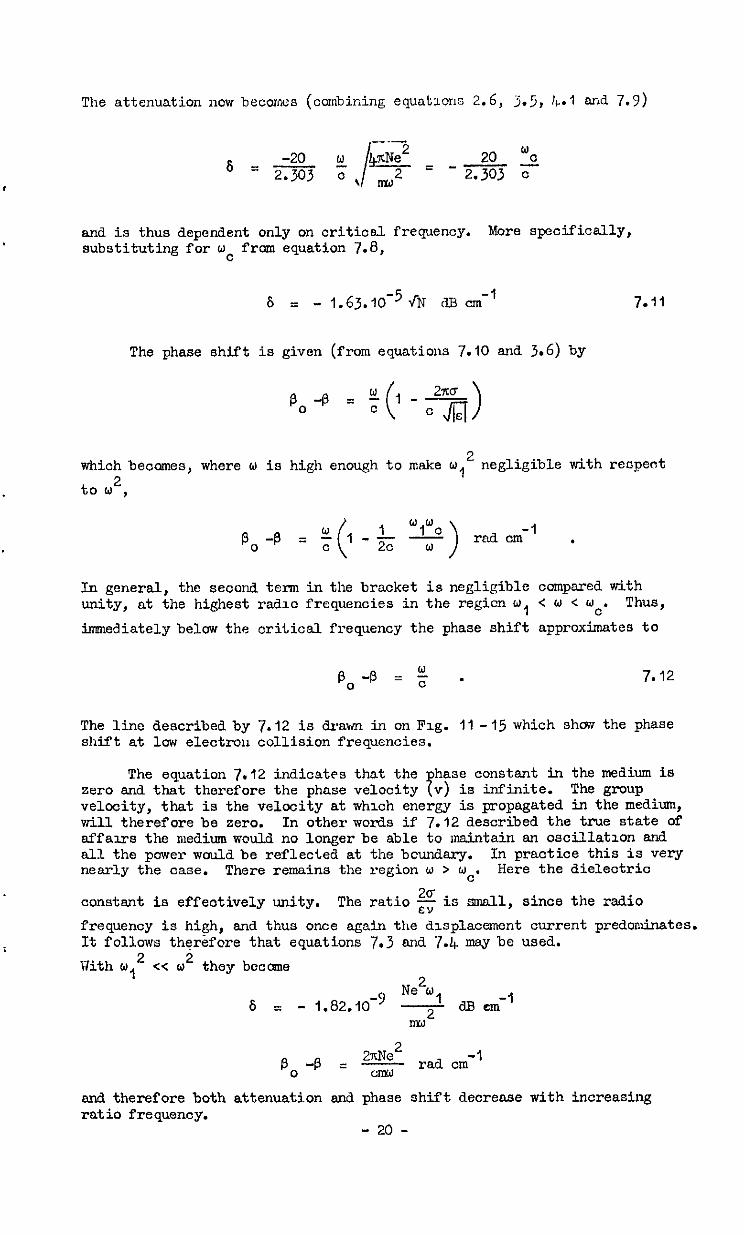
The attenuation now becomes (colnbidng equatlcns 2.6, 3.5, I+.1 end 7.9)
t
and is thus dependent only on criticel frequency. More specifically, substituting for wc from equation 7.8,
s = - 1.63.10-5 JN a3 cm-’ 7.91
The phase shift is given (from equations 7.10 and 3.6) by
P,-P = $I-*)
which becomes, where o is high enough to make w 2
1 negligible with reopeot
to 2,
P,-B = t 1-h -y- ( wl°C
>
-1 rad cm .
In general, the second term in the bracket is negligible compared with unity, at the highest raddlc frequencies in the regicn w, < w < uc. Thus,
imnediately below the critical frequency the phase shift approximates to
The line described by 7.12 is drawn in on Fig. Ii - 15 which shcuv the phase shift at low electron collision frequencies.
The equation 7.12 indicates that the hase constant in the medium is zero and that therefore the phase velocity 7 v) is infinite. The group velocity, that is the velocity at which energy is popagated in the medium, will therefore be zero. In other words if 7.12 described the true state of affau‘s the medium would no longer be able to maintain an oscillation and all the power wauld be reflected at the bcundary. In practice this is very nearly the case. There remains the region w > 6~~. Here the dielectric
constant is effectively unity. The ratio g is small, since the radio
frequency is high, end thus once again the displacement current predominates. It follows therefore that equations 7.3 and 7.4 mey be used.
Uith o 2 1 cc co2 they become
Ne"o 6 = - 1.82.10-9 - c3.B cm m21 -'
p. +.J = 22!$ -1 racl. cm
end therefore both attenuation and phase shift decrease with increasing ratio frequency.
- 20 -
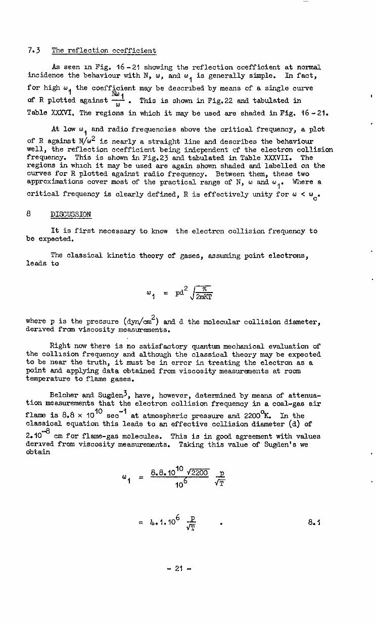
7.3 The reflection ceefficient.
As seen in Fig. 16-21 showing the reflection ccefficient at normal incidence the behaviour with N, w, and w, is generally simple. In fact,
for high w, the coefficient may be described by means of a single curve *I of R plotted against -;;- . This is shown in Fig.22 and tabulated in
Table XXXVI. The regions in which it msy be used are shaded inPig. 16-21.
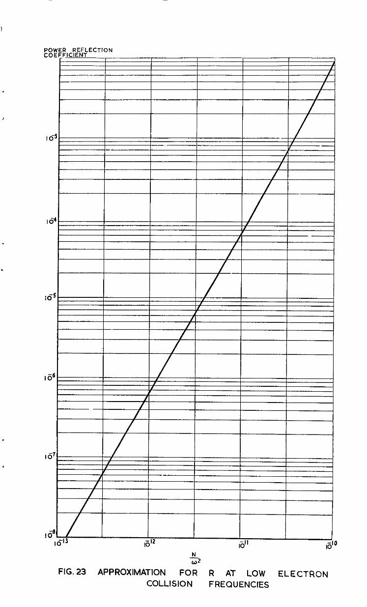
At low o, and radio frequencies above the critical frequency, a plot
of R against N/w2 is nearly a straight line and describes the behaviour well, the reflection Coefficient being independent of the electron collision frequency. This is shown in Fig.23 and tabulated in Table XXWII. The regions in which it may be used are again shown shaded and labelled on the curves for R plotted against radio frequency. Between them, these two approximations cover most of the practical range of N, w and w
I' Where a
critical frequency is clearly defined, R is effectively unity for W < UC.
8 DIKXJSSION
It is first necessary to know the electron collision frequency to be expected.
The classical kinetic theory of gases, assuming point electrons, leads to
where p is the pressure (dyn/om2) snd d the molecular collision diameter, derived from viscosity measurements.
Right now there is no satisfactory quantum mechanical evaluation of the collision frequency and although the classiosl theory maybe expected to be near the truth, it smst be in error in treating the electron as a point and applying data obtained from viscosity measurements at room temperature to flsme gases.
Beloher and Sugdenj, have, however, determined by means of attenua- tion measurements that the electron collision frequency in a coal-gas air
flame is 8.8 x IO” sea" at atmospheric pressure and 2200°K. In the classical equation this leads to an effective collision diameter (a) of
2.10 -8
cm for flame-gas molecules. This is in good agreement with values derived from viscosity measurements. Taking this value of Sugden's we obtain
w, = 8.8.10’” f-izim 2 IO6 f!F
= 4.1.106 g . 8. I
- 21 -
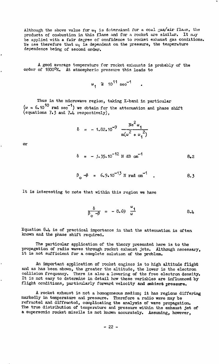
Although the above value for w, is dotermined for a coal gas/air flare, the products of corsbustion in this fl.sme rind for a rocket are similar. It ruy be applied with a fair degree of confidence to rocket exhaust gas conditions. We see therefore that w, is dependent on the pressure, the temperature dependence being of second order.
.
A good average temperature for rocket exhausts is probably of the order of 1800°K. At atmospheric pressure this leads to
WI z IO” sco-’ .
Thus in the microwave region, taking X-band in particular
(u = 6.lO'o rsd sea-') we obtain for the attenuation and phase shift (equations 7.3 and 7.4 respectively),
6 = - 1.82.10-9 Ne2bJ,
m(w2 + y2)
or
s = - 3.35.10-'2 N a0 cm-’
PO -p = 6.9.10-I3 N rad cm-' ,
It is interesting to note that within this region we have
8.2
8.3
Equation 8.4 is of practical importsnoe in that the attenuation is often known and the phase shift required.
The partioulsr application of the theory presented here is to the propagation of radio waves through rocket exhaust jets. Although necessary, it is not sufficient for a complete solution of the woblem.
An important application of roolcet engines is to high altitude flight snd as has been shown, the greater tine altitude, the lower is the electron collision frequency. There is also a lowering of the free electron density. It is not easy to determine in detail hew these variables are influenced by flight conditions, particularly forwsrd velocity and ambient pressure.
A rocket exhaust is not a homogeneous medium; it has regions differing markedly in temperature end pressure. Therefore a radio wave may be refracted and diffracted, complicating the analysis of wave propagation. The true distribution of temperature and pressure within the exhaust jet of a supersonic rooket missile is not known accurately. Assuming, however,
- 22 -
that a true plot of these variables were known, then the propagation problem is still not solved, because of the unknown electron density and collision frequency. We do not have sufficient howledge available to enable us to determine these quantities with certainty. Perhaps the largest gal) in our knowledge relates to the kinetics of the reactions occurring in the gas during its rapid expansion and hence to the electron density existing at any given point and time.
A oomplete solution of the radio prcpogation problem in rocket flight to high altitudes must therefore await further knowledge on all these points.
ACKNOiic;EMENTS
The author is indebted to EGathematiosl Services, R.A.E. Farnborcugh, for the provision of computing tune on the digital canputer, DEUCE.
NO. Author -
I Coulson, C.A.
2 bfargenau, H.
3 Belcher, II. Sugden, T. M.
Title, etc
Waves : a mathematical acocunt cf the ocmmon types of wave motion. Ch. VII Oliver and Bcyd, Ltd. Edinburgh, 1947
Conduction and dispersicn of ionised gases at high frequencies Phys. Rev. 3 (1946)
Studies on the ionization produced by metallic salts in flsmes.1. The determination of the collision frequenoy of electrons in coal-gas/air flames Proc. Roy. Soo. A, 201 (1950), 4G0 -
- 23 -
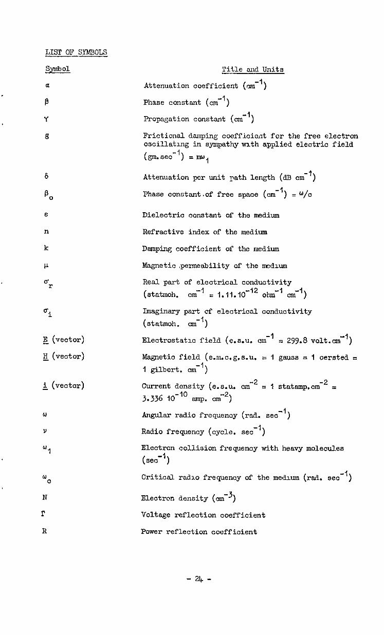
LIST OF SyMs0I.S -
SymbOl
a
B
Y
8
E
n
k
P
o- r
E (vector)
g (vector)
&, (vector)
w c
N
r
R
Title and Units -.
Attenuation coefficient (om-')
Phase constent (cm-')
Propagation constant (cm-')
Frictional dsmping coefficient for the free electron oscillating in sympathy vvlth applied electric field
(gm.seo-1) = r&J,
Attenuation per unit Path length (dB cm-')
Phase conntsnt.of free space (om-') = W/o
Dielectric constant of the medium
Refractive index of the medium
Damping coefficient of the medium
Magnetic .permeability of the medium
Real part of electrical conduotivity -1 (stahnoh. cm = 1.11.10-‘2 ohm-' cm')
Imaginary part of electrical conductivity
(statmoh. om-')
-1 Electrostatic field (e.s.u. cm = 299.8 volt.cm"')
Msgnetic field (e.m.0.g.s.u. = 1 gauss = I oersted I
1 gilbert. cm-')
-2 Current density (e.s.u. cm -2 = I statamp.cm = 3.336 lO-‘o amp. omw2)
Angulsr radio frequency (rad. se0 -1 )
Radio frequency (cycle. set -1 )
Electrcn collision frequency with heavy molecules -1
( 1 set
Criticsl rsdlo frequency of the medium (rsd. set-')
Electron density (omm3)
Voltage reflection coefficient
Power reflection coefficient
-UC-
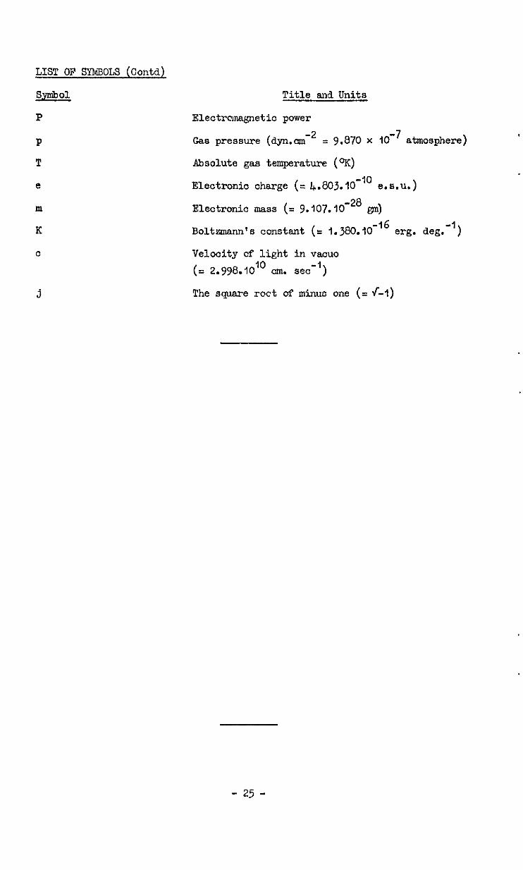
LIST OF SYM3OLY (Contd)
Symbol
P
P
T
e
m
K
0
j
Title and Units
Electrcmagnetic power
Gas pressure (dyn.cm -2 = 9.870 x 1O'7 atmosphere)
Absolute gas temperature (OK)
Electronic charge (= 4.803.10-'" e.8.u.)
Electronic mass (= 9.107.10 -28 gn)
Bolbmann's constant (= 1.380.10 -16 erg. deg. -1 )
Velocity of light in vacua
(= 2.998.iO'" -1
cm. set 1
The square roct of minus one (= f-1)
- 25 -
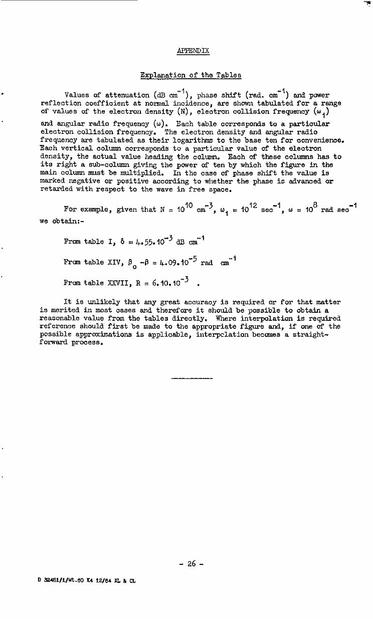
MPENDIX
Explanation of the Tables
. Values of attenuation (dB cm-'), phase shift (red. cm-') and power reflection coefficient at normal incidence, are shown tabulated for a range of values of the electron density (N), electron collision frequency (w,)
and angular radio frequency (w). Each table corresponds to a particular electron collision frequency. The electron density and angular radio frequency are tabulated as their logarithms to the bane ten for oonvenience. Each vertical column corresponds to a particular oalue uf the electron density, the actual value heding the column. Each of these columns has to its right a sub-column giving the power of ten by which the figure in the main column must be multiplied. In the case of phase shift the value is marked negative or positive according to whether the phase is advanced or retarded with respect to the wave in free space.
For example, given that N = IO IO cmm3, w, c lOI see-', w = 10 8
rad se0 -1
we obtain:-
From table I, 6 = 4.55.10e3 33 cm-'
Fran table XIV, 13, -!3 = l+.0Y.iO'5 -1 rad cm
From table XXVII, R = 6.10.10-3 .
It is unlikely that any great accuracy is required or for that matter is merited in most oases and therefore it should be possible to obtain a reasonable value from the tables directly. Where interpolation is required reference should first be made to the appropriate figure and, if one of the possible approximations is applicable, interpclation becomes a straight- forward prooess.
- 26 -
II 32461/1/Wt.80 K4 12/84 XL & n

CONDUCTIVITY ((3i)
IO’0
IO9
108
RADIO FREQUENCY rod set-’
FIG. I COMPARISON OF SIMPLE THEORY WITH THAT OF MARGENAU N-lofecm-3 w ,-108 se2
ATTENUATION dB cm’ I L I I 1 I
I o-
C”““,,“I. e - \\\\\ \\ \\\-l\ / \U\\\\l \ \ .\\w
Y\l\\!.\XX\1 I \\\\ \\\Y\\\\Y I \\\\U\\\\U\\\\Y
\\\\\?Y\\\\\\\\\l\\\\\I I
RADIO FREQUENCY rod set?
FIG. 2 VARIATION OF ATTENUATION WITH RADIO FREQUENCY u), = IO I2 see-1
ATTENUATION
IO0
-I IO
IO2
-3 IO
I I \\\ \\\\\h\\\\r\\\\ \
\ \ .I ., 40%” ”
\
\‘\I\ x-2\\ 4 \ -’ \\\\\\\ c
\ \\\\\\\,,,.,.,,,.
\\\\\\?\\\y\\\\Y\\\W I u ‘\ ‘\ \ ‘\ ‘xi ‘\ ‘\ ‘\ ‘\ ‘4 ‘\ ‘\ ‘\ ‘\ ‘i. ‘\ ‘\ ‘\ ‘1 ‘4 I
I09 10'0 IO"
RADIO FREQUENCY rod -I set
FIG. 3 VARIATION OF ATTENUATION WITH RADIO FREQUENCY w , = IO” $.ec-’
ATTENUATION dB cni’
I I I I I I
4
\‘\‘A\\4 I
IO-’ \ \ \ \ \ h \ u 1 I
J 100 IO’ IO8 IO’ 1010 IO’1
RADIO FREQUENCY rod set-1
FIG. 4 VARIATION OF ATTENUATION WITH RADIO FREQUENCY wl = IO%CC -’
II II
I \\\nx\\ \ I I I I i c\\ I/
\\\vK\\\ A ! I I I I I
N-29 / I\ I I I I I
RADIO FREQUENCY rod see-1
FIG. 5 VARIATION OF ATTENUATION WITH
RADIO FREQUENCY WI = IoQsec -I
IO6 IO’ 108 IO9 10’0 IO”
RADIO FREOUENCY rod set-I
FIG. 6 VARIATIONS OF ATTENUATION WITH RADIO FREQUENCY w, = 108 SPC -I
IO ’
IO0
I 0-1
-2 IO
Id
-4 IO
RADIO FREQUENCY rad see-’
FIG. 7 VARIATIONS OF ATTENUATION WITH RADIO FREQUENCY w , = 107sec-’
ATTENUATION dB cni’
RADIO FREQUENCY rod see-’
FIG. El VARIATION OF ATTENUATION WITH RADIO FREQUENCY WI - IO6 set -I
i \ \\\ \*
I \ \ 1’ \
-7 IO
\\
IO6 107 108 IOQ 10’0 10’1
RADIO FREQUENCY rod se?
FIG 9 VARIATION OF PHASE SHIFT WITH RADIO FREQUENCY WI = 1o’~sec -I
PHASE SHIFT rad c -’ al ’ I I
I
c\\ I I \ I I \\Y \ 1 \ . . \\A
\ I n s ’ ’
-N-1010 \ -
,6
I06 IO’ IO6 IO9 1016 101’
RADIO FREQUENCY rad se?
FIG. IO VARIATION OF PHASE SHIFT WITH . RADIO FREQUENCY WI - lol~soc-I
I
PHASE SHIFT rad Crii’ -. I I I
\h\\\\l
t \ \\\\Y \I i
-4 IO
\\ ’
12 ] \\
IO6 IO’ 108 IO9 10’0 IO”
RADIO FREOUENCY rod se?
FIG. II VARIATION OF PHASE SHIFT WITH RADIO FREQUENCY w, = 10’0 sec -1
PHAS~HIFT rad cm’
I I - I / \ , 1, -tN
IA \+
L I I I I
106 IO’ 100 IO9 I
10’0 IO”
RADIO FREOIJENCY rad sx-
FIG. 12 VARIATION OF PHASE SHIFT WITH RADIO FREQUENCY w, - to9soc-1
/ \ /
/ ,,\L / \- \
/ / / \ \
\+ \\\Y , \\\\ / I I \ \ At,,, \
I A+ A?&\\
10-z
/ I I . \ \ \ I\
1 I i
/ ‘)
\\\\X\R\\ I
p0-j3 -W I
\.\ \
I I I I I
I
16~ IO6 IO’ 108 I09
1
10’0 IO”
RADIO FREQUENCY rad set?
FIG 13 VARIATION OF PHASE SHIFT WITH RADIO FREQUENCY wI = loasec-1
Id
+\o-- ’ \ \I \ . / r\ ,&
I / i i i \ \I\ \ \ \,
I I \\h\\\\ \ \I\ \ \ \
RADIO FREQUENCY rod set?
FIG. 14 VARIATION OF PHASE SHIFT WITH
RADIO FREQUENCY wl = 107 tee-1
PHASE SHIFT rad cni’
IO45 IO6 IO’ I08 I09 10’0 101’
RADIO FREOUENCY rod Set’
FIG. IS VARIATION OF PHASE SHIFT WITH RADIO FREQUENCY WI - ,06soc-1
POWER REFLECTION rACCClrlC.IT
,
.-- _--..-.-
.\\\\A A.\.‘. .\.\.‘.‘. \
IO -I
I o-2
IO-’
10-S
IO6 IO’ 106 IO’ 1010 IO’1
RADIO FREQUENCY rod -I 5ec
FIG.16 VARIATION OF POWER REFLECTION COEFFICIENT
WITH RADIO FREQUENCY WI = lO”S~C’I
POWER REFLECTION COE
WY’
II9 I06 IO’ 106 1010
-
RADIO FREOUENCY rod set!
FIG.17 VARIATION OF POWER REFLECTION COEFFICIENT
WITH RADIO FREQUENCV WI - IO~~SOC-’
POWER REFCECTION COEFFIC-
\\‘.\\ \\\\
RADIO FREQUENCY rod set’1
.
FIG. I8 VARIATION OF POWER REFLECTION COEFFICIENT
WITH RADIO FREQUENCY WI = lo’o*~C-l
POWER REFLECTION COEFFICIENT
I
I
I I I I ,
I I I I
RADIO FREOUENCY rod se?
FIG.19 VARIATION OF POWER REFLECTION COEFFICIE’
WITH RADIO FREQUENCY WI * 10 9sec -I
POWER REFLECTION COEFFICIE”’
I I I I
\\hY \\A\
I\\’ I P-T\‘\
I I
El\\ I
106 IO’
I I Ih \ \I\ \ UI\\Y \d
106 I09 10’0 IO”
RADIO FREQUENCY rod 5eC-
FIG.20 VARIATION OF POWER REFLECTION COEFFICIENT
WITH RADIO FREQUENCY WI = lo*sec -I
POWER REFLECTION rACCClrlC.l
-I I ” ,
I I , I I I I\ \
I
I I I I I\ \.\ \
I I I \\I \
Irii ,.s I I \h\\
-.
tr
ofi-4
I \X\\\\hl\ \ \ y\\\\
I \
lci’ I I I06 IO’ 108 109 10'0 101'
RADIO FREQUENCY rad sect
FIG. 21 VARIATION OF POWER REFLECTION COEFFICIENT
WITH RADIO FREQUENCY WI = IO’SCC -I
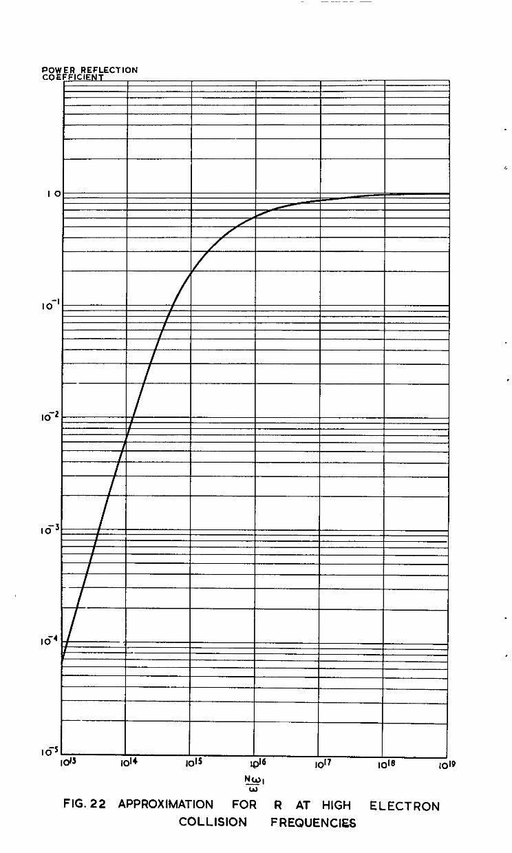
FIG. 22 APPROXIMATION FOR R AT HIGH ELECTRON COLLISION FREQUENCIES
POWER REFLECTION COEF_FjZLE-
FIG. 23 APPROXIMATION FOR R AT LOW ELECTRON COLLISION FREQUENCIES
PHASE SHIFT rad cni’ 02
I
I I I I I
FIG. 24 VARIATION OF PHASE SHIFT WITH RADIO FREQUENCY w,=107 sef1 . N = 1olOc~3
, c
____________________-------------------------------- -__----__-___-_______________ ____---______._____-_______ __-_
A.R.C. C.P. No 764 621 396 82: 621 455.019 9
RADIO PROPAGATION TBROUCB ROCKET EXAWST JETS: PART I ELECTROHA~TIC WAK? PROPAGATION IN AN IONISED ~IUPI. Wllllams. H. February, l9S9.
TD.e attenuation per "nit path length, phase &lit pei- "nit path length and reflectlan caefflclent at the boundary a.8 dwlved theoretl- cslly ror 8 medium containing rree electmns, In terns of the electron dmslty. electron colllalon rrequenw with heavy molecules and the applied radio irequenw.
Numerical results are tabulated over wide ranges or the three Numerical Rsults we tabulated over Plde ranges or the three variables. Blld these results BPB also presented graghlcally. nrlables, and these .-es"lts are also presented graphloaUy.
Useful appmxlmatlons to the oo"p1H.e theory are derived and the regions In v&,lch those m&y be applied In PI‘actloe an lndloated
Userul apPR3llmatlonS to the complete theoN an3 derlwd end the regions In which these may be applied In pi-aotlce we lndlcsted.
A.R.C C.P. NO. 784
MI0 PROPAGATION TBROU@ ROCKXT EXBAUST JETS PART I ELECTROMA~TIC WAVE PROPAGATION IN AN IONISED MELIIUM. Wlllla"S. II February, 1959
The attenuation per unit path lengui. phase shirt per unit path length and rerlectlon coerrlclent at the boundary are derived theorstl- cany ror a medium contamlng rm electrons. in mm or the electrm density. electron oolllslon rrequenw with heavy molecule9 and tbs applied radio rrewenoy
A.R C C.P. No 784
RADIO PROPAGATION TKROUM ROCKET EXHAUST JETS. PART I ELECTROMAG'4ETIC WA"'2 PROPAGATION IN AN IONISED MEOIUn Wllllams, A Febnw. 1959
me 8.ttenm.i0n per tat path length. phase shirt per unit path length and r6rleOtlOn coerrlolent at the boundary are derived thee-sfl- cauy ror a meam cm.*mg rree electrons. In terns or the elactr33 density, electron oolllslon Ii-eqnenoy with heavy molecules 2nd the applied radio rreqllenw
Numerical results are tabulated OY~= nlde ranges ',I the three "arlables, end these results are also presated g-aphlsally
"sehll wproflmatlons to the COnplete theory a-e derived and the regions In aloh these may be applied In praotlce a-e lndlcated.


C.P. No. 764
0 Crown copyrrghf 1965
Prmted and pubbshed by
HER MAJESTY’S STATIONERY OFFICE
To be purchased from York House, Kmgsway, London w c 2
423 Oxford Street, London w I 13~ Castle Street, Edmburgh 2
109 St Mary Street, Cardtff 39 Kmg Street, Manchester 2
50 Faxfax Street, Bristol 1 35 Smallbrook, Rmgway, Btrmmgham 5
80 ChIchester Street, Belfast I or through any bookseller
Prmred m England
C.P. No. 764
S.O. Code No. 23-9015-64