radio equipment used for tdma digital ... radio transmission of digitized information signals. 2.2...
TRANSCRIPT

ARIB STD-T101
ARIB STANDARD
Association of Radio Industries and Businesses
ARIB STD-T101 Version 2.0
RADIO EQUIPMENT USED FOR TDMA
DIGITAL ENHANCED CORDLESS TELECOMMUNICATIONS
Version 1.0 March 28th 2011 Version 1.1 July 7th 2011 Version 1.2 December 18th 2012 Version 1.3 July 31st 2014 Version 2.0 January 22nd 2018
ENGLISH TRANSLATION

ARIB STD-T101
General Notes to the English Translation of ARIB Standards
and Technical Reports
1. Notes on Copyright
- The copyright of this document is ascribed to the Association of Radio Industries and
Businesses (ARIB).
- All rights reserved. No part of this document may be reproduced, stored in a retrieval system
or transmitted, in any form or by any means, without the prior written permission of ARIB.
2. Notes on English Translation
- ARIB Standards and Technical Reports are usually written in Japanese. This document is a
translation into English of the original document for the purpose of convenience of users. If
there are any discrepancies in the content, expressions, etc. between the original document
and this translated document, the original document shall prevail.
- ARIB Standards and Technical Reports, in the original language, are made publicly available
through web posting. The original document of this translation may have been further revised
and therefore users are encouraged to check the latest version at an appropriate page under the
following URL:
http://www.arib.or.jp/english/index.html.
ARIB STD-T101
Foreword The Association of Radio Industries and Businesses (ARIB) investigates and summarizes the basic technical requirements for various radio systems in the form of “ARIB Standards”. These standards are developed with the participation of and through discussions amongst radio equipment manufacturers, telecommunication operators, broadcasting equipment manufacturers, broadcasters and users. ARIB Standards include “government technical regulations” (mandatory standard) that are set for the purpose of encouraging effective use of frequency and preventing interference with other spectrum users, and “private technical standards” (voluntary standards) that are defined in order to ensure compatibility and adequate quality of radio equipment and broadcasting equipment as well as to offer greater convenience to radio equipment manufacturers, telecommunication operators, broadcasting equipment manufacturers, broadcasters and users. This ARIB Standard is developed for RADIO EQUIPMENT USED FOR TDMA DIGITAL ENHANCED CORDLESS TELECOMMUNICATIONS. In order to ensure fairness and transparency in the defining stage, the standard was set by consensus at the ARIB Standard Assembly with the participation of both domestic and foreign interested parties from radio equipment manufacturers, telecommunication operators, broadcasting equipment manufacturers, broadcasters and users. ARIB sincerely hopes that this ARIB Standard will be widely used by radio equipment manufacturers, telecommunication operators, broadcasting equipment manufacturers, broadcasters and users.
NOTE:
Although this ARIB Standard contains no specific reference to any Essential Industrial Property Rights relating thereto, the holders of such Essential Industrial Property Rights state to the effect that the rights listed in the Attachment 1 and 2, which are the Industrial Property Rights relating to this standard, are held by the parties also listed therein, and that to the users of this standard, in the case of Attachment 1, such holders shall not assert any rights and shall unconditionally grant a license to practice such Industrial Property Rights contained therein, and in the case of Attachment 2, the holders shall grant, under reasonable terms and conditions, a non-exclusive and non-discriminatory license to practice the Industrial Property Rights contained therein. However, this does not apply to anyone who uses this ARIB Standard and also owns and lays claim to any other Essential Industrial Property Rights of which is covered in whole or part in the contents of the provisions of this ARIB Standard.

ARIB STD-T101
Attachment 1 (selection of option 1)
(N/A)
Attachment 2 (selection of option 2)
PATENT HOLDER NAME OF PATENT REGISTRATION NO./ APPLICATION NO. REMARKS
Sony Corporation A comprehensive confirmation form has been submitted with regard to ARIB STD-T101 Ver. 1.3.

ARIB STD-T101
-i-
Contents
Foreword
Chapter 1 General Descriptions ....................................................................................................... 1
1.1 Outline ......................................................................................................................................... 1
1.2 Scope of application .................................................................................................................... 1
1.3 Normative References................................................................................................................. 1
1.4 Informative References ............................................................................................................... 1
Chapter 2 Standard System ............................................................................................................. 3
2.1 Overview of the Standard System ............................................................................................. 3
2.2 Structure of the Standard System ............................................................................................. 3
Chapter 3 Technical Requirements for Radio Equipment .............................................................. 4
3.1 General Conditions ..................................................................................................................... 4
3.2 Transmitter ................................................................................................................................. 9
3.3 Receiver ..................................................................................................................................... 13
3.4 Handset ..................................................................................................................................... 14
Chapter 4 Systems Interoperability .............................................................................................. 15
4.1 System Outline etc. ................................................................................................................... 15
4.2 Transmission Protocols etc. ...................................................................................................... 15
Chapter 5 Measurement Method ................................................................................................... 20
Annex 1 Test Items Associated with Specified Radio Equipment ................................................ 21
Annex 2 Operation Guidelines ....................................................................................................... 22
Annex 3 Compliance of radiation protection ................................................................................. 27
Change History

ARIB STD-T101
-ii-

ARIB STD-T101
-1-
Chapter 1 General Descriptions
1.1 Outline
The standard defines requirements for radio equipment used for TDMA digital enhanced
cordless telecommunications stipulated in Article 49.8.2.2 of Ordinance Regulating Radio
Equipment.
1.2 Scope of application
The standard defines the radio equipment as shown in Figure 1-1.
The standard does not prescribe transmission protocols, the requirements for interoperability,
but the systems designed for mutual connection (hereafter called "systems interoperability")
refer to Chapter 4.
Figure 1-1 Scope of Application
1.3 Normative References
In the standard, "RERL" refers to Regulations for Enforcement of the Radio Law, "ORE" refers
to Ordinance Regulating Radio Equipment, "OTRCC" refers to Ordinance Concerning Technical
Regulations Conformity Certification etc. of Specified Radio Equipment, "NT" refers to a
Notification of the Ministry of Posts and Telecommunications if issued in 2000 or earlier, and a
Notification of the Ministry of Internal Affairs and Communications if issued in 2001 or later.
1.4 Informative References
[1] ETSI EN 300 175 Part 1 (Overview).
[2] ETSI EN 300 175 Part 2 (Physical Layer (PHL))
[3] ETSI EN 300 175 Part 3 (Medium Access Control (MAC) layer)

ARIB STD-T101
-2-
[4] ETSI EN 300 175 Part 4 (Data Link Control (DLC) layer)
[5] ETSI EN 300 175 Part 5 (Network (NWK) layer)
[6] ETSI EN 300 175 Part 6 (Identities and addressing)
[7] ETSI EN 300 175 Part 7 (Security features)
[8] ETSI EN 300 175 Part 8 (Speech and audio coding and transmission)
[9] ETSI Collective Letter 1943 (USAGE REQUIREMENTS FOR ETSI TRADE MARKS
AND LOGOS)

ARIB STD-T101
-3-
Chapter 2 Standard System
2.1 Overview of the Standard System
The radio stations of TDMA digital enhanced cordless telecommunications are designed to
perform radio transmission of digitized information signals.
2.2 Structure of the Standard System
The standard system of TDMA digital enhanced cordless telecommunications consists of Base
units, Handsets, and Repeaters.
Base unit
A base unit refers to radio equipment that is used mainly at a fixed location (except those
which have a function for relaying radio communications).
Handset
A handset refers to radio equipment other than base units (except those which have a
function for relaying radio communications).
Repeater
A repeater refers to radio equipment that relays communications between a base unit
and a handset. Regarding technical requirements for repeaters, transmissions from the
handset to the base unit (up-link) are subject to the technical requirements for the
handset, and transmissions from the base unit to the handset (down-link) are subject to
the technical requirements for the base unit. If there are specific stipulations for the
repeater, this provision does not apply.

ARIB STD-T101
-4-
Chapter 3 Technical Requirements for Radio Equipment
3.1 General Conditions
(1) Operating frequency band
(RERL, Article 6)
(NT, No.471, 2012, Attached Table No.8-6)
Emissions of a frequency of 1,895.616 MHz or an integral multiple of 1,728 kHz added to
1,895.616 MHz in a range from 1,895.616 MHz to 1,904.256 MHz shall be used.
(2) Emission class and use
(RERL, Article 6)
(NT, No.427, 2012)
Emission class and use are as listed in Table 3-1.
Table 3-1 Emission Class and Use
Frequency Emission class Use
1,895.616 MHz,
1,897.344 MHz,
1,899.072 MHz,
1,900.8 MHz,
1,902.528 MHz,
1,904.256 MHz
D1C, D1D, D1E, D1F, D1X,
D7C, D7D, D7E, D7F, D7W, D7X,
F1C, F1D, F1E, F1F, F1X,
F7C, F7D, F7E, F7F, F7W, F7X,
G1C, G1D, G1E, G1F, G1X,
G7C, G7D, G7E, G7F, G7W, G7X
Control channel,
Traffic channel
(3) Interference prevention function
(RERL, Article 6.2)
(ORE, Article 9.4)
The radio equipment shall mainly be used in the same premises. It shall automatically
transmit/receive identification codes.
(4) Identification sign length
(NT, No.424, 1994)
The identification sign length of a base unit is 40bit. The identification sign length of
radio equipment other than base units is 36bit.

ARIB STD-T101
-5-
(5) Communication method
(ORE, Article 49.8.2.2)
For transmission from a base unit to a handset (including those transferred by repeater),
the communication method shall be time division duplex operation based on time
division multiplexing. For transmission from a handset to a base unit (including those
transferred by repeater), the communication method shall be time division duplex
operation based on time division multiple access.
(6) Frame configuration
(ORE, Article 49.8.2.2)
(NT, No.294, 2017)
The frame configuration is as shown in Figure 3-1.
A combination of full slots and double slots can be used in a frame.
Figure 3-1 Frame Configuration
(7) Cabinet
(ORE, Article 49.8.2.2)
The radio equipment shall be contained within a single enclosure that is not easy to open
excluding antenna.
(8) Carrier sense
a) When preparing to emit a radio wave, emission in the respective channel shall be
enabled only if the received power of radio waves from any radio station other than the
communication pair in the channel to be used for emission and the corresponding
channel to be used for reception is -62 dBm or lower for at least 2 consecutive frames.
(ORE, Article 49.8.2.2)
(NT, No.294, 2017)
(NT, No.424, 1994)

ARIB STD-T101
-6-
b) The measured level of radio waves received from any radio station other than the
communication pair in the channel to be used for emission and the corresponding
channel to be used for reception for at least 2 consecutive frames (hereafter called the
"interference level") shall be evaluated using two carrier sense levels called Level 1
and Level 2. The carrier sense level values are given in Table 3-2.
Table 3-2 Carrier Sense Levels
Level 1 -82 dBm
Level 2 -62 dBm
Frequencies shall be divided into Carrier Group 1 and Carrier Group 2. Carrier group
values are given in Table 3-3.
Table 3-3 Carrier Groups
Carrier Group 1 1,895.616 MHz, 1,897.344 MHz, 1,902.528 MHz,
1,904.256 MHz
Carrier Group 2 1,899.072 MHz, 1,900.8 MHz
When selecting a channel for radio wave emission, the priority sequence shall be as
follows, in descending order: a channel in Carrier Group 1 with Level 1 or lower, a
channel in Carrier Group 2 with Level 1 or lower, a channel in Carrier Group 1 with
Level 2 or lower, a channel in Carrier Group 2 with Level 2 or lower.
c) When selecting a channel for radio wave emission, if the radio station has restrictions
regarding the slots that can be used, channel selection as stipulated in b) shall be
carried out for the available slots.
d) The reception bandwidth when measuring the interference level shall be at least equal
to the bandwidth of the signal to be emitted.
e) The reception power when measuring the interference level shall be the maximum
value for the frequency to be used for transmission and the occupied time duration.
f) When intending to start a transmission (including in a control channel or a broadcast
channel without the provision for response), the radio station selecting the channel for
communication shall measure the interference level immediately before emitting a
radio wave.
g) When intending to start a transmission, a radio station for which a channel has been
specified by the transmission partner station may use the saved interference level

ARIB STD-T101
-7-
information (called the "channel list", to be updated at least every 30 seconds) for
evaluation and may start radio wave emission if the respective channel is at or below
level 2.
(9) Protection of TDMA narrow-band digital cordless telecommunications
a) When the base unit prepares to emit a radio wave at 1,899.072 MHz, or 1,900.8 MHz,
emission shall only be enabled if the received power in the TDMA narrow-band digital
cordless telephone control channel (which is emitted at 1,898.45 MHz or 1,900.25 MHz)
is -82 dBm or lower. However, if the radiated power is 1 mW or less at 1,899.072 MHz
or the radiated power is 0.3 mW or less at 1,900.8 MHz, the radio wave emission would
be allowed unless compensating for the decrease in radiated power with the antenna
gain.
(ORE, Article 49.8.2.2)
(NT, No.294, 2017)
(NT, No.424, 1994)
b) If received power of the TDMA narrow-band digital cordless telephone control channel
at the 1,899.072 MHz and 1,900.8 MHz frequency is continuously at -82 dBm or lower
for at least 300 ms, the base unit shall regard it as absence of that control channel. If
received power exceeds -82 dBm, this shall regard it as presence of a radio wave for the
TDMA narrow-band digital cordless telephone control channel.
c) When the base unit has determined that there is a radio wave of the TDMA
narrow-band digital cordless telephone control channel, it shall report that new radio
wave emission at 1,899.072 MHz or 1,900.8 MHz is restricted. If the respective
frequency is already being used for communication, continuous radio wave emission for
this communication shall be allowed.
d) When using the 1,899.072 MHz or 1,900.8 MHz frequency, the same channel may not
be occupied for more than 8 hours.
e) If the base unit cannot determine the presence or absence of a radio wave due to the
TDMA narrow-band digital cordless telephone control channel immediately before
starting radio wave emission at 1,899.072 MHz or 1,900.8MHz the presence/absence
evaluation shall be made according to the following method.
(a) The base unit shall use the latest information about the presence/absence of a
radio wave due to the TDMA narrow-band digital cordless telephone control
channel at the time of power-up, system reset, and during operation as a basis for
ARIB STD-T101
-8-
evaluation.
(b) The base unit shall evaluate the presence/absence of a radio wave due to the
TDMA narrow-band digital cordless telephone control channel at least once every
hour.
(c) The base unit, when evaluating the presence/absence of a radio wave due to the
TDMA narrow-band digital cordless telephone control channel at the time of
power-up or a system reset, shall take evaluation failure due to overlapping radio
waves from other radio stations as equivalent to the presence of a radio wave in
the TDMA narrow-band digital cordless telephone control channel.
(d) The base unit, when evaluating the presence/absence of a radio wave due to the
TDMA narrow-band digital cordless telephone control channel during operation,
shall continue to use the previous evaluation result if evaluation fails due to
overlapping radio waves from other radio stations, or due to overlapping with the
channel or slot used by the radio station itself.
f) When the handset intends to emit a radio wave at 1,899.072 MHz or 1,900.8 MHz,
emission shall be enabled only when the use of those carrier frequencies are not
restricted. However, if the radiated power is 1 mW or less at 1,899.072 MHz or the
radiated power is 0.3 mW or less at 1,900.8 MHz, the radio wave emission would be
allowed unless compensating for the decrease in radiated power with the antenna gain.
g) When the base unit has determined that there is a radio wave of the TDMA
narrow-band digital cordless telephone control channel, it shall comply with the
following conditions in the case of emitting a radio wave that burst length shorter than
0.3125 ms as a control channel.
(a) Emissions of a frequency of 1,895.616 MHz or 1,902.528 MHz shall be used.
(b) Emissions of a frequency of 1,897.344 MHz or 1,904.256 MHz can be used only
when frequencies of 1,895.616 MHz and 1,902.528 MHz cannot be used.
(c) When using the 1,897.344 MHz or 1,904.256 MHz frequency, the same channel
shall not be occupied for more than 1 hour. (*)
(*) When continuously radiating radio waves with a burst length shorter than
0.3125 ms at frequencies other than 1,895.616 MHz or 1,902.528 MHz, it is
desirable to design or operate so that it will be used for a short time.
(10) Interference avoidance
a) During a communication session, communication quality shall be monitored by
suitable means.

ARIB STD-T101
-9-
b) Communication quality shall also be monitored by suitable means when using a
control channel or a broadcast channel without the provision for response.
c) If interference occurs during communication, interference avoidance measures shall be
possible on a channel basis.
d) Interference avoidance measures shall include slot position switching, frequency
switching, transmission stop, etc.
(11) Failure
(ORE, Article 49.8.2.2)
When emissions are radiated continuously because of a failure in the radio equipment,
the radiation shall be automatically stopped before the radiation continues for 60
seconds.
(12) Operation for stopping communications
(ORE, Article 49.8.2.2)
When operation for stopping communications is performed or emissions of traffic
channels are not received, the radiation of emissions shall be stopped automatically.
3.2 Transmitter
(1) Frequency tolerance
(ORE, Article 5, Attached Table No.1)
The frequency tolerance shall be 10 x 10-6 (10ppm).
(2) Permissible value for occupied bandwidth
(ORE, Article 6, Attached Table No.2)
The permissible value for occupied bandwidth shall be 1,728 kHz or less.
(3) Permissible values for unwanted emission intensity
(ORE, Article 7, Attached Table No.3)
a) Permissible value for unwanted emission intensity in spurious range (except for
frequency bands listed in c)
Average power -36 dBm or less in any 1 MHz band
b) Permissible value for unwanted emission intensity in out-band range (except for
frequency bands listed in c)
(a) Higher than 864 kHz to 1,228 kHz from center frequency:

ARIB STD-T101
-10-
Average power -5.6 dBm or less in any 192 kHz band
(b) Higher than 1,228 kHz to 2,592 kHz from center frequency:
Average power -9.5 dBm or less in any 1 MHz band
(c) Higher than 2,592 kHz to 4,320 kHz from center frequency:
Average power -29.5 dBm or less in any 1 MHz band
c) Permissible value for unwanted emission intensity in the frequency range between
higher than 1,891.296 MHz and 1,893.146 MHz and between higher than 1,906.1 MHz
and lower than 1,906.848 MHz
(a) Higher than 1,892.846 MHz to 1,893.146 MHz, or higher than 1,906.1 MHz to
lower than 1,906.754 MHz:
Average power -31 dBm or less in any 192 kHz
(b) Higher than 1,891.296 MHz to 1,892.846 MHz, or 1,906.754 MHz to lower than
1,906.848 MHz:
Average power -36 dBm or less in any 192 kHz
(4) Tolerance for antenna power
(ORE, Article 14)
The tolerance for antenna power shall be +20%, -50%.
(5) Modulation method
(ORE, Article 49.8.2.2)
The modulation method shall be FSK, π/2-BPSK, π/4-QPSK, π/8-8PSK, 16QAM, or
64QAM.
(6) Carrier off time leakage power
(ORE, Article 49.8.2.2)
During communication, the leakage power shall be 80 nW or less when the carrier is not
transmitted.
(7) Transmission rate of modulation signal
(ORE, Article 49.8.2.2)
(NT, No.294, 2017)
The transmission rate of modulation signal shall be as shown in Table 3-4.

ARIB STD-T101
-11-
Table 3-4 Transmission Rate of Modulation Signal
Modulation method Transmission rate of modulation signal
FSK, π/2-BPSK 1,152 kbit/s
π/4-QPSK 2,304 kbit/s
π/8-8PSK 3,456 kbit/s
16QAM 4,608 kbit/s
64QAM 6,912 kbit/s
(8) Tolerance for transmission rate of modulation signal
(NT, No.294, 2017)
The tolerance for transmission rate of modulation signal shall be 100 x 10-6.
(9) Antenna power
The antenna power shall be 240 mW or less.
(RERL, Article 6)
(ORE, Article 49.8.2.2)
The antenna power is the average power during the burst transmission.
(10) Absolute gain of the antenna
(ORE, Article 49.8.2.2)
The absolute gain of the antenna shall be 4 dB or less. However, when the effective
radiated power is equal to or less than the value obtained by applying an antenna power
of 240 mW to the antenna with its absolute gain being 4 dB, the shortage shall be
compensated for by the gain of the antenna.
(11) Control of the antenna power
(ORE, Article 49.8.2.2)
In the case of equipment having a function of automatically controlling the antenna
power so as to be the minimum necessary, it can control the antenna power by measuring
the received power of the radio wave from the other radio station of the communication.
(12) Tolerance of Specific Absorption Rate in human body (excluding head and both hands)
Specific Absorption Rate (defined as a numerical value divided the electromagnetic
energy absorption into 10g of tissue within 6 minutes by 10 g then again by 6 minutes) of
ARIB STD-T101
-12-
human exposure (excluding head and both hands) to radio wave (multiple radio waves in
the case of combining with other transmitting devices in the same cabinet) from radio
equipment shall be 2 W/kg (4 W/kg in case of limb). However, this measurement of SAR
may be omitted for the following radio equipment as being deemed to comply with this
provision.
a) Radio equipment with 20 mW or less of the average transmission power (total
transmission power in case of multiple radio transmitters).
b) The distance between the radio equipment with the radiating antenna and the human
body (excluding the head and both hands) is exceeding 20 cm.
c) Radio equipment certified by the technical standard conformity certificate etc. by
August 31, 2018 according to the old technical standards prior to October 1, 2017.
(ORE, Article 14.2.1)
(OTRCC, Article 6 and 25, Attached Table No.1)
The average transmission power emitted by the radio equipment refers to the time
average power in the case of continuous burst transmission using the maximum
number of channels (excluding at the time of channel switching) that can be taken in
the normal operation.
(13) Tolerance of Specific Absorption Rate in human head
(ORE, Article 14.2.2)
(OTRCC, Article 6 and 25, Attached Table No.1)
Specific Absorption Rate of human head exposure to radio wave (multiple radio waves in
the case of combining with other transmitting devices in the same cabinet) from radio
equipment shall be 2 W/kg. However, this measurement of SAR may be omitted for the
following radio equipment as being deemed to comply with this provision.
a) Radio equipment with 20 mW or less of the average transmission power (total
transmission power in case of multiple radio transmitters).
b) Radio equipment which is no other than the portable use.
c) Radio equipment which is not used in close proximity to the human head.
d) Radio equipment certified by the technical standard conformity certificate etc. by
August 31, 2018 according to the old technical standards prior to October 1, 2017.
ARIB STD-T101
-13-
3.3 Receiver
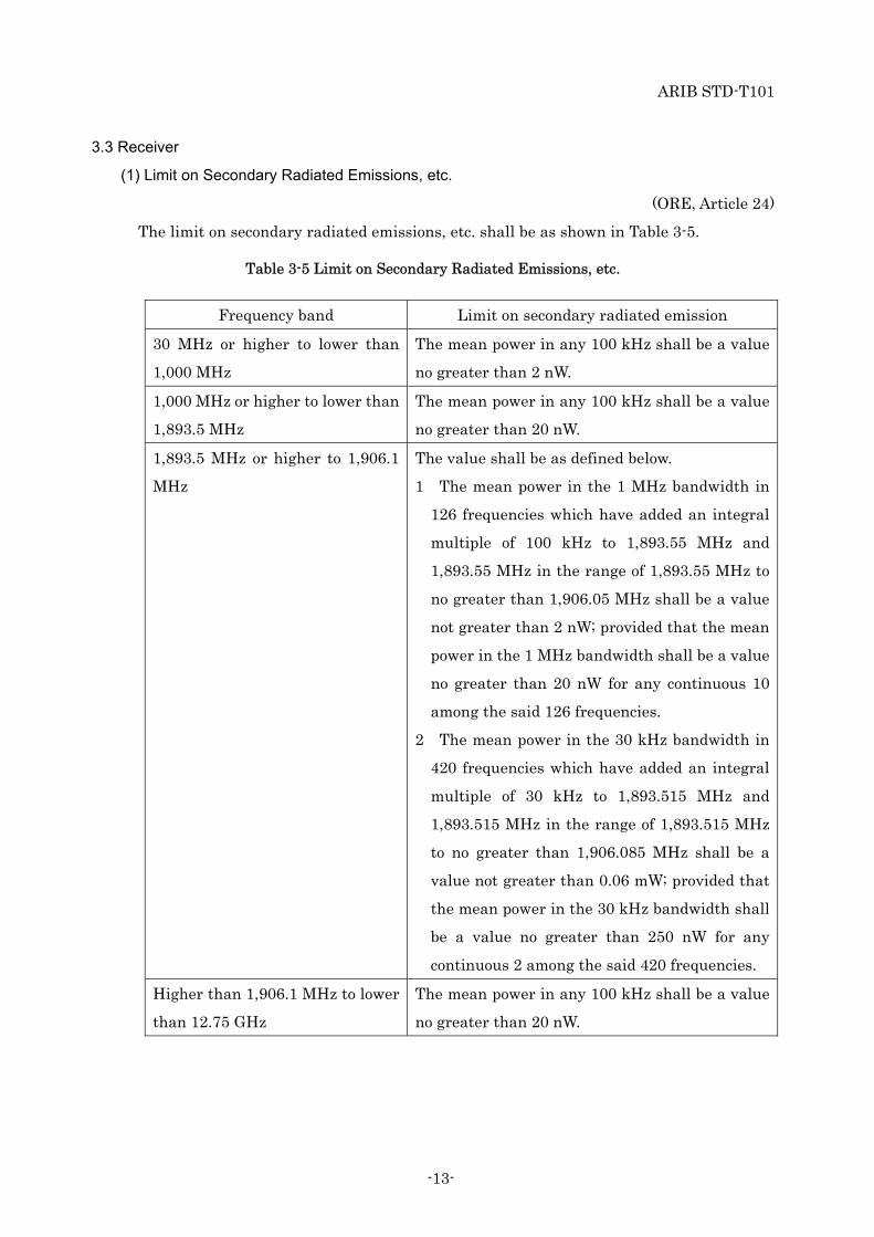
(1) Limit on Secondary Radiated Emissions, etc.
(ORE, Article 24)
The limit on secondary radiated emissions, etc. shall be as shown in Table 3-5.
Table 3-5 Limit on Secondary Radiated Emissions, etc.
Frequency band Limit on secondary radiated emission
30 MHz or higher to lower than
1,000 MHz
The mean power in any 100 kHz shall be a value
no greater than 2 nW.
1,000 MHz or higher to lower than
1,893.5 MHz
The mean power in any 100 kHz shall be a value
no greater than 20 nW.
1,893.5 MHz or higher to 1,906.1
MHz
The value shall be as defined below.
1 The mean power in the 1 MHz bandwidth in
126 frequencies which have added an integral
multiple of 100 kHz to 1,893.55 MHz and
1,893.55 MHz in the range of 1,893.55 MHz to
no greater than 1,906.05 MHz shall be a value
not greater than 2 nW; provided that the mean
power in the 1 MHz bandwidth shall be a value
no greater than 20 nW for any continuous 10
among the said 126 frequencies.
2 The mean power in the 30 kHz bandwidth in
420 frequencies which have added an integral
multiple of 30 kHz to 1,893.515 MHz and
1,893.515 MHz in the range of 1,893.515 MHz
to no greater than 1,906.085 MHz shall be a
value not greater than 0.06 mW; provided that
the mean power in the 30 kHz bandwidth shall
be a value no greater than 250 nW for any
continuous 2 among the said 420 frequencies.
Higher than 1,906.1 MHz to lower
than 12.75 GHz
The mean power in any 100 kHz shall be a value
no greater than 20 nW.

ARIB STD-T101
-14-
3.4 Handset
(1) Radio communication which is performed between two or more handsets (limited to the
handsets which memorize an identification sign of the same base unit)
(ORE, Article 49.8.2.2)
Radio communication which is performed between two or more handsets (limited to the
handsets which memorize an identification sign of the same base unit), and for which a
base unit is bypassed, shall comply with the conditions below.
a) Emissions of a frequency of 1,895.616 MHz or 1,897.344 MHz shall be used.
b) The call duration shall not exceed 30 minutes.
c) After a call termination, the radiation of emissions shall be stopped for 1/90 or longer
(at least two seconds) of the time required for the call.
(2) Radio communication which is performed between two or more handsets (limited to the
handsets which don't memorize an identification sign of the same base unit)
(ORE, Article 49.8.2.2)
(NT, No.294 2017)
Radio communication which is performed between two or more handsets (limited to the
handsets which don't memorize an identification sign of the same base unit), and for
which a base unit is bypassed, shall comply with the conditions below.
a) Emissions of a frequency of 1,895.616 MHz shall be used.
b) The call duration shall not exceed 30 minutes.
c) After a call termination, the radiation of emissions shall be stopped for 1/90 or longer
(at least two seconds) of the time required for the call.

ARIB STD-T101
-15-
Chapter 4 Systems Interoperability
The systems interoperability refers to the documents indicated below. (Informative)
If the specifications of Chapter 3 and the documents overlap, the specifications of Chapter 3
shall be met.
4.1 System Outline etc.
ETSI EN 300 175 Part 1 (Overview)
4.2 Transmission Protocols etc.
4.2.1 Common interface
(1) Physical layer
ETSI EN 300 175 Part 2 (Physical Layer (PHL))
(2) Medium access control layer
ETSI EN 300 175 Part 3 (Medium Access Control (MAC) layer)
(3) Data link control layer
ETSI EN 300 175 Part 4 (Data Link Control (DLC) layer)
(4) Network layer
ETSI EN 300 175 Part 5 (Network (NWK) layer)
(5) Identities and addressing
ETSI EN 300 175 Part 6 (Identities and addressing)
(6) Security
ETSI EN 300 175 Part 7 (Security features)
(7) Audio
ETSI EN 300 175 Part 8 (Speech and audio coding and transmission)

ARIB STD-T101
-16-
4.2.2 RF carrier number
4.2.2.1 RF carrier numbering type
Two kinds of RF carrier numbering types are used to show the RF carrier number. The
system uses either.
(1) Simplified numbering
The system uses only basic RF carrier number which is in the set {0,1,2,3,4,5,6,7,8,9}.
However the set {5,6,7,8} are reserved and not used. The RF carrier number assignment
shall be as shown in Table 4-1.
(This RF carrier numbering is Japan specific de facto standard due to the frequency
allocation.)
Table 4-1 RF carrier Number Assignment
RF carrier number RF carrier frequency
4 1,895.616 MHz
3 1,897.344 MHz
2 1,899.072 MHz
1 1,900.8 MHz
0 1,902.528 MHz
9 1,904.256 MHz
(2) ETSI Standard numbering
ETSI EN 300 175 Part 2 (Physical Layer (PHL)) Annex F.2
The system uses an extended RF carrier number which is in the set {10,11,12, … ,63} in
addition to the basic RF carrier number. This RF carrier numbering refer to the ETSI
standard. The RF carrier number assignment shall be as shown in Table 4-2.
Table 4-2 RF carrier Number Assignment
RF carrier number RF band number RF carrier frequency
1 - 1,895.616 MHz
0 - 1,897.344 MHz
10 00001 1,899.072 MHz
11 00001 1,900.8 MHz
12 00001 1,902.528 MHz
13 00001 1,904.256 MHz

ARIB STD-T101
-17-
4.2.2.2 Reporting of the RF carrier numbering type
ETSI EN 300 175 Part 3 (Medium Access Control (MAC) layer), 7.2.3.2.7 Extended RF carrier
information available (Mc)
The RF carrier numbering type in the system is classified by the “Extended RF carrier
information available (Mc)” in the “Static system information” message over the dummy
bearer, and it shall be as shown in Table 4-3.
Table 4-3 Extended RF carrier information available (Mc)
Bit RF carrier numbering type
a21
0 Simplified numbering :
no “extended RF carrier information” message
1 ETSI Standard numbering :
“extended RF carrier information” message shall be transmitted in the
next multiframe
4.2.3 Reporting of available carrier frequencies
ETSI EN 300 175 Part 3 (Medium Access Control (MAC) layer), 7.2.3.2.8 RF carriers available
(RF-cars) and 7.2.3.3 Extended RF carrier information part 1
(1) Simplified numbering
Available RF carrier numbers are indicated in the set of “RF carriers available
(RF-cars)” field in the “Static system information” message over the dummy bearer.
“RF carriers available (RF-cars)” shall be as shown in Table 4-4.
Table 4-4 RF carriers available (RF-cars)
Bit Meaning
ax, 22≦x≦31
0 Carrier number (x-22) is not available
1 Carrier number (x-22) is available
(2) ETSI Standard numbering
The available RF carrier numbers for the basic carriers can be same as the case of the
simplified numbering. And the available RF carrier numbers for the extended carriers
are indicated in the set of “Extended RF carriers available (Extended RF-cars)” field in

ARIB STD-T101
-18-
the “Extended RF carrier information part 1” message over the dummy bearer.
“Extended RF carriers available (Extended RF-cars)” shall be as shown in Table 4-5.
Table 4-5 Extended RF carriers available (Extended RF-cars)
Bit Meaning
ax, 12≦x≦34
0 Extended carrier number (x-2) is not available
1 Extended carrier number (x-2) is available
4.2.4 Reporting of the carrier frequencies with restriction on use
ETSI EN 300 175 Part 3 (Medium Access Control (MAC) layer), 7.2.4.3.9 Active carriers
Even at the available carrier frequency, in the case of imposing restrictions on the use of the
carrier frequency, the target carrier frequencies would be notified by the base unit or the
repeater. This target with usage restriction is indicated in the set of “active carriers” of “MAC
Layer information” field in the “short page” message or “zero length page” message. The RF
carrier frequency and meaning assigned to each bit are shown in Table 4-6.
Table 4-6 Carrier Frequency Assignment and meaning of each bit
Bits RF carrier frequency Meaning
a36 1,902.528 MHz 0/1=cannot be used/can be used unconditionally
a37 1,900.8 MHz 0/1=can be used conditionally (*1)/
can be used unconditionally
a38 1,899.072 MHz 0/1=can be used conditionally (*1)/
can be used unconditionally
a39 1,897.344 MHz 0/1=cannot be used/can be used unconditionally
a40 1,895.616 MHz 0/1=cannot be used/can be used unconditionally
a41 - -
a42 - -
a43 - -
a44 - -
a45 1,904.256 MHz 0/1=cannot be used/can be used unconditionally(*1) For use condition, see 3.1(9) f)

ARIB STD-T101
-19-
4.2.5 Identification code
(1) Identification code used by base unit radio equipment
The RFPI (Radio Fixed Part Identity) specified in ETSI EN 300 175 Part 6 (Identities
and addressing), 5 FP identities
(2) Identification code used by radio equipment other than base unit
The IPEI (International Portable Part Equipment Identity) specified in ETSI EN 300 175
Part 6 (Identities and addressing), 10 Equipment related identities

ARIB STD-T101
-20-
Chapter 5 Measurement Method
Measurement methods shall be in accordance with MIC Notification No.88 in 2004 related with
paragraph 1-(3) of Attached Table No.1 of OTRCC. However, measurement methods of items
that are not specified in the MIC Notification shall be based on conventionally practiced
methods.
In addition, TELEC-T254 ("Characteristic test method for radio equipment used for TDMA
digital enhanced cordless telecommunications (Japan DECT)") was issued by Telecom
Engineering Center (TELEC) Foundation commissioned by paragraph 2 of MIC Notification No.
88 in 2004 related with paragraph 1-(3) of Attached Table No.1 of OTRCC.

ARIB STD-T101
-21-
Annex 1 Test Items Associated with Specified Radio Equipment
(OTRCC, Attached Table No.1)
(NT, No.88 2004)
Test items in relation to the technical regulation conformity certification for radio equipment
used for TDMA digital enhanced cordless telecommunications as follows:
(1) Transmitter
Frequency
Occupied frequency bandwidth
Spurious emission or unwanted emission intensity
Antenna power
Specific Absorption Rate (SAR)*
Adjacent channel leakage power or out-band leakage power
Power when carrier is not being transmitted
Transmission rate
* It is limited to the applied to ORE Article 14-2.1 or 14-2.2
(2) Receiver
Limit of radio waves which are secondarily emitted
(3) Other equipment
Carrier sense function

ARIB STD-T101
-22-
Annex 2 Operation Guidelines
1 Purpose
The operation guidelines cover operation of radio station used for TDMA digital enhanced
cordless telecommunications using frequencies in the range from 1,893.5 MHz to 1,906.1 MHz
(hereafter called the 1.9 GHz band). The guidelines are aimed at preventing harmful radio
interference with radio station using the same frequency band, namely TDMA narrow-band
digital cordless telecommunications radio stations, TD-OFDMA digital cordless
telecommunications radio stations, and PHS radio stations, to ensure efficient use of frequency
resources and enhance convenience for all users.
Harmful radio interference here refers to continued and serious interference with the
functioning of other radio station.
2 Scope of Application
The operation guidelines apply to users as well as to persons (hereafter called specialized
vendors) involved in the manufacture, sales, implementation, operation, and maintenance of
radio station used for TDMA digital enhanced cordless telecommunications.
3 Target System
The operation guidelines apply to the following system.
Radio equipment used for TDMA digital enhanced cordless telecommunications: ARIB
STD-T101
4 Clarification of Problems
4.1 Operation manual
The Operation manual of radio station used for TDMA digital enhanced cordless
telecommunications shall contain a caution notice such as shown in the text box below, as well
as the specified indication on the product, as described in section 4.3.

ARIB STD-T101
-23-
The frequency band used by this radio station is also used by PHS radio station and other
types of digital cordless telephone radio stations.
1 This device is designed so as to minimize the risk of radio interference with other radio
station in the same frequency band, but in the event that harmful radio interference
with other radio station occurs, the user of this device should cease operation
immediately and contact the service desk indicated below to discuss ways of avoiding
radio interference (such as installing partitions etc.).
2 In case of any other problems, also contact the service desk indicated below.
Service desk:
4.2 Catalogs, Brochures, Websites
Catalogs, brochures, websites etc. dealing with radio station used for TDMA digital enhanced
cordless telecommunications shall carry a caution notice similar to that specified for the
operation manual, as well as content similar to specified indication on the product, as described
in section 4.3.
4.3 Indication on Product
The radio equipment used for TDMA digital enhanced cordless telecommunications shall carry
an indication of the "1.9 GHz band digital cordless telephone radio station type" on the radio
equipment body, using the abbreviated code shown below. If the indication cannot be placed on
the radio equipment body itself due to restrictions related to physical size, mounting format, or
design, the same content may be displayed using a sticker.
1.9-D
"1.9-" : Denotes the digital cordless telephone radio station using the 1.9 GHz band.
"D" : Indicates the type of digital cordless telephone radio station. (For details, see
section 4.3.1.)
For radio station incorporating multiple radio stations, the code indicating the digital
cordless telephone radio station shall be separated from other codes by a slash, e.g.
"D/P".

ARIB STD-T101
-24-
4.3.1 Digital cordless telephone radio station type
The type of digital cordless telephone radio station covered by the operation guidelines is
indicated by the code shown in Table Annex 2-1.
Table Annex 2-1 Digital Cordless Telephone Radio Station Type
Radio station Symbol Standard
TDMA digital enhanced cordless telecommunications D ARIB STD-T101
Codes for other types of digital cordless telephone radio stations using the same frequency band
are shown in Table Annex 2-2.
Table Annex 2-2 Other Digital Cordless Telephone Radio Station Types Using the Same
Frequency Band
Radio station Symbol Standard
TDMA narrow-band digital cordless telecommunications P RCR STD-28
TD-OFDMA digital cordless telecommunications S RCR STD-28
4.3.2 Indication methods etc.
(1) Indication method
No particular specification. Indication can be by adhesive sticker, printed on equipment
model name plate, embossed on enclosure, or other suitable method.
(2) Size, aspect ratio, background color, border use
No particular specification.
(3) Material
No particular specification, but should be durable and resistant to peeling and dirt.
(4) Font, text color
No particular specification, but should be easy to read and understand.
4.4 Packaging
The individual packaging for the radio equipment shall show the same "1.9 GHz band digital
cordless telephone radio station type" indication as on the product. This provision does not
apply to packaging for multiple units intended only for transport.
4.5 Others
Although this standard in part employs methods similar to the widely used Digital Enhanced

ARIB STD-T101
-25-
Cordless Telecommunications (hereafter abbreviated as "DECT") principle, it differs from
overseas DECT standards regarding frequency bands and other technical aspects.
Consequently, using overseas DECT compliant equipment without the Japanese Technical
Conformity Mark in Japan is prohibited and constitutes a violation of the Radio Law.
Indication on products conforming to the present standard (including indication in
documentation and on packaging) should make a clear distinction to overseas DECT compliant
products.
DECT is a registered trademark of European Telecommunications Standards Institute
(hereafter abbreviated as "ETSI"), in European Union and elsewhere. The usage refers to the
documents indicated below. (Informative)
ETSI Collective Letter 1943 (USAGE REQUIREMENTS FOR ETSI TRADE MARKS AND
LOGOS)
5 Cooperation
5.1 Radio Interference Avoidance
If radio station used for TDMA digital enhanced cordless telecommunications has become the
cause of harmful radio interference in other radio stations using the same frequency band,
users and specialized vendors shall cooperate in efforts to resolve problems and avoid radio
interference. The topmost priority in such cases shall be the protection of "PHS base stations
and radio stations relaying communication between PHS bases stations and PHS land mobile
stations".
5.2 Priority of Existing Radio Stations
If radio station used for TDMA digital enhanced cordless telecommunications is to be deployed
in areas where other radio stations using the same frequency band are already operating or
where operation of such radio station has been formally decided, it is the responsibility of the
latecomer, i.e. the provider of radio station used for TDMA digital enhanced cordless
telecommunications, to take proper measures to avoid radio interference.
5.3 Specialized Vendors
When supplying radio station used for TDMA digital enhanced cordless telecommunications to
a user, a specialized vendor is to conduct a preliminary survey upon request by the user. Also in
the absence of such a request, it is desirable that the specialized vendor conducts a preliminary
survey on their own accord.
The preliminary survey shall check for the existence of other radio stations using the same

ARIB STD-T101
-26-
frequency band by means such as listed below.
a) Visual check of the area
b) Using test functions incorporated in the product
c) Using test and measuring equipment
6 Influence on Implantable Medical Devices
To prevent adverse influences on implantable medical devices, it is desirable that suitable
measures are implemented, in accordance with the "Guidelines for the prevention of influence
by various types of radio equipment on implantable medical devices".

ARIB STD-T101
-27-
Annex 3 Compliance of radiation protection
1 Safety facility to the signal intensity of the radio wave
(RERL, Article 21-3)
Signal intensity means electric field intensity, power flux density and magnetic field intensity
(hereinafter the same). It is set forth as that the place at which the signal intensity coming from
radio equipment exceeds the value shown in Table Annex 3-1, protection facilities are required
to guard person who are there except for operator. However, this shall not apply to the radio
equipment of the following radio equipment.
a) Radio equipment with 20 mW or less of the average transmission power (total
transmission power in case of multiple radio transmitters).
b) Portable radio equipment.
c) Earthquake, typhoon, flood, tsunami, snow damage, fire, riot, etc. Radio equipment of
temporary radio stations in the event that there is a risk of an emergency.
(RERL, Attached Table 2-3-2)
Table Annex 3-1 Reference value of electromagnetic field intensity (RERL article 21-3-6)
Frequency Electric field intensity
(V/m)
Magnetic field intensity
(A/m)
Power flux density
(mW/cm2)
Average time(minute)
More than 1.5GHz and
less than 300GHz 61.4 0.163 1 6
2 Calculation method of the signal intensity radiated by the radio equipment
(NT, No.300, 1999)
The power flux density S (mW/cm2) at a distance of R (m) from an antenna is calculated using
the following formula. Calculation points are at positions those are at least λ / 10 [m] intervals
from the position of the transmitting antenna in the horizontal direction, and at least 10 cm
intervals at 10 cm to 200 cm above the ground in the vertical direction, and it shall be taken the
maximum value. However, each calculation point must be at least 10 cm away from the
transmitting antenna and the metal object.
S = (PG) / (40πR2) ・ K
where
(1) S : power flux density [mW/cm2]
(2) P : Antenna power [W]
(3) G : Antenna gain (absolute gain)

ARIB STD-T101
-28-
(4) R : Distance between an antenna and calculation point [m]
(5) K : Coefficient of reflection
a) Taking account of the refection from the ground K = 2.56
b) Considering reflection other than the large ground such as water surface K = 4
c) No reflection K = 1
3 Confirmation method of conformity to standard value of radio wave signal intensity
Table Annex 3-2 shows the specifications of the radio stations of the time division multiple
access type broadband digital cordless telephone.
Table Annex 3-2 Specification of TDMA-WB digital cordless telephone
Antenna power Antenna gain Antenna gain (absolute)
240 mW 4 dBi 2.51
In the TDMA-WB digital cordless telephone, the antenna power may be used the time average
value because of the pulse wave, but the maximum value of 240 mW is applied for conformity
confirmation. Since there is no need to consider the reflection of the large ground, the power
flux density S is given by the following.
S = (PG) / (40πR2) ・ K = ((0.24*2.51) / (40π*0.1*0.1)) * 1 = 0.479 [mW/cm2]
This calculation result is conforming to the tolerance value of radio wave signal intensity shown
in Table Annex 3-1.
In case of emitting multiple radio waves simultaneously with other radio equipment
accommodated in the same cabinet, it shall be calculated the sum of the ratio of the power flux
density to the reference value. If the sum does not exceed 1, it is regarded as conforming.
For example, in the case of a radio equipment including a radio station A of TDMA-WB digital
cordless telephone and a radio station B of 2.4 GHz Low power data communication system in
the same cabinet, the power flux density of the radio station A is set SA and the reference value
is set S1, and the power flux density of the radio station B is set SB and the reference value is set
S2. In this case the sum is evaluated as follows.
(SA / S1) + (SB / S2) ≦ 1
In case of accommodating with 2.4 GHz Low power data communication system together, it is
considered the power flux density of 2.4 GHz Low power data communication system does not
exceed 0.521 (mW/cm2) as an above expression. Therefore, this results the equivalent isotropic

ARIB STD-T101
-29-
radiated power of that system should not exceed 0.634 (W) according to the power flux density
formula.
In consideration of the configuration of the radio station for TDMA-WB digital cordless
telephone, it should consider the setting of system specifications so as to conform to the radio
wave protection guidelines. If it is not conforming, it would be necessary to devise a
countermeasure such as establishing safety facilities.

ARIB STD-T101
-1-
Change History
RADIO EQUIPMENT USED FOR TDMA DIGITAL ENHANCED CORDLESS
TELECOMMUNICATIONS
(ARIB STD-T101)
The 1.1th edition change history
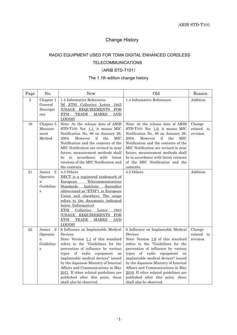
Page No. New Old Reason 2 Chapter 1
General Descriptions
1.4 Informative References [9] ETSI Collective Letter 1943 (USAGE REQUIREMENTS FOR ETSI TRADE MARKS AND LOGOS)
1.4 Informative References Addition
16 Chapter 5 Measurement Method
Note: At the release date of ARIB STD-T101 Ver. 1.1, it means MIC Notification No, 88 on January 26, 2004. However if the MIC Notification and the contents of the MIC Notification are revised in near future, measurement methods shall be in accordance with latest versions of the MIC Notification and the contents.
Note: At the release date of ARIB STD-T101 Ver. 1.0, it means MIC Notification No, 88 on January 26, 2004. However if the MIC Notification and the contents of the MIC Notification are revised in near future, measurement methods shall be in accordance with latest versions of the MIC Notification and the contents,
Change related to revision
21 Annex 2 Operation Guidelines
4.5 Others DECT is a registered trademark of European Telecommunications Standards Institute (hereafter abbreviated as "ETSI"), in European Union and elsewhere. The usage refers to the documents indicated below. (Informative) ETSI Collective Letter 1943 (USAGE REQUIREMENTS FOR ETSI TRADE MARKS AND LOGOS)
4.5 Others Addition
22 Annex 2 Operation Guidelines
6 Influence on Implantable Medical Devices Note: Version 1.1 of this standard refers to the "Guidelines for the prevention of influence by various types of radio equipment on implantable medical devices" issued by the Japanese Ministry of Internal Affairs and Communications in May 2011. If other related guidelines are published after this point, these shall also be observed.
6 Influence on Implantable Medical Devices Note: Version 1.0 of this standard refers to the "Guidelines for the prevention of influence by various types of radio equipment on implantable medical devices" issued by the Japanese Ministry of Internal Affairs and Communications in May 2010. If other related guidelines are published after this point, these shall also be observed.
Change related to revision

ARIB STD-T101
-2-
The 1.1th E2 edition change history
Page No. New Old Reason 10 Chapter 3
Technical Requirements for Radio Equipment
3.2 Transmitter (3) Permissible values for unwanted emission intensity b) Permissible value for unwanted emission intensity in out-band range (except for frequency bands listed in c)
(a) Higher than 864 kHz to 1,228 kHz from center frequency: Average power -5.6 dBm or less in any 192 kHz band
(b) Higher than 1,228 kHz to 2,592 kHz from center frequency: Average power -9.5 dBm or less in any 1 MHz band
(c) Higher than 2,592 kHz to 4,320 kHz from center frequency: Average power -29.5 dBm or less in any 1 MHz band
3.2 Transmitter (3) Permissible values for unwanted emission intensity b) Permissible value for unwanted emission intensity in out-band range (except for frequency bands listed in c)
(a) Within 864 kHz to 1,228 kHz from center frequency: Average power -5.6 dBm or less in any 192 kHz band
(b) Within 1,228 kHz to 2,592 kHz from center frequency: Average power -9.5 dBm or less in any 1 MHz band
(c) Within 2,592 kHz to 4,320 kHz from center frequency:
Average power -29.5 dBm or less in any 1 MHz band
Correction
10 Chapter 3 Technical Requirements for Radio Equipment
3.2 Transmitter (3) Permissible values for unwanted emission intensity c) Permissible value for unwanted emission intensity in the frequency range between higher than 1,891.296 MHz and 1,893.146 MHz and between higher than 1,906.1 MHz and lower than 1,906.848 MHz
(a) Higher than 1,892.846 MHz to 1,893.146 MHz, or higher than 1,906.1 MHz to lower than 1,906.754 MHz: Average power -31 dBm or less in any 192 kHz
(b) Higher than 1,891.296 MHz to 1,892.846 MHz, or 1,906.754 MHz to lower than 1,906.848 MHz: Average power -36 dBm or less in any 192 kHz
3.2 Transmitter (3) Permissible values for unwanted emission intensity c) Permissible value for unwanted emission intensity in the frequency range between 1,891.296 MHz and 1,893.146 MHz and between 1,906.1 MHz and 1,906.848 MHz
(a) Average power -31 dBm or less in the range from 1,892.846 MHz to 1,893.146 MHz and from 1,906.1 MHz to 1,906.754 MHz
(b) Average power -36 dBm or less in the range from 1,891.296 MHz to 1,892.846 MHz and from 1,906.754 MHz to 1,906.848 MHz
Correction
12 Chapter 3 Technical Requirements for Radio Equipment
3.3 Receiver (1) Limit on Secondary Radiated Emissions, etc. Table 3-5 Limit on Secondary Radiated Emissions, etc. 1,893.5 MHz or higher to 1,906.1 MHz
3.3 Receiver (1) Limit on Secondary Radiated Emissions, etc. Table 3-5 Limit on Secondary Radiated Emissions, etc. 1,893.5 MHz or higher to lower than 1,906.1 MHz
Correction
12 Chapter 3 Technical Requirements for
3.3 Receiver (1) Limit on Secondary Radiated Emissions, etc. Table 3-5 Limit on Secondary
3.3 Receiver (1) Limit on Secondary Radiated Emissions, etc. Table 3-5 Limit on Secondary
Correction

ARIB STD-T101
-3-
Radio Equipment
Radiated Emissions, etc. 2 The mean power in the 30 kHz bandwidth in 420 frequencies which have added an integral multiple of 30 kHz to 1,893.515 MHz and 1,893.515 MHz in the range of 1,893.515 MHz to no greater than 1,906.085 MHz shall be a value not greater than 0.06 mW; provided that the mean power in the 30 kHz bandwidth shall be a value no greater than 250 nW for any continuous 2 among the said 420 frequencies.
Radiated Emissions, etc. 2 The mean power in the 30 kHz bandwidth in 420 frequencies which have added an integral multiple of 30 kHz to 1,893.515 MHz and 1,893.515 MHz in the range of 1,893.5.5 MHz to no greater than 1,906.085 MHz shall be a value not greater than 0.06 mW; provided that the mean power in the 30 kHz bandwidth shall be a value no greater than 250 nW for any continuous 2 among the said 420 frequencies.
12 Chapter 3 Technical Requirements for Radio Equipment
3.3 Receiver (1) Limit on Secondary Radiated Emissions, etc. Table 3-5 Limit on Secondary Radiated Emissions, etc. Higher than 1,906.1 MHz to lower than 12.75 GHz
3.3 Receiver (1) Limit on Secondary Radiated Emissions, etc. Table 3-5 Limit on Secondary Radiated Emissions, etc. 1,906.1 MHz or higher to lower than 12.75 GHz
Correction

ARIB STD-T101
-4-
The 1.2th edition change history
Page No. New Old Reason 15 Chapter 4
Systems Interoperability
4.2.3 Reporting of available carrier frequencies ETSI EN 300 175 Part 3 (Medium Access Control (MAC) layer), 7.2.4.3.9 Active carriers However, the carrier frequency assignment shall be as shown in Table 4-2. Table 4-2 Carrier Frequency Assignment
Bit position Carrier frequency
a36 1,902.528 MHza37 1,900.8 MHz a38 1,899.072 MHza39 1,897.344 MHza40 1,895.616 MHza41 - a42 - a43 - a44 - a45 -
4.2.3 Reporting of available carrier frequencies ETSI EN 300 175 Part 3 (Medium Access Control (MAC) layer), 7.2.4.3.9 Active carriers
Addition of Table 4-2 which complying with Japanese technical requirements
16 Chapter 5 Measurement Method
Note: At the release date of ARIB STD-T101 Ver. 1.2, it means MIC Notification No, 88 on January 26, 2004. However if the MIC Notification and the contents of the MIC Notification are revised in near future, measurement methods shall be in accordance with latest versions of the MIC Notification and the contents.
Note: At the release date of ARIB STD-T101 Ver. 1.1, it means MIC Notification No, 88 on January 26, 2004. However if the MIC Notification and the contents of the MIC Notification are revised in near future, measurement methods shall be in accordance with latest versions of the MIC Notification and the contents,
Change related to revision
22 Annex 2 Operation Guidelines
6 Influence on Implantable Medical Devices Note: Version 1.2 of this standard refers to the "Guidelines for the prevention of influence by various types of radio equipment on implantable medical devices" issued by the Japanese Ministry of Internal Affairs and Communications in May 2011. If other related guidelines are published after this point, these shall also be observed.
6 Influence on Implantable Medical Devices Note: Version 1.1 of this standard refers to the "Guidelines for the prevention of influence by various types of radio equipment on implantable medical devices" issued by the Japanese Ministry of Internal Affairs and Communications in May 2011. If other related guidelines are published after this point, these shall also be observed.
Change related to revision

ARIB STD-T101
-5-
The 1.3th edition change history
Page No. New Old Reason General
Notes
Unify expression
Foreword Unify expression
15-17 Chapter 4
Systems
Interopera
bility
4.2.2 RF carrier number 4.2.2.1 RF carrier numbering type Two kinds of RF carrier numbering types are used to show the RF carrier number. The system uses either. (1) Simplified numbering The system uses only basic RF carrier number which is in the set {0,1,2,3,4,5,6,7,8,9}. However the set {5,6,7,8,9} are reserved and not used. The RF carrier number assignment shall be as shown in Table 4-1. (This RF carrier numbering is Japan specific de facto standard due to the frequency allocation.) Table 4-1 RF carrier Number Assignment (2) ETSI Standard numbering ETSI EN 300 175 Part 2 (Physical Layer (PHL)) Annex F.2 The system uses an extended RF carrier number which is in the set {10,11,12, … ,63} in addition to the basic RF carrier number. This RF carrier numbering refer to the ETSI standard. The RF carrier number assignment shall be as shown in Table 4-2. Table 4-2 RF carrier Number Assignment 4.2.2.2 Reporting of the RF carrier numbering type ETSI EN 300 175 Part 3 (Medium Access Control (MAC) layer), 7.2.3.2.7 Extended RF carrier information available (Mc) The RF carrier numbering type in the system is classified by the “Extended RF carrier information available (Mc)” in the “Static system
4.2.2 Carrier frequency number ETSI EN 300 175 Part 2 (Physical Layer (PHL)) Annex F.2 The carrier frequency number allocation shall be as shown in Table 4-1. Table 4-1 Carrier Frequency Number Allocation
Information

ARIB STD-T101
-6-
information” message over the dummy bearer, and it shall be as shown in Table 4-3. Table 4-3 Extended RF carrier information available (Mc) 4.2.3 Reporting of available carrier frequencies ETSI EN 300 175 Part 3 (Medium Access Control (MAC) layer), 7.2.4.3.9 Active carriers However, the RF carrier frequency assignment shall be as shown in Table 4-4. Table 4-4 Carrier Frequency Assignment 4.2.4 Identification code (1) Identification code used by base unit radio equipment The RFPI (Radio Fixed Part Identity) specified in ETSI EN 300 175 Part 6 (Identities and addressing), 5 FP identities (2) Identification code used by radio equipment other than base unit The IPEI (International Portable Part Equipment Identity) specified in ETSI EN 300 175 Part 6 (Identities and addressing), 10 Equipment related identities
4.2.3 Reporting of available carrier frequencies ETSI EN 300 175 Part 3 (Medium Access Control (MAC) layer), 7.2.4.3.9 Active carriers However, the carrier frequency assignment shall be as shown in Table 4-2. Table 4-2 Carrier Frequency Assignment 4.2.4 Identification sign (1) Identification sign used by base unit radio equipment The RFPI (Radio Fixed Part Identity) specified in ETSI EN 300 175 Part 6 (Identities and addressing), 5 FP identities (2) Identification sign used by radio equipment other than base unit The IPEI (International Portable Part Equipment Identity) specified in ETSI EN 300 175 Part 6 (Identities and addressing), 10 Equipment related identities
18 Chapter 5
Measurem
ent
Method
Unify expression
24 Annex 2
Operation
Guidelines
6 Influence on Implantable Medical Devices
6 Influence on Implantable Medical Devices
Unify expression

ARIB STD-T101
-7-
The 2.0th edition change history
Page No. New Old Reason 4-9 Chapter 3
Technical
Requiremen
ts for Radio
Equipment
3.1 General
Conditions
(1) Operating frequency band Emissions of a frequency of 1,895.616 MHz or an integral multiple of 1,728 kHz added to 1,895.616 MHz in a range from 1,895.616 MHz to 1,904.256 MHz shall be used. (2) Emission class and use Table 3-1 Emission Class and Use
Frequency 1,895.616 MHz, 1,897.344 MHz, 1,899.072 MHz, 1,900.8 MHz, 1,902.528 MHz, 1,904.256 MHz
(3),(4),(5) (omitted) (deleted) (6) Frame configuration (7) Cabinet The radio equipment shall be contained within a single enclosure that is not easy to open excluding antenna. (8) Carrier sense a) When preparing to emit a radio wave, emission in the respective channel shall be enabled only if the received power of radio waves from any radio station other than the communication pair in the channel to be used for emission and the corresponding channel to be used for
(1) Operating frequency band Emissions of a frequency of 1,895.616 MHz or an integral multiple of 1,728 kHz added to 1,895.616 MHz in a range from 1,895.616 MHz to 1,902.528 MHz shall be used. (2) Emission class and use Table 3-1 Emission Class and Use
Frequency1,895.616 MHz,1,897.344 MHz, 1,899.072 MHz, 1,900.8 MHz, 1,902.528 MHz,
(3),(4),(5) (omitted) (6) The number of multiplexed channels, the number of channels per carrier (7) Frame configuration (8) Cabinet The radio equipment shall be contained within a single enclosure that is not easy to open. However, regarding power supply equipment, mouthpiece, and ear receiver, as well as equipment listed below, this provision does not apply. a) Radio equipment used in handset Equipment other than RF section and modulator section (excluding antenna and related parts) b) Radio equipment other than listed in a) (a) Displays indicating the operation status of the transmitter equipment and receiver equipment, and other parts also are subject to the same requirement. (b) Operation control parts used for performing communication (c) Volume control parts and related parts (9) Carrier sense a) When preparing to emit a radio wave, emission in the respective channel shall be enabled only if the received power of radio waves from any radio station other than the communication pair in the channel to be used for emission and the corresponding channel to be used for
Changes due to systemic revision

ARIB STD-T101
-8-
reception is -62 dBm or lower for at least 2 consecutive frames. b) The measured level of radio waves received from any radio station other than the communication pair in the channel to be used for emission and the corresponding channel to be used for reception for at least 2 consecutive frames (hereafter called the "interference level") shall be evaluated using two carrier sense levels called Level 1 and Level 2. The carrier sense level values are given in Table 3-2. Table 3-3 Carrier Groups
Carrier Group 1
1,895.616 MHz, 1,897.344 MHz, 1,902.528 MHz, 1,904.256 MHz
Carrier Group 2
1,899.072 MHz, 1,900.8 MHz
c),d) (omitted) e) The reception power when measuring the interference level shall be the maximum value for the frequency to be used for transmission and the occupied time duration. f),g) (omitted) (9) Protection of TDMA narrow-band digital cordless telecommunications a) When the base unit prepares to emit a radio wave at 1,899.072 MHz, or 1,900.8 MHz, emission shall only be enabled if the received power in the TDMA narrow-band digital cordless telephone control channel (which is emitted at 1,898.45 MHz or 1,900.25 MHz) is -82 dBm or lower. However, if the radiated power is 1 mW or less at 1,899.072 MHz or the radiated power is 0.3 mW or less at 1,900.8 MHz, the radio wave emission would be allowed unless compensating for the decrease in radiated power with the antenna gain. b) If received power of the TDMA narrow-band digital cordless telephone control channel at the 1,899.072 MHz and 1,900.8 MHz frequency is continuously at -82 dBm or lower for at least 300 ms, the base unit shall regard it as absence of that control channel. If received power exceeds -82 dBm, this shall regard it as presence of a radio wave for the
reception is -62 dBm or lower for at least 2 consecutive valid frames. b) The measured level of radio waves received from any radio station other than the communication pair in the channel to be used for emission and the corresponding channel to be used for reception for at least 2 consecutive valid frames (hereafter called the "interference level") shall be evaluated using two carrier sense levels called Level 1 and Level 2. The carrier sense level values are given in Table 3-2. Table 3-3 Carrier Groups
Carrier Group 1
1,895.616 MHz, 1,897.344 MHz, 1,902.528 MHz,
Carrier Group 2
1,899.072 MHz, 1,900.8 MHz
c),d) (omitted) e) The reception power when measuring the interference level shall be the peak value for the frequency to be used for transmission and the occupied time duration. f),g) (omitted) (10) Protection of TDMA narrow-band digital cordless telecommunications a) When the base unit prepares to emit a radio wave at 1,897.344 MHz, 1,899.072 MHz, or 1,900.8 MHz, emission shall only be enabled if the received power in the TDMA narrow-band digital cordless telephone control channel is -82 dBm or lower. b) When the base unit prepares to emit an radio wave at 1,897.344 MHz, 1,899.072 MHz, or 1,900.8 MHz, if received power of the TDMA narrow-band digital cordless telephone control channel at the 1,899.072 MHz and 1,900.8 MHz frequency is continuously at -82 dBm or lower for at least 300 ms, this shall be taken as absence of a radio wave

ARIB STD-T101
-9-
TDMA narrow-band digital cordless telephone control channel. c) When the base unit has determined that there is a radio wave of the TDMA narrow-band digital cordless telephone control channel, it shall report that new radio wave emission at 1,899.072 MHz or 1,900.8 MHz is restricted. If the respective frequency is already being used for communication, continuous radio wave emission for this communication shall be allowed. d) (omitted) e) If the base unit cannot determine the presence or absence of a radio wave due to the TDMA narrow-band digital cordless telephone control channel immediately before starting radio wave emission at 1,899.072 MHz or 1,900.8 MHz the presence/absence evaluation shall be made according to the following method. (a) The base unit shall use the latest information about the presence/absence of a radio wave due to the TDMA narrow-band digital cordless telephone control channel at the time of power-up, system reset, and during operation as a basis for evaluation. (b) The base unit shall evaluate the presence/absence of a radio wave due to the TDMA narrow-band digital cordless telephone control channel at least once every hour. (c) The base unit, when evaluating the presence/absence of a radio wave due to the TDMA narrow-band digital cordless telephone control channel at the time of power-up or a system reset, shall take evaluation failure due to overlapping radio waves from other radio stations as equivalent to the presence of a radio wave in the TDMA narrow-band digital cordless
in that channel. If received power exceeds -82 dBm, this shall be taken as presence of a radio wave in that channel. Radio wave emission shall be enabled if the result is that there is no radio wave in the TDMA narrow-band digital cordless telephone control channel. c) When the base unit has determined that there is a radio wave in the TDMA narrow-band digital cordless telephone control channel, it shall report that new radio wave emission at 1,897.344 MHz, 1,899.072 MHz, or 1,900.8MHz is not possible and shall not begin radio wave emission at these frequencies. If the respective frequency is already being used for communication, continuous radio wave emission for this communication shall be allowed. d) (omitted) e) If the base unit cannot determine the presence or absence of a radio wave in the TDMA narrow-band digital cordless telephone control channel immediately before starting radio wave emission at 1,897.344 MHz, 1,899.072 MHz, or 1,900.8MHz, the presence/absence evaluation shall be made according to the following method. (a) The base unit shall use the latest information about the presence/absence of a radio wave in the TDMA narrow-band digital cordless telephone control channel at the time of power-up, system reset, and during operation as a basis for evaluation. (b) The base unit shall evaluate the presence/absence of a radio wave due to the TDMA narrow-band digital cordless telephone control channel at least once every hour. (c) The base unit, when evaluating the presence/absence of a radio wave in the TDMA narrow-band digital cordless telephone control channel at the time of power-up or a system reset, shall take evaluation failure due to overlapping radio waves from other radio stations as equivalent to the presence of a radio wave in the TDMA narrow-band digital cordless

ARIB STD-T101
-10-
telephone control channel. (d) The base unit, when evaluating the presence/absence of a radio wave due to the TDMA narrow-band digital cordless telephone control channel during operation, shall continue to use the previous evaluation result if evaluation fails due to overlapping radio waves from other radio stations, or due to overlapping with the channel or slot used by the radio station itself. f) When the handset intends to emit a radio wave at 1,899.072 MHz or 1,900.8 MHz, emission shall be enabled only when the use of those carrier frequencies are not restricted. However, if the radiated power is 1 mW or less at 1,899.072 MHz or the radiated power is 0.3 mW or less at 1,900.8 MHz, the radio wave emission would be allowed unless compensating for the decrease in radiated power with the antenna gain. g) When the base unit has determined that there is a radio wave in the TDMA narrow-band digital cordless telephone control channel, it shall comply with the following conditions in the case of emitting a radio wave that burst length shorter than 0.3125 ms as a control channel.(a) Emissions of a frequency of 1,895.616 MHz or 1,902.528 MHz shall be used. (b) Emissions of a frequency of 1,897.344 MHz or 1,904.256 MHz can be used only when frequencies of 1,895.616 MHz and 1,902.528 MHz cannot be used. (c) When using the 1,897.344 MHz or 1,904.256 MHz frequency, the same channel shall not be occupied for more than 1 hour. (*) (*) When continuously radiating radio waves with a burst length shorter than 0.3125 ms at frequencies other than 1,895.616 MHz or 1,902.528 MHz, it is desirable to design or operate so that it will be used for a short time. (10) Interference avoidance (11) Failure
telephone control channel. (d) The base unit, when evaluating the presence/absence of a radio wave in the TDMA narrow-band digital cordless telephone control channel during operation, shall continue to use the previous evaluation result if evaluation fails due to overlapping radio waves from other radio stations, or due to overlapping with the channel or slot used by the radio station itself. (11) Interference avoidance (12) Failure

ARIB STD-T101
-11-
10-13 Chapter 3
Technical
Requiremen
ts for Radio
Equipment
3.2 Transmitter
(1)-(8) (omitted) (9) Antenna power The antenna power shall be 240 mW or less. The antenna power is the average power during the burst transmission.(10) Absolute gain of the antenna The absolute gain of the antenna shall be 4 dB or less. However, when the effective radiated power is equal to or less than the value obtained by applying an antenna power of 240 mW to the antenna with its absolute gain being 4 dB, the shortage shall be compensated for by the gain of the antenna. (11) Control of the antenna power In the case of equipment having a function of automatically controlling the antenna power so as to be the minimum necessary, it can control the antenna power by measuring the received power of the radio wave from the other radio station of the communication. (12) Tolerance of Specific Absorption Rate in human body (excluding head and both hands) Specific Absorption Rate (defined as a numerical value divided the electromagnetic energy absorption into 10g of tissue within 6 minutes by 10 g then again by 6 minutes) of human exposure (excluding head and both hands) to radio wave (multiple radio waves in the case of combining with other transmitting devices in the same cabinet) from radio equipment shall be 2 W/kg (4 W/kg in case of limb). However, this measurement of SAR may be omitted for the following radio equipment as being deemed to comply with this provision. a) Radio equipment with 20 mW or less of the average transmission power (total transmission power in case of multiple radio transmitters). b) The distance between the radio equipment with the radiating antenna and the human body (excluding the head and both hands) is exceeding 20 cm. c) Radio equipment certified by the technical standard conformity
(1)-(8) (omitted) (9) Antenna power The antenna power shall be 10 mW or lower in terms of the mean power per channel. (10) Absolute gain of the antenna The absolute gain of the antenna shall be 4 dB or less. However, when the effective radiated power is equal to or less than the value obtained by applying an antenna power of 10 mW to the antenna with its absolute gain being 4 dB, the shortage shall be compensated for by the gain of the antenna.
Changes due to systemic revision

ARIB STD-T101
-12-
certificate etc. by August 31, 2018 according to the old technical standards prior to October 1, 2017. The average transmission power emitted by the radio equipment refers to the time average power in the case of continuous burst transmission using the maximum number of channels (excluding at the time of channel switching) that can be taken in the normal operation. (13) Tolerance of Specific Absorption Rate in human head Specific Absorption Rate of human head exposure to radio wave (multiple radio waves in the case of combining with other transmitting devices in the same cabinet) from radio equipment shall be 2 W/kg. However, this measurement of SAR may be omitted for the following radio equipment as being deemed to comply with this provision. a) Radio equipment with 20 mW or less of the average transmission power (total transmission power in case of multiple radio transmitters). b) Radio equipment which is no other than the portable use. c) Radio equipment which is not used in close proximity to the human head.d) Radio equipment certified by the technical standard conformity certificate etc. by August 31, 2018 according to the old technical standards prior to October 1, 2017.
14-15 Chapter 3
Technical
Requiremen
ts for Radio
Equipment
3.4 Handset
(1) (omitted) (2) Radio communication which is performed between two or more handsets (limited to the handsets which don't memorize an identification sign of the same base unit) a),b),c) (omitted) (deleted) (deleted)
(1) (omitted) (2) Radio communication which is performed between two or more handsets (limited to the handsets which don't memorize an identification sign of the same base unit) a),b),c) (omitted) d) The maximum number of simultaneously usable channels shall be 1 except when the channel is switched. (3) Maximum number of simultaneously usable channels
Changes due to systemic revision

ARIB STD-T101
-13-
16-20 Chapter 4
Systems
Interoperabi
lity
4.2
Transmissio
n Protocols
etc.
4.2.2 RF carrier number 4.2.2.1 RF carrier numbering type (1) Simplified numbering The system uses only basic RF carrier number which is in the set {0,1,2,3,4,5,6,7,8,9}. However the set {5,6,7,8} are reserved and not used. The RF carrier number assignment shall be as shown in Table 4-1. (This RF carrier numbering is Japan specific de facto standard due to the frequency allocation.) Table 4-1 RF carrier Number Assignment
RF carrier number
RF carrier frequency
4 1,895.616 MHz3 1,897.344 MHz2 1,899.072 MHz1 1,900.8 MHz0 1,902.528 MHz9 1,904.256 MHz
(2) ETSI Standard numbering Table 4-2 RF carrier Number Assignment
RF carrier number
RF band number
RF carrier frequency
1 - 1,895.616 MHz
0 - 1,897.344 MHz
10 00001 1,899.072 MHz
11 00001 1,900.8 MHz
12 00001 1,902.528 MHz
13 00001 1,904.256 MHz
4.2.3 Reporting of available carrier frequencies ETSI EN 300 175 Part 3 (Medium Access Control (MAC) layer), 7.2.3.2.8 RF carriers available (RF-cars) and 7.2.3.3 Extended RF carrier information part 1 (1) Simplified numbering Available RF carrier numbers are indicated in the set of “RF carriers available (RF-cars)” field in the “Static system information” message over the dummy bearer. “RF carriers available (RF-cars)” shall be as shown in Table 4-4.
4.2.2 RF carrier number 4.2.2.1 RF carrier numbering type (1) Simplified numbering The system uses only basic RF carrier number which is in the set {0,1,2,3,4,5,6,7,8,9}. However the set {5,6,7,8,9} are reserved and not used. The RF carrier number assignment shall be as shown in Table 4-1. (This RF carrier numbering is Japan specific de facto standard due to the frequency allocation.) Table 4-1 RF carrier Number Assignment
RF carrier number
RF carrier frequency
4 1,895.616 MHz 3 1,897.344 MHz 2 1,899.072 MHz 1 1,900.8 MHz 0 1,902.528 MHz
(2) ETSI Standard numbering Table 4-2 RF carrier Number Assignment
RF carrier number
RF band number
RF carrier frequency
1 - 1,895.616 MHz
0 - 1,897.344 MHz
10 00001 1,899.072 MHz
11 00001 1,900.8 MHz
12 00001 1,902.528 MHz
4.2.3 Reporting of available carrier frequencies
Changes due to systemic revision

ARIB STD-T101
-14-
Table 4-4 RF carriers available (RF-cars)
BitMeaning ax, 22≦
x≦31 0 Carrier number (x-22)
is not available 1 Carrier number (x-22)
is available (2) ETSI Standard numbering The available RF carrier numbers for the basic carriers can be same as the case of the simplified numbering. And the available RF carrier numbers for the extended carriers are indicated in the set of “Extended RF carriers available (Extended RF-cars)” field in the “Extended RF carrier information part 1” message over the dummy bearer. “Extended RF carriers available (Extended RF-cars)” shall be as shown in Table 4-5. Table 4-5 Extended RF carriers available (Extended RF-cars)
BitMeaning ax, 12≦
x≦34 0 Extended carrier
number (x-2) is not available
1 Extended carrier number (x-2) is available
4.2.4 Reporting of the carrier frequencies with restriction on use ETSI EN 300 175 Part 3 (Medium Access Control (MAC) layer), 7.2.4.3.9 Active carriers Even at the available carrier frequency, in the case of imposing restrictions on the use of the carrier frequency, the target carrier frequencies would be notified by the base unit or the repeater. This target with usage restriction is indicated in the set of “active carriers” of “MAC Layer information” field in the “short page” message or “zero length page” message. The RF carrier frequency and meaning assigned to each bit are shown in Table 4-6.
ETSI EN 300 175 Part 3 (Medium Access Control (MAC) layer), 7.2.4.3.9 Active carriers However, the RF carrier frequency assignment shall be as shown in Table 4-4.

ARIB STD-T101
-15-
Table 4-6 Carrier Frequency Assignment and meaning of each bitBits RF carrier
frequency Meaning
a36 1,902.528MHz
0/1=cannot be used/can be used unconditionally
a37 1,900.8 MHz
0/1=can be used conditionally (*1)/
can be used unconditionally
a38 1,899.072
MHz
0/1=can be used conditionally (*1)/
can be used unconditionally
a39 1,897.344MHz
0/1=cannot be used/can be used unconditionally
a40 1,895.616MHz
0/1=cannot be used/can be used unconditionally
a41 - -a42 - -a43 - -a44 - -a45 1,904.256
MHz 0/1=cannot be
used/can be used unconditionally
(*1) For use condition, see 3.1(9) f)4.2.5 Identification code (omitted)
Table 4-4 Carrier Frequency Assignment
Bits
RF carrier frequency
a36 1,902.528MHz a37 1,900.8MHz a38 1,899.072MHz a39 1,897.344MHz a40 1,895.616MHz a41 -a42 -a43 -a44 -a45 -
4.2.4 Identification code (omitted)
21 Annex 1
Test Items
Associated
with
Specified
Radio
Equipment
(1) Transmitter Frequency Occupied frequency bandwidth Spurious emission or unwanted emission intensity Antenna power Specific Absorption Rate (SAR)* Adjacent channel leakage power or out-band leakage power Power when carrier is not being transmitted Transmission rate * It is limited to the applied to ORE Article 14-2.1 or 14-2.2 (2) Receiver (omitted) (3) Other equipment Carrier sense function
(1) Transmitter Frequency Occupied frequency bandwidth Spurious emission or unwanted emission intensity Antenna power Adjacent channel leakage power or out-band leakage power Power when carrier is not being transmitted Transmission rate (2) Receiver (omitted)
Changes due to systemic revision
27 Annex 3
Compliance
of radiation
protection
(add new annex)
Changes due to systemic revision


To: Secretariat of Standard Assembly Meeting of the Association of Radio Industries and Businesses FAX: +81-3-3592-1103 E-mail: [email protected] Nittochi Bldg. 11F, 1-4-1 Kasumigaseki, Chiyoda-ku, Tokyo 100-0013, Japan
Communication Note of ARIB Standard-related Proposals, etc.
ARIB Standard Name (No.)
RADIO EQUIPMENT USED FOR TDMA DIGITAL ENHANCED CORDLESS TELECOMMUNICATIONS
(ARIB STD-T101)Sections to be completed by sender
Name: Date / / /
TEL: FAX: E-mail:
Company name Department name
Page / Section
(Please describe your proposal or present your questions or comments in concrete terms.)
(Response)
Sections to be completed by secretariat
Date of receipt / / /
Ref. No. -
Classification: Remarks
Please send your ARIB Standard-related question in this format. If you complete this form in English, please provide Japanese translation alongside the English.


RADIO EQUIPMENT USED FOR TDMA DIGITAL ENHANCED
CORDLESS TELECOMMUNICATIONS
ARIB STANDARD
ARIB STD-T101 Version 2.0
Version 1.0 March 28th 2011 Version 1.1 July 7th 2011 Version 1.2 December 18th 2012 Version 1.3 July 31st 2014 Version 2.0 January 22nd 2018
Published by
Association of Radio Industries and Businesses
Nittochi Bldg. 11F, 1-4-1 Kasumigaseki, Chiyoda-ku, Tokyo 100-0013,Japan
TEL: +81-3-5510-8590 FAX: +81-3-3592-1103
Printed in Japan
All rights reserved