radio equipment - mv ross revengerc/1 one- kilowatt am transmitter, type bta -1s excellent frequency...
TRANSCRIPT

Broadcast Systems
Radio Equipment
AM Transmitters FM Transmitters Exciters, Monitors STL, Remote Control Transmission Line Antennas, Towers
www.americanradiohistory.com


Roil
Contents
AM Transmitters One -Kilowatt Transmitter, Type BTA -1S RA.1011A One -Kilowatt Transmitter, Type BTA -1N1 RA.1021A Five -Kilowatt Transmitter, Type BTA -5L1 RA.1031A Ten -Kilowatt Transmitter, Type BTA -10L1 RA.1041A Fifty -Kilowatt Transmitter, Type BTA -50J RA.1061A 100 -Kilowatt Transmitter, Type BTA -100J RA.1071A 200 -Kilowatt Transmitter, Type BTA -200J RA.1071A
AM Monitors Modulation and Frequency Monitor, BW -50 RA.1111A RF Amplifier, Type BW -60 RA.1111A
FM Transmitters FM Exciter System, Type BTE -15A RA.2011A Ten Watt Educational Transmitter, BTE -10AT RA.2011A One -Kilowatt Transmitter, Type BTF -1E2 RA.2021A Two -Kilowatt Transmitter, Type BTF -1 +1E2 RA.2021A Two -Kilowatt Transmitter, Type BTF -1/1E2 RA.2021A Three -Kilowatt Transmitter, Type BTF -3E1 RA.2031A Six -Kilowatt Transmitter, Type BTF -3 +3E1 RA.2031A Three -Kilowatt Dual Transmitter, BTF -3/3E1 RA.2031A Five -Kilowatt Economy Transmitter, BTF -5E2 RA.2037A Five -Kilowatt Dual Transmitter, BTF -5E1 RA.2041A Ten -Kilowatt Dual Transmitter, BTF -5 +5E1 .. RA.2041A Five -Kilowatt Dual Transmitter, BTF -5/5E1 ....RA.2041A Ten -Kilowatt Transmitter, Type BTF -10E1 .. RA.2051A Twenty -Kilowatt Transmitter, BTF- 10 +10E1 RA.2051A Ten -Kilowatt Dual Transmitter, BTF- 10/10E1 RA.2051A Twenty -Kilowatt Transmitter, Type BTF -20E1 .. RA.2061A Forty- Kilowatt Transmitter, Type BTF -40E1 . RA.2071A
FM Monitors Frequency and Modulation Monitor, BW -75A RA.2111A Stereo Freq. and Mod. Monitor, BW -85A RA.2111A SCA Freq. and Mod. Monitor, BW -95A RA.2111A RF Amplifier, Type BW -100 RA.2111A
RA. 100
About This Catalog
This is one of several catalogs published by RCA Broadcast Systems Department. It describes products that serve the transmitter and antenna portions of the radio -broadcast plant.
For the audio portion of the plant, RCA publishes a companion catalog that describes microphones; control consoles; automatic program equipment; intercom/ interphone gear; amplifiers and signal processors; racks, cabinets, furniture, rack equipment; turntables and tone arms; cartridge and reel tape equipment; loud- speakers and accessories and audio test equipment.
For TV broadcasting, companion catalogs describe camera equipment; terminal and switching gear; UHF- and VHF -TV transmitters, transmission line, towers and antennas.
These catalogs are available at RCA Regional Offices (see list, next page). Each office is staffed by a sales representative with broad experience in the broadcast business. He can help you plan your equipment facilities and suppy the information you need.
Remote Control Equipment Sixty- Function Remote Control, BTR -30A1 RA.3011A Thirty- Function Remote Control, BTR -15B RA.3021A Extension Control /Metering Panel, BTC -2 RA.3031A Remote Control Accessories RA.3051A Automatic Logging Equipment RA.3061A
Remote Program Pickup and STL Equipment RPL and STL Equipment (Radio) RA.4011A
Transmission Line Equipment Rigid and Flexible Transmission Line .... RA.5011A Transmission Line Hangers RA.5021A Transmission Line Pressurization Equipment RA.5031A Transmission Line Co -Ax Switches RA.5041A
AM Antenna Equipment Towers for AM or FM RA.60118 AM Tuning Units, 250, 1000W RA.6111A AM Antenna Phasing Equipment RA.6211A Accessories for Antennas RA.6311A Antenna Monitors, Type AM -19 (204), PM -19 RA.6411A Field- Strength Meters RA.6511A
FM Antenna Equipment Towers for AM or FM RA.6011B Antenna, Type BFC- RA.7011A Antenna, Type BFG- RA.7111A Antenna, Type BFH- RA.7211A Antenna, Type BFI- RA.7311A Horizontally Polarized Antenna, Type BFA- RA.7511A Multiple- Station Antennas, BFD -, BFE -, BFF- RA.7611A RF Loads and Wattmeters RA.7711A Tower Isolators, Types BAF -15A, -16A RA.7811 A Antenna Ice Detector, Rosemount RA.7911A Thermostatic Sleetmelter Control RA.7921A
www.americanradiohistory.com

RCA
Atlanta, Ga. 30329 14 Executive Park Dr., N.E.
404- 634 -6131
Austin, Tex. 78758 Northwest Office Park Bldg. 8330 Burnet Rd., Suite 134
512- 451 -2500
Birmingham, Ala. 35223 Office Park Bldg. #10 Office Park Circle 205- 871 -1155
Boston Area: Wellesley, Mass. 02181 Wellesley Office Park 617- 237 -6050
Camden, N. J. 08102 Front & Cooper Sts. 609 -963 -8000
Charlotte, N. C. 28210 6230 Fairview Rd., Suite 104
704- 366 -0626
Chicago, III. 60606 Gateway lI Bldg., Suite 1400
120 S. Riverside Plaza 312- 782 -0700
Cincinnati, O. 45231
11430 Hamilton Ave. 513 -825 -1550
Dallas, Tex. 75247 RCA Center 8700 Stemmons Freeway 214- 638 -6200
Denver, Colo. 80211
2701 Alcott St., Suite 384 303 -433 -8484
Detroit: Southfield, Mich. 48075 24333 Southfield Rd., Suite 209 313 -357 -0080
Hollywood, Calif. 90028 RCA Corp., Suite 531
6363 Sunset Blvd. 213- 461 -9171
Jacksonville, Fla. 32207 2747 Art Museum Dr. Suite 5
904 -398 -4588
Kansas City Area: Overland Park, Kans. 66207 5750 West 95th St., Suite 111
913 -642 -3185, 6, 7
Regional Offices (Subject to change without notice)
Pittsburgh, Pa. Area: McMurray, Pa. 15317 761 N. Washington Blvd. 412 -941 -5570
Minneapolis, Minn. 55416 4522 Excelsior Blvd. 612 -920 -6395, 6
New York, N. Y. 10036 1133 Avenue of the Americas, 5th Floor 212 -586 -3000
San Francisco, Calif. 94102 420 Taylor St., Suite 401 -408 415- 441 -2200
St. Louis, Mo. 63105 7701 Forsyth Blvd., Suite 455 314- 862 -3660
Seattle. Wash. 98119 408 Second Ave., W.
206 -285 -2375
Washington, D. C. Area: Arlington, Va. 22209 1901 North Moore St. 703- 558 -4212
West Palm Beach, Fla. 33403 Palm Beach Gardens, Bldg. 110
3900 RCA Blvd. 305- 622 -1100
RCA International Marketing Subsidiaries (Subject to change without notice)
Argentina Buenos Aires RCA International Limited Calle Paroissien 3960 Telephone: 70 -4171
Australia 2113 North Ryde, N.S.W. RCA Limited 11 Khartoum Road Telephone: 888 -5444
Australia 3121 Richmond, Victoria RCA Limited 2 -4 Stephenson Street Telephone: 42 -4586
Brazil Rio de Janeiro -GB RCA Telesistemas Ltda. Rua Correa Dutra, 126 -4And Telephone: 245 -9209
Canada Ste. Anne de Bellevue, 810 P.Q. RCA Limited 21001 North Service Road Telephone: (514) 457 -9000
Toronto 15, Ontario RCA Limited 1450 Castlefield Avenue Telephone: (416) 651 -6550
Vancouver, British Columbia RCA Limited 2876 Rupert Street
at Grandview Highway Telephone: (604) 433 -0541
Hong Kong RCA International Limited 1927 Prince's Building Chater Road, G.P.O. 112 Telephone: H 234181
Mexico Mexico 17, D.F. RCA S.A. de C.V. Avenida Cuitlahuac 2519 Telephone: 5- 27 -60 -20 Ext. 104
Switzerland Geneva RCA International Marketing S.A. 118 rue du Rhone, CH 1204 Telephone: 35-82 -00
United Kingdom Jersey Isle RCA Jersey Limited Longueville Road, St. Saviour Telephone: CENTRAL 35355
www.americanradiohistory.com

RC/1
One- Kilowatt AM Transmitter, Type BTA -1S
Excellent frequency response, low distortion
Low operating costs
Circuit breaker overload protection
Positive peak modulation capability: 125%
catalog RA.1011 A (Replaces B.6004)
The RCA Type BTA -1S, 1- kilowatt AM Broadcast Transmitter is designed for reliability, outstanding fidelity, and economical operation. It provides a high quality amplitude modulated signal at any frequency in the 535 to 1620 kilohertz band and is capable of producing a max- imum of 1100 watts.
Highly perfected audio circuits together with a large, high -quality modulation transformer and reactor provide 125 -per- cent positive -peak modulation capability and unusually high fidelity sound. Stable, long -life tubes and solid -state devices have been used throughout the transmitter. Cir- cuit breakers, not fuses, provide complete overload protection.
Provision for remote control and sim- plified power cutback are reflected in the BTA -1S design. Front panel or re- mote control selection of any two power levels of 1000, 500 or 250 watts is avail- able. No unnecessarily complicated cir- cuitry or superfluous parts have been included and all components are easily accessible for maintenance and inspection.
www.americanradiohistory.com

RA 1011A
Unimpeded rear access to the transmitter is afforded by the full length door and the well laid out, vertical construction. Power supply components at bottom; r -f components at top.
Type BTA -1S Transmitter with outer and inner door open to display access- ibility to the tubes. Power amplifier and modulator tubes are near top while the lower chassis carries the audio -amplifier and intermediate stages.
www.americanradiohistory.com

Functional Design Improved functional design includes
RCA's new color combination. Square construction permits locating the trans- mitter against the wall, or it can be in- stalled against other equipment. The vertical construction makes it accessible from both front and rear for ease of maintenance. A single front panel tuning control provides simplified operation. Re- mote control provisions permit unat- tended operation of the transmitter.
Simplified Power Cutback The BTA -1S easily fits into operations
where power reduction at night is re- quired. For "day- night" operation an optional Power Cutback Kit may be in- corporated in the transmitter. By pressing a button on the front or at a remote panel, the transmitter can be cut back in power to either 500 or 250 watts. Ef- ficient operation at the low power levels is achieved by reducing the high voltage by primary taps on the plate transformer.
Complete Accessibility The entire transmitter is housed in a
single steel cabinet that is mounted on a sturdy welded steel base. Control com- ponents are conveniently located on the panel above the front door and all meters are at eye level. Easy access is provided by a hinged front door and two interlocked removable rear panels. Most BTA -1S com- ponents are mounted on a vertical center chassis. Tubes and overload relays are mounted on the front and the other com- ponents are mounted on the rear. Larger power components are mounted on the base.
Solid State Power Supplies Three power supplies are used: a low
voltage supply for plate and screen volt- ages of all low voltage tubes, a bias sup- ply for the modulator tubes, and a high voltage supply for the modulator and power amplifier tubes. All power supplies use silicon diodes which results in low power drain, cool operation and reliable performance. Automatic relays protect the transmitter against overload. These, in turn, are backed up with automatic circuit breakers. The design avoids the use of fuses anywhere in the unit.
Power Requirements The transmitter operates from a 208-
240 -volt, 50 /60- hertz, single -phase power source for the main power. In addition, the crystal heaters require 115 -volt power source.
Solid -State Oscillator and Buffer Stages
Adding an extra measure of transmit- ter stability, the BTA -1S combines its oscillator and buffer amplifier into a single, solid -state subassembly. The com- bination of transistorized electronics and temperature -controlled crystals make for an adjustment -free facility which, in turn, reduces routine maintenance. The oscil- lator is equipped with two temperature - controlled crystals arranged through a front -panel selector switch so that a "hot" spare is always at hand, even via remote control.
Simple, Straighforward Circuitry The buffer feeds a single 6146A driver
tube which in turn feeds the power am- plifier which consists of two 4 -400A tubes connected in parallel. Tetrodes have been utilized throughout the RF section of the transmitter reducing the required stages and the power consumption. Tetrodes also eliminate the need for neutralization.
The modulator comprises two 2E26 tubes in push -pull, resistance coupled to two 4-400A modulator tubes. The modu- lator tubes operate as a class AB, ampli-
RA.1011A
fier without grid current which results in an overall distortion of less than 2 per- cent up to 10,000 Hz.
Parallel /Redundant System The BTA -1S is available also as a par-
allel /redundant transmitter system. This system consists of two identical BTA -1S transmitters and a combiner. In the "parallel" mode, the twin one -kilowatt outputs are combined to provide two kilo- watts of power to the antenna system; in the "redundant" mode, the system operates one of the two transmitters as a hot standby while the other feeds the antenna system.
In either operational mode, the par- allel /redundant system assures greater on- air dependability. For example, an outage in one transmitter or the other automati- cally switches the troubled transmitter to a dummy load while the operable one feeds a full kilowatt to the antenna system. This action is the result of a special -design combiner with essentially zero insertion loss. Further details of the BTA -1S par- allel /redundant transmitter system are available from Aural Broadcast Equipment Marketing, RCA Building 2 -5, Camden, N. J. 08102, U.S.A.
SOLID- STATE OSCILLATOR AND
BUFFER
FIRST AUDIO
(2) 2E26 L SOLID - STATE
L. V.
SUPPLY
IPA 61464
MODULATOR (2) 4 -400A
POWER AMPLIFIER
(2) 4 -400A
SOLID - STATE BIAS
SUPPLY
SOLID - STATE
N V SUPPLY
v
Simplified block diagram of BTA -1S AM Transmitter.
www.americanradiohistory.com

RA.1011 A
Specifications Performance AF Input Impedance 150/600 ohms AF Input Level (100% modulation) +10 ±2 dBm AF Response:
50 -7500 Hz ±1 dB 30- 10,000 Hz ±1.5 dB
AF Distortion (95% modulation): 50- 10,000 Hz 2% 50- 12,000 Hz 3%
Noise (below 100% modulation) 60 dB Frequency Range 535 -1620 kHz Frequency Stability ±2 Hz
Type of Output Single ended Carrier Shift (0 -100% modulation) 3% Output Impedance 40 -250 ohms
Electrical RF Voltage (for frequency monitoring) 6/10 V rms 75 ohms RF Voltage (for modulation monitoring) 6/10 V rms 75 ohms Power Output (nominal) 1000 watts Power Output Capability 1100 watts Power Supply 208/240 volts Line Frequency 50/60 Hz Phase Single Power Consumption (Approx.):
0% modulation 2900 watts 100% modulation 3900 watts Average program modulation 3200 watts
Power Factor 90% Permissible combined line voltage variation
and regulation -5% Crystal Heater Power Supply 115 volts 50/60 Hz
Tube Complement 1 6146A Intermediate Power Amplifier 2 2E26 Audio Frequency Amplifier 2 4 -400A Modulator 2 4 -400A Power Amplifier
Mechanical Height 77" (1955 mm) Width 26" (660 mm) Depth 30" (762 mm)
Weight (net) 900 pounds (408 kg) ( approx.) Altitude Range 0.-5000 ft.* (0 -1254 m)
Ambient Operating Temperature -20 to 45 °C (- 4- 113 °F)
Shipping Data 1200 lbs (544 kg); 79 ff3 (2.23 ms)
Accessories Operating Spare Tube Kit ES- 560655
Recomended Minimum Spare Tube Kit ES- 560656
Frequency and Modulation Monitor, Type BW -50 M I- 560767
RF Amplifier (for BW -50) MI- 560762
Thirty- Function Remote Control, Type BTR -15 MI- 561150
Sixty- Function Remote Control, Type BTR -30 Ml- 561440
High -Altitude Blower Kit Ml- 34309 -8
Spare Crystal Unit, Type TMV -130 (Specify Freq.) MI -27493
RF Ammeters MI- 7157 -F Series
Remote RF Pickup Unit (less meter) MI- 27966 -B
Power Cutback Kit (Two Level) MI- 560657
Remote Power Adjust Kit MI- 560658
Oscillator -Buffer (Solid- State) Ml -27592
Ordering Information One- Kilowatt AM Transmitter, Type BTA -1S ES- 560650
250- or 500 -Watt AM Transmitter, Type BTA -1S (Specify power level) ES- 560947
'To 10,000 ft. (3048 m) with optional blower (MI- 34309-8).
www.americanradiohistory.com

RC/1
1 kW AM Broadcast Transmitter, Type BTA -1 N 1
Silicon power supplies
Low operating cost
Remote control provisions
Requires less than three square feet (0.258 square meters) of floor space
High speed magnetic circuit breaker protection - eliminates fuses
catalog RA.1021A (Replaces B.6002)
The Type BTA -1N1 is an amplitude - modulated transmitter of unique design that in every way leads broadcasting's modern trend to combine greater economy, simplicity and reliability in a single com- pact unit. A real performer, the Type BTA -1N1 uses fewer and less expensive components, incorporates simplified tuning, and easily produces 1000 watts maximum power output at any frequency between 535 and 1620 kilohertz.
Remote, unattended operation of the transmitter is a practical reality - en- hanced by simplified start -stop and power - control circuitry, remote metering and the long -term reliability of semiconductor power supplies. In the audio channel there are only two tubes, one transformer and a small modulation choke. Silicon rectifiers are used throughout.
www.americanradiohistory.com

RA.1021A
Lower front with access panel removed showing oversize blower, plate transformers and reactors.
The Type BTA -1N1 1 -kW Broadcast Transmitter is housed in a standard equip- ment rack that may be ganged with other racks. The transmitter is divided into three compartments: The upper com- partment is completely enclosed in alu- minum and contains the modulator, rf driver and power amplifier. The center compartment contains an oscillator/buffer assembly, bias supply, filter components for the high -voltage and intermediate high -voltage supplies and control curcuit. The lower compartment contains the high - voltage plate transformer, rectifier and blower. The rear panel of the upper two compartments is removable and both front and rear panels of the lower com- partments are removable to allow com- plete access to all components. The blower intake is thru a filter in the lower rear, thru the compartment containing the high -voltage plate transformer and rec- tifier, thus providing ample cooling.
Simplified, Reliable Circuits Simplicity of the Type BTA -1N1 trans-
mitter circuitry is shown by the block diagram. In the rf section, carrier fre- quency generated by the pentode section of a Type 6AX8 crystal oscillator is first amplified by a broadband tuned Type 6AX8 buffer using only the pentode sec- tion of the tube. The signal is then fed to a Type 7094 single -ended, Class C stage which drives an air -cooled 3X3000F1 triode operating with fixed bias as a Class AB1 power amplifier. The PA output circuit is broadband neutralized and in- cludes a harmonic trap which is adjustable from the front panel. Both the rf driver, which is the plate -modulated stage, and the power amplifier are tuned from the front panel by variable capacitors. Rf voltage for frequency monitoring is de- rived from the Type 6AX8 crystal oscil- lator and fed to the frequency monitor through the triode section of the tube. An rf sample for the modulation monitor is obtained from the low tap on the PA tank coil which also serves as a discharge path for static charges in the antenna circuit.
Audio is fed through a 150 /600 -ohm line input transformer and amplified by the triode section of a Type 6AX8 tube (pentode section utilized as rf buffer). This triode is resistance coupled to a Type 7094 Class A modulator which is choke -coupled to the plate circuit of the rf driver stage.
www.americanradiohistory.com

Solid State Power Supplies A plate supply and bias supply each
utilizing silicon diodes, equalizing resistors and printed wiring furnish all the dc voltages needed for the transmitter. The plate transformer is center tapped to pro- vide plate voltage for the driver -modu- lator stages as well as regulated low voltage for the oscillator and buffer plates. Only two filament transformers are used in the transmitter.
Metering of all Stages Individual meters are provided for
reading PA plate voltage, PA plate cur- rent and rf output (optional). Remaining stages and circuits such as the oscillator, buffer, audio, and low voltage supplies, are monitored by a multimeter and selec- tor switch combination which, in addition, provides other readings (useful in initial
Rear oblique view showing radio fre- quency driver and power compartment.
RA.1021A
tune -up) such as the peak rf voltage at the grid and plate of the PA. There are also provisions for remote metering of PA plate voltage and current.
"Fail- Safe" Protection Transmitter circuits are fail -safe pro-
tected by high -speed magnetic circuit breakers. A latching relay and an optional motor -driven power raise /lower control permits convenient remote control of the transmitter. Remote on -off switching is by a single control. This is made possible by interlocking of the bias and plate supplies, a feature which also prevents spurious overloads as a result of any brief power interruptions that may occur.
Ease of Tuning Built -in facilities reduce the tuning and
loading of the linear amplifier to a simple, three -step procedure which is performed at the control panel of the transmitter without need for accessory test equipment of any kind. Once initial adjustments are made, the transmitter can be operated over long periods of time with only the infrequent "touch -up" tuning required by any transmitter. Modulator circuits ordi- narily require no adjustment.
XTAL
Type BTA -1N1 Transmitter block diagram.
VI OSCILLATOR
V2 -A V3 V4
1/2
_1 vl
FREQ. MONITOR
AMPL. 1/2
6AX8
-.
6AX8
BUFFER 1/2 6AX8
V2-B AF AMPL.
1/2 6AX8
R-F DRIVER 7094
PA
3X3000F1
TO MODULATION
MONITOR
y
V5 MODULATOR
7094
TO FREQ. AUDIO MONITOR INPUT
www.americanradiohistory.com

RA.1021A
Specifications Electrical Frequency Range 535 to 1620 kHz
Power Output 500 to 1000 watts
Type of Output Single -ended
Output Impedance 40 to 250 ohms
AF Input Impedance _.._....150/600 ohms
AF Input Level (100% Modulation) +10 ±2 dBm
AF Response (50 to 7500 Hertz) ±1.5 dB
AF Distortion (90% Modulation)
Noise (Below 100% Modulation)
_...._.._ . 30/0
50 dB
Frequency Stability ..... .......... ..................... ±2 Hz
RF Voltage for Frequency Monitoring 10 volts, 75 ohms
RF Voltage for Modulation Monitoring 10 volts, 75 ohms
Total Harmonic Radiation -73 dB
Tube Complement
1 6AX8 (pentode) (triode)
1 6AX8 (pentode) (triode)
1 7094
1 7094
1 3X3000F1
Crystal Oscillator Frequency Monitor Amplifier
Buffer Amplifier Audio Amplifier
Amplifier Driver
Modulator
Power Amplifier
Power Requirements Transmitter:
Line 208 to 240 V., single phase, 50/60 Hz Combined Line Voltage Variation and Regulation ±5% Power Consumption (at 1000 watts) 4.5 kW (approx.) Power Factor 90% (approx.)
Cabinet Lighting and Crystal Heaters: Line 110 to 125 V., single phase, 50/60 Hz
Mechanical Dimensions (overall) 22" wide, 84" high, 18" deep
(560 mm, 2134 mm, 458 mm) Weight 625 lbs. (283 kg)
Maximum Altitude 7500 feet (2500 meters) Ambient Temperature Range.... -20° to +45 °C ( -4 to +113 °F) Air Intake 200 cf /m Heat Loss (0% Modulation) 3500 watts (200 BTU /min)
(12,000 BTU /hr) Accessories Set of Spare Tubes ES- 562202
Set of Spare Tubes (recommended spares) ES- 562201
RF Output Line Current Meter (range determined by antenna characteristics) MI- 7157 -H*
Remote Antenna Meter MI- 28037 -B* Crystal, Type TMV -130B MI -27493
Frequency and Modulation Monitor, Type BW -50 M I- 560767
Power Cutback Kit MI- 561301
Remote Power Adjust Kit MI- 561302
'Specify scale.
OrriPrinn !nfnrrpáfin-- One- Kilowatt AM Transmitter, Type BTA -1N1 ES- 562200
(Please specify operating frequency and transmission -line impedance.) (Includes harmonic filter and side panels.)
www.americanradiohistory.com

RCA 5 kW Ampliphase Transmitter, Type BTA -5 L 1
Low -distortion audio
Solid -state exciter /modulator Extra modulation capability
Designed for remote control
Only two tube types in entire unit
No modulation transformer
catalog RA.1031A (Replaces B.6005)
Offering superior audio quality, outstanding reliability and excellent efficiency, the BTA -5L1 is an Ampliphase transmitter for the AM- broadcast (medium -wave) band. The BTA -5L1 delivers 5 kW to the antenna transmission line. As a result of the Ampliphase system, the BTA -5L1 Transmitter offers extended audio -frequency response at distortion levels well below average perception at enviable operating economy and dependability. The BTA -5L1 is available also in dual -unit systems for parallel or redundant operation. In the "parallel" arrangement, the outputs of the two transmitters in the system are combined for a 10- kilowatt power output; in the "redundant" system, one transmitter serves the load while the second operates in hot standby mode.
A special feature of the parallel system is that, in the event of outage in one transmitter, the other trans- mitter delivers a full five -kilowatt output to the load. In the redundant arrangement, an outage in one transmitter or the other automatically connects the operable unit to the load.
www.americanradiohistory.com

RA.1031 A
Outstanding Audio Quality Of particular interest to broadcasters
who take pride in station "sound ", the BTA -5L1 Transmitter offers outstandingly good audio quality. One reason for this is that the Ampliphase system eliminates iron -core high -level modulation compo- nents - and their inherent distortions - without adding the instabilities of separate "carrier" and "peak" power amplifiers. Even on ordinary AM radios, the out- standing audio quality of an Ampliphase transmitter is immediately apparent.
Extended Frequency Response As evidence of the frequency- response
characteristics the BTA -5L1 offers, it can put 30 kHz on -the- air -at full power - without strain. At the low- frequency end of the spectrum, frequencies below 30 Hz go on- the -air at full level and low distor- tion. Transformer -equipped transmitters usually cut off below 50 Hz and above 15 kHz.
Extra Modulation Capability An advantage unique to the Ampli-
phase system is its capability for full modulation, even for extended periods, without overload. This is particularly important to stations programming music of high average level and low dynamics. Positive modulation peaks can go as high as 125 percent without transmitter over- load. Another unique feature in Ampli- phase is that it overmodulates without the "splatter" so common to other AM transmitter forms.
Provision for Spare Exciter /Modulator/ Regulator
For those who prefer redundant ex- citers, the BTA -5L1 Transmitter provides rack space for a spare exciter. Offered as an option, the spare exciter includes switch- ing gear for fast exciter substitution. A spare exciter is particularly valuable to the full -time station in that exciter main- tenance is independent of transmitter operation.
Ready for Remote Control Because the BTA -5L1 is built for the
modem broadcaster it is engineered with remote control in mind. This manifests itself in extra components, wiring and connections fully compatible with remote control equipment carrying the RCA trademark. As a result, operating a BTA - 5L1 via remote control requires investment only in control equipment and not in transmitter modification.
Two Tube Types Being entirely solid -state at power
levels below the IPA stage, the BTA -5L1 Transmitter uses a total of only four power tubes: two in each channel. Since
a®m
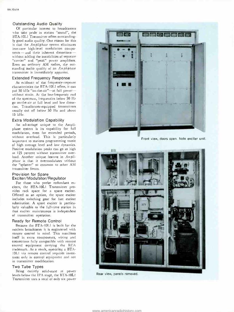
Front view, doors open. Note exciter unit.
Rear view, panels removed.
www.americanradiohistory.com

these are of only two types, spares inven- tory need only be two tubes: one of each type. This reduces capital investment in spares and periodic rotation.
No Modulation Transformer Using two identical R -F amplifier
chains, the BTA -5L1 Transmitter uses phase modulation, at a low level, in such a manner that two phase -modulated car- riers mix at the transmitter output to form an amplitude- modulated carrier. Since this system eliminates the modulation trans- former and "carrier- peak" amplifiers, it eliminates the most -troublesome stages. This reflects itself in transmitter depend- ability that virtually eliminates unsched- uled transmitter shutdown.
Faster Troubleshooting A feature unique to Ampliphase makes
routine repair easier. In a sense, a 5 -kW Ampliphase transmitter is two identical 2.5 -kW facilities in a single cabinet. Con- sequently, one amplifier chain is an ex- cellent troubleshooting model for the other. Because the operating parameters of the two class -C amplifiers (operating as CW stages) can be quickly compared, the trouble can be isolated easily. Then, it's a simple matter of component replace- ment.
Ceramic Insulated PA Tubes Ceramic power tubes have earned an
enviable reputation among broadcasters
wow
=11 1M21:=11M
O
RA.1031A
Ampliphase exciter unit. Completely solid- state, this unit is used in all RCA Am- pliphase transmitters. Available separately for use as a spare. See Accessories.
for dependability and long life. The tube types selected for the BTA -5L1 operate well below ratings to take full advantage of their performance capabilities and built -in expected life. This pays dividends in low transmitter -operating expenses.
Fully Self- Contained As the result of transistorization, the
entire transmitter- including the power supply -fits within a single cabinet that occupies less than 14 square feet (1.3 m2) of floor space (see floor plan). This, of course, frees plant area for other pro- ductive purposes; office, studio or storage.
Parallel /Redundant Systems The BTA -5LI transmitter is available
also as a parallel /redundant system. This arrangement uses two BTA -5L1 trans- mitters and a combiner. In the "parallel"
system, both transmitter outputs are com- bined to provide ten kilowatts to the load. Should one transmitter or the other have trouble, the operable transmitter continues to supply the load while the troubled transmitter is automatically switched from the antenna to a built -in dummy load.
In the redundant arrangement, one transmitter ordinarily feeds the antenna system while the other operates as a hot standby into a dummy load. Should the "air" unit fail, the system auto- matically connects the standby unit to the load and the troubled transmitter to the dummy load.
Further details are available from Aural Broadcast Marketing, RCA Build- ing 2 -2, Camden, N. J., 08102, U.S.A.
POWER CONTROL
CRYSTAL OSCILLATOR
EXCITER
PHASE DELAY
PULSE GENERATOR
SOLID STATE PULSE
AMPLIFIER
TRANSMITTER
DRIVER 8122
PA 3CX5000H3
COMBINING O OUTPUT NETWORK
PHASE MODULATOR
PULSE GENERATOR
SOLID STATE PULSE
AMPLIFIER
DRIVER 8122 3CX5000H5
Block diagram for BTA -5L1.
AUDIO INPUT
FEEDBACK DETECTOR
DRIVE REGULATOR
TO ANTENNA
www.americanradiohistory.com

RA.1031 A
WIRE
EXHAUST FAN ( NOT SUPPLIED )
DUCT TO POWER SOURCE
DOORS REMOVABLE
6 "(152)
TRANSMITTER
70" (1778)
22" ( 559) FRONT DOORS
PARENTHETICAL DIMENSIONS ARE IN MILLIMETERS
8 "(203)
OPTIONAL PHASING
EQUIPMENT J
BTA -5L1 Floor Plan. The transmitter is en- tirely self- contained.
Specifications Power Output (Nominal) 5,000 watts Power Output Capability 5,500 watts AF Input Impedance 150/600 ohms AF Input Level +10 ± 2 dBm AF Response ±1.5 dB 30- 15,000 Hz AF Distortion (95% Mod. 30- 10,000 Hz) 2.0% max. Noise (Below 100% Modulation) 60 dB Frequency Range 535 -1620 kHz Frequency Stability ±2 Hz Type of Output Unbalanced Output Impedance 40 to 250 ohms Carrier Shift (0 -100% Modulation, 400 Hz) 3% max. Power Source 208/240 volts, 3- phase, +11 volts Crystal Heater Power 117 volts, 50/60 Hz Power Consumption (Approx.):
0% Modulation 12 kW Average Modulation 14 kW 100% Modulation 18 kW
Power Factor 90% Altitude Range 0 -7500 Ft. AMSL (2286 m) Ambient Operating Temperature -20' to +45° C. Tube Complement Two 8122; Two 3CX5000H3 Height 77" (1955 mm)
Width 70" (1778 mm) Depth 32" (813 mm) Finish EELM charcoal grey and shadow blue textured vinyl;
Aluminum baked enamel Weight (Approx.) 2500 lbs. (1134 kg) Shipping Data (Approx.) 3000 lbs.; 180 ft' (1361 kg; 5.1 ml
Accessories and Options Recommended Spare Tubes (Set) ES- 560682
Complete Spare Tubes (Set) ES- 560680
Spare Crystal Unit, Type TMV -130 (Specify freq.) MI -27493
Conversion Kit, 10 kW Power Output ES- 560946
Spare Exciter System, Type BTE -20 ES- 560752
Manual Exciter Changeover Panel ES- 561305 Power Cutback Kit (Two Power Levels) ES- 561009
Power Cutback Kit (Three Power Levels) ES- 561009A
Frequency and Modulation Monitor, Type BW -50 MI- 560767
RF Amplifier (For BW -50, above), Type BW -60 MI- 560762
Transmission Line Protection Kit (VSWR) ES- 560961
Ordering Information Five -kW Ampliphase Transmitter, Type BTA -5L1 ES- 560676
Dual -Unit Ten -kW Ampliphase Transmitter System Built to Order
Redundant Five -kW Ampliphase Transmitter System Built to Order
www.americanradiohistory.com

RC/1 10 kW Ampliphase AM Transmitter, Type BTA -10L1
Low -distortion audio
Solid -state exciter /modulator Extra modulation capability Designed for remote control Only two tube types in entire unit No modulation transformer
IM»SUiril
1:3:D=1=1E=1 r 01
- -
catalog RA.1041A (Replaces B.6005)
Offering superior audio quality, outstanding reliability and excellent efficiency, the BTA -10L1 is an Ampliphase transmitter for the AM- broadcast (medium -wave) band. The BTA -10L1 delivers 10 kW to the antenna transmission line. As a result of the Ampliphase system, the BTA -10L1 Transmitter offers extended audio -frequency response at distortion levels well below average perception at enviable operating economy and dependability. The BTA -10L1 is available also in dual -unit systems for parallel or redundant operation. In the "parallel" arrangement, the outputs of the two transmitters in the system are combined for a 20- kilowatt power output; in the "redundant" system, one transmitter serves the load while the second operates in hot standby mode.
A special feature of the parallel system is that, in the event of outage in one transmitter, the other trans- mitter delivers a full ten -kilowatt output to the load.
In the redundant arrangement, an outage in one transmitter or the other automatically connects the operable unit to the load.
www.americanradiohistory.com
RA.1041 A
Outstanding Audio Quality Of particular interest to broadcasters
who take pride in station "sound ", the BTA -10L1 Transmitter offers outstanding- ly good audio quality. One reason for this is that the Ampliphase system eliminates iron -core high -level modulation compo- nents - and their inherent distortions - without adding the instabilities of separate "carrier" and "peak" power amplifiers. Even on ordinary AM radios, the out- standing audio quality of an Ampliphase transmitter is immediately apparent.
Extended Frequency Response As evidence of the frequency -response
characteristics the BTA -10L1 offers, it can put 30 kHz "on- the -air " -at full power - without strain. At the low -frequency end of the spectrum, frequencies below 30 Hz go on- the -air at full level and low distor- tion. Transformer -equipped transmitters usually cut off below 50 Hz and above 15 kHz.
Extra Modulation Capability An advantage unique to the Ampli-
phase system is its capability for full modulation, even for extended periods, without overload. This is particularly important to stations programming music of high average level and low dynamics. Positive modulation peaks can go as high as 125 percent without transmitter over- load. Another unique feature in Ampli- phase is that it overmodulates without the "splatter" so common to other AM transmitter forms.
Provision for Spare Exciter/Modulator/ Regulator
For those who prefer redundant ex- citers, the BTA -10L1 Transmitter pro- vides rack space for a spare exciter. Offered as an option, the spare exciter includes switching gear for fast exciter substitution. A spare exciter is particu- larly valuable to the full -time station in that exciter maintenance is independent of transmitter operation.
Ready for Remote Control Because the BTA -10L1 is built for the
modern broadcaster it is engineered with remote control in mind. This manifests itself in extra components, wiring and connections fully compatible with remote control equipment carrying the RCA trademark. As a result, operating a BTA - 10L1 via remote control requires invest- ment only in control equipment and not in transmitter modification.
Two Tube Types Being entirely solid -state at power
levels below the IPA stage, the BTA -10L1 Transmitter uses a total of only six power
Front view, doors open. Note exciter unit.
Rear view, panels removed.
www.americanradiohistory.com

tubes: three in each channel. Since these are of only two types, spares inventory need only be two tubes: one of each type. This reduces capital investment in spares and periodic spares rotation.
No Modulation Transformer Using two identical R -F amplifier
chains, the BTA -10L1 Transmitters uses
phase modulation, at a low level, in such a manner that two phase- modulated car- riers mix at the transmitter output to forni an amplitude -modulated carrier. Since this system eliminates the modulation trans- former and "carrier- peak" amplifiers, it eliminates the most -troublesome stages.
This reflects itself in transmitter depend- ability that virtually eliminates unsched- uled transmitter shutdown.
Faster Troubleshooting A feature unique to Ampliphase makes
routine repair easier. In a sense, a 10 -kW Ampliphase transmitter is two identical 5 -kW facilities in a single cabinet. Con- sequently, one amplifier chain is an ex- cellent troubleshooting model for the other. Because the operating parameters of the two class -C amplifiers (operating as CW stages) can be quickly compared, the trouble can be easily isolated. Then, it's a simple matter of component replace- ment.
Ceramic Insulated PA Tubes Ceramic power tubes have earned an
enviable reputation among broadcasters
RA.1041A
11=1=1 i=1:11=MI 0 0 0
Ampliphase exciter unit. Completely solid- state, this unit is used in all RCA Am- pliphase transmitters. Available separately for use as a spare. See Accessories.
for dependability and long life. The tube types selected for the BTA -10L1 operate well below ratings to take full advantage of their performance capabilities and built -in expected life. This pays dividends in low transmitter- operating expenses.
Fully Self- Contained As the result of transistorization, the
entire transmitter -including the power supply -fits within a single cabinet that occupies less than 14 square feet (1.3 m2) of floor space (see floor plan). This, of course, frees plant area for other pro- ductive purposes; office, studio or storage.
Parallel /Redundant Systems The BTA -10L1 transmitter is available
also as a parallel /redundant system. This arrangement uses two BTA -10L1 trans- mitters and a combiner. In the "parallel"
system, both transmitter outputs are com- bined to provide 20 kilowatts to the load. Should one transmitter or the other have trouble, the operable transmitter continues to supply the load while the troubled transmitter is automatically switched from the antenna to a built -in dummy load.
In the redundant arrangement, one transmitter ordinarily feeds the antenna system while the other operates as a
hot standby into a dummy load. Should the "air" unit fail, the system auto- matically connects the standby unit to the load and the troubled transmitter to the dummy load.
Further details are available from Aural Broadcast Marketing, RCA Build- ing 2 -2, Camden, N. J., 08102, U.S.A.
POWER CONTROL
CRYSTAL OSCILLATOR
EXCITER
PHASE DELAY
PULSE GENERATOR
SOLID STATE PULSE
AMPLIFIER
TRANSMITTER
DRIVER 5122 (TWO)
PA lCKIO,OOOH!
COMBINING B OUTPUT NETWORK
PHASE MODULATOR
PULSE GENERATOR
SOLID STATE PU SE
AMPLIFIER
DRIVER 8122
( TWO I
PA 3CK10,o00H3
Block diagram for BTA -10L1.
AUDIO INPUT
FEEDBACK DETECTOR
DRIVE REGULATOR
TO ANTENNA
www.americanradiohistory.com

RA.1041A
A EXHAUST FAN ( NOT SUPPLIED )
WIRE DUCT TO POWER SOURCE
DOORS REMOVABLE
6 "(152)
TRANSMITTER
70" (1778)
22" ( 559) FRONT DOORS
PARENTHETICAL DIMENSIONS ARE IN MILLIMETERS
9"(203)
OPTIONAL PHASING
EQUIPMENT
BTA -10L1 Floor Plan. The transmitter is en- tirely self- contained.
Specifications AF Input Impedance 150/600 ohms AF Input Level +10 ±2 dBm AF Response ±1.5 dB 30- 15,000 Hz AF Distortion
(95% Modulation 30- 10,000 Hz) Less than 2.0% Noise (Below 100% Modulation) 60 dB Frequency Range 535 -1620 kHz Frequency Stability .
±2 Hz Type of Output Unbalanced Output Impedance 40 to 250 ohms Carrier Shift (0 -100% Modulation, 400 Hz) 3% max. Power Source . 208/240 volts, 3- phase, ±11 volts Crystal Heater Power 117 volts, 50/60 Hz Power Consumption (Approx.):
0% Modulation . 17 kW Average Modulation 21 kW 100% Modulation . . 29 kW
Power Factor 90% Altitude Range _ 0-7500 Ft. AMSL (2286 m) Ambient Operating Temperature -20' to +45° C.
Power Output (Nominal) ._ 10,000 watts Power Output Capability 11,000 watts Tube Complement Four 8122; Two 3CX10,000H3
Height 77" (1955 mm) Width 70" (1778 mm) Depth 32" (813 mm) Finish EELM charcoal grey and shadow blue textured vinyl,
Aluminum baked enamel Weight (Approx.) 2700 lbs. (1224 kg) Shipping Data (Approx.) 3200 lbs.; 180 ft' (1452 kg; 5.1 m')
Accessories and Options Recommended Spare Tubes S(et) ES- 560681
Complete Spare Tubes (Set) ES- 560679
Spare Crystal Unit, Type TMV -130 (Specify freq.) MI -27493
Spare Exciter System, Type BTE -20 ES- 560752
Manual Exciter Changeover Panel ES- 561305
Power Cutback Kit (Two Power Levels) ES- 561009 Power Cutback Kit (Three Power Levels) ES- 561009A Frequency and Modulation Monitor, Type BW -50 MI- 560767
RF Amplifier (For BW -50, above), Type BW -60 MI- 560762
Transmission Line Protection Kit (VSWR) ES- 560961
Ordering Information Ten -kW Ampliphase Transmitter, Type BTA -10L1 ES- 560677
Dual -Unit Twenty -kW Ampliphase Transmitter System Built to Order
Redundant Ten -kW Ampliphase Transmitter System Built to Order
www.americanradiohistory.com

RC/1
50 kW "Ampliphase" AM Transmitter, Type BTA -50J
Excellent audio quality
All solid -state exciter
Only six tubes, three types
High modulation capability
catalog RA.1061A (Replaces B.6050)
An AM transmitter with FM quality, the Type BTA -50J uses phase modulation in a way that results in high quality AM. The transmitter includes a fully solid -state exciter and modulator. "Ampliphase" applies modulation at a low level and uses Class C power amplifiers to provide the 50 -kW output.
10W0
www.americanradiohistory.com

RA.1061A
Compact in -line construction of BTA -50J showing left to right, left hand power amplifier, exciter, right hand power amplifier, and rectifier -control cubicle.
The RCA Type BTA -50J AM Broadcast Transmitter is a completely air -cooled, 50 -kW phase - to - amplitude modulated transmitter designed for high fidelity transmission in the standard broadcast band (535 kHz to 1620 kHz). It provides a signal of exceptionally low distortion and extended frequency re- sponse. Measured response is flat within ±3 dB from 35 Hz to 25,000 Hz. The equipment is capable of being modulated over the frequency range of 10 Hz to 30,000 Hz. Frequency response has been extended largely through the elimination of unnecessary transformers in the audio system as well as improved circuitry.
Low harmonic distortion with negli- gible carrier shift at maximum signal output has been achieved in the BTA - 50J by selection of adequate power tube types and advanced solid state circuits in the exciter- modulator -drive regulator de-
sign throughout the entire equipment. The design features an inherently linear system capable of continuous high modu- lation levels impervious to inadvertent overmodulation. For example, the trans- mitter may be modulated 100 percent at any frequency between 30 and 15,000 Hz continuously for many hours without det- rimental effects to any of the component parts. A small amount of overall feed- back is incorporated to provide the ex- ceptional performance. With the feedback circuit removed, the BTA -50J still meets FCC specifications for audio frequency response, harmonic distortion and noise.
Lowest Operating Cost in 50-kW Transmitters
A number of new refinements as well as time tested features which have proven their worth are incorporated in this modem 50 -kW transmitter. Power require- ments are moderate for the equipment.
Power amplifier plate efficiency of the order of 75 to 80 percent is obtained.
Fewer major components, as compared to those required by many 50 -kW trans- mitters, are used in the BTA -50J. In ad- dition to the low cost of operation of the transmitter a power- cutback kit can be added which permits operation at 10 kW. (Other power levels available on special order.)
Dual RF Chains Two identical RF chains, each develop-
ing 25 kW, are incorporated in this equip- ment. Since they are identical, servicing is made easy by comparison of the two chains. Components are directly inter- changeable, which allows substitution for comparison purposes. All components are easily accessible which results in a mini- mum schedule for maintenance. In addi- tion, fewer replacement parts are required for adequate protection against lost air
www.americanradiohistory.com

time should a failure occur. Low power consumption, fewer major components and a reduced maintenance schedule make the BTA -50J operation cost the lowest.
Ready for Remote Control Designed with unattended remote con-
trol in mind, the BTA -50J includes the components, wiring and connections to make it completely compatible with either of two RCA remote control systems (see Accessories). Such components as meter shunts, motorized controls and switching devices make remote control more efficient and dependable.
Lightweight Type 6697 Tubes in Final PA
One Type 6697 power amplifier tube is used in each of the two RF chains. Each amplifier tube is capable of deliver- ing in excess of the normal 25 kW of modulated power to the common load. The Type 6697 is rated at 35 kW dissipa- tion and under average modulation con- ditions it is only required to dissipate approximately 14 kW. Operation of the PA tubes so far below their maximum ratings assures long tube life. In addition, the 6697 is physically small in size and weighs only 43 pounds. One person, with- out the aid of mechanical assistance, can quickly and easily replace any tube in the transmitter.
One Type 4CX5000A tube is used in each of the driver stages in the two RF chains. The 4CX5000A is also operated well below its maximum ratings and gives long trouble free service. The only other tubes used in the transmitter are the two Type 4 -250A intermediate power -am- plifier tubes. Solid -state design extends into the monitor circuitry as well. Tube complement is such that inventory cost for required spares is kept at a minimum while adequate outage protection is main- tained.
Solid State Rectifiers Used Throughout
All power supplies utilize solid state rectifiers. The plate supplies, bias supply and low -voltage supply use silicon units, very conservatively rated to assure long life. The current rating of the units is
such that any conceivable load fault is
cleared without jeopardizing the diode units. The use of solid state rectifiers per- mit the transmitter to operate in ambient temperatures as low as -20 degrees centi- grade.
FCC and CCIR Harmonic Suppression
A completely shielded two section low pass filter is incorporated in the BTA-
50J. It consists of one pi (,r) section and
one T section and each inductive series
clement is completely shielded. Two series -tuned, shunt -connected traps are
used to provide added attenuation of the second harmonic.
Transmitter Equipment Type BTA -50J AM Broadcast Trans-
mitter consists of four equipment cabi-
nets, two of which house the power am-
plifiers, one the exciter unit and the fourth cabinet the rectifier and control unit. The high -voltage reactor is housed in the
lower rear compartment of the exciter
cabinet, with the IHV plate transformer in the lower rear compartment of the
rectifier and control cabinet.
Each of the four transmitter cabinets
measure 44 inches wide by 60 inches
deep by 84 inches high, and consists of an
all aluminum cubicle erected on a welded
steel base. This cubicle consists of a series
of panels fabricated and assembled to
form a rigid structure. The use of alumi- num eliminates unnecessary weight and
provides excellent shielding to assure ef-
fective confinement of spurious energy.
Maximum accessibility to all transmitter components are afforded by 28 -inch wide,
six -foot front doors, while rear access
is through two covers attached with quick -disconnect fasteners for easy re-
moval.
A center vertical panel separates the
cabinet into a front compartment and
rear compartment which is further di- vided by a rear horizontal shelf into up-
per and lower compartments, giving each
cabinet three basic totally shielded com- partments in which to mount the electri- cal components. The eye -level meters,
pilot lights and interlocks, mounted on
eight -inch wide panels flanking each of the front doors, are also shielded.
In the rear at the top of each cabinet is a built -in wire duct. It joins similar ducts of adjacent cabinets to form a con-
tinuous duct on the four cabinets. This duct has a divider down the center on
which the interconnection terminal boards are mounted. The rear half of the duct is
used for interconnection wiring while the front half is used for internal cabinet wir- ing from the terminal boards. The internal wiring is carried through conduits to its
destination in the cabinet thus shielding all power and control wiring from RF fields. Provision is also made at the top of the cabinets for the addition of an
exhaust air duct.
Power Amplifiers The first cabinet and the third cabi-
net from the left end are identical and
RA.1061A
contain the final power amplifier stages.
The 6697 tube and its grid circuits and
part of the plate circuits are contained in
the front portion of the cabinet. The up-
per rear section contains the plate tank
coil, filament transformer and grid leak
resistors. The lower rear section contains
a low -noise blower which cools the 6697
tube and its cabinet and the adjacent half of the exciter cabinet. The two 6697
power amplifiers are designed to supply equal amounts of power to the output network. Because of the balanced dissipa- tion in the two 6697 PA tubes, less air pressure with resultant lower air flow is
required for adequate cooling of the
power amplifier cubicles. The lower rear
panel contains an impingement type air filter for the blower. The PA cabinets are
constructed so that the blowers and filters can be mounted externally to the cabi-
nets, if so desired.
The PA output circuit is a conventional pi- network type of tank circuit. Each
tube has its own tank circuit, with a corn-
mon output shunt element. Each network is adjusted to provide the proper load to the power amplifiers.
Solid -State Exciter -Modulator, Drive Regulator
Packaged in a series of four plug -in modules, the Ampliphase exciter- modula- tor uses a crystal- controlled, field- effect- transistor oscillator, a solid -state drive regulator, modulator and power supply. The entire assembly occupies only 5' inches (133 mm) of rack space in the left -of- center cabinet (see photo, facing page). As a result of untuned, digital - integrated circuits, the exciter -modulator is set up with but three trimmer adjust- ments. The RF chains in the exciter oper- ate without tuned circuits.
The drive regulator circuitry uses en-
tirely solid -state electronic devices; the
regulator samples the audio, amplifies the
sample and applies it to the grid circuits of the twin driver stages so as to adjust final amplifier drive in step with the level of the modulating audio. This system con-
tributes significantly to the exceptional linearity of the Ampliphase system.
Solid -State Reflectometer The far -right module in the exciter -
modulator unit is a solid -state reflectom- eter that protects the transmitter from transmission line and /or antenna irregu- larities. The reflectometer senses changes
in the voltage /current ratio on the load.
A large change in load characteristics causes the reflectometer system to momen- tarily interrupt the drive (to let the fault clear, if transient). If the fault persists
www.americanradiohistory.com

RA.1061 A
!' M rn+rmmnnnummr.-
.... fiunwxxx
nreálpnrrruar u ,m n mop ¡nm"'' .,r,ll'il si ,.,,,,,::
Close -up view of one of the dual final power amplifier stages. The new type 6697 tube together with grid circuits and part of the plate circuits are readily accessible from the front of the transmitter.
after several cycles, the reflectometer shuts down the transmitter thereby reducing the possibility of chain -reaction damage to any part of the system.
Above the exciter -modulator are two vertical sub -compartments, behind inter- locked doors, which contain the 4CX5000A driver stages. A meter panel for these stages is located beneath the sub -compartments.
The common output capacitors of the two PA tanks and the harmonic filter are located in the upper rear of the cabinet. Sub -partitions are so arranged in this section that complete isolation and shield- ing is effected between the various sec- tions of the filter and the output capacitor. The lower rear section of this cabinet contains high voltage filter re- actor and driver dc filament supplies.
Provisions for Standby Operation Space is provided in the exciter cabinet
for the mounting of a second exciter - modulator unit. Each of the modulator - exciter units are complete and arranged so that either may be selected instantly by means of cutover switches. Thus, while one modulator is in operation, the other modulator is in standby condition. These provisions, with the extreme reliability designed into the high -power stages, essen- tially provide a second 50 -kW transmitter for standby service.
Rectifier and Control Unit The far right cabinet contains the high
power rectifiers, low power distribution components, and the majority of the control components. The front portion of the cab-
inet contains the solid state 15 -kV, 5 -kV plate supplies and the low- voltage bias supplies. Also included here are the high - voltage grounding switches and the 15 -kV filter capacitors. The top rear section of the cabinet contains control relays, over- load relays, distribution contactors, and low -power distribution circuit breakers. The distribution breakers and overload relays are readily accessible, recessed so that they will not be damaged or im- properly operated. The bottom rear of the cabinet contains the 5 -kV rectifier com- ponents including plate transformer.
Solid -State Power Supplies During periods of 100 percent modu-
lation, the 6697 power amplifier tubes re-
quire 15 -kV dc at 7.5 amperes, which is
obtained from a three -phase, full -wave rectifier circuit. Two other plate voltages, 5 -kV and 1 -kV, are provided by separate supplies. Bias voltages for all tubes are supplied by an additional supply. The high -power distribution equipment for the transmitter consists of an electrically op- erated air circuit breaker, and a manually operated delta -wye switch for the 15 -kV rectifier. The remaining transmitter pow- er is distributed through a manually operated distribution circuit breaker to a 460- to 230 -volt distribution transformer to voltage regulators and thence to the various low power distribution circuit breakers.
Transmitter Control Control circuits in the BTA -50J con-
tain a number of features which are de- signed to provide maximum flexibility in control, protection and operation. Among these are choice of single- button or step - by -step starting, automatic timing and sequencing of starting operations, and lo- cation of transmitter faults by a system of indicators. Protection of the operator is
achieved by a system of interlocking grounding devices; protection of the equipment by conventional relays and circuit breakers.
Control of the transmitter is accom- plished from the front of the rectifier and control cabinet. All necessary wiring to allow control from a remote location or console has been provided. Lamps, which show the status of the transmitter control circuits, are also mounted on the front of this cabinet. The control ladder is ar- ranged and interlocked so that the BTA- 50J can either be turned on by operating the control switches in sequence or by leaving all control switches in the "on" position with the exception of the start switch which, when operated to the "on"
www.americanradiohistory.com

RA.1061A
position, allows the transmitter to come on automatically.
The two types of overload circuits used in this transmitter are the current type, instantaneous or time delay, that are con- nected directly in the tube circuit and rectifier ground leads, and the thermal magnetic circuit breakers connected in the a -c power leads used as back up protec- tion and disconnect switches. The trans- mitter circuitry is arranged so that an overload either locks out the plate circuit or allows a single reclosure that resets if there are no further overloads. In either case, when a lockout position is reached, the transmitter resets by means of an Over - toad Reset control. The principal overload rélays have indicating flags so that, even after the overload has cleared, there is a record of which overload relay operated. Another feature of the control circuit is the indicator lamps on each cabinet that indicate the interlock status in that par- ticular cabinet.
Installation and Layout Outstanding features of the BTA -50J
are the small floor space requirements
Upper rear of exciter cabinet showing the combining and output networks.
POWER CONTROL
CRYSTAL OSCILLATOR
EXCITER TRANSMITTER
PHASE DELAY
F PHASE MODULATOR
-y AUDIO INPUT
PULSE GENERATOR
-
FEEDBACK DETECTOR
PULSE GENERATOR
DRIVE RE OU LATOR
SOLID STATE LSE
AMPLIFIER
IPA - 250
DRIVER 40X5000
SOLID STATE PULSE
AMPLIFIER
PA
250 DR ,ER 4,5000
6697
COMBINING B OUTPUT NETWORK
pA
6697
TO ANTENNA
Simplified block diagram of the BTA -50J.
MONITOR B PRO.,
,a1111'
vE
www.americanradiohistory.com

RA.1061A
and ease of installation. In general, the transmitter layout consists of three basic units: the four, in -line cabinets which con- tain the major part of the transmitter; the wall- mounted switchgear components and the main plate transformers. The foot plan illustrates a typical layout of the 'complete equipment. Elimination of the need for under -floor cable trenches and considerable reduction in external air ducts, simplifies installation and reduces costs.
As shown in the layout, it is desirable to leave a passageway at the right end of the frontline cabinets since the circuit breakers and overload relays are most accessible from this end of the transmit- ter. The layout of the front line cabinets is such that a common exhaust duct can be used to carry off heated air from the transmitter.
Wall mounting of the switchgear as shown on the overall floor plan is sug- gested to make the BTA -50J most adapt- able to existing transmitter buildings. The mounting of these components, however, is not critical as to location. They can be mounted in existing power distribution areas if desired. These components include the main plate circuit breaker, a delta -wye switch, a distribution circuit breaker, a 460- to 230 -volt bank of distribution transformers, and two single -phase open delta connected regulators with their con- trol panels. These components are wired through conduit and overhead ductwork to the main plate transformers and the transmitter cabinets.
Parallel /Redundant System The BTA -50J is available also as a
parallel /redundant transmitter system. This system consists of two identical BTA -50J transmitters and a combiner. In the "par- allel" mode, the twin fifty -kilowatt outputs are combined to provide 100 kilowatts of power to the antenna system; in the "re- dundant" mode, the system operates one of the two transmitters as a hot standby while the other feeds the antenna system.
In either operational mode, the parallel/ redundant system assures greater on -air de- pendability. For example, an outage in one transmitter or the other automatically switches the troubled transmitter to a dummy load while the operable one feeds a full fifty kilowatts to the antenna system. This action is the result of a special -design combiner with essentially zero insertion loss. Further details of the BTA -50J par- allel /redundant transmitter system arc available from Aural Broadcast Equipment Marketing, RCA Building 2 -2, Camden, N. J. 08102, U.S.A.
Front view of the exciter -modulator cabinet contain- ing all sections from oscillator through driver stages.
www.americanradiohistory.com

RA.1061A
DISCONNECT PLATE AY SWITCH
SWITCH BREAKER --.
AIR INLET LOUVRES
DISTRIBUTION _ TRANSFORMER
`I S" (BOmm) TRANSMISSION LINE
APPROX. IO SOFT. (Im2 )
FREE OPENING
WIRE DUCT IN TOP OF CABINETS
AIR FILTER-. INLET
- J POWER AMPLIFIER CH I
EXHAUST AIR DUCT 2 W. X 24 H. 1106T X co m m )
ON TOP OF TRANSMITTER BY CUSTOMER
EXCITER
AIR FILTER--, INLET
1 L _
POWER AMPLIFIER CH 2
\ \ \ \ \ \ \\ \ \ \ \ \ \\\ \\ \ \ \ \\\\ \ \\ \ \ \ \ E
i0
AIR FILTER-. INLET
I
RECTIFIER & CONTTOL
ñ
J
15'- 11/2" (4.6m)
BUILDING HEATING OUTLET LOCATED TO SUIT CUSTOMER
Typical floor plan for the BTA -50J Transmitter.
E n
ó
X (1OI X IOI mm) SQUARE DUCT SUPPLIED BY CUSTOMER IF REQUIRED
O
www.americanradiohistory.com

RA.1061A
Specifications General
Power Line Requirements: Line 460 V, 50/60 Hz, 3 phase' Combined Regulation and Variation ....Not more than ±5%
Power Consumption 96 kW (approx.) at zero modulation; 100 kW (approx.) at average modulation
Power Factor 90% min.
Crystal Heater Power 110 V
Type of Emission A3
Power Output (at transmitter terminals) 56 kW (max.)*
Frequency Any specified between 535 and 1620 kHz
Frequency Stability ±2 Hz
Type Modulation (High Level) Phase to amplitude AF Input Impedance 150/600 ohms Audio Input Level +10 ±2 dBm Audio Response ±1.5 dB 30- 10,000 Hz
AF Distortion Less than 3% RMS 50 -7500 Hz
Noise Level (Below 100% modulation) 60 dB Carrier Shift (Neg. 100% modulation) 5% max. Type Output Unbalanced Output Impedance 50 ohms2 Spurious Emission (2nd Harmonic and above) -83 dB
Mechanical Cabinet Size 44" W, 84" H, 63" D (1118, 2134, 1600 mm) Overall Weight (approx.) 11,500 lbs. (5216 kg):;
Maximum Altitude 7500 ft. (2286 m) Ambient Temperature -20 °C +45 °C PA Cabinet Weights (each) (approx.) 953 lbs. (432 kg)
Plate Transformer Weight (each) ( approx.) 820 lbs. (372 kg) Rectifier Cabinet Weight (approx.) 3,093 lbs. (1403 kg) Exciter Cabinet Weight (approx.) 1,041 lbs. (472 kg) Filter Reactor Weight (approx.) 570 lbs. (259 kg)
'Other line voltages available on request. 'Other output impedances available on request. 'Operation at higher altitude available on request. 'Cutback to other power levels available on request. 'Available in 100- and 200 -kW systems as Types BTA -1001 and BTA -2001.
Shipping Data
Weight, Domestic Packing (approx.) 13,500 lbs. (6124 kg)
Weight, Export Packing (approx.) 14,000 lbs. (6350 kg)
Tube Complement
Intermediate Power Amplifier: Type 4-250A
Driver Amplifier: Type 4CX5000A
Power Amplifier: Type 6697
Accessories Spare Solid -State Exciter -Modulator ES-560752
Complete Set of Operating Tubes ES- 27222E
Recommended Spare Set of Tubes ES- 27223D
Spare Crystal Unit, Type TMV -130B (Specify Frequency) - MI -27493
Type BTR -30 Remote Control (30 Functions) MI- 561446
Type BTR -15 Remote Control (15 Functions) MI- 561157/58
50 /10-kW Cutback Kit MI- 27688C4
Dummy Load ES -34234
BPA -50 Antenna Tuner (230 ohms) ES -28903
BPA -50 Antenna Tuner (70/51.5 ohms) ES -28903
Remote RF Pickup Unit MI -28027
Type BW -50 Frequency and Modulation Monitor MI-560767
Type BW -60 RF Amplifier MI- 560762
Ordering Information 50-kW AM Broadcast Transmitter, Type BTA -50J, with two
crystals, remote meter, one set of operating tubes, silicon rectifiers, and one exciter. Antenna tuning unit not included. (Specify operating frequency) ES- 272221D
Broadcast Front and Cooper Streets, Camden, New Jersey 08102, U.S.A. ILCII Systems YS
www.americanradiohistory.com

cn 100 kW "Ampliphase" Medium -Wave, AM Transmitter, Type BTA -100J
Excellent audio quality
All solid -state exciter
Only eight tubes, three types
High modulation capability
catalog RA.1071 (Preliminary)
An AM transmitter with FM quality, the Type BTA -100J uses phase modulation in a way that results in
high fidelity AM. The transmitter includes a fully solid -state exciter and modulator. "Ampliphase" applies modulation at a low level and uses Class C, continuous -wave power amplifiers to provide the 100 -kW output.
Qo o com
www.americanradiohistory.com

w.1mi
The RCA Type BTA -100J AM Broadcast Transmitter is a completely air -cooled, 100 -kW phase -to- amplitude modulated transmitter designed for high fidelity transmission in the standard broadcast band (535 kHz to 1620 kHz). It provides a signal of exceptionally low distortion and extended frequency re- sponse. Measured response is flat within ±3 dB from 35 Hz to 25,000 Hz. The equipment is capable of being modulated over the frequency range of 10 Hz to 30,000 Hz. Frequency response has been extended largely through the elimination of unnecessary transformers in the audio system as well as improved circuitry.
Low harmonic distortion with negli- gible carrier shift at maximum signal output has been achieved in the BTA - 100J by selection of adequate power tube types and advanced solid state circuits in the exciter -modulator -drive regulator de- sign throughout the entire equipment. The design features an inherently linear system capable of continuous high modu- lation levels impervious to inadvertent overmodulation. For example, the trans- mitter may be modulated 100 percent at any frequency between 30 and 15,000 Hz continuously for many hours without det- rimental effects to any of the component parts. A small amount of overall feed- back is incorporated to provide the ex- ceptional performance.
Lowest Operating Cost in 100-kW Transmitters
A number of new refinements as well as time tested features which have proven their worth are incorporated in this modern 100 -kW transmitter. Power re- quirements are moderate for the equip- ment. Power amplifier plate efficiency in the order of 75 to 80 percent is obtained.
Fewer major components, as compared to those required by many 100 -kW trans- mitters, are used in the BTA -100J. In ad- dition to the low cost of operation of the transmitter a power- cutback kit can be added which permits operation at 50 kW. (Other power levels available on special order).
Dual RF Chains Two identical RF chains, each develop-
ing 50 kW, are incorporated in this equip- ment. Since they are identical, servicing is made easy by comparison of the two chains. Components are directly inter- changeable, which allows substitution for comparison purposes. All components are easily accessible which results in a mini- mum schedule for maintenance. In addi-
tion, fewer replacement parts are required for adequate protection against lost air time should a failure occur. Low power consumption, fewer major components and a reduced maintenancec schedule make the BTA -100J operation cost the lowest.
Ready for Remote Control Designed with unattended remote con-
trol in mind, the BTA -100J includes the components, wiring and connections to make it completely compatible with either of .two RCA remote control systems (see Accessories). Such components as meter shunts, motorized controls and switching devices make remote control more efficient and dependable.
Lightweight Type 6697 Tubes in Final PA
Two Type 6697 power amplifier tubes are used in each of the two RF chains.
Each final amplifier is capable of deliver- ing in excess of the normal 50 kW of modulated power to the common load. The Type 6697 is rated at 35 kW dissipa- tion and, under average modulation con- ditions, is only required to dissipate approximately 14 kW. Operation of the PA tubes so far below their maximum ratings assures long tube life. In addition, the 6697 is physically small in size and weighs only 43 pounds (20 kg). One per- son, without the aid of mechanical assist- ance, can quickly and easily replace any tube in the transmitter.
One Type 4CX5000A tube is used in each of the driver stages in the two RF chains. The 4CX5000A is also operated well below its maximum rating and gives long trouble free service. The only other tubes used in the transmitter are the two Type 4 -250A intermediate power -am- plifier tubes. Solid -state design extends into the monitor circuitry as well. Tube
Close -up view of one of the dual final power amplifier stages. The new type 6697 tube together with grid circuits and part of the plate circuits are readily accessible from the front of the transmitter.
www.americanradiohistory.com

complement is such that inventory cost for spares is kept at a minimum while adequate outage protection is maintained.
Solid State Rectifiers Used Throughout
All power supplies utilize solid state rectifiers. The plate supplies, bias supply and low- voltage supply use silicon units, very conservatively rated to assure long life. The current rating of the units is
such that any conceivable load fault is
cleared without jeopardizing the diode units. The use of solid state rectifiers per- mit the transmitter to operate in ambient temperatures as low as -20 degress centi- grade.
FCC and CCIR Harmonic Suppression
A completely shielded two section low pass filter is incorporated in the BTA- I00J. It consists of one pi (a) section and one T section and each inductive series element is completely shielded. Two series- tuned, shunt -connected traps are used to provide added attenuation of the second harmonic.
Operated in Parallel Type BTA -100J Medium -Wave Trans-
mitter consists of six equipment cabi- nets, four of which house the power am- plifiers, one the exciter unit and the sixth cabinet, the rectifier and control unit.
Each of the six transmitter cabinets measure 44 inches wide by 60 inches deep by 84 inches high, (1118, 1524, 2133 mm) and consists of an all alumi- num cubicle erected on a welded steel base. This cubicle consists of a series of panels fabricated and assembled to form a rigid structure. The use of alumi- num eliminates unnecessary weight and provides excellent shelding to assure ef- fective confinement of spurious energy. Accessibility to all transmitter components is through 28 -inch (711 mm) wide, six - foot (1.8 m) front doors, while rear access is through two covers attached with quick- disconnect fasteners for easy re- moval.
A center vertical panel separates the cabinet into a front compartment and rear compartment which is further di- vided by a rear horizontal shelf into up- per and lower compartments, giving each cabinet three basic totally shielded com- partments in which to mount the electri- cal components. The eye -level meters, pilot lights and interlocks, mounted on eight -inch wide panels flanking each of the front doors, are also shielded.
RA. 107I
119
b
ea'
Front view of the exciter -modulator cabinet contain- ing all sections from oscillator through driver stages.
v
www.americanradiohistory.com

PO.. EYI.E. DRIVE /IOW MO.
f..44 worms,
OICIIIATOR MODUL AIO.
COMO
. w; j, OW
., .«..
,mNNE METER MODE
LINE PROTECTOR
Exciter /modulator unit. Completely solid- state, this unit is used in all RCA Am- pliphase transmitters. Available separately for use as a spare. See Accessories.
POWER CONTROL
CRYSTAL OSCILLATOR
EXCITER
PHASE DELAY
PULSE GENERATOR
SOLIO STATE PULSE
AMPLIFIER
TRANSMITTER
9 - 250 DRIVER
90 %5000
PHASE MODULATOR
PULSE GENERATOR
SOLID STATE PULSE
AMPLIFIER
IPA 4 250
DRIVER ACX9000
AUDIO INPUT
DRIVE REGULATOR
FEEDBACK DETECTOR
PA
6697
PA
669'
PA 6697
PA
6697
COMBINING B OUTPUT NETWORK
Simplified block diagram of the BTA -100J.
TO ANTENNA
MONITOR B PROTECTIVE
UNIT
www.americanradiohistory.com

In the rear at the top of each cabinet is a built -in wire duct. It joins similar ducts of adjacent cabinets to form a con- tinuous duct on the four cabinets. This duct has a divider down the center on which the interconnection terminal boards are mounted. The rear half of the duct is used for interconnection wiring while the front half is used for internal cabinet wir- ing from the terminal boards. The internal wiring is carried through conduits to its destination in the cabinet thus shielding all power and control wiring from RF fields. Provision is also made at the top of the cabinets for the addition of an exhaust air duct.
Power Amplifiers The first and second cabinets and the
fourth and fifth cabinets from the left end are identical and contain the final power amplifier stages. The 6697 tube and its grid circuits and part of the plate circuits are contained in the front portion of the cabinet. The upper rear section contains the plate tank coil, filament transformer and grid leak resistors. The lower rear section contains a low -noise blower which cools the 6697 tube and its cabinet. The blowers in cabinets two and four are arranged to cool the exciter cabinet. The two power amplifiers are designed to supply equal amounts of power to the output network. Because of the balanced dissipation in the PA tubes, less air pressure with resultant lower air flow is required for adequate cooling of the power amplifier cubicles. The lower rear panel contains an impingement type air filter for the blower. The PA cabinets are constructed so that the blowers and filters can be mounted ex- ternally to the cabinets, if so desired.
The PA output circuit is a conventional pi- network type of tank circuit. Each tube has its own tank circuit, with a com- mon output shunt element Each network is adjusted to provide the proper load to the power amplifiers.
Solid -State Exciter -Modulator, Drive Regulator
Packaged in a series of four plug -in modules, the Ampliphase exciter- modula- tor uses a crystal -controlled, field- effect- transistor oscillator, a solid -state drive regulator, modulator and power supply. The entire assembly occupies only 51/4 inches (133 mm) of rack space in the left -of- center cabinet (see photo). As a result of untuned, digital- integrated cir- cuits, the exciter -modulator is set up with but three trimmer adjustments. The RF chains in the exciter operate with- out tuned circuits.
The drive regulator circuity uses en- tirely solid -state electronic devices; the regulator samples the audio, amplifies the sample and applies it to the grid circuits of the twin driver stages so as to adjust final amplifier drive in step with the level of the modulating audio. This sys- tem contributes significantly to the ex- ceptional linearity of the Ampliphase system.
Solid -State Reflectometer The far -right module in the exciter -
modulator unit is a solid -state reflectom- eter that protects the transmitter from transmission line and /or antenna irregu- larities. The reflectometer senses changes in the voltage /current ratio on the load.
A large change in load characteristics causes the reflectometer system to momen- tarily interrupt the drive (to let the fault clear, if transient). If the fault persists after several cycles, the reflectometer shuts down the transmitter thereby reducing the possibility of chain- reaction damage to any part of the system.
ßA.1071
Above the exciter- modulator are two vertical sub -compartments, behind inter- locked doors, which contain the 4CX- 5000A driver stages. A meter panel for these stages is located beneath the sub - compartments.
The common output capacitors of the two PA tanks and the harmonic filter are located in the upper rear of the cabinet. Sub -partitions are so arranged in this section that complete isolation and shield- ing is effected between the various sec- tions of the filter and the output capacitor. The lower rear section of this cabinet contains high voltage filter re- actor and driver dc filament supplies.
Provisions for Standby Operation Space is provided in the exciter cabinet
for the mounting of a second exciter - modulator unit. Each of the exciter -mod- ulator units are complete and arranged so that either may be selected instantly by means of an accessory cutover panel. Thus, while one modulator is in operation, the other modulator is in standby condi-
0
O
A look inside the rectifier cabinet.
www.americanradiohistory.com

RA.lo71
tion. These provisions, with the extreme reliability designed into the high -power stages, essentially provide a second 100 -kW transmitter for standby service.
Rectifier and Control Unit The far right cabinet contains the high
power rectifiers, low power distribution components, and the majority of the con- trol components. The high -voltage and low- voltage transformers, filter capacitors and reactors are mounted externally to the transmitter cabinetry (see floor lay- out).
Solid -State Power Supplies During periods of 100 percent modu-
lation, each 6697 power amplifier tube requires 15kVdc at 7.5A, which is ob- tained from a three -phase, full -wave rectifier circuit. Two other plate voltages, 5kV and 1kV, are provided by separate supplies. Bias voltages for all tubes are supplied by an additional supply. The high -power distribution equipment for the transmitter consists of an electrically op- erated air circuit breaker, and a manually operated delta -wye switch for the 15 -kV rectifier. The remaining transmitter pow- er is distributed through a manually operated distribution circuit breaker to a 460- to 230 -volt distribution transformer to voltage regulators and thence to the various low power distribution circuit breakers.
Transmitter Control Control circuits in the BTA -100J con-
tain a number of features which are de- signed to provide maximum flexibility in control, protection and operation. Among these are choice of single- button or step - by -step starting, automatic timing and sequencing of starting operations, and lo- cation of transmitter faults by a system of indicators. Protection of the operator is achieved by a system of interlocking grounding device, protection of the equipment by conventional relays and circuit breakers.
Control of the transmitter is accom- plished from the front of the rectifier and control cabinet. All necessary wiring to allow control from a remote location or console has been provided. Lamps, which show the status of the transmitter control circuits, are also mounted on the front of this cabinet. The control ladder is ar- ranged and interlocked so that the BTA - 100J can either be turned on by operating the control switches in sequence or by leaving all control switches in the "on" position with the exception of the start switch which, when operated to the "on" position, allows the transmitter to come on automatically.
Upper rear of exciter cabinet showing the combining and output networks.
The two types of overload circuits used in this transmitter are the current type, instantaneous or time delay, that are con- nected directly in the tube circuit and rectifier ground leads, and the thermal magnetic circuit breakers connected in the a -c power leads used as back up protec- tion and disconnect switches. The trans- mitter circuitry is arranged so that an overload either locks out the plate circuit or allows a single reclosure that resets if there are no further overloads. In either case, when a lockout position is reached, the transmitter resets by means of an Over- load Reset control. The principal overload relays have indicating flags so that, even after the overload has cleared, there is a record of which overload relay operated. Another feature of the control circuit is the indicator lamps on each cabinet that indicate the interlock status in that par- ticular cabinet.
Installation and Layout Outstanding features of the BTA -100J
are the small floor space requirements
and ease of installation. In general, the transmitter layout consists of three basic units: the six, in -line cabinets which con- tain the major part of the transmitter; the wall- mounted switchgear components, the main plate transformers, the HV filter capacitors and reactors and the LV power transformers. The floor plan illustrates a typical layout of the complete equipment. Elimination of the need for under -floor cable trenches and considerable reduction in external air ducts, simplifies installation and reduces costs.
As shown in the layout, it is desirable to leave a passageway at the right end of the frontline cabinets since the circuit breakers and overload relays are most accessible from this end of the transmit- ter. The layout of the front line cabinets is such that a common exhaust duct can he used to carry off heated air from the transmitter.
Wall mounting of the switchgear as shown on the overall floor plan is sug- gested to make the BTA -100J most adapt-
www.americanradiohistory.com

able to existing transmitter buildings. The mounting of these components, however, is not critical as to location. They can be mounted in existing power distribution areas if desired. These components include the main plate circuit breaker, a delta -wye switch, a distribution circuit breaker, a
460- to 230 -volt bank of distribution transformers, and two single -phase open delta connected regulators with their con- trol panels. These components are wired through conduit and overhead ductwork to the main plate transformers and the transmitter cabinets.
Parallel /Redundant System The BTA -100J is available also as a
parallel /redundant transmitter system. This system consists of two identical BTA - 100J transmitters and a combiner. In the "parallel" mode, the twin 100- kilowatt outputs are combined to provide 200 kilo- watts of power to the antenna system; in the "redundant" mode, the system oper- ates one of the- two transmitters as a hot standby while the other feeds the antenna system.
In either operational mode, the parallel/
RA.1071
redundant system assures greater on -air de- pendability. For example, an outage in one transmitter or the other automatically switches the troubled transmitter to a
dummy load while the operable one feeds
a full hundred kilowatts to the antenna system. This action is the result of a
special- design combiner with essentially yero insertion loss. Further details of the BTA -100J parallel /redundant transmitter system are available from Aural Broadcast Equipment Marketing, RCA Building 2 -7,
Camden, N. J. 08102, U.S.A.
Typical floor plan for the BTA -100J Transmitter.
WIRE
DUCT
6" (162 mm)
FILTER
CAPACITORS -
E
DISCONNECT Y PLATE DISTRIB. VOL. =
SWITCH SWITCH BREAKER BREAKER REG.
6" (162 mm)
---+
f
H. V.
TRANS.
2'6- (0.7ÿ0 m)
H. V.
TRANS.
FILTER
REACT.
FILTER
REACT .l - 26" (0 760m
TRANS
L. V.
TRANS o
6" (162 mm)
12'6" (3.8 m)
AIR AIR
VOL.
REG.'
AIR AIR
'- - --' - E
RECTIFIER ò PA tt1 PA :--.2 EXCITER PA =3 PA »4 & CONTROL `
22'2" (6.7 m) 4( 10
25'8" (7.8 m)
: :
s
(All measurements in metric system are approximations... measurements in feet and inches are accurate)
www.americanradiohistory.com

RA.1071
Specifications
General
Power Line Requirements: Line 460/380 V, 50/60 Hz, 3 phases Combined Regulation and Variation Not more than ±5%
Power Consumption 180 kW (approx.) at zero modulation; 200 kW (approx.) at average modulation
Shipping Data Weight, Domestic Packing (approx). 19,000 lbs. (8618 kg)
Weight, Export Packing (approx.) 20,000 lbs. (9072 kg)
Tube Complement Intermediate Power Amplifier: Type 4-250A (Two used)
Driver Amplifier: Type 4CX5000A (Two used) Power Amplifier: Type 6697 (Four used)
Power Factor 90% min. Crystal Heater Power 110 V
Type of Emission A3 Power Output (at transmitter terminals) 110 kW (max.)* Frequency Any specified between 535 and 1620 kHz Frequency Stability ±2 Hz Type Modulation (High Level) Phase to amplitude AF Input Impedance 150/600 ohms Audio Input Level +10 ±2 dBm Audio Response 30- 10,000 Hz ±1.5 dB; 30- 15,000 Hz ±3 dB AF Distortion Less than 3% RMS 50 -7500 Hz Noise Level (Below 100% modulation) 60 dB Carrier Shift (Neg. 100% modulation) 5% max. Type Output Unbalanced Output Impedance 50 or 230 ohms2
Accessories Spare Solid -State Exciter -Modulator Complete Set of Operating Tubes Recommended Spare Set of Tubes Spare Crystal Unit, Type TMV -130B
(Specify Frequency) Type BTR -30 Remote Control
(30 Functions) Type BTR -15 Remote Control
(15 Functions) 100 /50-kW Cutback Kit Remote RF Pickup Unit Type BW -50 Frequency and Modulation
Monitor Type BW-60 RF Amplifier
ES- 560752 ES- 27222FX ES- 27223EX
MI -27493
ES- 561446
ES-561157/58 MI- 27688CX4
MI -28027
MI-560767 MI- 560762
Spurious Emission (2nd Harmonic and above) -83 dB
Mechanical
Cabinet Size (each) 44" W, 84" H, 63" D (1118, 2134, 1600 mm)
Overall Weight (approx.) 17000 lbs. (7700 kg) Maximum Altitude 7500 ft. (2286 m)3
Ambient Temperature -20 °C 445 °C
PA Cabinet Weights (each) (approx.) 1000 lbs. (454 kg) Plate Transformer Weight (each) (approx.) 1500 lbs. (680 kg) Rectifier Cabinet Weight (approx.) 2000 lbs. (907 kg) Exciter Cabinet Weight (approx.) 1200 lbs. (544 kg)
Filter Reactor Weight (approx.) 1500 lbs. (680 kg)
Ordering Information 100-kW AM Broadcast Transmitter, Type BTA -100J, with two
crystals, remote meter, one set of operating tubes, silicon rectifiers, and one exciter.
(Specify operating frequency) ES- 34100CX
200-kW AM Broadcast Transmitter, Type BTA -200J (Custom built from two BTA -100J Transmitters) (Please specify oper- ating frequency) ES- 34100DX
'Other line voltages available on request. 'Other output impedances available on request. 'Operation at higher altitude available on request. 'Cutback to other power levels available on request. *Available in 200 -kW systems as Type BTA -200J.
it IV Srstmsst Front and Cooper Streets, Camden, New Jersey 08102, U.S.A. y e
www.americanradiohistory.com

Rcn AM Monitor Equipment:
Frequency & Modulation Monitor, Type BW -50f and Monitor RF Amplifier, Type BW -60
Two monitors in one
Monitors positive peaks to 133%
Carrier -off and calibration built -in
Monitors off -air with RF amplifier
catalog RA.1111A (Replaces B.6410, B.6411)
These are companion equipments for monitoring the carrier frequency and percentage of modulation of AM (medium wave) broadcast stations. The BW -50A accepts carrier frequencies from 200 to 2000 kHz while the BW -50AX ex- tends this range to 25 MHz to include international broadcast frequencies. The BW -60 amplifies an off -air signal for the BW -50A when the unit is used at a remote monitoring point.
www.americanradiohistory.com
RA.1111A
The BW -50 is a solid- state, sensitive AM receiver using a unique new approach to accurate AM transmitter monitoring. It incorporates a highly linear AM detector for modulation monitoring and a digital counter circuit for frequency- deviation monitoring.
Using digital -type, direct counting system minimizes the effect of circuit parameters upon the accuracy of measurement and avoids the need for an oven -stabilized crystal oscillator often used in conventional heterodyne monitors.
The three front panel meters display "frequency deviation ", "relative carrier level" and "peak modulation ".
Indicates Positive and Negative Modulation
The BW -50 reads positive or negative modulation polarities on the meter and the modulation -peak indicator. The peak indicator includes threshold adjustment. A separate peak indicator displays negative modulation peaks in excess of 99%. The
extended range modulation meter indicates up to 133 percent modulation.
Self- Calibration and Check The BW -50 includes self -calibration of
the frequency and modulation, modulation level and frequency deviation meters. The unit also includes facilities for the con- nection of an audible alarm for carrier loss and /or frequency deviation beyond prescribed limits.
Completely Solid State Circuitry The BW -50 uses only silicon transistors
and integrated circuit devices. All circuits use military grade, glass -epoxy printed - circuit boards. A hinged, front -cover bar hides seldom -used controls and test points while the power input, RF input and monitor output connectors are located at the rear.
Transmitter Measurements Frequency response, distortion and noise
measurements for transmitter proof -of- performance tests are made through a
Specifications Input Sensitivity 5 to 10 V rms
Input Impedance (Bridgeable to lower impedance) 1000 ohms
Input Frequency Range 200 to 2000 kHz' Frequency Deviation Meter Range ±30 Hz
Frequency Reference Accuracy Within 5 ppm 0 to 35 C.2
Modulation Level Meter Range (Positive) 0 -133%
Carrier Level Meter Range 80 -110%
Modulation Meter Accuracy Within 2% at 100% mod.
front -panel connector. Five volts (rms) is
available at this connector to allow the use of most distortion and noise analyzers.
RF Amplifier Type BW -60 The BW -60 RF Amplifier is a com-
panion to the BW -50 Frequency and Mod- ulation Monitor. The combination of the two allows frequency and modulation monitoring of the transmitter at some point away from the actual transmitter site. The BW -60 amplifies an off -air signal (100 y1/ or greater) without alteration of the air signal's characteristics other than amplitude.
Shielded Loop Antenna Optimum performance of the BW -60
depends on the antenna used. We recom- mend the use of a shielded loop antenna (see Accessories). The accessory antenna is three feet (914 mm) in diameter and of aluminum construction. The use of the shielded loop reduces electrostatic noises to a minimum and, through rotation, nulls out interfering signals.
Specifications (Type BW -60A) Input Frequency Range 535 to 1600 kHz Minimum Input Level (for threshold of limiting) 100 NV
Maximum Input Level 0.5 V
Input Impedance 50 ohms Output Impedance 1000 ohms Output Level Adjustable to 1 watt Bandwidth (3 dB points) ±16 kHz
1 -F Frequency Rejection Greater than 50 dB
I -F Frequency 260 kHz
Image Rejection Greater than 50 dB
Peak Indicator Threshold Adjustment 50 to 120%
Negative Peak Indicator Threshold 99.5%
Audio Frequency Response 30- 15,000 Hz ±.5 dB
Audio Frequency Distortion (95% mod.) 0.25% max.
Signal /Noise Ratio 75 dB
Remote Meter Loop Resistance 5,000 ohms
Power Requirements 117/234 V ±10 %, 50-60 Hz, 10 W
Dimensions 51/4" H, 19" W, 11z/e" D (133, 483, 302 mm)
Weight 15 lbs. (6.8 kg)
Shipping Weight 19 lbs. (8.6 kg)
Package Dimensions 211/2" x 161/2" x 10" (546, 419, 254 mm)
Response at ±40 kHz: 40 dB down; at ±10 kHz: 0.2 dB down
AGC Characteristics: Carrier Shift (@ 12 dB change) 2% max.
Usable Range 30 dB
Power Requirements 117/234 V ±10 %, 50/60 Hz, 5 W.
Dimensions 31/2" H, 19" W, 111/2" D (89, 483, 292 mm)
Weight (Approx.) 12 lbs. (5.4 kg)
Shipping Weight (Approx.) 14 lbs. (6.4 kg)
Ordering Information AM Freq. & Mod. Monitor: Type BW -50A Type BW -50AX
Factory wired for 117 -volt power line MI- 560767 -1 MI- 560767 -1X
Factory wired for 234-volt power line MI- 560767 -2 MI- 560767 -2X
'200 kHz to 25 MHz in BW -50AX. 'Per year.
Monitor RF Amplifier, Type BW -60: Accessories For operation on 117V power MI- 560762 -1
Remote Meter and Flasher Panel MI- 560896 -1 For operation on 234V power MI- 560762 -2
Antenna, Shielded Loop MI- 561325 (Please specify operating frequency)
www.americanradiohistory.com

FM Exciter System, Type BTE -15A
Stereo Generator, Type BTS -1B
SCA Generator, Type BTX-1B
Modular, integrated design
Direct -FM modulation
Built -in multimeters
Automatic SCA subcarrier muting
Built -in, off -frequency (phase -lock) detector
D
J J t. ©ri© t. ...,... AAAAAAA OM
MM1
-o---0 # .IIZLcaxaua:nl Il., i
i
catalog RA.2011A (Replaces B.6556)
The BTE -15A is a completely solid - state, integrated- circuit exciter system for FM broadcast transmitters, using direct frequency modulation of the carrier for excellent frequency response, low noise.
The system is available in several configurations of mono or stereo- phonic with or without one or two subsidiary communications (SCA) channels. The basic exciter system handles monophonic programming only. Adding plug -in modules to the basic system expands it to handle stereophonic or SCA pro- gramming (see Ordering Infor- mation). Stations equipped with SCA facilities offer background music or other subscriber services while they maintain mono or stereo mass - market programming.
An important operational feature of this exciter system is its metering facility that uses two separate meters. One indicates operating parameters while the other indicates peak modulating -signal levels.
The main frame of the system houses the power -supply equipment and the two built -in multimeters. Into this main frame plug four individual modules: FM Exciter: Stereo Gen- erator and one or two SCA Sub - carrier Generators. When the system serves a transmitter operating only the monophonic main channel, an input module occupies the stereo module space. When subcarrier generators are not part of the sys- tem, the module space set aside is covered with blank panels. Description of each module begins on the next page.
For the low- power, educational -FM station the BTE -15A is available as a packaged, 10 -watt transmitter.
www.americanradiohistory.com

RA.2011A
FM Exciter System, Type BTE -15A
Entirely solid -state
Direct FM applied at carrier frequency
Easily adjustable power output
Plug -in subcarrier generators
Built -in d -c and peak- reading -audio multimeters
Solid -state exciter system as it appears equipped for stereo and two SCA subchannels. Stereo and SCA generators are optional.
LEFT -flo AUDIO INPUTS
RIGHT - BTS -18 STEREO
GEN.
STEREO DIRECT FM
OSCILLATOR AND
BUFFER l EXCITER
R. F.
AMPLIFIER 7 -IS WATTS
87 -108 MHz
SCA BTX -IB
SCA GEN.
67 KHz
AFC REFERENCE
CRYSTAL
OSCILLATOR AUDIO INPUT
SCA
OFF FREQUENCY BTX -I8 SCA
SCA OFF -FRED. RELAY CONTACTS
GEN. DETECTOR AUDIO
SCA TO TRANSMITTER INPUT
41 KHz CONTROL CIRCUIT
Simplified block diagram, Type BTE -15 Exciter equipped for, stereo and two SCA subchannels.
www.americanradiohistory.com

The BTE -15A is a completely solid - state exciter system for FM broadcast transmitters. It employs a principle of direct frequency modulation that results in an FM signal of wide frequency. re- sponse, low distortion and low noise.
The BTE -15A is used in all current RCA FM transmitters and it is directly interchangeable with the earlier, tube - powered exciter (Type BTE -10C) used in RCA FM transmitters. Minor connector rewiring in the transmitter allows sub- stitution for the even earlier Type BTE - IOB exciter. The system is fully self - contained, even when fitted with stereo and /or SCA subcarrier generators. The entire system operates directly from single phase, commercial power.
The system's main frame houses the power- supply equipment and the two built -in multimeters: one, a d -c meter for exciter parameters and another, a peak- reading a -c meter, for the audio sections.
In a mono -only configuration, the ex- citer system consists of a main frame, an FM generator module and an audio -input module (which plugs into the space otherwise occupied by the stereo module).
Equipped for stereo, the main frame holds two modules: the FM generator module and a stereo generator module. The two spaces at the lower left are covered with blank panels. Adding one or two SCA subchannels is a simple matter of adding one or two SCA gen- erator modules. A special circuit within
the main frame precludes automatic simultaneous operation of a 41 -MHz SCA sulicarrier while the exciter operates in stereo mode.
Carrier Oscillator A temperature -compensated, solid -state
oscillator circuit generates the exciter signal at carrier frequency. True fre- quency modulation of this oscillator is performed with variable- capacitance di- odes in a push -pull connection to the oscillator tank circuit. A 10dB resistive attenuator isolates the oscillator from the input of a solid -state buffer amplifier. The buffer amplifier raises carrier level to about 500 milliwatts for the RF am- plifiers that follow and provides a sample for the AFC system as well.
RF Amplifier Chain In three solid -state stages, the RF
amplifier raises the 500mW carrier to a 15 -watt level. The output level is ad- justable between 7 and 15 watts while the output circuit tolerates load mis- matches from dead -short to open -circuit for a reasonable time without damage to the output transistor.
AFC System The automatic frequency control por-
tion of the system uses an oven -heated crystal as the frequency reference. This crystal oscillates at 1/1024 of the carrier frequency and its frequency is divided by 16 in a binary divider. A sample of the carrier generator oscillator, (taken at
Specifications Carrier Frequency Range 87.5 to 108 MHz Power Output (Adjustable level at 50 ohms) 7 to 15W Output Connector Type BNC Modulation Capability ±125 kHz max. Carrier Frequency Stability ±250 Hz Audio Input Level (For 75kHz deviation, 400Hz) 10 ±2 dBm Frequency Response (75µs pre- emphasis):
50- 10,000 Hz Flat ±0.5 dB 10,000 -15,000 Hz Flat ±1.0 dB
Pre- emphasis Net Time Constants 50 or 75),s Harmonic Distortion (50-15,000 Hz) 0.5% max. Noise Level, FM (ref: 100% mod, 400 Hz) -68dB max. Noise Level, AM (ref: carrier) -60dB max. Power Requirements 117, 208, 240V; 50-60 Hz; 80W max. Power Line Regulations (Slow voltage variation) ±5% max. Dimensions 19" W; 101/2" H; 9" D (483, 267, 229 mm) Weight (Approx.) 40 lbs. (18kg) Shipping Weight (Approx.) 50 lbs. (23 kg) Operating Altitude (Above sea level) 12,500 ft. (3812 m) Ambient Operating Temperature .... -20 to 60 °C ( -10 to 140 °F)
Accessories and Spares Input /Output Plugs and Connectors, Set MI- 560734 Recommended Semiconductor Spare Kits for:
Main Frame RO -390
RA.2011A
the buffer stage), is divided in a binary divider chain to a frequency that matches the reference oscillator subharmonic (at a 100.1 MHz carrier, the frequency is approximately six kHz). These two signals are phase detected in a time- sharing comparator. When an error be- tween the two exists, the AFC system applies a correction to the carrier - generator oscillator through a pair of variable- capacitance diodes connected to the tank circuit. Thus, the carrier oscil- lator is phase locked to a low- frequency oven -controlled crystal through the binary chains.
Off -Frequency, Phase -Lock Detector
The BTE -15A includes a detector that senses a loss of phase lock between the carrier oscillator and the reference oscil- lator. This condition operates a relay in the exciter system which can be connected to the transmitter control circuit to shut down the transmitter should such an event take place.
Built -in Multimeters The main frame of the exciter sys-
tem houses the regulated power supply and the system's two built -in multimeters. The uppermost meter is a d -c unit and is connected, through a rotary selector switch, to monitor 11 exciter parameters; the lower meter is an audio -measuring, peak -reading device calibrated in dB ( -20 to +5) which measures 7 audio parameters through a rotary selector.
Exciter Module RO-391 Stereo Generator Module RO-392 SCA Generator Module RO-393 Mono Input Adapter Module RO -394 RF Portion of Exciter Module* RO -381
Crystal, with Oven (Please specify carrier freq.) MI- 560717
Crystal Oven, less crystal MI- 560717A
FM Generator Module (Please specify carrier freq.) MI- 560712
Stereo Generator Module, Type BTS -1B MI- 560713
SCA Subcarrier Generator Module, Type BTX -1B (Specify Subcarrier freq.) MI- 560714
Five in kit; duplicated in Exciter Module Spares Kit (RO391) Order "RO" kits from RCA Parts and Accessories, Deptford, N. J.
Ordering Information Exciter System, Type BTE -15A
(Please specify assigned frequency): Mono only ES- 560631# Mono & 1 SCA Channelt ES- 560632# Mono & 2 SCA Channelst ES- 560633# Stereo ES- 560634# Stereo & 1SCA Channelt ES- 560635# Stereo & 2 SCA Channelst ES- 560636#
:Less input -output plugs and connectors. See Accessories.
t Pleas. specify subcarrier frequency or frequencies.
www.americanradiohistory.com

RA.2011A
Plug -In Stereo Generator, Type BTS-1B
Identical audio channels
Choice of pre- emphasis time constant
Low distortion pilot signal
Built -in 19 -kHz program filter
Negligible 76 -kHz harmonic content
Entire generator contained in this plug -in module.
Generator module in rack mount unit for use external to BTE -15
www.americanradiohistory.com

The BTS-1 B Stereo Generator is a plug - in module for the Type BTE -15A FM Exciter System. However, it is offered separately in a self -powered rack -mount assembly for use with RCA exciters and transmitters of earlier design. The self - powered generator is also useful to form a composite stereo signal for an STL system. (See Ordering Information, below.)
Among the many features of the BTS- 1B are the identical left and right audio channels, the efficient 19 -kHz program filters, the buffered 38 -kHz switching signal, the negligible 38 -kHz second har- monic in the output, the field- reconnect- able pre- emphasis time- constant network and a built -in, phase -linear filter.
Identical Audio Channels The "left" and "right" audio channels
in the BTS -1B are essentially identical in all respects. For example, the gain dif- ferential between the two is adjustable to within one -half percent and the phase shift fo within one -half degree at all frequencies between 30 and 15,000Hz. Each amplifier includes a resistive input termination, an isolation transformer, a 15 -kHz low -pass filter, an operational amplifier and a pre- emphasis network. This network is connected for 75 -fts time constant and may be field recon- nected for 50 -µs or "flat" (zero pre - emphasis). The low -pass filter in each channel attenuates 15 -kHz program con- tent less than one -half dB but response at 19kHz and higher is down at least 50dB. This assures minimum audible beatnotes between program and pilot/ subcarrier frequencies.
Symmetrical Switching Signal The left and right audio signals are
switched at a 38kHz rate in the switching modulator. The switching signal is a buffered, balanced and symmetrical wave- form from a bi- stable counter with minimum second and higher -order har-
monics in the output. The counter is
driven by a crystal -controlled 76-kHz oscillator to assure a frequency stable 38 -kHz subcarrier.
Low Distortion Pilot Signal The switching modulator output and
the 19 -kHz sinusoidal pilot frequency (distortion less than one percent) are stripped of 38 -kHz third and all higher - order harmonics in a phase -linear filter.
Pushbutton Switching Front -panel pushbuttons operate in-
ternal relays that switch the generator's operating mode: left mono; stereo or right mono. Lighted indicators, imme- diately above the pushbuttons, indicate
RA.2011A
operating mode. Additional front -panel controls adjust pilot frequency, pilot level, carrier balance and stereo separa- tion.
Available in Two Forms The BTS -1B Stereo Generator is
available as a plug -in module for the exciter system from which it draws operat- ing power. For use with earlier RCA exciter units, the BTS -1B is offered in a combination with a rack -mount frame. The module plugs into the frame in the same manner it does into the exciter system. The rack -mount frame includes a power supply for operation from com- mercial power lines. Requires 31/2 inches (89 mm) rack space.
Specifications Pilot Carrier Stability (19kHz) ±1Hz Subcarrier Suppression 45dB min. Frequency Response Characteristic:
30 to 10,000Hz Flat ±0.5áB 30 to 15,000Hz Flat ±1.0dB
Pre- emphasis Time Constants 50 or 75ps Channel Separation (L to R and R to L) 35dB min. Crosstalk:
L +R to L -R -45dB max. L -R to L +R -45dB max.
Stereo Harmonic Distortion 1% max. Dimensions
(Rack -Mount Unit).. 31/2" H, 19" W; 10%" D (89, 483, 270 mm) Weight, Rack -Mount Unit (Approx.) 19 lbs. (9 kg)
Shipping Data: Dimensions (Approx.) 51/2" x 20" x 13" Dimensions (mm) 140 x 508 x 130
Weight (Approx.) 24 lbs. (11kg)
Accessories and Spares Recommended Semiconductor Spares R0 -392
Frame and Power Supply, less Stereo Module MI- 560711A
Module Extender MI- 560719
Ordering Information Stereo Generator Module, Type BTS -1B MI- 560713
As Above, for Rack -Mount (Includes Power Supply & Module Extender) ES- 560639
www.americanradiohistory.com

RA.2011A
Plug -In SCA Subcarrier Generator, Type BTX-1B
Adjustable pre- emphasis time constant
Subcarrier harmonic filter built -in
Automatic subcarrier mute
Front -panel vernier frequency control
Rack -mount unit holds two generators and a power supply.
Entire generator contained in this plug -in module.
www.americanradiohistory.com

The BTX -1B SCA Subcarrier Gener- ator is a plug -in module for the Type BTE -15A FM Exciter System. However, it is offered separately in a self -powered, rack -mount assembly for use with RCA exciters and transmitters of earlier de- sign.
Among the many features of the BTX- I B is a resistive -terminating pad at the audio input, an adjustable pre- emphasis network and extra audio input, sensitivity that usually precludes the need for a line amplifier between the program source and the audio input.
Audio Portions Program audio enters the BTX -1B
through a resistive terminating pad and an isolation transformer before reaching the amplifier. A 5 -kHz low -pass filter is included for use when the generator operates in a system which includes a stereo facility. The filter minimizes the generation of SCA sidebands that inter- fere with the L -R portion of the stereo information.
Active Pre -Emphasis Network The audio amplifier includes an active
pre- emphasis network that reconnects for 75 or 150 microsecond time constants or for no pre- emphasis at all which re- sults in a "flat" characteristic for situa- tions where the input audio is pre - emphasized earlier. Also included is a "telemetry input" which bypasses the pre- emphasis network to allow the trans- mission of subaudible 20 to 30 Hz meter- ing information.
Integrated Circuit Modulator The subcarrier is generated by a
temperature compensated, solid -state oscil- lator. A front -panel frequency vernier provides touchup frequency control when- ever appropiate. The subcarrier is fre- quency modulated in an intergrated circuit which provides both "coarse" and "fine" frequency control via potentio- meters. The "fine" control is a front - panel control.
Automatic SCA Muting The modulated oscillator drives a
muting gate which is closed automatically when no modulation is present. A 'Mute- delay" circuit provides an adjustable time delay between the end of modula- tion and the muting of the subcarrier. A front -panel indicator lights as long as subcarrier is "on ". Two buffers and a filter couple the modulated subcarrier to the adjustable output. An additional buffer amplifier connects a sample of the output to the metering circuit.
Built -In Subcarrier Harmonic Filter
The subcarrier harmonic filter is con- nected between the two buffer amplifiers
RA.2011 A
which couple the modulated oscillator to the module output.
Available in Two Forms The BTX -IB SCA Subcarrier Gen-
erator is available as a plug -in module for the exciter system from which it draws operating power. For use with earlier RCA exciter units, the BTX -1B is offered in combination with a rack - mount frame. The module plugs into the frame in the same manner it does into the exciter system. The rack -mount frame accommodates two modules and includes a power supply for operation from commercial power lines. Requires 3% inches (89 mm) rack space.
Specifications Frequency Range of Subcarrier Any SCA frequency
between 30 to 75kHz Output Level (Adjustable) 0-4V, 10k ohms Modulation Capability ±15% of carrier frequency Subcarrier Frequency Stability ±0.2% Audio Input Impedance (Balanced) 600 ohms Audio Input Level (Adjustable) -15 to +10 dBm Audio Frequency Response 50- 10,000Hz ±1dB Harmonic Distortion (50-10,000 Hz) 1% max. Noise Level, FM (Below 100% Mod) -60dB max. Noise Level, AM (Below Subcarrier Level) -50dB max. Dimensions (Rack -Mount Unit)
(Approx.) 31" H; 19" Weight (Approx.) Shipping Data (Approx.):
Dimensions 51/2" x Weight
W; 10 %" D (89, 483, 270 mm) 17 lbs. (8kg)
20" x 13" (140, 508, 330 mm) .22 lbs. (10kg)
'50 or 1500 pre-emphasis, without low -pass filter, measured via wideband frequency discriminator.
Accessories and Spares Recommended Semiconductor Spares RO -393t Rack -Mount Frame (Incl. Power Supply) MI- 560720 Low -Pass Audio Filter MI- 560721 Module Extender MI- 560719
tOrder "RO" kits from RCA Parts and Accessories, Deptford, N. J.
Ordering Information SCA Subcarrier Generator Module, Type BTX -1B
(Includes low -pass audio filter) MI- 560714 Rack -Mount SCA Subcarrier Generator, Type BTX -1B
(Includes above plus module extender and Blank Panel) ES- 560640
As Above, with two SCA Modules ES- 560641 Please specify subcarrier frequency or frequencies
www.americanradiohistory.com

RA.201 1 A
Educational FM Transmitter, Type BTE -10AT
The BTE -10AT Educational FM Transmitter uses a standard Type BTE - 15A Exciter System with facilities for de- termination of power output. It is avail- able in two forms: one, housed in a metal cabinet for desk- or table -top mount and, two, less cabinet, for mounting in ordinary 19 -inch (483 mm) equipment racks.
All specifications are identical to those of the exciter system except for power output. The output of the BTE -10AT is
limited to 10 watts, in accordance with the limitations of (FCC) Class D stations.
With the addition of a stereo module (see Accessories), the BTE -10AT trans- mits programming in stereo. SCA pro- gramming or telemetry return requires the addition of an SCA Subcarrier gen- erator module (see Accessories).
Although termed an "educational" transmitter, the BTE -10AT is useful as an STL transmitter wherever local rules allow. In such duty, it provides up to 15
watts of power output from its tran- sistorized power amplifier.
Mono or stereo, one or two SCA subcarriers Fully self- contained all solid state
Rack -mount or desk -top cabinet Plug -in module construction Built -in power- output control
Cabineted model of transmitter.
Specifications Identical to those of BTE -15A Exciter except for:
Power Output 10W'
Dimensions:
Exciter Module Stereo Generator Module SCA Generator Module Mono Input Adapter Module RF Portion of Exciter Module*
RO -391 RO -392 RO -393 RO -394 RO -381
Cabineted Model 171/4" H; 231/2" W; 171/4" D (438, 596, 438 mm) Crystal, with Oven (Please specify carrier freq.) MI- 560717
Rack -Mount Model 121/4" H; 19" W; 12%" D Crystal Oven, less crystal MI- 560717A
(311, 483, 321 mm) FM Generator Module Weight Incl. Cabinet: 60 lbs. (27kg) (Please specify carrier frequency) MI- 560712
Less Cabinet: 40 lbs. (18kg) Stereo Generator Module, Type BTS -1B MI- 560713
Shipping Data: Less Cabinet Incl. Cabinet SCA Subcarrier Generator Module, Type BTX -1B
Dimensions (Approx.)....19" x 25" x 18" 22" x 28" x 24" (Please specify Subcarrier frequency) MI- 560714
(483, 635, 457) (559, 711, 610)
Weight (Approx.) 59 lbs. (25kg) 75 lbs. (33kg) Five in kit; duplicated in Exciter Module Spares Kit (RO -391). kits from RCA Parts and Accessories, Deptford, N. J.
Order "RO"
'Operable at 15W output where local rules allow.
Accessories Input /Output Plugs and Connectors, Set MI- 560734
Recomended Semiconductor Spare Kits for: Main Frame RO-390
Ordering Information Educational FM Transmitter, Type BTE,10AT:
Cabineted Model ES- 560698
Rack -Mount Model ES- 560698A
(Please specify carrier frequency)
www.americanradiohistory.com

RC/1 1 -kW FM Broadcast Transmitters, Types BTF-1E2, BTF -1 1E2, BTF-1/1E2
All solid -state exciter
For mono or stereo -with or without SCA
Designed for remote control
Direct FM exciter
sow G ,a;.
[WA
catalog RA.2021A (Replaces B.6500)
The Type BTF-1E2 is a one - kilowatt FM Broadcast Transmitter for any frequency between 87.5 and 108 MHz. It is designed to provide the finest possible performance and reliability and is specifically built to handle the stringent requirements of multiplex trans- mission. The transmitter is FCC type accepted and meets all requirements for harmonic and spurious radiation.
The transmitter uses a solid -state exciter that employs the time -tested and field -proven direct -FM system of modulation. This modulation principle gives the transmitter the wide frequency response and extra stability needed for stereo and other multiplex transmission.
The entire transmitter is housed in a single cabinet which occupies less than four square feet of floor space. All meters and operat- ing controls are conveniently located on a panel near the top of the transmitter. The exciter unit includes a multimeter for monitoring its circuitry. The Types BTF -1 +1E2 and BTF-1/1E2 are expansions of the basic transmitter. The BTF -1 +1 E2 is a 2- kilowatt transmitter using the combined outputs of two 1 -kW power amplifiers identical to the PA of the BTF -1E2. This arrangement results in a 2 -kW transmitter with redundant power amplifiers. The BTF -1 /1E2 is a transmitter with two separate, 1 -kW outputs for situations where separate antennas are used for vertical and horizontal polarization. The transmitter is essentially two BTF-1E2 units with a common -to -both exciter.
www.americanradiohistory.com

RA.2021 A
s
) ? ! r 990 g ë
MEMMisummimmmmil
r s o 0 0 ®®_- Entirely solid -state exciter system, showing "Direct FM" exciter housed with optional stero generator and SCA gen- erator units in place at the lower left.
The Type BTF -1E2 FM Transmit- ter provides 1000 watts output for sta- tions operating in the 87.5 to 108 MHz band. It is designed to provide the finest pôssible performance and reliability, and is specifically built to meet the stringent requirements of multiplex and stereo service transmission. It is a simple and compact unit, easy to install.
The BTF -1 E2 Transmitter supplies the latest in FM broadcast techniques. Only one tube beyond the exciter is re- quired to supply 1000 watts output. No IPA stage is required. The transmitter is extremely stable because it incorporates RCA's time -proven "Direct FM" Exciter. This exciter has all solid -state components. Cross -talk and noise are kept to an abso- lute minimum.
Easy to Install and Operate Other features incorporated in the
BTF -1E2 include silicon rectifiers which provide long life with a minimum of main- tenance. Accessibility is assured through plug -in, modular design and relatively un- crowded circuit assemblies, and hinged mounting of the exciter. Mechanical and electrical overload protection is provided. To assure performance in accordance with FCC requirements, the transmitter is sup- plied with harmonic filter. Provisions for remote control have been provided in the transmitter.
Solid -State FM Exciter Excellent monaural, stereo and SCA
performance that more than meets indus- try and FCC standards are achieved by the new modular, solid -state "Direct FM" exciter.
High quality FM stereo transmission can be obtained by the addition of a Type BTS -1B Stereo Generator. SCA
BTF -1E2 power- amplifier cavity with shield covers removed. Note well- spaced layout and component accessibility. The Type 4CX1000 tube is at center.
programming may be transmitted simul- taneously with stereo by the use of the optional BTX -1B subcarrier generator. The BTF -1E2 is type accepted for such simultaneous program transmission.
Single Cabinet The Type BTF -1 E2 FM Transmitter
is completely housed in one cabinet with total floor dimensions of only 26 by 21
inches. The cabinet is functionally styled to present a pleasing appearance. All meters and operating controls are con- veniently located. Front and rear hinged doors give easy access to all portions of the transmitter.
Located at the front are the overload relays and the tuning dials for the power amplifier. A control panel and screen supply are located next, followed by the hinged mounted exciter. Concealed in the bottom of the transmitter are the high volt- age rectifier and power transformer. The rear of the transmitter gives access to the bias resistors, metering circuitry and blower, followed by the rear of the control panel and screen supply. A volt- age regulating filament transformer is mounted on the control panel.
Simplified Circuits Modulation of the temperature com-
pensated basic on- frequency oscillator is achieved by applying the composite stereo or SCA signals from the BTS -1B and BTX -1B Generator modules, respec- tively, to a pair of push -pull variable - capacitance diodes which are coupled to the basic oscillator frequency determining resonant circuit. The output of the basic oscillator is isolated from the following buffer amplifier by a 10 dB resistive atten- uator. Thus, the stability and modulation characteristics of the direct -FM oscillator
are not disturbed by following power amplifiers.
The output of the buffer amplifier, ap- proximately 500 mW, is used to drive the 15 -watt, three -stage amplifier as well as the binary divider chain in the AFC circuit. The basic oscillator, buffer ampli- fier, and AFC circuit are mounted inside an enclosure. The power amplifier is also completely shielded.
Automatic frequency control (AFC) for the on- frequency basic oscillator is achieved by taking a sample of the buff- er output frequency and dividing it by two, 14 times. A low -frequency reference crystal operating at 1/1024th of the de- sired output frequency is divided by two, 4 times. Integrated circuits operating in the saturated mode are used in both binary dividing chains. The outputs from the reference and basic oscillator binary .dividers are phase compared in a time- sharing IC comparator. The output of the circuit, which represents the AFC error voltage, is filtered and applied to another pair of variable- capacitance diodes coupled to the basic oscillator tuned cir- cuit. Thus, the basic oscillator is phase locked to the 1024th harmonic of the oven controlled reference crystal.
An off- frequency detector is incorpo- rated in the design of the BTE -15A FM Exciter. When the basic oscillator fre- quency is not phase locked to the refer- ence crystal, an AC component appears at the AFC output. This voltage operates a relay whose contacts can be used to turn off the FM transmitter.
Two multimeters are located on the hinged door of the exciter in front of the regulated power supply section. One of these meters is used to indicate power supply and operating voltages within the
www.americanradiohistory.com

exciter and 15 -watt RF Amplifier. The second meter is a peak- reading voltmeter that is used to indicate all modulating signal levels.
The RF power output of the BTE -15A can be continuously adjusted from the front panel control from 7 to 15 watts. The primary power is turned on with a circuit breaker. RF output is turned on with a front panel switch or through a 208/240 -volt relay operated from the transmitter filament supply. The exciter will tolerate load mismatches from short circuit to open circuit for a reasonable time without damaging the output tran- sistor. Another important feature prevents automatic operation of the 41 kHz SCA subcarrier when the BTS -IB Stereo Gen- erator is in stereo mode.
Power Amplifier The output of the exciter is fed to the
input of the ceramic 4CX -1000A ampli- fier tube. The amplifier input circuit is
a simple parallel resonant circuit, tuned by a variable inductance with resistance swamping for stability of operation. This stage is neutralized by varying inductance in series with the screen. The output cir- cuit is a modified pi network using variable inductors for plate tuning and loading. All capacitors in the final stage are of the fixed ceramic type. A blower mounted on the back of the RF compartment pro- vides sufficient filtered air for cooling at stations operating below 7500 feet altitude. The filament transformer is of the auto- matic regulator type and keeps filament voltage constant within one percent.
The power amplifier is new in many respects. The variable inductors use no sliding contacts. There are no variable
capacitors in the power amplifier. A single tube, the 4CX1000A, is used in the BTF -1 E2 power amplifier and it is
driven directly by the output of the exciter.
Neutralizing Probe A neutralizing probe is furnished with
the transmitter. It utilizes the multimeter to indicate correct neutralization of the power amplifier.
The high voltage and screen power supplies make use of silicon rectifiers in a bridge circuit. This combined with choke input and adequate filtering re- sults in a well -regulated power source. A variable transformer is used in the primary of the screen power supply to control power output of the transmitter. Filament voltage regulation is provided for the 4CX1000A power amplifier tube.
Harmonic Filter The harmonic filter supplied with all
RCA FM transmitters is more than a sim- ple harmonic trap. The filter consists of two M- derived half -T sections and three constant -K, half -T sections. The M- derived sections at the input and output provide rapid cut-off in the second harmonic re- gion, and a termination impedance at each end of the filter of 50 ohms. The use of such a filter assures compliance with FCC requirements regarding spurious and har- monic radiation.
Protective Circuits Power circuits are protected by mag-
netically tripped circuit breakers as well as overload relays. An interlock relay prevents application of plate power un- til the filament has heated. Overload re- lays are used in the plate and screen
Simplified Block Diagram of BTF -1E2 Transmitter, showing optional stereo and SCA subcarrier generators.
.... ... wow nwn
.I... L..
50,0
INPUT
474
CRIO .....
H~ .x n 7110 n
MON VOLTAGE 'o..
RA.2021A
power supplies. There is also an interlock in the air- blower circuit. If the blower should fail or airflow be reduced below the proper level, the transmitter is shut down to avoid possible damage.
The overload relays are reset remotely or by means of a pushbutton switch on the front panel. An overload indicator lamp signals when an overload has taken place. All relays are easily accessible. Ac-
cess to high voltage areas is protected by built -in high voltage shorting devices.
Control Features The exciter includes a self- contained
multimeter. In the amplifier, provision is
made for metering plate current, plate voltage, output power and vswr; a probe is
furnished for neutralizing the transmitter and is used in connection with the multi - meter. All tuning controls are located on the front panel for easy accessibility. They include key switches for filament on -off, plate on -off, and overload reset. The variable power control is also mounted on the front as are the overload indicator and plate power -on lights. The use of latching relays make it possible to control the transmitter with one button.
Remote Control Provisions The BTF -1 E2 transmitter incorporates
connections for remote control and re- mote meter reading when combined with a remote control system such as the Types BTR -15 or BTR -30. Terminals for trans- mitter on-off, plate on-off, overload reset, plate voltage, cathode current, and pow- er output are provided. To control trans- mitter power output remotely, an accessory motor drive may be connected to the screen supply control.
Dual- Amplifier Units The BTF -lE2 is available also as a
2 -kW dual -power- amplifier transmitter in two versions: a "BTF -1- plus -1E2" and a "BTF -1- slash -lE2 ". The BTF -1 +1E2 com- bines dual identical 1 -kW outputs to result in a 2 -kW transmitter with redundant power amplifiers. In the BTF- 1 /1E2, the dual amplifiers are equipped with indi- vidual harmonic filters and individual out- puts. This configuration is useful in two ways: to power separate circularly- polar- ized antenna systems for increased on -air dependability or to power separate vertical and horizontal polarization antenna arrays.
The BTF -1 +1E2 and BTF -1 /1E2 units use separate power supplies for each power amplifier. This redundancy enhances on- air reliability. A redundant exciter is avail- able at extra cost. See BTE -15A exciter catalog pages for ordering information.
www.americanradiohistory.com

RA.2021 A
Specifications Power Output (BTF -1E2) 250 -1000 watts
Output Impedance (1%" O.D. Unflanged Line) 50 ohms
Frequency Deviation, 100% modulation ±75 kHz
Modulation Capability +100 .kHz
Carrier Frequency Stability ±250 Hz max.
Audio Input Impedance 600 /150 ohms
Audio Input Level -1(100% mod.) +10 ±2 dBm
Audio Frequency Response-2(50 Hz -15 kHz) ±1 dB max.
Pre -emphasis Network Time Constant 75 or 50 ps or flat as desired
Harmonic Distortion -3(50 Hz -15 kHz) 0.5% or less
FM Noise Level (referred to 100% FM mod.) -65 dB max.
AM Noise Level (referred to 100% AM mod.) -50 dB max.
Subcarrier Input Level (100% mod.) -15 to +10 dBm adjustable
Subcarrier Input Impedance 600 /150 ohms bal.
Subcarrier Frequency 20-67 kHz
Main -to- Subchannel Crosstalk -50 dB referred to ± 6 kHz deviation of the subcarrler by a 400 Hz tone. Main channel modulation 70% by 50- 15,000 Hz tones.
Sub -to- Main -Channel Crosstalk -60 dB referred to ± 75 kHz deviation of the main carrier by a 400 Hz tone. Subchannel modulated 100% ( ±6 kHz /s) by 50 -5000 Hz tones. Subcarrier modulated 30% on main carrier.
Power Line Requirements: Line 240/208 volts, single phase, 60 or 50 Hz4 Slow Voltage Variation ±5% Power Consumption (BTF -1E2) 2800 watts (approx.) Power Factor (approx.) 80%
Dimensions H (mm) W (mm) D (mm) Weight (kg) BTF -1E2 77" (1956) 26" (660) 20%" (524) 790 lbs. (360) BTF -1 +1E2 77" (1956) 56" (1422) 20%" (524) 1630 lbs. (739) BTF -1 /1E2 77" (1956) 48" (1219) 20%" (524) 1580 lbs. (717)
Altitude 7500 ft. max. (2290 m)
Ambient Temperature Range -20° to +45 °C
' Level measured at input to pre-emphasis network. 'Audio Frequency response referred to 75 or 50 micro -second pre-emphasis
curve. "Distortion includes all harmonics up to 30 kHz and Is measured following
a standard 75 or 50 micro-second de- emphasis network. 50-Hz operation requires constant- voltage transformer (MI-34319-2).
The BTF -1 +1E2 consists o two transmitter cabinets plus a center section which houses the combiner network. The BTF -1 /1E2 uses no center section. See text, preceding page.
Accessories Remote Power Control MI -27558
Recommended Spare Transistors for Exciter MI- 560718
Spare Crystal and Oven (Specify carrier frequency) MI- 560717
Spare Power Amplifier Tube MI -34709
Remote Control System, Type BTR -15 ES- 561150/1/2
Remote Control System, Type BTR -30 ES- 561446
FM Freq. and Mod. Monitor, Type BW -75 MI- 560735
Stereo Monitor, Type BW-85 MI. 560740
SCA Monitor, Type BW -95 MI- 560745
FM RF Amplifier, Type BW -100 MI- 560738
Low -Pass Audio Filter (for SCA) MI- 560721
1 -kW RF Load and Wattmeter MI- 19196L/H
Matching Transmission Line (Series) MI- 561565
Ordering Information 1 -kW FM Broadcast Transmitter,
Type BTF -1E2 ES- 27279C*
2 -kW FM Broadcast Transmitter, Type BTF -1 +1E2 ES- 560647*
2 -kW FM Broadcast Transmitter, Type BTF -1 /1E2 ES- 560646*
Includes one Solid -State Exciter (Type BTE -15A), equipped for main-channel operation only. Stereo and /or SCA subcarrier-generator modules optional. Please specify assigned frequency, power -line frequency, operational altitude (above sea level) and subcarrier-generator modules desired. Modules ordered with transmitter are factory installed.
www.americanradiohistory.com

RCA 3 -kW FM Broadcast Transmitters, Types BTF -3E1, BTF- 3 +3E1, BTF -3/3E1
All solid -state exciter
For mono or stereo -with or without SCA
Designed for remote control
Direct FM exciter
catalog RA.2031A (Replaces B.6504)
The Type BTF -3E1 is a three -kilowatt FM Broadcast Transmitter for any frequency between 87.5 and 108 MHz. It is designed to provide the finest possible performance and reliability and is specially built to handle the stringent requirements of multiplex transmission. The transmitter is FCC type accepted and meets all requirements for harmonic and spurious radiation.
The transmitter uses a solid -state exciter that employs the time -tested and field -proven direct -FM system of modulation. This modulation principle gives the transmitter the wide frequency response and extra stability needed for stereo and other multiplex transmission.
The entire transmitter is housed in a
single cabinet which occupies less than six square feet of floor space. Meters and operating controls are conveniently located. The exciter unit includes a multimeter for monitoring its circuitry.
The Types BTF -3 +3E1 and BTF -3/3E1 are expansions of the basic transmitter. The BTF -3 +3E2 is a six -kilowatt transmitter using the combined outputs of two three -kilo- watt power amplifiers identical to the PA of the BTF -3E1. This arrangement results in a six -kilowatt transmitter with redundant power amplifiers.
The BTF -3/3E1 is a transmitter with two separate, three -kilowatt outputs for situations where separate antennas are used for vertical and horizontal polarization. The trans- mitter is essentially two BTF -3E1 units with a common -to -both exciter.
www.americanradiohistory.com

RA .2031 A
Heart of the BTF -3E1 Transmitter is the solid -state exciter, shown here with stereo and two SCA modules in place.
RCA's Type BTF -3E1 FM Transmitter provides 3,000 watts output for stations operating in the 87.5 to 108 MHz band. It is designed to provide the finest possible performance and reliability, and is spe- cifically built to meet the stringent re- quirements of multiplex and stereo service transmission. It is a simple and compact unit easy to install.
Two Stages Follow Exciter From the 15 -watt output of the BTE -
15A exciter, only two power stages are required to generate the three -kilowatt power level (see block diagram). The power output stage operates in a grounded -grid circuit.
Easy to Install and Operate Other features incorporated in the
BTF -3E1 include silicon rectifiers which provide long life with a minimum of maintenance. Accessibility is assured both front and rear by vertical chassis con- struction, surface mounting of compo- nents, and hinged control panel. Mechan- ical and electrical overload protection is provided. To assure performance in ac- cordance with FCC requirements, the transmitter is supplied with harmonic fil- ter. Provisions for remote control have been provided in the transmitter.
High quality FM stereo transmission can be obtained by the addition of an RCA BTS -1B Stereo Generator. SCA programming may be transmitted simul- taneously with stereo by the use of the optional BTX -1B subcarrier generator. Space for two SCA generators is provided.
Single Cabinet The Type BTF -3E1 FM Transmitter
is completely housed in one cabinet with total floor dimensions of only 26 by 33 inches (660 x 838 mm). The cabinet is functionally styled to present a pleasing appearance. All meters and operating controls are located conveniently. Front and rear hinged doors give easy access to all portions of the transmitter.
Located at the front are the overload relays and tuning controls for the ampli- fier. A control panel and screen voltage control are located next, followed by the Type BTE -15A exciter system. Concealed in the bottom of the transmitter are the high voltage rectifier and power trans- former. The rear of the transmitter gives access to the RF box, metering circuitry and blower, followed by the rear of the control panel.
BTE -15A Solid -State FM Exciter Excellent monophonic, stereophonic and
SCA subcarrier performance that more
www.americanradiohistory.com

than meets industry and FCC standards are achieved by the new RCA modular, solid -state "Direct FM" exciter, operating at carrier frequency.
Simplified Circuits Modulation of the temperature com-
pensated basic on- frequency oscillator is
achieved by applying the composite stereo or SCA signals from the BTS -1B and BTX -1B Generators, respectively, to a
pair of push -pull Varicap diodes which are coupled to the basic oscillator fre- quency determining resonant circuit. The output of the basic oscillator is isolated from the following buffer amplifier by a
10 dB resistive attenuator. Thus, the sta- bility and modulation characteristics of the basic, direct -FM oscillator are not disturbed by following power amplifiers.
The output power of the buffer ampli- fier, approximately 500 mW, is used to drive the 15 -watt, three -stage amplifier as
well as the binary divider chain in the AFC circuit. The basic oscillator, buffer amplifier, and AFC circuit are mounted inside a shielded enclosure. The power amplifier is also completely shielded.
Automatic frequency control (AFC) for the on- frequency basic oscillator is
achieved by taking a sample of the buf- fer output and dividing it by tivo, 14
times. A low- frequency reference crystal operating at 1 /1024th of the desired out- put frequency is divided by two, 4 times. Integrated circuits operating in the satu- rated mode are used in both binary di- viding chains. The outputs from the ref- erence and basic oscillator binary dividers are phase compared in a time- sharing IC comparator. The output of the circuit, which represents the AFC error voltage, is filtered and applied to another pair of Varicap diodes coupled to the basic oscil- lator tuned circuit. Thus, the basic os- cillator is phase locked to the 1024th harmonic of the oven controlled reference crystal.
An off- frequency detector is incorpo- rated in the design of the BTE -15A Ex- citer. When the basic oscillator frequency is not phase locked to the reference crystal, an AC component appears at the AFC output. This voltage is rectified to operate a relay whose contacts can be used to turn off the FM transmitter.
Two multimeters are located on the hinged door of the exciter in front of the regulated power supply section. One of these meters is used to indicate power supply and operating voltages within the exciter and 15 -watt RF Amplifier. The second meter is a peak- reading voltmeter that is used to indicate all modulating signal levels.
The RF power output of the BTE -15A can be continuously adjusted from the front panel control from 7 to 15 watts. The primary power is turned on with a
circuit breaker. RF output is turned on with a front panel switch or through an internal relay with connections at the rear of the unit. The exciter tolerates load mis- matches from short- circuit to open- circuit for a reasonable time without damaging the output transistor. Another feature pre- vents automatic operation of the 41 -kHz
--'SCA subcarrier when the Stereo Generator is in the stereo mode.
Grounded -Grid Power Amplifier Two simplified, single -ended amplifiers
follow the exciter. The 250 -watt driver stage uses a Type 8122 tube, and the final power amplifier, operating grounded -grid uses a triode.
3-kW Final Amplifier The output tube, a ceramic triode, offers
high power -gain. Using this tube, only two stages of amplification are required be- tween the exciter and the entenna for the 3,000 -watt output. Fewer components results in improved reliability.
Adjustable Power -Output Control Power output is controlled by means
of a variable resistor which controls the screen -voltage supply. The use of semi- conductor (silicon) rectifiers reduces op- erating and maintenance costs.
Simplified Block Diagram of BTF -3E1 Trans- mitter, showing optional stereo and SCA.
LEFT - AUDIO INPUTS
RIGHT
SCA AUDIO INPUT
SCA
AUDIO
INPUT
BTS -I6 STEREO
GEN.
BT6 -18 SCA GEN.
6TANj
BTX -Ie
SCA
GEN
1 kHz
RA.T031A
Harmonic Filter The harmonic filter supplied with all
RCA FM transmitters is not a simple harmonic trap. The filter consists-of two M- derived half -T sections and three con - stant-K sections. The M- derived sections at the input and output provide rapid cut-off in the second harmonic region and a termination impedance at each end of the filter of 50 ohms. The use of such a filter assures compliance with FCC re- quirements regarding spurious radiation, including all harmonics through 1000
MHz.
Self- Protected Against Overload Power circuits are protected by mag-
netically- tripped circuit breakers in addi- tion to overload relays. An automatic sequencing system prevents turn -on of plate power before all filaments have heated. In addition, a stepping relay auto- matically cycles power -off three times before locking -out in the event of brief overloads or power interruptions. The overload relays are reset by pushbutton switches on the front panel. A tally light indicates overload in the driver cathode current, PA grid current, PA plate current or high -voltage power supply.
Control Features The BTE -15A exciter has a self -con-
tained multimeter. In the amplifier of the transmitter, provision is made for metering PA plate current, plate voltage,
AFC
4-
EXCITER R.F.
AMPLIFIER
OFF -FRED
DETECTOR
EXCITER
POWER
SUPPLY
REFERENCE CRYSTAL
OSCILLATOR
OFF FREQUENCY RELAY CONTACTS TO TRANSMITTER
CONTROL CIRCUIT
VARIABLE
LOW VOLTAGE
SUPPLY
7- IS WATTS
Q-IOB MNr
DRIVER
8122 4 PA
3C%3000Á'
HIGH VOLTAGE SUPPLY
www.americanradiohistory.com

RA.2031 A
output power and VSWR. All tuning con- trols are located on the front panel for easy accessibility. They include switches for filament on -off, plate on -off, and over- load reset. The variable power control is
also mounted on the front as are the overload indicator and plate power -on lights. The use of latching relays make it possible to control the transmitter with one button.
Remote Control Provisions The BTF -3EI transmitter incorporates
connections for remote control and re- mote meter reading when combined with
a remote control system such as the BTR- 15 or BTR -30. Terminals for transmitter on -off, plate on -off, overload reset, plate voltage, cathode current, and power out- put are provided. To control transmitter power output remotely, an accessory motor drive may be connected to the screen voltage control.
Dual- Amplifier Units The BTF -3E1 is available also as a
six- kilowatt, dual -power- amplifier in two versions: a "BTF -3- plus -3E1" and a
"BTF -3- slash -3E1". The BTF -3 +3EI combines dual identical outputs to result in a six -kilowatt transmitter with redun-
Specifications
Performance Power Output 1000-3000 watts Output Impedance (1%" O.D. unflanged) 50 ohms Frequency Deviation, 100% modulation ±75 kHz Modulation Capability ±100 kHz Carrier Frequency Stability ±1000 Hz max. Audio Input Impedance 600/150 ohms Audio Input Level -1(100% mod.) +10 ±2 dBm Audio Frequency Response -2(50 Hz -15 kHz) ±1 dB max. Pre -emphasis Network Time Constant 75 or 50 lis Harmonic Distortion 3(50 Hz -15 kHz) 0.5% or less FM Noise Level (referred to 100% FM mod.) -65 dB ma-. AM Noise Level (referred to 100% AM mod.) -50 dB max. Subcarrier Input Level (100% mod.) -15 to +10 dBm
adjustable Subcarrier Input Impedance 600/150 ohms bal. Subcarrier Frequency 20-67 kHz Main -to- Subchannel Crosstalk -50 dB referred to
± 6.0 kHz deviation of the subcarrier by a 400 Hz tone. Main channel modulation 70% by 50- 15,000 Hz tones.
Sub -to- Main -Channel Crosstalk -60 dB referred to ± 75 kHz deviation of the main carrier by a 400 Hz tone. Subchannel modulated 100% (6.0 kHz /s) by 50 -5000 Hz tones. Subcarrier modulated 30% on main carrier.
Electrical Power Requirements:
Line 240/208V, 50/60 Hz* Combined Voltage Variation and Regulation ±5% Power Consumption (approx.) 6000W Power Factor (approx.) 90%
Otdinarily three -phase power. Unit for single -phase power available See "Ordering Information" below.
Ordering Information Single -Amplifier, 3-kW FM Transmitter,
Type BTF -3E1 (for three -phase power) Single -Amplifier, 3-kW FM Transmitter,
Type BTF -3E1 (for single -phase power) Dual -Amplifier, 6-kW FM Transmitter,
Type BTF -3 +3E1 (for three -phase power)
ES-560915*
ES-560915A*
ES-560922*
dant power amplifiers. In the BTF -3/3E1 the dual amplifiers are equipped with in- dividual harmonic filters and individual outputs. This configuration is useful in two ways: to power separate circularly polarized antenna systems for increased on -air dependability or, to power separate vertical and horizontal polarization an- tenna arrays.
The dual- amplifier units use separate power supplies for each power amplifier. This redundancy enhances on -air reliabil- ity. A redundant exciter is available at extra cost. See BTE -15A exciter catalog pages for ordering information.
Mechanical Dimensions (overall) 25" W, 77" H, 33" D (635, 1956, 840 mm)
Weight 850 lbs. (385 kg)
Finish Textured vinyl in charcoal gray and shadow blue, satin aluminum trim
Altitude 7500 ft. max. (2290 m); Ambient Temperature Range -20° to +45 °C
Accessories Remote Power Output Control MI- 561023
Recommended Spare RF Transistors for Exciter RO -381
Directional Coupler (for exciter output) MI- 561026
Spare Crystal and Oven (Specify operating frequency) MI- 560717
Spare Transmitter Tubes ES- 560920
RF Load and Wattmeter MI- 561422
Type BW -75A FM Frequency and Modulation Monitor MI- 560735
Type BW -100B RF Amplifier MI- 560738
Type BW-85A FM Stereo Frequency and Modulation Monitor MI- 560740
Type BW -95A SCA Frequency and Modulation Monitor Ml- 560745
'Level measured at input to pre -emphasis network. 'Audio Frequency response referred to 75 or 50 micro -second pre -emphasis curve.
'Distortion includes all harmonics up to 30 kHz and is measured following a standard 75 or 50 micro-second de- emphasis network.
'Blowers available for higher altitudes.
Dual -Output, 6-kW FM Transmitter, Type BTF -3/3E1 (for three -phase power) ES- 560923*
Includes one Solid-State Exciter (Type BTE -15A) equipped for main -channel operation only. Stereo and /or SCA subcarrier. generator modules optional. Please specify assigned frequency, power line frequency, operational alti- tude (above sea level) and subcarrier- generator modules desired. Modules ordered with transmitter are factory installed.
www.americanradiohistory.com
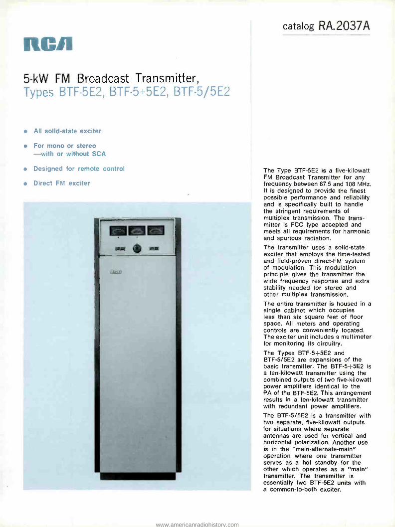
RC/1
5 -kW FM Broadcast Transmitter, Types BTF -5E2, BTF -5 5E2, BTF -5/5E2
All solid -state exciter
For mono or stereo -with or without SCA
Designed for remote control
Direct FM exciter
catalog RA.2037A
The Type BTF -5E2 is a five -kilowatt FM Broadcast Transmitter for any frequency between 87.5 and 108 MHz. It is designed to provide the finest possible performance and reliability and is specifically built to handle the stringent requirements of multiplex transmission. The trans- mitter is FCC type accepted and meets all requirements for harmonic and spurious radiation.
The transmitter uses a solid -state exciter that employs the time -tested and field -proven direct -FM system of modulation. This modulation principle gives the transmitter the wide frequency response and extra stability needed for stereo and other multiplex transmission.
The entire transmitter is housed in a single cabinet which occupies less than six square feet of floor space. All meters and operating controls are conveniently located. The exciter unit includes a multimeter for monitoring its circuitry.
The Types BTF -5 +5E2 and BTF -5/5E2 are expansions of the basic transmitter. The BTF -5 4-5E2 is a ten -kilowatt transmitter using the combined outputs of two five -kilowatt power amplifiers identical to the PA of the BTF -5E2. This arrangement results in a ten -kilowatt transmitter with redundant power amplifiers.
The BTF -5/5E2 is a transmitter with two separate, five -kilowatt outputs for situations where separate antennas are used for vertical and horizontal polarization. Another use is in the "main- alternate- main" operation where one transmitter serves as a hot standby for the other which operates as a "main" transmitter. The transmitter is essentially two BTF -5E2 units with a common -to -both exciter.
www.americanradiohistory.com

RA.2037A
Heart of the BTF -5E2 Transmitter is the solid -state exciter, shown here with stereo and two SCA modules in place.
RCA's Type BTF -5E2 FM Transmit- ter provides 5,000 watts output for sta- tions operations in the 87.5 to 108 MHz band. It is designed to provide the finest possible performance and reliability, and is specifically built to meet the stringent requirements of multiplex and stereo service transmission. It is a simple and compact unit easy to install.
Two Stages Follow Exciter From the 15 -watt output of the BTE-
15A exciter, only two power stages are required to generate the five -kilowatt power level (see block diagram). The power output stage operates in a grounded -grid circuit.
Easy to Install and Operate Other features incorporated in the
BTF -5E2 include silicon rectifiers which provide long life with a minimum of maintenance. Accessibility is assured both front and rear by vertical chassis con- struction, surface mounting of compo- nents, and hinged control panel. Mechani- cal and electrical overload protection is provided. To assure performance in ac- cordance with FCC requirements, the transmitter is supplied with harmonic fil- ter. Provisions for remote control have been provided in the transmitter.
High quality FM stereo transmission can be obtained by the addition of an RCA BTS -1B Stereo Generator. SCA programming may be transmitted simul- taneously with stereo by the use of the optional BTX -1B subcarrier generator. Space for two SCA generators is provided.
Single Cabinet The Type BTF -5E2 FM Transmitter
is completely housed in one cabinet with total floor dimensions of only 26 by 33 inches (660 x 838 mm). The cabinet is
functionally styled to present a pleasing appearance. All meters and operating controls are located conveniently. Front and rear doors give easy access to all portions of the transmitter.
Located at the front are the overload relays and tuning controls for the ampli- fier. A control panel and screen voltage control are located next, followed by the Type BTE -15A exciter system. Concealed in the bottom of the transmitter are the high voltage rectifier and power trans- former. The rear of the transmitter gives access to the RF box, metering circuitry and blower, followed by the rear of the control panel.
www.americanradiohistory.com

BTE -15A Solid -State FM Exciter Excellent monophonic, stereophonic and
SCA subcarrier performance that more than meets industry and FCC standards are achieved by the new RCA modular, solid -state "Direct FM" exciter, operating at carrier frequency.
Simplified Circuits Modulation of the temperature com-
pensated basic on- frequency oscillator is
achieved by applying the composite stereo or SCA signals from the BTS -1B and BTX -1B Generators, respectively, to a pair of push -pull Varicap diodes which are coupled to the basic oscillator fre- quency determining resonant circuit. The output of the basic oscillator is isolated from the following buffer amplifier by a 10 dB resistive attenuator. Thus, the sta- bility and modulation characteristics of the basic, direct -FM oscillator are not disturbed by following power amplifiers.
The output power of the buffer ampli- fier, approximately 500 mW, is used to drive the 15 -watt, three -stage amplifier as well as the binary divider chain in the AFC circuit. The basic oscillator, buffer amplifier, and AFC circuit are mounted inside a shielded enclosure. The power amplifier is also completely shielded.
Automatic frequency control (AFC) for the on- frequency basic oscillator is achieved by taking a sample of the buf- fer output and dividing it by two, 14 times. A low- frequency reference crystal operating at 1 /1024th of the desired out- put frequency is divided by two, 4 times. Integrated circuits operating in the satu- rated mode are used in both binary di- viding chains. The outputs from the ref- erence and basic oscillator binary dividers are phase compared in a time- sharing IC comparator. The output of the circuit, which represents the AFC error voltage, is filtered and applied to another pair of Varicap diodes coupled to the basic oscil- lator tuned circuit. Thus, the basic oscil- lator is phase locked to the 1024th har- monic of the oven controlled reference crystal.
A phase -lock detector is incorporated in the design of the BTE -15A Exciter. When the basic oscillator frequency is not phase locked to the reference crystal, an AC component appears at the AFC output. This voltage is rectified to operate a relay whose contacts can be used to turn off the FM transmitter.
Two multimeters are located on the hinged door of the exciter in front of the regulated power supply section. One of
these meters is used to indicate power supply and operating voltages within the exciter and 15 -watt RF Amplifier. The second meter is a peak- reading voltmeter that is used to indicate all modulating signal levels.
The RF power output of the BTE -15A can be continuously adjusted from the front panel control from 7 to 15 watts. The primary powér is turned on with a circuit breaker. .RF output is turned on with a front panel switch or through an internal relay with connections at the rear of the unit. The exciter tolerates load mismatches from short- circuit to open- circuit for a reasonable time with- out damaging the output transistor. Another feature prevents automatic opera- tion of the 41 -kHz SCA subcarrier when the stereo generator is in the stereo mode.
Grounded -Grid Power Amplifier Two simplified, single -ended amplifiers
follow the exciter. The 250 -watt driver stage uses a Type 8122 tube, and the final power amplifier, operating grounded -grid, uses a triode.
Five -kW Final Amplifier The output tube, a ceramic triode, of-
fers high power -gain. Using this tube, only two stages of amplification are required between the exciter and the antenna for the 5,000 -watt output. Fewer compo- nents results in improved reliability.
RA.2037A
Adjustable Power -Output Control Power output is controlled by means of
a variable resistor which controls the screen -voltage supply of the IPA. The use of semiconductor (silicon) rectifiers in the power supply reduces operating and maintenance costs.
Harmonic Filter The harmonic filter supplied with all
RCA FM transmitters is not a simple harmonic trap. The filter consists of two M- derived half -T sections and three constant -K sections. The M- derived sections at the input and output provide rapid cut -off in the second harmonic re- gion and a termination impedance at each end of the filter of 50 ohms. The use of such a filter assures compliance with FCC requirements regarding spurious radiation, including all harmonics through 1000 MHz.
Self- Protected Against Overload Power circuits are protected by mag-
netically- tripped circuit breakers in addi- tion to overload relays. An automatic se- quencing system prevents turn -on of plate power before all filaments have heated. In addition, a stepping relay automatical- ly cycles power off three times before locking -out in the event of brief over- loads or power interruptions. The over - relays are reset by pushbutton switches on the front panel. A tally light indicates overload in the driver, cathode current,
Simplified Block Diagram of BTF -5E2 Trans- mitter, showing optional stereo and SCA.
LEFT
AUDIO INPUTS
RIGHT
BTS -IB
STEREO
GEN.
EXCITER R.F.
AMPLIFIER 5 WATTS
SCA BTX - I B
SCA GEN
676HZ
REFERENCE CRYSTAL
OSCILLATOR
DRIVER
8122 AUDIO INPUT
SCA OFF
RELAY
FREQUENCY
CONTACTS
TRANSMITTER
CIRCUIT
BTX -a SCA
GEN.
Al RNZ
PA
3C X3000A7 AUDIO
IN PUT TO
CONTROL
EXCITER
POWER
SUPPLY
VARIABLE
LOW VOLTAGE
SUPPLY
NIGH VOLTAGE
SUP PLY
www.americanradiohistory.com

RA.2037A
PA grid current, PA plate current or high -voltage power supply.
Control Features The BTE -15A exciter has a self -con-
tained multimeter. In the amplifier of the transmitter, provision is made for metering PA plate current, plate voltage, output power and VSWR. All tuning con- trols are located on the front panel for easy accessibility. They include switches for filament on -off, plate on -off, and over- load reset. The variable power control is
also mounted on the front as are the overload indicator and plate power -on lights. The use of latching relays make it possible to control the transmitter with one button.
Remote Control Provisions The BTF -5E2 transmitter incorporates
connections for remote control and re- mote meter reading when combined with a remote control system such as the BTR - 15 or BTR -30. Terminals for transmitter on -off, plate on -off, overload reset, plate voltage, cathode current, and power out- put are provided. To control transmitter power output remotely, an accessory motor drive may be connected to the screen voltage control.
Dual- Amplifier Units The BTF -5E2 is available also as a
dual -power -amplifier in two versions: a "BTF -5- plus -5E2" and a "BTF -5- slash-
Specifications Performance Power Output 1000-5000 watts Output Impedance (1%" O.D., unflanged) 50 ohms Frequency Deviation, 100% modulation ±75 kHz Modulation Capability ±100 kHz Carrier Frequency Stability ±1000 Hz max.
Audio Input Impedance 600 /150 ohms Audio Input Level- 1(100% mod.) +10 ±2 dBm Audio Frequency Response-2(50 Hz -15 kHz) ±1 dB max.
Pre -emphasis Network Time Constant 75 or 50 vs Harmonic Distortion -3(50 Hz -15 kHz) 0.5% or less
FM Noise Level (referred to 100% FM mod.) -65 dB max.
AM Noise Level (referred to 100% AM mod.) -50 dB max.
Subcarrier Input Level (100% mod.) -15 to +10 dBm adjustable
Subcarrier Input Impedance 600 /150 ohms bal.
Subcarrier Frequency 20-67 kHz
Main -to- Subchannel Crosstalk -50 dB referred to ± 6.0 kHz deviation of the subcarrier by a 400 Hz tone. Main channel modulation 70% by 50- 15,000 Hz tones.
Sub -to- Main -Channel Crosstalk -60 dB referred to ± 75 kHz deviation of the main carrier by a 400 Hz tone. Subchannel modulated 100% (6.0 kHz /s) by 50 -5000 Hz tones. Subcarrier modulated 30% on main carrier.
Electrical Power Line Requirements:
Line 240/208V, 50/60 Hz*
Combined Voltage Variation and Regulation ±5% Power Consumption (approx.) 9000W
Power Factor (approx.) 90%
*Other line voltages available.
Ordering Information Single -Amplifier, 5-kW FM Transmitter.
Type BTF -5E2 ES- 560916* Dual -Amplifier, 5-kW FM Transmitter,
Type BTF -5 +5E2 ES- 560962* Dual -Output, 5-kW FM Transmitter,
Type BTF -5/5E2 ES- 560923*
Mechanical Dimensions
5E2 ". The BTF -5 +5E2 combines dual identical outputs to result in a trans- mitter with redundant power amplifiers. In the BTF- 5/5E2, the dual amplifiers are equipped with individual harmonic filters and individual outputs. This con- figuration is useful in two ways: to power separate circularly polarized antenna sys- tems for increased on -air dependability or, to power separate vertical and horizon- tal polarization antenna arrays.
The dual- amplifier units use separate power supplies for each power amplifier. This redundancy enhances on -air relia- bility. A redundant exciter is available at extra cost. See BTE-15A exciter catalog pages for ordering information.
(overall) 25" wide, 77" high, 33" deep (635 mm, 1956 mm, 840 mm)
Weight 850 lbs. (385 kg.)
Finish Textured vinyl in charcoal gray and shadow blue, satin aluminum trim
Altitude 7500 ft. max. (2290 m)41
Ambient Temperature Range -20° to +45 °C
Accessories Remote Power Output Control MI- 561023
Recommended Spare RF Transistors for Exciter RO -381
Directional Coupler (for exciter output) MI- 561026
Spare Crystal and Oven (Specify operating frequency) MI- 560717
Spare Transmitter Tubes .... _. _ _ ...__. _ ....ES- 560920
RF Load and Wattmeter MI- 561422
FM Freq. and Mod. Monitor, BW -75 MI- 560735
RF Amplifier, BW -100 MI- 560738
FM Stereo Freq. and Mod. Monitor, BW-85 MI- 560740
SCA Freq. and Mod. Monitor, BW -95 MI- 560745
Remote Control, Type BTR -30 ES- 561446
Remote Control, Type BTR -15 ES- 561157/8
1 Level measured at input to pre -emphasis network.
2 Audio Frequency response referred to 75 or 50 micro-second pre -emphasis Curve.
3 Distortion includes all harmonics up to 30 kHz and is measured following a standard 75 or 50 micro-second de-emphasis network.
Includes one Solid -State Exciter (Type BTE -15A) equipped for main -channel operation only. Stereo and /or SCA subcarrier-generator modules optional. Please specify assigned frequency, power line frequency, operational alti- tude (above sea level) and subcarrier-generator modules desired. Modules ordered with transmitter are factory installed.
www.americanradiohistory.com

RCA Five -Kilowatt FM Transmitters, Types BTF -5E1, BTF -5- plus -5E1, BTF -5/5E1
Entirely solid state exciter
Mono or stereo, with or without SCA subcarriers
Ready for remote control
Expandable to 10- or 20 -kW power level
Available with redundant or dual -parallel power amplifiers
catalog RA.2041A (Replaces B.6505)
The RCA Type BTF -5E1 is a 5 -kW FM Broadcast Transmitter designed for operation in the standard FM broadcast band (87.5 to 108 MHz) and is specifically engineered to the stringent requirements of stereo and multiplex service transmission.
The BTF -5E1 employs the time - tested and field proven "Direct -FM" exciter system. The circuits employ all solid -state components. The inherent long life and cool operation of these devices assure extended reliability in unattended remote operation.
The transmitter features a Type 4CX -5000A power tube driven by a 7203/4CX250B tube in the IPA stage. Silicon- rectifier power supplies also provide long life and dependability. All RF circuits are arranged for utmost tuning simplicity. Except for the high -voltage power supply, the transmitter is housed in a single two -door cabinet. Frequency response of the trans- mitter's main channel is 30 to 15,000 Hz and typical distortion is less than one -half percent. In addition to the five -kilowatt unit, the BTF -5 is available as a BTF -5- plus -5 and a BTF -5/5. The "5- plus -5" is essentially two separate and complete five -kilowatt trans- mitters with combined outputs for ten kilowatts of power. The "5/5" is two separate and complete five - kilowatt transmitters with separate outputs for energizing two separate antenna systems or operation as a main -alternate -main transmitter.
www.americanradiohistory.com
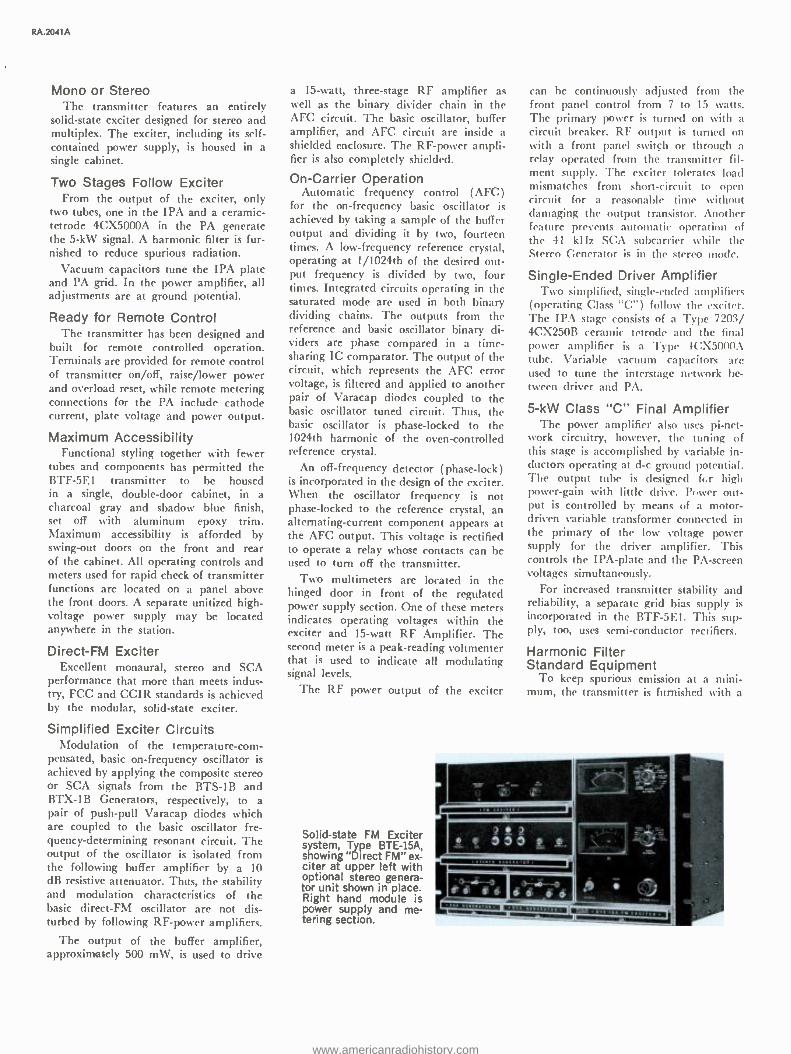
RA.2041 A
Mono or Stereo The transmitter features an entirely
solid -state exciter designed for stereo and multiplex. The exciter, including its self - contained power supply, is housed in a single cabinet.
Two Stages Follow Exciter From the output of the exciter, only
two tubes, one in the IPA and a ceramic - tetrode 4CX5000A in the PA generate the 5 -kW signal. A harmonic filter is fur- nished to reduce spurious radiation.
Vacuum capacitors tune the IPA plate and PA grid. In the power amplifier, all adjustments are at ground potential.
Ready for Remote Control The transmitter has been designed and
built for remote controlled operation. Terminals are provided for remote control of transmitter on /off, raise /lower power and overload reset, while remote metering connections for the PA include cathode current, plate voltage and power output.
Maximum Accessibility Functional styling together with fewer
tubes and components has permitted the BTF -5E1 transmitter to be housed in a single, double -door cabinet, in a charcoal gray and shadow blue finish, set off with aluminum epoxy trim. Maximum accessibility is afforded by swing -out doors on the front and rear of the cabinet. All operating controls and meters used for rapid check of transmitter functions are located on a panel above the front doors. A separate unitized high - voltage power supply may be located anywhere in the station.
Direct -FM Exciter Excellent monaural, stereo and SCA
performance that more than meets indus- try, FCC and CCIR standards is achieved by the modular, solid -state exciter.
Simplified Exciter Circuits Modulation of the temperature-com -
pensated, basic on- frequency oscillator is achieved by applying the composite stereo or SCA signals from the BTS -1B and BTX -1B Generators, respectively, to a pair of push -pull Varacap diodes which are coupled to the basic oscillator fre- quency- determining resonant circuit. The output of the oscillator is isolated from the following buffer amplifier by a 10 dB resistive attenuator. Thus, the stability and modulation characteristics of the basic direct -FM oscillator are not dis- turbed by following RF -power amplifiers.
The output of the buffer amplifier, approximately 500 mW, is used to drive
a 15 -watt, three -stage RF amplifier as well as the binary divider chain in the AFC circuit. The basic oscillator, buffer amplifier, and AFC circuit are inside a shielded enclosure. The RF -power ampli- fier is also completely shielded.
On- Carrier Operation Automatic frequency control (AFC)
for the on- frequency basic oscillator is achieved by taking a sample of the buffer output and dividing it by two, fourteen times. A low- frequency reference crystal, operating at 1 /1024th of the desired out- put frequency is divided by two, four times. Integrated circuits operating in the saturated mode are used in both binary dividing chains. The outputs from the reference and basic oscillator binary di- viders are phase compared in a time- sharing IC comparator. The output of the circuit, which represents the AFC error voltage, is filtered and applied to another pair of Varacap diodes coupled to the basic oscillator tuned circuit. Thus, the basic oscillator is phase -locked to the 1024th harmonic of the oven -controlled reference crystal.
An off -frequency detector (phase -lock) is incorporated in the design of the exciter. When the oscillator frequency is not phase- locked to the reference crystal, an alternating- current component appears at the AFC output. This voltage is rectified to operate a relay whose contacts can be used to turn off the transmitter.
Two multimeters are located in the hinged door in front of the regulated power supply section. One of these meters indicates operating voltages within the exciter and 15 -watt RF Amplifier. The second meter is a peak -reading voltmenter that is used to indicate all modulating signal levels.
The RF power output of the exciter
Solid -state FM Exciter system, Type BTE -15A, showing "Direct FM" ex- citer at upper left with optional stereo genera- tor unit shown in place. Right hand module is power supply and me- tering section.
can be continuously adjusted from the front panel control from 7 to 15 watts. The primary power is turned on with a circuit breaker. RF output is turned on with a front panel switch or through a relay operated from the transmitter fil- ment supply. The exciter tolerates load mismatches from short- circuit to open circuit for a reasonable time without damaging the output transistor. Another feature prevents automatic operation of the 41 kHz SCA subcarrier while the Stereo Generator is in the stereo mode.
Single -Ended Driver Amplifier Two simplified, single -ended amplifiers
(operating Class "C ") follow the exciter. The IPA stage consists of a Type 7203/ 4CX250B ceramic tetrode and the final power amplifier is a Type 4C:X5000A tube. Variable vacuum capacitors are used to tune the interstage network be- tween driver and PA.
5 -kW Class "C" Final Amplifier The power amplifier also uses pi -net-
work circuitry, however, the tuning of this stage is accomplished by variable in- ductors operating at d -c ground potential. The output tube is designed fcr high power -gain with little drive. Power out- put is controlled by means of a motor - driven variable transformer connected in the primary of the low voltage power supply for the driver amplifier. This controls the IPA -plate and the PA- screen voltages simultaneously.
For increased transmitter stability and reliability, a separate grid bias supply is incorporated in the BTF -5E1. This sup- ply, too, uses semi- conductor rectifiers.
Harmonic Filter Standard Equipment
To keep spurious emission at a mini- mum, the transmitter is furnished with a
w Z. I'
er s ie 4
www.americanradiohistory.com

LEFT -Br AUDIO INPUTS
RIGHT -111
BTS -IB STEREO
GEN.
STEREO DIRECT FM
OSCILLATOR ANO
BUFFER
EXCITER R.F.
AMPLIFIER 7-15 WATTS B7 -10B MHz
SCA BTX-1B
SCA GEN.
67 KHz
A FC
REFERENCE CRYSTAL
OSCILLATOR
DRIVER
7203/4CX250B AUDIO
INPUT
SCA
SCA
OFF RELAY
FREQUENCY CONTACTS
TRANSMITTER
CIRCUIT
BTX-1B SCA GEN.
41 KHz
OFF -FRED. DETECTOR
PA
4CX5000A AUDIO -ÿ INPUT
SCA TO
CONTROL
Simplified Block Diagram of the BTF -5E1 Transmitter, showing optional stereo and SCA.
EXCITER
POWER
SUPPLY
VARIABLE LOW VOLTAGE
SUPPLY
HIGH VOLTAGE SUPPLY
PA
BIAS SUPPLY
3%e -inch harmonic filter as standard equipment. The filter consists of a series of transmission line elements with a uni- form outer diameter conductor, a stepped inner conductor, and a shunt stub. The conductors are fabricated of a high -grade copper alloy. Attenuation of all harmonic radiation above channel limits is accom- plished in an "M- derived" section, and a
series of "constant -K" T- sections. This de- sign provides a broad passband with a
sharp high- frequency cut -off and excellent attenuation above the passband.
Self- Protected Against Overload Power circuits arc protected by mag-
netically- tripped circuit breakers in addi- tion to overload relays. An interlocked system prevents turn-on of plate power until all filaments have heated. In addi- tion, a latching relay automatically re- applies power to the transmitter once before locking -out in the event of brief overloads or power interruptions.
Optional Filter Monitor Cooling air is supplied by means of
a blower mounted below the amplifier stages. An optional manometer indicates the efficiency of the fiber -glass filter at the inlet and heavy sound insulation re-
duces blower noise to a minimum. The blower supplies forced air to both stages.
Simplified Control The transmitter has all operating con-
trols and meters located on a panel just above the front doors. The push- button controls include: transmitter on /off, plate on /off, overload reset and power raise/ lower. A low- voltage circuit -breaker, and filament- and control -circuit breakers are located behind the left -hand door. The main -and low -power circuit breakers are located in the rectifier unitized cabinet.
Full Metering Six easy -to -read front -panel meters are
provided for each amplifier. One for PA- plate voltage, another for PA -plate cur- rent, and a third for AC -line and filament voltage. The remaining three are a re- flectometer indicating output, a multi - meter and VSWR meter. Separate meters are used to measure the forward power and VSWR.
Ready for Remote Control Remote control provisions are included
in the transmitter and terminals are provided for use with remote control units such as the Type BTR -15 (or
Ordering Information Single- Amplifier, Five -Kilowatt FM Transmitter,
Type BTF -5E1 ES- 560600 Dual- Amplifier, Ten -Kilowatt FM Transmitter,
Type BTF -5 +5E1 ES- 560637
RA .2041A
BTR -30) and Automatic Logging Equip- ment. Additional terminals are provided for remote control of transmitter on /off, plate on /off, raise /lower power, and overload reset. Remote metering connec- tions in the final amplifier for plate cur- rent, plate voltage, and power output are also provided.
Dual- Amplifier Units The BTF -5L1 is available also as a
ten -kilowatt, dual -power- amplifier trans- mitter in two versions: a "BTF -5 -plus- 5E1" and a "BTF -5- slash -5E1 ". The BTF -5 +5E1 combines dual identical five - kilowatt outputs to result in a ten -kilowatt transmitter with dual -parallel power am- plifiers. In the BTF- 5/5E1, the dual amplifiers are equipped with individual harmonic filters and individual outputs. This arrangement is useful in two ways: to power separate. circularly polarized antenna systems for increased on -air de- pendability or to power separate antennas.
The BTF -5 +5E1 and BTF -5/5E1 units are separate power supplies for each trans- mitter. This redundancy enhances on -air reliability. Both include dual exciter sys-
tems and automatic exciter switchover in the event of exciter system outage.
Dual- Output, Ten -Kilowatt FM Transmitter, Type BTF -5 /5E1 ES- 560603
Please specify assigned frequency, operational altitude and exciter choices (mono, stereo, SCA).
www.americanradiohistory.com

RA.2041 A
Specifications Performance Type of Emission F3 and F9 Frequency Range 87.5 to 108 MHz Power Output 5 kW Output Impedance (31/2" Unflanged Line) 50 ohms Frequency Deviation 100% modulation ±75 kHz Modulation Capability ±100 kHz Carrier Frequency Stability ±1000 Hz max. Audio Input Impedance 600/150 ohms Audio Input Level (100% mod.) +10 ±2 dBm' Audio Frequency Response (50- 15,000 Hz) +1 dB max.' Pre -emphasis Network Time Constant 75 or 50 Ns
Harmonic Distortion (50- 15,000 Hz) 0.5% or less
FM Noise Level (referred to 100% FM mod.) -65 dB max. AM Noise Level (referred to 100% AM mod.) -50 dB max. Subcarrier Input Level (100% mod.) -15 to +10 dBm
adjustable Subcarrier Input Impedance 600/150 ohms bal. Subcarrier Frequency 20-67 kHz Main -to- Subchannel Crosstalk -50 dB referred to +6.0 kHz
deviation of the subcarrier by a 400 Hz tone. Main chan- nel modulation 70% by 50- 15,000 Hz tones.
Sub -to- Main -Channel Crosstalk .-60 dB referred to ±75 kHz deviation of the main carrier by a 400 Hz tone. Subchan- nel modulation 100% ( ±6.0 kHz) by 50 -6000 Hz tones. Subcarrier modulated 30% on main carrier.
Accessories Recommended Spares RF Transistors
(for exciter) RO -381`
Spare Crystal and Oven (Specify carrier freq.) MI- 560717
Spare Tubes, Complete Set ES- 560607
Five -kW RF Load and Wattmeter MI- 561422
Thirty- Function Remote Control, Type BTR -15 ES- 561157/53
Sixty- Function Remote Control, Type BTR -30 ES- 561446
Power Conversion Kit (5- to 10-kW) ES- 560642
RA .2041A
Space- saving floor plan of the BTF -5E1. The separate, unitized power supply may be in- stalled in the basement, attic, closet, or other convenient place. (Wire duct and fan shown are not furnished.)
Electrical Power Line Requirements:
Line 240/208V, 3 phase, 50/60 Hz' Combined Line Voltage Variation and Regulation ±5% Power Consumption (approx.) 10,000 W Power Factor (approx.) 90%
Crystal Heater: Line Power Consumption 71/2 W
Tube Complement Driver: 1- 7203/4CX250B; Power Amplifier: 1- 4CX5000A
Mechanical Dimensions: Transmitter
Width 481/2" (1230 mm) Height 77 "(1956 mm) Depth 321/2" (825 mm) Weight (approx.) 1250 lbs. (567 kg)
Shipping Weight ( approx.) _ _ 2150 lbs. (975 kg) Finish Textured Vinyl in EELM charcoal gray and
shadow blue, aluminum epoxy trim Altitude ..60 Hz Power: 11,00 ft. (3353 m)'
50 Hz Power: 9,000 ft. (2700 m)"
Ambient Temperature Range -20° to +45 °C
117 V, 50/60 Hz
Power Supply 32 "(860 mm) 46" (1381 mm) 24 "(721 mm) 590 lbs. (263 kg)
'Level measured at input terminal. 'Audio Frequency response referred to 50- or 75- microsecond pre- emphasis curve.
'Distortion includes all harmonics up to 30 kHz and is measured following a
standard 50- or 75- microsecond de- emphasis network. 'Blowers available for operation at higher altitudes. Other voltages available optionally.
Specifications subject to change without notice.
Power Conversion Kit (5- to 20-kW) ES- 560643
High Altitude Blower Kit MI- 560347 -3
Mounting Kit (for Blower Kit) MI- 560705
AM Noise Reduction Kit MI- 560307 -31
Indicator, Elapsed Time (60 Hz only) MI- 561018 -2
Indicator, Elapsed Time (50 Hz only) MI- 561018 -4
Manometer MI-560307-36
' Order "RO -" Kits from RCA Parts E. Accessories, Deptford, N. J.
www.americanradiohistory.com

Rcn T en- Kilowatt FM Transmitters,
ypes BTF -10E1, BTF -10- plus -10E1, BTF- 10/10E1
Entirely solid state exciter
Mono or stereo, with or without SCA subcarriers Ready for remote control
Expandable to 20 -kW power level
Available with redundant or dual -parallel power amplifiers
catalog RA.2051A (Replaces B.6510)
The RCA Type BTF -10E1 is a 10 -kW FM Broadcast Transmitter designed for operation in the standard FM broadcast band (87.5 to 108 MHz) and is specifically engineered to the stringent requirements of stereo and multiplex service transmission.
The BTF -10E1 employs the time - tested and field proven Direct -FM exciter system. The circuits employ all solid -state components. The inherent long life and cool operation of these devices assure extended reliability in unattended remote operation.
The transmitter features a Type 4CX10000D power tube driven by 7203/4CX250B tube in the IPA stage. Silicon- rectifier power supplies also provide long life and dependability. All RF circuits are arranged for utmost tuning simplicity. Except for the high -voltage power supply, the transmitter is housed in a single two -door cabinet. Frequency response of the trans- mitter's main channel is 30 to 15,000 Hz and typical distortion is less than one -half percent.
In addition to the ten -kilowatt unit, the BTF -10 is available as a BTF -10- plus -10 and a BTF- 10/10. The "10- plus -10" is essentially two separate and complete ten -kilowatt transmitters with combined outputs for 20 kilowatts of power. The "10/10" is two separate and complete ten - kilowatt transmitters with separate outputs for energizing two separate antenna systems, or, operation as a main -alternate -main transmitter.
www.americanradiohistory.com

RA.2051 A
Mono or Stereo The transmitter features a new exciter
designed for stereo and multiplex. The exciter, including its self -contained power supply, is housed in a single cabinet.
Two Stages Follow Exciter From the output of the exciter, only
two tubes, one in the IPA and a ceramic - tetrode 4CX10000D in the PA generate the full 10 -kW signal. A harmonic filter is furnished to reduce spurious radiation.
Vacuum capacitors tune the IPA plate and PA grid. In the power amplifier, all adjustments are at ground potential.
Ready for Remote Control The transmitter has been designed and
built for remote controlled operation. Terminals are provided for remote control of transmitter on /off, raise /lower power and overload reset, while remote metering connections for the PA include cathode current, plate voltage and power output.
Maximum Accessibility Functional styling together with fewer
tubes and components has permitted the BTF -10E1 transmitter to be housed in a single, double -door cabinet, in a charcoal gray and shadow blue finish, set off with aluminum epoxy trim. Maximum accessibility is afforded by swing -out doors on the front and rear of the cabinet. All operating controls and meters used for rapid check of transmitter functions are located on a panel above the front doors. A separate unitized high - voltage power supply may be located any- where in the station.
Direct -FM Exciter Excellent monaural, stereo and SCA
performance that more than meets indus- try, FCC and CCIR standards is achieved by the modular, solid -state exciter.
Simplified Circuits Modulation of the temperature-com -
pensated, basic on- frequency oscillator is achieved by applying the composite stereo or SCA signals from the BTS -1B and BTX -1B Generators, respectively, to a pair of push -pull Varacap diodes which are coupled to the basic oscillator frequency- determining resonant circuit. The output of the oscillator is isolated from the following buffer amplifier by a 10 dB re- sistive attenuator. Thus, the stability and modulation characteristics of the basic direct -FM oscillator are not disturbed by following RF- power amplifiers.
The output of the buffer amplifier, ap- proximately 500 mW, is used to drive a 15 -watt, three -stage RF amplifier as well
as the binary divider chain in the AFC circuit. The basic oscillator, buffer ampli- fier, and AFC circuit are inside a shielded enclosure. The RF -power amplifier is also completely shielded.
On- Carrier Operation Automatic frequency control (AFC)
for the on- frequency basic oscillator is
achieved by taking a sample of the buffer output and dividing it by two, fourteen times. A low- frequency reference crys- tal, operating at 1 /1024th of the desired output frequency is divided by two, four times. Integrated circuits operating in the saturated mode are used in both binary dividing chains. The outputs from the reference and basic oscillator binary di- viders are phase compared in a time- sharing IC comparator. The output of the circuit, which represents the AFC error voltage, is filtered and applied to another pair of Varacap diodes coupled to the basic oscillator tuned circuit. Thus, the basic oscillator is phase- locked to the 1024th harmonic of the oven -controlled reference crystal.
An off- frequency detector (phase -lock) is incorporated in the design of the exciter. When the oscillator frequency is not phase - locked to the reference crystal, an alter- nating- current component appears at the AFC output. This voltage is rectified to operate a relay whose contacts can be used to turn off the transmitter.
Two multimeters are located on the hinged door in front of the regulated power supply section. One of these meters indicates operating voltages within the exciter and 15 -watt RF Amplifier. The second meter is a peak- reading voltmeter that is used to indicate all modulating signal levels.
The RF power output of the exciter can be continuously adjusted from the front panel control from 7 to 15 watts.
Solid -state FM Exciter system, Type BTE -15A, showing "Direct FM" ex- citer at upper left with optional stereo genera- tor units shown in place. Right hand module is power supply and me- tering section.
The primary power is turned on with a circuit breaker. RF output is turned on with a front panel switch or through a re- lay operated from the transmitter filament supply. The exciter tolerates load mis- matches from short -circuit to open- circuit for a reasonable time without damaging the output transistor. Another feature prevents automatic operation of the 41
kHz SCA subcarrier while the stereo generator is in stereo mode.
Single -Ended Driver Amplifier Two simplified, single -ended amplifiers
(operating Class "C ") follow the exciter. The IPA stage consists of a ceramic 7203/4CX250B tetrode and the final pow- er amplifier is Type 4CXI0000D tube. Variable vacuum capacitors are used to tune the interstage network between driver and PA.
10 -kW Class "C" Final Amplifier The power amplifier also uses pi -net-
work circuitry, however, the tuning of this stage is accomplished by variable inductors operating at d -c ground potential. The output tube is designed for high power - gain with little drive. Power output is controlled by means of a motor -driven variable transformer connected in the pri- mary of the low voltage power supply for the driver amplifier. This controls the IPA -plate and the PA- screen voltages simultaneously.
For increased transmitter stability and reliability, a separate grid bias supply is incorporated in the BTF -10E1. This sup- ply, too, uses semi -conductor rectifiers.
Harmonic Filter Standard Equipment
To keep spurious emission at a mini- mum, the transmitter is furnished with a 3%8 -inch harmonic filter as standard equipment. The filter consists of a series
www.americanradiohistory.com

LEFT
AUDIO INPUTS
RIGHT
SCA AUDIO
INPUT
SCA
AUDIO
INPUT
STEREO
BTS -IB STEREO
GEN.
BTX-113
SCA GEN.
67 KHz
--
BTX -IB SCA GEN.
41 kHz
DIRECT FM
OSCILLATOR AND -M BUFFER
SCA
A FC
EXCITER
R. F.
AMPLIFIER
1
OFF -FREO. DETECTOR
REFERENCE
CRYSTAL
OSCILLATOR
OFF FREQUENCY
RELAY CONTACTS
TO TRANSMITTER
CONTROL CIRCUIT
7-15 WATTS 87 -IOB MHz
DRIVER 7203/4CX250B
PA
4CX10000A
Simplified block diagram of BTF -10E1, showing optional stereo and SCA.
EXCITER POWER
SUPPLY
VARIABLE LOW VOLTAGE
SUPPLY
HIGH VOLTAGE
SUPPLY PA
BIAS SUPPLY
of transmission line elements with a uni- form outer diameter conductor, a stepped inner conductor, and a shunt stub. The conductors are fabricated of a high -grade copper alloy. Attenuation of all harmonic radiation above channel limits is accom- plished in an "M- derived" section, and a series of "constant -K" T- sections. This design provides a broad passhand with a sharp high -frequency cut -off and excellent attenuation above the passhand.
Self- Protected Against Overload l'ower circuits are protected by mag-
netically- tripped circuit breakers in addi- tion to overload relays. An interlocked system prevents turn -on of plate power until all filaments have heated and the exciter has reached a proper operating condition. In addition, a latching relay automatically re- applies power to the transmitter once before locking -out in the event of brief overloads or power inter- ruptions.
Optional Filter Monitor Cooling air is supplied by
a blower mounted below the means of amplifier
stages. An optional manometer indicates the efficiency of the fiber -glass filter at the inlet and heavy sound insulation reduce
blower noise to a minimum. The blower supplies forced air to both stages.
Simplified Control The transmitter has all operating con-
trols and meters located on a panel just above the front doors. The push- button controls include: transmitter on /off, plate on /off, overload reset and power raise/ lower. A low- voltage circuit -breaker, and filament- and control -circuit breakers are located behind the left -hand door. The main- and low -power circuit breakers are located in the rectifier unitized cabinet.
Full Metering Six easy -to -read front -panel meters arc
provided for each amplifier. One for PA- plate voltage, another for PA -plate cur- rent, and a third for AC -line and filament voltage. The remaining three are a reflect - ometer indicating output, a multimeter and VSWR meter. Separate meters are used to measure the forward power and VSWR.
Ready for Remote Control Remote control provisions are included
in the transmitter and terminals are pro- vided for use with remote control units
Ordering Information Single Amplifier, Ten -Kilowatt FM Transmitter,
Type BTF -10E1 Dual- Amplifier, Twenty -Kilowatt FM Transmitter,
Type BTF- 10+10E1
RA.2051 A
such as the Type BTR -I5 (or BTR -30) and Automatic Logging Equipment. Addi- tional terminals are provided for remote control of transmitter on /off, plate on /off, raise /lower power, and overload reset. Remote metering connections in the final amplifier for plate current, plate voltage, and power output are also provided.
Dual- Amplifier Units The BTF -10EI is available also as
a twenty- kilowatt, dual -power -amplifier transmitter in two versions: a "STE-10- plus-10E1" and a "BTF -10- slash- IOE1 ". The BTF- 10 +10E1 combines dual iden- tical ten kilowatt outputs to result in a twenty -kilowatt transmitter with dual - parallel power amplifiers. In the BTF - l0 /10EI, the dual amplifiers are equipped with individual harmonic filters and indi- vidual outputs. This arrangement is useful in two ways: to power separate, circularly polarized antenna systems for increased on -air dependability or, to power separate vertical and horizontal antennas.
The BTF- 10+10E1 and BTF- 10/10E1 units use separate power supplies for each transmitter. This redundancy enhances on- air reliability. Both include dual exciter systems and automatic exciter switchovcr in the event of exciter system outage.
Dual- Output, Twenty -Kilowatt FM Transmitter, ES- 560601 Type BTF- 10!10E1 ES- 560604
Please specify assigned frequency, operational altitude and ES- 560638 exciter choices (mono, stereo, SCA).
www.americanradiohistory.com

RA.2051A
ro.nou
Specifications Performance Type of Emission F3 and F9
Frequency Range 87.5 to 108 MHz Power Output 10 kW Output Impedance (31/e" Unflanged Line) 50 ohms Frequency Deviation 100% modulation ±75 kHz Modulation Capability ±100 kHz Carrier Frequency Stability ±1000 Hz max. Audio Input Impedance 600/150 ohms Audio Input Level (100% mod.) +10 ±2 dBm' Audio Frequency Response (50- 15,000 Hz) ±1 dB max.' Pre -emphasis Network Time Constant 75 or 501.1s
Harmonic Distortion (50- 15,000 Hz) 0.5% or less' FM Noise Level (referred to 100% FM mod.) -65 dB max. AM Noise Level (referred to 100% AM mod.) -50 dB max.
Subcarrier Input Level (100% mod.) -15 to +10 dBm adjustable
Subcarrier Input Impedance 600/150 ohms bal. Subcarrier Frequency 20-67 kHz Main -to-Subchannel Crosstalk -50 dB referred to +5.0 kHz
deviation of the subcarrier by a 400 Hz tone. Main chan- nel modulation 70% by 50- 15,000 Hz tones.
Sub -to -Main Channel Crosstalk -60 dB referred to ±75 kHz deviation of the main carrier by a 400 Hz tone. Subchan- nel modulation 100% ( ±6.0 kHz) by 50 -6000 Hz tones. Subcarrier modulated 30% on main carrier.
Accessories
Recommended Spares RF Transistors (for exciter) RO -381`
Spare Crystal and Oven (Specify carrier freq.) MI- 560717
Spare Tubes, Complete Set ES- 561608 RF Load & Wattmeter, 10 kW Type 8634 Remote Control, Thirty Function, Type BTR -15 ES- 561157/58 Remote Control, Sixty- Function, Type BTR -30 ES- 561446 Power Conversion Kit (10 kW to 20 kW) MI- 560644 High Altitude Blower Kit MI- 560747 -3
Mounting Kit (for Blower Kit) MI- 560705
AM Noise Reduction Kit MI- 560307 -31
Space -saving floor plan of the BTF -10E1. The separate, unitized power supply may be in- stalled in the basement, attic, closet, or other convenient place. (Wire duct and fan shown are not furnished.)
Electrical Power Line Requirements:
Line 240/208V, 3 phase, 50/60 Hz' Combined Line Voltage Variation and Regulation ±5% Power Consumption (approx.) 19,000 W
Power Factor (approx.) 90%
Tube Complement Driver: 1- 7203/4CX250B Power Amplifier: 1- 4CX10000D
Mechanical Dimensions:
Width Height Depth Weight (approx
Finish
Transmitter Power Supply 481/2" (1230 mm) 32" (960 mm) 77 "(1956 mm) 46 "(1381 mm) 321/2" (825 mm) 24" (721 mm)
.) 1300 lbs. (590 kg) 840 lbs. (381 kg) Textured vinyl in EELM charcoal gray and
shadow blue, aluminum epoxy trim Altitude . 60 Hz Power 9,000 ft. (2700 m)'
50 Hz Power 7,500 ft. (2286 m)' Ambient Temperature Range -20° to +45 °C
'Level measured at input terminal. 'Audio Frequency response referred to 50- or 75- microsecond pre -emphasis curve.
'Distortion includes all harmonics up to 30 kHz and is measured following a standard 50- or 75- microsecond de- emphasis network.
'Blowers can be provided for operation at higher altitudes. 'Other voltages available optionally.
Specifications subject to change without notice.
Manometer M I- 560307 -36
Indicator, Elapsed Time (60 Hz only) MI. 561018 -2
Indicator, Elapsed Time (50 Hz only) MI- 561018 -4
Frequency & Modulation Monitor, Type BW -75 .. MI- 560735
Stereo Frequency & Modulation Monitor, Type BW -85 MI- 560740
SCA Frequency & Modulation Monitor, Type BW -95 MI- 560745
RF Amplifier, Type BW -100 (for monitors above) .. MI- 560738
"Order "RO -" kit from RCA Parts 8 Accessories, Deptford, N. J.
www.americanradiohistory.com

RC/1
Twenty -Kilowatt FM Transmitters, Types BTF -20E1, BTF- 20/20E1
Entirely solid state exciter
Mono or stereo, with or without SCA
100 kW ERP with 6- section antenna
Ready for remote control
catalog RA.2061A (Replaces B.6520)
The RCA Type BTF -20E1 is a 20 -kW FM Broadcast Transmitter designed for operation in the standard FM band (87.5 to 108 MHz) and is specifically engineered to the strigent requirements of stereo and multiplex service transmission.
The BTF -20E1 employs the time - tested and field proven Direct -FM exciter system. The circuits employ all solid -state components. The inherent long life and cool operation of these devices assure extended reliability in unattended remote operation.
The transmitter features a Type 4CX15000A power tube driven by two 7203/4CX250B tubes in the IPA stage. Silicon- rectifier power supplies also provide long life and dependability. The RF power circuits are arranged for utmost tuning simplicity. Except for the high -voltage power supply, the transmitter is housed in a single two -door cabinet.
Frequency response of the trans- mitter's main channel is 30 to 15000 Hz and typical distortion is less than one -half percent.
In addition to the twenty- kilowatt unit, the BTF -20 is available as a BTF -40 and a BTF- 20/20. The BTF-40 is essentially two separate and complete twenty -kilowatt transmitters with combined outputs for 40 kilowatts of power. The "20/20" is two separate and complete 20 kilowatt transmitters with separate outputs for energizing two separate antenna systems or for operation as main -alternate -main transmitters.
www.americanradiohistory.com

RA.2061 A
Mono or Stereo The transmitter features an entirely
solid -state exciter designed for stereo and multiplex. The exciter, including its self - contained power supply, is housed in a single cabinet.
Two Stages Follow Exciter From the output of the exciter, only
three tubes, two in the IPA and a ceramic - tetrode 4CX15000A PA generate the full 20 -kW signal. A harmonic filter is fur- nished to reduce spurious radiation.
Vacuum capacitors tune the IPA plate and PA grid. In the power amplifier, all adjustments are at d -c ground potential.
Ready for Remote Control The transmitter has been designed and
built for remote controlled operation. Terminals are provided for remote control of transmitter on /off, raise /lower power and overload reset, while remote metering connections for the PA include cathode current, plate voltage and power output.
Maximum Accessibility Functional styling together with fewer
tubes and components has permitted the new BTF -20E1 transmitter to be housed in a single, double -door cabinet, in a EELM charcoal gray and shadow blue finish, set off with aluminum meter panel and trim. Maximum accessibility is afforded by swing -out doors on the front and rear of the cabinet. All operating controls and meters used for rapid check of transmitter functions are located on a panel above the front doors. A separate unitized high -voltage power supply may be located anywhere in the station.
Direct -FM Exciter Excellent monaural, stereo and SCA
performance that more than meets indus- try and FCC & CCR standards is achieved by the modular, solid -state exciter.
Simplified Circuits Modulation of the temperature-com -
pensated, basic on- frequency oscillator is achieved by applying the composite stereo or SCA signals from the BTS -1B and BTX -1B Generators, respectively, to a pair of push -pull Varacap diodes which are coupled to the basic oscillator frequency- determining resonant circuit. The output of the oscillator is isolated from the following buffer amplifier by a 10 dB re- sistive attenuator. Thus, the stability and modulation characteristics of the basic direct -FM oscillator are not disturbed by following RF -power amplifiers.
The output of the buffer amplifier, ap- proximately 500 mW, is used to drive a 15 -watt, three -stage RF amplifier as well as the binary divider chain in the AFC
circuit. The basic oscillator, buffer ampli- fier, and AFC circuit are inside a shield- ed enclosure. The RF -power amplifier is also completely shielded.
Automatic frequency control (AFC) for the on- frequency basic oscillator is achieved by taking a sample of the buffer output and dividing it by two, fourteen times. A low -frequency reference crys- tal, operating at 1 /1024th of the desired output frequency is divided by two, four times. Integrated circuits operating in the saturated mode are used in both binary dividing chains. The outputs from the reference and basic oscillator binary di- viders are phase compared in a time- sharing IC comparator. The output of the circuit, which represents the AFC error voltage, is filtered and applied to another pair of Varacap diodes coupled to the basic oscillator tuned circuit. Thus, the basic oscillator is phase- locked to the 1024th harmonic of the oven -controlled reference crystal.
An off -frequency phase -lock detector is incorporated in the design of the exciter. When the oscillator frequency is not phase -locked to the reference crystal, an alternating- current component appears at the AFC output. This voltage is rec- tified to operate a relay whose contacts can be used to turn off the transmitter.
Two multimeters are located on the hinged door in front of the regulated power supply section. One of these meters indicates power- supply and operating voltages within the exciter and 15 -watt RF Amplifier. The second meter is a peak- reading voltmeter that is used to indicate all modulating signal levels.
The RF power output of the exciter can be continuously adjusted from the front panel control from 7 to 15 watts. The primary power is turned on with a circuit breaker. RF output is turned on with a front panel switch or through a 208 /240 -volt relay operated from the transmitter filament supply.
The exciter tolerates load mismatches from short- circuit to open- circuit for a reasonable time without damaging the output transistor. Another feature prevents automatic operation of the 41 -kHz SCA subcarrier when the stereo generator is in the stereo mode.
Single -Ended Driver Amplifier Two simplified, single -ended amplifiers
(operating Class "C ") follow the exciter. The IPA stage consists of two ceramic 7203/4CX250B tetrodes operating in par- allel, and the final power amplifier is Type 4CX15000A tube. Variable vacuum capa- citors are used to tune the interstage net- work between driver and PA.
20 -kW Class "C" Final Amplifier The power amplifier also uses pi -net-
work circuitry, however, the tuning of this stage is accomplished by variable inductors operating at d -c ground potential. The output tube is designed for high power - gain with little drive. Power output is
controlled by a motor -driven variable transformer in the primary of the low - voltage power supply. This controls the IPA -plate and the PA- screen voltages simultaneously and thus the power output.
For increased transmitter stability and reliability, a separate grid -bias supply is incorporated. This supply, too, uses semi- conductor rectifiers.
Harmonic Filter Standard Equipment
To keep spurious emission at a mini- mum, the transmitter is furnished with a harmonic filter as standard equipment. The filter consists of a series of trans- mission line elements with a uniform outer diameter conductor, a stepped inner conductor, and a shunt stub. The conductors are fabricated of a high -grade copper alloy. Attenuation of all harmonic radiation above channel limits is accom- plished in an "M- derived" section, and a
Solid -state FM Exciter system, Type BTE -15A, showing "Direct FM" ex- citer at upper left with optional subcarrier gen- erator units shown in place. Right hand mod- ule is power supply and metering section.
MIIIIMEOMMISIIImmEgm
> +_a i-i ti EIREIMmaigni
i ì
www.americanradiohistory.com

RA.206I A
LEFT -. AUDIO INPUTS
RIGHT
SCA AUDIO
INPUT
SCA AUDIO
INPUT
BTS -IB STEREO
GEN.
BTX-18 SCA GEN.
67 kHz
BTX -IB
SCA GEN
411,Hz
STEREO
SC
SC
Simplified Block Diagram of BTF -20E1 FM Transmitter show- ing optional stereo and SCA.
DIRECT FM
OSCILLATOR ANO
BUFFER
AFC
EXCITER
R. F.
AMPLIFIER
OFF -FREQ.
DETECTOR
EXCITER
POWER
SUPPLY
REFERENCE
CRYSTAL OSCILLATOR
OFF FREQUENCY
RELAY CONTACTS
TO TRANSMITTER
CONTROL CIRCUIT
VARIABLE LOW VOLTAGE
SUPPLY
T- IS WATTS BY -IOB MHz
DRIVER 203/4CX250B
DRIVER 203/4C X2509
HIGH VOLTAGE SUPPLY
PA
4CXIS000A
TO HARMONIC FILTER
AND ANTENNA
PA
BIAS SUPPLY
series of "constant -K" T- sections. This de- sign provides a broad passband with a sharp high -frequency cut -off and excellent attenuation above the passband.
Self- Protected Against Overload Power circuits are protected by mag-
netically tripped circuit breakers in addi- tion to overload relays. An interlocked system prevents turn -on of plate power until all filaments have heated. In ad- dition, a latching relay automatically re- applies power to the transmitter once before lock -out in the event of brief overloads or power interruptions. The overload relays are reset by illuminated push- buttons on the front panel. Separate tally -light indicators are provided for over- loads in the driver, power amplifier and low- voltage rectifier circuits.
Optional Filter Monitor Cooling air for the BTF -20E1 is sup-
plied by means of a blower mounted below the amplifier stages An optional mano- meter indicates the efficiency of the fiber -glass filter at the inlet and heavy sound insulation reduces blower noise to a minimum. The blower supplies forced air to both the IPA and PA stages.
Simplified Control The transmitter has all operating con-
trols and meters located on a panel just above the front doors. The push- button controls include: transmitter on /off, plate
on /off, overload reset and power raise/ lower. A low -voltage circuit -breaker, and filament- and control -circuit breakers are located behind the left -hand door. The main- and low -power circuit breakers are located in the rectifier unitized cabi- net. Personnel are protected by fully interlocked rear doors, in addition to interlocked doors on the RF PA cubicle.
Full Metering Six easy -to -read front -panel meters are
provided for each amplifier. One for PA- plate voltage, another for PA -plate cur- rent, and a third for AC -line and filament voltage. The remaining three are a reflect - ometer indicating output, a multimeter and VSWR meter. Separate meters are used to measure the forward power and VSWR. The multimeter reads the grid current, the screen current and the screen voltage of both power tubes. In addition, the exciter has its own self- contained multimeter. This one provides complete information on operating conditions in the exciter.
Ready for Remote Control Remote control provisions are included
in the transmitter and terminals are provided for use with remote control units such as the Type BTR -15 (or BTR -30) and Automatic Logging Equip- ment. Additional terminals are provided for remote control (momentary contact) of transmitter on /off, plate on /off, raise/
Ordering Information Single Amplifier, 20-kW Transmitter,
Type BTF -20E1 ES- 560602 Dual- Amplifier, 40-kW Transmitter,
Type BTF -40E1 ES- 560606
lower power, and overload reset. Re- mote metering connections in the final amplifier for plate current, plate voltage, and power output are also provided.
High -Voltage Power Supply The high -voltage power supply is
housed in a unitized cabinet measuring 32" wide, 24" deep and 46" high (813 x 610 x 1168 mm). It can be installed at any convenient place in the station.
Parallel /Redundant Systems The BTF -20E1 is available also as a
dual- power- amplifier transmitter in two versions: a Type BTF -40E1 and a BTF - 20/20E1. The BTF -40E1 combines dual identical twenty -kilowatt outputs to re- sult in a forty -kilowatt transmitter with parallel amplifiers (see catalog pages on Type BTF- 40E1). In the BTF- 20/20E1, the dual power amplifiers are equipped with individual harmonic filters and individual outputs. This arrangement is useful in two ways: to power separate, circularly polarized antenna systems for increased on -air dependability or, to power separate vertical and horizontal polarization antenna arrays independently.
The BTF -40E1 and BTF- 20/20E1 units use a separate power supplies for each transmitter unit. This redundancy en- hances on -air reliability. Both transmitter systems include dual exciter systems and automatic exciter switchover in the event of exciter outage.
Dual- Output, 40-kW Transmitter, Type BTF- 20/20E1 ES- 560605
Please specify assigned frequency, operational altitude and exciter choices (mono, stereo, SCA).
www.americanradiohistory.com

RA.2061A
roiooaooarooia000aioaiiii _> ioaioiiaiiaiiaaiiiiiaiaiaiooioiioi
i
M. Oval
raw ',moo
(Soldwq Ake
rietagen
VO
i
Specifications
Performance Type of Emission_.. _...._......_...._._..._.____._ _ ___......_...._...F3 and F9
Frequency Range 87.5 to 108 MHz Power Output 20 kW
Output Impedance (31/2" O.D. unflanged) 50 ohms Frequency Deviation 100% modulation ±75 kHz Modulation Capability ±100 kHz Carrier Frequency Stability ±1000 Hz max. Audio Input Impedance Resistive, 6001150 ohms Audio Input Level (100 %) mod.) +10 ±2 dBm' Audio Frequency Response (50- 15,000 Hz) ±1 dB max.' Pre -emphasis Network Time Constant....75 or 50 µs, as desired Harmonic Distortion (50- 15,000 Hz) 0.5% or less' FM Noise Level (referred to 100% FM mod.) -65 dB max. AM Noise Level (referred to 100% AM mod.) -50 dB max. Subcarrier Input Level (100% mod.) -15 to +10 dBm
adjustable Subcarrier Input Impedance 600 /150 ohms bal. Subcarrier Frequency 20-67 kHz
Accessories Recommended Spares, RF Transistors
(for exciter) RO -38V Spare Crystal and Oven
(Specify Carrier Frequency) Ml- 560717
Spare Tubes, Complete Set ES- 561609
RF Load and Wattmeter, 20 kW MI -19267
Manometer MI-560307-36 Remote Control System Type BTR -15 ES- 561157/58 Remote Control System Type BTR -30 ES- 561446
High Altitude Blower Kit MI- 560347 -3
Space- saving floor plan of the BTF -20E1. Some units use three -inch diameter harmonic filter (inset). The separate, unitized power supply may be installed in a basement, attic, closet or other convenient place. (Wire duct and fan shown in drawing not furnished.)
Main -to- Subchannel Crosstalk -50 dB referred to ±6.0 kHz deviation of the subcarrier by a 400 Hz tone. Main chan- nel modulation 70% by 50- 15,000 Hz tones.
Sub -to- Main -Channel Crosstalk -60 dB referred to ±75 kHz deviation of the main carrier by a 400 Hz tone. Subchan- nel modulation 100% (±6.0 kHz) by 50 -6000 Hz tones. Subcarrier modulated 30% on main carrier.
Electrical Power Line Requirements:
Line 240/208 volt, 3 phase, 50/60 Hz'
Combined Line Voltage Variation and Regulation ±5% Power Consumption (approx.) 36,000 watts Power Factor (approx.) 90%
Tube Complement Driver: Two Type 7203/4CX250B; PA: One 4CX15000A
Mechanical Dimensions (overall): Transmitter Power Supply
Width 481/2" (1230 mm) 32" (813 mm)
Height 77" (1956 mm) 46" (1168 mm)
Depth 321/2" (825 mm) 24" (610 mm)
Weight (approx.) 1425 lbs. (646 kg.) 1025 lbs. (465 kg.)
Shipping W. (approx) 1600 lbs. (726 kg.) 1100 lbs. (499 kg.)
Finish Textured vinyl in EELM charcoal gray and shadow blue, aluminum en- amel panels.
Altitude 50 Hz Power 3000 ft. (915 m) 60 Hz Power 7500 ft. (2290 m)'
Ambient Temperature Range......_..._..._.__..._ _.... -20° to +45 °C
'Level measured at input terminal. 'Audio Frequency response referred to 50- or 75 -us pre- emphasis curve. 'Distortion includes all harmonics up to 30 kHz and is measured following a
standard 50- or 75 -µs de -emphasis network. 'Other line voltages available optionally. 'Using optional Blower Kit 50 Hz: 6500' (1983 m); 60 Hz: 11,000' (3355 m).
Specifications subject to change without notice.
Blower Mounting Kit MI- 560705
AM Noise Reduction Kit MI- 560307 -31
Indicator, Elapsed Time: 60 Hz power only MI- 561018 -2
50 Hz power only MI- 561018 -4
Freq. & Mod. Monitor BW -75 MI- 560735
Stereo Freq. & Mod. Monitor BW -85 MI- 560740
SCA Freq. & Mod. Monitor BW -95 MI- 560745
RF Amplifier BW -100 MI- 560738
"Order from RCA Parts & Accessories, Deptford, N.J.
www.americanradiohistory.com

RCA Forty- Kilowatt FM Transmitter, Type BTF -40E1
Dual- redundant exciters, amplifiers, power supplies
Ready for remote control
Built for continuous operation
Direct -FM for full -fidelity mono or stereo with or without SCA
Only six tubes in entire transmitter -of only two types
catalog RA.2071A (Replaces B.6535)
The Type BTF -40E1 is a forty -kilowatt transmitter for the maximum -power FM- broadcast station where con- tinuous operation is important. The transmitter combines two identical twenty -kilowatt transmitters to form a redundant forty -kilowatt system. The dual design even allows major maintenance without interruption of air -time.
The BTF -40E1 is a single- output transmitter. Those seeking a dual - output transmitter should consider the Type BTF- 20/20E1 transmitter. This system uses two 20 -kW systems designed for sectionalized antenna systems.
MEN o o O cUo__
®®®®® CJ Li ip cuc
www.americanradiohistory.com

RA.2071A
The BTF -40E1 is a forty- kilowatt, redun- dant transmitter for the maximum -power FM- broadcast station operating on a con- tinuous schedule.
The transmitter is actually two complete twenty- kilowatt units, (Type BTF -20E1) combined to make continuous operation practical. All major components - except the combining equipment and the har- monic filter - are duplicated within the system: twin exciters, twin intermediate power amplifiers, twin finals, twin power supplies, etc. (see block diagrams, oppo- site).
The BTF -40E1 is intended for operation into a single transmission line and antenna system. Systems with redundant antenna systems or main alternate -main transmit- ters should use the Type BTF- 20/20E1 transmitter. This unit is essentially a BTF - 40E1 with dual, identical 20 -kW outputs.
Dual, Switchable Exciters The BTF -40E1 includes two solid -state
exciter systems arranged so that one of the two serves the transmitter while the other operates as a hot standby. In the event of trouble in the on -air exciter, manual switchover puts the extra exciter
on the line. Lighted indicators on the control panel show the change in status.
The exciter systems are identical in all respects and the plug -in modules are in- terchangeable between systems. Each ex- citer unit uses four modules in a main frame. The main frame houses the exciter system power supply and two multimeters: one for d -c parameters and one for audio parameters.
The upper left module houses the RF portions of the system: the oscillator, AFC and amplifiers. The module at center left is a stereo generator module when the exciter is equipped for stereo program- ming.
In a mono -only exciter, this is an audio - input module which interfaces the program line with the frequency -modulated oscilla- tor.
The spaces at the lower edge of the unit accommodate one or two SCA subcarrier generator modules. More information on the exciter system is available in a separate catalog section.
Power -Amplifier Stages The exciter system delivers 15 watts of
modulated carrier to a hybrid -ring power splitter which, in turn, provides two out-
puts. A pair of paralleled tetrodes, in each transmitter section, raise the power level to drive the final power amplifier in each section. The final stage raises the power level to 20 kW. The two 20 -kW outputs are combined into a 40 -kW in a hybrid combiner.
Hybrid Combiner Network Ordinarily mounted above the trans-
mitter cabinet, almost directly over the center unit, (see floor plan, next page) is the combiner network, a "three -dB hybrid" coaxial unit. This assembly com- bines the two 20 -kW modulated carriers into one 40 -kW output. The reject loads for the combiner are mounted within the center cabinet of the transmitter.
Coaxial Harmonic Filter 'File harmonic filter is a series of trans-
mission -line elements with a uniform 6 %- inch outer- conductor diameter, a stepped inner conductor and a shunt stub. Atten- uation of all harmonics is accomplished in an M- derived section and a series of constant -K, T sections. The filter has a broad passband with a sharp high- frequen- cy cutoff and excellent attenuation above cutoff frequency.
Forty -Kilowatt FM Transmitter, Type BTF -40E1
111111.11111.111 NNWo O o1..Yt Pik
MUM W 1111'
.111111..
i -
i
www.americanradiohistory.com

Central Transmitter Control In the center cabinet arc the control
and metering functions for the combined transmitters. Push -buttons provide control of combined unit on /off and plate power on /off. Lighted indicators signal d -c over- load and output line VSWR overload. Three meters, at the top edge, display reject power, reflected power and com- bined power output.
In the area immediately below the meter panel are reflectometer controls and ad- justments. Next are the lighted control switches for the exciter systems, a control - ladder circuit- breaker and a meter that displays reject power. Next is the control knob for adjustment of the "line- stretcher," which adjusts the phase of the input cir- cuits of the twin power- amplifier chains.
Relays in this section switch exciter system inputs, outputs and primary power. This means that the audio conections In the stereo and SCA subchannels arc switched automatically when the exciters are switched.
Built for Continuous Operation The BTF -40E1 Transmitter, by virtue
of its two independent transmitter systems, is arranged so that either twenty- kilowatt system can be shut down for major (or minor) maintenance while the other feeds the antenna.
As a result, the station using a BTF - 40E1 need only reduce power (instead of shutdown) while performing transmitter maintenance. The only transmitter ele- ments common to both subsystems are the hybrid -ring power splitter, (between the exciter and the IPA stages) the output combiner network and the harmonic filter. All three of these are passive devices and require only minimal maintenance.
Redundant Power Supplies The redundancy of the BTF -40E1 sys-
tem extends even to separate power sup- plies for each twenty -kilowatt section. These are units using solid -state rectifiers throughout for reduced maintenance and minimal operating expense. The power supply cabinets need not be located in the same room as the transmitter unit where space is a problem. They might, for example, be located in a basement room or in a shelter external to the trans- mitter building. More information on the twenty -kilowatt transmitter will be found in the catalog section on the Type BTF - 20E1.
RA.2071A
Block diagram of the BTF -40E1 FM Transmitter.
STE- NSA
EXCITER
STE -ISA EXCITER 0-1
err -20E1 POWER
SUPPLY
BRIO RINGI POWER
SPLITTER
AUDIO INPUT
ó INPUT
S n -ID S CA DEN,
S ICK,
S TS-1111
S CA
K N.
1 XKT
REJECT LOAD
BTF-20E1
STF-20E1
3DB HYBRID COUPLER
STE -20E1 POWER SUPPLY
ANTENN
I
HARMONIC FILTER
REJECT LOAD
-ID WATTS ST-NM MOT
N EXCITER EF
AMPLIFIER
D RUT OSCILLATOR
D
WPM - 1171 AFC
REFERENCE DRIVER CRYSTAL
OSCILLATOR 0340(23
040AR Orr -FCW.
OFF FREQUENCY
ConA'" DF4ivR oGKSINER
DCA OCTCCTOS TO ITER 3o5/C 2R 500
40KW BTF-40E1 SUPP
POWER
CONTROL CIRCUIT
VARiABLE LOW VOLTAGE
SU RP, NIGN VOLTAGE
SUPPLY PA
NIAS SUPPLY
Block diagram of one of the diplesed 20 -kW units of the BTF -40E1 Transmitter, showing optional Stereo and SCA.
® , J®
L
L.
Exciter unit. "Stereo Generator" and two "SCA Generators" are optional. Note dual meters, one for dc parameters, one for audio measurements.
www.americanradiohistory.com

RA.2071A
Space -saving floor plan. The separate, unitized power supplies may be installed in a basement, another room or other convenient place. Wire ducts shown are not furnished.
Specifications Performance Type of Emission F3 and F9 Frequency Range 87.5 to 108 MHz Power Output 40 kW Output Impedance (61/8" O.D. Unflanged Line) 50 Ohms Frequency Deviation 100% modulation +75 kHz Modulation Capability ±100 kHz Carrier Frequency Stability ±1000 Hz max. Audio Input Impedance 600 /150 Ohms Audio Input Level -*(100% mod.) +10 ±2 dBm Audio Frequency Response- * *(50- 15,000 Hz) ±1 dB max. Pre -emphasis Network Time Constant....75 or 50 ps, as desired Harmonic Distortion- * * *(50- 15,000 Hz) 0.5% or less FM Noise Level (referred to 100% FM mod.) -65 dB max. AM Noise Level (referred to 100% AM mod.) -50 dB max. Subcarrier Input Level (100% mod.) -15 to +10 dBm
adjustable Subcarrier Input Impedance 600/150 Ohms bal. Subcarrier Frequency 20-67 kHz Main -to- Subchannel Crosstalk.... -50 dB referred to ±7.5 kHz
deviation of the subcarrier by a 400 Hz tone. Main chan- nel modulation 70% by 50- 15,000 Hz tones.
Sub -to- Main -Channel Crosstalk.... -60 dB referred to ±75 kHz deviation of the main carrier by a 400 Hz tone. Subchan- nel modulation 100% ( ±7.5 kHz) by 50 -6000 Hz tones. Subcarrier modulated 30% on main carrier.
Tube Complement Driver: four 7203/4CX250B; Power Amplifier: two 4CX15000A
Electrical Power Line Requirements:
Line 240/208 Volt, 3 phase, 50/60 Hz Combined Line Voltage Variation and Regulation ±5% Power Consumption 72,000 Watts (approx.) Power Factor (approx.) 90%
Mechanical High -Voltage Dimensions (overall): Transmitter Power Supply
Width 1141 /4" (2882 mm) 64" (1626 mm) Height 77 "(1956 mm) 49 "(1245 mm) Depth 321/2" (825 mm) 23 (585 mm)
Weight (approx.) 2950 lbs. (1336.4 kg) 2050 lbs. (329.8 kg.) Finish Textured Vinyl in midnight blue and
shadow blue, satin- aluminum trim. Altitude 7500 ft. (2290 m)t Ambient Temperature Range -20e to +45 °C
Level measured at input to pre-emphasis network. Audio Frequency response referred to 50- or 75- microsecond pre-emphasis curve. Distortion includes all harmonics up to 30 kHz and is measured following a standard 50- or 75- microsecond de- emphasis network. Blowers available for operation at higher altitudes.
Specifications subject to change without notice.
Forty -Kilowatt FM Broadcast Transmitter, Type BTF -40E1 . ES- 560606
Please specify assigned frequency, power line frequency (if other than 60 Hz), and installation altitude if greater than 7500 feet (2300m) above sea level. Stereo and/or SCA facili- ties ordered with transmitter are factory installed.
tir
EXHAUST FAN 6600 CFM (192m)) (Nor SUPPLIED)
2r 16"
TO INCOMING POWER SOURCE
2
POWER SUPPLY
TO INCOMING POWER SOURCE
o HARMONIC FILTER 6'( O D
M1- 561575
TO ANTENNA
I`122 D11 .Dr(Se TO 10BMH,)
TE
.II'i ,I1 . - o tlì WrIZZI'EM NO
HARMONIC FILTER MAY SE ROTATED ABOUT TRAMSMI OUTPUT LINE AS REQUIRE
20 NW TRANSMITTER UNIT
PARENTHETICAL DIMENSIONS ARE IN MILLIMETERS
es and Options Manometer M I- 560307 -36 Elapsed -Time Indicator M I-561018-2) AM Noise Reduction Kit MI- 560307 -31 Freq. & Mod. Monitor, Type BW -75 MI- 560735 Stereo Freq. & Mod. Monitor, Type BW -85 MI- 560740 SCA Freq. & Mod. Monitor, Type BW -95 _ MI- 560745 RF Amplifier, Type BW -100 (for off-air mon.) . MI- 560738 Semiconductor Spares Kit (for Exciter) .. .MI- 560718 Crystal and Oven Spares Kit (for Exciter) MI- 560717
(Please specify carrier frequency) Electron Tube Spares, Complete Set ES- 560613 Remote Control System, Type BTR -15 ES- 561157 Remote Control System, Type BTR -30 . ES- 561446 Exciter System Modules, Spare:
Exciter Modu!e MI- 560712 Stereo Module MI- 560713 SCA Module (Specify subcarrier freq.) _ _._ _MI- 560714
Directional Couplers (Mounted on 11" sections of unflanged 50 -ohm line):
Forty Kilowatt (61/2" line) MI- 560708A Forty Kilowatt (31/2" line) MI- 560708E Twenty Kilowatt (31/2" line) MI- 5607088 Ten Kilowatt (31/2" line) MI- 560703C Five Kilowatt (31 /e" line) MI- 560708D
For 117V/60 Hz power only; use MI- 551018 -4 for 117V /50 Hz.
www.americanradiohistory.com

ncn FM Transmitter Monitors and Accessories
catalog RA.2111A (Replaces B.6820)
These four units, in combination, form a complete FM- transmitter monitoring facility. The unit packaging permits eight combinations that suit the monitoring
Expandable monitor system task at hand without unnecessary invest- ment. Too, unit packaging allows systems
Fully solid -state electronics expansion as additional services are added to the transmitter. For example, a new
Main -channel, stereo and SCA monitoring station operating monophonic needs only a main -channel monitor; adding an SCA sub -channel requires an SCA monitor; Built -in calibration facilities adding stereo programming adds a stereo monitor to the system. Note that the ad- ditional needs do not obsolete existing monitor(s).
FM Monitor - Type BW -75A The Type BW -75A monitors main car-
rier frequency and combined main -carrier modulation: main channel, stereo and all SCA- subcarriers, if used. It samples the transmitter output or uses an off -air signal amplified by the Type BW -100B described below.
Extendable meter circuitry
FM Monitor -Type BW -75A
s
SCA Monitor -Type BW -95A
Stereo Monitor -Type BW-85A
FM RF Amplifier -Type BW -100B
Stereo Monitor - Type BW -85A The Type BW -85A monitors pilot fre-
quency and amplitude plus the other signal components associated with stereo transmission. It is designed to work with a Type BW -75A FM Monitor. The BW- 75A supplies a demodulated maincarrier signal and power for the BW -85A.
SCA Monitor - Type BW -95A The Type BW -95A SCA Monitor
monitors up to four SCA subcarrier frequencies, subcarrier amplitude and modulation. Like the stereo monitor, it requires a Type BW -75A Monitor as a main -carrier demodulator.
FM RF Amplifier - Type BW -100B The BW -100B is available for those who
prefer or need to monitor from an off -air signal. It amplifies the signal to a level suitable for the input requirements of the Type BW -75A Monitor.
Each of these units is described in greater detail on the pages which follow.
www.americanradiohistory.com
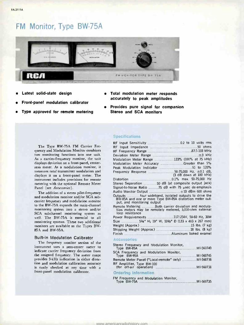
RA.4111A
FM Monitor, Type BW -75A
WM MI RCA FM MONITOR TYPE BW 75A
Latest solid -state design
Front -panel modulation calibrator
Type approved for remote metering
Total modulation meter responds accurately to peak amplitudes
Provides pure signal for companion Stereo and SCA monitors
The Type BW -75A FM Carrier Fre- quency and Modulation Monitor combines two monitoring functions into one unit. As a carrier -frequency monitor, the unit displays deviation on a front -panel, center - zero meter. As a modulation monitor, it measures total transmitter modulation and displays it on a front -panel meter. The instrument includes provisions for remote metering with the optional Remote Meter Panel (see Accessories).
The addition of a stereo pilot- frequency and modulation monitor and /or SCA sub - carrier frequency and modulation monitor to the BW -75A expands the main -channel monitoring system into a stereo and /or SCA subchannel monitoring system as well. The BW -75A is essential to all monitoring systems. These two additional monitors are available as the Types BW- 85A and BW -95A.
Built -In Modulation Calibrator The frequency monitor section of the
instrument uses a zero -center meter to indicate carrier frequency deviation from the assigned frequency. The meter range provides 3 -kHz indication in either direc- tion and modulation calibration accuracy is easily checked at any time with a front -panel modulation calibrator.
RF Input Sensitivity 0.2 to 10 volts rms RF Input Impedance 50 ohms RF Frequency Range 87.5 -103 MHz Deviation Meter Range ±3 kHz Modulation Meter Range 133% (100% at 75 kHz) Modulation Meter Accuracy Greater than 5%
Peak Modulation Indicator 50 to 120%
Frequency Response 50- 75,000 Hz, ±0.1 dB, (3 dB down at 180 kHz)
Distortion 0.1% max. 50- 75,000 Hz
Stereo Separation 50 dB (at composite output jack) Signal -to -Noise Ratio 75 dB with 75 µsec de- emphasis Audio Monitor Output +10 dBm 600 ohms Outputs . _ _. four wideband, isolated outputs to drive the
BW -85A and one or more Type BW -95A distortion meter out- put, and monitoring output
Remote Metering Both carrier deviation and modula- tion meters may be remotely metered, 5,000 -ohm external loop resistance
Power Requirements 117/234V, 50-60 Hz, 30W
Size 5114" H; 19" W; 101/2" D (133 x 483 x 267 mm) Weight (Approx ) 15 lbs. (7 kg)
Shipping Weight (Approx.) 18 lbs. (8 kg)
Finish Aluminum baked enamel
Stereo Frequency and Modulation Monitor, Type BW-85A M I- 560740
SCA Frequency and Modulation Monitor, Type BW -95A MI- 560745
Remote Meter Panel ( "Local- remote" only) MI- 560736
RF Amplifier, Type BW -100 (for off -air operation) MI- 560738
Ordering Information FM Frequency and Modulation Monitor,
Type BW -75A MI- 560735
www.americanradiohistory.com

Stereo Monitor, Type BW -85A
RCA STEREO MONITOR TYPE BW 85A
Unique phase discriminator allows critical phase adjustments
The Type BW -85A Stereo Frequency and Modulation Monitor is a companion unit to the BW -75A FM Monitor. It in- cludes monitoring facilities for stereo programming: The BW -75A monitors main-carrier frequency and modulation while the BW -85A monitors stereo pilot frequency and stereo modulation. The BW -85A is type approved for use only with the BW -75A unit. (FCC Approval No. 3 -146.)
The BW -85A monitors all required para- meters of the stereo composite signal after demodulation of the main carrier by the Type BW -75A. In addition, the unit pro- vides test facilities that aid in periodic maintenance checks.
The unit measures FM noise, AM noise, incidental AM, separation, cross talk, pilot frequency amplitude and subcarrier sup- pression. A unique filter system allows monitor use as an intermodulation ana- lyzer which measures stereo distortion directly in the frequency range between five and fifteen kilohertz.
A special feature of the BW -85A is a pilot -phase regeneration system that uti- lizes a phase discriminator. This arrange- ment results in a null at the correct phase angle which, in turn, allows phase angle regeneration to within one -quarter degree.
A remote metering panel (see Acces- sories) allows meter displays at remote locations away from the monitor.
Complete stereo monitoring and test functions
Convenient front panel metering
Pilot Frequency Meter Range ±3 Hz Pilot Frequency Meter Accuracy ±0.2 Hz (0.001 %) Modulation Meter Range 133% to -70 dB Modulation Meter Accuracy Better than 5% Frequency Response (L and R) ±0.5 dB (50- 15,000 Hz) Separation 45 dB (50- 15,000 Hz); Meter Range -70 dB Crosstalk 60 db L+R to L -R, 60 dB L -R to L +R,
66 dB SCA to L +R, L -R Outputs:
Left & Right Channel Monitoring +4 dBm, 600 ohms, unbal.
Left & Right Channel Test 10 kohms, unbal. Distortion (Either Channel) 0.2%
Signal -to -Noise Ratio (Either Channel) 70 dB with 75 Nsec. de- emphasis
Monitoring Modes (Modulation Meter Switched 133% to -70 dB) Left Channel Audio,
Right Channel Audio, L +R, L -R, 38 kHz (May be meas- ured with modulating frequencies greater than 5 kHz), 19 kHz Pilot Injection (12% full scale), Total Modulation, FM Noise, AM Noise, Incidental AM
Remote Metering Both pilot frequency and modulation meters may be remotely metered, 5000 ohms external loop resistance
Power Requirements Connects to BW -75A Size 5t/a" H, 19" W, 101" D (133 x 483 x 267 mm) Weight (Approx.) 13 lbs. (6 kg) Shipping Weight 16 lbs. (7'kg) Finish Aluminum baked enamel
Arrr'ccr,rin_
Remote Meter Panel ( "Local- remote" only) Ml- 560741
Ordering Information
Stereo Frequency and Modulation Monitor, Type BW -85A Ml- 560740
RA.2111A
www.americanradiohistory.com

RA.21 11 A
SCA Monitor, Type BW -95A
NM MI RC/1
Complete SCA monitoring to four channels
Three deviation ranges (6, 4 and 2 kHz)
Remote metering facilities
Minimum distortion and crosstalk
Separate peak flasher for SCA modulation
Built -in modulation calibrator
I'he Type BW -95A SCA Frequency and Modulation Moni- tor, used in conjunction with the BW -75A FM Frequency and Modulation Monitor, allows complete monitoring and test functions for subcarrier programming or remote telemetry applications. Four crystal -switch positions enable up to four channels to be operated and tested.
Partially integrated, the solid -state electronics of the BW- 95A allow unlimited SCA frequency selection through a series of interchangeable crystals. With the appropriate crystals, is is possible to monitor four subcarrier channels through pushbutton selection. A frequency change is simply a matter of crystal change.
The BW -95A is a companion equipment to the RCA BW -75A and BW -85A monitor. It incorporates all the latest electronic -design techniques. Lightweight and occupying but 5' inches of rack space, it derives its signal, a virtually pure, distortionless demodulated signal, from the BW -75A Monitor.
Features of the BW -95A include three deviation ranges: Six, four and two kHz for optimum operation.
Specifications Frequency Range Any four SCA frequencies
(switchable) up to 74 kHz Deviation Meter Range ±2 kHz Modulation Meter Range 133% (100% at ±6 kHz,
±4 kHz, or ±2 kHz, switched) Modulation Meter Accuracy Within 5% over
entire scale Maximum Modulation Frequency 5 kHz at 6 kHz deviation SCA Modulation Calibrator 2 kHz SCA Subcarrier 24 kHz to 74 kHz, four switched
crystal positions. SCA subcarrier and deviation main- tained in the FCC allowable total frequency deviation
SCA Injection Level 133% to 5% Peak Indicator Follows deviation scale 50 to 120% Frequency Response ±1 dB, 50 -5,000 Hz Crosstalk Rejection 65 dB or greater Crosstalk Meter Range 70 dB (10 dB steps) Outputs Distortion meter, aural monitor, oscilloscope Audio Monitoring Output 0 dBm 600 ohms Remote Metering Facility Both meters, separate
circuits, 5000 ohms external loop resistance Power Requirements 117/234V, 50-60 Hz, 15W
Size 51/4" H, 19" W, 101/2" D (133, 483, 267 mm) Weight (Approx.) 14 lbs. (6 kg) Shipping Weight (Approx.) 18 lbs. (8 kg) Finish Aluminum baked enamel
Special Note The Type BW -95A monitors all required parameters of the SCA portion of a composite waveform which the RCA BW -75A demodulates from the carrier. As a result, the BW -95A SCA Monitor is FCC type- accepted only when used with the RCA Type BW -75A FM Monitor.
Accessories Remote Metering Panel ( "Local- remote" only) MI- 560746
Ordering Information SCA Monitor, Type BW -95A
(Specify SCA subcarrier frequencies) MI- 560745
RF Amplifier, Type BW -100B A selective, radio- frequency amplifier for use with a BW -75A Monitor (and its loads) as an off -air monitor. The BW -100B ti is entirely solid -state with outstanding selectivity, wide dynamic range, linear phase- bandwidth, symmetrical (zero -axis) limit- ing and 100- microvolt sensitivity.
Respone at ±400 kHz -25 dB Power Requirements 117 V ±10 %, 50/60 Hz, 5 W.
Dimensions 31/2" H, 19" W, 101/2" D (89, 483, 267 mm) Specifications Input Frequency Range 87.5 to 108 MHz Weight 71/2 lbs. (3 kg)
Minimum Input Level (for threshold of limiting) 100 my Shipping Weight (Approx.) 12 lbs. (5 kg)
Maximum Input Level 0.5 V Finish Aluminum baked enamel
Input Impedance 50 to 75 ohms Output Impedance 50 ohms Recommended Antennas Output Level Adjustable to 1 watt Taco Model Y51 -FM
Bandwidth (3 dB points) ±225 kHz Scala Model CA5 -150
Phase Linear Bandwidth ±300 kHz Image Rejection Greater than 80 dB Ordering Information Response at ±800 kHz 50 dB below that of Monitor RF Amplifier, Type BW -100B
center frequency (Specify operating frequency) MI- 560738
www.americanradiohistory.com

RC/1
Transmitter Remote Control System, Type _
For AM or FM transmitters
Fail -safe design
Thirty metering channels
Sixty control functions
Computer -type logic circuitry
'l_ì0 -;Uú
catalog RA.3011A (Replaces B.6602)
With 30 metering channels and 60 individual control functions, the all solid -state Type BTR -30A1 Remote Control System handles most of today's remote control requirements. Designed explicitly for the broad- caster, it incorporates many new features. Flexibility and adaptability are easily obtained with the BTR -30A1. Wire or radio (STL) service is selected by simply plugging in the appropriate printed- circuit modules. Audible or subaudible telemetry return is chosen in the same manner. No rewiring is necessary.
M00EL 9TR3O, REMOTE CONTROL CENTER
e V ... _..
STUDIO UNIT
1 2 3 4 5 6 7 8 9 10
II 12 13 14 15 16 17 18 19 20
21 22 23 24 25 28 27 28 29 30
I°/N,.
www.americanradiohistory.com

RA.301 1 A
All Solid State The circuitry of the BTR -30A1 is of
modular construction, using carefully chosen combinations of integrated circuits and discrete components. Only one step- per relay is used in the transmitter unit. Separate switching decks are provided on the stepper relay to provide complete iso- lation between the controlled circuits and between the metered circuits in the trans- mitter. Solid -state, computer -type logic circuitry is used in the studio unit in place of a stepper relay or mechanical logic de- vices thus increasing reliability. The studio unit is essentially noiseless.
Quick Access to Circuitry Some features of the Model BTR -30A1
are of special interest. An indication of the stepper relay position is provided on
the front panel of the transmitter unit. This is especially useful during calibration. Color- coded, push- button switches on the transmitter unit are used for local control.
The Local Remote buttons are illuminated red and green for quick indication of sys-
tem status. Swing -away front panels on both units provide access to all printed circuit modules, and all initial and routine adjustments are made from the front of the equipment. An extension board is provided for testing each module.
Five -Input Alarm System Included with the BTR -30A1 is a five
input alarm system. A contact closure is
used to activate any one of the five in- puts. This can be utilized for continuous surveillance, sensing such things as illegal entry, temperature, flooding and the like. The alarm signals are returned to the studio unit as part of the telemetry infor- mation. When an alarm condition exists, a visual indication is given at the control point by the amber Alarm lamp.
Fail -Safe Design The Model BTR -30A1 requires one
two -way, communications -grade signal circuit between the control point and the transmitter site. Fail -safe provisions meet all existing FCC requirements for AM and FM broadcast and function with the loss of primary power or control infor- mation reception to the transmitter unit or malfunction of the equipment itself. The fail -safe tone generated in the studio unit also actuates the stepper relay at the transmitter unit. The tone is momentarily interrupted, creating, in effect, short -dura- tion pulses which control the stepper. An interruption of approximately 15 seconds
trips the fail -safe circuitry. Two functions, designated On /Raise and Off/Lower, can be performed on each of 30 control chan- nels selected via individually numbered pushbuttons. A metered indication of the parameter being controlled can be ob- served simultaneously. The frequencies used are Fail /Safe 920 Hz, On /Raise 790 Hz, and Off/Lower 670 Hz. High -Q temperature- stabilized toroidal inductors
Rear view of transmitter-con - trol unit showing barrier -strip connections for the 60 control and 30 metering function. Fold -down front panel in transmitter -control unit
provides quick access to all modules. Note 10 -turn potentiometers on panel.
J 4 ,O @; nmi m' ,m;
,m} 4 4 Oi , 4 4 4 ,m, if
,m. ,m, m, .01 ,m, J 01
RLNOTE CONTROL CENTER
e e
t ,,. W Y.RII M.. at .III-i W
0
-"i:( _r7 um
Transmitter -control unit, Type BTR -30A1. Note window at upper left which displays position of stepper relay. (See preceding page for Studio Unit.)
www.americanradiohistory.com

and capacitors are used in all oscillator and tone detector circuits to assure drift - free operation. Control outputs are avail- able from the BTR -30A1 in the form of normally -open, isolated relay contacts. These contacts are rated for 50 -watt non- inductive loads.
Voltage -Controlled Oscillator Telemetry is accomplished by convert-
ing the DC sample voltages from the transmitter to a frequency in the 20 Hz to 30 Hz spectrum by means of a linear, voltage -controlled oscillator. This signal is relayed to the studio unit and converted back to a dc voltage proportional to the input sample for display on any of the 4 -inch taut -band, panel- mounted meters. Multiturn calibration controls are pro- vided on the transmitter unit.
For Wire or Radio Link Two basic versions of the Type BTR -
30A1 are available; one for wire inter- connection and one for radio (STL) service.
Wire Service For wire service, only a single voice -
grade telephone line (full duplex) is re- quired for interconnection, dc continuity in not required. The 20 Hz to 30 Hz telemetry information is returned to the studio unit by means of an amplitude - modulated 1280 Hz signal. Thus, all audio signals appearing on the telephone line are confined to 670 Hz to 1310 Hz spectrum.
Radio (STL) Service For radio service, the BTR -30A1 is de-
signed to mate with STL equipment. Con- trol information is transmitted to the transmitter unit on subcarriers multiplexed on the STL. Included in the BTR -30A1 are a control subcarrier generator and de- tector. These are printed circuit modules. A 26 -kHz control subcarrier frequency is used for monaural or dual -stereo aural STL systems and 110 -kHz for composite - stereo aural STL. Telemetry information is sinusoidal and subaudible, 20 Hz to 30 Hz. The return path of the telemetry information can be via a 67 -kHz SCA channel of the FM transmitter, the main channel of an AM transmitter or other radio circuit capable of handling 20 Hz to 30 Hz. The information may be re- covered with a Type TMR -I FM Multi- plex Receiver. For AM situations, meter- ing telemetry comes back via a subaudible signal modulated on the carrier using MIU -1 and MRU -1 units (see Acces- ories). Audible telemetry information is available on special order for voice radio circuits.
RA.301 I A
Ordering Information The BTR -30 system is adaptable to virtually any transmitter remote -control situation. The several systems listed below are engineered to satisfy most situations in AM, FM mono or FM stereo broadcasting.
AM Radio Systems
Land Lines
Control via Telemetry via
System Catalog
Identification
STL Subcarrier
Land Lines Transmitter{ 26 kHz'
External Generator2
ES- 561466 -1
ES- 561466 -5
ES- 561466 -6
ES- 561466 -15
ES-561466-16
1Subcarrier generator included in studio unit. 2External subcarrier generator not included. 3Subaudible telemetry equipment not included. See "Remote Control Accessories"
section of catalog.
FM Mono Radio Systems
Control via Telemetry via
System Catalog
Identification Land Lines
STL Subcarrier I
Land Lines
Transmitter Subcarrier
26 kHz' External
Generator2 87 kHz' External
Generator2
ES- 561466 -1
ES- 561466 -3
ES- 561466 -4
ES- 561466 -5
ES- 561466 -13
ES- 561466 -14
ES- 561466 -15
1Subcarrier generator included in system. 2Subcarrier generator not included in system.
FM -Stereo Radio Systems
Control via Telemetry via
System Catalog
Identification Land Lines
STL Subcarrier
Land Lines
Transmitter Subcarrier
110 kHz' External
Generator2 67 kHz' External
Generator2
ES- 561466 -1
ES- 561466 -8
ES- 561466 -9
ES- 561466 -10
ES-561466-13
ES- 561466 -14
ES- 561466 -15
1Subcarrier generator included in system. 2Subcarrier generator not included in system.
www.americanradiohistory.com

RA.301 1 A
RAISE SWITCH Z
,R°
STUDIO CONTROL UNIT
RAISE OSCILLATOR
LOWER SWITCH
pS METERS m O."
© METER
SWITCHING
PUSHBUTTON ENCODER
31 POSITION PUSHBUTTON
DECK
SUBCARRIER GENERATOR (RADIO LINK
ONLY)
LOWER I =i
OUTPUT OSCILLATOR AMPLIFIER
STEPPER CONTROL AND
FAIL-SAFE OSCILLATOR
"READ
"ALARM
METERING DEMODULATOR
1
ALARM DETECTOR
CONTROL OUTPUT
TRANSMITTER CONTROL UNIT
CONTROL INPUT SUBCARRIER ¡¡ DEMODU
( RADIO LINK LATOR
ONLY)
_L LIMITER
1000 N, LOW- PASS
FILTER
1
r- TELEPHONE 2/11-4, LINE
METERING METERING i 1280X,
INPUT OUTPUT METERING METERING ¡¡,,) METERING VOLTAGE
PROCESSOR ¡V (° PROCESSOR CONTROLLED OSCILLATOR
FAIL-SAFE RELAY
HFAIL-SAFE O DETECTOR
10 RAISE RELAY
RAISE DETECTOR
' 30
LOWER RELAY
LOWER DETECTOR ]ii
STEPPER STEPPER COIL DETECTOR
t 14 ALARM 1h' 3; RESET
ALARM SIGNALS
ALARM ENCODER
10
3, 30
ZENER CALIB.
Iti1ÿ
BTR -30A1 Block Diagram. The Subcarrier Generator and Demodulator units are required only when an air link between studio and transmitter replaces the land -line link.
Specifications Metering 30 telemetry channels, plus calibration Control Functions 60; 30 On /Raise, 30 Off /Lower Meters 3, taut -band with carefully controlled
ballistics. Provisions for 7 external meters Metering Stability Better than 1% with weekly checks Telemetry Input Voltage 1 -10Vdc Telemetry Input Impedance 20,000 ohms Telemetry Frequencies:
Audible 1280 Hz Subaudible 20 -30 Hz
Control Frequencies Fail- Safe -920 Hz; On /Raise -790 Hz; Off/Lower-670 Hz
Control Subcarrier Frequencies 26 kHz or 110 kHz Interconnection Requirements:
Wire Ordinary voice -grade two -way telephone line, 600 ohms, 20 dB allowable loss from
650 Hz -1350 Hz. (DC continuity not required) Radio:
Control Circuit Control subcarrier generator and detector provided. Input and output
0.5V rms, 2,000 ohms nominal Telemetry Circuit Telemetry return path capable of
handling 20 Hz -30 Hz, sinusoidal Transmitter Control Unit Output 0 dBm, 500 ohms Studio Unit Input 0 dBm, 8,000 ohms nominal
Calibration Reference Zener diode Semiconductor Devices All silicon diodes, integrated
circuits and JEDEC registered transistors Operating Temperature Range -10 °F to +140 °F
( -12 °C to 60 °C) Power Requirements 120/240 V, 50/60 Hz,
Studio Control Unit -15W, Transmitter Control Unit -25W Dimensions:
Studio Unit 101/2" (267mm) H, 19" (483mm) W, 81/2" (216mm) D
83/á'H,19" W,101h "D (222 x 483 x 267 mm)
60 lbs. (27 kg)
2.2 cu. ft. (0.67m3)
Transmitter Unit
Weight (shipping, approx.) Shipping Volume (approx.)
2
3
2
3
3
FAIL SAFE
RAISE OUTPUT
LOWER OUTPUT
METERING INPUT
ALARM INPUT
Voltage Pickup, 115 /230Vac MI -27516
Tower Light Monitor and Control Unit MI -27519
Tower Light Monitor MI -27544
Power to Linear Converter, Type PLC -1 MI- 561179
Relay, DPDT, 120Vac Coil MI- 561471
Panel Relay (For 8 MI- 561471 Relays) . MI- 561470
Sampling Kit, Plate Voltage, 10 kV max., Type PVK -1 MI- 561482
Sampling Kit, Plate Voltage, 10 -20 kV, Type PVK -2 M I- 561483
Relay, DPDT, 24Vdc Coil (socket included) MI- 561448 -1
Relay, DPDT, 120Vac Coil (socket included) MI- 561448 -2
Relay, Latching, DPDT, 24Vdc Coil (socket included) MI- 561448 -3
Relay, Time -Delay, DPDT, 24Vdc Coil (socket included) MI- 561448.4
Panel, Relay (For 8 MI- 561448 Relays) MI- 561449
Metering Insertion Unit, Type MIU -1 MI- 561458
Metering Recovery Unit, Type MRU -1 MI- 561459
Monitor Adapter, Modulation, Type MMA -1 MI- 561460
Chopper -Stabilized DC Amplifier, Type CSA -3 . _ _MI- 561461
Tower -Light Monitor Kit, Type TLK -1 MI- 561462
Line -Voltage Monitor Kit, Type LVK -1 MI- 561463
Sampling Kit, Plate Circuit, Type MBB -1 MI- 561464
Temperature Sensing Kit, Type TSK -1 MI- 561465
Indicator, Status -Studio System, Type SCS -2 . _. ES- 561156
Alarm, Tolerance, Type TAU -2 (Frame only) MI-561469
Alarm, Tolerance, Type TAU -2 (Module for above) MI-561184
Combiner, Multi- System, Type MSC -1 MI- 561479
Receiver, Telemetry, Type TMR -1 MI- 561182
www.americanradiohistory.com

RC/l Transmitter Remote Control System,
Type BTR -15B Series
Wired or wireless control
Noiseless studio unit
Fail -safe design
Provision for 4 external meters
Convertible, accessible design
Studio Unit
Transmitter Unit
catalog RA.3021A (Replaces B.6603)
With 15 metering channels and 30 in- dividual control functions, the entirely solid -state Type BTR -15B Series Remote Control Systems handle most of today's radio transmitter remote control require- ments. Designed explicitly for broadcast operations, these systems incorporate many features not available in earlier designs.
Wired or Wireless Control The BTR -15B is offered in two basic
forms: one uses an a -c coupled, voice - grade, duplex telephone pair (Type BTR - 15BW) and a second, (Type BTR -15BR) for use with a subcarrier on an STL or other suitable wireless link (see Specifi- cations). Further, any of these are easily convertible at any time through certain module changes.
Noiseless Operation In consideration that the studio unit
might need to operate near an on -air microphone, it is designed to be essen- tially noiseless. The entire system is al- most noiseless in operation, no stepper relay is used in either unit.
Fail -Safe Design Meeting or exceeding all FCC require-
ments for AM /FM, the fail -safe facilities of the BTR -15B function automatically when either of two circumstances takes place: loss of commercial (primary) pow- er; or a failure in the interconnecting circuitry (wired or wireless).
Provision for 4 External Meters For those who want the extra con-
venience of a separate meter for each telemetry function, the BTR -15B includes provisions for the connection of up to 4
external meters. Each meter circuit is
independent of the others to eliminate the common -return limitation.
Each external meter can be labelled and scaled according to its function (Re- quires additional meter panels, see Ac- cessories).
Convertible, Accessible Design Each model is convertible to the other
through the changeover of certain plug -in modules. Consequently, the BTR -15B sidesteps premature obsolescence because of changing conditions at studio or transmitter.
As a result of the unit's excellent accessi- bility, changeover is extremely simple.
www.americanradiohistory.com

CHANNEL SELECTOR
CAL y? 1
E O- l
IS -IO
METERING DEMODULATOR
CON ROL GENERATOR
RAISE O- LOWER O-
RECYCLE y 1
O'
OPTIONAL TELEMETRY
S u SC ARRIE DEMODULATOR
METERING METERING NPUT OUTPUT
CONTROL SU SC ARRIER GENERATOR
1 STR I
STUDIO CONTROL UNIT I CONTROL TERMINALI
RADIO
IeTR-ßIRI
TELEPHONE N[
ITR-ISeWI e.
CONTROL CONTROL OUTPUT INPUT
o L O N N
uTR-ISeRI
ONTROL DEMODULATOR
Aue.` TE iCCVOI E
C ATE RELAY
II RAISE
O
CONTROL SUSCARRIER
DL MODULATOR IITR -ISeRI
LORE RELAY
METERING L SAMPLE
IUT
R AISL OUTPUT
O LOMEA OUTPUT
II
FA LSAFE
¡
FAIL- SFE RELAY
TRANSMITTER CONTROL UNIT (REMOTE TERMINALI
BLOCK DIAGRAM Of BTR -1513R/ BTR -ISBW
Specifications Telemetry Channels 15 (plus calibration channel)
Corrtrol Functions 30 (15 on /raise; 15 off /level) Metering Provisions One time -shared meter;
provision for up to 4 external meters
Metering Stability Within ±1% (with weekly transmitter -unit checks and daily studio -unit checks, exclusive of operator setting or reading error).
Telemetry Source Voltage Requirements 1 to 10 V, positive or negative
Telemetry Input Isolation Up to 350 V to ground
Telemetry Input Impedance 20,000 ohms
Telemetry Tone Frequencies (Approx.) 800 -1200 Hz or 20 -30 Hz
Control Frequencies (Approx.) 300 to 400 Hz
Sub -carrier Frequencies (nominal) 26 kHz or 110 kHz
Interconnection Requirements Type BTR -15BW: Ordinary voice- grade, duplex telephone
circuit, 600 -ohm impedance; up to 30 dB loss of fre- quencies between 400 and 1200 Hz. D -c continuity un- necessary.
Type BTR -15BR: Control sub -carrier and detector included. Input and output levels 0.5V rms @ 2,000 ohms nominal. Telemetry return path handles 20 to 30 Hz sinusoidal waveform. Transmitter Control Unit telemetry output: Up to 6V p-p behind 600 ohms, unbalanced. Studio Control Unit telemetry input: 1.5V p -p, bridging, un- balanced.
CHOW I
RELAY
CHANNELS 2 -15 NOT SHOWN
Power Requirements Transmitter Unit 120/240 V; 50/60 Hz, 20 W. nom.
Studio Unit 120/240 V; 50/60 Hz, 20 W. nom.
Dimensions Transmitter Unit 51/4" H; 19" W; 135iá" D.
(133 x 483 x 346 mm)
Studio Unit 51/4" H; 19" W; 13%" D. (133 x 483 x 346 mm)
Weight (approx.) 20 lbs. (9 kg)
Shipping Weight (each unit, approx.) 60 lbs. (27 kg)
Cube 5.7 ft.{ (0.16 m3)
Accessories Extra Meters MI- 561444*
Meter Panels: One Meter ES- 561443 -1
Two Meter ES- 561443 -2
Three Meter ES- 561443 -3
Sub -carrier Generator (67 kHz; for telemetry) MI- 561181 -1
Ordering Information Transmitter Remote Control System, Type BTR -15B Series:
For use with voice -grade, two -way telephone circuit, (d -c continuity unnecessary): Type BTR -15BW ES- 561151
For use with Studio-Transmitter Link (STL): Type BTR -15BW: (26 kHz sub -carrier) ES- 561152 -26
(110 kHz sub -carrier) ES- 561152 -110
Please specify desired renpe(s)
www.americanradiohistory.com

Rep Remote Meter Panel, Type BIC-2
Extends basic transmitter control
Meters display three transmitter parameters
Controls filament and plate plus power output
Connects easily to all current RCA AM /FM transmitters
Sensitive 100 -µA meters
i
catalog RA.3031A (Replaces B.6320)
The Type BTC -2 Transmitter Exten- sion Control Panel is a simple, in -plant, remote -control facility for any AM or FM radio transmitter equipped with plate - power and filament -power relays and motorized power- output controls. The Panel is most useful in station situations where plant layout precludes direct obser- vation of the transmitter from the control room. The Panel displays three operating parameters and provides on /off control for filament and plate power and raise/ lower control of power output.
Extends Basic Transmitter Control Equipped with one or more Type
BTC -2 Panels, a radio station can assign basic transmitter control to any point within the broadcast facility: master con- trol, production control, engineering man- ager's office, etc. The panel connects to barrier strips within the transmitter via inexpensive audio -type cabling with three twisted pair and six pairs for the control circuits.
Meters Display Three Parameters Similar to the meters mounted in cur-
rent RCA transmitters, the three units on the BTC -2 Panel indicate plate voltage, plate current and transmitter power out- put. Each meter is a sensitive 100 -tzA device of the same quality as the trans- mitter meters and, therefore, fully com- patible.
Controls Filament and Plate Power, Power Output
Three momentary contact switches on the panel provide for filament power on /off, plate power on /off and power output raise /lower. The switches are inter- locked between functions to preclude in- advertent operation of more than one function simultaneously. Screwdriver ad- justments allow easy calibration of the three meters through ten -turn potenti- ometers, one in series with each meter.
www.americanradiohistory.com

RA.3031 A
I
PLATE VOLTAGE
PLATE CURRENT
FILAMENT
ON OFF
o+
r- O-. r
PLATE POWER
ON OFF RAISE LOWER
-4107 n-
o o o e O O O O
el
POWER OUTPUT
NOTES
I. SWITCHES ARE MOMENTARY ACTION AND ARE INTERLOCKED BETWEEN FUNCTION
Specifications Electrical
Basic Meter Sensitivity 100µA Calibration Pot Range .. 0-25k ohms Switches Interlocked, momentary contact
Mechanical Panel Dimensions 19" (483 mm) W; 7" (187 mm) H
Depth Behind Panel 3" (76 mm)
Weight (Approx.) 5 lbs. (2.3 kg) Finish Aluminum color, epoxy -resin paint
Accessories Interconnection Cable (RCA Transmitters) MI -13360
Ordering Information Transmitter Extension Control Panel,
Type BTC -2 ES- 560438 (Please specify meter -scale ranges)
www.americanradiohistory.com

RCA Remote Control Accessories
catalog RA.3051A
Here are devices and accessories to expand the telemetry and con- trol functions of transmitter remote -control systems.
Voltage Pickup - MI -27516
Tower Light Monitor and Control Unit - MI -27519
Tower Light Monitor - MI -27544
Sensors Power to Linear Converter - MI- 561179
Alarms Relays and Relay Panels - MI- 561470, 71, -561448, 49
Status control Plate Voltage Sampling Kits -
Sampling kits MI- 561482, 83
Remote Power Output Control - Converters MI-27558 & MI- 561023
Reversible Motor Kit - Type RMK -1
Transmission Line Sampling Kits - Types RFK -1, -2, -3
Metering Insertion Unit - MI- 561458
Metering Recovery Unit - MI- 561459
Modulation Monitor Adapter - MI- 561460
Chopper -Stabilized DC Amplifier - MI- 561461
Tower -Light Monitor Kit - MI-561462
Line -Voltage Sampling Kit - MI- 561463
Plate -Circuit Sampling Kit - MI-561464
Temperature Sensing Kit - MI- 561465
Status Indicator Units - MI-561467, 68
Tolerance Alarm - MI- 561469,184
Multi- System Combiner - M 1- 561479
Note: Sec "AM Antenna Accessories" section for
RF Ammeters; remote control acces- sories for phase monitors are listed in the phase monitor section.
www.americanradiohistory.com

RA.3051A
Voltage Pickup Unit Installed at the transmitter, this device senses the pres-
ence of a -c voltage -115 or 230V -and converts it into a signal compatible with the remote -control system
Ordering Information Voltage Pickup Ml -27516
Voltage Pickup Unit
Tower -Light Monitor and Control Unit Connected to the tower -lighting circuit of an antenna array,
this unit provides metering and control of the circuit via the remote -control system. It provides a d -c voltage pro- portionate to the current (up to 20A) in the lighting circuit and includes a relay for on -off control of the lighting circuit.
Ordering Information Tower Light Monitor and Control Unit MI -27519
Tower Light Monitor and Control Unit
Tower Light Monitor Unit Incorporating only the monitoring functions of the unit
above, the Tower Light Monitor is intended for lighting circuits where control is separate. Handles up to 20A of a -c current.
Ordering Information Tower Light Monitor MI -27544
Tower Light Monitor Unit
Power -to- Linear Converter, Type PLC -1 Amplifies a low -level d -c current sample (which represents
the transmitter power output via reflectometer) and amplifies it to a level compatible with the BTR -30 or BTR -15 Re- mote Control System and /or automatic logging equipment. The unit includes both logarithmic and linear outputs.
Specifications Input Impedance 2200 ohms' Input Level 15 to 500 pA
Output Load 5000 ohms (min.) Output Levels (log. and lin.) 1.5V dc, 10k ohms Temperature Range 0 to 150 °F ( -18 to 66 °C)
Power Requirements 120V ac, 50-480 Hz, 5W
Dimensions 5" x 71/2" x 2" (127, 191, 51 mm) Weight (Approx.) 2 lbs. (910g)
Shipping Weight (Approx. ) 3 lbs. (1.4 kg)
'Input impedance convertible in the field to any value less than 4700 ohms.
Ordering Information Power -to- Linear Converter,
Type PLC -1 (Not shown) Ml- 561179
Relays and Relay Panels For use with early Type BTR -30, these relays and relay
panels provide isolated control circuitry. Panels hold up to eight relays and require eight inches (203 mm) clearance behind. Relays are all double -pole, double -throw units.
Specifications Panel Dimensions 51/4" H, 19" W (133, 483 mm) Weight (Panel and eight relays, approx.) 10 lbs. (4.5 kg)
Shipping Weight (Approx.) 12 lbs. (5.5 kg)
Ordering Information Relay, DPDT, 120V coil Ml- 561471 -1
Relay Panel (for Ml- 561471 -1 above) Ml- 561470
www.americanradiohistory.com

Plate Voltage Sampling Kits, Type PVK -1, -2 Samples plate voltage for telemetry via BTR -30 or BTR-
15. PVK -1 kit for all voltages below to 10 kV; PVK -2 for voltages above 10 kV and less than 20 kV. (Photo below.)
Ordering Information Plate Voltage Sampling Kits (Please specify
nominal plate voltage): For Voltages 10kV and Less, Type PVK -1 Ml- 561432
For Voltages between 10 and 20 kV, Type PVK -2 Ml- 561483
Reversible Motor Kit, Type RMK -1
A 120 -volt, a -c, reversible motor for operation of trans- mitter controls. A flexible 6 -inch (152 mm) shaft (included) couples the motor to any /4 -inch (6 mm) control shaft. Motor operates at one rpm and is equipped with an adjust- able clutch to prevent control -stop damage. Power con- nectors and local- control switch included. (Photo above.)
Specifications Motor Torque 120 inch -oz. Shaft Velocity 1 rpm Power Requirements 120V, 50-60 Hz, 5W Dimensions 3" x 4" x 7" (76, 102, 178 mm) Weight (Approx.) 1.5 lbs. (681g) Shipping Weight (Approx.) 2 lbs. (910g)
Ordering Information Reversible Motor Kit Type RMK -1
Transmission Line Sampling Kits, Type RFK -1, -2, -3 Converts RF voltage to d -c for telemetry of transmission
line or common -point currents. RFK -1 is for AM- broadcast frequencies and uses an input coaxial cable that functions as one leg of a capacitive voltage- divider network; the RFK -2 and -3 are for FM- broadcast operations and use samples from an unpressurized coaxial transmission line. Connector is BNC -type. Attaches to line with stainless -steel straps.
Ordering Information Transmission Line Sampling Kits:
For AM Broadcast Frequencies Type RFK -1
For FM Broadcast, 31 -inch Ti L Type RFK -2 For FM Broadcast, 15/8 -inch T/L Type RFK -3
www.americanradiohistory.com

RA.305tA
Modulation Monitor Adaptor, Type MMA -1 Develops a d -c voltage porportional to the audio output
of any modulation monitor. Functioning as a peak- reading audio detector, the response of the system is limited only by the ballistics of the meter the unit drives. Internal strapping provides re -pre- emphasis for accurate modulation indication. The MMA -1 can drive local extension meters or an RCA remote control system. Powered from current production BTR -15 or -30 Remote Control Systems.
Specifications Input Requirements:
Level -20 to +10 dBm Impedance 600 ohms, balanced
Output Level 2V do max. Power Requirements (Regulated) +10; -10V dc, 15 mA Dimensions 2" x 9" x 3.5" (51, 229, 89 mm) Weight (Approx.) 1 lb. (454g) Shipping Weight (Approx.) 2 lbs. (910g)
Ordering Information Modulation Monitor Adaptor, Type MMA -1 MI- 561460
Chopper -Stabilized DC Amplifier, Type CSA -3 Allows sampling of sensitive d -c circuits in frequency
monitors, reflectometers and the like without affecting the usual operation of the sampled device. The amplifier uses a floating input so that the sampled circuit can be positive, negative or isolated by as much as 400V above ground. Gain and bias (zero- adjust) controls included (screw- driver ad- justments).
Specifications Gain Characteristics (Adjustable, voltage) 45 Input Termination 2200ohms2 Input Sensitivity (1.5V output) 15 µA Ambient Temperature Range 0 to 150 °F ( -18 to 66 °C) Power Requirements 120V, 50-60 Hz, 10W Dimensions 5.25" x 7.5" x 2" (133, 191, 51 mm) Weight (Approx.) 2 lbs. (910g) Shipping Weight (Approx.) 3 lbs. (1.4 kg)
'Input resistor field convertible to any value up to 4700 ohms.
Ordering Information Chopper -Stabilized DC Amplifier, Type CSA -3 MI- 561461
Metering Insertion Unit, Type MIU -1 Connects between the program line and transmitter audio
input to inject telemetry information as subaudible tones into the modulation envelope. Performs three additional functions: one, it filters out program audio in the spectrum used for telemetry; two, provides an on /off function for the subaudible metering signal; three, provides an audio pad for adjustment of total modulation to the 100 -percent point when operating withou subaudible telemetry. (Not illustrated.)
Specifications Subaudible Frequency Range .20 to 30 Hz Insertion Loss 5 dB Filter Attenuation (20-30 Hz) 50 dB min. Power Requirements None Dimensions 3.75" x 19" x 4" (89, 483, 102 mm) Weight (Approx.) 3 lbs. (1.4 kg) Shipping Weight (Approx.) 6 lbs. (2.7 kg)
Ordering Information Metering Insertion Unit, Type MIU -1 (Not shown) MI- 561458
www.americanradiohistory.com

Tower Light Monitor Kit, Type TLK -1 Monitors a -c currents in tower- lighting systems. Provides
a means of sampling current for display on remote metering. Responsive to flash rate of the beacon and to the number of obstruction lights in operation.
Specifications Sensitivity Range 2 to 20 A ac Dimensions 4" x 2.25" x 2.25" (102, 57, 57 mm) Weight (Approx.) 1 lb. (454g) Shipping Weight (Approx.) 1.5 lbs. (671g)
Ordering Information Tower Light Monitor Kit, Type TLK -1 MI- 561462
Line Voltage Sampling Kit, Type LVK -1 Samples power line voltage for remote monitoring. Con-
tains transformer rectifier and filter for conversion of single - phase a -c voltage into proportional d -c voltage for telemetry.
Specifications Voltage Range 120 or 140V ac Dimensions 3" x 5" x 2.5" (76, 127, 64 mm) Weight (Approx.) 1.5 lbs. (671g) Shipping Weight (Approx.) 2 lbs. (910g)
Ordering information Line Voltage Sampling Kit, Type LVK -1 Ml- 561463
RA.3051A
Metering Recovery Unit, Type MRU -1 A complementary device to the Metering Insertion Unit
described above. The Type MRU -1 recovers the subaudible telemetry information from a demodulated air signal. Con- nects between the audio output of a modulation monitor and the telemetry input of a transmitter remote -control system unit. (Not illustrated.)
Specifications Input:
Impedance 600 ohms Level (at 100% mod.) -20 to +10 dBm
Power Requirements None Dimensions 3.75" x 19" x 7" (89, 483, 118 mm) Weight (Approx.) 8 lbs. (3.6 kg)
Ordering information Metering Recovery Unit (Not shown) Type MRU -1
www.americanradiohistory.com

RA.3051 A
Remote Power -Output Controls A reversible, 120V a -c motor for operation of the power -
output control of RCA low -power FM transmitters. In- cludes mounting brackets and all necessary hardware. (Not illustrated.)
Specifications Weight (Approx.) 1 lb. (454g) Shipping Weight (Approx.) 2 lbs. (910g)
Ordering Information Remote Power -Output Control:
For RCA Type BTF -1E1, -1E2 Transmitters Ml -27558 For RCA Type BTF -3E1, -5E2 Transmitters Ml- 561023
Plate Circuit Sampling Kit, Type MBB -1 Samples plate current (or plate voltage using an external,
series resistor). Particularly useful in circuits operating above ground potential or with a positive ground. External shunt or series resistors are required but not included. Shunt required when sample current exceeds 5mA.
Specifications Sensitivity (1V output) 3 mA Insulation Potential (Max. peak) 10,000V dc Dimensions 4" x 4" x 7" (102, 102, 178 mm) Weight (Approx.) 1 lb. (454g) Shipping Weight (Approx.) 2 lbs. (910g)
Ordering Information Plate Circuit Sampling Kit, Type MBB -1 Ml- 561464
Temperature Sensing Kit, Type TSK -2 Providing an accurate means for monitoring building,
air- inlet, exhaust or similar temperatures, the kit converts a
temperature into a d -c potential which may be indicated on a remote -control and /or automatic logging systems. Features a linear transfer characteristic and needs no con- version tables or graphs for interpretation. Operating power available from BTR -15 or -30 Remote Control System.
Specifications Temperature Range 0 to 140 °F ( -18 to 60 °C)
Power Requirements (Regulated) +10; -10V dc, 50 mA Dimensions 31" x 2" x 7" (89, 51, 178 mm) Weight (Approx.) 1 lb. (454g) Shipping Weight (Approx.) 1.5 lbs. (671g)
Ordering Information Temperature Sensing Kit Type TSK -2
www.americanradiohistory.com

RA.3051A
Status Indicator Receiver Unit
Status Indicator Unit, Type SCS -2 Automatically scans fourteen on /off functions every 0.4
seconds. Should any or all of the fourteen functions be other than normal, the system lights appropriate indications on both the transmitter and studio units. Alarm lights may be set, via front -panel switch, for "automatic reset" or "latch ". In "latch ", the alarmed channel stays on until reset whether or not the condition is corrected; in "auto reset ", the in- dicator stays on only for the duration of the alarm condition.
Specifications Indicator Channels 14
Response Time 0.5s max.
Interconnection Requirements: Wire Voice -grade pair Radio Continuous one -way Response 2 to 3 kHz Path Loss 20 dB max.
Signal Levels: Transmitter Unit (Output) 0 dBm, 600 ohms bal. or
1 5V rms, 600 ohms, unbal. Receiver (Studio) Unit (Input) 0 dBm, 600 ohms bal. or
0 5V rms, 600 ohms, unbal. Transmitter Unit Input Normally closed external contacts.
Open circuits for alarm. Reversible in the field by restrap- ping.
Receiver Unit Output Visual (lamps) and rear -apron terminals
External Alarm Output One set SPDT contacts, rear apron Ambient Operating Temperature -20 to 135 °F ( -7 to 57 °C)
Power Requirements (Each unit) 120/240V, 50/60 Hz, 20W Dimensions (Each unit) 19" W; 31/2" H; 101/2" D
(483, 89, 267 mm) Weight (each unit, approx.) 19 lbs. (8.6 kg) Shipping Weight (Approx.) 49 lbs. (12 kg)
Ordering Information Status Indicator System, Type SCS -2 ES- 561155
(Units available only as system, not separately.)
_ ,Aggiiiiiiliiiiik _
...01
I, i i
i
i i
i i i i i,
_-tt1olliviteAsfa
Status Indicator Transmitter Unit
www.americanradiohistory.com

RA.3051 A
Tolerance Alarm, Type TAU -2 Monitors telemetry sample voltages and triggers alarm when
samples exceed preset limits. Handles one to ten samples per rack frame, is entirely electronic without moving parts, cali- brates easily and provides visual indication of out -of- tolerance condition. Used with an external reference voltage, the tolerance alarm modules function as ratio -alarm units.
Specifications Channels 1 to 10 per frame, plug -in modules Trip Point Hysteresis (Centered on Input) ±0.005V
Input Requirements (Gnd. ref.) -3 to +3V dc
Input Impedance 30,000 ohms
Indicator (Each Module) Light- Emitting Diode
Outputs: Alarm Transistor Switch Relay Power (Relay not supplied) ..._ .. 16V dc, 600 ohm load
External Reference Voltage (If Used) Twice Sample Voltage but less than +8V dc
External Ref. Input Impedance 22,000 ohms Ambient Operating Temperature 0 to 140 °F ( -18 to 60 °C)
Power Requirements 120/240V, 50-60 Hz, 30W max. Dimensions (Frame) ....19" W; 31" H; 71/2" D (483, 89, 191 mm) Weight (Frame & 10 Modules, approx.) 9 lbs. (4.1 kg)
Shipping Weight (Approx.) 13 lbs. (5.9 kg)
Ordering Information Tolerance Alarm System, Type TAU -2:
Module MI-561184
Main Frame (For 1 to 10 modules) Ml- 561469
O O
O ] O
TeN.MAMOII AIA,IM YMR
O C I I° O o
á MOC6 TAW
Multi- System Combiner, Type MSC -1 Allows one telephone circuit to handle a remote -control
system, an automatic logging system and a status indicator system simultaneously. The combiner system consists of two rack -mount units: one for the studio location or "remote" location, another for the transmitter site. (Not illustrated.)
Specifications Impedance 600 ohms; bal.; floating; resistive Output Level (Adjustable) 0 dBm composite max. Ambient Operating Temperature 0 to 140 °F ( -18 to 60 °C) Power Requirement 120/240V, 50-60 Hz, 20W Dimensions 19 "W; 31/2" H; 71/2" D (483, 89, 191 mm) Weight (each unit, approx.) 6 lbs. (2.7 kg) Shipping Weight ( Approx.) 18 lbs. (8.2 kg)
Line Requirements: Type 2- point, 2 -wire, half -duplex, voice grade, data line Impedance 600 ohms ±10 %, bal. Line Loss 16 dB, 1000 Hz max. Line Loss Variations 3 dB short term; 4 dB long term Response Rolloff 8 dB, 2700 Hz max. Noise (Below Received Signal):
Coherent Tones -40 dB max. Incoherent Noise -30 dB max.
Distortion (Total Harmonic, 560 to 2700 Hz) 1% max. Frequency Translation Error 3 Hz max. DC Continuity Not Required Envelope Delay Distortion No Specification Phase Jitter No Specification
Ordering Information Multi- System Combiner, Type MSC-1 NH-561479
www.americanradiohistory.com

RCA Automatic Logging Equipment Moseley Model ADP -220 Automatic Data Printer
Up to 20 readings every 10 minutes
Digital Readout -easy reading, easy filing
Accurate log entries -error less than 0.1%
Logs any parameter convertible to a d -c voltage
catalog RA.3061A
Automatic log entries are made dependably and accurately by the Model ADP -220 Automatic Data Printer. The system can log any parameter that can be sampled with a representative d -c voltage. It relieves station personnel from the tedium of log- keeping and releases them for more productive assignments.
Modular construction simplifies routine maintenance and fault location. Each plug -in module in the transmitter unit contains a logical portion of the overall circuitry. A full, four -digit, front -panel display lets one man, working alone, calibrate the system. The data -receiver unit is housed in a sturdy, cast -aluminum assembly that fits nicely beneath an electric typewriter. Slide -out drawer construction provides full access to all components of the data -receiver unit. Specifications and ordering information on next page.
Complete description of the ADP -220 is available to interested persons. Please request Moseley Bulletin 231 from Aural Broadcast Equipment Marketing, RCA Building 2 -2, Camden, N.J. 08102, U.S.A.
www.americanradiohistory.com

..,..... , o.. ADP -220 Sampler Unit
ADP -220 Printer
Specifications (Subject to change without notice)
Readout Digital Printout Format:
Columns 21
Parameters (Including Time) 21 Resolution (Full -scale) 0.01% Accuracy 0.1% min Parameters Inputs 20
Parameter Input Requirements: Polarity (Respect to Ground) Pos. or Neg. Voltage 1.0 to 7.5V Full -Scale Sensitivity 1.0V Input Impedance (Nominal) 30k ohms
Calibration Control Multiturn potentiometer Interconnection Requirements:
Circuit Full duplex Frequency Spectrum 500 to 1800 Hz Maximum Loss 20 dB
Telephone Line Requirements: Impedance (Nominal) 600 ohms Operating Level 0 dBm Connections Barrier Strip
Subcarrier Channels: Impedance (Nominal), Unbalanced 2000 ohms Voltage (Nominal) 0.5V rms Connectors Female BNC
Data Transmission Method Modified Frequency -Shift Keying (FSK)
Tone Frequency: Command 560 Hz Data 1600, 1800 Hz
Operating Ambient Temperature Range 0-70°C
Power Requirements (Approx.) 120V, 60 Hz', 125W
Dimensions: Transmitter /Sampler ....7" H, 19" W, 111/2" D (178, 483, 292 mm) Receiver/ Printer 4" H,1431á" W, 15I/2" D (102, 365, 394 mm) Typewriter 9" H, 23" W, 15" D (229, 574, 381 mm)
Weight (Approx.): Receiver 22 lbs. Transmitter 22 lbs. Typewriter 51 lbs.
Shipping Weight (Approx.): Transmitter 35 lbs. Receiver 27 lbs. Typewriter 61 lbs.
'Option: 240V operation on special order.
(10 kg) (10 kg) (23 kg)
(16 kg) (13 kg) (28 kg)
Ar ^ ̂ cc-.rinr Tolerance Alarm Unit, Type TAU -2 MI- 561184
Non -Standard Programmable Sequence Custom Built
Ordering Information Automatic Data Printer, Type ADC -220 ES- 561154
www.americanradiohistory.com

Studio -Transmitter Links and Remote -Pickup Links ( "STL" and "RPL ")
STL equipment for 150, 220, 450 and 950 MHz
RPL equipment for 150 and 450 MHz
All systems entirely solid -state
Receivers and transmitters of matched characteristics
catalog RA.4011A
Here are abridged specifications, in tabular form, for several studio -to- transmitter links and equipment for remote program pickup. STL equipment provides a high -quality air link between the studio location and a transmitter site at scme remote point. STL gear is used in AM, FM and, at times, TV facilities wherever quality with economy are the watch- words. Because the link is owned by the facility using it, it remains under the control of the facility which isn't the case with leased facilities. When local considerations allow, STL equipment carries high -quality programming cross- country as microwave links. RPL equipment is used for the relay of programming, produced on- location, to the studio or transmitter sites via frequency -modulated radio. The equipment operates from an automotive electrical system (12V) or from commercial power lines. RCA distributes the STL and RPL products as well as the appropriate accessories of two manufacturers: "Marti" and ''Moseley ". Marti gear is made by Marti Electronics, Inc., of Cleburne, Texas. Moseley equipment comes from Moseley Associates, Inc., of Goleta, California. The specifications reproduced here are abridged and arranged tabularly for your convenience. The manu- facturer's literature used as the source for this chart is available from any RCA Broadcast Sales Representative or the home office (Aural Broadcast Equipment Market- ing, RCA Building 2 -7, Camden, N.J. 08102). We recommend that you review the manufacturer's literature before placing your order for systems and accessories.
www.americanradiohistory.com
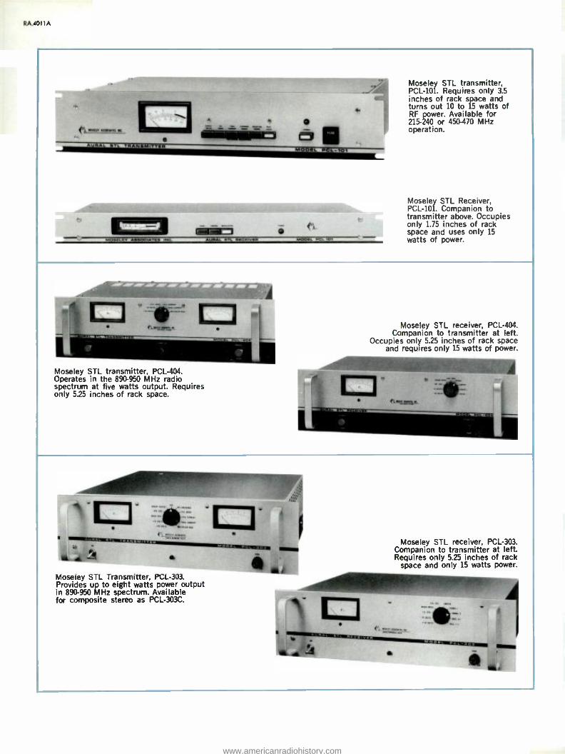
RA.4011 A
MODEL 101
Moseley STL transmitter, PCL -101. Requires only 3.5
inches of rack space and turns out 10 to 15 watts of RF power. Available for 215 -240 or 450 -470 MHz operation.
Moseley STL Receiver, PCL -101. Companion to transmitter above. Occupies only 1.75 inches of rack space and uses only 15 watts of power.
Moseley STL transmitter, PCL -404. Operates in the 890 -950 MHz radio spectrum at five watts output. Requires only 5.25 inches of rack space.
Moseley STL receiver, PCL -404. Companion to transmitter at left.
Occupies only 5.25 inches of rack space and requires only 15 watts of power.
Moseley STL receiver, PCL -303. Companion to transmitter at left. Requires only 5.25 inches of rack
space and only 15 watts power.
Moseley STL Transmitter, PCL -303. Provides up to eight watts power output in 890 -950 MHz spectrum. Available for composite stereo as PCL -303C.
www.americanradiohistory.com

ï M ¡ C 3 N
J1 P ri P n ? CO
Ó .- r ? Ó Ó P
3 R" R" R ñ R" a`rív R
i 1
E
N
0 p N VI N N
p p
N N
g3 iá g á i Ci á3 i { p
!I; et E
E 3 I
m - n C1f m - nÑ /
a i ^
m '- ^
E
m
3 P z. P P^ ^ P
S ñ n m m
ñ n m ri
ñ W
Ñ n
ñ n aa n
1f C1 Ñ n n
ñ aa
z
I
V
` 3
f OIr 0n - f o - 8 0 _
gv o -
W p $ 1 o
M1 1 ÿ íS 1
n >°
3 =R _
a3 R _
R
_
S
R
aS R _
33 RR ñ _
úéCQx
W ev
_o 0 ++
ó _o
++ ó +
ó +
o_ 0 ++
00 ++
ó +
v i ~a
SS ó ó
tgi gi 1 1
SS $ « g g
S 2 2 2 ígi °
SS ó p
í9i g 1 1
S2 2 ó
° ó S 2 í4i
iii ñ I
2ñ 1 1 1 1
r á § -.2
pQvq
I 1
pgvy}
I 1
S yp I
ppvy}
I
Qyagp
I I
py
Iv S Ñ x
qq +I +1
§ § it +1
¢I ó +1 +I
QI 1qóp
+1 +1
1p1q
N +I
1p
+I
Ç
3= +1 +1 +1 +1
n
+1 fl
nn
+l +1 f31 +1
n
+1
Óç m $á
mN Ad
a Jm ^ ^n ^d ñ I
9 SS SS 1 2 2 sa 2
u g
at W
°
at -é aV YYI
g A
à .t,á 0 Si Si
Ask
è d 0 IÁ
è h o M11
g
à ce d I Si
00
ò è nm ai ai
í1f1 Ñ
Ask
X o eyyi
n
V
3 r I N
e y 9 n
+I il Ñ h A
y e 9 9 n ln
+I f1
Ñ M
A A
e m v 9 n n +I + fl ñ 0 á
çW
W
W p
W d W
*W sÑ p ° tt:
¢ i
y e v v n n 171 ^ Ñ
R0
CO 9° n v + ++I +171
^ n
RA
y C n Ti
1 0
i ?
f
E
W
W2 *Ñ w- Ff
^ W -
W
O 2.
G u m d W F N W W
g_...
ñ if
W
W
`7
2 sI
Q
i
U g g t J
1
s 4 2 d Ó W j y *W W
a N
J f ii p 1
y
E i r I V do so > W
1
ú rWÑ
V
r W
= Zs
E
2 F N To
5
1
ii
1
íi Ñ
1
V
W >
yVI at
I
I) W >
fi 3
i n o 1l a 41 ea iw ,o m m 'w1 1 l'1 1 Pl I P I VI P P
B m m N °m pp
C
O Ip O IP O .p O YI a
N tV N {V N N t`1 tj N
; <á Q< CO CO << <4 1 CN CI
S CD en en g' N N Ñ2 ^ ^ Ñ
I I 0
Ñ Ñ ^ Ñ .- Ñ m co - aa m ^^ m
i Flo .°- P p P^ A
= ñ ñ ^ n ñ Ñ ñ ñ Ñ Ñ ñ a0 co m n m .- n n ap
i
ii e
; í9i . í4i í4i í9i gj
$ $g 2 ° g$ ñ9
_ = >
3 9 ñ S RS S3 gQ 0 2í
RR R _ R RR RR .n.
p Og n g ¡ O m O O 0 ++ ++ + } }+ ++ +
=1 = === a
a co
88 88 8 8n 88 88 § WI NI
O O O ç Og O O O O O
q Oq
qOq
+I +1 +I +I +1 +1 +1 +I +I +I +I
r SR SR S S SR SS S U@) @ U @ U@ @@ @) N N N ^ N N ^ n N no no n R no nS n
Z
jN y
t C.-W I
1 1 1 E
N1
N N NI N
g - I
la n:- aIó
N G
W
ins ims im ZN ins i <d pa,,u p_ u p_ pU o- u pUu W s d W s 6 W s W d W s d W d 6 IOjI ! Ñ W ! Ñ W * Ñ * W * ÿ W * W W * Ñ
g-W Kn NQ(N ÓC Ñ Ñ Ñ Ñ IO~t
i if «i f i iii i
RA.d011 A
www.americanradiohistory.com

RA.101 I A
t K
=
I
ú r:
rg W
ú l I ( E
2`
Y
V
W
3 < V
E
g
; 1
u Ñ
V
_ ea s
=
;
á 3
N n
^ P P
- N ro.
É = R++ R °
E
i
C A í7i í4i N
; g R R
= 8 ^ 2 ^ & s ^ ^
1
E_
0
O ^
^ ^ ^ ; ^ ^ ^ ^
- = f N
.O N . O
;
E
L
ÿ 33 '1aV
2G ñ 2G2
33Q vFiñ'c
1 go
C »
6 N^ R ^
° N ^^ ^
° 9 N N^ ^- R ^
y 3 3 n
I ÿ ó 2
m
a 2
I
m 7 é ó ó ó
T
v °$ a "
S 2 °
I
á 2 R
á S 2 2 R R
py Qq Qp pq
-- 1 +I
1 I
g 8 +I tl
ÿ p .. +I +I +I +1
¡r ' .-. é03 6
^ d g
Ñ
g d
ti 1n
W F
3 i V
S F
Z'La Ñ1 Ñ S1 e g
C C
{ 8 C
è CI
ó O n
K
É
ó N
à K C1
É - ó g_ N
iï $
s : a m 9 N
+yyI
O
2
CO V v1
+I
N n A 11
CO m 9 9 v f +I 71
Ñ O 1p
R p
19
S
B
* Y:
Cp
L .1
G
W
Ve
< W°1 xW
W
YF
` ` W W
U s ñ <°` i Wg O á W 1- f f y j ro= O
1 1 f
úi F 1 W
ú I 4 I u W W » W V ola s
1
V
ñ E oal o- u I 4 I V
W > ú é1
I
ú
to
ú
U : 1
a W
etú
x
a W > Ú .
I
ú
¡ ou
V 3 z U
> Q
1
a ; ÿd n 1 a
oi n n oi
a .0 CO
C =,
E
= i
G 2 of N N N
á i 3
I v ñ Ñ '
CC
O
E G
p O ñ Ñ O m m
ii ? o 0. 0.
x ^ ñ ñ ñ co ro- t
f
K o.
é
g 1 ig
1 1 1
á >
S R RS R h R _ ^
^ ^
li 3' O.
+ + ++
¡
N a
n n ., P P vl
r f Ñ
Y : : +I +I +I +I
r^ ä X Ñ
ç gg
§Q óQ
Q 8
T, +I tI tI
t F
Sii
on
U & U U 1. 1, O O O O
IW = Ç
a
i ¡ i # i
W í2i1
C C
W W W
U 5;
= n = -. = á 7
tl°s tl° ON2,-, iW I° aW
O ^ A
K Ó Ñ
?n ii I 12
Marti STL transmitter, STL-8. Typical in appearance of all Marti STL and RPL trans- mitters. Available for 148 -174, 215 -240, 300-340, 450 -470 and 942 -960 MHz bands.
Marti remote -pickup transmitter. Four audio inputs and a multi -purpose front -panel meter. Available for 150 -172 and 450 -470 MHz bands.
Marti STL /RPL receiver R -200. Typical in appearance of all Marti STL /RPL receivers. Companions to transmitters pictured above. Requires 8.75 inches of rack space.
Moseley RPL transmitter, RPL -3 or RPL -4. Identical in appearance, the two Moseley RPL transmitters are available for the 148 -174 and 450 -470 MHz bands. Equipped with two low -level inputs.
www.americanradiohistory.com

RC/1
AM -FM Coaxial Transmission Line
Wide selection of style and size
High efficiency and minimum VSWR
Precision -mated rigid -line flanges
Rigid and semi -rigid
Economical installation
catalog RA.5011A (Replaces B.6200)
RCA coaxial transmission line is an efficient means for transferring transmitter power to AM and FM antennas. Designed with economy, dependability and inexpensive installation in mind, the products described here are available in various nominal diameters and types to accommodate a wide variety of power and frequency requirements. The equipment described includes, elbows, flanges, adapters and other accessories.
www.americanradiohistory.com

RA.5011 A
"Universal" Rigid Transmission Line An RCA exclusive design, "Universal" transmission line features near - perfect reliability and easy, inexpen- sive installation. It is available for radio use in 3- and 6 -inch nominal diameters and in 19.5- or 20 -foot (5.94, 6.1 m) lengths.' Flanges are heliarc welded and use a marmon clamp instead of bolts in a circle. A captive O -ring gasket seals the joint pressure- tight. Installation avoids the radial alignment consider- ations of bolt -flange line because all "Universal" flanges swivel before clamping. Lengths shorter than those above are available on special order.
Universal line inner conductor is sup- ported with polytetrafluoroethylene (Teflon) insulators. Axial support is through an insulator at the flange. Coupling adjacent sections makes the inner conductor captive for axial support.
Bolt- Flanged Line RCA supplies bolt -flanged trans- mission line in steatite- and Teflon - insulated styles for those who prefer this type of connection. Some rigid lines have a rolled groove near one end of the outer conductor. This
200
190
u0
170
ISO
70
60
SO
40
30
20
POWER RATING VS FREQUENCY
140 C AMBIENT; 120 C INNER CONDUCTOR; PRESSURIZED TO I ATMOSPHERE; UNITY VSWR
6i NCN.30 OHM (I -561 37g1
/a NCH, 51.3 OH II-19i1a -1
} 3' /e INCH, 50 OHM, (MI -190 89 M _ 3 U11-27791 Dom=
311M NCH, 51.5 OHM (MI- 19113C 1
I S/a NCH, 50 OHM (MI 561565 )
IN NCMt51.5 OHM (M -19112 )
SS 90 92 94 96 99 100 102 104 106 106
anchors the inner conductor in both axial directions yet provides for inner conductor removal if ever necessary.
Heliax' Semi -Rigid Line Heliax is a semi -rigid transmission line often specified in situations where odd bends and curves abound. The line installs quickly and, if the foam -dielectric type, requires no pressurization. However, FM antenna feed systems often require gas pressurization. When the foam heliax is used with such an antenna, a special pressure -tight tube must be installed along with the Heliax to carry the gas for pressurization to the antenna feed system. In the event of line damage leading to failure, Heliax transmission line repair may require replacement of the entire length as the result of its construction. The segmented design of rigid line allows replacement of individual sections, including elbows.
Transmission Line Accessories A line of adapters and reducers which permit coupling of line components of different configurations is included here. The hanger product line (de- scribed in a separate section) includes fixed and spring hangers
which are available in grounded and insulated versions. There are types for mount on round, or angle -iron tower legs.
Pressurization Equipment Equipment used for transmission line pressurization is described in a separate catalog section. This equip- ment works with dehydrated air or bottled dry nitrogen.
Transmission Line Selection Line selection depends essentially on the frequency and power level of the energy it is to transfer. As one might expect, proper line choice enhances economy, efficiency and longevity, in the long term.
The "Quick Reference Chart" shown opposite lists the broad character- istics of each line style and recom- mends the type of service for each style.
A dimensional layout, on paper, goes a long way in simplifying the planning of the system and, eventually, in ordering the proper components.
FM channels between 97 and 99 MHz require 19.5 - foot lengths; between 99 and 102 MHz require 20 -foot lengths. Channels between 88 and 97 MHz and 102 and 108 MHz use either length.
'Andrew Corp. trademark
www.americanradiohistory.com

RA.501 IA
Elbow Right -Angle, Short End Female
- FEMALE END
LIz
1. , , I
Specially reinforced elbow available as MI- 27791D -2AR. Clamp and gasket included.
Catalog Insert Length Number Ll 1.4
Li
Approx. Packaged Shipping Weight Dimensions Weight
MI- 27791D -2A 814" 4 %," 103/4 lbs. 251/2x13x141/2" 15 lbs. (205 mm) (116 mm) (5 kg) (648x330x368 mm) (7 kg)
Elbow Right -Angle, Long End Female
T - FEMALE END
1:: Qinu' O A
ri Specially reinforced elbow available as Cat. No. MI- 27791D -2BR. Clamp and gasket included.
Catalog Insert Length Number Ll L2
Lz
Approx. Packaged Shipping Weight Dimensions Weight
MI- 27791D -2B 434" 836" 103/4lbs. 251/2x13x141/2 15 lbs. (106 mm) (214 mm) (5 kg) (648x330x368 mm) (7 kg)
Gas Stop
LW Seals pressurized from unpressurized Includes clamps and 0 -ring
Catalog Number
.
...,"- \v..
section. gasket.
Insert Approx. Shipping Length (L) Weight Weight
MI-27791D-3A 4- 27/32" 7 lbs. 10 lbs. (123 mm) (3 kg) (4536g)
www.americanradiohistory.com

RA.5011A
Connector, Inner Conductor
For use with elbows, gas stops and certain adapters.
Catalog Insert Length Approx. Number (Dim. A) Weight
MI-27791D-4D 13/4" 11b. (44 mm) (454g)
Flange, Soft -Solder, Male
h-OUTER CONDUCTOR CUTBACK
Flanges field -cut line.
Catalog Insert Approx. Number Length (t) Length (A) Weight
MI-27791D-4B 1/e" 17/32" 2 lbs. (48 mm) (13 mm) (908g)
Flange, Soft -Solder, Female
OUTER CONDUCTOR CUTBACK
Flanges field -cut line. Catalog Insert Approx. Shipping Number Length (L) Length (A) Weight Weigh
MI- 27791D -4A 23(6" %" 21/2 lbs. 31/2 lbs. (59 mm) (16 mm) (1134g) (1590g)
End Cap, Female Flange
Caps male end of line tempo- rarily to prevent moisture entry. Fitted for gassing and bleeding.
Catalog Number Length (L) Approx. Weight
M I-27791D-8A 274," (62 mm) 21/2 lbs. (1134g)
End Cap, Male Flange
Caps female end of line tempo- rarily to prevent moisture entry. Fitted for gassing and bleeding.
Catalog Number
O Length (L) Approx. Weight
MI-27791D-8B 4" (102 mm) 13/4 lbs. (794g)
www.americanradiohistory.com

RA.5011 A
Adapter, Female to Female Adapter, Universal Female to EIA Flange
Couples female ends of line with two male flanges. Two 0 -ring gaskets in- cluded.
Approx. Catalog Number Length (L) Weight
MI-27791D-7C 12" 5 lbs. (305 m) (2268g)
occaQ4o 9fly7ria
Couples male Universal end to EIA flange (or MI- 19089).
Approx. Catalog Number Length (L) Weight
MI-27791D-7A 6" 7 lbs. (152 mm) (3 kg)
Adapter, Universal Male to EIA Flange
Co) ocooao 71141111,
Couples female Universal end to EIA flange (or MI- 19089).
Approx. Catalog Number Length (L) Weight
MI-27791D-7B 6" 5 lbs. (152 mm) (2268g)
Adapter, Universal Male Cutoff Guides, to Bolt- Flange Inner and Outer Conductor
%4Nb
Q d O r L
Couples female Universal end to bolt - flanged line (MI- 19113C or MI- 19313).
Approx. Catalog Number Length (L) Weight
M l- 27988 -7B 6" 4.5 lbs. (152 mm) (2 kg)
Inner and outer conductor cutoff. Guides that assure square cut.
Approx. Catalog Number For Weight
MI- 19089 -15 Outer 21/4 lbs. MI- 19089 -16 Cond. (1 kg)
Inner 6oz. Cond. (171g)
Miscellaneous
Product Catalog Number
0 -Ring Gasket MI- 27791D -4E V -Band Clamp MI- 27791D -4C
Silicone Grease, 2 -oz. (56g) Tube MI- 19089 -18
www.americanradiohistory.com

Bolt Flanged Transmission Line
Efficient, precision -built line and line accessories. Fea- turing an electrically transparent Teflon insulator, this line uses the familiar bolt -flange connection. Insulator characteristics and precise inner -conductor centering allows cutting and re- flanging in the field without a
change in operating impedance at the cut.
General Specifications Nominal Diameter 31/2 inches Insulation Polytetrafluoroethylene Plastic (Teflon)
Outer Conductor Dimensions: Outer Diameter (3.027" 77 mm ID) 3.125" (79 mm) Flange Diameter 53{6 " (132 mm)
Inner Conductor Dimensions: Outer Diameter 1.315" (33 mm) Inner Diameter 1.231" (31 mm)
Characteristic Impedance 50 ohms
Catalog Number Series MI -19089
Line Sections
Shipped two sections per package. Each section includes one captive anchor insulator- connector, expansion joint, 0 -ring gasket, six bolts, nuts, lockwashers.
4b
Al.- INNER CONDUCTOR CUTBACK
Catalog Dimension Approx. Package Shipping Number Length (l) A Weight Dimensions Weight
M l-19089-1E 20' 1'/B" 60 lbs. 248x13x8" 162 lbs. (6.1m) (29 mm) (27 kg) (6300x330x203 mm) (74 kg)
MI-19089-1F 19'/2' 1'/B" 57 lbs. 240x13x8" 158 lbs. (5.9m) (29 mm) (26 kg) (6096x330x203 mm) (72 kg)
www.americanradiohistory.com

RA.5011A
Elbow, Right Angle, Female
Reinforced elbow available as MI- 19089 -2CR. If anchor insulator connectors required, use MI- 19089.10A. Both flanges swivel.
L2
1(
11173:1
Catalog Insert Length Approx. Number L1 1.2 Weight
MI-19089-2C 43/4" 8" 11 lbs. (111 mm) (203 mm) (5 kg)
Elbow, Right Angle, Male
Equal length legs, both flanges swivel.
Elbow, Right Angle, Tandem
All flanges swivel. Includes one 0 -ring gasket, two captive connectors, twelve bolts, nuts, lockwashers.
Catalog Number LI = 1.2
Approx. Weight
MI-19089-2A 4A" 13 lbs. (105 mm) (6 kg)
Catalog Number
Dimensions L1 /L2 A 6
Approx. Weight
MI-19089-6 4t/e" 71/2" 33/4" 23 lbs. (105 mm) (190 mm) (95 mm) (10 kg)
www.americanradiohistory.com

RA.5011A
Gas Stop
i I
pressurized capped
a
f we N.P.T.
im.
I.= CD @,-
line sections from unpressurized. ports for pressure connections.
Approx. Insert Length (l) Weight
Connector, Anchor Insulator
41.....'"'.7."'' P
ii 1 CI ° `II
1
(MI- 19089) line.
Approx. Weight
i-
Seals Has four
Catalog Number
ffillg7.
Joins inner conductors of
Catalog Insert Number (Dimension
A
bolt -flanged
Length A)
MI- 19089 -10A 13/4" (44 mm) 1 lb. (454g) MI- 19089 -4 Pe (48 mm) 7 lbs. (3.2 kg)
Flange, Mechanical
.
Flange, Soft Solder
Flanges field -cut
Catalog Number
1763mm)
A -yI
Flanges field
Catalog Number Insert
r I OUTER .- CONDUCT
CUTBACK OR
-cut line. No swivel.
Approx. length (A) Weight
/e "122mm1
line. Not pressure- tight.
Approx. Weight
MI-19089-14 1/4" (6 mm) 3 lbs. (1400g) MI- 27988 -4C 3 lbs. (1400g)
www.americanradiohistory.com

RA 5011A
Adapter, "Universal" Vs" Male
0 O Adapts bolt -flanged (MI- 19089) or EIA flanged line to
"Universal" female flange.
Catalog Number Insert Length (L)
Approx. Weight
MI-19089-25 6" (152 mm) 5 lbs. (2300g)
Adapter, "Universal" 31/e" Female
Complement to MI- 19089 -25 (left). Adapts bolt -flange to "Universal" male flange.
Catalog Number Insert Length (L)
Approx. Weight
M I-19089-24 6" (152 mm) 7 Ibs. (3200 kg)
Reducer, 15 /8" EIA Flange
Reduces 31/4 inch flange (MI -19089 or EIA) to 1% inch (EIA) flange.
Catalog Approx. Number Weight
MI-27988-5C 3 lbs. (1360g)
Reducer, 7 /8" EIA Flange
(MITI Reduces 31/21 inch flange (MI- 19089) to 7/9 inch (EIA) flange.
Catalog Approx. Number Weight
MI-27988-5D 3 lbs. (1360g)
www.americanradiohistory.com

RA.5011A
Reducer to Type N Fitting
f 4w. ,
Connects 3,18 inch flange (MI -19089 or EIA) to a Type N female connector.
Catalog Number Length
Approx. Weight
MI-19089-17 8" (203 mm) 53/4 lbs. (3 kg)
Reducer, Type HN Connector
311141.14
Connects 31/2 inch flange (MI -19089 or EIA) to a Type HN female connector.
Catalog Number Length
Approx. Weight
MI- 19089 -21 7%" (187 mm) 4 lbs. (1800g)
Adapter, Inner Conductor
MI- 27988 -4A adapts inner conductors of MI -19089 line to inner conductors of MI- 19113C; MI- 27988 -4B adapts MI -19089 to MI- 19313C inner conductors.
Catalog Number
M I- 27988 -4A M I- 27988 -4B
Dimension A Approx. Weight
1.136"(28 mm) 1.232" (31 mm)
6 oz. (171g) 6 oz. (171g)
Adapter, Male -to -Male
TYYDA, CD Connects male flanges of MI -19089 and EIA components.
Catalog Number Insert Length (L)
Approx. Weight
MI-27938-7E 6" (152 mm) 51/2 lbs. (2500g)
www.americanradiohistory.com

10
6B /EFFICIENCY CONVERSION CHART ATTENUATION - DB
.2 .s 4
::
.6 '100
100 EFFICIENCY I %1
A ANTILOG (IOÓO)
WHERE: a ATTENUATION IN DECIBELS PER 100 FEET 131m1 OF LINE, LENGTH OF LINE IN FEET (0.3048m1
90
40
1.5 2
ATTENUATION - 0e 25
99
9s
97
96
95
94
93
92
91
u
90W
e9 4
8S
e7
as
es
61
83
82
BI
'80 35
RA.5011A
0.24
0.23
0.22
0.20
0.19 E
H1 - 0.1a Ó C1
0:
á 0.15
ó
ZO 0.1
0.13 La
a 0.10
ATTENUATION AT FM FREOUENCI ES
t \tEMI -1 "H21
Isn 5Iß OHM
St
NCH
1-
65 OH
1151
O 0.09
_-.....1__
INCH, SO HMTEFLON 1909 9i 277910; 27T91K
I l MI-11_...--1
0.06
0.05
0.04 es
6 Vs (INCH 515 OHM ST EATI i
l
90 *2 94 96 102 104 ros
1
loe
19314
SO
FORHEQM UTEENFCLOY
M27792 ¡19387, 6I579N
N MEGAHERTZ
61/s
Nominal Recommended Coupling Pressure Power Rating Effi- Wgt /100 Catalog Catalog Diameter Service Device Tight 1 MHz' 100 MHz ciency Lbs /kg Number Page No.
RIGID 50 -OHM IMPEDANCE -TEFLON INSULATED 15/3" FM, VHF -TV Unflanged No 28.5 á v 115/52 MI- 561565 RA.5011 31/s" AM, FM, TV Universal Yes 94 Z G Z. d 280/127 MI- 27791D RA.5011 31/3" AM, FM, VHF -TV Unflanged No 94 c ó c á 230/104 MI- 27791K RA.5011 31/3" FM, TV Bolt Flange Yes 94 °áa ° . 270/122 MI -19089 TR.23012 6148" FM, VHF -TV Unflanged No ñ ° Ñ 625/284 MI- 561579 RA.5011
RIGID 51.5 OHM IMPEDANCE- STEATITE AND TEFLON INSULATED 1543" AM, FM Bolt Flange Yes 1543" AM, FM Unflanged No 3143" AM, FM, VHF -TV Bolt Flange Yes 31/3" AM, FM Unflanged No 3143 "* AM, FM, VHF -TV* Bolt Flange* Yes* 31/e "* AM, FM, VHF -TV* Unflanged* No* 6143" AM, FM, VHF -TV Bolt Flange Yes 61/2" AM, FM, VHF -TV Unflanged No
Teflon insulated.
25 25 94 94 92 92
288 288
v a, d ='o m as v ó
Eñ
crr
a
= x OP
U C . C In
SEMI -RIGID 50 -OHM IMPEDANCE -POLYETHYLENE INSULATED 142" AM, FM Continuous{ Yes 10.0 C 7/8" AM, FM Continuous:, Yes 44.0 2 C a,
1543" AM, FM Continuous{ Yes 145.0 3" AM, FM Continuous{ Yes 320.0 Cá a 5" AM, FM Continuous Yes 830.0 Ñ
SEMI -RIGID 50 -OHM IMPEDANCE -FOAM INSULATED 1441,
1/2" 7/e"
1543"
AM, FM AM, FM AM, FM AM, FM AM, FM
Continuous{ No 5.0 Continuous' No 8.0 Continuous' No 19.0 Continuous, No 44.0 Continuous:, No 145.0
125/57 MI -19112 TR.24012 120/54 MI -19112 TR.2401- 250/113 MI- 19113C RA.5011 265/120 MI- 19113C RA.5011 255/115* MI- 19313C* RA.5011 240/109* MI- 19313C* RA.5011 730/331 MI- 19314C TR.2401 695/316 MI- 19314C TR.2401-
c Z d ÚC
pr á atd a) 7 1.0
U1 aa3 Z 5 at
U
C f/) Uf
27/12 53/24
104/47 178/81 330/150
7/3 12/5 18/8 44/20
130/59
'In kW at 100% modulation, unity VSWR. Available at any RCA Broadcast Field Office or Transmission Line Marketing, RCA Bldg. 2 -2, Camden, N. J. 08102.
3 Attachable connectors available.
HJ4-50 RA.5011 HJ5-50 RA.5011 HJ7-50 RA.5011 HJ8-50 RA.5011 HJ9-50 RA.5011
FHJ1-50 RA.5011 FHJ2-50 RA.5011 FHJ4-50 RA.5011 FHJ5-50 RA.5011 FHJ7-50 RA.5011
www.americanradiohistory.com

RA.5011 A
Layout and Installation of Rigid Transmission Line.
A dimensioned layout of the entire trans- mission line run is helpful in selection of line components and fittings. FM -radio systems usually require a "horizontal" run between the tower hase and the transmit- ter as well as a "vertical" run up the tower to the antenna. AM transmission lines terminate at a tuner at the base of the tower. If the AM tower is base -insulated and also supports an FM antenna, the FM transmission line must include an iso- coupler or be quarter -wave insulated from the tower.
Installation Precautions Care is required in handling the various
transmission line components to prevent damage and assure proper installation. Procedures are outlined in "Transmission Line Do's and Don'ts ".
Tower steel must be designed to sup-
port the vertical run in a straight line, and maintain line clearance within spring hanger guide rings under load.
Vertical Run Considerations Provision must be made to accommo-
date the difference in expansion coeffi- cients between the copper of the line and the steel of the tower. This is accomplished by fixing the line at the tower top and "floating" it down the tower on spring hangers, with expansion accumulating at the bottom of the tower.
Generally, only standard lengths should be included in the vertical run except at the top. However, one or two special lengths may be inserted if it permits a
better pattern of hangers. Positions of flanges relative to hangers, guide rings and tower members must he carefully planned to avoid interference as the line moves relative to the tower. Where inter- ference between line flanges and spring
Transmission Line Do's and Don'ts DO'S
1. DO store packaged transmission line in clean dry place to prevent contamination.
2. DO check operation of inner expander assembly and any components suspected of contamination with dirt or moisture.
3. DO cap all unpacked components against the entry of moisture.
4. DO hoist components with connector end up unless component is marked otherwise.
5. DO check the line in the spring hanger guides after each section is installed to insure free movement for expansion. Shimming of guides at tower support may be necessary.
6. DO consult spring -loading dimension chart (in Hangers section) for proper spring tension on expansion hangers and adjust each position on the tower accordingly.
7. DO ascertain that inner conductors of adjacent sections match alignment to prevent inadvertent damage to the connector. Hold top connector insulator in place and see that the insulator is well seated before installing the next section.
8. DO tap outside of universal line Marmon clamps with plastic -faced hammer, all the way around, to seat clamp os it is tightened.
9. DO tighten flange bolts alternately, one side, then the other, before final torquing.
10. DO use torque wrench for final tightening. 11. DO pressurize line immediately following installation.
and maintain 3 lbs /in' (0.2 atm.) at all times. Leaks must be repaired immediately.
12. DO keep ends of transmission line capped during installation. If installation is halted, seal installed line ends and pressurize to at least 0.5 lbs /in' (0.04 atm.) with dry air or nitrogen.
13. DO coat O -ring gaskets lightly with Dow -Corning DC -4 silicone compound to ease assembly.
14. DO check O -ring and its groove for dirt or other foreign material and ascertain that ring is properly seated before flange assembly.
hangers may occur due to a peculiar spac- ing of tower horizontal members, a steel plate may be used to mount the hanger a sufficient distance above or below the flange to avoid such interference.
Ideally, spring hangers supporting the vertical run of transmission line should occur every 10 feet (3.1 m) however minor variations may be used provided an average of one hanger for each 10 feet of line is maintained. The vertical portion of line near the top of the run should be
anchored firmly using appropriate hanger or hangers. Spring -loading charts arc used to set spring tensions of expansion hangers. As finally installed, the line must be ver- tical and free to more in the hanger guides. When installing transmission line, the preferred method is to start at the bottom and work toward the top. Two transmission line series (MI- 27791D and MI- 19089) must be mounted with the anchor insulator of each section at the
DON'TS
1. DON'T hoist coupled sections of transmission line. The stresses involved damage components.
2. DON'T use force when fitting components one to another. If cause cannot be corrected or isn't evident visually, call for RCA assistance.
3. DON'T assemble line components that contain water or condensation.
4. DON'T assemble line components that contain dust, dirt, packing material or other foreign objects. Consult RCA regarding any loose or suspicious material in the line as it is unpacked.
5. DON'T assemble match -marked components unless the marking is clear and understood. DON'T interchange match- marked items. Consult RCA about proper assembly.
6. DON'T install any line component with dust, dirt or grease on insulators.
7. DON'T install line that exhibits any evidence of damage.
8. DON'T attempt to correct defects discovered unless instructed and authorized by RCA to do so.
9. DON'T dismiss rigger until transmission line is completely installed and pressurized for at least 12 hours and the appropriate electrical tests performed.
10. DON'T power the transmission line until the line is known to be dry and pressurized to at least 3 lbs /in' (0.2 atm.).
11. DON'T exceed specified torque for clamp or flange bolts.
12. DON'T use a line flange with evidence of overstress.
13. DON'T use a damaged O -ring gasket. Use a new gasket whenever in doubt. The same goes for Marmon Clamps.
14. DON'T bend elbow components to fit. If leg angle is incorrect, consult RCA.
15. DON'T let rigging equipment damage components. Provide proper protection.
16. DON'T cut tubing without a cut-off gauge and remove all burrs and chips from inside and outside of tubing.
17. DON'T assemble a horizontal run without proper support.
'Check inner conductor expansion ¡oint for an excursion of 0.2 inch (5 mm) travel and in the extended position check for presence of contacting spring through exposed groove on inner conductor. In some lines the contacting spring is not visible in the extended position. Presence of the spring can be determined by inserting a 6 -mil 0.15 mm) thick feeler gauge (0.5 -inch or 13-mm wide) between the tubing inner surface and the connector body outer surface. If spring is present the feeler gauge can be inserted 0.25 inch (6.4 mm). If gauge goes in 0.5 inch (13 mm), spring is missing and line section must not be used.
www.americanradiohistory.com

RA.5011 A
top end. Series MI- 19313, MI- 19113C, and MI -19112 lines must be mounted with the rolled outer conductor insulator -sup- porting grooves at the lower end. In most cases, the elbow which joins the vertical and horizontal runs is a rein forced type.
Horizontal Run Considerations In complex horizontal -line layouts in-
volving elevation and direction changes, care must be exercised not to overstress miter elbows or introduce excessive flexing of the line. Frequently back to back elbows will be required to achieve desired angles.
As shown in the drawing, three -point, horizontal- spring hangers must support the line for the distance specified from the tower base. The line should be secured at the wall of the building using a horizontal anchor plate. Lines should be protected from falling ice.
When installing 51.5 -ohm, 3 %B -înch line (MI -19113 and MI- 19313), the sections in the horizontal run must connect the grooved end of one section with the grooved end of the adjacent section. Sim- ilarly, the ungrooved end of each section must connect with the ungrooved end of the adjacent section. This arrangement anchors the inner conductor in both direc- tions.
Indoor Installation Considerations The indoor part of the transmission line
is normally not pressurized. Therefore, a Cas Stop is required inside the building and unflanged components used between that point and the transmitter.
Purging Moisture from New Line A transmission line installation must be
free of moisture before power is applied. To purge an installed line, vent the line at the uppermost flange or port. Admit dry nitrogen at the transmitter end. Once purged, lines should be continuously pres- surized with nitrogen or dry air. After any complete loss of pressure, the line should be purged before it is used again.
NEITHER THE BUILDING NOR OTHER THAN 3 -POINT HORIZONTAL SPRING HANGER SHOULD BE PLACED CLOSER THAN 15 FEET (4.6m ) FROM THE LOWEST ELBOW; THIS DISTANCE IS INCREASED 2.5 FEET (762mm) FOR EACH 100 FEET (30m) OF VERTICAL-
... RUN IN EXCESS OF 200 FEET (61m ).
TO TOP, FACE OR LEG -MOUNT ANTENNA THROUGH AT LEAST TWO ELBOWS.
REDUCER (IF REQUIRED)
FIXED HANGER (S)
TRANSMISSION LINE
n
INSTALL EXPANSION HANGERS. SPACE APPROX. IO' (3m) APART.
ALLOW EIGHT FEET (2.4m) FROM ELBOW TO FIRST VERTICAL HANGER FOR EXPANSION OF LINE FROM BUILDING. IF BUILDING IS MORE THAN IOO FEET (30m) FROM TOWER BASE , CONTACT RCA FOR THIS DIMENSION.
HORIZONTAL ANCHORS
HORIZONTAL SPRING ROLLER OR SWIVEL HANGER. SPACED 10 FEET (3m) APART.
...IO FT. (3m) APPROX.,.
fA
LATERAL BRACE 90' ELBOW
www.americanradiohistory.com

R A.501 1 A
"Universal" Transmission Line
imik J General Specifications Nominal Diameter 31/2 inches
Insulation Polytetrafluoroethylene Plastic (Teflon)
Outer Conductor Dimensions: Tube Outer Diameter (3.027" 77mm ID) 3.125" (79 mm) Flange Diameter 4.531" (115 mm) Clearance Hole Diameter (with Clamp) 7" (178 mm)
Inner Conductor Dimensions: Tube Outer Diameter 1.315" (33 mm) Tube Inner Diameter 1.231" (31 mm)
Characteristic Impedance 50 ohms
Catalog Number Series MI- 27791D
Line Sections
Catalog Number Length (l)
Shipped two sections per package. Each section in- cludes connector, clamp, ex- pansion joint and 0 -ring gasket.
Dim. A
MALE END FLANGE
MALE END
Universal transmission line uses a unique, error -proof coupling flange. There are no flange bolts; instead, a single, stainless -steel V -band clamp surrounds the beveled edges of the heliarc- welded, male and female flanges. This holds the flanges in complete alignment. The O -ring gasket is captive in a groove built into the male flange. This arrangement precludes an improperly seated gasket and hence, a leaky joint. Each Universal line coupling is a swivel joint inherently to eliminate the task of radial alignment during installation. A thick Teflon insulator, recessed in the female flange, supports the inner conduc- tor. This design allows easy removal of the inner conductor whenever appropriate.
TO
A POE MN
L
------ LENGTH MEASURED FRO FEMALE TO MALE END
ra FEMALE ENO
FEMALE END FLANGE A-"I k-7
INNER CONDUCTOR CUTBACK
Approx. Packaged Shipping Weight Dimensions Weight
M1-27791D-1A
M1-27791D-113
20' (6.1 m)
191/2' (5.9)
.090 -0.97
(2.3- 2.5mm)
58 lbs. (26 kg)
52 lbs. (24 kg)
248x121/2x8"
(6299x311x230)
162 lbs. (73 kg)
149 lbs. (68 kg)
www.americanradiohistory.com

RA.5011A
Couplings
Join line sections and components.
Catalog Nominal Length Approx. Number Diameter (Dim. L) Weight
M 1-561565-4A 1s/e" MI-27791K-4A 31/e" MI-565579-4A 61/2"
23/8" (59 mm) 8 oz. (228g) 4" (102 mm) 20 oz. (570g)
41/2" (114 mm) 65 oz. (1800g)
Connectors, Inner Conductor
For joining inner conductors.
L 1
Catalog Nominal Length Insert Length Approx. Number Diameter (Dim. L) (Dim. A) Weight
MI-561565-4B 1%" 2" ',j," 2 oz. (51 mm) (1.6 mm) (57g)
MI-27791K-4B 3'/8" 21/2" )fb" 3oz. (64 mm) (1.6 mm) (85g)
MI-561579-4B 31/2" 1;6" 8 oz. 6'/e" (89 mm) (27 mm) (227g)
Adapter, Unflanged 15 /e" to EIA Flanged 15 /a"
Converts unflanged MI-561565 to 1% -inch EIA flanged components using coupling (MI- 561565 -4A) not supplied.
L 1
Catalog Approx. Number Length (L) Weight
MI-561565-7A 41/2" 11/2lbs. (114 mm) (681g)
Adapter, Unflanged 31/e" to EIA Flange
Flanges unflanged 31/2-inch (MI- 27791K) line. Not pressure tight.
176m )
7/8" (22mm) Catalog ' Approx. Number Length (L) Weight
MI-27988-4C 3" 21/2lbs. (76 mm) (1100g)
Adapter, Unflanged 31/e" to "Universal" 31 /e"
Provides Univer- sal (MI- 27791D) male flange on MI- 27791K line. Not pressure tight.
Catalog Approx. Number Length (L) Weight
MI- 27791K -7B 25/e" 21/4 lbs. (66 mm) (1000g)
www.americanradiohistory.com

RA.501 I A
Adapter, Unflanged 31/8" to "Universal" 3V /e"
Ca slog Number
Provides Universal (MI- 27791D) fe- male flange on MI- 27791K line. Not pressure tight.
Approx. Length (L) Weight
MI- 27791K -7A 21/2" 31/2 lbs. (63 mm) (1400g)
Reducer, Unflanged 31 /e" to Type N
Adapter, Unflanged 61 /e" to Bolt- Flanged 61/2"
i`_1 88858 Flanges unflanged 61/2 -inch (MI- 561579) line to mate with 51.5 ohm bolt flanged line. Not pressure tight.
Catalog Approx. Number Length (L) Weight
MI-561579-7A 3%" 8 lbs. (93 mm) (3.6 kg)
Reducer, Unflanged 1s /e" to Type N
Converts unflanged 1% inch line (MI- 561565) to a female Type N Connector.
Catalog Approx. Number Weight
MI-561565-5B 8 oz. (227g)
Reducer, Unflanged 6t /e" to VA" EIA Flanged
Catalog Number
Converts un- flanged 31/2 -inch line (MI- 27791K) to a female Type N connec- tor.
Approx. Weight
MI- 27791K -5A 41/4 lbs. (2 kg)
Reduces un langed 61/2 -inch 50 ohm line (MI- 561579) o 31/8-inch EIA flanged 50 ohm line (MI- 19089).
Catalog Approx. Number Length (L) Weight
MI-561579-5B 63/4' 9 lbs. (171 mm) (4 kg)
Reducer, Unflanged 31 /e" to Unflanged 15/e"
I 1-
Reduces unflanged 31/e inch line (MI 27791K) to unflanged 1% inch (MI- 561565). Requires couplings (MI- 27791K- 4A and MI- 561565 -4A), not included.
Catalog Approx. Number Length (L) Weight
MI-561565-5A 5" (127 mm)
31/4 lbs. (1.5 kg)
www.americanradiohistory.com

RA.5011A
Reducer, Unflanged 61 /e" to Unflanged 31/2"
Transformer -Adapter, Unflanged Adapter, Inner Conductor, 15/e" 61/8" to "Universal" 61/8"
-- L
Reduces un langed 61/s inch line (MI- 561579) to unflanged 31/2 inch line (MI- 27791K). Requires coupling MI- 27791K- 4A (not supplied). Coupling for 61/2 inch end included with two clamps.
Catalog Approx. Number Length Weight
MI-561579-5A 63/4" 8.5 lbs. (171 mm) (3.8 kg)
Transforms 6112 inch 50 ohm (MI- 27791K) to 61/2 inch 75 ohm (MI- 27792D) and pro- vides Universal female flanges. Specify channel or frequency when ordering.
Catalog Approx. Number Length (L) Weight
MI-561579-61 52" 32 lbs. (12m) (max.) (17 kg) (max.)
Adapter, Inner Conductor, 31 /e"
-1- i 231"
1,===tio
H.875" H
Couples inner conductor of 31/8 -inch 50 ohm line (MI- 27791K) to the inner con- ductor of 31/4 -inch 51.5 ohm line (MI- 19113C or MI-19313).
Catalog Dimension Adapts Approx. Number A To Weight
MI-27988-4A 1.136" MI-19313 6 oz. (28.9 mm)
MI-27988-4B 1.232" MI-19113C (171g) (31.3 mm)
Adapter, Inner Conductor 61/8" 50 ohm to 61 /s" 51.5 ohm
L -111
Couples inner conductor of 50 ohm line 62 inch, MI- 561579, to the inner conduc- tor of 51.5 ohm 61/e inch, MI- 19314C.
Couples inner conductor of 1% inch 50 ohm line (MI- 561565) to inner conductor of 1% inch 51.5 ohm line (MI- 19112).
Catalog Length Dimension Approx. Number (L) A Weight
M I-561565-8A 2" 46" 2 oz. (51 mm) (1.6 mm) (57g)
Clamps, Coupling
Catalog Catalog Length Dimension Approx. For Coupling Number Number (L) A Weight
1% inch (MI- 561565 -4A MI- 561565.4C MI-561579-8A 3146" 1,4," 12 oz. 31/2 inch (MI- 27791K -4A) MI- 27791K -4C
(81 mm) (27 mm) (342g) 6112 inch (MI- 561579 -4A) MI- 561579 -4C
www.americanradiohistory.com

RA.S011 A
Special Adapters
Reducer, 31/8" EIA to 7 /e" EIA
Used between 31/8 inch EIA or MI -19089 7/e inch EIA flanged components.
- -I25
Catalog Number Insert Length
Approx. Weight
M I-27988-5D 1.25" (32 mm) 3 lbs. (1.4 kg)
Reducer, 31/e" MI- 19113C or 19313 to /e" EIA
Used between 51.5 ohm, 31 /8 inch MI- 19113C or MI- 19313 line & 7/8 inch EIA flanged components. In- cludes two gaskets, six bolts, nuts, lockwashers (for 31/e inch flange). Nuts and lockwashers for 3/41
inch flange included also.
Catalog Number Insert Length
Approx. Weight
MI-27988-5A 1.25" (32 mm) 3 lbs. (1.4 kg)
Reducer, 31/e" MI- 19113C or 19313 to 15 /e" EIA
Used between 31/8 inch line (MI- 19113C or MI- 19313) & 1% inch EIA flanged components.
OO LaFri Catalog Number
Insert Length
Approx. Weight
MI-27988-5B 0.88" (22 mm) 8 oz. (227g)
Semi -Rigid Transmission Line
Reducer, 15 /e" EIA to 7 /e" EIA
Used between 1% inch EIA flanged to 7/e inch EIA flanged components. Includes two gaskets, seven bolts, nuts, lock - washers.
111.1 0111 - aso'
1
Catalog Number
\I\ t0
, `'° 0
o to ® Insert Approx.
Length Weight
M l-27988-5E 1.75" (44 mm) 3 lbs. (14 kg)
Heliax* is a semi -rigid coaxial cable suited to AM and FM power transmission. Its limited flexibility is the result of cor- rugated copper conductors. It is available in either 50 or 75 ohm impedance (only 50 ohm data included here). Semi -rigid line is of lighter weight than rigid, flanged line and, in some situations, less sus- ceptible to damage than rigid line of comparable size. The line is available with either an air dielectric or filled with polyethylene foam. Sizes range fron an instrumentation type 1/4 inch (6 mm) to a five -inch (127 mm) line with a high - power rating.
*Andrew Corporation Trademark.
www.americanradiohistory.com

R A.501 1 A
Adapter, 51.5 -Ohm
G o O
Adapts MI -19089 and EIA components to 51.5 -ohm (MI- 19113C or MI-19313).
Catalog Number Insert Length (L)
Approx. Weight
MI-27988-7A 6" (152 mm) 51/2 lbs. (2500g)
End Cap
CD MIA For temporary closure of incomplete line installation to prevent entry of moisture. Includes plug for gas bleeding or pressurization.
Catalog Number
Approx. Weight
M1-19089-26 3 lbs. (1.4 kg)
Cutoff Guides
*\,:t
Inner and outer conductor guides that assure square cut.
Catalog Number
MI-19089-15 M1-19089-16
For Approx. Weight
Outer Inner
2.3 lbs. (1100g) 6 oz. (171g)
Miscellaneous
Product Catalog Number
Gasket, 0 -Ring MI- 19113C -10 Kit, Hardware (6 Bolts, Nuts, Lockwashers) MI- 19113C -19 Tool, Lancing MI- 19089 -29 Extractor, Anchor Insulator MI- 19089 -20 Anchor Insulator Expansion Joint
(Field Replacement Kit) MI- 19089 -23 Inner Conductor (20' length). For use with
Expansion Joint above MI- 19089 -99 -1
Grease, Silicone, 2 oz. Tube MI- 19089.18
www.americanradiohistory.com

Steatite Insulated 51.5 ohm Transmission Line
Steatite -insulated line is a 51.5 ohm line useful in AM and FM operations. Steatite is a fired ceramic insulator with a long history in power transmission. Steatite - insulated lines are available only in flanged styles in two nominal diameters: 3V8 and 6 %8 inch. Only the 3%8 inch diameter is listed here because of its suitability to radio operations. Some components from the Teflon -insulated (MI- 19313) series are compatible with steatite -insulated products. These Teflon components are described on the four pages following these two.
General Specifications Nominal Diameter 31/e inches
Insulation Steatite Ceramic
Outer Conductor Dimensions: Tube Outer Diameter (3.027" 77 mm ID) 3.125" (79 mm) Flange 53f," (132 mm)
Inner Conductor Dimensions: Tube Outer Diameter 1.200" (30.5 mm) Tube Inner Diameter 1.136" (28.9 mm)
Characteristic Impedance 51.5 ohms
Catalog Number Series MI- 19113C
Line Sections
Shipped two sections per package. Use MI- 19113C -1SF (swivel flange) for field replacement only. Channels between 97 and 99 MHz require 191/2 foot (5.94m) sections (special order only).
P" 13/32 OUA. HOLE 3/8 -16 X 1.1/2 BOLT
Catalog Approx. Package Shipping Number Length (L) Flanges Weight Dimensions Weight
MI-19113C-1 20' (6.1m) 2 Fixed 53 lbs. (24 kg) 248x13x81/2" 150 lbs. (68 kg) M I-19113C-1 N F 20' (6.1m) None 52 lbs. (24 kg) (6300x330x216 mm) 148 lbs. (67 kg)
Elbows, Right Angle 111
r
Flanged elbow uses swivel flanges and includes inner- conductor connector, O -ring gasket, six bolts, nuts, lockwashers. Unflanged elbow in- cludes inner -conductor connector only.
L,
Catalog Insert Length Approx. Package Shipping Number LI L2 Weight Dimensions Weight
M I-19113C-18 37/e" 8t/e" 111/4 lbs. 121/2x121/2x7" 14 lbs. (98 mm) (206 mm) (5 kg) (317x317x178 mm) (6 kg)
MI-19113C-18NF 3/e" 8t/e" 61/4 lbs. 10x6x4" 7 lbs. (98 mm) (206 mm) (3 kg) (254x152x102 mm) (3 kg)
www.americanradiohistory.com

RA.5011A
Coupling,
0I
Unflanged
, k
,
,.....,,
woo 4 vow. 0,
Inner Conductor, Splicing
$
INNER CONNECTORS (BULLETS) \
I.
_ \\
: r - - - -
INNER CONDUCTOR
Oversize inner- line when cut insulators. Each ner- conductor
Catalog Number
SPECIAL INNER CONDUCTOR
conductor tube for splicing at point other than midway
splice requires two MI- connectors. (Not supplied,
Dimensions ID OD Length
MI- 19113C between
19113C -11 in- see below.)
Approx. Weight
I- 4"
Couples unflanged line sections and components. MI- 19113C -8NB Inner connector.
Catalog Insert Approx. Number Length (A) Weight
MI- 19113C -8B 3(," 11/a lbs. (5 mm) (567g)
MI- 19113C -8NB V(s" Ws lbs. (5 mm) (510g)
MI- 19113C -9 1.136" 1.282" 12' 121/2 lbs. 29 mm) (33 mm) (3.7 m) (6 kg)
Connector, Inner Conductor
Mil A
Adapter, Inner Conductor
"Ili Er
-.9]5'- 1--- j !3z - P 11 36" i 231-
Connects inner conductor of MI- 19113C line to inner conductor of MI -19089 line components.
Catalog Approx. Number Insert Length Weight
2e
Joins inner conductors of MI -19113 components at joints or splices.
Catalog Approx. Number Length Weight
MI-19113C-11 21/2" (64 mm) 2 oz. (57g) MI-27988-4A 7/6" (22 mm) 6 oz. (171g)
www.americanradiohistory.com

PA501 I A
Teflon- Insulated, 51.5 ohm Transmission Line
Teflon- insulated 51.5 ohm line is available in flanged and unflanged styles and features a "wristband spring" inner -conductor expansion joint that prevents galling and contamination of the insulation.
General Specifications Nominal Diameter 31/8 inches
Insulation Polytetrafluoroethylene Plastic (Teflon)
Outer Conductor Dimensions: Tube Outer Diameter (3.027" 77 mm ID) 3.125" (79 mm) Flange Diameter 51/6" (132 mm)
Inner Conductor Dimensions: Tube Outer Diameter 1.282" (32.8 mm) Tube Inner Diameter 1.231" (31.4 mm)
Characteristic Impedance 51.5 ohms
Catalog Number Series MI -19313
Line Sections i Inner conductor connector included with MI-19313-INF. Use MI- 19313 -1SFH or MI- 19313 -1BSFH for replacement only. Chan- nels between 97 and 99 MHz require 191/2 foor (5.94 m) sections (MI- 19313 -1BH or -1BSFH).
Catalog Number Length (L) Flanges
Approx. Weight
MI-19313-1H 20' (6.1m) 2 Fixed 51 lbs. (23 kg)
M I-19313-1NF 20' (6.1m) None 48 lbs. (22 kg)
M I-19313-1SFH 20' (6.1m) 1 Fixed 52 lbs. (23 kg) 1 Swivel
MI-19313-1BH 191/2' (5.9m) 2 Fixed 48 lbs. (22 kg)
M I-19313-1BSFH 191/2' (5.9m) 1 Fixed 48 lbs. (22 kg) 1 Swivel
-L
unu 006 OH% HOLE
3/8 -16 X I -1/2 BOLT
Package Shipping Dimensions Weight
149 lbs. 68 kg)
143 lbs. (65 kg)
248x13x81/2" 150 lbs. (68 kg) (6300x330x216 mm)
147 lbs. (67 kg)
148 lbs. (67 kg)
www.americanradiohistory.com

RA.5011 A
Elbows, Right -Angle
Flanged elbow uses swivel flanges and includes one inner - conductor connector, one inner -conductor -connector adapter, one 0 -ring gasket, six bolts, nuts, and lockwashers. MI- 19313- 2R is a reinforced version of the MI- 19313 -2. Unflanged elbow includes one inner- conductor connector and one inner -con- ductor- connector adapter.
Catalog Insert Length Number L1 L2
MI-19313-2 81/2" Re" (216 mm) (98 mm)
MI-19313-2NF 8" 33/4" (203 mm) (95 mm)
Approx. Package Shipping Flanges Weight Dimensions Weight
2 Swivel 111/2 lbs. 121/2x121/2x7" 14 lbs. (5.2 kg) (317x317x178 mm) (6 kg)
None 61/2 lbs. 9 lbs. (3 kg) (4 kg)
Coupling, Unflanged
Couples unflanged line sections and components. Omits inner connector.
Catalog Insert Approx. Number Length (A) Weight
MI- 19313 -8 3f6" 13/4 lbs. (5 mm) (567g)
MI- 19313 -8NB 3f6" 11 lbs. (5 mm) (510g)
Adapter, Inner Conductor
1.232 -
-__-7--._.,_____ - _
Connects MI -19313 inner conductor to that of MI -19089 or EIA flanged line com- ponents.
Catalog Insert Approx. Number Length (L) Weight
MI-27988-4B /8" 6 oz. (22 mm) (171g)
Connector, Inner Conductor
CIM 5
-I !A
For joining inner conductors of MI -19313 transmission line sections.
Catalog Insert Approx. Number Length (A) Weight
MI-19313-9 2 oz. (1 mm) (57g)
www.americanradiohistory.com

PA S 1 1 A
Gas Stop
5' /n
31/2
Seals pressurized section from unpres- surized. Fits MI- 19113C or MI -19313 com- ponents. 0 -ring gasket and hardware (six bolts, nuts, lockwashers) included.
Catalog Insert Approx. Number Length (L) Weight
MI-19113C-5 7/e" 43/4lbs. (22 mm) (3 kg)
Flange, Mechanical
L
Flanges MI-193113C or MI-19313 unflanged line. Not pressure tight.
Catalog Approx. Number Length (L) Weight
MI- 19113C -60 2" 33/4 lbs. (51 mm) (1.5 kg)
Flange, Soft- Solder
Flanges field -cut Ml- 19113C or MI -19313 line.
Catalog Insert Approx. Number Length (A) Weight
M I-19113C-55 3/4" 3 lbs. (6.4 mm) (1.4 kg)
Guides, Cutoff
Inner and outer conductor cutoff guides that assure square cut. Inner guide shown.
For Approx. Catalog Weight Number
MI-19113 5oz. Inner (143g)
MI -19313 6oz. Inner (171g)
M I- 19113C -9 5oz. Inner (143g)
MI-19113 l0 oz. Outer (286g)
MI-19313 l0 oz. Outer (286g)
M1-19113C-54
M I-19113C-51
M I-19113C-54
MI-19089-15
MI-19089-15
Reducer, 15/g Inch Flanged
L
Reduces 31/s -inch (MI- 19113C or MI- 19313) line to mate with 1% -inch (MI- 19112) line.
Catalog Insert Approx. Number Length (L) Weight
M I-19113C-6 5-5/32" (131 mm)
5.6 lbs. (3 kg)
Reducer. 7e Inch EIA Flange
- L
Reduces 31/e-inch (MI- 19113C or MI- 19313) unflanged line to mate with 7/e inch EIA flanged components.
Catalog Insert Approx. Number Length (L) Weight
M I-27988-5A 13/4" 8 oz. (32 mm) (228g)
www.americanradiohistory.com

RA.5o11 A
Reducer, 15/8 Inch Unflanged
L
Reduces 31/2 -inch (MI- 19113C or MI- 19313) unflanged line to mate with 1%-inch (MI- 19112) unflanged line.
Catalog Insert Approx. Number Length (L) Weight
M I-19113C-7 7" (178 mm) 3 lbs. (1.4 kg)
Reducer, Type N
Converts unflanged (MI -19113 or MI- 19313) line to a Type N female coaxial connector.
Catalog Number Length
Approx. Weight
MI-19113C-58 4 lbs. (2 kg)
Bushing, Adapter
Reduces inner diameter of MI -19313 in- ner conductor to mate with MI -19113 component inner conductors.
Catalog Approx. Number Length (L) Weight
MI-19313-11 14f8" 2 oz. (33 mm) (57g)
Adapter, Inner Conductor
219/32
Connects inner conductors of MI- 19113C line with those of MI -19313 line.
Catalog Insert Approx. Number Length (A) Weight
MI-19313-10 1/8" 4 oz. (3 mm) (114g)
End Cap
Temporarily caps open ends of line (MI- 19113C or MI- 19313) to prevent moisture entry during installation.
Catalog Package Approx. Number Dimensions Weight
MI- 19113C -13 6x6x41/2" 141/4 lbs. (152x152x114 (6.5 kg)
mm)
www.americanradiohistory.com

RA.501 I A
Unflanged, 50 ohm Transmission Line
Unflanged line is a hard tempered cop- per transmission line designed for unpres- surized indoor applications in AM and FM. It employs a low loss Teflon dielectric and operates with high efficiency. A com- plete line of components in I Ye -, 31- and 6'/8-inch nominal diameters provides in- stallation versatility for a wide power range.
Outer Conductor Dimensions: General Specifications Outer Dia. 1.625" (41mm); 3.125" (79mm); 6.128" (168mm)
Inner Dia. 1.527" (38mm); 3.027" (77mm); 5.981" (152mm) Nominal Diameter 1%; 3%; 6% inches Characteristic Impedance 50 ohms Insulation Polytetrafluoroethylene Plastic (Teflon) Catalog Number Series MI- 561565; MI- 27791K; MI- 561579
Line Sections
rismiampia , 1 =,E1
INNER CONDUCTOR CUTBACK A
Each section 20 feet long (6.1m)
Catalog Nominal Dimension Approx. Package Lengths Shipping Number Diameter A Weight Dimensions Per Package Weight
MI- 561565 -1A 1%" 0.015" 25 lbs. 81/2x13x248" 6 203 lbs. (0.39 mm) (11 kg) (216x330x6299 mm) (93 kg)
MI- 27791K -1A 31/4" 0.215" 52 lbs. 81/2x13x248" 2 148 lbs. (5.4 mm) (24 kg) (216x330x6299 mm) (67 kg)
MI- 561579 -1A 61/s" 0.71" 67 lbs. 10x10x248" 1 112 lbs. (18 mm) (30 kg) (254x254x6299 mm) (51 kg)
Elbows, Right -Angle
Catalog Number
Nominal Diameter
Dimension 11 L2
L1
Approx. Weight
MI-561565-2A MI-27791K-2A MI-561579-2A
1%" 31/2" 61/a"
6" (151 mm) 8" (205 mm)
12" (305 mm)
274," (62 mm) 33/4" (95 mm) 6" (152 mm)
23/4 lbs. (1.3 kg) 6 lbs. (2.7 kg)
211/2 lbs. (9.7 kg)
www.americanradiohistory.com

RA.501 I A
4000
000
io
10.
0.1 :
.06
400
100
o . s
0.11
.01.
.004
POWER CURVES 50-OHM AIR DIELECTRIC HELIAX AT UNITY VSWR
mumilliiimmouniumwounimmmullit =1111111111111111=1111111111111111111
11IIIIII1111IIII11111IIIIIIIIIII E. 11..ú ú i i i1111.11..i i:i i i i i i:::1-..:Ú:: 1M.......IIM....MU..IMMM....u. M...MM....uI MMICII1111111MINNIMI M III I 1= .11111 MIIMII II 4/6:1111/1MIlllIM11111MIIIII 111\!11111ìi1111111111111111111111 ,1H1úúú1 .. a.-n=::::: r
F " :::: - nn... :n::m::.... u
:m :iii. 9....1 -______: .....c\MM W
BD ..11 .....1M....11.11 .. \ 8.......1........1 M.1111 B :E1 -..11..1111
MIIIII\511111 rrZMIII1111 sIllllmI1111 111111!!. ' ̀ PIIIII 41111111!!=III11111
1111111111111a1111ii 61110111111111111 11111111 -- -... ..:: %,%=:-::: ''''.."===.1::::: iìi ii: -::::: ::: 1.iiaii ....:: --....11 ---.M..11 _ :.---...1 MMM.Ou11 rY f\..ERIIII . .W11ì.1MW..111 Illll IIllll 4; IIIIIMIIIIII =111111I= 1091 lil11111011111111
111111111111111I1111111111111 ___::::::=--_:::::----- _...--- ... ....1I1......11---::::::::::: --...111 .... M.. 5.1 IM.....11 _---....I I --I11111MEIMIIIIMMIIIIIMIIM.1.111 III
RATINGS BASED ON IIllll `MIllll
ALIMENT TEMPERATURE
I VSWR 1.D 111111111101111
! INNER CONDUCTOR TEMPERATURE.. 100'C 12012 F I IIIIIII1111III1 - PRESSURE, DRY AIR I ATM. C-:Y:'=:: - \-11...::::: Mmm--..... r---.. B.. ...-.Fa.M.....I M.IM MM. ..1.1 --...MITIMMMM..M.111--....1111--....111 10
I ...709
FREQUENCY IN MEGAHERTZ
ATTENUATION CURVES 50 -OHM, AIR DIELECTRIC HELIAX AT UNITY VSWR
10000
ImmIlllllmII1111m..IllllmII1111 11111 I 11111I 1111111 WW1 IIIIII I 1111111 111111E11111111
====EEEEE=-=EEEEEB==-== ::::111::::: MM.MM.IIIMMMNII MI11111nI11 111 11II1I
E1:EEEEE .111..I ::::: L1t
_ . lrIMMUIII atB a ft a.1 II11111
/1 :1
p,
ttls ,1A11111I L``t 111
f`° 1iM 11111111 . . -====:::--,-----r....- .a........ :':: .
ta'1A/ft1a.. I50- t C. a -ESS1.9..ii:::: .11a/att .= ftt
d°'` /.: 'I.....1
1 iiiiiril; I!; , Ea`
l'`` 1111./%11111P11111 IU!i/i1111II
:...::::: 1111III
II'I!Amu.' /.%ÌI .111..iaii1111...- Mi...u1MMM- %IIIII i 11 "° L!' 1Ul_/1_1II11
EEa f iTl:i " at 111/ta
NIIoM1 s,
.1 s° wF...u. `
Pw. .` %::!0*'
.il.MMM.M11111 111111IIIIII 1'l M 1111!11'
MEN U. Ia°_``a,,D.°-N
ti HI 11111111 ii::lr yA
1,0.0. 'IpO f`t ..ÌE.11
.R MI/...A. _'I/ .1111 _,_1_1_I11I
Illll CURVES BA$EO ON'
VSWR_ . 1.0 m AHOLUTETDRY AíRR PRESSURE 1IATM.
1I
MP,In _,_/._'__'I I
FOR TS-OHM CABLES. ::: MULTIPLY VALUES SY 0.95 1.1
1E1
-_-_.:::-_-5' B>8....11111111........1 ..::::8>8..:::1
40
10
.001
O 00 1000 FREQUENCY IN MEGAHERTZ
a i A00. 10000
1000
10o
10
1.0
0.1=
1
.0I
POWER CURVES 50 -OHM FOAM DIELECTRIC HELIAX AT UNITY VSWR
. .
uun1::: i i: i :: : ... ::::-M..::-. i :-...:: ....n u -MM.M..n l MMIIII.MMIIIIIIIIIMMM..111 IIIIIIllll1111111111 IIM1111111=1111111111111111111111111111 \I IIIIIII111111I I I I1111111I I III IIIIIII
3.7=1111 iiiiiáiiiiiiiiiiñ ..111M......11 M.......11111 MM.....11 . A:111 I I I l l l 1111111 1111111 . Illlli111111111111111 1111\:lIIII ' 41 1
.1IIII .II
I
11111111M r.:,"`,lll,1IlIlI.,'IIiIII 7C:.."a C:: C:: : :: :: Eiiiiii 411/..ì.:a mw ..vn.1. ti 'Roull=.uul IIIIII "° `!1111 )ry "D" `RI111IIMIM11111 111111 Mg- F " 1 IIII1IIIIII
11111111111111 ""_Ilnl!_\__1111111 .iiirii.ii::::-..iìi -a.i::i: 1.1.....M..111...M...11..1.......1 1\`......1 MINIM.M1MMEMI.MM.uMI.mlo.M UMI11I Ilull 111111111111111 MIIIIIIIIIM1111111M1111111=`311111 !'11111='1111I1.111911110111111E
RATINGS BASED ON
VSWR.. .. I.0 .....8>r..1..::::: i::::i-11.....u1
AMBIENT TEMPERATURE .. . .. 40C 110.FI 1..11..M.....1 = INNER CONDUCTOR TEMPERATURE.. BOC 1176 F) i;;;ti:::;;;;i - FOR TS-DNM CABLES, MULTIPLY VALUES BY 0.70 I111II11,111111
il11iiii=11imi.1.11IIIII111IIIIIII
1000
Oa
0.1
S.I..ID 1 1. SET.. ,
IIE 100 1000
FREQUENCY IN MEGAHERTZ
ATTENUATION CURVES 50 -OHM, FOAM OIELECTR C HELIAX AT UNITY VSWR
10000
O
_
_....
111111 I I1/41!&d1111/41!&d1111
=-..:::::
8...: : í: _.ul
..M..IUMlmm....II.mm..IIIm6..NI EiInnmmIUU1m.mu1m. 111111
i:::::.1...-i:::::.1.8...:::::..... B1..u..EB1.....uO11E1..u.E.........LV.
111101
.llll
.M11..
1111111 A` ta,ag11III11 :::`,1
ft ' /...O.... -_.... at
1t-..- r._ ._.:::::___ .....EE..... 81MM . tí=t W
N T0°/ I 1/att -OP 01 /
11/111.1.11711117711 I11111 1111111
:::::: B
A IIII ftt`
1 + _
/NM
: , . I::_ -- :EE:1?_ra::::a --.
.1.= I... ., .A11%IM/M.II. 1/1Ì::1 I..iN.11 -IIMI.Sill MUM a ° fY -¡ %I111n %:iNlii //!!IIII B>....::i- .M...!í11../'of MPí111':/" :11!!:
111 ,Rr', °!'íIII/,11111Y1 , i >o' !W tR
Iil;,,11119
IVOi t(a `'Ó 'a:E:B>8...:::Ñ a' MINI IMM=..111
" :: ..I ITM Illl III
I. F.
:;tlOOft` IIIIIII111n 1 1(D 1111111111111I
NOS 1111IIt r°a I1111111
11q11I =_ 1::: ra' -I cuRVES BASED ON _ m::-::: ----B..1I_-..I .MpM.III.M.MM. IIMPE%IIIIIIMIIMII 1111111111
111111
m:; vSWR 1.0 ... AMBIENT TEMPERATURE ..2.CITSFI
foR IB oHY uelfs, YULTTIPLI VALU(S BY
IlÌIIII 111111 IdIII T 100 1000
FREQUENCY IN MEGAHERTZ
10000
100
.01
www.americanradiohistory.com

RA.501 I A
SPECIFICATIONS /ORDERING INFORMATION SEMI -RIGID CO -AX LINE
Nominal Diameter Velocity
1 MHz Power Rating (kW)
Atten- uation
Outside Diameter inches (mm)
Minimum Bend Radius
inches (mm) Weight
lbs /ft kg /m Catalog Number
AIR DIELECTRIC
2" 91.4%
7 /e" 91.6
1 %" 92.1
3" 92.3
FOAM DIELECTRIC 1/4n 79
3/4rr 79
112rr 79
Va" 79
1%" 79
10
44
145
320
5
8
19
44
145
d
ti o. m
f? c
a
d
°iá 2m Ú
N a
0.58
1.11
2.00
3.02
0.29
0.44
0.62
1.09
2.00
(14.7)
(28.2)
(50.8)
(76.7)
( 7.4)
(11.2)
(15.7)
(27.7)
(50.8)
5
10
20
30
2.50
3.75
5.00
10.0
20.0
(127)
(254)
(508)
(762)
( 63.5)
( 95.2)
(127 )
(254 )
(508 )
0.27(122g)
0.53(240g)
1.04(470g)
1.78(807g)
0.06(27g)
0.12(54g)
0.18(82g)
0.44(200g)
1.35(612g)
0.413
8.10
1.59
2.72
0.09
0.18
0.28
0.67
2.06
HJ4-50
HJ5-50
HJ7-50
HJ8-50
FHJ1-50
FHJ2-50
FHJ4-50
FHJS-50
FHJ7-50
lbs /ft x 3.37 Ib /m lbs /m x 0.4536 - kg /m
SEMI -RIGID CO -AX LINE ACCESSORIES
Line Nominal Diameter (inches)
Line Type Number
FOAM DIELECTRIC
sh" s/a" 1/2" 1/2" Ws" FJH1-50 FJH2-50 FHJ4-50 F14J3-50 FHJ7-50
AIR DIELECTRIC
Vz" 7 /e" 1 Ms" 3" HJ4-50 MJS -SO HJ7-50 HJ8-50
UHF Jack (Female) UHF Plug (Male) Type N Jack (Female) Type N Plug (Male) Adapter, End Terminal Elbow, Mitre Wraplock, Stainless Steel Tie Wires, Copperweld Clamp, Mounting, Insulated Flange, EIA Flange, EIA w /Gas Barrier Splice Grip, Hoisting Type LC Plug (Male) Type LC Jack (Female) Kit, Grounding (Copper Line) Kit, Hanger Adapters, Hanger:
Angle Iron Member Round Tower Member
Hanger, Insulated Adapters, Insulated Hangers:
Angle Iron Member Round Tower Member
Barrier, Gas Dehydrator, Automatic Pump, Dry Air Fittings, Nitrogen Tank
41U 41P 41N 41W
13212 -22
12395-1
27290A 11662 -31
42U 42P
42N 42W
13212 -2-
12395 -1
27290A 11662 -31
44AU 44AP 44AW 44AN 44AT
12395- -1
11662 -3
44AR
44AZ
44AM
26892 -2
45AU 45AP 45AW 45AN 45AT
12395 -1
11662 -2
45AR
45AZ
45A- M
45AL 40993-5
31776.5
31768 -1
31670 -s
206- 1
12395 -1
33948 -3 47R
47Z
47M
47L 40993 -2
31776 -2,
31768 -1
31670 -3
74N 74W
12395 -1
26892 -2
11662 -3
13555A
13550
19,20A
878A
85ßC
75AU
75AN 75AW 75AT 1060
12395-1
75AR
75AG 75AZ
19256B
40993 -5
31766 -5,
31768 -1
31670 -3
11662 -2
13555A
13550
1260A 1920A
878A 858C
87N
206- 1
1061
12395-1
87R
87G
87Z 24312A
40993 -2
31766 -2,
31768 -1
31670 -3
33948 -3
13555A 13550
1261B 1920A 878A
858C
2062 1062
78AR- M
78AGM 78AZ 26985A
40993 -11
33598 -3-.
33981 -1
33984 -14
33948 -2
13555A 13550
1262A 1920A
878A
853C
'Clamp for half inch line, shim smaller diameters. *Use with Type N Plug. `Please specify diameter of tower member (1 1-2"; -2 2.3 "; -3 - -- 3 -4 "; -4 -- 4 -5 "; -5 5-6"). 'For 1.3" tower legs; for 3 -4" legs, use 41108.1; for 4.5 ", use 41108 -2; for 5-6" legs, use 41108 -3.
`Kit contains hangers only. lower adapters required. See "Adapters, Hanger" listing.
www.americanradiohistory.com

Transmission Line Hangers and Accessories
For vertical support
For horizontal support
Rigid and expansion
For indoor or outdoor use
catalog RA.5021A (Replaces B.6200)
Described here are hangers for 31/2 inch rigid transmission line. They can be supplied for vertical and horizontal runs and for indoor as well as outdoor use. Insulated types permit support of lines on insulated AM towers. Parenthetical dimensions in millimeters unless designated otherwise.
www.americanradiohistory.com

RA.502I
Vertical Support
SINGLE, FIXED
Long arm unit (8%") matches standoff dimension of insulated hanger. Use heavy duty hanger (see below) for runs 750' (229 m) and longer. For 31/2 -inch line only.
90 ADJ.
A Dimension Approx. Catalog
L Weight Number
5" (127)
8°4" (217)
11 /2 lbs. (680g) 13 lbs. (794g)
M1-19313-44 MI-19313-47
SINGLE, EXPANSION
Long arm unit (89S6 ") matches standoff of insulated hanger (see below, left). For 31/2 -inch line only.
Dimension Spring Approx. Catalog L Chart Weight Number
5" (127) A 3 lbs. (1.4 kg) MI- 19313 -32
8°ße' (217) A 31/4 lbs. (1.5 kg) MI-19313-33
SINGLE, INSULATED; EXPANSION
Insulated counterpart of MI- 19313 -33 described above. For 31/2 -inch line only.
11011
1
Dimension Spring Approx. Catalog L Chart Weight Number
8N6" (217) A 7 lbs. (3.2 kg) MI-19313-34
FIXED, HEAVY DUTY
Use for runs 750' (229 m) and longer. Dotted lines in drawing are tower members. Mounting details packed with product. For 31/2 -inch line only.
=Pi
Approx. Weight Catalog Number
13 lbs. (6 kg) MI-19313-41
www.americanradiohistory.com

Horizontal Support
SWIVEL, SINGLE
Accomodates some horizontal line expansion, but no vertical movement. Use three point suspension unit (see below) when length of vertical run or line stiffness requires vertical as well as horizontal movement of the horizontal run. For 31/4-inch line.
Dimensions A 6 C D
Approx. E F Weight
Catalog Number
2-17/32" 2z/e" 11/4" 5" 1/2" .74¡' 3 lbs. MI-19313-37 (53) (73) (28) (127) (13) (11) (1.4 kg)
SUSPENSION, THREE POINT SINGLE For 3's -inch horizontal line only.
- EvE BOLT 6- LONG
2 "E rE BOU e 6LONG
Dimensions A
Approx. Weight
Catalog Number
203/4"
(527)
15" (381)
51/4 lbs. (2.3 kg)
MI- 19313 -50
ROLLER, HORIZONTAL
Supports horizontal line. Use two for dual lines. Mounting bolts not included. Accommodates no vertical movement; uses three -point suspension units for horizontal runs where vertical run length or line stiffness requires vertical as well as hori- zontal movement. For 3112 -inch line only.
D 1
e
I E-IDIA.1 O 11 HOLES1
Dimensions Approx. Catalog A e C D E Weight Number
41/4" 3" 43/4" 8" (108) (76) (121) (203)
7/32" 21/4 lbs. MI- 19313 -35 (6) (1.1 kg)
ANCHOR, HORIZONTAL, SINGLE
For 31/e -inch line only. Supports line at building wall. Use on both sides of wall. Clamp included; bolts not included.
E - I 016.1
C e
-A
w
Dimensions Approx. Catalog A C D E Weight Number
8" 67/e" 3j6" '6" Xi" 31 lbs. MI- 19313 -17 (203) (174) (87) (14) (14) (1.5 kg)
RA.5021
www.americanradiohistory.com

RA.5021
BRACE, LATERAL
Mounts in single hole. Two clamps included. Re- stricts lateral motion while allowing vertical and horizontal movement. For 35/4 -inch line.
Diwonsiews Approx. Catalog A g C Weight Newsboy
73/4" 383/4" 44" 25/ lbs. Ml- 19313 -36 (203) (978) (13) (1.1 kg)
Spring Chart A Distance Below Lowest Fixed Hanger
Feet Meters
0 -20° (- 18 - -7 °)
in. mm
Loaded Length at Ambient in °F ( °C)
20 -40° 40 -60° 60 -80° (- 7 - -4 °) (4 -16 °) (16 -27 °)
in. mm in. mm in. mm
80 -100° (27 -38 °)
in. mm
LOADED LENGTH (SEE CHART) 0- 200 0- 61 15 381 151/4 384 151/4 387 155/4 387 15% 391
200- 400 61 -122 143/4 375 15 381 151/4 387 15% 391 15% 397
400 - 600 122 -183 145/2 368 14% 378 151/4 387 15% 394 15'/4 403
600 - 800 183 -244 141/4 362 1444 375 151/4 387 15% 397 161/4 410
800 -1000 244 -305 14 356 14% 371 151/4 387 1544 400 161á 416
1000 -1200 305 -366 137/8 352 14'/2 368 151/4 387 15'/4 403 161/2 413
1200 -1400 366 -427 1344 349 145/2 368 15114 387 1576 403 16% 422
1400-1600 427 -488 13% 346 14'12 368 151 387 16 406 1644 425
1600 - 1800 488 -549 13/2 343 1441 365 155/4 387 16 406 1674 429
1800 -2000 549-610 135/2 343 144á 365 15114 387 16 406 167/4 429
www.americanradiohistory.com

RCA Pressurizing Equipment: Dehydrators and Gassing System Kits
Choice of two dehydrators
Nitrogen -bottle regulators
Expandable system kits
Flexible plastic tubing
Brass and bronze fittings
catalog RA.5031A (Replaces B.6200)
Described here is equipment and material for the pressurization of flanged transmission line. There are two dehydrator /compressors and three "gassing kits ". The dehydrator/ compressors differ in size and capacity, to accommodate various transmission -line system require- ments. The three gassing kits combine the fittings and components into complete packages that simplify installation.
www.americanradiohistory.com

Heatless Compressor /Dehydrators
Discharge air dewpoint -40
Available in two capacities
Two -cylinder, oil -less compressors
Adjustable outlet pressure
Engineered and manufactured specifically for pressurizing RF transmission lines, these two compressor /dehydrator units differ only in output capacity and physical dimensions. The units deliver dry, compressed air at the rate of one or two cubic feet per minute (0.028 or 0.056 m3).
Oil -Less Compressor Both units use an oil -less, two -cylinder air compressor with
a direct -drive %2- or 3- horsepower electric motor. All operate from 115/230 V, 60 -Hz power (50 -Hz units are available on special order, see Ordering In formation).
"Dry -Pak" Dehydrator The "Dry-Pak" dehydrator provides a continuous supply
of dry air. The dew point of this air is below -40 degrees C. The Dry-Pak dehydrator uses a system of air expansion and silica -gel dessicants to achieve this dryness.
A program timer, within the Dry-Pak, recycles the dessicant as required and entirely automatically. The device includes an
adjustable pressure switch which maintains discharge pressure at any level between 1 and 15 lbs. /in2 (0.07 -1.05 kg /cm2). The switch is factory set for 4 to 7 lbs /in2 (0.28 to 0.49 kg /cm2).
Maintenance -Free System Dry-Pak Compressor Dehydrators require no routine main-
tenance. After many hours of use, the Teflon piston rings of the compressor might need replacement to restore the unit's pressure capability. These are available as spare parts.
Specifications Output Air:
Dewpoint -40° C
Pressure 1 -15 lbs /in2 (0.07 -1.05 kglcm2)
Volume: Half- Horsepower Unit 1 ft3/min. (0.0283 m3 /min.) Three -Quarter Horsepower
Unit 2 ft3 /min. (0.0566 m3 /min.)
Input Air: Temperature 125° F (52° C) max.
Relative Humidity 0-100%
Power Requirements 1151230 V, 60 Hz or 115/230 V, 50 Hz
Pressurizing Capacity 1%" Line 31/2" Line We Line 93(6" Line
Half- Horsepower Unit (1 SCFM) *....10,000' 2500' 700' 250'
(3048 m) (76 m) (213 m) (76 m) Three -Quarter
Horsepower Unit (2 SCFM) *..40,000' 10,000' 3,000' 1000'
(1220 m) (305 m) (914 m) (305 m)
Dimensions Half- Horsepower Unit 20" H; 22" W; 15" D
(508, 558, 381 mm)
Three -Quarter Horsepower Unit 28" H; 22" W; 15" D
(711, 558, 381 mm)
Weight Half- Horsepower Unit 95 lbs. (43 kg)
Three -Quarter Horsepower Unit 117 lbs. (53 kg)
Ordering Information Heatless Compressor /Dehydrator (115/230
Half- Horsepower Unit Three -Quarter Horsepower Unit
V 60 Hz: M I-563170-1
MI-563170-2
Heatless Compressor /Dehydrator (for 50-Hz power)
Half- Horsepower Unit MI- 563170 -1A
Three -Quarter Horsepower Unit MI- 563170 -2A
'SCFM = -- Standard cubic feet per minute.
www.americanradiohistory.com

Gassing System Kits
For one- to eight -line systems
For dry air or dry nitrogen
Precision needle valves
Highly flexible PVC tubing
Gauges included
Gassing Kit "A" Kit "A" provides the fittings,
tubing, valve and gauge required to pressurize a single transmission line from a compressor /dehydrator or a regulated source of com- pressed dry nitrogen.
6616.0A
SO VEST
TO SAS
i1i4 40 OC2110
PUSIAATOP OP 0(MTPRATOP
4 o o,.,,
rrcri o w W.
°u° °u° f I 4
® ; to3pU ̀[ö [rs6. I ZS
L(;)10.111"
® PLASTIC TOSISO
°óo.eós[.6.a,.,, Y -56.M9 56 666[
There are three gassing system kits: an "A" kit which is basic to Kit "B" which, in turn, is basic to Kit "C ".
Accessories Single -Stage Pressure Regulator (See photo below) For use where bottled dry nitrogen is the pressurizing
source instead of dehydrated compressed air. Connects between nitrogen flask valve and gassing system input fitting MI-19315-22
Plastic Tubing For situations where the tubing included in Gassing Kits "A"
and "C" is insufficient for requirements. In 50 -foot (15.2 m) coils MI- 561668A -1
Ordering Information Gassing Kit A MI- 561668A Gassing Kit B MI-561668B Gassing Kit C MI- 561668C
Gassing Kit "B" Kit "B" expands the load capa-
bilities of Kit "A" to handle a dual T/L system. It includes an eight -port manifold and the valve, gauge and fittings required for the additional transmission line. The kit includes no plastic tubing on the basis that surplus is available from Kit A. Should additional tubing be required, it is available separately, see Accessories.
Gassing Kit "C" Kit "C" expands the capabilities
of Kit "B" by one. It includes a valve, a gauge, 25 feet (7.6 m) of plastic tubing and the fittings necessary to connect a Kit A and a Kit B to an additional transmis- sion line. Thus, if the system uses four pressurized transmission lines, it should be equipped with one Kit A, one Kit B and two Kits C. It is important to note that, to use a Kit C, Kits A and B must be available.
www.americanradiohistory.com


Ron Coaxial Transmission Line Switches
Low VSWR
Maximum isolation
High reliability
Manual and motor -driven types
catalog RA.5041A
Coaxial transmission line switches provide convenient, rapid and reliable switching of rf power circuits. Standby transmitter changeover, emergency antenna selection, dummy load connections, temporary by- passing of components, and many other functions are readily accomplished.
Switches for either manual or powered switching accommodate different sizes and types of rigid lines and single- or multiple -line power transfer. They maintain high reliability, maximum isolation and low VSWR.
www.americanradiohistory.com

RA.5041A
Motor Driven Coaxial Switches The motor driven 31/4-inch coaxial
switch, MI- 561562, is a simple but ex- tremely versatile component that provides reliable and fast switching of r -f energy between coaxial lines with control from a remote point.
Completely compatible with standard coaxial line components, the switch may be used as a four -port transfer switch or a three -port single -pole, double -throw switch. This versatility lets the switch serve a variety of switching situations.
Specifications
Electrical Operating Frequency Any to 900 MHz Characteristic Impedance 50 or 51.5 ohms Power Rating Identical to T/L used VSWR
50-220 MHz 1.05:1 or less 450-900 MHz 1.03:1 or less
Insertion Loss 0.05 dB or less Isolation (50 -880 MHz) 60 dB or more Switchover Time (nominal) 2 seconds Drive Motor:
Voltage 115V -! --10% Frequency 50/60 Hz Current:
Start 2.OA Run 0.48A
Current Rating of Auxiliary Relay Contacts ........15A, 250Vac
Mechanical Dimensions see drawing Weight .
65 lbs. (28 kg)
Reliability is an outstanding feature of this switch. The mechanical drive is
simple and the number of moving r -f conductors is at a minimum so that op- erations in excess of 100,000 cycles arc possible without failure.
MTG. HOLES FOR we BOLTS. TYP. 4 PLACES
1200" (305mm) CENTERS
TYPICAL ADAPTER SECTION
TRANSMITTER A
TRANSMITTER
A B
SWITCH
C D
COMBINER
B
SWITCH
2 -
A BO
SWITCH S
OC Dp
DUMMY LOAD
REJECT LOAD
HARMONIC FILTER TO ANTENN
TYPICAL SWITCHING SYSTEM (SWITCHES EITHER MANUAL
OR MOTOR -DRIVEN
Ordering Information
Motor Driven Coaxial Switch . MI- 561562( *)
*Designate suffix letter from Table below:
MI- Designation Transmission Line Type MI- 561562 -A MI- 19089, 50 ohms, flanged MI- 561562 -B MI- 27791 -K, 50 ohms, unflanged MI- 561562 -C MI- 19313 -NF, 51.5 ohms, unflanged MI- 561562 -D MI- 19313, 51.5 ohms, flanged MI- 561562 -E MI- 27791 -D, 50 ohms, male flange MI- 561562 -F MI- 27791 -D, 50 ohms, female flange
Accessory An optional control panel for use with the MI- 561562 Switch is available. It mounts in a standard 19 -inch relay rack and includes an On -Off switch, operating switch and position - indicator lights. Order as MI- 561596.
Note: Contact RCA representative for information about similar switches for other line sizes.
www.americanradiohistory.com

Manual Coaxial Switches RCA manual coaxial switches for VHF
provide a convenient and rapid means of switching r -f power circuits. They utilize standard coaxial transmission line fittings mounted on a panel in a way that switching functions are readily accom- plished by the "patch cord" method. Switches differ in construction to meet the various sizes and types of transmission lines.
Fittings come in 3'/8- or 6%8 -inch sizes
and the switch plugs are constructed of double 3 %8- or 6%8 -inch elbows which form a U section, maintaining line im- pedance throughout the switch. Panels are reinforced with angle bends on all four sides. Holes in the side angles provide
RA.5041 A
for mounting. The 3 -pole switch has one U -type connector, the 4 -pole, two and the 7 -pole, three (see drawings next page). The U- connectors clamp to the fittings. Various connections and impedances are available. See Ordering Information, next page.
Sturdy, reinforced steel bases
3 -pole, 4 -pole and 7 -pole types
Low VSWR
Maximum isolation
Specifications Electrical Power Rating Same as various Transmission Line
to which they apply Ambient Temperatiure To 50° C
Elevation 5000 ft. (1500 m) max. to full power rating VSWR 1.02 to 1 or better
See Ordering Information Impedance
Mechanical Dimensions Weight:
3 Pole, 3'/e" 4 Pole, 31/4" 7 Pole, 31/4" 3 Pole, 6'/8" 7 Pole, 61/4"
See Outline Drawings
(79 mm) Models 32 lbs. (15 kg) (79 mm) Models 52 lbs. (24 kg) (79 mm) Models 67 lbs. (30 kg) (156 mm) Models 75 lbs. (34 kg) (156 mm) Models 220 lbs. (100 kg)
Accessories
31/2" 50 ohm adaptor used to connect straight sections of line to MI- 27912 -50 and 51 MI- 27912 -52
31/4" 51.5 ohm adaptor used to connect straight sections of line to MI -27717 and MI -27718 Ml -27337
61/2" 51.5 ohm adaptor used to connect straight sections of line to MI -27719 and MI -27720 MI -27709
Spare "U" bend, 31/e ", 7" (178 mm) centers for use with MI -27717 and MI -27718 MI -27999
Long "U" bend, 31/4", 14" (365 mm) centers for use with MI- 27912 -51 Switch MI- 561679
INSTALLATION NOTE:
Because of inner conductor considerations, either an elbow or an adaptor component must connect to the several switch ports.
www.americanradiohistory.com

RA .5041 A
u ur CLEW ¢¢
SIZE A B C D
354" 1554" 1355" 7" - 80 mm 393 343 178 - 654" 25" 23" 13" 1154"
156 mm 635 584 330 292
Outline Dimensions, 3 -Pole Panels
/'.
TRANSMITTER
I___ aE: - W/4" u.'
Is uE' L,.
437 DIA
Outline Dimensions, 4 -Pole Panels
SEVEN -POLE SW ITCH
TRANSMITTER
d
LOAD NORMAL
MODE
REJECT LOAD
COAX COUPLER
u
HARMONIC FILTER TO ANTENNA
SIZE A B C D
354" 23" 21" 7" - 80 mm 584 533 178 - 61/2" 38" 36" 13" 18"
156 mm 965 914 330 457
Outline Dimensions, 7 -Pole Panels
A TEST / B AIR MODE
Typical two- transmitter switching system.
LONG -U' BEND I SEE ACCESSORIES)
B TEST / A AIR MODE
d d A
d O d F G C
d d E D
R B TEST MODE
Ordering Information
Stock Identification Diameter Impedance Poles Type Connector For Use with RCA Line
MI -27717 31/4" (79 mm) 51.5 ohms 3 Sleeve MI- 19113 -C or MI -19313 MI -27718 31/2" (79 mm) 51.5 ohms 7 Sleeve MI- 19113 -C or MI -19313 MI -27719 61/4" (156 mm) 51.5 ohms 3 Sleeve MI- 19314 -C
MI -27720 61 /e" (156 mm) 51.5 ohms 7 Sleeve MI- 19314 -C
MI- 27912 -50 3' /e" (79 mm) 50 ohms 3 Inside, Universal MI- 27791 -K MI- 561680 3' /e" (79 mm) 50 ohms 4 Inside, Universal MI- 27791 -K MI-27912-51 3W (79 mm) 50 ohms 7 Inside, Universal MI- 27791 -K
The above are standard designs fitting most requirements. Other configurations to fit special switching requirements are available on special order.
www.americanradiohistory.com

AM -FM Antenna Towers
Wide selection of AM or FM antenna towers
Complete line of tower accessories
Self- supporting or guyed types
Standard or custom designs
catalog RA.6011 B (Replaces RA.6011A)
RCA can make a wide selection of towers available for all AM and FM applications ... including standard self - supporting, guyed and custom designs.
Guyed Towers Where land area permits, towers are
usually guyed and the usual cross sectional shape is triangular so that three point guying can be used. Guyed tower costs are usually lower than for self- supporting structures because less steel is used. A useful method for estimating the land required for a guyed structure is to con- sider the distance to the farthest guy anchorage as being about 80 percent the tower height.
Self- Supporting Towers Self -supporting towers are especially ad-
vantageous in city and congested districts where land is expensive. For estimating required space for a self -supporting tower, the distance between tower legs can nor- mally be considered as 10 percent the height of the structure.
Wind Load Towers must be designed and installed
to safely withstand the maximum wind velocities that may be encountered. Ex- perienced tower builders rarely design for less than a 30/20 -pound loading. This means that the tower members are de- signed to resist a horizontal wind pressure of 30 pounds per square foot of projected
.,.-.,` .. ..
'
}
ti.lr+at.at . !.s... i.:
www.americanradiohistory.com
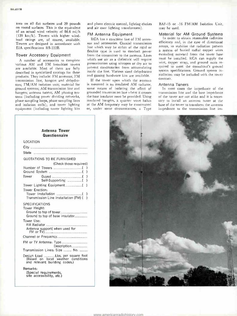
RA.6011B
area on all flat surfaces and 20 pounds on round surfaces. This is the equivalent of an actual wind velocity of 86.6 mi /h (139 km /h). Towers with higher wind - load ratings are, of course, available. Towers are designed in accordance with EIA specifications RS -222B.
Tower Accessory Equipment A number of accessories to complete
various AM and FM broadcast towers are available. Most of them are fully described in specialized catalogs for these products. They include: FM antennas; FM transmission line, hangers and dehydra- tors; FM /AM isolation unit; material for ground systems; AM transmission line and hangers; antenna tuners; AM phasing sys-
tems (including power dividing networks, phase sampling loops, phase sampling lines and isolation coils); and tower lighting equipment (including tower lighting kits
and photo electric control, lighting chokes and air core lighting transformers).
FM Antenna Equipment RCA has a complete line of FM anten-
nas and accessories. Coaxial transmission line which may be either of the rigid or flexible type is used to conduct power from the transmitter to the antenna. Lines which use air as a dielectric will require pressurization using nitrogen or dry air to prevent condensation from accumulating inside the line. Various sized dehydrators and gassing hardware kits are available.
If the tower upon which the antenna is mounted is an insulated AM radiator, some means of isolating the effect of grounded transmission line where it crosses the base insulator must be provided. Using insulated hangers, a quarter wave balun at the AM frequency may be constructed or, under some circumstances, a Type
Antenna Tower Questionnaire
LOCATION
City
State
QUOTATIONS TO BE FURNISHED
(Check those required) Number of Towers ( )
Ground System ( )
Tower Guyed ( )
Self- Supporting ( )
Tower Lighting Equipment ( )
Tower Erection: Tower Installation ( )
Transmission Line Installation (FM) ( )
SPECIFICATIONS Tower Height:
Ground to top of tower Ground to top of base insulator
Tower Use: AM Radiator Antenna support( when used for
FM or TV)
Channel or Frequency
FM or TV Antenna: Type Description
Transmission Lines: Size No.
Design Load Lbs. per square foot (Based on local weather conditions and relevant building codes.)
Remarks: (Special requirements, site accessibility, etc.)
BAF -15 or -16 FM /AM Isolation Unit, may be used.
Material for AM Ground Systems In order to obtain reasonable radiation
efficiency and, in the case of directional arrays, to stabilize the radiation pattern a system of buried radial copper wires extending outward from the tower base must be installed. RCA can supply the wire, copper strap, and ground mats re- quired to meet the consultant's ground system specifications. Ground system in- stallation may be included with the tower contract.
Antenna Tuners In most cases the impedance of the
transmission line and the base impedance of the tower are not alike and it is neces- sary to install an antenna tuner at the base of the tower to transform the antenna impedance to the transmission line im-
www.americanradiohistory.com

pedance. RCA markets a standard group of antenna tuners for low and medium power use. In the higher power range antenna tuning units are custom built.
AM Phasing Equipment Multiple tower AM arrays are used to
achieve specific horizontal and vertical radiation patterns as required by alloca- tion or economic factors related to cover- age. Varying amounts of power at various phase angles are fed to the various towers. RCA is in a position to supply all of the elements of phasing, power dividing, and antenna tuning units. In these multi -tower arrays, methods for sampling the phase and amplitude of the RF voltage in each tower and conveying this sample to the phase measuring equipment located in the transmitter house are required. Accessory phase sampling loops, which are normally mounted on the individual towers, phase
sampling lines to connect the loops to the measuring device, and means for isolating the grounded sampling lines where they cross the tower base insulator are also available.
Antenna Feed Bus The antenna tuning unit output should
he connected to the tower by means of copper tubing which is not normally supplied with the antenna or transmitting equipment. The tubing may be obtained from local sources and should be flattened and drilled at the ends so that it may be connected to the antenna tuning unit output feedthrough insulator and attached to the tower by bolt or brazing. At a point between the tower and the feed - through insulator the line should be formed into a one or two turn coil, 12 to 18
inches in diameter. This coil can be self - supporting and is intended to retard
WIND VELOCITY AND CORRESPONDING WIND PRES- SURE ON TOWERS -EIA STANDARD SPECIFICATION
Actual Wind Velocity
mi /hr (km /hr)
Wind Pressure On Flat Surfaces
(P - 0.004 V=) lbs /ft' (kg /m -)
Wind Pressure On Round Surfaces
lbs /ft- (kg /m -)
Estimated Survival Velocity
(F.S. 1.65) mi /hr (km /hr)
10 16.1 0.4 1.95 0.266 1.29 12.9 20.8
20 32.2 1.6 7.80 1.067 5.21 25.8 41.5
30 48.3 3.6 17.57 2.40 11.71 38.6 62.1
40 64.4 6.4 31.23 4.27 20.83 51.5 82.9
50 80.5 10.0 48.80 6.67 32.55 64.4 103.6
60 96.5 14.4 70.27 9.60 46.85 77.3 124.4
70.7 113.8 20.0 97.60 13.33 65.05 91.1 146.6
80 128.7 25.6 124.9 17.10 83.45 103.0 165.7
86.6 139.3 30.0 146.4 20.00 97.60 111.5 179.4
90 144.8 32.4 158.1 21.60 105.4 115.9 186.5
100 160.9 40.0 195.2 26.70 130.3 128.8 207.2
110 176.9 48.4 236.2 32.30 157.6 141.7 228.0
111.8 179.9 50.0 244.0 33.30 162.5 144.0 231.7
120 193.1 57.6 281.1 38.50 187.9 154.6 248.8
122.5 197.1 60.0 292.8 40.00 195.2 157.8 253.9
130 209.2 67.6 329.9 45.00 219.6 167.4 269.3 132.3 212.9 70.0 341.6 46.67 227.7 170.4 274.2
140 225.3 78.4 382.6 52.33 255.3 180.3 290.1
141.4 227.5 80.0 390.4 53.33 260.3 182.1 293.0
150 241.4 90.0 439.2 60.00 292.8 193.2 310.9 160 257.4 102.2 498.7 68.20 332.8 206.1 331.6
170 273.5 115.6 564.1 77.00 375.8 219.0 352.4 180 289.6 129.6 632.4 86.60 419.7 231.8 373.0
190 305.7 144.4 704.7 96.30 469.9 244.7 393.7
200 321.8 160.0 780.8 106.66 520.5 257.6 414.5
At left -WSBT- AM /FM /TV antenna farm showing WSBT's first television tower and new high -rise guyed TV tower for in- creased coverage. At the far right are the four towers used in the WSBT -AM directional array.
RA.6011 B
lightning and aid in the breakdown at the ball or horn gap provided at the tower base thus keeping lightning discharges from damaging the radio equipment.
Tower Lighting The configuration of tower lights and
the lighting equipment must conform to applicable government specifications. The a -c power required to operate the lights may be conducted on wires which are buried in the ground or carried on the same poles which carry the transmission line from the transmitter house to the antenna tuning unit. The a -c power lines will have to be isolated from the RF power where they cross the base insulator. This isolation can be provided either through the use of an antenna lighting choke and appropriate bypass condensers or by the use of an air core lighting transformer.
Ordering Information
Tower Accessories
8 ft. by 24 ft. (2.4 x 7.3 m) Section Expanded Copper Ground Screen MI -27765
No. 10 Copper Wire MI- 28405 -8
3" by 0.020 (76 x 0.5 mm) Ground Strap MI- 28405 -A4
Double RF Antenna Lighting Choke MI- 7112 -C
Triple RF Antenna Lighting Choke MI- 27726 -A
Capacitor for Lighting Chokes MI- 27728 -1
Weatherproof Housing MI -27741
1750 W Hughey and Phillips Transformer MI- 28215 -Al
3500 W Hughey and Phillips Transformer MI- 28215 -A2
Tower Lighting Kits (Triangular Tower)
Tower Height No. Obstruction Order ft (m) Beacons Lights No.
21'- 150'(6.4 -45.7) 0 1 double (on top) A-1
151' - 300' (46.0 - 91.4) 1 3 at one level A-2
301'- 450' (91.7 - 137) 1 3 at two levels A-3
451' - 600' (137 - 183) 2 3 at two levels A-4
(Lighting Kits include all materials required to light and wire a tower of heights specified, such as original and 100
percent spare lamps, beacon flasher, photo -electric control, color coded wire, stainless steel wraplock tape condulets, locknuts, supporting arms, unions, pipe compound, installa- tion print, and bill of materials in accordance with FCC, CAA and National Electric Code Requirements.)
For other Antenna Accessories, see appropriate RCA Catalogs.
www.americanradiohistory.com

RA.60118
0 a w j` «. c- C
ó ó añu c::a
. -cc In -m d y
V V1 V 0 y7a
E21, aaia ó
tO ... w c a) «a
cNÿ mm- N_ p N - a
3 c co á m O 4
W
ÓEr° EL° - Em
cN C Ñ E cOiJl N1:7 cÿ 00 CO
Nmóÿ N
N u -8
Et `00 OÜ lo N u _ a c-.o °cd
-A..- ío w3u E á ó om
Y1 17 adc m U
Á m tn X N
Ñ -- O pY
m m
cgó O Nw a, O lo
E vÿ 01- E
o-C
www.americanradiohistory.com

I ICA 250W, 1000W Antenna Tuning Units
Custom -built arrangements available for any requirement
Make -before -break switches avoid damage to antenna ammeter from static discharges
Optional remote metering provisions
Specifications Frequency Range 1600 kHz Transmitter Power (maximum) 1 kW Antenna Resistance 20 to 250 ohms Transmission Line Impedance 50 to 230 ohms Antenna Reactance +j200 to -j200 ohms
(Can be extended in the positive direction by the addition of series capacitance and in a negative direction if operated from a transmission line of lower impedance than the antenna resistance at no extra cost.)
800 *kHz to
Low frequency limit may be extended to 540 kHz at extra cost.
catalog RA.6111A (Replaces B.6270)
The RCA Type BPA- Series Antenna Tuning Units provide an impedance match at broadcast frequencies between series - fed, vertical radiators and coaxial or open -wire transmission lines. They also aid in suppressing harmonics.
Four models of BPA -21 1 -kW Antenna Tuning Units are available. They differ only in the type of accessories, such as remote metering or the tower -lighting chokes provided with the units. Remote - meter kits and tower -lighting chokes can be added at any time to the basic MI- 27767A unit. An MI -27725 Antenna Tun- ing Unit, without provision for future addition of lighting chokes or remote meter, is available also.
All models of the BPA -21 and the MI- 27725 include an RF antenna ammeter. Tower height and frequency should be specified on the order to permit deter- mination of the correct ammeter -scale range. The antenna reactance and resist- ance should be specified if the antenna is
other than a base -fed, vertical radiator of uniform cross section.
Height 28!ßa" (714 mm)
Width 221/e" (562 mm)
Depth 163/4" (425 mm)
Weight (Approx.) 65 lbs. (30 kg)
Remote Meter Pick -up Unit (less meter) MI- 28027C
Double Winding RF Antenna Lighting Choke Coil with 2 Capacitors ES -27241
Triple Winding RF Antenna Lighting Choke Coil with 4 Capacitors ES -27242
Double Winding RF Antenna Lighting Choke Coil with 2 Capacitors and Weatherproof Housing ES -27243
Triple Winding RF Antenna Lighting Choke Coil with 4 Capacitors and Weatherproof Housing ES -27244
Informal:; Type BPA -21A Antenna Tuning Unit MI- 27767A
Type BPA -21B Antenna Tuning Unit with Remote Metering MI- 27767B
Type BPA -21C Antenna Tuning Unit with Remote Metering and Two -Wire Lighting Choke MI- 27767C
Type BPA -21D Antenna Tuning Unit with Remote Metering and Three -Wire Tower Lighting Choke MI- 27767D
250/1000W Antenna Tuning Unit (less remote - meter kit and remote meter) MI -27725
(Specify transmitter power, frequency, line impedance, tower height and type. If other than base -fed, vertical radiator of uniform cross section, specify antenna resistance and re- actance.)
www.americanradiohistory.com

Ren 5/10 kW Antenna Tuning Units, Types BPA- 5A / -10A
For co -ax or open -wire lines
Weatherproof housing
Simple, efficient circuit
Built -in current meter lamp
Versatile mounting flanges
The BPA -5A (5 kW) and BPA -10A (10 kW) Antenna Tuning Units match antennas to coaxial or open -wire transmis- sion lines and suppress carrier harmonics.
All parts are enclosed in a weatherproof metal housing with a door. Flanges mount the unit on two upright posts or on a wall. The antenna ammeter is read through a circular window in the door and provision for a lamp to illuminate the meter is in- cluded.
The circuit of the antenna tuning unit consists essentially of a single T- section low -pass filter which reduces the number of elements to a minimum. Two series inductors permit separate adjustments of the transmission line and antenna termi- nating impedances. The shunt capacitors are fixed at values determined by the operating frequency.
An optional remote RF- pickup unit, (MI- 28027C for the BPA -10A; MI- 27966B for the BPA -5A) and a remote indicating ammeter (with a range corresponding to the tower base ammeter) can be added to the tuning units to provide a means of observing the antenna current at a remote location (transmitter house).
The units are custom built to meet customer requirements.
Specifications Frequency Range 540 kHz to 1700 kHz Transmitting Power:
BPA -5A 5 kW max. BPA -10A 10 kW max.
Antenna Resistance: BPA -5 10 to 1100 ohms BPA -10A 20 to 1100 ohms
Transmission Line Impedance 50 to 350 ohms
Antenna Reactance +j500 to -j500 ohms (Can be extended, at no additional cost, in the positive direc-
tion by the addition of a series capacitor, and in a nega- tive direction if operated from a line of lower impedance than the antenna resistance.)
Power Requirement (for lamp) 115/230V, 50160 Hz
Finish Durable gray
Overall Dimensions 41" H, 34" W, 23" D (1041, 863, 584 mm)
Weight (net) 330 lbs. (150 kg)
Accessories Remote RF Pick -up Unit (less meter, 5 kW max.) MI- 28027C
Remote RF Pick -up Unit (less meter, 5-50 kW) MI- 27966B
Double Winding RF Antenna Lighting Choke Coil with 2 capacitors ES -27241
Triple Winding RF Antenna Lighting Choke Coil with 4 capacitors ES -27242
Ordering Information Antenna Tuning Unit, 5 kW, Type BPA -5A MI- 27789A
Antenna Tuning Unit, 10 kW, Type BPA -10A MI- 27790A
(Specify transmitter power, frequency, line impedance, tower height and type. If other than base -fed vertical radiator of uniform cross section, specify antenna resistance and re- actance.)
www.americanradiohistory.com

Ren AM Antenna Phasing Equipment
Individually designed systems
Adjustable under power
Cabineted or open -panel construction
Rotary -adjustable inductors
.020E' 673OE:
ItL'JI
4
catalog RA.6211A (Replaces B.6260)
RCA antenna phasing and branching systems are built to the specific require- ments of each antenna situation. RCA built its first antenna phasor before World War II and literally hundreds of systems carry the RCA monogram. Most systems use the "Jeep- Coil" design although "Ohm's - Law" phasors are available as well.
Where appropriate, RCA equipment uses front -panel- controlled rotary induc- tors to provide independent control of the current to each antenna tower. This affords increased system flexibility. The systems use "lagging -T" networks to phase the currents. The two series legs of each phasing network may be ganged rotary in- ductors with a single front -panel control. Networks provide wide -range, independent phase adjustment for each tower current with precise impedance match. The sys- tem uses series- resonant circuits for econ- omy and stability. All controls can be motorized for remote control.
Tower Impedance Matching Line -terminating units perform the
impedance match between the trans- mission line and the antenna tower.
Reliable Switching Facilities Indispensable for the changeover from
daytime to nighttime patterns, the switch- ing system use positive -latch relays where - ever appropriate in the power- divider networks, the arms of the line terminator units and in the phasor networks. These relays have pilot -contacts which can be wired to lighted status indicators.
Cabineted or Wall- Mounted Units Phasing equipment is available mount-
ed in cabinets that match current RCA AM transmitters or on open panels which are intended for wall mounting. Wall mount provides extra accessibility to the phasor and the line terminators.
When the system is cabineted, the number of cabinets is proportional to the number of towers and system complexity. Most systems, however, fit into a cabinet 44 inches wide, 34 inches deep and 77 inches high (1118 x 865.x 1956 mm).
www.americanradiohistory.com

PHASING S. BRANCHING EQUIPMENT
POWER DIVIDING NETWORKS
TÖb TRANS- MITTER
PHASING NETWORKS
0- <> TRANSMISSION
LI NE
Q <
LINE TERMINATING UNITS
TRANSMISSION LINE
TOWER NO.1
TOWER NO.2
fC'I' lr-n4,; TRANSMISSION
LINE
RELAYS SHOWN IN DAY PATTERN
TRANSMISSION LINE
Typical antenna -phasing schematic diagram.
TOWER NO.3
TOWER NO.4
How to Order RCA quotes price and delivery for phasing systems on
an individual basis. The answers to the questions below provide the information needed for the preparation of a quote:
1. Assigned frequency kHz
2. Operating power: Day kW; Night kW
3. No. of elements in array 4. Element description 5. Element spacing feet 6. Element self- impedance ohms 7. Current required in each element:
#1. A #2 A #3 A
#4 -A #5 A #6 A
8. Phase Angle required in each element:
#1 #2 #3 #4 #5 ° #6
9. Length of transmission line to each element: #1 ft #2 ft #3 ft #4 ft #5 ft #6 ft
10. Characteristic impedance of transmission line (s) ohms
11. Pattern -switching requirements (non -directional day- time; different patterns, night and day; etc.)
12. Cabineted unit desired? Yes No
13. Antenna -current -sampling system preferred-
14. Motorized controls desired? Yes No
Typical tuning unit housed in weatherproof cabinet.
www.americanradiohistory.com

AM Antenna Accessories
Phase sampling loops
Isolation coils for sampling lines
Dummy loads
Antenna ammeters
Lighting chokes
Type C0019 Sampling Loop.
catalog RA.6311A (Replaces B.6272)
Here are devices for monitoring, testing and evaluating the perform- ance of AM- broadcast antenna systems. There are current -sampling loops, isolation inductors, air- and water -cooled dummy loads, meters, meter kits, compensating networks and inductors for tower hazard - lighting systems.
www.americanradiohistory.com

RA.631 1 A
Sampling Loops Shielded or unshielded
Fixed or rotary
Grounded or insulated
Connect to co -ax cable
Sampling loops develop a signal proportionate to the strength of the field which surrounds them. The signal thus developed is used to sample the tower currents and phase angles in an antenna system.
Shielded loops reject electrostatic energy with little reduction in electromagnetic response. Rotary loops allow fine adjust- ment of position for maximum sensitivity and insulated loops allow phase sampling without the need for isolation inductors in the sampling lines.
Shielded, Rotary, Insulated Loop, Type C0019
The Type C0019 provides a sensitive and accurate method for tower- current sampling in directional- antenna arrays. Shielded to eliminate response to electrostatic energy, the loop responds to only the electromagnetic field of the tower to which it mounts. The rotary aspect allows adjustment of the loop for maximum pickup without change in self- impedance. Connection to the co -ax cable is at the bottom pivot. Brackets for universal mount on tower leg included.
Specifications Dimensions 331h" H, 251/2" W (841, 648 mm)
Connector UHF 83-1R
Mating Connector UHF 83 -1SP
Ordering Information Shielded, Rotary, Insulated Sampling Loop,
Type C0019 MI-561522
Unshielded, Fixed, Uninsulated Loop, Type 173 -11 -1
A three -sided loop designed for grounding to the tower leg ( the leg serves as the fourth side of the loop), the type 173 -11 -1
Sampling Loop is constructed of heavily plated steel tubing. Sensitivity is adjusted by the spacing between the outside leg of the loop and the tower. The assembly includes changes and necessary hardware for mounting and for connection of a 70 -ohm, coaxial line. Shipped unassembled with assembly instructions and special assembly tools. (Not illustrated.)
Specifications Dimensions 72" H, 30" W (max) (1829, 762 mm)
Connection .Outer -cond. clamp; inner -cond. strap
Ordering Information Unshielded, Fixed, Uninsulated Loop,
Type 173 -11 -1 MI -27730
Air -Cooled Dummy Loads
Offered in any specified impedance, these inexpensive dum- my loads are available in five power ranges. Wire wound, the loads are slightly inductive. Load reactance compensators, available separately (sec above, right), arc used to offset the inductive reactance in the load, where necessary.
Specifications Frequency Range 540 to 1600 kHz
Power Levels (100% modulation) 500, 1000, 5000, 10,000, 20,000W
Input Impedance As required
Ordering Information Ohm -Spun Dummy Load Type WG
(Please specify power level required and input impedance; loads are built to order.)
Water -Cooled Dummy Loads
Available for either 50- or 230 -ohm systems, these wire - wound loads are packaged in two forms: one, the resistor units mounted in a housing with water inlet and outlet con- nections and, two, in kits that include a water flow- meter, thermometers, valves, hoses, tubing and appropriate fittings for assembly into a load appropriate to the application. Loads require a supply of water of a quality safe for drinking.
Specifications Input Impedance (ohms) 50 or 230
Water Supply Requirement Potable quality Water Flow Requirement (U.S. Gal /min) 8 -17 (30-65 Ilmin) Water Supply Temperature 75 °F (24 °C) max
Ordering Information Water -Cooled Resistor Units:
230 -ohm Impedance MI- 27029 -2
50-ohm Impedance MI- 27029 -3
Water -Cooled Load Kits Assembled to Order
www.americanradiohistory.com

Load Reactance Compensators
Mounted in close proximity to Ohm -Spun dummy loads, these networks offset the small inductive reactance of the load. The networks consist of topped, fixed -value inductors and a
mica -dielectric capacitor. Adjustment requires the use of an RF bridge instrument. Networks are built to order for use with Ohm -Spun loads only. (Not illustrated.)
Specifications Input Impedance 50 or 230 ohms
Power Levels: At 50-ohm impedance 1 or 5 kW At 230 -ohm impedance 10 or 20 kW
Ordering Information Load Reactance Compensator Custom Built
(Please specify power level and impedance)
Air -Cooled Dummy Load.
Isolation Inductor An isolation inductor takes the sampling- current co-ax across
the tower -base insulator from the tower to ground without short -circuiting the insulator. The inductor is essential in every case where the sampling loop is bonded to the tower. The inductor is wound with coaxial cable and is equipped with appropriate connectors as specified by the customer
Specifications Characteristic Impedance (ohms) 50
Mfg. Type Number Connectors Please Specify by
Ordering Information Isolation Inductors:
Jacketed Foam Heliax, r/a" (6 mm) M150- FHJ1 -50 Foam Heliax, 3/e" (10 mm) M150- FH2 -50 Jacketed Foam Heliax, 36" (10 mm) M150- FHJ2 -50 Foam Heliax, '/z" (13 mm) M150- FH4 -50 Jacketed Foam Heliax, r/z" (13 mm) M150- FHJ4 -50
(Please specify connector type number desired)
RA.631 I A
Unshielded, Rotary, Insulated Loop, Type 173 -11 -2
An unshielded, insulated loop with adjustable sensitivity, the Type 173 -I1 -2 allows phase -angle sampling on simple arrays and low- impedance towers without need for an isolation induction. Constructed of plated steel, the loop assembly includes mounting hardware (less U- bolts). Connector for sampling line also included. Unassembled, with assembly in- structions and special tools. (Not illustrated.)
Specifications Dimensions 73" H, 4112" W (1854, 1054 mml
Connection Outer -cond. clamp; inner -cond. strap
Ordering Information Unshielded, Rotary, Insulated Loop,
Type 173 -11 -2 M l -27731
Remote Metering Kits
Remote metering kits include a meter and an RF- pickup unit which, in combination, allow measurement of antenna current at a point some distance away from the antenna system. The RF- pickup unit converts RF current into a low- voltage, d -c current of sufficient magnitude to deflect a one -milliampere meter.
Specifications Pickup Unit:
Sensitivity 3-30A (540 kHz); 1 -30A (1600 kHz) Dimensions 7" H, 73/3" W, 5%" D (178, 188, 137 mm)
Meter: Sensitivity (Full Scale) Case Dimension See list below
Ordering Information RF- Pickup Unit:
For 5 kW Systems (and lower) MI -27966
For 10 to 50 kW Systems M I -28027
Meter (Select to match transmitter meters and specify full -scale calibration):
0.001A dc
Transmitter Type No.
BTA-1R1 BTA-5L/-10L BTA-5L1/-10L1 BTA-5T BTA-50/-10V BTA-5V2/-10V2 BTA-50J BTA-250M BTA-1M, -5G/ H, -10G/ H
Case Dimension
4" (102 mm) 4" (102 mm) 4" (102 mm) 4" (102 mm) 4" (102 mm) 4" (102 mm) 41/2" (115 mm) 3" (76 mm) 4" (102 mm)
Catalog Number
M I-27644A M I-27644A M I-27644A M I-27644A M I-27644A M I-27644A M I-27644B M I-28037 M I-28037B
www.americanradiohistory.com

RA.6311 A
RF Ammeters, Thermocouple Type
Calibrated for mounting in Va -inch steel panels, these RF ammeters are offered for use with antenna phasing systems
that match the transmitter from a styling viewpoint. Some
use an internal thermocouple while others use an external. The thermocouple is included in either case. Available only from RCA Parts and Accessories, Deptford, N.J. Order by
stock number.
Ordering Information
Meters to match BPA -10, -11, -50 Antenna Ammeters:
Meters to match Range 0 -2A 0 -3A 0 -5A 0 -8A 0 -10A
BTA -250M Transmitter: MI (Ref only) Stock Number MI-28048-2 423423 M I- 28048 -3 423424 MI-28048-5 423425: MI-28048-8 423426 MI- 28048 -10 423643
Meters to match BTA -1M, -1R1, -5H, -10H, -5T, -50H: Range MI (Ref only) Stock Number 0 -2A MI- 7157F -2 423396 0 -5A MI- 7157F -5 423398 0 -10A MI- 7157F -10 423399 0 -15A M1- 7157F -15 423400 0 -20A MI- 7157F -20 423410 0-25A MI- 7157F -25 423401
Range
0-2A
0-5A
0-6A
0-10A
0-15A
0 -20A
MI (Ref only)
MI-7147-2
MI- 7147 -5
MI- 7147 -6
MI- 7147 -10
M1- 7147.15
M1. 7147 -20
Stock Number
423414
423416
423421
423418
423479
423420
Meters to match BTA -5U1, -10U1 Transmitters: Range MI (Ref only) 0-2A M I- 7157G -2 0-5A M I- 7157G -5 0-10A MI- 7157G -10 0-15A MI- 7157G -15 0-20A MI- 7157G -20 0-25A M I-7157G-25
Stock Number 423633 423427 423429 423430 423431 423432
Typical Antenna Tower Lighting System diagrams and close -up view of Choke Coil, MI- 7112 -C.
SINGLE CIRCUIT II -MI- 7112 -C)
RF CONNECTION
t INSULATORS
IIIOV. JIM/ lOR2
k VA
POWER SUPPLY
3 CIRCUITS TRANSFER RELAY AT
LOWER BASE WIRE DISTRIBUTION (2 -MI- 7112 -C)
w +a
2 CIRCUITS 3 WIRE DISTRIBUTION
II - MI- 27726)
2 CIRCUITS TOP LIGHT B FLASHER
AT LOWER BASE 3 WIRE DISTRIBUTION
II -MI- 27726)
SERIES RELAY :1-10V1
UMW I OR 2
KVA IIOV
POWER SUPPLY
IIIOV., UMW
I OR 2 k VA
110V
POWER SUPPLY
Tower Lighting Chokes
Used to couple 50 or 60 Hz power to tower hazard lights and minimize dissipation of RF energy into power line, these chokes are double or triple wound on Bakelite forms and coated with an insulating varnish. Used outdoors, the coils must he protected from weather. Any winding not connected to the tower or ground must be bypassed to the tower at the "hot" end and to ground at the "cold" end.
Specifications Current Capacity (max. at 50/60 Hz) 15A Winding Res:stance (Approx., each winding) 0.15 ohms Inductance (at 1 Mhz) 360 pH Dimensions 11%" L, 4" Dia. (295, 102 mm) RF Power (max.) 5 kW
C.
C.
RF CONNECTION
INSULATORS
L_ FLASHER
I,I,,O,,V., 11 C IOR2
'K VA IIOV.
POWER SUPPLY
Accessories Weatherproof Housing .
MI -27741
Bypass Capacitor, 0.01 pF MI- 27728 -1
Ordering Information Lighting Choke, Double Winding MI -7112C
Lighting Choke, Triple Winding MI -27726
Lighting Choke Kit, Double Winding (1 Choke, 2 Capacitors) ES -27241
As above with weatherproof housing ES -27243
Lighting Choke Kit, Triple Winding (1 Choke, 4 Capacitors) ES -27242
As above, with weatherproof housing ES -27244
www.americanradiohistory.com

RC/1 AM Antenna Phase Monitors, Types AM -19 (204), PM -19
Two to twelve towers, entirely self- contained
Analog or digital readout
Ratio resolution: 0.1 percent
Pushbutton tower selection
All solid state electronics
catalog RA.6411A
An integrated system to fulfill the antenna monitoring requirements of any AM array of two to twelve towers, the Type AM -19 (204) makes no compromise in monitoring. The monitor is available with analog or digital readout, with or without remote readout. (The "204" in parentheses in the type number indicates the FCC approval number.)
For situations where extra precision and measurement repeatability is important, the PM -19 System is offered. This system uses the AM -19 (204) with an adapter that increases precision significantly.
!fa
fC
.
I am
www.americanradiohistory.com

R A.641 1 A
Analog Readout Phase Monitor, Type AM -19 (204) Absolute accuracy: 1 degree
Loop current accuracy: 2 percent
Long -life, mercury- wetted relay contacts
Pushbutton tower selection
Entirely maintenance -free
The AM -19 (204) provides an absolute phase measurement accuracy of plus -or- minus one degree with a one -half degree resolution. Loop current indications are ac- curate to within 1.5 percent with a resolu- tion of one -half percent. The meters are individually calibrated to assure a tracking accuracy of one -half percent and minimize error introduced by variations in meter
characteristics within production toler- ances. Modulation on the carrier has no effect on phase measurement.
Easy Operation Pushbutton switches permit tower sam-
ple selection in any order, without need for a special sequence. The phase -angle meter is calibrated in degrees to eliminate
Specifications Operating Frequency Range 150 to 2000 kHz Phase Angle Range (Lead or Lag) 0 to 180 degrees Phase Angle Accuracy ±1 degree Phase Resolution 0.5 degree Current -Ratio Range (of reference) 0 to 110 percent[ Current Ratio Accuracy ±1.5 percent Current Ratio Resolution 0.5 percent Available Patterns DA -1 (DA -N), DA -2, DA -3 Number of Towers 12 max. RF Input Impedance 50 or 72 ohms2 RF Input Level 0.5 to 20 Vrms Input Connector(s) Type UHF 50-239 Input Level from Ref. Tower
(For 100% loop current reference) 2Vrms min. Analog Outputs (Local and Remote):
Phase (0-180 degrees) (Adjustable) 0 to 5Vdc Loop Current (0-100 percent) (Adjustable) 0 to 5Vdc Audio (50 -15000 Hz, ±1 dB; 1% THD+; 600 ohms) 7Vrms
Remote Metering Circuit Resistance 11 kohms max. Remote Control Relays 24 Vdc or contact closure Power Requirements 105-130V, 50/60 Hz, 50W Environmental Requirements ....0 to 50'C (32- 120 °F), 0-95% RH
interpretation and the loop- current meter calibration displays percentage of refer- ence tower current. No calibration is re- quired to obtain valid phase -angle and loop -current readings. A front -panel switch makes selection of day /night reference levels a matter of button pushing.
Mercury -Wetted Relays Long -term relay dependability is the
result of mercury- wetted contacts. This reduces contact wear almost to the van- ishing point. Combined with all silicon transistorized electronics, this fact gives the AM -19 (204) optimum reliability and high -temperature stability. The meter movements are "taut- band" devices im- mune to pointer binding as the meter ages.
DA -1, DA -2 or DA -3 Patterns The A \I -19 (204) monitors the three
directional patterns in arrays of two to twelve towers. The unit occupies only seven inches (178 mm) of rack space. A remote indicator unit, Type RMP -19 and a remote switching panel, Type RSA -19 are available (see Accessories) for control and indication at a point away from the monitor unit itself.
The AM -I9 (204) provides outputs for automatic logging equipment.
Dimensions 7" H; 19" W; 123/4" D (178, 483, 324 mm) Finish Paint (Color: Fed. Std. 595 -265551)
'Higher ranges available on special order. =Other impedances available on special order. 'Other colors available optionally, at extra cost. 'Total harmonic distortion.
Accessories Remote Metering Panel Type RMP -19 Remote Switching Panel Type RSA -19 Sampling Line Connector PL -259
Ordering Information Antenna Phase Monitor, Analog Readout Type AM -19 (204)
Please .specify station call; number of towers in array; sam- pling line type (Heliax, RG -8 etc.) and impedance; pattern type (DA -1, DA -2 etc.); reference tower number for each pattern and type of remote control system used, if any. Fur DA -3 pattern, please provide a tower configuration diagram and reference tower number for each pattern. For DA -N patterns, please provide the tower number used in the omni pattern.
www.americanradiohistory.com

RA.641IA
Digital Readout Phase Monitor, Type AM -19D Digital readout
Phase resolution: 0.1 degree
Ratio resolution: 0.1 percent
Ready for remote control
Two to six towers, entirely self- contained
The Type AM -19D is, essentially, an AM -19 (204) with digital readouts instead of analog. The digital unit operates within a narrower frequency band, provides a wider range of current -ratio readout at increased accuracy and resolution, handles arrays with two to six towers, delivers less audio output and requires a narrower
range of environmental conditions than the AM -19 (204). The great advantage is the digital readout which eliminates the interpretation (and interpolation) analog readout requires. Both readouts are four - place "LED" (light- emitting diode) nu- meric displays with indication of over - range condition.
Specifications Display Four place, numeric, LEDI Display Accuracy 0.05% of full scale readout Frequency Range 540 to 1600 kHz Phase Angle Range (Lead or Lag) 0 to 180 degrees Phase Angle Accuracy ±1 degree Phase Resolution 0.1 degree Current Ratio Range (of reference) 5 to 190 percent Current Ratio Accuracy 1 percent= Current Ratio Resolution 0.1 percent Available Patterns DA -1 (DA -N), DA -2, DA -3 Number of Towers 6 max. RF Input Impedance 50 to 72 ohms; RF Input Level 0.5 to 2Vrms Input Connector(s) Type UHF 50-239 Input Level from Ref. Tower
(For 100% loop current reference) 2Vrms Analog Outputs (Local and Remote):
Phase (0-180 degrees) (Adjustable) 0 to 5Vdc Loop Current (0-100 percent) (Adjustable) 0 to 5Vdc Audio (50 -15000 Hz, ±1 dB, 1% THD, 600 ohms) 0.4Vrms
Remote Control Relays 24Vdc or contact closure Power Requirements 105 to 125V, 50/60 Hz, 65VA
Environmental Requirements 10 to 50`C (50 to 104 °F), 0 to 95% RH
Dimensions 7" H; 19" W; 123/4" D (178, 483, 324 mm) Finish Paint (Color: Fed. Std. 595 -265554)
'Readout includes indicator for overrange condition. 'Plus carrier shift with modulation. 'Other impedances available on special order. 'Other colors available optionally, extra cost.
Accessories Remote Readout Panel, Analog Type RMP -19 Remote Readout Panel, Digital Type RMP -19D Remote Switching Panel Type RSA -19 Sampling Line Connector PL -259
Ordering Information Antenna Phase Monitor, Digital Readout Type AM -19D Please specify station call; number of towers in array; sam-
pling line type (Heliax, RG -8 etc.) and impedance; pattern type (DA -1, DA -2 etc.); reference tower number for each pattern and type of remote control system used, if any. For DA -3 pattern, please provide a tower configuration diagram and reference tower number for each pattern. For DA -N patterns, please provide the tower number used in the omni pattern.
www.americanradiohistory.com

RA.6411A
Precision Antenna Monitoring System, Type PM -19 (204)
Increased precision and stability
Analog and digital readout
Calibration facilities included
Adaptable to any array
All specifications identical to those of AM -19 (204) except: Phase Resolution 0.1 degree Current Ratio Range 0 to 190 percent Current Deviation Range ±25 percent Current Deviation Resolution 0.1 percent Digital Outputs Four column (1- 2 -4 -8) BCD code (Logic 0 = 0.4V max., 5 mA; Logic 1= 2.3V min. Also 625 kHz
serial code.) Power Requirements 105 -130V, 50-60 Hz, 80W Environmental Requirements 10 to 45 °C (50 to 112 °F),
0 -95% RH Dimensions 14" H; 19" W; 16" D (356, 483, 407 mm)''
'Digital Display Adapter, Type DDA -19 optional at extra cost see "Accessories ". =Allow 31/2 inches (89 mm) behind for cables.
The PM -19 system uses the AM -19 (204) Antenna Monitor as a base and adds to it a PMA -19 Precision Monitor Adapter. The combination of the two units increases resolution and repeatability to one -tenth degree for phase angle and one -tenth percent for current deviation measurements. The system reads out loop current ratios directly. The system pro- vides both analog and digital readout of all three parameters.
Accessories Digital Display Adapter Type DDA -19
Remote Metering Panel Type RMP -19
Remote Switching Panel Type RSA -19
Orrierinn tnformntinr Precision Antenna Monitoring System Type PM -19
Please specify station call; number of towers in array; sam- pling line type (Heliax, RG -8 etc.) and impedance; pattern type (DA -1, DA -2 etc.); reference tower number for each pattern and type of remote control system used, if any. For DA -3 pattern, please provide a tower configuration diagram and reference tower number for each pattern. For DA -N patterns, please provide the tower number used in the omni pattern.
www.americanradiohistory.com

Transistorized Field- Intensity Meter, Potomac Instruments Types FIM -21 and FIM -41
Stable over wide temperature range
Long battery life- standard D -cells
High adjacent -channel rejection
Ganged oscillator /receiver tuning
Illuminated meter and dial
Front -panel speaker
Y
4:74
a 4
isf.114."1.0 1
catalog RA.6511A (Replaces B.6316)
Precision instruments for measuring electromagnetic fields in the 535 to 1605 kHz and 540 kHz to 4.8 mHz frequency spectrums, the Types FIM -21 and -41 indicate intensities between 10 µV /m and 10 V/m on a direct -reading, front - panel meter. They use ordinary size -D flashlight batteries which are replaced easily without instrument disassembly. The FIM -21 operates only in the 535 to 1605 kHz spectrum while the FIM -41 handles the frequencies between 540 kHz and 4.8 MHz (in two bands) so as to measure the field strengths of the fundamental and harmonics of transmitters operating in the broad- cast (medium wave) band. Each unit weighs less than 12 lbs. (5.4 kg) with batteries installed.
www.americanradiohistory.com

The FIM -21 is a precision field - intensity meter for the frequency spec- trum between 535 and 1605 kHz. It measures field intensities at all levels between 10 pV /m and 10 V/m and displays the level on a direct- reading meter on the front panel. The instrument is housed in a rugged, drawn- aluminum case with a brown -suede finish. It oper- ates from a self -contained battery of six size -D zinc -carbon or alkaline dry cells. The entire assembly weighs less than 12 lbs. (5.4 kg).
Special Features The FIM -21 uses a printed- circuit loop
antenna enclosed in the instrument cover. As the cover reaches the vertical position, a pair of rhodium- plated contacts connect the loop to the receiver input. An inter- lock switch prohibits operation while the cover is closed to prevent inadvertent exhaustion of the battery. The receiver's excellent selectivity is the result of a ceramic filter which maintains IF pass - band characteristics over a wide range of ambient temperature. The instrument even regulates battery voltage to offset
the drop in terminal voltage as the battery approaches end -life.
Simplified Calibration The instrument includes a tuned os-
cillator for gain calibration. Coarse tun- ing of this oscillator is achieved with a mechanical coupling to the receiver tuner. The receiver -oscillator frequency resolves easily on an expanded -scale, lighted dail. A vernier adjustment trims oscillator fre- quency to the precise frequency. This arrangement avoids the cumbersome back -and -forth switching of earlier units to calibrate the receiver.
Tap -less Meter The FIM -21 uses a "taut- band" meter
which eliminates the familiar sticky - pointer problem and the tapping to nudge the pointer to the final indication. A front -panel loudspeaker is included for signal identification. The tuning dial and meter are lighted for extra con- venience after dark.
Doubles As Tuned Voltmeter The FIM -2I includes a shielded RF-
input in addition to the built -in loop. This input allows use of the instrument as a tuned RF voltmeter in RF -bridge circuits and other situations. The instru- ment offers two modes of operation: "Linear" and "Logarithmic ". In the "Log" mode, the instrument accommo- dates a dynamic range in excess of a decade; in "Lin" mode, the meter pro- vides a linear indication of the energy appearing at the input.
The FIM -41 is an expanded version of the FIM -21 described. This more -useful unit covers the frequency spectrum between 540 and 4,800 kHz in two bands and in- cludes a special, high -Q, double -filtered input circuit. The additional frequency coverage is most useful in the measure- ment of AM- transmitter harmonics. The double -filtered input circuit rejects the fundamental frequency to minimize the generation of spurious signals in the in- strument circuitry.
The FIM -41 is, in all other ways, an FIM -21.
Specifications , Type FIM -21 Frequency Range Field Intensity Range Calibration Accuracy* Attenuator Range Accuracy
Selectivity: Bandwidth (6 db points) IF Rejection Image Rejection Adjacent Channel Rejection ( ±10 kHz)
535 to 1605 kHz 10 pV /m to 10 V/m
1%
2%
7 kHz min. 75 dB min. 80 dB min. 50 dB min.
Specifications , Type FIM -41 Identical to Type FIM -21 with these exceptions: Frequency Range 540 to 1610 kHz; 1.58 to 4.8 MHz Image Rejection (min.) 80 db @ 540 kHz;
50 dB @ 4.8 MHz Harmonic Measurement Capability
(Below fundamental) 80 dB min.
Meter Linearity Antenna Shielded Loop (in cover) Audio Outputs Headphone jack; hi or lo z Recorder Output 0.4 to 4 Vdc across 2 k ohms Illumination Dial and Meter, front -panel switch
2%
Power Supply
Expected Battery Life Ambient Operating Temperature
Dimensions 8.75" H; 11.5"
Weight (Approx.)
Six size -D zinc- carbon or akaline dry cells
500 to 1000 measurements -10 to 130° F
( -23 to 54° C) W; 5.13 "D (3.88" cover open)
(222, 292, 130, 98 mm) 11.5 lbs. (5.2 kg)
*Referenced to NBS Standard Field. Calibrated at 220 mV /m.
Accessories Carrying (or Shipping) case
Unipod
Ordering Information Broadcast Band Field Intensity Meter Type FIM -21
Two -Band Field Intensity Meter Type FIM -41
www.americanradiohistory.com
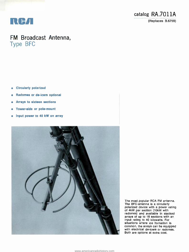
RC/1
FM Broadcast Antenna, Type BEC
Circularly polarized
Radomes or de -icers optional
Arrays to sixteen sections
Tower -side or pole -mount
Input power to 40 kW on array
catalog RA.7011A (Replaces B.6759)
The most popular RCA FM antenna. The BFC- antenna is a circularly polarized device with a power rating of 4kW per section (10kW with radomes) and available in stacked arrays of up to 16 sections with an input rating to 40 kilowatts. For situations where ice formation is common, the arrays can be equipped with electrical de -icers or radomes. Both are options at extra cost.
www.americanradiohistory.com

RA.7011A
Pattern Circularity ±1dB The arrays described here offer radiation
circularity within 1dB in free space. In side -mount situations, tower metal and guy wires affect the circularity to varying de- grees. We recommend that side -mounted arrays be above the highest guy wire. When such is impractical, the guy wires can be insulated from the tower and at 3.5 -foot (1.07m) intervals for a distance of 14 feet (4.4m) from the point where the guy touches the tower.
Pole or Tower -Leg Mount BFC- antenna arrays side -mount on the
corners or faces of towers or on a pole as a' top -mount antenna. Mounting brackets are included for mounting on plumb poles or round tower legs up to 12 inches (305mm) in diameter or tower faces up to 3 feet (914mm) between leg centers. Brackets for self -supporting (tapered) tow- er legs, angle -iron tower legs and poles with diameters larger than 12 inches (305mm) are available at extra cost. Mounting on tower faces wider than 3 feet between leg centers is practical with cer- tain additional materials. Practicality usually recommends leg mounting in such situation.
End -Fed or Center -Fed Arrays Two power distribution methods are
used with the BFC- antenna. In arrays of seven sections and fewer, the array is end -fed (unless the array includes beam tilt and /or null -fill); in eight section and larger arrays, the sections are fed from a center point. The input connection in either case is a 3%s inch diameter, 50 -ohm, EIA- flanged transmission line.
Integral, Effective De-icers The BFC- antenna is available with or
without electrical de- icers. The system uses the resistance of the antenna element itself for de -icing by passing low- voltage, high - current energy through the element. This is a highly effective and reliable de -icing system. The de -icers operate from 208/ 240 -volt a -c power with current trans- formers mounted near the antenna sections on the pole or tower.
Radomes Optional For operating situations where icing
conditions are frequent and /or severe, radomes are made available for BFC - arrays. Using radomes instead of de -icers saves about 18 pounds (8.6kg) of dead- weight per section and increases windload by about 134 pounds (60kg) per section at 50/55 lbs /ft.' (244/161 kg /m') wind pressure. Using radomes increases the max- imum power per section from 4 to 10kW in arrays of four sections and fewer.
Power Gain Proportional to Sections in Array
Each section of a multi- section array provides slightly less than 0.5 power gain in each polarization. This factor improves slightly (see specifications) as the num- ber of sections in the array increases. To illustrate, a 16- section array provides a power gain of 8.9 in each polarization while a one -section array provides 0.46 power gain.
Low VSWR -Field Adjustable VSWR of the BFC- antenna is adjusted
at the factory for a ratio of 1.1:1 over the operating channel. The units are ad- justable in the field and a VSWR of that value or better can be achieved with the antenna in its ultimate environment.
Beam Tilt and Null Fill, Directional Arrays
Beam -tilt and /or Null -Fill is an optional extra on the BFC- series. These options are ordinarily specified for the larger arrays (eight sections and more). However, ar- rays of seven sections and fewer may include one or both options. When such is the case, the array is supplied as a center -fed system (rather than end -fed) at additional expense.
The BFC antenna is available in direc- tional arrays which are custom built to the needs of the directivity situation.
www.americanradiohistory.com

H TOP
1
HC
TOP
Pole Mounting
Mechanical Data
Mounting Dimensions and Feed Line Locations
H SIDE
t SI DE
1
3 % BEIA FLANGE (STAN DARD)
Side Mounting End Feed 1 -7 Sections
fl
PA.701 I A
CENTER
Center Feed 8 -16 Sections
'Can be made to dimension des'ved to bring input line in line with mein vertical run.
Antenna Typo
Frog. MHs
Dimensions in Foot (Motors)1 Windloadl at 50/30 lbs /h2 (244/146 kg /m2)
Hc Top Foot Motors
Hc Sid. Foot Motors
H Top Foot Motors
H Side Foot Meters
Lou Ds -Icons Lbs. Kg.
With De -Icons Lbs. Kg.
With Radome. Lbs. Kg.
88 5.0 1.32 0.8 0.24 8.0 2.44 1.7 0.52 178 81 198 90 332 151 BFC -1 98 5.0 1.52 0.8 0.24 8.0 2.44 1.7 0.52 178 81 198 90 332 151
108 5.0 1.52 0.8 0.24 8.0 2.44 1.7 0.32 178 81 198 90 332 151
88 10.6 3.23 6.4 1.95 19.2 5.85 12.8 3.90 337 153 377 171 645 293 BFC -2 98 10.0 3.05 5.8 1.77 19.0 5.79 11.7 3.57 327 148 367 167 635 288
108 9.5 2.90 5.4 1.65 18.0 5.49 10.8 3.29 319 145 359 163 627 284
88 16.2 4.93 11.9 3.63 30.4 9.27 23.9 7.28 495 225 355 252 957 434 BFC -3 98 15.0 4.57 10.9 3.32 28.9 8.81 21.8 6.64 475 215 535 243 937 425
108 14.1 4.30 9.9 3.02 27.5 8.38 19.9 6.07 459 208 519 235 921 418
88 21.7 6.61 17.6 5.36 41.5 12.65 35.2 10.73 653 296 723 328 1269 576 BFC-4 98 20.0 6.10 15.9 4.85 38.4 11.70 31.8 9.69 623 283 703 319 1239 362
108 18.6 5.67 14.5 4.42 36.8 11.22 29.0 8.84 599 272 679 308 1215 551
88 27.3 8.32 23.2 7.07 52.7 16.06 46.4 14.14 810 367 911 413 1581 717 BFC -5 98 25.0 7.62 20.9 6.37 49.4 15.06 41.8 12.74 791 359 871 395 1541 699
108 23.2 7.07 19.0 5.79 46.1 14.05 38.1 11.61 763 346 839 381 1510 685
88 32.9 10.03 28.8 8.78 63.9 19.48 57.6 17.56 970 440 1090 494 1874 850 BFC-6 98 30.0 9.14 25.4 7.74 59.3 18.07 50.9 15.31 920 417 1040 472 1824 827
108 27.7 8.44 23.6 7.19 54.9 16.73 47.2 14.39 882 400 1000 454 1784 809
88 38.5 11.73 34.3 10.45 75.0 22.86 68.7 20.94 1128 512 1268 575 2183 990 BFC -7 98 35.1 10.70 30.9 9.42 68.7 20.94 61.9 18.87 1068 484 1208 548 2123 963
108 32.3 9.85 28.1 8.56 64.2 19.57 56.3 17.16 1020 463 1160 526 2075 941
88 44.0 13.41 40.0 12.19 86.2 26.27 80.0 24.38 1308 593 1468 666 2514 1140 BFC-8 98 40.1 12.22 33.9 10.94 78.9 24.05 71.9 21.92 1238 562 1398 634 2454 1113
108 36.8 11.22 32.7 9.97 73.2 22.31 65.4 19.93 1182 536 1342 609 2390 1084
88 55.2 16.82 51.1 15.58 108.6 33.22 102.2 33.22 1625 737 1875 851 3165 1436 IFC-10 98 30.1 15.27 46.0 14.02 98.6 30.05 92.0 28.04 1535 696 1735 787 3075 1395
108 45.9 13.99 41.8 12.74 91.2 27.80 83.7 25.51 1483 673 1663 754 3003 1362
88 66.4 20.24 62.3 18.99 131.0 39.93 124.7 38.10 1942 881 2182 990 3790 1719 BFC -12 98 60.1 18.32 56.0 17.07 119.8 36.58 112.1 34.14 1832 831 2072 940 3680 1669
108 55.0 16.76 51.0 15.54 109.6 33:53 101.9 31.09 1744 791 1984 900 3592 1629
88 POLE MOUNT 73.5 22.40 POLE MOUNT 147.0 44.81 2258 1024 2538 1151 4414 2002 BFC -14 98 NOT 66.1 20.15 NOT 132.2 40.23 2128 965 2408 1092 4284 1943
108 RECOMMENDED 60.0 18.29 RECOMMENDED 120.1 36.58 2088 947 2304 1045 4244 1925
88 POLE MOUNT 84.7 25.82 POLE MOUNT 169.4 51.51 2575 1168 2895 1313 5039 2286 BFC -16 98 NOT 76.1 23.20 NOT 152.3 46.33 2425 1100 2745 1245 4889 2218
108 RECOMMENDED 69.1 21.06 RECOMMENDED 138.3 42.06 2205 1000 2625 1191 4669 2118
'Interpolate dimensions and windload for antennas of intermediate frequency.
www.americanradiohistory.com

RA.7011 A
Electrical Data
Antenna Type
Power Gain1 Field
Intensity2
Power Rating3
with Radome. without Radom.. Power dB Field kW dBk kW dBk
BFC -1 0.46 -3.37 0.678 93.2 10 10.0 4 6.02
BFC -2 1.0 0 1.00 137.5 20 13.01 8 9.03
BFC -3 1.5 1.76 1.23 169.1 30 14.77 12 10.79
BFC -4 2.1 3.22 1.45 199.2 40 16.02 16 12.04
BFC -5 2.7 4.31 1.64 225.5 403 16.02 20 13.01
BFC-6 3.2 5.05 1.79 246.1 403 16.02 24 13.80
BFC -7 3.8 5.80 1.95 268.1 403 16.02 28 14.47
BFC -8 4.3 6.34 2.07 284.6 403 16.02 32 15.05
BFC -10 5.5 7.40 2.35 323.1 403 16.02 40 16.02
BFC -12 6.6 8.20 2.57 353.4 403 16.02 40 16.02
BFC -14 7.8 8.92 2.79 383.6 403 16.02 40 16.02
BFC -16 8.9 9.49 2.98 409.8 403 16.02 40 16.02
'Power gain in each polarization. -Effective free -space field intens'ty at 1 mile (1.604 km) 'Power Rating based on a 40° C ambient. Multioly values in mV /m fo 1 kW antenna input power for either equiv-listed by 0.8 for 50° C ambient. BFC -5 and larger an aient horizontally polarized component or equivalent tennas with greater power ratings are available on vertically polarized component. special order.
General Specifications Accessories Polarization Circular Input Adapters: Horiz. Pattern Circularity in Free Space ±1 dB Inner Conductor Adapters to connect:
Vert. Pattern Circularity in Free Space ±1 dB MI- 19113C Line MI -19313 Line
MI- 27988 -4A MI- 27988 -4B
VSWR at Input, Top Mounted, w/o field trim 1.2:1 max. Adapters to connect: VSWR at Input, Side Mounted, w/o field trim 1.5:1 max. Male end of MI- 27791D Line MI- 27791D -7A
VSWR at Input, Top- or Side- Mount, w /field trim (200 kHz) 1.1:1
Female end of MI- 27791D Line Reducers, Quick -Step, to connect:
MI- 27791D -7B
Input Connection Diameter (50 -ohm, EIA Flange) 3W' 1% -inch Flexible Line 7/8 -inch Flexible Line
MI- 27988 -5C MI- 27938 -5D
Input Power Rating (in kilowatts) See Elec. Data Chart Thermostatic De -Icer Control MI- 27369A Section Dimensions 20.7" (526mm) dia.; 20" (508mm) H Rosemount Antenna Ice Detector MI- 561572 Windload See Mech. Data Chart AM /FM Tower Isolator, Type BAF -15/16 MI- 561573/4 Feedpoint Locations (Approx.):
Seven Sections and Fewer (below lowest section) 13' (4m) Ordering Information Eight Sections and More (below array center) 15' (4.6m)
Deadweight in Pounds (kg)1: Single Section Two Sections
With De -Icare
76(34) 137(62)
Less De -Icare
136(62)
257(117)
With Radomen
118(54)
221(100)
Antenna Type No. Sections
Power Gain Per
Polarization Law
DeIcera With
De-icers With
Radoma
Three Sections 198(90) 378(171) 334(152) BFC-1 1 0.46 ES-561921A ES-561921B ES-561921C
Four Sections 259(117) 499(226) 327(194) BFC-2 2 1.00 ES-561922A ES-561922B ES-561922C
Five Sections 320(145) 620(281) 530(240) BFC-3 3 1.50 ES-561923A ES-561923B ES-561923C
Six Sections 381(173) 741(336) 633(287) BEC-4 4 2.10 ES-561924A ES-561924B ES-561924C
Seven Sections 442(200) 862(391) 736(334) BFC-5 5 2.70 ES-561925A ES-561925B ES-561925C
Eight Sections 513(233) 993(450) 849(385) BFC-6 6 3.20 ES-561926A ES-561926B ES-561926C
Ten Sections 635(288) 1235(560) 1055(479) BFC-7 7 3.80 ES-561927A ES-561927B ES-561927C
Twelve Sections 757(343) 1477(670) 1261(572) BFC-8 8 4.30 ES-561928A ES-561928B ES-561928C
Fourteen Sections .._ 879(399) 1719(780) 1467(665) BFC-10 10 5.50 ES-561929A ES-561929B ES-561929C
Sixteen Sections 1001(454) 1961(890) 1673(759) BFC-12 12 6.60 ES-561930A ES-561930B ES-561930C
BFC-14 14 7.80 ES-561931 A ES-561931B ES-561931C 'Weight includes feed system from sections to input connection and 13- to
18 -inch (330 to 457 mm) extension brackets for mounting. BFC-16 16 8.90 ES-561932A ES-5619328 ES-561932C
www.americanradiohistory.com

RCA Tri -Pole FM Broadcast Antenna, Type
Circularly polarized
Adjustable polarization ratio
Integral de -icers optional
Arrays to 16 sections
Pole or tower -leg mount
catalog RA.7111A (Replaces B.6751)
The BFG- Series of antennas are circularly polarized elements with a power rating of 6kW per section and available in stacked arrays of up to 16 sections with an input rating to 40 kilowatts. The BFG- antenna is a three -pole system with factory - adjustable elements that allow control of the ratio between vertical and horizontal polarization. The elements of the antenna section may be adjusted to provide maximum ERP in the horizontal plane and less in the vertical plane. This is most useful where available transmitter power is less than necessary for maximum ERP in both planes.
www.americanradiohistory.com
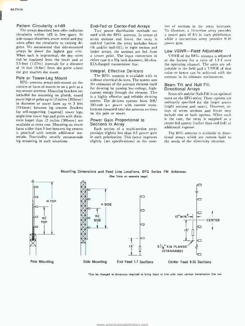
RA.7111 A
Pattern Circularity ±1dB The arrays described here offer radiation
circularity within 1dB in free space. In side -mount situations, tower metal and guy wires affect the circularity to varying de- grees. We recommend that side- mounted arrays be above the highest guy wire. When such is impractical, the guy wires can be insulated from the tower and at 3.5 -foot (1.07m) intervals for a distance of 14 feet (4.4m) from the point where the guy touches the tower.
Pole or Tower -Leg Mount BFG- antenna arrays side -mount on the
corners or faces of towers or on a pole as a top -mount antenna. Mounting brackets are included for mounting on plumb, round tower legs or poles up to 12 inches (305mm) in diameter or tower faces up to 3 feet (914mm) between leg centers. Brackets for self -supporting (tapered) tower legs, angle -iron tower legs and poles with diam- eters larger than 12 inches (305mm) are available at extra cost. Mounting on tower faces wider than 3 feet between leg centers is practical with certain additional ma- terials. Practicality usually recommends leg mounting in such situations.
H TOP
7- HC
TOP
Pole Mounting
End -Fed or Center -Fed Arrays Two power distribution methods are
used with the BFG- antenna. In arrays of seven sections and fewer, the array is end -fed (unless the array includes beam tilt and /or null -fill); in eight section and larger arrays, the sections are fed from a center point. The input connection in either case is a 3/8 inch diameter, 50 -ohm. EIA- flanged transmission line.
Integral, Effective De-icers The BFG- antenna is available with or
without electrical de- icers. The system uses the resistance of the antenna element itself for de -icing by passing low- voltage, high - current energy through the element. This is a highly effective and reliable de -icing system. The de -icers operate from 208/ 240 -volt a -c power with current trans- formers mounted near the antenna sections on the pole or tower.
Power Gain Proportional to Sections in Array
Each section of a multi -section array provides slightly less than 0.5 power gain in each polarization. This factor improves slightly (see specifications) as the num-
ber of sections in the array increases. To illustrate, a 16- section array provides a power gain of 8.9 in each polarization while a one -section array provides 0.46 power gain.
Low VSWR -Field Adjustable VSWR of the BFG- antenna is adjusted
at the factory for a ratio of 1.1:1 over the operating channel. The units are ad- justable in the field and a VSWR of that value or better can be achieved with the antenna in its ultimate environment.
Beam Tilt and Null Fill, Directional Arrays
Beam -tilt and /or Null -Fill is an optional extra on the BFG- series. These options are ordinarily specified for the larger arrays (eight sections and more). However, ar- rays of seven sections and fewer may include one or both options. When such is the case, the array is supplied as a center -fed system (rather than end -fed) at additional expense.
The BFG antenna is available in direc- tional arrays which are custom built to the needs of the directivity situation.
Mounting Dimensions and Feed Line Locations, BFG Series FM Antennas. (See Table on opposite page)
1
H SIDE t HC
SIDE 12" MIN.*
15'
13' 3%8 "EIA FLANGE (STANDARD)
Side Mounting End Feed 1 -7 Sections
CENTER
Center Feed 8 -16 Sections
Can be changed to dimension required to bring input in lire with main vertical transmission line run
www.americanradiohistory.com

Mechanical Data
RA.7111A
Antenna Type
Freq. MHz
Dimensions1 (Sae Drawing) Windload'. at 50/30 Ibs /ft2 (244 /146 kg /m2)
Ne Top Feet Meters
He Side Feat Maters
H Top Feet Meters
H Side Feet Meters
Less De Lbs.
-Icers Kg.
With De-leers Lbs. Kg.
With Radome. Lbs. Kg.
88 5.0 1.52 0.8 0.24 8.0 2.44 1.7 0.52 178 81 198 90
BFG -1 98 5.0 1.52 0.8 0.24 8.0 2.44 1.7 0.52 178 81 198 90 108 5.0 1.52 0.8 0.24 8.0 2.44 1.7 0.52 178 81 198 90
88 10.6 3.23 6.4 1.95 19.2 5.85 12.8 3.90 337 153 377 171
BFG-2 98 10.0 3.05 5.8 1.77 19.0 5.79 11.7 3.57 327 148 367 167 108 9.5 2.90 5.4 1.65 18.0 5.49 10.8 3.29 319 145 359 163
88 16.2 4.93 11.9 3.63 30.4 9.27 23.9 7.28 495 225 555 252
BFG-3 98 15.0 4.57 10.9 3.32 28.9 8.81 21.8 6.64 475 215 535 243
108 14.1 4.30 9.9 3.02 27.5 8.38 19.9 6.07 459 208 519 235
88 21.7 6.61 17.6 5.36 41.5 12.65 35.2 10.73 653 296 723 328 BFG -4 98 20.0 6.10 15.9 4.85 38.4 11.70 31.8 9.69 623 283 703 319 w
108 18.6 5.67 14.5 4.42 36.8 11.22 29.0 8.84 599 272 679 308
88 27.3 8.32 23.2 7.07 52.7 16.06 46.4 14.14 810 367 911 413 J BEG-5 98 25.0 7.62 20.9 6.37 49.4 15.06 41.8 12.74 791 359 871 395 03
108 23.2 7.07 19.0 5.79 46.1 14.05 38.1 11.61 763 346 839 381 Q 88 32.9 10.28 28.8 8.78 63.9 19.48 57.6 17.56 970 440 1090 494 J
BFG-6 98 30.0 9.14 25.4 7.74 59.3 18.07 50.9 15.51 920 417 1040 472 - 108 27.7 8.44 23.6 7.19 54.9 16.73 47.2 14.39 882 400 1000 454 Q 88 38.5 11.73 34.3 10.45 75.0 22.86 68.7 20.94 1128 512 1268 575
BFG -7 98 35.1 10.70 30.9 9.42 68.7 20.94 61.9 18.87 1068 484 1208 548 108 32.3 9.85 28.1 8.56 64.2 19.57 56.3 17.16 1020 463 1160 526 Q 88 44.0 13.41 40.0 12.19 86.2 26.27 80.0 24.38 1308 593 1468 666
BFG -8 98 40.1 12.22 35.9 10.94 78.9 24.05 71.9 21.92 1238 562 1398 634 h 108 36.8 11.22 32.7 9.97 73.2 22.31 69.4 21.15 1182 536 1342 609 0 88 55.2 16.82 51.1 15.58 108.6 33.10 102.2 31.15 1625 737 1875 851
BEG-10 98 50.1 15.27 46.0 14.02 98.6 30.05 92.0 28.04 1535 692 1735 787 108 45.9 13.99 41.8 12.74 91.2 27.80 83.7 25.51 1483 673 1663 754
88 66.4 20.24 62.3 18.99 131.0 39.92 124.7 38.01 1942 881 2182 990 BFG -12 98 60.1 18.32 56.0 17.07 119.8 36.52 112.1 34.17 1832 831 2072 1234
108 55.0 16.76 51.0 15.54 109.6 33.41 101.9 31.06 1744 791 1984 900
88 POLE MOUNT 73.5 22.40 POLE MOUNT 147.0 44.81 2258 1024 2538 1151 BFG -14 98 NOT 66.1 20.15 NOT 132.2 40.29 2128 965 2408 1092
108 RECOMMENDED 60.0 18.29 RECOMMENDED 120.1 36.61 2088 947 2304 1045
88 POLE MOUNT 84.7 25.82 POLE MOUNT 169.4 51.63 2575 1168 2895 1313 BEG -16 98 NOT 76.1 23.20 NOT 152.3 46.42 2425 1100 2745 1245
108 RECOMMENDED 69.1 21.06 RECOMMENDED 138.3 42.15 2205 1000 2625 1191
1 Interpolate dimensions and windload for antennas of intermediate frequency.
www.americanradiohistory.com

RA.7111A
General Specifications Polarization Circular Horiz. Pattern Circularity in Free Space ±1dB Vert. Pattern Circularity in Free Space ±1dB VSWR at Input, Top Mounted, w/o field trim 1.2:1 max. VSWR at Input, Side Mounted, w/o field trim 1.5:1 max. VSWR at Input, Top- or Side -Mount,
w /field trim (200 kHz) 1.1:1
Input Connection Diameter (50 -ohm, EIA Flange) 31/8"
Input Power Rating See Elec. Data Chart Section Dimensions 25" (635mm) dia.; 20" (508mm) H
Windload See Mech. Data Chart Feedpoint Locations (Approx.):
Seven Sections and Fewer (below lowest section) 13' (4m) Eight Sections and More (below array center) 15' (4.6m)
Weight in Pounds (kg):' Less De -Icers
With De -Icers
Single Section 76(34) 136(62) Two Sections 137(62) 257(117) Three Sections 198(90) 378(171) Four Sections 259(117) 499(226) Five Sections 320(145) 620(281) Six Sections 381(173) 741(336) Seven Sections 442(200) 862(391) Eight Sections 513(233) 993(450) Ten Sections 635(288) 1235(560) Twelve Sections 757(343) 1477(670) Fourteen Sections 879(399) 1719(780) Sixteen Sections 1001(454) 1961(890)
'Weight includes feed system to antenna input and 13- to 18 -inch (330 to 457mm) extension brackets for mounting.
Accessories Input Adapters:
Inner Conductor Adapter to connect: MI- 191130 Line MI- 27988 -4A MI -19313 Line MI- 27988 -46
Adapter to connect: Male end of MI- 27791D Line MI- 27791D -7A Female end of MI- 27791D Line MI- 27791D -7B
Reducers, Quick -Step, to connect: 1% -inch Flexible Line MI- 27988 -5C 7/s -inch Flexible Line MI- 27988 -5D
Thermostatic De -icer Control MI- 27369A
Rosemount Antenna Ice Detector MI- 561572
AM /FM Tower Isolator, Type BAF -15/16 MI- 561573/4
Electrical Data Type BFG-
Antenna Type
Power Gainl Field
Intensity
Power Rating=
Power dB Field kW dBk
BFG -1 0.9 -0.45 0.95 130.6 6 7.78
BFG -2 2.0 3.01 1.41 193.9 12 10.79
BFG-3 3.0 4.77 1.73 237.9 18 12.55
BFG -4 4.2 6.23 2.05 281.9 24 13.80
BF0-5 5.4 7.32 2.32 319.0 30 14.77
BFG-6 6.4 5.06 2.53 347.9 36 15.56
BFG-7 7.6 8.80 2.76 379.5 402 16.02
BFG.8 8.6 9.34 2.93 402.9 402 16.02
BEG-10 11.0 10.41 3.32 456.5 402 16.02
BFG-12 13.2 11.20 3.63 499.1 402 16.02
BFG-14 15.6 11.93 3.95 543.1 402 16.02
BFG-16 17.8 12.50 4.22 580.3 402 16.02
'Horizontal and vertical gain combined. Horizontally polarized gain may be
specified at any level between 50 and 90 percent of total gain listed. Vertical power gain ,s then equal to the combined gain less the horizontal gain. For
each polarization, the field gain is equal to the square root of the power gain. The effective field intensity at one mile (1.604 km) for 1 kW input is
equal to 137.5 times the field gain. Power Rating based on a 40° C ambient. Multiply values listed by 0.8 for 50° C ambient. BFG -7 and larger antennas with greater power ratings are
available on special order.
Ordering Information Type BFG-
Antenna Type No. Sections
Power Gain* Her. Plus Vert.
Less Da-Icers
With De-icers
BEG-1 1 0.9 ES-561951A ES-561951B BFG-2 2 2.0 ES-561952A ES-561952B BFG-3 3 3.0 ES-561953A ES-561953B BFG-4 4 4.2 ES-561954A ES-561954B BFG-S 5 5.4 ES-561955A ES-5619558 BF0. 6 6.4 ES-561956A ES-5619568 BFG-7 7 7.6 ES-561957A ES-561957B BFG-8 8 8.6 ES-561958A ES-561958B BFG-10 10 11.0 ES-561959A ES-5619598 BFG-12 12 13.2 ES-561960A ES-5619608 BFG-14 14 15.6 ES-561961A ES-5619618 BFG-16 16 17.8 ES-561962A ES-5619628
Power gain in horizontal polarization may be specified at any point between 50 and 75 percent of tote gain shown.
www.americanradiohistory.com

RCA Economy FM Broadcast Antennas, Type bf -H- Series
Circularly polarized
Integral de -icers optional
Arrays to eight sections
For Class A stations
Input power to 8 kW on array
catalog RA.7211A (Replaces B.6753)
The BFI-l- antenna series is intended for the Class A FM station seeking performance on a budget. The BFti- antenna is a low -power version of the BFC- and is available in one through eight sections with a power - input rating to 8kW. The BFH- antenna provides BFC- antenna performance to the Class A FM station at purchase prices significantly lower than those of the high -power antenna.
www.americanradiohistory.com

A.7211 A
Pattern Circularity -:1dB The arrays described here offer radiation
circularity within 1dB in free space. In side -mount situations, tower metal and guy wires affect the circularity to varying de- grees. We recommend that side -mounted arrays be above the highest guy wire. When such is impractical, the guy wires can be insulated from the tower and at 3.5 -foot (1.07m) intervals for a distance of 14 feet (4.4m) from the point where the guy touches the tower.
Pole or Tower -Leg Mount BFH- antenna arrays side -mount on the
corners or faces of towers or on a pole as a top -mount antenna. Mounting brackets are included for mounting on plumb, round towcr legs or poles up to 12 inches (305mm) in diameter or tower faces up to 3 feet (914mm) between leg centers. Brackets for self -supporting (tapered) tow- er legs, angle -iron tower legs and poles with diameters larger than 12 inches (305mm) are available at extra cost. Mounting on
tower faces wider than 3 feet between leg centers is practical with certain additional materials. Practicality usually recommends leg mounting in such situations.
End -Fed or Center -Fed Arrays Two power distribution methods are
used with the BFH- antenna. The array is
usually end -fed unless it includes beam tilt and /or null -fill. In this case, the sec- tions arc fed from a center point. The input connection in either case is a 1% inch diameter, 50 -ohm, EIA- flanged trans- mission line.
Integral, Effective De-icers The BFH- antenna is available with or
without electrical de- icers. The system uses the resistance of the antenna element itself for de -icing by passing low- voltage, high - current energy through the element. This is a highly effective and reliable de -icing system. The de -icers operate from 208/ 240 -volt a -c power with current trans-
formers mounted near the antenna sections on the pole or touer.
Power Gain Proportional to Sections in Array
Each section of a multi -section array provides slightly less than 0.5 power gain in each polarization. This factor improves slightly (see specifications) as the num- ber of sections in the array incresases. To illustrate, an 8- section array provides a power gain of 4.3 in each polarization while a one -section array provides 0.46 power gain.
Beam Tilt and Null Fill, Directional Arrays
Beam -tilt and /or Null -Fill is an optional extra on the BFH- series. These options arc ordinarily specified for the larger arrays (eight sections). However, arrays of seven sections and fewer may include one or both options. When such is the case, the array is supplied as a center -fed system (rather than end -fed) at additional ex- pense.
www.americanradiohistory.com

rA.7211A
Mounting Dimensions and Feed Line Locations, BFH Series FM Antennas.
H TOP
He TOP
- -L
Pole Mounting
HC
SIDE
1
H SIDE
6'
Side Mounting End Feed
Mechanical Data
Antenna Type
Freq. MHz
Dimensional (See Drawing) Windloadl at
50/30 lbs /ft' (244 /146/kg')
He Top Feet Meters
He Side Feet Meters
H Top Feet Meters
H Side Feet Meters
Less De -icers Lbs. Kg.
With De-icers Lbs. Kg.
88 5.0 1.52 0.8 0.24 8.0 2.44 1.7 0.52 116 53 139 63
BFH -1 98 5.0 1.52 0.8 0.24 8.0 2.44 1.7 0.52 116 53 139 63
108 5.0 1.52 0.8 0.24 8.0 2.44 1.7 0.52 116 53 139 63
88 10.6 3.23 6.4 1.95 19.2 5.85 12.8 3.90 220 100 264 120
BFH -2 98 10.0 3.05 5.8 1.77 19.0 5.79 11.7 3.57 213 97 257 117
108 9.5 2.90 5.4 1.65 18.0 5.49 10.8 3.29 208 94 252 114
88 16.2 4.93 11.9 3.63 30.4 9.27 23.9 7.28 322 146 389 176
BFH-3 98 15.0 4.57 10.9 3.32 28.9 8.81 21.8 6.64 309 140 375 170
108 14.1 4.30 9.9 3.02 27.5 8.38 19.9 6.07 299 136 364 165
88 21.7 6.61 17.6 5.36 41.5 12.65 35.2 10.73 425 193 507 259 BFH-4 98 20.0 6.10 15.9 4.85 38.4 11.70 31.8 9.69 405 184 493 224
108 18.6 5.67 14.5 4.42 36.8 11.22 29.0 8.84 390 177 476 216
88 27.3 8.32 23.2 7.07 52.7 16.06 46.4 14.14 527 239 638 289
BFH -5 98 25.0 7.62 20.9 6.37 49.4 15.06 41.8 12.74 515 234 610 277 108 23.2 7.07 19.0 5.79 46.1 14.05 37.1 11.61 496 225 588 267
88 32.9 10.28 28.8 8.78 63.9 19.48 57.6 17.50 631 286 763 346
BFH-6 98 30.0 9.14 25.4 7.74 59.3 18.07 50.9 15.51 599 272 728 330 108 27.7 8.44 23.6 7.19 54.9 16.73 47.2 14.39 574 260 700 318
88 38.5 11.73 34.3 10.45 75.0 22.86 68.7 20.94 734 333 888 403
BFH -7 98 35.1 10.70 30.9 9.42 68.7 20.94 61.9 18.87 695, 315 846 384 108 32.3 9.85 28.1 8.56 64.2 19.57 56.3 17.16 663 301 812 368
88 44.0 13.41 40.0 12.19 86.2 26.27 80.0 24.38 851 386 1028 466 BFH -8 98 40.1 12.22 35.9 10.94 78.9 24.05 71.9 21.92 805 365 979 445
108 36.8 11.22 32.7 9.97 73.2 22.31 65.4 21.15 769 349 940 426
1 Interpolate dimensions and windload for antennas of intermediate frequencies.
www.americanradiohistory.com

RA.7211A
General Specifications Polarization Circular Horiz. Pattern Circularity in Free Space ±1dB Vert. Pattern Circularity in Free Space ± ±1dB VSWR at Input (Adjusted at factory) 1.1:1*
Input Connection Diameter (50 -ohm, EIA Flange) 15A"
Input Power Rating (in kilowatts) See Elec. Data Chart Section Dimensions . 17" (432mm) dia.; 15" (381mm) H
Wind load _ _ _ ..__...... See Mech. Data Chart Feedpoint Locations (Approx.):
Eight Sections and Fewer (below lowest section) 6' (1.8m)
Weight (Approx): With De -icers Less De -icers Single Section _ _ 82 lbs(37kg)1 30 lbs (14kg)1
Two Sections 154 lbs (70kg)1 51 lbs (23kg)' Three Sections _ . 226 lbs (103kg)1 79 lbs (36kg)1 Four Sections . 300 lbs (136kg)1 104 lbs (47kg)1 Five Sections 372 lbs (169kg)1 128 lbs (58kg)1
Six Sections _ 446 lbs (202kg)1 153 lbs (69kg)1 Seven Sections 520 lbs (236kg)1 177 lbs (80kg)1 Eight Sections 595 lbs (270kg)1 205 lbs (93kg)1
'Weight includes elements, feed system to antenna input and 13- to 18 -inch (330- to 457mm) extension brackets for mounting.
Accessories Reducer, Quick -Step, to connect
7/8 -inch flexible line _....
Thermostatic De-icer Control Rosemount Antenna Ice Detector AM /FM Tower Isolator, Type BAF -15/16
M I.27988-5E
MI-27369A
MI-561572
MI-561573/4
Electrical Data Type BFH-
Antenna Type
Power Gainl Field
Intensity " --
Power Rating
Power dB Field kW dik
8FH -1 0.46 -3.37 0.678 93.2 2 3.01
BFH -2 1.0 0 1.00 137.5 4 6.02
BFH-3 1.5 1.76 1.23 168.4 6 7.78
BFH-4 2.1 3.22 1.45 199.2 8 9.03
BFH -5 2.7 4.31 1.64 223.2 8 9.03
BFH-6 3.2 5.05 1.79 246.0 8 9.03
8FH -7 3.8 5.80 1.95 268.0 8 9.03
BFH8 4.3 6.34 2.07 285.2 8 9.03
'Power gain in each polarization. 'Effective free -space field intensity at 1 mile (1.604 km) at 1 kW antenna
input power for either equivalent horizontally polarized component or equivalent vertically polarized component.
Ordering Information Type BFH- Antenna
Type No. Sections Power Gain
Per Polarization Less
De -leers With
De -Icers
BFH -1 1 0.46 ES-561941A ES-5619418
BFH -2 2 1.00 ES-561942A ES-561942B
'BFH -3 3 1.50 ES-561943A ES-5619438
BrH -4 4 2.10 ES-561944A ES-561944B
,BFH -5 5 2.70 ES-561945A ES-5619458
BFH -6 6 3.20 ES-561946A ES-561946B
1BFH -7 7 3.80 ES-561947A ES-561947B
IBFH -8 8 4.30 I ES-561948A ES-5619488
Brackets included for mounting to vertical (plumb) poles, round tower legs or vertical tower face with less than 3 feet (914 mm) between leg centers. Please specify antenna mount (corner, face, pole) and dimensions of structure near antenna (for bracket dimensions).
www.americanradiohistory.com

Educational FM Antenna, Type BFI- Series
Circular or horizontal polarization
Low cost, 10 -watt power input
Arrays of one or two sections
Low windload
Low cost cable feedline
catalog RA.7311A (Replaces B.6755)
The BFI- antenna series are low -power elements for the 10 -watt educational /campus FM station. It is available in circular or horizontal polarization in one- or two -section arrays. Mounting brackets are not included. Connector is Type "N ". Specifications and ordering information in next page.
www.americanradiohistory.com

RA.7311 A
1
H TOP
HC
TOP
1
Pole Mounting
H SIDE
Side Mounting
General Specifications Type BFI -C Type BFI -H
Polarization Circular Horizontal Horiz. Pattern Circularity
in Free Space ±1dB ±1dB Vert. Pattern Circularity
in Free Space ±1dB ±1dB VSWR (Factory adjusted)* 1.1:1 1.1:1
Input Connection Type N Type N
Input Power Rating (in kilowatts) See Elec. Data Chart
Section Dimensions Diameter 17" (432mm) 17" (432mm) Height (max.) 15" (381mm) 15" (381mm)
Windload See Mech. Data Chart Deadweight:
Single Section 18 lbs. (10kg) 18 lbs. (10kg) Two Sections 36 lbs. (16kg) 36 lbs. (16kg)
When mounted on tower, the VSWR may be greater than 1.1:1 due to coupling effects.
Mechanical Data
Antenna Type
Freq. MHz
Dimensions (See Drawing)
Windload at 50/30 lbs /Ft' (244/146/kg')
He Side Feet Me
H Side Feat Me
Less De -Icers Lbs. Kg.
88 0.8 0.24 1.7 0.52 50 23 BFI -1C 98 0.8 0.24 1.7 0.52 50 23
108 0.8 0.24 1.7 0.52 50 23
88 6.4 1.95 12.8 3.90 109 49 BFI.2C 98 5.8 1.77 11.7 3.57 109 49
108 5.4 1.65 10.8 3.29 109 49
88 0.8 0.24 1.7 0.52 46 21
BFI.1H 98 0.8 0.24 1.7 0.52 46 21
108 0.8 0.24 1.7 0.52 46 21
88 6.4 1.95 12.8 3.90 105 48 BFI-2H 98 5.8 1.77 11.7 3.57 105 48
108 5.4 1.65 10.8 3.29 105 48
Electrical Data
Antenna Typs
Power Gain Field
Intensity'
Power Rating
Power dB Field kW dBk
BFI -1C 0.46 -3.37 0.68 93.2 0.5 -3 BFI -2C 1.00 0 1.00 137.5 0.5 -3 BFI -1H 0.90 -0.45 0.95 130.0 0.5 -3 BFI -2H 1.90 3.01 1.41 194.0 0.5 -3
'Effective free -space field intensity at 1 mile (1.604 km) at 1 kW antenna input power for either equivalent horizontally polarized component or equiv aient vertically polarized comoonent.
Ordering Information
Antenna Type No.
Sections Power Gain Horiz. Vert.
Catalog Number
BFI-1C 1 0.46 0.46 ES- 561933
BFI -2C 2 1.00 1.00 ES- 561934
BFI.1H 1 0.90 - ES- 561935
BFI -2H 2 1.90 - ES- 561936
Mounting brackets not Included.
www.americanradiohistory.com

Horizontally Polarized FM Antenna, Type r\ -cries
Stainless -steel radiators
Low weight and windload
Side- or top -tower mount
Dual -heat de -icer system
Power gains to 12 dB
catalog RA.7511A (Replaces B.6756)
BFA- antennas are horizontally polarized units for pole -or tower - mount. They are available in arrays of up to 16 sections, with or without de -icers and with or without beam -tilt and /or null -fill.
www.americanradiohistory.com

RA.75114
Pattern Circularity ±1 dB BFA- Series antennas offer radiation cir-
cularity within ±1 dB in free space. In side -mount situations, tower metal and guy wires offset the circularity to varying degrees. We recommend that side -mounted arrays be above the highest guy wire for greatest pattern circularity. As an alterna- tive, when such isn't possible, the guy wires can be insulated from the tower and at 3%2 foot (1.07 m) intervals for a dis- tance of 14 feet (4.4 m) from the point where the guy touches the tower.
Pole- or Tower -Leg Mount All BFA- Series antennas side mount on
the corners or faces of antenna towers or on a pole as a top -mount antenna. All include mounting brackets for plumb, round tower legs up to 12 inches (305 mm) in diameter or tower faces up to 3 feet (914 mm) wide between leg centers. Brackets for mounting on self -supporting (tapered) towers, angle -iron tower legs and poles with diameters larger than 12 inches (305 mm) are available at extra cost. Mounting on tower faces with more than 3 feet (914 mm) between leg centers is possible with certain extra materials. Practicality usually recommends leg mounting in such situations.
End -Fed and Center -Fed Arrays Two power- distribution schemes are
used in the BFA- antenna series. In arrays with eight sections and fewer, the array is end -fed; in eight- section and larger arrays, the sections are fed from a center point. The input connection is a 31/4-inch diameter, 50 -ohm, transmission -line with an EIA flange.
Dual -Heat De-icers All BFA- antenna arrays are available
with or without electrical de- icers. These are dual -heat systems which operate from 208/240 -volt power.
Power Gain Proportional To Sections
Each section of a multi- section array provides approximately unity power gain. This number improves slightly as the number of sections in the array increases. To illustrate, a 16- section BFA- array provides a power gain of 16.5 times while a one -section array provides 0.9 power gain.
Input Connections -Low VSWR BFA- Series antennas use a 3%8 -inch
diameter, 50-ohm transmission line with an EIA flange for an input connection. A VSWR of 1.1:1 installed may be achieved with field adjustment of the in- put transformer.
Electrical Data:
Antenna Type
BFA-1B
BFA-2B
BFA-3B
BFA-4B
BFA-5B
BFA-6B
BFA-7B
BFA-8B
BFA-10B
BFA-12B
BFA-14B
BFA-16B
Power Gain Power Rating
w/o Radome. w /Radoma
kW dBk Power dB kW dBk
0.9 -0.50 5 7.00
1.9 2.80 10 10.00
3.0 4.80 15 11.70
4.0 6.00 20 13.01
5.1 7.10 25 13.98
6.3 8.00 30 14.77
7.3 8.60 35 15.44
8.4 9.20 40 16.02
10.5 10.20 50 16.99
12.5 11.00 60 17.78
14.5 11.62 80 19.03
16.5 12.18 80 19.03
Beam -Tilt and Null -Fill; Directional Arrays
Beam -tilt and /or null -fill is an optional extra on the arrays with 12, 14 or 16 sections. For example the BFA -12, -14 and
16 arrays can include beam -tilt and /or null -fill.
Directional arrays with BFA antennas are available, custom -built to the needs of the coverage situation.
www.americanradiohistory.com

RA .7 511 A
H TOP
I
HC
TOP
Pole Mounting
,
H SIDE
Side Mounting
13'
12 °MIN*
15'
3!' 8
EIA FLANGE' (STAN DARD)
o f
CENTER
b End Feed 1 -7 Sections Center Feed 8 -16 Sections
Drawing for Mechanical Data Chart (below).
Mechanical Data (See drawing above):
Antenna Type
Freq. MHz Hc Top
Feet Meters
Dimensions in Feet (Meters)
Hc Side H Top Feet Meters Feet Meters
H Side Feet Meters
Windload
Less
lbs
at 50/33 lbs /ft (244/146 kg /m') De-icers With De -Icen With Radomes
kg lbs kg lbs kg
88 5.0 1.52 0.50 0.15 8.0 2.44 1.0 0.30 58 26.3 70 31.8 BFA-1B 98 5.0 1.52 0.50 0.15 8.0 2.44 1.0 0.30 58 26.3 70 31.8
108 5.0 1.52 0.5 0.15 8.0 2.44 1.0 0.30 58 26.3 70 31.8
88 10.0 3.05 5.55 1.69 18.1 5.52 11.1 3.38 221 100.2 267 121 BFA-2B 98 9.5 2.90 5.00 1.69 17.0 5.18 10.0 3.05 212 96.1 256 116
108 9.1 2.77 4.60 1.40 16.2 4.94 9.2 2.80 206 93.4 248 112
88 15.1 4.60 10.55 3.22 28.1 8.56 21.1 6.43 319 144.7 385 175 BFA-38 98 14.0 4.27 9.55 2.91 26.1 7.96 19.1 5.82 303 137.4 365 166
108 13.2 4.02 8.70 2.65 24.4 7.44 17.4 5.30 289 131.1 348 158
88 20.1 6.12 15.60 4.75 38.2 11.64 31.2 9.51 416 188.7 502 278 BFA-4B 98 18.6 5.67 14.05 4.28 35.1 10.70 28.1 8.56 391 177.4 471 214
108 17.3 5.27 12.80 3.90 32.6 9.94 25.6 7.80 371 168.3 446 202
88 25.2 7.68 20.65 6.29 48.3 14.72 41.3 12.58 514 233.2 620 281 BFA-5B 98 23.1 7.04 18.60 5.67 44.2 13.47 37.2 11.34 481 218.2 579 263
108 21.4 6.52 16.90 5.15 40.8 12.43 33.8 10.30 454 205.9 545 247
88 31.6 9.63 27.10 8.26 61.2 18.65 54.2 16.52 635 288.0 767 348 BFA-6B 98 28.9 8.80 24.40 7.44 55.8 17.01 48.8 14.87 591 268.0 713 323 a
108 26.7 8.14 22.20 6.77 51.4 15.67 44.4 13.53 556 252.2 669 303 á
88 36.8 11.22 32.35 9.86 71.7 21.85 64.7 19.72 736 333.8 889 >
403 BFA-7B 98
108 33.6 31.0
10.24 9.45
29.15 26.50
8.88 8.08
65.3 60.0
19.90 18.29
58.3 53.0
17.76 16.15
684 642
310.3 825 291.2 772
374 Ó
350 Z 88 42.2 12.86 37.70 11.49 82.4 25.12 75.4 22.98 839 380.6 1014 460
BFA-8B 98 38.4 11.70 33.90 10.33 74.8 22.80 67.8 20.66 778 352.9 938 425 108 35.3 10.76 30.80 9.39 68.6 20.90 61.6 18.78 729 330.6 876 397
88 52.7 16.06 48.25 14.70 103.5 31.54 96.5 29.41 1431 649 1649 748 BFA-10B 98 47.9 14.60 43.45 13.24 93.9 28.62 86.9 26.49 1318 598 1516 688
108 44.0 13.41 39.50 12.04 86.0 26.24 79.0 24.08 1225 556 1407 638
88 63.4 19.32 58.90 17.95 124.8 38.04 117.8 35.91 1712 777 1972 894 BFA-12B 98 57.5 17.53 53.00 16.15 113.0 34.44 106.0 32.31 1591 722 1817 824
108 52.6 16.03 48.10 14.66 103.2 31.46 96.2 29.32 1464 664 1681 763
88 74.1 22.59 69.55 21.20 146.1 44.53 139.1 42.40 1993 904 2295 1041 BFA-14B 98 67.1 20.45 62.55 19.07 132.1 40.26 125.1 38.13 1844 836 2118 961
108 61.2 18.65 56.70 17.28 120.4 36.70 113.4 34.56 1703 772 1955 887
88 84.8 25.85 80.20 24.44 167.4 51.02 160.4 48.89 2273 1031 2607 1183 BFA-16B 98 76.7 23.38 72.10 21.98 151.2 46.09 144.2 43.95 2106 955 2418 1097
108 69.8 21.28 65.30 19.90 137.6 41.94 130.6 ¡ 39.81 1941 880 2228 1011
www.americanradiohistory.com
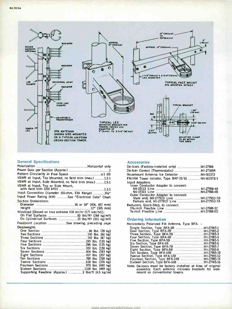
RA.7511A
/Ia(11
DEICER HARNESS OPTIONAL
LEG CLAMPS
RADIATOR
RADIATOR
UNIVERSAL JOINT / RADIATOR
TOWER LEG - BFA ANTENNA
SHOWN SIDE MOUNTED ¡i ON A TYPICAL UNIFORM
I. t CROSS- SECTION TOWER.
FEED LINE CLAMPS
ADJUSTABLE TRANSFORMER
APPROX. I21305mm)
Is'(3BOmm) TO 36'(914 mm)
I APPROX. 12`(lOSmm)
%,\
TYPICAL LEG MOUNTING BRACKET FOR TOWERS HAVING LEG DIAMETER OF 2" 151mm) TO 3-3/4'195 mm)
I- I/ 2`(3B+HI + 2 -3/4" ITO mm) LEG DIAMETER
BAY
TYPICAL FACE MOUNT BFA MOUNTING DETAILS
TYPICAL BRACKET
1.36" (35 mm)
3.25' (63 mm)
2.50" (64 mm)
MOUNTING CLAMP TO BE WITHIN THIS AREA
General Specifications Polarization Horizontal only Power Gain per Section (Approx.) 1
Pattern Circularity in Free Space ±1 dB VSWR at Input, Top Mounted, no field trim (max.) 1.2:1 VSWR at Input, Side Mounted, no field trim (max.) 1.5:1 VSWR at Input, Top or Side Mount,
with field trim (200 kHz) 1.1:1 Input Connection Diameter (50-ohm, EIA flange) 31/B" Input Power Rating (kW)
Section Dimensions: Diameter Height
See "Electrical Data" Chart
16 or 18" (406, 457 mm) 12" (305 mm)
Windload [Based on true extreme 110 mi /hr (177 km /hr)]: On Flat Surfaces 50 lbs/ft2 (244 kg /m2) On Cylindrical Surfaces 33 Ibslft2 (161 kg/m2)
Feedpoint Location See drawing, preceding page Deadweight:
One Section 86 lbs. (39 kg) Two Sections 140 lbs. (64 kg) Three Sections 192 lbs. (87 kg) Four Sections 245 lbs. (111 kg) Five Sections 298 lbs. (135 kg) Six Sections 351 lbs. (159 kg) Seven Sections _ 404 lbs. (183 kg) Eight Sections 457 lbs. (207 kg) Ten Sections 700 lbs. (318 kg) Twelve Sections 830 lbs. (376 kg) Fourteen Sections 970 lbs. (440 kg) Sixteen Sections 1100 lbs. (499 kg) Supporting Feedline (Approx.) 3 lbs /ft (4.5 kg/m)
Accessories De-icers (Factory- Installed only) MI -27986 De -icer Control (Thermostatic) MI- 27369A Rosemount Antenna Ice Detector MI- 561572 FM /AM Tower Isolator, Type BAF -15/16 MI- 561573/4 Input Adapters:
Inner Conductor Adapter to connect: MI -19113 Line MI- 27988 -4A MI -19313 Line MI- 27988 -4B
Outer Conductor Adapter to connect: Male end, MI- 27791D Line MI- 27791D -7B Female end, MI- 27791D Line MI- 27791D -7A
Reducers, Quick -Step, to connect: 1% -inch Flexible Line MI- 27988 -5C 7/e-inch Flexible Line MI- 27988 -5D
Ordering Information Horizontally Polarized FM Antenna, Type BFA- :
Single Section, Type BFA -1B MI- 27985 -1 Dual Section, Type BFA -2B MI- 27985 -2 Three Section, Type BFA -3B MI- 27985 -3 Four Section, Type BFA -4B MI- 27985 -4 Five Section, Type BFA -5B MI- 27985 -5 Six Section, Type BFA -6B MI- 27985 -6 Seven Section, Type BFA -7B MI- 27985 -7 Eight Section, Type BFA -8B MI- 27985 -8 Ten Section, Type BFA -10B MI- 27985 -10 Twelve Section, Type BFA -12B MI- 27985 -12 Fourteen Section, Type BFA -14B MI- 27985 -14 Sixteen Section, Type BFA -16B MI- 27985 -16
Note: De -icers must be factory installed at time of original assembly. Each antenna includes brackets for side - mount on conventional towers.
www.americanradiohistory.com

Ren Multi- Station FM Panel Antennas, Types BFB, BFD, BFE, RFF
Circularly polarized
Directional or omnidirectional patterns
High power capability
Radomed elements
catalog RA.7611A PRELIMINARY
FM Panel Antennas, Types BFB, BFD, BFE and BFF are broadband, custom - tailored antenna systems that permit a number of high powered FM stations to share a common antenna. They are circularly polarized for optimum coverage and perform excellently in either omni- directional or directional applications. Bandwidths range from 4.5 to 20 MHz in the FM broadcast band, and power ratings extend up to 80 kilowatts (CW) per panel.
Flexible Directivity In omnidirectional use, three (or four)
panels are mounted around a tower to make up an antenna layer, and as many layers as necessary are used to obtain the desired power gain. Power gain is equal to approximately one -half the number of antenna layers. Directional radiation is
the result of asymmetrical location of panels and power distribution to the panels.
Fed in Phase Quadrature Each panel consists of a pair of crossed
dipoles with a reflecting screen. The two dipoles are fed in phase quadrature with separate transmission lines from a hybrid coupler. Each panel carries one -half the power of all the stations sharing the system.
A multi- station FM panel antenna sys- tem serving five stations is shown in the block diagram. Four or fewer stations are accommodated by use of T combiners to feed the A and B ports of the hybrid coupler. Ports C and D each contain half the total power of each station in phase quadrature. More than four stations are combined with notch diplexers as illus- trated. In this case, the broadband input port of the last notch diplexer may be used in an emergency to take the output of either station #1 or #2 should the T combiner fail.
High Power Capability Depending upon transmission line limi-
tations, the power rating of a complete FM panel antenna is equal to the power
www.americanradiohistory.com

rating per panel times the number of panels. For example, assume a 12 -layer antenna (gain = approximately 6) with three panels per layer and a rating of 80 kW per panel. The rating of this antenna is:
80 x 12 x 3 = 2880 kW
Since the vector sum of the output voltages is greater for several transmitters as compared to those of a single transmit- ter of equivalent power, the antenna then becomes voltage rather than power lim- ited. The equivalent power of a number of stations feeding the common is ex- pressed as:
P = (VT's + V`2 + \/ 3 )2
or, when all stations have equal power: P = n2P where n is the number of stations and P is the power per station.
The equivalent power of twelve 20 -kW stations would be:
122 x 20 = 2880 kW. Therefore, a 12 -layer antenna can handle twelve 20 -kW stations, and, with a gain of 6, provides an ERP of 100 kW per station.
Ordering Information Types BFB, BFD, BFE and BFF FM Panel
Antennas are sold only as part of a custom built array because of the in- dividuality of each multi -channel arrangement. Your RCA Regional Repre- sentative stands ready to help plan and execute a multi- station FM antenna.
S-
TO ANTENNA
DIPOLE
n
U
STATION I
NOTCH nl EXER
STATION 4
y NOTCH DIPLEXER
STATION 5
NOTCH DIPLEXER
EMERGENCY PORT
n
STATION 2
Typical five -station shared -antenna scheme for FM- broadcast stations using Type BFB -, BFD -, BFE- or BFF- Panel Antennas.
www.americanradiohistory.com

RC/1
RF Load and Wattmeter Systems for FM
Combined dummy antenna and wattmeter
Compact -easily installed
Direct -reading wattmeters
Choice of six power ratings
Air- or water- cooled
catalog RA.7711A
The loads and wattmeters described here are dual -purpose units. As non -inductive dummy loads, they aid in transmitter tune -up without radia- tion; as wattmeters, they terminate the transmitter output and indicate an accurate measure of power output. The resistive elements in loads of one kilowatt and lower radiate the heat energy directly to the surrounding air. The larger loads use resistive elements immersed in a liquid coolant which transfers resistor heat to a heat exchanger. The loads with 10kW and greater capacity use a closed system of water as the coolant. When these loads are subject to freezing temperatures, a solution of 35 percent ethylene glycol and water is used instead of water alone.
www.americanradiohistory.com

RA.7711 A
This is the 20 kW system (Bird 8644/4805/ 25KB3/5 -726) and is representative of the 10- and 40-kW loads as well. The 10-kW load is smaller while the 40- is larger. These loads require a source of commercial power for a coolant pump within the enclosure. An interlock connection, properly used, pre- vents application of power without coolant circulation. Dolly shown is optional as an extra -cost accessory.
10W System
1000W System
3/5 kW System
10 kW System
20 kW System
40 kW System
Input Impedance, Ohms 50 50 50 50 50 50
Input Connection Type N Female (MI- 561565) (MI-27791K) (M I- 27791K) (MI-27791K) (M I- 27791K) 1s/e" aya" aye" 31/2" aye"
Coolant Convection Convection Air (Fan) Water' Water' Water' Ambient Temp. Range ( °C) -40 to +45 -40 to +45 -40 to +45 5 to 452 5 to 452 5 to 452
Power Requirements: Voltage None None 115V 115V3 115V3 115V3
Frequency None None 50/60 Hz 60 Hz4 60 Hz+ 60 Hz+
Current None None 0.44A 9A 9A 25A
Dimensions (Approx.): Height, Inches (mm) 6.15" (171) 11" (279) 15.6" (396) 16" (406) 193" (495) 22" (558) Width, Inches (mm) 8" (203) 7" (177) 7.8" (198) 16" (406) 19" (483) 20" (508) Depth, Inches (mm) 3.5" (89) 36" (914) 32" (813) 25" (635) 28" (711) 54" (1371)
Weight, Lbs. (kg) Approx. 3.75 (1.7) 43 (20) 62 (28) 110 (50) 155 (70) 275 (124)
'Self-contained, no external connections required. 'Range extends to -20 °C using 35% solution of ethylene glycol and water as coolant. 'For operation on 208/240 volt power, order Bird 8630 -120 Stepdown Transformer. 'System for operation from 220V 50 Hz power available on special order.
Ordering Information RF Load and Wattmeter Systems: Except for the five -kilowatt system, these are kits of com-
ponents which assemble into loads and wattmeters of appropriate capability. Please observe footnotes.
Power: 10W max. Bird 43/10B/8053' Power:
1000W max. Bird 8813/2450-056/4712/1000B1/MI-561565-7A2
3/5
813 / 2450 -056/4712/ 1000B1 /MI- 561565 -7A-
Power: 5 kW max. M I- 561422L3
Power: 10 kW max. Bird 8634/4ß05/10K83 /5.726+
Power: 20 kW max. Bird 8644/4805/25KB3/5 -726+
Power: 40 kW max. Bird 8654/4808/465- 9/5.726+
'Input is Type N Female connector. Mating connector not included.
r Adapter for 1% -inch EIA flanged line included. Coupling kits included. (One Bird 5 -726 and one MI. 27791-K4D.)
'Coupling kits included. (Two Bird 5 -726.)
www.americanradiohistory.com

Ren AM -FM Antenna Isolation Units, Type BAF-15A/16A
Conducts FM power across AM tower base insulator with minimum effect on AM tower operating impedance
Standard EIA connections -easy to install
Rugged design includes weather and lightning protection
Inserts directly into pressurized FM coaxial transmission line
catalog RA.7811A (Replaces B.6765)
The RCA Type BAF -15A and BAF - 16A FM -AM Isolation Units arc de- signed to transfer FM power across the base insulator of an AM antenna tower to feed an FM antenna mounted atop the tower. The units provide isolation of FM and AM signals and efficient operation over the entire FM frequency range.
The BAF -15A Isolation unit is a rugged pressurized copper section designed to mount directly in 1%-inch FM transmis- sion line between transmitter and an- tenna by means of standard EIA* fittings. It serves as a 10 -kW isolation unit and second harmonic filter providing high harmonic attenuation. The BAF -16A Iso- lation unit provides the same functions and is designed to fit in 3 %8" EIA co- axial lines fed by transmitters with up to 40 kW FM power. Both units can be mounted to the tower leg by means of standard hangers. They are pressurized from the regular FM coaxial line and permit gas to pass through to thus pres- surize the vertical run of line feeding the antenna. Protection against weather and lightning are design features.
www.americanradiohistory.com

RA.7811A
Specifications TYPE BAF -15A Frequency Range 88 -108 MHz Nominal Impedance 50 ohms Maximum VSWR with 50 ohm Load 1.08
Maximum Operating Power FM 10 kW Maximum Tower Base Voltage AM 10 kV peak Insertion Loss 0.1 dB max. Internal Capacitance to AM 130 pF Maximum Gas Pressure for Pressurizing 30 psig (1.9 atm.) Weight (Approx.) 55 lbs. (25 kg) Dimensions Diameter 31/2 inches (80mm)
Length 130 inches (3300mm) Connectors Coaxial line (1% -inch) EIA* (41mm) 2nd Harmonic Rejection 70 dB 4th Harmonic Rejection 50 dB 6th Harmonic Rejection 30 dB
TYPE BAF -16A Frequency Range 88 -108 MHz Nominal Impedance 50 ohms Maximum VSWR with 50 ohm Load 1.08
Maximum Operating Power FM 40 kW Maximum Tower Base Voltage AM 14 kV
Insertion Loss 0.1 dB max. Internal Capacitance to AM 130 pF Maximum Gas Pressure for Pressurizing 12 psig (0.8 atm.) Weight (Approx.) 100 lbs. (45 kg) Dimensions Diameter 61/2 inches (156mm)
Length 161 inches (4189mm) Connectors Coaxial line (31/8 -inch) EIA (80mm) 2nd Harmonic Rejection 80 dB 4th Harmonic Rejection 60 dB 6th Harmonic Rejection 40 dB
Use adapter (MI- 19112 -62) to connect with RCA 1%" line.
Ordering Information Isolation Unit; 10 kW, Type BAF -15A:
For assigned channels between: 88 -93 MHz MI- 561573 -1
93-98 MHz MI- 561573 -2
98 -103 MHz MI- 561573 -3
103 -108 MHz MI- 561573 -4
Isolation Unit; 40 kW, Type BAF -16A: For assigned channels between:
88 -93 MHz MI- 561574 -1
93-98 MHz Mi- 561574 -2
98 -103 MHz MI- 561574 -3
103-108 MHz MI- 561574 -4
1TO FM ANTENNA
N
STANDARD TRANSMISSION
LINE HANGERS
(NOT SUPPLIED)
ANTENNA ISOLATION UNIT
METAL BEAM OR PIPE (NOT SUPPLIED)
TOWER LEG
// TO FM TRANSMITTER OUTPUT
INSULATED HANGER (SUPPLIED)
www.americanradiohistory.com

Rosemount Antenna Ice Detector
Dependable ice detection
Active only when icing conditions exist
Anticipates antenna ice formation
Improves de -icer economy and efficiency
Detects end of icing conditions
catalog RA.7911A (Replaces B.4752)
Active only during antenna -icing weath- er, the Rosemount Antenna Ice Detector senses buildup of broadcast -antenna ice and generates a signal which, with ap- propriate power- contactor equipment (not supplied), automatically energizes an an- tenna's sleetmelters. At the conclusion of icing conditions, the device automatically de- energizes the heaters after an adjustable time -delay period expires.
Dependable Ice Detection Insensitive to almost everything but ice
formation, the detector ignores cold, wind, rain, dry snow, soot, grease, insects and birds. As a result, the detector pre- vents unnecessary de -icer operation and thus increases the useful life of de -icer equipment by operating it only when necessary.
Active Only When Icing Conditions Exist
Since antenna ice cannot form under any weather condition at temperatures above 50 °F. (10 °C.), the Antenna Ice Detector ceases to operate. As soon as the ambient temperature drops below 50 °F., a thermostat puts the system into opera- tion, automatically.
Anticipates Ice -Forming Conditions Because the ice- sensing element bears
low thermal mass, it cools faster and be- gins to collect ice earlier than the larger thermal mass of the antenna it protects. As a result, the detector "sees" ice before it begins to form on the antenna surfaces. Because the heaters are warm before ice begins to form, they get a head start on the ice and avoid the burden of a back- log ice accumulation. Only completely still air -extremely rare during icing weather -can shorten materially the de- tector's ice anticipation.
Improves De-icer Economy and Efficiency
Since the ice detector ignores all con- ditions except icing conditions, it never operates de -icer heaters unnecessarily in the way a thermostatic control does. Con- sequently, the ice detector eliminates needless use of kilowatt hours which in- crease power costs. Further, because the heater operates only when really required, the device materially extends heater life.
www.americanradiohistory.com

RA.7911A
Detects End of Icing Conditions, Too
Unlike most other deicer control sys- tenls, the Rosemount Antenna Ice Detec- tor senses the end of ice- forming conditions and sends out an electrical command that ceases de -icer power.
Magnetostrictive Sensor The sensing clement -the probe -of
the detector is a T -inch (6 mm) diam- eter tube precisely 1.10 inches (28 mm) long of a nickel alloy which responds, physically, to a magnetic force in an in- crease or decrease in axial length. Under the influence of an alternating magnetic field, the tube vibrates at a frequency proportionate to its physical length -its
resonant frequency. If the frequency of the alternating field is adjusted to coin- cide with the resonant frequency of the little nickel tube, a tuned circuit results.
In the ice detector circuitry, the probe serves as a link in the feedback circuit of an oscillator.
As ice forms on the sensing element, it restricts the magnetostrictive motion and lowers the resonant frequency of the little nickel tube. As the frequency approaches a pre- determined value, solid -state cir- cuitry detects the changes in frequency and energizes a relay which controls a de- icing heater -current contactor. This relay holds for a period of 8 to 150* minutes (adjustable manually).
Specifications
Ice Detector Unit Ice Sensing Range 0.02 to 0.25 inches on probe
(0.5 to 6 mm) Sensing Element Material Ni -Span C Maximum Length of Interconnecting Cable Unlimited Power Requirements:
Sensing 115 V, 50/60 Hz 10W Signalling 115 V, 50/60 Hz, 1.5A
Output Signal 115 V, 50/60 Hz, 60W max. Sensing Element De -Ice Time 90 seconds, nominal Ambient Temperature:
Operating -40 to 50 °F ( -40 to +10 °C) Storage -50 to 160 °F ( -45 to 72 °C)
Ambient Electromagnetic Field Intensity 50V /m max. Physical Dimensions See drawing Weight 3.5 lbs. (1.6 kg)
Detector Control Unit Power Requirements:
Sensing 115 V, 50/60 Hz, 5 W Signalling 115 V, 50/60 Hz, 15 W
Output Signal 115 V, 50/60 Hz, 500 W Time -Delay Timer 8 to 150* min., adj. Power Relay Current Capacity 10 A, max.
non -inductive load Ambient Operation Temperature 40 to 120 °F. (4.4 to 49 °C.) Connections Barrier strip and connector Physical Dimensions See drawing Weight 4 lbs. (1.8 kg)
'180 on 50 Hs power.
SENSING ELEMENT (0.25 " DIA) (6mm)
DOME (2.5" DIA) (63mm)
CONNECTOR
3.2" ---y ;
(81mm) 4.5"
(114mm)
I NAMEPLATE I
I AREA I
5.7" (145 mm)
6.0" (152 mm)
Self- Recycling During the "hold" period, the ice de-
tector probe de -ices itself and its sup- porting dome. Because of the low mass of the probe, de -icing takes but a few sec-
onds. Once de -iced, the probe begins the sensing cycle again. If the ice coating
accumulates to a thickness of a half milli- meter or more, it issues a "sustaining" command for antenna de- icing. This se-
quence repeats until ice no longer forms.
Fail -Safe Design In the extremely unlikely event of
probe damage or failure, the system automatically issues a continuous de -icing command.
524B -I ICE DETECTOR CONTROLLER
ON
ROSeNm1NT =
SERIAL NO. I
ON
OUTRIT ICE IC DETECTOR ICING CONTROLLER RELAY DETECTOR FUSE
SIGNAL SA DIA LS INDICATOR
O"Ex"riNGiNSTNUCTroNi
t.
6.8" (172 mm)
7.3" (186mm)
5.00" (127mm)
700" (178 mm)
Ordering Information
Rosemount Antenna Ice Detector System (for 115 V, 50/60 Hz Power) MI- 561572 (Interconnecting cable and contactor not supplied)
2.4"MAX (60mm)
2 S" (63mm)
[0.12" (3mm)
3.80" (96 mm)
www.americanradiohistory.com
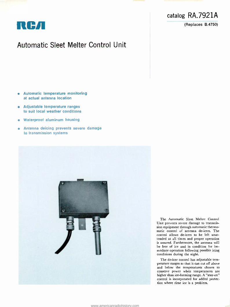
RCA Automatic Sleet Melter Control Unit
Automatic temperature monitoring at actual antenna location
Adjustable temperature ranges to suit local weather conditions
Waterproof aluminum housing
Antenna deicing prevents severe damage to transmission systems
catalog RA.7921A (Replaces B.4750)
The Automatic Sleet Metter Control Unit prevents severe damage to transmis- sion equipment through automatic thermo- static control of antenna de- icers. The control allows de -icers to be left unat- tended at all times and proper operation is assured. Furthermore, the antenna will be free of ice and in condition for im- mediate operation following possible icing conditions during the night.
The de -icer control has adjustable tem- perature ranges so that it can cut off above and below the temperatures chosen to conserve power when temperatures are higher than ice -forming range. A "stay -on" control is incorporated for added protec- tion where rime ice is a problem.
www.americanradiohistory.com

RA.7921 A
Senses at Antenna Altitude The control unit mounts at the top of
the tower or, preferably, at the midpoint of the antenna on larger antennas. Con- siderable temperature variations often exist between the antenna at the tower top and the ground level, so that ice may form on the antenna while the temperature on the ground remains above the freezing point.
Weather -Tight Construction The control unit is housed in a small
cast -aluminum box. A waterproof cover, sealed with a neoprene gasket and a con- venient mounting bracket are furnished. Adjustable terminal connections for selec- tion of temperature ranges are provided.
Only Four Connections A four -conductor cable, six feet long, is
furnished. The cable should terminate in an appropriate junction box where connections are made to the main cable run down the tower. Two of these four conductors connect to 117 volts (ac) for the relay coils; the other two are for the control circuit. The station is required to furnish the connecting cable from the transmitter building to the termination of the six -foot cable furnished with the con- trol unit, as well as the actual relay contactors to switch power to the sleet melters.
Various types of antennas, methods of de -icer connections, etc., make it imprac- tical to furnish the power relay contactors required with the Control Unit. The con- tacts of the MI -27369 are rated at 10 amperes which is more than adequate for contactor control.
Specifications Automatic Temperature Limits (Adjustable):
Upper Limit 32° or 40 °F (0 °C or 4.5 °C Lower Limit 10° or 20 °F, or no- cut-off
(- 12.6 °C or -6.6 °C) Power Line Requirements 117 V, 60 Hz Deicer Control Relay Contact Rating 10 A Dimensions 61/2" x 41/2" x 3" (165, 114, 76 mm) Weight (approx.) 5 lbs. (2.27 kg) Finish Weatherproof cast -aluminum enclosure
Ordering Information Automatic Sleet Melter Control Ml- 27369A
www.americanradiohistory.com

11CR
RADIO EQUIPMENT
PRICE LIST
Issued July 1, 1973
Prices listed here are valid only within the United States and are FOB our plant or warehouse. Any applicable taxes not included unless noted otherwise.
Reference Number
RA.9998A
All sales are subject to RCA's Standard Terms and Conditions of Sale which are available upon request from your Broadcast Equipment Field Sales Representative.
Prices subject to change without notice.
www.americanradiohistory.com
Catalog Number
Type Number Description Price
AM TRANSMITTERS, EXCITERS ES-560947 BTA-1S 250/500W AM Transmitter $ 6,595.00 ES-560650 BTA-1S 1000W AM Transmitter 6,895.00 MI-560657 Power Cutback Kit (250 or 500W) 600.00 MI-560658 Power Adjust Kit, Remote 240.00 ES-560655 Spare Tubes Kit, Complete Set' 229.00 ES-560656 Spare Tubes Kit, Recommended Sparest 116.00 MI-34309-8 Blower Kit, High Altitude 395.00 ES-562200 BTA-1 N 1 1 kW AM Transmitter 4,895.00 ES-562201 Spare Tubes Kit, Recommended Sparest 260.00 ES-562202 Spare Tubes Kit, Complete Set' 295.00 MI-561301 Power Cutback Kit 260.00 MI-561302 Power Adjust Kit, Remote 200.00 ES-560676A BTA-5L1 5 kW AM Transmitter= 22,995.00 ES-561009 Power Cutback Kit, Two Level 2,450.00 ES-561009A Power Cutback Kit, Three Level 3,300.00 ES-560680 Spare Tubes Kit, Complete Sett 945.00 ES-560682 Spare Tubes Kit, Recommended Sparest 473.00 ES-560946 Conversion Kit, BTA -5L1 to BTA -10L1 (Price approximate) 3,995.00 ES-560961 Protection Kit, Transmission Line 1,360.00 ES-560677A BTA-10L1 10 kW Am Transmitter, 10,000W 24,995.00 ES-561009 Power Cutback Kit, Two Level 2,450.00 ES-561009A Power Cutback Kit, Three Level 3,300.00 ES-560679 Spare Tubes Kit, Complete Sett 1,232.00 ES-560681 Spare Tubes Kit, Recommended Spares' 616.00 ES-560961 Protection Kit, Transmission Line 1,360.00
BTA-20L1 20 kW AM Transmitter 59,990.00 ES-560679(2) Tubes Kit, Complete Sett 2,464.00 ES-560752A(2) Tubes Kit, Recommended Spares' 1,232.00 ES-27221D BTA-50J 50 kW AM Transmitter, 50,000W2 99,995.00 ES-560948 Power Cutback Kit, Two Level (Price approximate) 5,950.00 ES-560949 Power Cutback Kit, Three Level (Price approximate) 7,950.00 ES-27222E Spare Tubes Kit, Complete Set 3,490.00 ES-27223D Spare Tubes Kit, Recommended Spares 1,745.00 ES-560752A BTE-20A Exciter, Spare, Ampliphase, Solid State (For BTA- 5L1/- 10L1/ -50J only) 4,980.00 ES-561305 Switch, Changeover, Exciter (For above exciter only; price approx.) . . 1,500.00 MI-561003A Frame, for BTE -20A Exciter 770.00 MI-561004A Module, Power Supply, for BTE -20A Exciter 1,225.00 MI-561005A Module, Regulator, for BTE -20A Exciter 790.00 MI-561006A Module, Oscillator, for BTE -20A Exciter 690.00 MI-561007A Module, Modulator, for BTE -20A Exciter 1,310.00 MI-561020 Panel, Blank, for BTE -20A Exciter 45.00 MI-27592 Crystal Oscillator, Solid State (for BTA -IS) 295.00
TUBE HOUR METERS (For AM or FM Transmitters) MI-27896-1 Meter, Elapsed Time, 230V, 60 Hz 52.00 MI-27896-2 As Above, but for 230V, 50 Hz 52.00 MI-34684-1 Meter, Elapsed Time, 230V, 60 Hz 50.00 MI-34684-2 As Above, but for 115V, 60 Hz 50.00 MI-34684-3 As Above, but for 230V, 50 Hz 50.00 MI-34684-4 As Above, but for 115V, 50 Hz 50.00 MI-561018-1 Meter, Elapsed Time, 230V, 60 Hz 20.00 MI-561018-2 As Above, but for 115V, 60 Hz 20.00 MI-561018-3 As Above, but for 230V, 50 Hz 20.00 MI-561018-4 As Above, but for 115V, 50 Hz 20.00
AM MONITORS MI-560767-1 BW-50 Frequency and Modulation Monitor (115V power) 1,500.00 M1-560767-2 BW-50 As Above but for 230V power 1,500.00 MI-560767-1X BW-50X Extended Range BW -50 (115V power) 1,895.00 MI-560767-2X BW-50X As Above but for 230V power 1,895.00 M1-560762-1 BW-60 RF Amplifier for BW -50 (115V power) 450.00 MI-560762-2 BW-60 As Above but for 230V power 450.00 MI-560896-1 Panel, Remote Metering (for BW -50, in -plant metering only) .. ... . 195.00 MI-561325 Antenna, Shielded Loop (for BW -60) 225.00
'Tube kits sold only with transmitter. =Available in parallel /redundant configuration. Prices on request.
www.americanradiohistory.com

Catalog Number
Type Number Description Price
RF AMMETERS AND ANTENNA CURRENT METERS MI-27712- Ammeter, RF (Specify scale) $ 97.00 M I-27644A- Ammeter, RF (Specify scale) 59.00 MI-27644B- Ammeter, RF (Specify scale) 59.00 MI-7157H- Ammeter, RF (Specify scale) 99.00
Air Alert 1 Receiver, Conelrad, Miratel 200.00 MI-560758 Autoformer, Three Phase, 360/240V, 35kVA 1,595.00
FM TRANSMITTERS, EXCITERS ES-560631 BTE-15A Exciter System -Monophonic only 3,410.00 ES-560632 BTE-15A Exciter System -Mono and one SCA Channel 4,070.00 ES-560633 BTE-15A Exciter System -Mono and two SCA Channels 4,730.00 ES-560634 BTE-15A Exciter System -Stereo only 4,670.00 ES-560635 BTE-15A Exciter System -Stereo and one SCA Channel 5,330.00 ES-560636 BTE-15A Exciter System -Stereo and two SCA Channels 5,990.00 MI-560734 Plugs, Connector (for BTE -15A only) 20.00 MI-560717 Crystal, with Oven, Spare tor BTE -15A 74.00 MI-560717A Oven, Crystal (less crystal) 50.00
MI-560712 Module, "FM Generator" (for BTE -15A) 1,665.00 MI-560713 BTS -1 B Module, "Stereo Generator" (for BTE -15A) 1,260.00 MI-560714 BTX-1B Module, "SCA Generator" (for BTE -15A) 660.00 MI-560711 Main Frame, Module (for BTS -1B only, less BTS -1B module) 600.00 MI-560720 Main Frame, Module (for BTX -1B only, less BTX -1B modules) 625.00 M1-560715 Panel, Blank (for BTE -15A Frame, BTX -1B size panel) 36.00 MI-560716 Adapter, Mono Input, for BTE -15A 395.00 MI-560721 Filter, Audio, Lowpass 68.00
MI-560639 BTS -1 B Stereo Generator System, self -powered, rack mount 1,650.00 MI-560640 BTX-1B SCA Generator System, self -powered, rack mount, one BTX -1B incl. 1,205.00 MI-561641 BTX-1B As Above, but with two BTX -1B Generators 1,795.00
ES-560698 BTE -10AT 10W FM Transmitter with cabinet 3,595.00 ES-560698A BTE -10AT As Above, less cabinet (rack mount) 3,440.00 ES-27279D BTF -1 E2 1 kW FM Transmitter:
Mono only 8,070.00 Mono plus one SCA 8,730.00 Mono plus two SCA 9,390.00 Stereo only 9,330.00 Stereo plus one SCA 9,990.00 Stereo plus two SCA 10,650.00
ES-34296A Spare Tubes Kit, Complete Set3 200.00
ES-560646 BTF-1 /1 E2 1/1 kW FM Transmitter, Single Exciter: Mono only 13, 620.00 Mono plus one SCA 14, 280.00 Mono plus two SCA 14,940.00 Stereo only 14,880.00 Stereo plus one SCA 15, 540.00 Stereo plus two SCA 16, 200.00
ES-560648 Spare Tubes Kit, Complete Set3 400.00 MI-27558A Kit, Power Output Control, Remote 247.00
ES-560647 BTF-1 + 1E2 2 kW FM Transmitter, Single Exciter: Mono only 15,0 75.00 Mono plus one SCA 15 735.00 Mono plus two SCA 16.395.00 Stereo only 16 335.00 Stereo plus one SCA 16 995.00 Stereo plus two SCA 17.655.00
ES-560648 Spare Tubes Kit, Complete Set3 400.00
ES-560915 BTF-3E1 3 kW FM Transmitter, Three -Phase Power: Mono only 13 495.00 Mono plus one SCA 14.155.00 Mono plus two SCA 14, 815.00 Stereo only 14,755.00 Stereo plus one SCA 15,415.00 Stereo plus two SCA 16,075.00
ES-560920 Spare Tubes Kit, Complete Set3 313.00
'Tube kits sold only with transmitter.
www.americanradiohistory.com

Catalog Number
Type Number Description Price
FM TRANSMITTERS (continued) ES-560915A BTF-3E1 3 kW FM Transmitter, Single -Phase Power:
Mono only $13,895.00 Mono plus one SCA 14,555.00 Mono plus two SCA 15, 215.00 Stereo only 15,155.00 Stereo plus one SCA 15,815.00 Stereo plus two SCA 16,475.00
ES-560920 Spare Tubes Kit, Complete Sets 313.00 MI-561026 Coupler, Directional, Exciter Output 64.00 MI-561023 Control, Power, Remote 64.00 CB Factory Installation of MI- 561023 177.00 ES-560923 BTF-3/3E1 3/3 kW FM Transmitter, Single Exciter, Three -Phase Power:
Mono only (Price approximate) 29,995.00 Mono plus one SCA (Price approximate) 30,655.00 Mono plus two SCA (Price approximate) 31,315.00 Stereo only (Price approximate) 31,255.00 Stereo plus one SCA (Price approximate) 31,915.00 Stereo plus two SCA (Price approximate) 32,575.00
ES-560920(2) Spare Tubes Kit, Complete Sets 626.00 MI-561026 Coupler, Directional, Exciter Output 64.00 MI-561023 Control, Power, Remote 64.00 CB Factory Installation of MI- 561023 177.00 ES-560600 BTF-3/3E1 3/3 kW FM Transmitter, Single Exciter, Single -Phase Power:
Mono only (Price approximate) 30,995.00 Mono plus one SCA (Price approximate) 31,655.00 Mono plus two SCA (Price approximate) 32,315.00 Stereo only (Price approximate) 32,255.00 Stereo plus one SCA (Price approximate) 32,915.00 Stereo plus two SCA (Price approximate) 33,575.00
ES-560920(2) Spare Tubes Kit, Complete Sets 626.00 MI-561026 Coupler, Directional, Exciter Output 64.00 MI-561023 Control, Power, Remote 64.00 CB Factory Installation of MI- 561023 177.00
ES-560922 BTF-3+3E1 6 kW FM Transmitter, Single Exciter, Three -Phase Power: Mono only (Price approximate) 34,195.00 Mono plus one SCA (Price approximate) 34,855.00 Mono plus two SCA (Price approximate) 35, 515.00 Stereo only (Price approximate) 35,455.00 Stereo plus one SCA (Price approximate) 36,115.00 Stereo plus two SCA (Price approximate) 36,775.00
ES-560920(2) Spare Tubes Kit, Complete Sets 626.00 MI-561026 Coupler, Directional, Exciter Output 64.00 MI-561023 Control, Power, Remote 64.00 ES-560922A BTF-3+3E1 6 kW FM Transmitter, Single Exciter, Single -Phase Power:
Mono only (Price approximate) 34,995.00 Mono plus one SCA (Price approximate) 35,655.00 Mono plus two SCA (Price approximate) 36,315.00 Stereo only (Price approximate) 36,255.00 Stereo plus one SCA (Price approximate) 36,915.00 Stereo plus two SCA (Price approximate) 37,575.00
MI-561920(2) Spare Tubes Kit, Complete Sets 626.00 MI-561026 Coupler, Directional, Exciter Output 64.00 MI-561023 Control, Power, Remote 64.00 CB Factory Installation of MI- 561023 177.00 ES-560916 BTF-5E2 5 kW FM Transmitter:
Mono only 14,995.00 Mono plus one SCA 15,655.00 Mono plus two SCA 16,315.00 Stereo only 16,255.00 Stereo plus one SCA 16,915.00 Stereo plus two SCA 17,575.00
ES-560920 Spare Tubes Kit, Complete Sets 313.00
'Tube kits sold only with transmitter.
www.americanradiohistory.com

Catalog Number
Type Number Description Price
MI-561026 MI-561023 CB
ES-560962
ES-560920(2) MI-561026 MI-561023 CB
ES-560923
ES-560920(2) MI-561026 MI-561023 CB
ES-560600
ES-560607
ES-560603
ES-560610
ES-560637
ES-560273
ES-560601
ES-560608
BTF-5+5E2
BTF-5/5E2
BTF-5E1
BTF-5/5E1
BTF-5+5E1
BTF-10E1
ES-560604 BTF-10/10E1
FM TRANSMITTERS (continued)
Coupler, Directional, Exciter Output Control, Power, Remote Factory Installation of MI- 561023
10 kW FM Transmitter, Single Exciter: Mono only (Price approximate) Mono plus one SCA (Price approximate) Mono plus two SCA (Price approxifate) Stereo only (Price approximate) Stereo plus one SCA (Price approximate) Stereo plus two SCA (Price approximate)
Spare Tubes Kit, Complete Sets Coupler, Directional, Exciter Output Control, Power, Remote Factory Installation of MI- 561023
5/5 kW FM Transmitter, Single Exciter: Mono only (Price approximate) Mono plus one SCA (Price approximate) Mono plus two SCA (Price approxifate) Stereo only (Price approximate) Stereo plus one SCA (Price approximate) Stereo plus two SCA (Price approximate)
Spare Tubes Klt, Complete Seta Coupler, Directional, Exciter Output Control, Power, Remote Factory Installation of MI- 561023
5 kW FM Transmitter: Mono only Mono plus one SCA Mono plus two SCA Stereo only Stereo plus one SCA Stereo plus two SCA
Spare Tubes Kit, Complete Sets
5/5 kW FM Transmitter, Single Exciter: Mono only Mono plus one SCA Mono plus two SCA Stereo only Stereo plus one SCA Stereo plus two SCA
Spare Tubes Kit, Complete Sets
10 kW FM Transmitter, Single Exciter: Mono only Mono plus one SCA Mono plus two SCA Stereo only Stereo plus one SCA Stereo plus two SCA
Spare Tubes Kit, Complete Sets
10 kW FM Transmitter: Mono only Mono plus one SCA Mono plus two SCA Stereo only Stereo plus one SCA Stereo plus two SCA
Spare Tubes Kit, Complete Sets
10/10 kW FM Transmitter: Mono only Mono plus one SCA Mono plus two SCA Stereo only
'Tube kits sold only with transmitter.
64.00 64.00
177.00
37,195.00 37,855.00 38,515.00 38,455.00 39,115.00 39,775.00
626.00 64.00 64.00
177.00
32,995.00 33,655.00 34,315.00 34,255.00 34,915.00 35,575.00
626.00 64.00 64.00
177.00
16,650.00 17,310.00 17,970.00 17,910.00 18,570.00 19,230.00
531.00
46,400.00 47,720.00 49,040.00 48,920.00 50,240.00 51,560.00 1,062.00
50,475.00 51, 795.00 53.115.00 52.995.00 54,315.00 55,635.00
1,062.00
21,895.00 22,555.00 23,215.00 23,155.00 23,815.00 24,475.00
611.00
50,715.00 52,035.00 53,355.00 53,235.00
www.americanradiohistory.com

Catalog Number
Type Number Description Price
ES-560611 - ES-560638 BTF-10-t10E1
ES-560235
ES-560602
ES-560609 MI-560307-31 CB
ES-560605
ES-560612
BTF-20E1
BTF-20/20E1
ES-560606 BTF-40E1
ES-560613
MI-561018-2 MI-561018-4 MI-560307-31 CB MI-560347-3 MI-560705 MI-560758 MI-561026 MI-561707A MI-34319-2 MI-560307-36 MI-560708A MI-560708E MI-560708B MI-560708C MI-560708D
MI-561322 MI-561323
ES-560642 ES-560643 ES-560644 ES-560645
FM TRANSMITTERS (continued) Stereo plus one SCA Stereo plus two SCA
Spare Tubes Kit, Complete Set3
20 kW FM Transmitter: Mono only Mono plus one SCA Mono plus two SCA Stereo only Stereo plus one SCA Stereo plus two SCA
Spare Tubes Kit, Complete Set; ...... .. .
20 kW FM Transmitter: Mono only Mono plus one SCA Mono plus two SCA Stereo only Stereo plus one SCA Stereo plus two SCA
Spare Tubes Kit, Complete Set3 AM Noise Reduction Kit Factory Installation of MI- 560307 -31
20/20 kW FM Transmitters: Mono only Mono plus one SCA Mono plus two SCA Stereo only Stereo plus one SCA Stereo plus two SCA
Spare Tubes Kit, Complete Set3
40 kW FM Transmitter: Mono only Mono plus one SCA Mono plus two SCA Stereo only Stereo plus one SCA Stereo plus two SCA
Spare Tubes Kit, Complete Set3
FM TRANSMITTER MISCELLANEOUS ACCESSORIES Meter, Elapsed Time, 115V, 60 Hz As Above, but for 50 Hz AM Noise Reduction Kit Factory Installation of above kit High Altitude Blower Kit Mounting Kit for above Three -Phase Autoformer, 360/240V, 50/60 Hz, 35 kVA Coupler, Directional, Exciter Output Probe, Monitor, for 31/2-inch T/L Transformer, Filament, 50 Hz (for BTF -1E2) Manometer Directional Coupler, 61/2", 50 ohms, 40 kW (Price approximate) As Above, but 31/2" (Price approximate) As Above, but 20 kW (Price approximate) As Above, but 10 kW (Price approximate) As Above, but 5 kW (Price approximate)
$54,555.00 55,875.00 1,222.00
55, 215.00 56,535.00 57,855.00 57,735.00 59,555.00 60,375.00
1,222.00
29,225.00 29,885.00 30,545.00 30,485.00 31,145.00 31,805 00
767.00 605.00 250.00
63,440.00 64, 760.00 66,080.00 65,960.00 67,280.00 68,600.00 1,534.00
66,520.00 67,840.00 69,160.00 69,040.00 70,360.00 71,680.00
1,534.00
20.00 20.00
605.00 250.00 278.00 300.00
1,595.00 64.00 64.00 70.00 60.00
450.00 300.00 300.00 300.00 300.00
Connectors, Set, for BTS -1B System (ES- 560639) 10.00 As Above, but for BTX -1B System (ES- 560640/1) ............. .. 10.00
POWER CONVERSION KITS Converts BTF -5E /E1 to BTF- 10E /E1 Converts BTF -5E /E1 to BTF- 20E /E1 Converts BTF- 10E /E1 to BTF- 20E /E1 Converts BTF -20E1 to BTF -40E1 (Mono only)
'Tube kits sold only with transmitter.
6,500.00 13,455.00
8,310.00 40,895.00
www.americanradiohistory.com

Catalog Number
MI-560735 MI-560736 MI-560740 MI-560741 MI-560745 MI-560746 MI-560738
ES-561446-1 ES-561446-4 ES-561446-5 ES-561446-6 ES-561446-8 ES-561446-9 ES-561446-10 ES-561446-11 ES-561446-13 ES-561446-14 ES-561446-15 ES-561446-16
ES-561157 ES-561158-26 ES-561158-110 MI-561181-1
ES-561438 ES-561443-1 ES-561443-2 ES-561443-3 MI-561444
ES-561154
MI-27516 MI-27519 MI-27544 MI-561179 MI-561470 MI-561471-1 MI-561482 MI-561483
MI-561458 MI-561459 MI-561460 MI-561461 MI-561462 MI-561463 MI-561464 MI-561465 ES-561156 MI-561469 MI-561184 MI-561182 MI-561479 MI- 561479(Mod
Type Number Description
FM MONITORS
BW -75A Freq. & Mod. Monitor - Panel, Remote Metering (for BW -75A) BW -85A Stereo Freq. & Mod. Monitor
Panel, Remote Metering (for BW -85A) BW -9- 5A SCA Freq. & Mod. Monitor (Each add'I subcarrler freq.: $20.00) - Panel, Remote Metering (for BW -95A) BW -100B RF Amplifier (for BW -75A)
BTR-30A1 BTR-30A1 BTR-30A1 BTR-30A1 BTR-30A1 BTR-30A1 BTR-30A1 BTR-30A1 BTR-30A1 BTR-30A1 BTR-30A1 BTR-30A1
BTR-15BW BTR-15BR BTR-15BR
BTC-2
ADP -220
PLC -1
PVK-- 1
PV K-2 RMK-1 RFK-1 RFK-2 R F K-3 MIU-1 MRU-1 MMA-1 CSA-3 TLK-1 LVK-1 MBB-1 TSK-1 SCS-2 TAU-1
TMR- -1
MSC-1 MSC-1 (Mod)
REMOTE CONTROL EQUIPMENT
Remote Control System Remote Control System Remote Control System Remote Control System Remote Control System Remote Control System Remote Control System Remote Control System Remote Control System Remote Control System Remote Control System Remote Control System
Remote Control System Remote Control System Remote Control System Option, Internal Telemetry Subcarrier (for BTR -15BR)
CONTROL AND EXTENSION METER PANELS
Panel, Extension Control /Metering (For local control only) .
Panel, Meter, One Meter Panel, Meter, Two Meters Panel, Meter, Three Meters Meter (Please specify full -scale calibration)
AUTOMATIC LOGGING EQUIPMENT
Printer, Data, Digital, Automatic
REMOTE CONTROL ACCESSORIES
Pickup, Voltage, AC, 115/230V Unit, Monitoring and Control, Tower Lights Unit, Monitor, Tower Lighting Converter, Power -to- Linear Panel, Relay (for eight MI- 561471) Relay, DPDT, 120Vac Coil (for above) Kit, Sampling, Plate -Voltage, 0 -10kV Kit, Sampling, Plate -Voltage, 10 -20kV Kit, Motor, Reversible, with adj. clutch Kit, Sampling, T /L, AM Frequencies Kit, Sampling, T /L, FM, 31 /e" Kit, Sampling, T /L, FM, 13/4"
Unit, Insertion, Metering Unit, Recovery, Metering Adaptor, Modulation Monitor Amplifier, Chopper -Stabilized Kit, Tower Light Monitor Kit, Sampling, Line Voltage Kit, Sampling, Plate Voltage Kit, Sensing, Temperature System, Status Indicator Frame, Tolerance Alarm Module, Tolerance Alarm (for TAU -1 above) Receiver, FM, Telemetry Combiner, Multi- System As Above, but for use with subcarrier generator
Price
$ 1,550.00 145.00
1,350.00 145.00
1,250.00 145.00 400.00
2,995.00 3,095.00 3,095.00 3,095.00 3,315.00 3,095.00 3,095.00 3,095.00 3,155.00 2,925.00 2,925.00 2,925.00
1,595.00 1,995.00 1,995.00
125.00
495.00 90.00
120.00 150.00 40.00
7,350.00
152.00 125.00 120.00 235.00
34.00 9.00
30.00 60.00 83.00 38.00 38.00 38.00
195.00 195.00 105.00 135.00 30.00 35.00 90.00 75.00
1,795.00 395.00 65.00
190.00 750.00 800.00
www.americanradiohistory.com
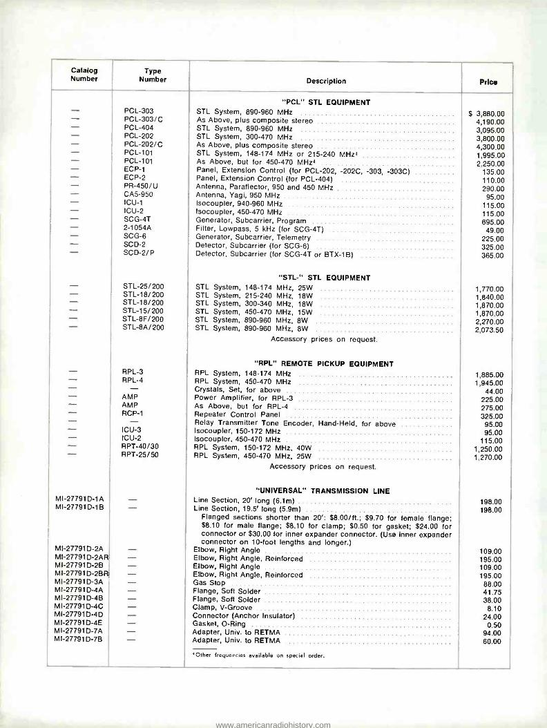
Catalog Type Number Number
- PCL-303 - PCL-303/C - PCL-404 - PCL-202 - PCL-202/C - PCL-101 - PCL-101 - ECP-1 - ECP-2 - PR-450/U - CA5-950 - ICU-1 - ICU-2 SCG-4T - 2-1054A - SCG-6 - SCD-2 - SCD-2/P
- STL-25/200 - STL-18/200 - STL-18/200 - STL-15/200 - STL-8F/200 - STL-8A/200
MI-277910-1A MI-27791D-1B
M I-27791 D-2A M I-27791 D-2AR MI-27791D-2B MI-27791 D-2BR MI-27791D-3A MI-27791D-4A MI-27791D-4B MI-27791D-4C MI-27791D-4D MI-27791D-4E MI-27791D-7A MI-27791D-7B
RPL -3 RPL -4
AMP AMP RCP -1
ICU -3 ICU -2 RPT -40/30 RPT -25/50
Description Price
"PCL" STL EQUIPMENT STL System, 890 -960 MHz As Above, plus composite stereo STL System, 890 -960 MHz STL System, 300 -470 MHz As Above, plus composite stereo STL System, 148 -174 MHz or 215 -240 MHz+ As Above, but for 450 -470 MHz Panel, Extension Control (for PCL -202, -202C, -303, -303C) Panel, Extension Control (for PCL -404) Antenna, Paraflector, 950 and 450 MHz Antenna, Yagi, 950 MHz Isocoupler, 940 -960 MHz Isocoupler, 450 -470 MHz Generator, Subcarrier, Program Filter, Lowpass, 5 kHz (for SCG -4T) Generator, Subcarrier, Telemetry Detector, Subcarrier (for SCG -6) Detector, Subcarrier (for SCG -4T or BTX -1B)
"STL -" STL EQUIPMENT STL System, 148 -174 MHz, 25W STL System, 215 -240 MHz, 18W STL System, 300 -340 MHz, 18W STL System, 450 -470 MHz, 15W STL System, 890 -960 MHz, 8W STL System, 890 -960 MHz, 8W
Accessory prices on request.
$ 3,880.00 4,190.00 3,095.00 3,800.00 4,300.00 1,995.00 2,250.00
135.00 110.00 290.00 95.00
115.00 115.00 695.00 49.00
225.00 325.00 365.00
1,770.00 1,840.00 1,870.00 1,870.00 2,270.00 2,073.50
"RPL" REMOTE PICKUP EQUIPMENT RPL System, 148 -174 MHz 1,885.00 APL System, 450 -470 MHz 1,945.00 Crystals, Set, for above 44.00 Power Amplifier, for RPL -3 225.00 As Above, but for RPL -4 275.00 Repeater Control Panel 325.00 Relay Transmitter Tone Encoder, Hand -Held, for above 95.00 Isocoupler, 150 -172 MHz 95.00 Isocoupler, 450 -470 MHz 115.00 RPL System, 150 -172 MHz, 40W 1,250.00 RPL System, 450 -470 MHz, 25W 1,270.00
Accessory prices on request.
"UNIVERSAL" TRANSMISSION LINE Line Section, 20' long (6.1m) Line Section, 19.5' long (5.9m)
Flanged sections shorter than 20': $8.00 /ft.; $9.70 for female flange; $8.10 for male flange; $8.10 for clamp; $0.50 for gasket; $24.00 for connector or $30.00 for inner expander connector. (Use inner expander connector on 10 -foot lengths and longer.)
Elbow, Right Angle Elbow, Right Angle, Reinforced Elbow, Right Angle Elbow, Right Angle, Reinforced Gas Stop Flange, Soft Solder Flange, Soft Solder Clamp, V- Groove Connector (Anchor Insulator) Gasket, O -Ring Adapter, Univ. to RETMA Adapter, Univ. to RETMA
'Other frequencies available on special order.
198.00 198.00
109.00 195.00 109.00 195.00 88.00 41.75 38.00
8.10 24.00
0.50 94.00 60.00
www.americanradiohistory.com

Catalog Number
Type Number
MI-27791D-7C MI-27791D-8A MI-27791D-8B MI-27791-14 MI-27791-16 MI-19089-15 MI-19089-16 MI-19089-18
MI-19089-1E MI-19089-1F
MI-19089-2A MI-19089-2C MI-19089-2CR MI-19089-4 MI-19089-6 MI-19089-10A MI-19089-14 MI-19089-15 MI-19089-16 MI-19089-17 MI-19089-18 MI-19089-19 MI-19089-20 MI-19089-21 MI-19089-24 MI-19089-25 MI-19089-26 MI-19113C-10 MI-19113C-19 MI-27988-5D MI-27988-5C MI-27988-4A MI-27988-4B MI-27988-4C MI-27988-7A MI-27988-7E
MI-19113C-1 MI-19113C-1 NF
MI-19113C-8 M I-19113C-8N B MI-19113C-9 MI-19113C-11 MI-19113C-18 MI-19113C-18NF
MI-19313-1H MI-19313-1 NF
M I-19313-1 SFH M I-19313-1 BH MI-19313-1 BSFH MI-19313-2 MI-19313-2R
Description Price
"UNIVERSAL" TRANSMISSION LINE (continued)
Adapter, Univ. Male End Cap, Female End Cap, Male Flange, Female Flange, Male Guide, Cutoff Guide, Cutoff Grease, Silicone
BOLT- FLANGED TRANSMISSION LINE
Line Section, 20' long (6.1m) Line Section, 19.5' long (5.9m)
Flange section shorter than 20': $8.00 /ft plus: $17.75 each flange; $2.30 each hardware set; $0.60 each gasket; $24.75 for standard con- nector OR $36.00 for expansion connector. (Use expansion connector on 10 -foot lengths and longer.)
Elbow, Right Angle, Male Elbow, Right Angle, Female Elbow, Right Angle, Reinforced Gas Stop Elbows, Tandem Connector, Anchor Insulator Flange, Soft Solder Guide, Cutoff Guide, Cutoff Reducer, to Type N Connector Grease, Silicone Adapter, "N" to "HN" Tool, Anchor Insulator Removal Reducer, to "HN" Connector Adapter, EIA to Univ. Male Adapter, EIA to Univ. Female Cap, End Seal Gasket, O -Ring Kit, Hardware Reducer, Quick -Step Reducer, Quick -Step Adapter, Inner Connector Adapter, Inner Connector Flange, Mechanical Adapter, Section Adapter, Male -to -Male
STEATITE INSULATED, 51.5 -OHM TRANSMISSION LINE
Line Section, 20' long (6.1m), Flanged As Above, less flanges
Lengths less than 20' long: $8.00 /ft plus: $14.25 each fixed flange; $2.30 each connector; $2.30 each hardware set.
Coupling, Unflanged As Above, less Inner Connector Inner Conductor, Splicing, 20' long Connector, Inner Conductor Elbow, Right Angle, Flanged As Above, less flanges
TEFLON -INSULATED, 51.5 -OHM TRANSMISSION LINE
Line Section, 20' long (6.1m) Line Section, 20' long (6.1m), less flanges
Lengths less than 20' long: $8.00 /ft plus $14.25 for each fixed flange; $2.30 for each hardware kit; $2.80 each connector OR $12.00 for expander connector. (Use expander on lengths greater than 10 feet.)
Line Section, 20' long (6.1m) Line Section, 19.5' long (5.9m) Line Section, 19.5' long (5.9m) Elbow, Right Angle As Above, Reinforced
$ 27.50 56.00 44.25 9.70 8.10
13.25 7.40 3.50
210.00 210.00
128.00 114.00 204.00 105.00 233.00
24.75 38.25 13.25 7.40
124.00 3.50
33.75 12.00
123.00 94.00 60.00 63.00
0.60 2.30
80.00 87.00 15.25 13.50 32.25 41.25 38.75
187.00 158.00
9.80 7.00
28.75 2.30
90.00 65.00
198.00 158.00
194.00 198.00 205.00 90.00
173.00
www.americanradiohistory.com

Catalog Number
M I-19313-2N F
MI-19313-8 M I-19313-8N B MI-27988-4B MI-19113C-5 MI-19113C-51 MI-19113C-54 MI-19113C-55 MI-19089-15 MI-19113C-60 MI-19113C-6 MI-19113C-7 MI-27988-5A MI-19113C-58 MI-19313-11 MI-19313-10 MI-19113C-13
MI-561565-1A
MI-27791K-1A
MI-561579-1A
MI-561565-2A MI-27791 K-2A MI-561579-2A MI-561565-4A MI-27791K-4A MI-561579-4A MI-561565-4B MI-27791K-4B MI-561579-4B MI-561565-7A MI-27988-4C MI-27791K-78 MI-27791K-7A MI-561579-7A MI-561565-5B MI-27791K-5A MI-561579-5B MI-561565-5A MI-561579-5A MI-561579-6T MI-561565-8A MI-27988-4A MI-27988-4B MI-561579-8A MI-561565-4C MI-27791K-4C MI-561579-4C
MI-19313-11 MI-27988-5C MI-27988-5B M I-27988-5D MI-27988-5A MI-27988-5E M I-27988-7E MI-27988-7D MI-27988-7C MI-27988-7A MI-27988-7B MI-27988-7G MI-27988-7F
Type Number Description Price
TEFLON -INSULATED, 51.5 OHM TRANSMISSION LINE (continued) Elbow, Right Angle, less flanges Coupling, Unflanged Coupling, Unflanged, less connector Adapter, Inner Connector Gas Stop Guide, Cutoff Guide, Cutoff Flange, Soft Solder Guide, Cutoff Flange, Mechanical Reducer Reducer Reducer Reducer Bushing, Adapter Adapter, Inner Conductor End Cap
UNFLANGED, 50 -OHM TRANSMISSION LINE Line Section, 20' long (6.1m)
(Lengths less than 20': $3.70 /foot) Line Section, 20' long (6.1m)
(Lengths less than 20': $7.25 /foot) Line Section, 20' long (6.1m)
(Lengths less than 20': $23.00 /foot) Elbow, Right Angle Elbow, Right Angle Elbow, Right Angle Coupling Coupling Coupling Connector, Inner Conductor Connector, Inner Conductor Connector, Inner Conductor Adapter Adapter Adapter Adapter Adapter Reducer Reducer Reducer Reducer Reducer Transformer- Adapter Adapter, Inner Conductor Adapter, Inner Conductor Adapter, Inner Conductor Adapter, Inner Conductor Clamp, Worm -Drive Clamp, Worm -Drive Clamp, Worm -Drive
SPECIAL ADAPTERS Adapter, Bushing Reducer Reducer Reducer Reducer Reducer Adapter, Male -to -Male Adapter, Male -to -Male Adapter, Male -to -Male Adapter Adapter Adapter Adapter, Male -to -Male
$ 65.00 10.00 7.00
13.50 74.00 7.00 8.90
44.50 13.25 35.75 57.00 46.00 78.00
124.00 1.30 3.50
14.75
88.00
143.00
457.00
34.00 55.00
165.00 12.00 9.70
44.00 6.80 3.10
22.50 16.00 32.25 20.50 29.50 85.00 26.00
124.00 238.00 87.00
218.00 340.00
6.80 15.25 13.50 89.00 0.50 0.75 1.00
2.30 87.00 41.75 80.00 78.00 65.00 38.75 26.50 17.00 41.25 34.75 27.00 18.25
www.americanradiohistory.com

Catalog Number
Type Number Description Price
SEMI -RIGID TRANSMISSION LINE
HJ4-50 Air Dielectric, 1/2" Dia., per foot $ 1.22
HJ5-50 Air Dielectric, 7 /e" Dia., per foot 2.32
HJ7-50 Air Dielectric, 15/8" Dia., per foot 5.06 HJ8-50 Air Dielectric, 3" Dia., per foot 10.00 FHJ1-50 Foam Dielectric, 1/4" Dia., per foot 0.40 FHJ2-50 Foam Dielectric, Ye" Dia., per foot 0.57 FHJ4-50 Foam Dielectric, 1/2" Dia., per foot 0.74 FHJ5-50 Foam Dielectric, 7 /e" Dia., per foot 1.90
FHJ7-50 Foam Dielectric, 1%" Dia., per foot 4.32 41U UHF Jack (Female) 9.50 41P UHF Plug (Male) 9.50 41N Type N Jack (Female) 9.50 41W Type N Plug (Male) 9.50 13212-2 Adapter, End Terminal 12.00
12395-1 Wraplock, Stainless Steel (100' or 30 m) 15.00 27290 Tie Wires, Copperweld (Qty 20) 3.00 11662-3 Clamp, Mounting 5.00 42U UHF Jack (Female) 11.50 42P UHF Plug (Male) 11.50 42N Type N Jack (Female) 11.50 42W Type N Plug (Male) 11.50 13212-2 Adapter, End Terminal 12.00 12395-1 Wraplock, Stainless Steel (100' or 30 m) 15.00 27290 Tie Wires, Copperweld 3.00
11662-3 Clamp, Mounting, Insulated 5.00 44AU UHF Jack (Female) 6.30 44AP UHF Plug (Male) 6.30 44AW Type N Jack (Female) 7.40 44AN Type N Plug (Male) 7.40 44AT Adapter, End Terminal 26.00 12395-1 Wraplock, Stainless Steel (100' or 30 m) 15.00 11662-3 Clamp, Mounting, Insulated 5.00 45AR Flange, EIA 26.00 45AZ Splice 26.00 45AM Type LC Plug (Male) 26.00 26892-2 Kit, Grounding 3.00 45AU UHF Jack (Female) 17.00 45AP UHF Plug (Male) 17.00 45AW Type N Jack (Female) 20.00 45AN Type N Plug (Male) 20.00 45AT Adapter, End Terminal 34.00 12395-1 Wraplock, Stainless Steel (100' or 30 m) 15.00 11662-2 Clamp, Mounting, Insulated 5.00 45AR Flange, EIA 25.00 45AZ Splice 30.00 45AM Type LC Jack (Female) 38.00 45AL Type LC Plug (Male) 38.00 40993-5 Kit, Grounding 5.00 31766-5 Kit, Hanger (Qty 10) 18.00 31768-1 Adapter, Hanger (Qty 10) 20.00 31670-1 Adapter, Hanger (Qty 10) 8.00 31670-2 Adapter, Hanger (Qty 10) 8.00 31670-3 Adapter, Hanger (Qty 10) 10.00 31670-4 Adapter, Hanger (Qty 10) 10.00 31670-5 Adapter, Hanger (Qty 10) 10.00 2061 Adapter, End Terminal 70.00 12395-1 Wraplock, Stainless Steel (100' or 30 m) 15.00 33948-3 Clamp, Mounting, Insulated 10.00 47R Flange, EIA 70.00 47Z Splice 78.00 47M Type LC Jack (Female) 78.00 47L Type LC Plug (Male) 78.00 40993-2 Kit, Grounding 5.00 31766-2 Kit, Hanger (Qty 10) 18.00 31768-1 Adapter, Hanger (Qty 10) 20.00
31670-1 Adapter, Hanger (Qty 10) 8.00
www.americanradiohistory.com

Catalog Number
Type Number Description Price
SEMI -RIGID TRANSMISSION LINE (continued) 31670-2 Adapter, Hanger (Qty 10) 8.00 31670-3 Adapter, Hanger (Qty 10) 10.00 31670-4 Adapter, Hanger (Qty 10) 10.00 31670-5 Adapter, Hanger (Qty 10) 10.00 74N Type N Jack (Female) 21.00 74W Type N Plug (Male) 21.00 12395-1 Wraplock, Stainless Steel (100' or 30 m) 15.00 26892-2 Kit, Grounding 3.00 11662-3 Hanger, Insulated 5.00 1920A Dehydrator, Automatic 820.00 878A Pump, Dry Air 100.00 858C Fittings, Nitrogen Tank 116.00 75AU UHF Jack (Female) 25.00 75AN Type N Jack (Female) 25.00 75AW Type N Plug (Male) 32.00 75AT Adapter, End Terminal 50.00 1060 Elbow, Mitre, 90- degree 40.00 12395-1 Wraplock, Stainless Steel 15.00 75AR Flange, EIA 32.00 75AG Flange, EIA, w /Gas Barrier 51.00 75AZ Splice 34.00 19256B Grip, Hoisting 15.00 40993-5 Kit, Grounding 5.00 31766-5 Kit, Hanger 18.00 31768-1 Adapter, Hanger 20.00 31670-1 Adapter, Hanger (Qty 10) 8.00 31670-2 Adapter, Hanger (Qty 10) 8.00 31670-3 Adapter, Hanger (Qty 10) 10.00 31670-4 Adapter, Hanger (Qty 10) 10.00 31670-5 Adapter, Hanger (Qty 10) 10.00 11662-2 Hanger, Insulated 5.00 1260A Barrier, Gas 38.00 1920A Dehydrator, Automatic 820.00 878A Pump, Dry Air 100.00 858C Fittings, Nitrogen Tank 116.00 87N Type N Jack (Female) 66.00 2061 Adapter, End Terminal 70.00 1061 Elbow, Mitre, 90- degree 60.00 12395-1 Wraplock, Stainless Steel (100' or 30 m) 15.00 87R Flange, EIA 64.00 87G Flange, EIA, w /Gas Barrier 76.00 87Z Splice 84.00 24312A Grip, Hoisting 19.00 40993-2 Kit, Grounding 5.00 31766-2 Kit, Hanger 18.00 31768-1 Adapter, Hanger, Angle Iron 20.00 31670-1 Adapter, Hanger (Qty 10) 8.00 31670-2 Adapter, Hanger (Qty 10) 8.00 31670-3 Adapter, Hanger (Qty 10) 10.00 31670-4 Adapter, Hanger (Qty 10) 10.00 31670-5 Adapter, Hanger (Qty 10) 10.00 33948-3 Hanger, Insulated 10.00 1261B Barrier, Gas 64.00 1920A Dehydrator, Automatic 820.00 878A Pump, Dry Air 100.00 858C Fittings, Nitrogen Tank 116.00 2062 Adapter, End Terminal 110.00 1062 Elbow, Mitre, 90- degree 100.00 78ARM Flange, EIA 110.00 78AGM Flange, EIA, w /Gas Barrier 122.00 78AZ Splice 132.00 26985A Grip, Hoisting 25.00 40993-11 Kit, Grounding 8.00 33598-3 Kit, Hanger 20.00 33981-1 Adapter, Hanger, Angle Iron 21.00 33984-1 Adapter, Hanger, Round 48.00
www.americanradiohistory.com

Catalog Number
Type Number Description Price
SEMI -RIGID TRANSMISSION LINE (continued)
33948 -2 - Hanger, Insulated $ 22.00
1262A - Barrier, Gas 112.00
1920A - Dehydrator, Automatic 820.00 878A - Pump, Dry Air 100.00 858C - Fittings, Nitrogen Tank 116.00
HANGERS AND ACCESSORIES
MI- 19313 -44 - Hanger, Fixed 13.25 MI- 19313 -47 - Hanger, Fixed 14.00 MI- 19313 -34 - Hanger, Expansion 25.50 MI- 19313 -32 - Hanger, Expansion 17.00 MI- 19313 -33 - Hanger, Expansion 17.75 MI- 19313 -41 - Hanger, Heavy Duty 48.00 MI- 19313 -37 - Hanger, Swivel 59.00 MI- 19313 -38 - Hanger, Dual Swivel 59.00 MI- 19313 -50 - Hanger, Suspension 28.25 MI- 19313 -51 - Hanger, Suspension 58.00 MI- 19313 -35 - Roller, Horizontal 16.00 MI- 19313 -36 - Brace, Lateral 9.70 MI- 19313 -17 - Anchor, Horizontal 30.25 MI- 19313 -18 - Anchor, Horizontal, Dual 60.50 MI- 19113 -16 - Kit, Extension 3.50
PRESSURIZING EQUIPMENT MI- 563170 -1 - Compressor /Dehydrator, r/z HP, 60 Hz 725.00 MI- 563170 -3 - Compressor /Dehydrator, 3/4 HP, 60 Hz 900.00 MI- 561668A - Gassing Kit A 17.00 MI- 5616686 - Gassing Kit B 35.00 MI- 561668C - Gassing Kit C 13.50 MI- 561668A -1 - Plastic Tubing 3.00 MI- 19315 -22 - Pressure Regulator 112.00
COAXIAL SWITCHES MI- 561562A - Motorized Co -Ax Switch 1,282.00 MI- 561562B - Motorized Co -Ax Switch 1,282.00 MI- 561562C - Motorized Co -Ax Switch 1,282.00 MI- 561562D - Motorized Co -Ax Switch 1,282.00 MI- 561562E - Motorized Co -Ax Switch 1,282.00 MI- 561562F - Motorized Co -Ax Switch 1,282.00 MI -27717 - Co -Ax- Switch, Three -Pole 240.00 MI -27718 - Co -Ax Switch, Seven -Pole 632.00 MI -27719 - Co -Ax- Switch, Three -Pole 472.00 MI -27720 - Co -Ax Switch, Seven -Pole 1,342.00 MI- 27912 -50 - Co -Ax- Switch, Three -Pole 243.00 MI- 561680 - Co -Ax Switch, Four -Pole 529.00 MI- 27912 -51 - Co -Ax Switch, Seven -Pole 644.00
TOWER ACCESSORIES MI -27765 - Ground Screen 120.00 MI -7112C - Choke, Lighting, Double 68.50 MI -27726 - Choke, Lighting, Triple 72.50 MI- 27728 -1 - Capacitor, Lighting Choke 4.25 MI -27741 - Weatherproof Housing 79.00 MI- 28215A -1 TI -2017 Transformer, Lighting, 1750W 340.00 MI- 28215A -2 TI -2035 Transformer, Lighting, 3500W 395.00
ANTENNA TUNING UNITS MI- 27767A BPA -21A Tuning Unit, Antenna 900.00 MI- 27767B BPA -21B Tuning Unit, Antenna 1.095.00 MI- 27767C BPA -21C Tuning Unit, Antenna 1,175.00 MI- 27767D BPA -21D Tuning Unit, Antenna 1,185.00 MI -27725 - Tuning Unit 440.00 MI- 28027C - Pickup, Remote -Meter 190.00 ES -27241 BCP -1B Kit, Isolation, Lighting 74.00 ES -27242 - Kit, Isolation, Lighting 89.00
www.americanradiohistory.com

Catalog Number
Type Number Description Price
ANTENNA TUNING UNITS (continued) ES -27243 - Kit, Isolation, Lighting $ 158.00 ES -27244 - Kit, Isolation, Lighting 168.00 MI- 27789A BPA -5A Tuning Unit, 5 kW 1,495.00 MI- 27790A BPA -10A Tuning Unit, 10 kW 1,520.00 MI- 28027C - RF Pickup Unit 190.00 MI- 27966B - RF Pickup Unit 145.00 MI- 561522 C0019 Sampling Loop 158.00 MI -27729 173 -10 -1 Sampling Loop 150.00 MI -27730 173 -11 -1 Sampling Loop 69.00 MI -27731 173 -11 -2 Sampling Loop 85.00 M150- FH1 -50 - Inductor, Isolation 235.00 M150- FHJ1 -50 - Inductor, Isolation 245.00 M150- FH2 -50 - Inductor, Isolation 255.00 M150- FHJ2 -50 - Inductor, Isolation 270.00 M135- FH4 -50 - Inductor, Isolation 305.00 M135- FHJ4 -50 - Inductor, Isolation 315.00 MI- 27029 -2 - Dummy Load, Water Cooled 870.00 MI- 27029 -3 - Dummy Load, Water Cooled 870.00 CB - Water Cooled Load Kit 3,150.00 MI -27966 - RF Pickup Unit 145.00 MI -28027 - RF Pickup Unit 190.00 MI- 27644A - Meter 59.00 MI- 27644B - Meter 59.00 MI -7112C - Lighting Choke 68.50 MI -27726 - Lighting Choke 72.50 ES -27241 BCP -1 Kit, Lighting Choke 74.00 ES -27243 - Kit, Lighting Choke 158.00 ES -27242 - Kit, Lighting Choke 89.00 ES -27244 - Kit, Lighting Choke 168.00 MI -27741 - Weatherproof Housing 79.00 MI- 27728 -1 - Capacitor, Bypass 4.25
ANTENNA PHASE MONITORS AM -19 (204) - Phase Monitor Transistorized:
Two Tower System 1,660.00 Three Tower System 1,740.00 Four Tower System 1,820.00 Five Tower System 1,900.00 Six Tower System 1,980.00 Seven Tower System 2,060.00 Eight Tower System 2,140.00 Nine Tower System 2,220.00
PM -19 - Phase Monitor, Precision: Two Tower System 4,810.00 Three Tower System 5,440.00 Four Tower System 6,070.00 Five Tower System 6,700.00 Six Tower System 7,330.00 Seven Tower System 7,960.00 Eight Tower System 8,590.00 Nine Tower System 9,220.00
RMP -19 - Panel, Remote Metering 260.00
FIELD- STRENGTH METERS FIM -21 - Field Strength Meter 1,150.00 FIM-41 - Field Strength Meter, Two Band 1,595.00
FM ANTENNAS BFC- Antenna Series (less De- icers):
ES- 561921A BFC -1 One Section 1,380.00 ES- 561922A BFC -2 Two Section 2,220.00 ES- 561923A BFC -3 Three Section 2,495.00 ES- 561924A BFC -4 Four Section 4,200.00 ES- 561925A BFC -5 Five Section 5,190.00 ES- 561926A BFC -6 Six Section 6,110.00 ES- 561927A BFC -7 Seven Section 7,105.00 ES- 561928A BFC -8 Eight Section 8,365.00
www.americanradiohistory.com

Catalog Number
Type Number Description Price
FM ANTENNAS (continued)
ES- 561929A BFC -10 Ten Section $10,385.00 ES- 561930A BFC -12 Twelve Section 12,310.00
ES- 561931A BFC -14 Fourteen Section 14,365.00
ES- 561932A BFC -16 Sixteen Section 16,420.00
BFC- Antenna Series (with De- icers): ES- 561921B BFC -1 One Section 1,555.00
ES- 561922B BFC -2 Two Section 2,555.00
ES- 561923B BFC -3 Three Section 3,700.00
ES- 561924B BFC -4 Four Section 4,930.00
ES- 561925B BFC -5 Five Section 5,825.00
ES- 561926B BFC -6 Six Section 7,205.00
ES- 561927B BFC -7 Seven Section 8,365.00
ES- 561928B BFC -8 Eight Section 9,800.00
ES- 561929B BFC -10 Ten Section 12,225.00
ES- 561930B BFC -12 Twelve Section 14,455.00
ES- 561931B BFC -14 Fourteen Section 16,870.00
ES- 561932B BFC -16 Sixteen Section 19,295.00
BFC- Antenna Series (with Radomes): ES- 5619216 BFC -1 One Section 1,750.00
ES- 561922C BFC -2 Two Section 2,935.00 ES- 561923C BFC -3 Three Section 4,240.00
ES- 5619246 BFC -4 Four Section 5,660.00 ES- 561925C BFC -5 Five Section 7,010.00
ES- 561926C BFC -6 Six Section 8,310.00 ES- 561927C BFC -7 Seven Section 9,675.00 ES- 561928C BFC -8 Eight Section 11,325.00 ES- 5619296 BFC -10 Ten Section 14,100.00 ES- 561930C BFC -12 Twelve Section 16,835.00 ES- 561931C BFC -14 Fourteen Section 19,540.00 ES- 561932C BFC -16 Sixteen Section 22,685.00
BFG- Antenna Series (less De- icers): ES- 561951A BFG -1 One Section 1,510.00 ES- 561952A BFG -2 Two Section 2,430.00 ES- 561953A BFG -3 Three Section 3,465.00 ES- 561954A BFG -4 Four Section 4,625.00 ES- 561955A BFG -5 Five Section 5,705.00 ES- 561956A BFG -6 Six Section 6,730.00 ES- 561957A BFG -7 Seven Section 7,835.00 ES- 561958A BFG -8 Eight Section 9,200.00 ES- 561959A BFG -10 Ten Section 11,445.00 ES- 561960A BFG -12 Twelve Section 13,535.00 ES- 561961A BFG -14 Fourteen Section 15,835.00 ES- 561962A BFG -16 Sixteen Section 18,095.00
BFG- Antenna Series (with De- icers): ES- 561951B BFG -1 One Section 1,755.00 ES- 561952B BFG -2 Two Section 3,125.00 ES- 561953B BFG -3 Three Section 4,575.00 ES- 561954B BFG -4 Four Section 6,105.00 ES- 5619558 BFG -5 Five Section 7,590.00 ES- 561956B BFG -6 Six Section 8,980.00 ES- 561957B BFG -7 Seven Section 10,515.00 ES- 561958B BFG -8 Eight Section 12,190.00 ES- 561959B BFG -10 Ten Section 15,190.00 ES- 561960B BFG -12 Twelve Section 18,120.00 ES- 5619618 BFG -14 Fourteen Section 21,140.00 ES- 561962B BFG -16 Sixteen Section 24,160.00
BFH- Antenna Series (less De- icers): ES- 561941A BFH -1 One Section 745.00 ES- 561942A BFH -2 Two Section 1,205.00 ES- 561943A BFH -3 Three Section 1,725.00 ES- 561944A BFH -4 Four Section 2,310.00 ES- 561945A BFH -5 Five Section 2,860.00 ES- 561946A BFH -6 Six Section 3.380.00 ES- 561947A BFH -7 Seven Section 3,930.00 ES- 561948A BFH -8 Eight Section 4,660.00
www.americanradiohistory.com

Catalog Number
Type Number Description Price
FM ANTENNAS (continued) BFH- Antenna Series (with De- icers):
ES- 561941B BFH -1 One Section $ 830.00 ES- 561942B BFH -2 Two Section 1,410.00 ES- 561943B BFH -3 Three Section 2,050.00 ES- 561944B BFH -4 Four Section 2,750.00 ES- 561945B BFH -5 Five Section 3,420.00 ES- 561946B BFH -6 Six Section 4,020.00 ES- 561947B BFH -7 Seven Section 4,755.00 ES- 561948B BFH -8 Eight Section 5,535.00
BEI- Antenna Series: ES- 561933 BFI -1C One Section, Circular Polarization 238.00 ES- 561934 BEI -2C Two Section, Circular Polarization 690.00 ES- 561935 BFI -1H One Section, Horizontal Polarization 238.00 ES- 561936 BFI -2H Two Section, Horizontal Polarization 690.00
BFA- Antenna Series (less De- icers): MI- 27985 -1 BFA -1 One Section 875.00 MI- 27985 -2 BFA -2 Two Section 1,445.00 MI- 27985 -3 BFA -3 Three Section 2,065.00 MI- 27985 -4 BFA -4 Four Section 2,660.00 MI- 27985 -5 BFA -5 Five Section 3,530.00 MI- 27985 -6 BFA -6 Six Section 4,105.00 MI- 27985 -7 BFA -7 Seven Section 4,835.00 MI- 27985 -8 BFA -8 Eight Section 5,380.00 MI- 27985 -10 BFA -10 Ten Section 7,060.00 MI- 27985 -12 BFA -12 Twelve Section 8,360.00 MI- 27985 -14 BFA -14 Fourteen Section 9,755.00 MI- 27985 -16 BFA -16 Sixteen Section 11,150.00
BFA- Antenna Series (with De- icers): MI- 27985H -1 BFA -1 One Section 975.00 MI- 27985H -2 BFA -2 Two Section 1,665.00 MI- 27985H -3 BFA -3 Three Section 2,410.00 MI- 27985H -4 BFA -4 Four Section 3,110.00 MI- 2798511-5 BFA -5 Five Section 4,080.00 MI- 27985H -6 BFA -6 Six Section 4,770.00 MI- 27985H -7 BFA -7 Seven Section 5,620.00 MI- 27985H -8 BFA -8 Eight Section 6,300.00 MI- 2798511-10 BFA -10 Ten Section 8,325.00 MI- 27985H -12 BFA -12 Twelve Section 9,730.00 MI- 27985H -14 BFA -14 Fourteen Section 11,350.00 MI- 27985H -16 BFA -16 Sixteen Section 12,950.00
BFC- ANTENNA ACCESSORIES MI- 27988 -4A - Adapter, Inner Conductor 15.25 MI- 27988 -4B - Adapter, Inner Conductor 13.50 MI- 27791D -7B - Adapter, Outer, Male 60.00 MI- 27791D -7A - Adapter, Outer, Female 94.00 MI- 27988 -5C - Reducer, Quick -Step 87.00 MI- 27988 -5D - Reducer, Quick -Step 80.00
BFG- ANTENNA ACCESSORIES (See "BFC- Antenna Accessories" above)
BFH- ANTENNA ACCESSORIES MI- 27988 -5E - Reducer, Ouick -Step 65.00
BFA- ANTENNA ACCESSORIES (See "BFC- Antenna Accessories" above)
TOWER ISOLATORS MI- 561573 BAF -15 Antenna Isolation Unit 810.00 MI- 561574 BAF -16 Antenna Isolation Unit 1,210.00
DE -ICER CONTROL SYSTEMS MI- 561572 - Rosemount Ice Detector 926.00 MI -27369 - Sleet Metter Control 300.00
www.americanradiohistory.com


RCA I Broadcast Systems Front and Cooper Streets I Camden, N.J. 08103
Form RA.730109 Printed in
www.americanradiohistory.com