radiator study for stationary lunar landers
TRANSCRIPT

RADIATOR STUDY FOR STATIONARY LUNAR LANDERS
Brian O'Connor
NASA Marshall Space Flight Center
Elisabeth Abel
Johns Hopkins University Applied Physics Lab
ABSTRACTThis paper provides an overview of a study to identify, select and evaluate potential heat rejectionradiators for application to small, low power, stationary lunar landers. While this study supported riskmitigation activities related to the International Lunar Network project, the radiator concepts andperformance assessments are applicable to a wide range of lunar lander applications. The radiatorconcepts identified and evaluated in this study were aimed at providing reliable heat rejection for landersthat might be subjected to hot lunar noon conditions at the equator. As a part of the study, a literaturesearch of lunar radiators was performed from which many radiator designs were developed. These designswere compared in a trade study and two of the most promising were used to develop six concepts. Thesesix radiator concepts went through a more detailed thermal analysis using Thermal Desktop. The analysisconsidered heat rejection capability, and sensitivity to many factors such as dust deposition, latitude, life,and topographical features like landing on a hill, on a rock, or in a hole/crater. From the result of theanalysis, two radiator concepts were selected for recommendation: a flat horizontal plate with a dust coverand a stacked vertical radiator with parabolic reflectors and a one degree tilting mechanism.
OVERVIEW
Mission and LanderThe International Lunar Network initiative intends to place a number of small autonomous landersequipped with diverse instrument suites on the lunar surface to gather simultaneous, global scientific dataabout the moon. Consequently, the landers to support these instruments need to have the capability tooperate continuously anywhere on the moon for an extended time. The current study was initiated as apart of a risk mitigation activity to identify and assess potential risks to the thermal control subsystem forpotential small, general latitude, lunar landers which could satisfy the ILN type mission. While each type oflocation on the lunar surface poses challenges to the thermal design of these landers, operating at the lunarequator, exposes the lander to unique, diverse and extreme thermal environments: during the lunar night,extreme cold conditions persist for up to 14 days imposing challenges on the power and thermal controlsubsystems, and during the lunar day, hot conditions can persist that impact heat rejection capabilities andlimit operational scenarios. From a heat rejection standpoint, the near-subsolar equatorial location is thedriving scenario for the current effort.
1
https://ntrs.nasa.gov/search.jsp?R=20100035688 2018-02-02T00:13:00+00:00Z
Notional Lander Thermal Control Subsystem
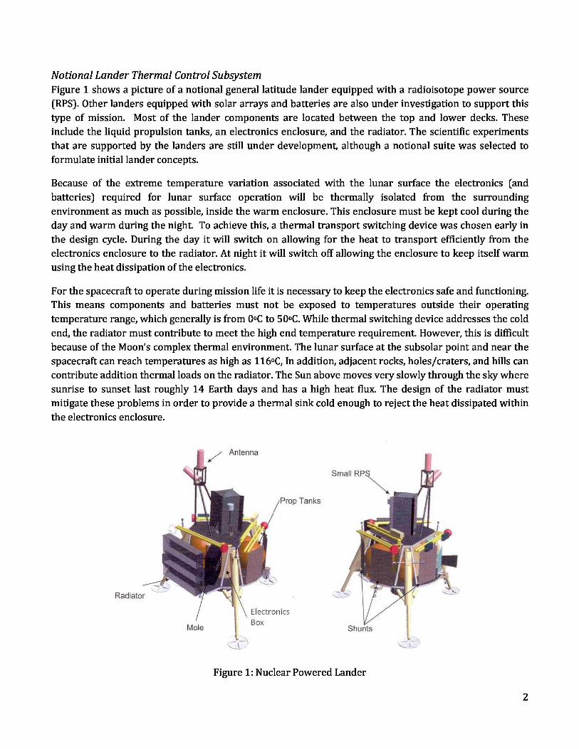
Figure 1 shows a picture of a notional general latitude lander equipped with a radioisotope power source(RPS). Other landers equipped with solar arrays and batteries are also under investigation to support thistype of mission. Most of the lander components are located between the top and lower decks. Theseinclude the liquid propulsion tanks, an electronics enclosure, and the radiator. The scientific experimentsthat are supported by the landers are still under development, although a notional suite was selected toformulate initial lander concepts.
Because of the extreme temperature variation associated with the lunar surface the electronics (andbatteries) required for lunar surface operation will be thermally isolated from the surroundingenvironment as much as possible, inside the warm enclosure. This enclosure must be kept cool during theday and warm during the night. To achieve this, a thermal transport switching device was chosen early inthe design cycle. During the day it will switch on allowing for the heat to transport efficiently from theelectronics enclosure to the radiator. At night it will switch off allowing the enclosure to keep itself warmusing the heat dissipation of the electronics.
For the spacecraft to operate during mission life it is necessary to keep the electronics safe and functioning.This means components and batteries must not be exposed to temperatures outside their operatingtemperature range, which generally is from 0 o C to 50oC. While thermal switching device addresses the coldend, the radiator must contribute to meet the high end temperature requirement. However, this is difficultbecause of the Moon’s complex thermal environment. The lunar surface at the subsolar point and near thespacecraft can reach temperatures as high as 116 oC, In addition, adjacent rocks, holes/craters, and hills cancontribute addition thermal loads on the radiator. The Sun above moves very slowly through the sky wheresunrise to sunset last roughly 14 Earth days and has a high heat flux. The design of the radiator mustmitigate these problems in order to provide a thermal sink cold enough to reject the heat dissipated withinthe electronics enclosure.
Figure 1: Nuclear Powered Lander
2

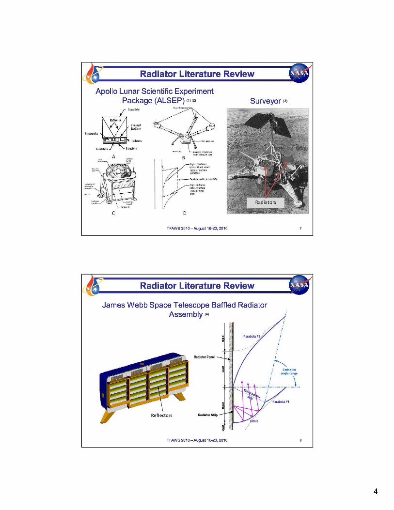
Radiator Literature ReviewThree sources proved to be influential to the radiator study. These were the Apollo Lunar ScientificExperiments Package (ALSEP), Surveyor, and James Webb Space Telescope (JWST). ALSEP was a collectionof scientific experiments that each Apollo mission carried and placed on the Moon. Most of the experimentsperformed for a number of years.(1)(2) Three interestingly designed components were the Main Station,the Lunar Surface Magnetometer (LSM), and the Solar Wind Spectrometer (SWS). All are shown in the leftside of Figure 2. The Main Station contained most of the higher dissipating electronics. Its radiator wasparallel to the lunar surface and had a specular reflective foil in the shape of a V.(3) The LSR and SWS'sradiator consisted of a stack of emissive fins with specular reflective parabolic surfaces. The specularreflective surfaces were used to direct away from the radiator the infrared radiation emitted from the hotlunar surface. Also, both were designed so the heat rejecting surfaces would be shaded from the Sun whenplaced on the ground by astronauts. By limiting the exposure to the high solar flux above and the hot lunarsurface below, this type of design solves two thermal rejection problems associated with a lunar surfacemission.
The Surveyor spacecraft is shown in the right side of Figure 2. These were a series of lunar landers thatpreceded the Apollo landings. They used a mechanical thermal switching device between the electronicsand the radiator. Unfortunately some of the switches failed and most of the landers did not survive throughthe first lunar night.(4) Surveyor used a flat plate radiator that faced skyward and was uncovered. Thisdesign limited the view to the surface, but exposed the radiators to the Sun. By selecting a thermal coatingwith a low solar absorptivity and turning off components during extreme temperatures of lunar noon thelander was able to survive the hot day. The radiator was also aided by partial shadowing provided by thesolar arrays when the sun was directly overhead.
The JWST baffled radiator assembly is shown in Figure 3. This design was inspired by Winston trough typesolar concentrators which were developed in the 1970’s. By using two parabolic reflectors the assemblycontrolled the radiator emission in two directions which was of concern for the JWST project. The design isadvantageous for the lunar surface because, like the ALSEP radiators, the parabolic reflectors can controlwhere the energy that is being reflected onto the radiator is coming from. By having two reflectors, thebaffle design has two acceptance angle ranges which can be tailored for expected hills and tilts.
3

Figure 2: ALSEP (left) and Surveyor Spacecraft (right)
A: Main Station - Side View B: Lunar Surface Magnetometer C: Solar Wind Spectrometer D: ParabolicRadiator - Side View
Figure 3: JWST Radiator: Baffled Assembly (left) and Reflector Side View (right) (5)
4

Paper OutlineThe following section defines the radiator design space. This includes the project parameters and analyticalassumptions. Next, in the thermal modeling section the technique used to analyze the radiators isdescribed. Many preliminary concepts are shown in the Case Study I section. The concepts draw inspirationfrom the previous radiator designs described above. They were analyzed and optimized for the ILNmission. A few of the most promising candidates were then selected and placed in different configurationson the lander thermal model. As described in Case Study II, the configurations were subjected to a set oflanding conditions, and their heat rejection capabilities were calculated. By keeping the set of landingconditions constant, a direct comparison between each configuration could be performed. Two of theconfigurations which best meet the requirements were selected for recommendation.
DESIGN SPACE
Project ParametersA number of parameters for this project are easily defined at this point in the design process. These areshown in Table 1 and include rejection capability, dimensions, and environmental factors among others.Table 2 lists the parameters that are inherently harder to define because there are no exact ways ofknowing what will happen during landing. These parameters were analyzed in two different ways. One wasto define a specific value, say an 8 degree hill, in order to baseline each concept. The other was to analyze arange of values in order to assess the sensitivity of the parameter.
For the hot case design assumptions, the radiator rejection temperature includes a 10 oC knockdown valueassociated with the heat transport system for the expected temperature drop between the electronics boxand the radiator. A lesson learned from Surveyor was there is a large benefit in turning off higherdissipating components during the hottest part of the day. For ILN this will be done by turning thetransmitter off. A preliminary thermal model of the electronics box predicts a 10 Watt heat leak throughthe insulation during the hottest part of the day. The maximum radiator dimensions are determined fromthe space between the upper and lower decks and the legs. The maximum solar flux and surfacetemperature are located on the sub-solar point at the equator.
For the baseline study values, the maximum terrain slope was determined from a statistical analysis of thelunar terrain for the landing sites being considered. Probable rock size was determined from which alander tilt angle was calculated. This value was also used to represent a hole or crater. The maximumAzimuth error, which will skew a north facing radiator to the east or west, was provided by the guidanceand navigation team. There is not a good method for determining the maximum dust coverage, and moreresearch must be done in this area. Dust coverage of 50 and 15 percent were chosen for this study toprovide conservative estimates of deposition while not being so conservative that no radiator conceptcould survive. More information about lunar dust and its effect can be found in the next subsection. Thesensitivity ranges for the terrain and landing error were chosen by taking half of the baseline value thensubtracting and adding it to the baseline value. For sensitivity to dust, many points were taken throughoutthe range.
5

Table 1: Hot Case Design Assumptions and Design Targets
Assumption or Target Value Rationale (if appropriate)
Assumes a 10C delta betweenMaximum Radiator rejection temperature 40 o
C the WEB at 50 and theradiator
Electronics dissipation heat load 66W (transmitter on), notional52W (transmitter off)
Max environmental heat leak also to berejected 10W
Life 6 years
values ranged from .1 to .2, .2Lunar albedo 0.2 chosen to impart max
reflected on radiatornotionally constrained by
Max radiator dimensions 21" (height) x 50" (width) lander dimensions – somegrowth could probably be
entertained
Max solar flux 1414 W/m 2
Maximum lunar surface temperature 116o C
Radiator surface absorptivity/emissivity 0.07/0.8 (OSR) (6)(beginning of life)
Reflector surface absorptivity/emissivity 0.06/0.03 (VDS) (6)( beginning of life)
Table 2: Baseline and Sensitivity Study Values
Baseline Study Sensitivity Study
Max terrain slope 8o 4o, 8o, 12o
Max leg tilt caused by a hill or 6 o 3 o, 6o, 9 o
hole
Max Azimuth error 5 o 2.5 o, 5 o, 7.5 o
Max dust coverage 50% upward facing, 15% 0-100% upward facing, 0-50%downward facing surfaces on downward facing surfaces
Dust AssumptionsTwo basic types of materials were considered for the radiator. The heat rejection surfaces used a low solarabsorptivity, high emissivity material such as an optical surface reflector (OSR). The emission directioncontrolling surfaces used a low absorptivity, low emissivity, and specularly reflective material such asvapor deposited silver (VDS). The top layer of the lunar surface has been described as a fine dust andcaused problems with past surface missions. Two unknowns associated with the regolith are the amountof dust deposition and the effect it will cause on optical properties.
During landing a single thruster will cause the dust to follow a ballistic trajectory away from the lander andhave little chance of being deposited on the spacecraft surfaces. However multiple thrusters may invalidatethis claim. Dust may also be deposited over time while on the Moon. This happens because of chargingassociated with the Sun during the day and plasma currents at night.
Gaier has published results pertaining to the change in the absorptivity and emissivity to percent dustcoverage.(7) The paper focuses on common radiator materials with high emissivity and low absorptivityproperties, such as white thermal control paint (AZ93) and a second surface mirror (Ag coatedFEP/Teflon). Also the paper assumes a monolayer of dust. Using his results and assuming that for a highemissivity surface the addition of lunar dust, which also has a high emissivity, does not affect theemissivity. The following equation was developed to determine the change in absorptivity.
Where d is the amount of dust coverage in percentage and αBOL is the beginning of life solar absorptivity.The final equation used to determine the solar absorptivity for the radiator surface included factors fordust and time.
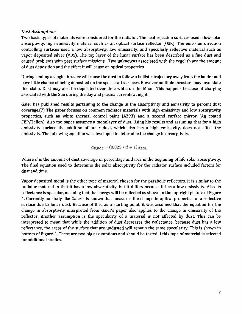
Vapor deposited metal is the other type of material chosen for the parabolic reflectors. It is similar to theradiator material in that it has a low absorptivity, but it differs because it has a low emissivity. Also itsreflectance is specular, meaning that the energy will be reflected as shown in the top-right picture of Figure4. Currently no study like Gaier's is known that measures the change in optical properties of a reflectivesurface due to lunar dust. Because of this, as a starting point, it was assumed that the equation for thechange in absorptivity interpreted from Gaier’s paper also applies to the change in emissivity of thereflector. Another assumption is the specularity of a material is not affected by dust. This can beinterpreted to mean that while the addition of dust decreases the reflectance, because dust has a lowreflectance, the areas of the surface that are undusted will remain the same specularity. This is shown inbottom of Figure 4. These are two big assumptions and should be tested if this type of material is selectedfor additional studies.
7
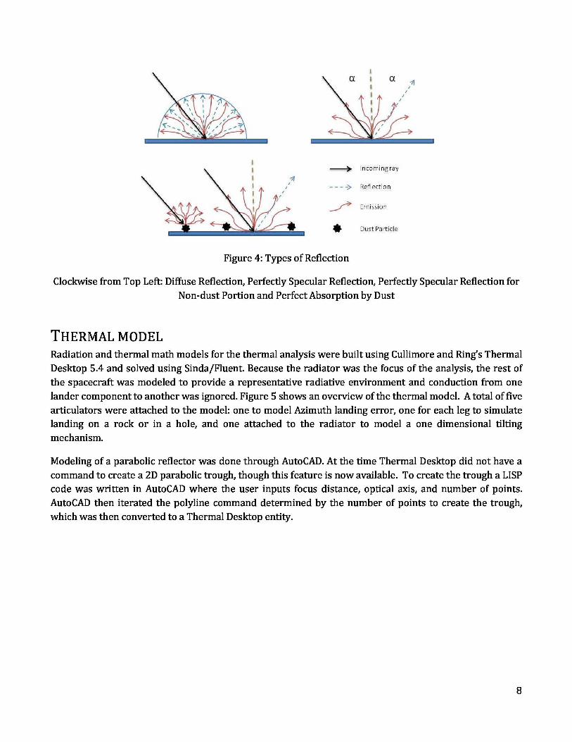
Figure 4: Types of Reflection
Clockwise from Top Left: Diffuse Reflection, Perfectly Specular Reflection, Perfectly Specular Reflection forNon-dust Portion and Perfect Absorption by Dust
THERMAL MODELRadiation and thermal math models for the thermal analysis were built using Cullimore and Ring’s ThermalDesktop 5.4 and solved using Sinda/Fluent. Because the radiator was the focus of the analysis, the rest ofthe spacecraft was modeled to provide a representative radiative environment and conduction from onelander component to another was ignored. Figure 5 shows an overview of the thermal model. A total of fivearticulators were attached to the model: one to model Azimuth landing error, one for each leg to simulatelanding on a rock or in a hole, and one attached to the radiator to model a one dimensional tiltingmechanism.
Modeling of a parabolic reflector was done through AutoCAD. At the time Thermal Desktop did not have acommand to create a 2D parabolic trough, though this feature is now available. To create the trough a LISPcode was written in AutoCAD where the user inputs focus distance, optical axis, and number of points.AutoCAD then iterated the polyline command determined by the number of points to create the trough,which was then converted to a Thermal Desktop entity.
8

Figure 5: Lander Thermal Model Nomenclature (as landed in the northern hemisphere)
Environmental ModelingThe environment was modeled using the Thermal Desktop Orbit command. With this command the userdefines the solar vector, solar flux, planet vector and distance, planet temperature, and albedo. ThermalDesktop uses a ray tracing algorithm to calculate the environmental flux for each surface and then applies itas a boundary condition. Defining a negligible planet distance results in the planetary surface beingmodeled as infinitely large, flat, and isothermal. This is a disadvantage because it does not take into accountshadows cast by the lander. Another way of modeling the surface is to use Thermal Desktop surfaces.However, to calculate the albedo correctly would require many nodes and a large amount of rays, whichwould increase the run time. Using the worst case tilt of the radiator to the surface, a comparison study wasdone between the two methods of modeling. It was found that shadows did not affect the radiatorperformance. However, it does affect the lander structure temperature, and therefore a system model ofthe lander should use Thermal Desktop surfaces to model the surface ground plane.
Another disadvantage of the Orbit command is its lack of ability to model a hill. This was overcome withinthe Orbit menu by defining the planet vector corresponding to the hill slope. Three different landingscenarios are shown in Figure 6. The top left models the spacecraft as nominally landed on a flat surfacewith no hills. The top right is landed next to a hill. This is a conservative model because the hill is infinitelylong. Finally the bottom picture is landed on a hill. Articulators were used to model a leg landed on a rockor in a hole.
9
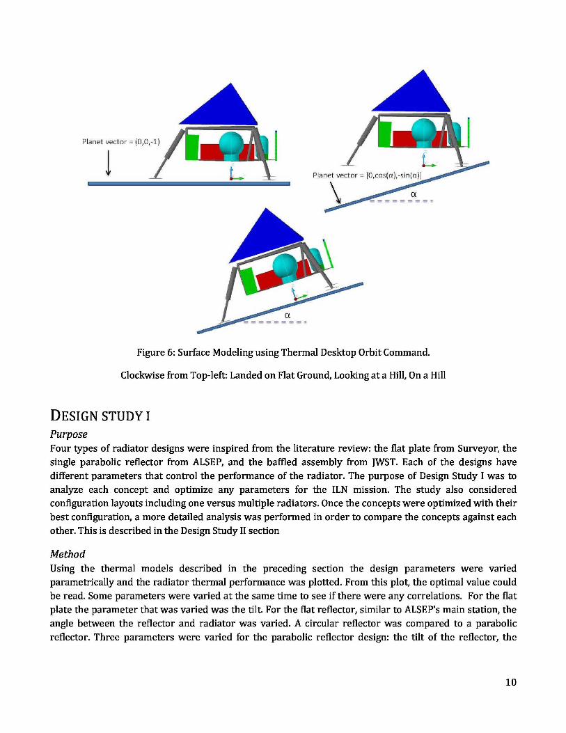
Figure 6: Surface Modeling using Thermal Desktop Orbit Command.
Clockwise from Top-left: Landed on Flat Ground, Looking at a Hill, On a Hill
DESIGN STUDY I
PurposeFour types of radiator designs were inspired from the literature review: the flat plate from Surveyor, thesingle parabolic reflector from ALSEP, and the baffled assembly from JWST. Each of the designs havedifferent parameters that control the performance of the radiator. The purpose of Design Study I was toanalyze each concept and optimize any parameters for the ILN mission. The study also consideredconfiguration layouts including one versus multiple radiators. Once the concepts were optimized with theirbest configuration, a more detailed analysis was performed in order to compare the concepts against eachother. This is described in the Design Study II section
MethodUsing the thermal models described in the preceding section the design parameters were variedparametrically and the radiator thermal performance was plotted. From this plot, the optimal value couldbe read. Some parameters were varied at the same time to see if there were any correlations. For the flatplate the parameter that was varied was the tilt. For the flat reflector, similar to ALSEP’s main station, theangle between the reflector and radiator was varied. A circular reflector was compared to a parabolicreflector. Three parameters were varied for the parabolic reflector design: the tilt of the reflector, the
10

length of the reflector, and the tilt of the radiator. The baffled assembly adds another two variables whichare the tilt and length of the additional reflector.
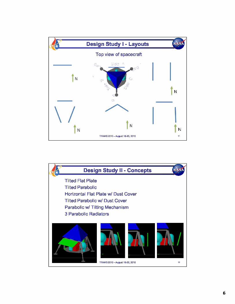
Configuration layouts were analyzed for the parabolic designs. Because the parabolic design is vertical, thisallowed for configurations with multiple radiators. The radiators could be located on different sides of thespacecraft viewing different directions. The multiple radiator analysis assumed that when a radiatorproduced negative rejection, the heat transport system would turn off conduction to that radiator.
ResultsSome of the designs and the parameters that were varied are shown in Table 3 while the differentconfigurations are shown in Table 4. For the flat plate, varying the tilt reduced the solar load into theradiator but increased the input from the surface. The heat rejection versus tilt plot was not linear andthere was an optimal tilt angle. This angle is a function of latitude and the assumed solar absorptivity andemissivity. Three reflector designs were analyzed: flat, circular, and parabolic. Out of the three theparabolic performed the best. Tilting the optical axis and/or the radiator of the parabolic design did notprovide much benefit. The baffled assembly is highly sensitive to the lunar environment. Because of thenature of the design any hills, tilts, or landing errors that caused the radiator to view the surface or the sundramatically reduced its performance.
Different stacked radiator configurations are shown in Table 4. Usually changing the configuration woulddiminish the sensitivity to one type of off-nominal landing while increasing the sensitive in another. Evenwith multiple radiators, there was always a landing scenario that would substantially diminish the totalrejection.
Based on the results of the Design Study I, the following concepts were recommended: tilted flat plate,tilted parabolic, horizontal flat plate with a dust cover, vertical parabolic with a dust cover, verticalparabolic with a tilting mechanism, and three parabolic radiator in the fourth configuration of Table 4.These concepts will be described in greater detail in the next section.
11

Table 3: Radiator Designs
Description Picture Comments
Design recommended, sensitive to dust because of viewHorizontal radiator to sun, low sensitivity to landing errors and lunar
surface
The greater the tilt angle the less inputfrom the sunTilted radiator (therefore less sensitivity to dust), however it increases
heat input from the lunar surface
Horizontal radiator Similarto ALSEP main station, no direct view to the sun,
with a flat reflector
isome heatfrom the lunar surface will be reflected onto
A2 i
the radiator
Tilted radiator with aflat reflector Increases heat input from the lunar surface
Horizontal radiator Reflects lunar heat awayfrom radiator, parabolicwith a circular reflector has as a tighter focusreflector
Horizontal radiator Design recommended , insensitive to dust because nowith a parabolic view to sun, no heat reflected onto radiator (nominalreflector
Y. Y/
landing), highly sensitive to landing errors
Horizontal radiator Optical axis can be tilted so as when the assembly isand a parabolic tilted towards the surface the lunar heat will not bereflector with a tilted^
reflected onto the radiator, sensitive to tilts towards theoptical axis sun
Titled radiator and a-
When the assembly is tilted towards the surface thelied , '. lunarheat will not be reflected onto the radiator,opticalwith
aa tilted optical
with
sensitiveto tilts towards the sunaxis ,^ ..^"
I
Baffles designed so that the radiator will not receive
Baffled radiator heatwhen either tilted towards the surface or sun.Requires significant more area, and extremely sensitive
to seeing the sun or surface
12
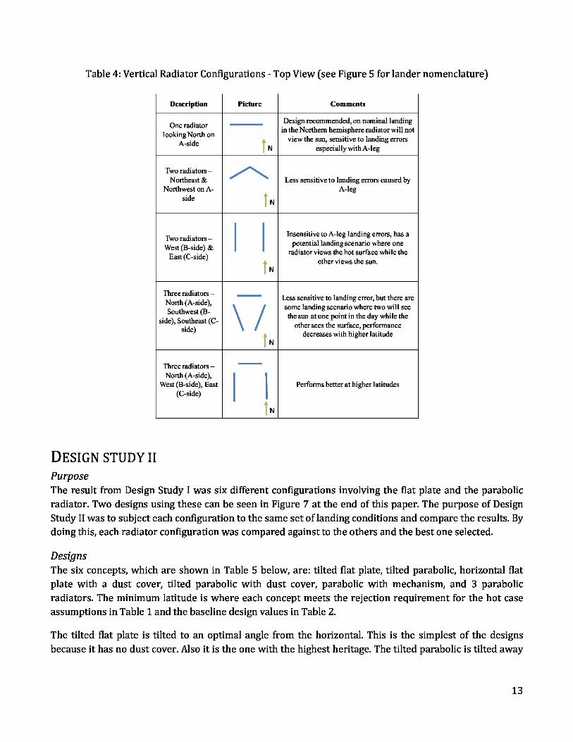
Table 4: Vertical Radiator Configurations - Top View (see Figure 5 for lander nomenclature)
Description Picture Comments
One radiatorDesign recommended, on nominal landing
looking North onin the Northern hemisphere radiator will not
A-sideview the sun, sensitive to landing errors
N especially with A-leg
Two radiators –Northeast & Less sensitive to landing errors caused by
Northwest on A- A-legside
N
Two radiators –Insensitive to A-leg landing errors, has a
West (B-side) &potential landing scenario where one
East (C-side)radiator views the hot surface while the
other views the sun.N
Three radiators –Less sensitive to landing error, but there are
North (A-side),some landing scenario where two will see
Southwest (B- ` /the sun atone point in the day while the
side), Southeast (C-other sees the surface, performance
side)decreases with higher latitude
N
Three radiators –North (A-side),
West (B-side), East Performs better at higher latitudes(C-side)
N
DESIGN STUDY II
PurposeThe result from Design Study I was six different configurations involving the flat plate and the parabolicradiator. Two designs using these can be seen in Figure 7 at the end of this paper. The purpose of DesignStudy II was to subject each configuration to the same set of landing conditions and compare the results. Bydoing this, each radiator configuration was compared against to the others and the best one selected.
DesignsThe six concepts, which are shown in Table 5 below, are: tilted flat plate, tilted parabolic, horizontal flatplate with a dust cover, tilted parabolic with dust cover, parabolic with mechanism, and 3 parabolicradiators. The minimum latitude is where each concept meets the rejection requirement for the hot caseassumptions in Table 1 and the baseline design values in Table 2.
The tilted flat plate is tilted to an optimal angle from the horizontal. This is the simplest of the designsbecause it has no dust cover. Also it is the one with the highest heritage. The tilted parabolic is tilted away
13

from the surface to an optimal angle. This is the simplest of the parabolic designs because it contains nodust cover or mechanism.
The next two concepts are the horizontal flat plate and tilted parabolic with a dust cover. The rationale forusing a dust cover follows from the assumption that the highest probability of dust deposition is duringlanding. The dust cover would cover the radiator during landing after which a simple mechanism wouldrelease the cover. A radiator with a dust cover was assumed to have 15% dust coverage on upward facingand 5% on downward facing surfaces, as opposed to 50% and 15% for without a dust cover. Theseconcepts are a bit more complex and extra heater power might be required during flight to keep the releasemechanism from freezing. Also there is a potential mass penalty associated with extra covers ormechanisms.
During the Design Study I it was found that the parabolic design was sensitive to off-nominal landings,which could cause the radiator to view either the surface or the Sun. This motivated the use of a onedimensional tilting mechanism to counteract the off-nominal landings. It would be activated one time afterlanding and would tilt the radiator either towards or away from the surface. A three dimensionalmechanism was also analyzed, but controlling the other two dimension did not have enough reward tojustify the associated complexity.
The three parabolic radiator configuration consists of three vertical parabolic radiators placed in the north,southeast, and southwest orientation. This is shown as the forth configuration in Table 4. The configurationis more complex because the heat transport system would have to run to all three and be able to switch offindividual radiators when they produced negative rejection.
Table 5: Six Concepts
Tilted Flat Tilted Horizontal Flat Plate Tilted Parabolic w/ Parabolic w/ 3 ParabolicPlate Parabolic w/ Dust Cover Dust Cover Mechanism Radiators
Minimum 22° 9° Equator Equator Equator EquatorLatitude
Complexity Simple Reflectors, Cover Reflectors, fins, Reflectors, fins, Reflectors, finsfins cover mechanism plumbing, control
Heritage HighLimited(ALSEP) High Limited (ALSEP) Limited Limited
Additional Heater power for Heater power for Heater power for Increase transportComments mechanism mechanism mechanism mass
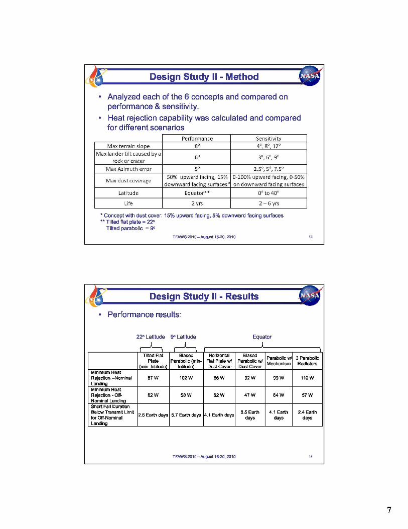
MethodDesign Study II compared the radiators on a number of criteria. Using the hot case assumptions in Table 1and the baseline design values in Table 2 each concept performance was calculated for nominal and off-nominal landings. The off-nominal landing used the baseline values from Table 2: 8 o hill, 6o rock or hole,
14

and 5 o Azimuth error. The duration of time a concept’s performance fell below the heat rejection requiredduring transmitter operation was also calculated.
The sensitivity of each concept was measured using the range of values in Table 2. Also the sensitivity tolatitude and life time was calculated. The method for measuring sensitivity was to calculate and plot theperformance at each value for both nominal and off-nominal landing. By comparing the plots between theconcepts a scale from one to five was assigned where a value of one demonstrates either low sensitivity tothe parameter or meeting the requirement, and a value of five signifies either high sensitivity or failing therequirement.
ResultsThe concept performance is shown in Table 6 below. On nominal landing, the flat plate does not exhibitheat reject capability as high as that exhibited by the parabolic design. However the flat plate is a lot lesssensitive to off-nominal landing than the parabolic, because the parabolic will collect and focus the energyif it views the Sun or surface. This affect can be alleviated somewhat by using a tilting mechanism. Thethree parabolic radiators had the shortest amount of time for turning the transmitter off, but had thegreatest drop in rejection between nominal and off-nominal landing.
Table 6: Concept Performance
Tilted Flat Plate Biased ParabolicHorizontal
Biased Parabolic Parabolic w/ 3 Parabolic(min latitude) (min-latitude)
Flat Plate w/ Dustw/ Dust Cover Mechanism Radiators
Cover
Minimum Heat Rejection --Nominal Landing
87 W 102 W 66 W 92 W 99 W 110 W
Minimum Heat Rejection -Off-Nominal Landing
62 W 58 W 62 W 47 W 64 W 57 W
Short Fall Duration BelowTransmit Limit for Off- 2.5 Earth days 5.7 Earth days 4.1 Earth days 6.5 Earth days 4.1 Earth days 2.4 Earth daysNominal Landing
The concept sensitivities are shown in Table 7. There is a lot that can be drawn from the table so some ofthe key points will be discussed here. The flat plate in general is a lot less sensitive to off-nominal landingerrors that would increase the view to the surface. This is especially true for the horizontal flat plate. Thetilted flat plate received a higher sensitivity in latitude because it could not meet requirements below 22 o
latitude. The performance of the horizontal flat plate increased quickly with latitude. The flat plate isextremely sensitive to dust and life because these two factors increase the solar absorptivity and the plateis directly exposed to the Sun. If it is reasoned that the highest probability for dust deposition is duringlanding, this sensitivity motivates the use of a dust cover.
The parabolic radiators are very sensitive to off-nominal landing errors, except for Azimuth errors. Thethree radiator design was very sensitive to latitude because both the southeast and southwest radiatorsbecome exposed to the Sun with latitude. Because of this, the concept is only feasible at the equator. Theuse of a mechanism helps alleviate the sensitivity to rocks and holes/craters but does little for hills. This isbecause at the equator, pointing away from a hill exposes the radiator to the Sun. This effect will lessen
15

with latitude. The biased parabolic is sensitive to dust and lifetime because its potential sun exposure isincreased .
Table 7: Concept Sensitivities (1 - low sensitivity and/or meets requirements 5 - high sensitivity and/orfails requirements)
Tilted Flat Plate Biased Parabolic Horizontal Biased Parabolic w/ Parabolic w/ 3 Parabolic(min_latitude) (min-latitude) Flat Plate w/ Dust Cover Dust Cover Mechanism Radiators
Sensitivity to4 3 1 3 2 5
Latitude
Sensitivity to Hills 4 5 1 5 4 4
Sensitivity to 2 4 1 4 2 4Rocks and Holes
Sensitivity to 1 1 1 1 2 2Azimuth Errors
5(cover would mitigateSensitivity to Dust 5 2
this sensitivity)3 1 2
Sensitivity to5 3 5 4 2 2
Lifetime
Concept RecommendationBased on the results in Design Study II the horizontal flat plate with a dust cover and the parabolic with atilting mechanism were recommended to the project. Both of these concepts are shown in Figure 7. The flatplate is recommended because of its low sensitivity to off-nominal landing scenarios. However, it issensitive to dust and life. For dust the amount of deposition will always be an unknown, but with theaddition of a dust cover or other repelling devices the amount of deposition can be reduced. The sensitivityto life is better understood and accounted for by oversizing the radiator.
The parabolic radiator has a higher performance on nominal landing than the flat plate, and it is also lesssensitive to dust and life. However it is much more sensitive to off-nominal landing scenarios. The use of atilting mechanism helps alleviate this but does little for hills at the equator. Another difference between thetwo is that the parabolic design is vertical while the flat plate is horizontal. Depending on the spacecraftdesign, one orientation could be more beneficial.
16
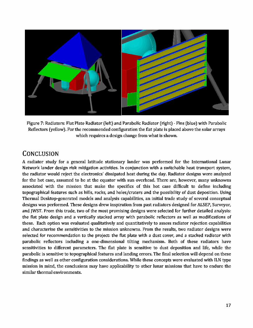
Figure 7: Radiators: Flat Plate Radiator (left) and Parabolic Radiator (right) - Fins (blue) with ParabolicReflectors (yellow). For the recommended configuration the flat plate is placed above the solar arrays
which requires a design change from what is shown.
CONCLUSIONA radiator study for a general latitude stationary lander was performed for the International LunarNetwork lander design risk mitigation activities. In conjunction with a switchable heat transport system,the radiator would reject the electronics' dissipated heat during the day. Radiator designs were analyzedfor the hot case, assumed to be at the equator with sun overhead. There are, however, many unknownsassociated with the mission that make the specifics of this hot case difficult to define includingtopographical features such as hills, rocks, and holes/craters and the possibility of dust deposition. UsingThermal Desktop-generated models and analysis capabilities, an initial trade study of several conceptualdesigns was performed. These designs drew inspiration from past radiators designed for ALSEP, Surveyor,and JWST. From this trade, two of the most promising designs were selected for further detailed analysis:the flat plate design and a vertically stacked array with parabolic reflectors as well as modifications ofthese. Each option was evaluated qualitatively and quantitatively to assess radiator rejection capabilitiesand characterize the sensitivities to the mission unknowns. From the results, two radiator designs wereselected for recommendation to the project: the flat plate with a dust cover, and a stacked radiator withparabolic reflectors including a one-dimensional tilting mechanism. Both of these radiators havesensitivities to different parameters. The flat plate is sensitive to dust deposition and life, while theparabolic is sensitive to topographical features and landing errors. The final selection will depend on thesefindings as well as other configuration considerations. While these concepts were evaluated with ILN typemission in mind, the conclusions may have applicability to other lunar missions that have to endure thesimilar thermal environments.
17

ACKNOWLEDGEMENTSThe authors would like to extend appreciation to Jeff Farmer of MSFC, the thermal lead for the ILN project.He provided a great deal of guidance and feedback during this study.
ACRONYMSALSEP – Apollo Lunar Scientific Experiment Package
APL – Applied Physics Laboratory
ASRG – Advanced Stirling Radioisotope Generator
ILN – International Lunar Network
JWST – James Webb Space Telescope
LSM – Lunar Surface Magnetometer
MSFC – Marshall Space Flight Center
OSR – Optical Surface Reflector
RPS - Radioisotope Power Source
SWS – Solar Wind Spectrometer
VDS – Vapor Deposited Silver
REFERENCES1.Collicott, H.E. and McNaughton, J.L. Thermal Control in a Lunar Envrionment. s.l. : Bendix Tech. Journal,1970.
2. Bates, James R, Lauderdale, W.W. and Kernaghan, Harold. ALSEP Termination Report. 1979. NASAReference Publication 1036.
3. Robert S. Harris, Jr., MSC. Apollo Experience Report Thermal Design of Apollo Lunar Surface ExperimentsPackage. 1972. NASA TN D-6738.
4.Vickers, J. M. F. and Garipay, R. R. Thermal Design Evolution and Performance of the Surveyor Spacecraft.Philadelphia : AIAA, 1968. No. 68-1029.
5.Perrygo, Charles and Garrison, Matthew. Directional Baffles for Lateral Control of Radiator EmissionDirection. s.l. : Thermal Fluid Analysis Work Shop (TFAWS), 2006.
6. Gilmore, David. Spacecraft thermal Control Handbook. [book auth.] W. K. Stuckey, M. Fong D. G. Gilmore.Thermal Surface Finishes. s.l. : The Aerospace Corporation, 2002.
18

7. Gaier, James R. Effect of Illumination Angle on the Performance of Dusted Thermal Control Surfaces in aSimulated Lunar Environment. s.l. : ICES, 2009. 09ICES-0279.
CONTACTBrian O'Connor
Mail Code ES22
NASA Marshall Space Flight Center
MSFC, AL 35812
Phone: (256) 544-6649
Email: [email protected]
Elisabeth Abel
Johns Hopkins University
Applied Physics Laboratory
11100 Johns Hopkins Road
Laurel, MD 20723-6099
Phone: (240) 228-7704
Email: [email protected]
19

Radiator Study for StationaryLunar Landers
Brian O’Connor
(NASA/Marshal Space Flight Center)
Elisabeth Abel(Johns Hopkins University Applied Physics
Laboratory)
Thermal & Fluids Analysis Workshop
•^' TFAWS 2010
^ sc *2- :0Q 1 0 August 16-20, 2010Houston, TX 201_
• ILN Project Overview
• Thermal System
• Design Space
• Literature Review
• Thermal Model
• Case Study I
• Case Study II
• Conclusion
TFAWS 2010—August 16-20, 2010 2
1
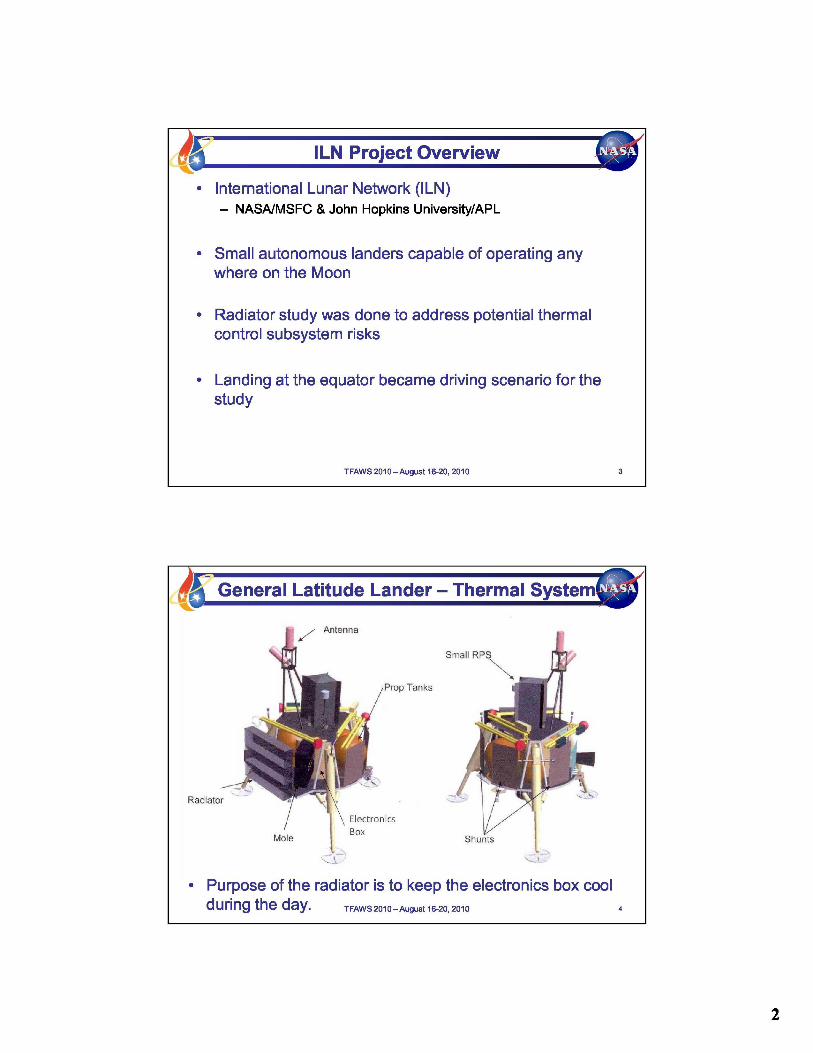
• International Lunar Network (ILN)— NASA/MSFC & John Hopkins University/APL
• Small autonomous landers capable of operating anywhere on the Moon
• Radiator study was done to address potential thermalcontrol subsystem risks
• Landing at the equator became driving scenario for thestudy
TFAWS2010-August 16-20, 2010
• Purpose of the radiator is to keep the electronics box coolduring the day. TFAWS 2010 - August 16-20, 2010 4
2

Radiator rejection temperature 40 °C
Rejection amount 66 Watt (transmitter on)52 Watt (transmitter off)
Max environmental heat leak also to berejected 10W
Minimum life 2yearsLunar albedo 0.2
Max radiator dimensions 21" (height) x 50" (width)
Max solar flux 1414 W/mZMaximum lunar surface temperature 116°C
TFAWS2010—August 16-20, 2010
James Webb Space Telesco pe Baffled RadiatorAssem
TFAWS2010—August 16-20, 2010
Radiator Literature Review
Apollo Lunar Scientific ExperimentPackage (ALSEP) mm
Surveyor (3)
TFAWS2010—August 16-20, 2010
4

Flat Plate (Surveyor) V-radiator (ALSEP's Main Station)
Parabolic Radiator (ALSEP's SWS) Baffled Radiator (JWST)
TFAWS2010—August 16-20, 2010
Design Study I - Layouts
Top view of spacecraft
MAR:
A
JIL
071
q rN,
ChN!
TFAWS 2010 — August 16-20, 2010
Design Study 11 - Concepts SoTilted Flat PlateTilted ParabolicHorizontal Flat Plate w/ Dust CoverTilted Parabolic w/ Dust CoverParabolic w/ Tilting Mechanism
3 Parabolic Radiators
04
TFAWS 2010 —August 16-20,2010 12
6
' Design Study II - Method
• Analyzed each of the 6 concepts and compared onperformance & sensitivity.
• Heat rejection capability was calculated and comparedfor different scenarios
Performance Sensitivity^Maxter,rainslope ^, 8° 4°, 8°, 1Z°
^Max;landertiltc"ausedW, 176231nrock M7rater,
nMaxAzimuth error, 5° 2.5°, 5°, 7.5°^
^^nMax dust coverage 50%Dpward,fa ingJ 15%_
t^down,w_ard faEn,gfsurfacesr0-100% upward facing, 0..50%n_rnidow,n,ward facing+fso,face" )
Latitude Equate * 0° IZ 4(
L'Life R yrs R -'- 6 yrs
J
* Concept with dust cover: 15% upward facing, 5% downward facing surfaces** Tilted flat plate = 220
Tilted parabolic = 90TFAWS2010—August 16-20, 2010 13
• Performance results:
220 Latitude 90 Latitude EquatorA
Tilted Flat Biased Horizontal BiasedParabolic w/ 3 Parabolic
Plate Parabolic (min- Flat Plate w/ Parabolic w/ Mechanism Radiatorsmin latitude latitude) Dust Cover Dust Cover
Minimum HeatRejection -Nominal 87 W 102 W 66 W 92 W 99 W 110WLandingMinimum HeatRejection - Off- 62 W 58W 62 W 47W 64 W 57 WNominal LandingShort Fall DurationBelow Transmit Limit
2.5 Earth days 5.7 Earth days 4.1 Earth days6.5 Earth 4.1 Earth 2.4 Earth
for Off-Nominal days days daysLanding
TFAWS2010—August 16-20, 2010

• General observations:— Nominal landing — parabolic design outperforms the flat plate— Off nominal landing — parabolic is much more sensitive— Flat plate is sensitive to dust and life— Parabolic is sensitive to hills and tilts
• Design study recommended concepts:1) Horizontal flat plate w/ dust cover2) Parabolic w/ tilting mechanism
TFAWS2010—August 16-20, 2010 15
i Conclusion
• Radiator study completed for the ILN mission:— Small, autonomous, general latitude lander
• Literature review resulted in four types of designs• Designs were optimized for mission — six concepts
resulted• Six concepts were analyzed for performance and
sensitivities• Two concepts were chosen for recommendation
TFAWS2010—August 16-20, 2010 16
8

1. Bates, James R; Lauderdale, WW; and Kernaghan, Harold. ALSEPTermination Report. 1979. NASA Reference Publication 1036.
2. Robert, S. Harris, Jr.; MSC. Apollo Experience Report ThermalDesign of Apollo Lunar Surface Experiments Package. 1972.NASA TN D-6738
3. Vicker, J. M. F and Garipay, R.R. Thermal Design Evolution andPerformance of the Surveyor Spacecraft. Philadelphia: AIAA, 1968.No. 68-1029.
4. Perrygo, Charles and Garrison, Matthew. Directional Baffles forLateral Control of Radiator Emission Direction. TFAWS, 2006.
5. Gaier, James R. Effect of Illumination Angle on the Performance ofDusted Thermal Control Surfaces in a Simulated LunarEnvironment. ICES, 2009. 0910ES-0279
TFAWS2010—August 16-20, 2010 17
BACKUP SLIDES
TFAWS2010—August 16-20, 2010 18
9

• Two types of materials considered:1) Low absorptivity, high emissivity for radiative surfaces2) Low absorptivity, low emissivity, and specular for reflective
surfaces
• James Gaier has studied the effects of lunar dustsimulant on common radiative materials (5)
• Based on his results, a dust knock-up equation wasdeveloped for change in absorptivity
• Other assumptions:— The dust does not affect the emissivity of a radiative surface— The dust equation applies to both absorptivity and emissivity for
the reflective surfaces— Dust does not change the specularity of a reflective material, it
only changes the amount of reflectance.
TFAWS2010—August 16-20, 2010 19
Modeling Hills
M
Planet vector = Igcos(a^n(aj] _ ^ ^ ^^ ^ ^^
1 TFAWS2010—August 16-20, 2010 20
10