radiation shielding at high-energy electron and proton ... · pdf fileradiation shielding at...
TRANSCRIPT
Work supported in part by US Department of Energy contract DE-AC02-76SF00515
FERMILAB-PUB-07-608-ESH Submitted to: Proceedings of the Health Physics Society 2008 Professional Development School - Topics in
Accelerator Health Physics (Oakland CA, January 2008)
Radiation Shielding at High-Energy Electron and Proton Accelerators
Sayed H. Rokni1, J. Donald Cossairt
2, James C. Liu
1
Introduction
The goal of accelerator shielding design is to protect the workers, general public, and the
environment against unnecessary prompt radiation from accelerator operations. Additionally,
shielding at accelerators may also be used to reduce the unwanted background in experimental
detectors, to protect equipment against radiation damage, and to protect workers from potential
exposure to the induced radioactivity in the machine components. The shielding design for
prompt radiation hazards is the main subject of this chapter.
General Considerations in the Shielding of Accelerators
High-energy accelerators are capable of producing radiation fields of high energy and
high intensity, mixed with photons and neutrons. Protection against these radiation fields can be
effectively achieved by attenuating the radiation to acceptable levels with appropriate thickness
and proper types of shield materials, which can be placed either locally or as structure housing.
In addition to the shielding itself, the degree to which the radiation level must be
attenuated depends on several factors, such as: 1) the radiation source terms, 2) the distance from
the radiation source to the dose point of interest, 3) the conservative estimate of the time that the
workers or public may spend at the dose point (or the irradiation time for the object to be
protected), and 4) the required dose limits outside the shield.
1Stanford Linear Accelerator Center (SLAC), Stanford, CA, 94205
2Fermi National Accelerator Laboratory, Batavia, IL 60510
SLAC-PUB-13033December 2007
2
The radiation source terms and the applicable dose limits (derived from regulations
and/or facility’s administrative limits) provide starting points for determining shielding
requirements. The radiation source terms depend on accelerator beam parameters (the type of
beam particle and its energy and intensity) and accelerator operation modes, which in general are
provided by accelerator or facility physicists. Various modes of accelerator operation (e.g.,
normal beam losses and abnormal beam losses under credible scenarios), as well as appropriate
dose limits for different scenarios, need to be carefully considered in the shield design process.
In general, normal beam losses occur at specific beamline locations, such as beam
absorbers or “dump” (or beam stop), collimators, beam scrapers, or other beam-defining
apertures, while abnormal beam losses are assumed to occur at any point, except for locations
that can specifically excluded by design. The normal-beam-loss points can then be locally
shielded and the rest of the machine can be more lightly shielded. Detailed knowledge and close
control of the beam operation modes and locations of beam losses, as well as alignment of these
critical beam-defining devices, are necessary to ensure these important estimation and
assumption used in shielding design. Exclusion of beam losses at specific locations by
engineered design should verified by independent review by qualified experts and by
measurement, if the latter is feasible.
Since accelerator’s maximum capability may exceed its desired operating level (in energy
or intensity) any potential facility upgrade should also be considered at the time of initial design
to avoid the burden of major shielding modification or operation limitation in the future.
Consideration of cost and/or space could prohibit shielding for full capability of an
accelerator, or for full beam losses at all locations. Therefore, in most large accelerators, a
balanced combination of passive system (shielding and fence) and active systems (limiters and
3
detectors) can offer a cost-effective solution to meet both the safety and operational
requirements. For example, active current monitors can be used to monitor and limit the beam
current that is allowed to enter a beamline. Radiation monitors could also be placed inside and/or
outside of the shielding wall to detect and terminate unexpected, high radiation levels. In general,
the use of passive systems is preferred as the use of active systems may not provide the inherent
reliability of adequate shields. The use of active system to complement the passive systems must
be carefully analyzed to see if the proper degree of safety will be achieved. A complete
discussion of use of active systems to augment shielding is provided in Liu, et al. (2007).
In summary, accelerator shielding design should consider the followings:
• The parameters to be considered include the maximum beam energy and intensity,
average beam power, normal and abnormal beam losses, schedule and modes of
operations, area classification and area occupancy.
• Shielding should be designed for maximum normal operation with allowance for
occasional high beam losses.
• The maximum capability of the accelerator should be considered for targets and dumps.
• In addition to an annual dose limit for normal beam losses, a maximum dose rate limit
should be established for high, but occasional, beam losses. Dose limits for radiation
workers and the members of public should be considered.
• Environmental radiological impact from beam operations (activation of air, soil and
groundwater) should be considered.
• The shielding design should be an integral part of the overall safety design of the
accelerator.
4
The following checklist is recommended by Schopper et al. (1990) in arriving at a shielding
specification:
• Assess the physical lay-out
• Subdivide the facility according to functional and constructional requirements
• Define the primary and secondary radiation sources and the source strengths for
normal permanent operation, occasional special operations and unwanted excursions.
• Specify an overall safety factor in the source definition which must include possible
future use and operations.
• Define the maximum dose/year and the maximum dose rates in areas outside the
projected shielding.
• Specify the attenuation needed for all sources and areas.
• Estimate the shielding
• Define a tentative shielding layout.
• Assess the overall attenuation obtained and check for conflicting interests before
proceeding with the design of the final layout.
Monte Carlo codes, such as FLUKA (Fasso 2005), MARS15 (Mokhov 1995), EGS4
(Nelson et al. 1985), MCNPX (McKinney 2007), or PHITS (Iwase 2002) provide the most
accurate results for shielding design, in particular for complicated three-dimensional geometries.
However, much time and effort can be saved by use of analytic methods that are widely used for
solution of practical shielding problems.
In the next two sections of this chapter, the radiation source terms in high-energy electron
and proton accelerators and their shielding by common shielding materials such as lead, concrete
5
and polyethylene using analytical and semi-empirical methods are described for high-energy
electron and proton accelerators (defined as accelerators with beam energy more than 10 MeV).
The underlying physical process for radiation source terms and common methods and tools for
calculating shielding requirements are discussed.
Shielding of Electron Accelerators
For a high-energy electron accelerator, the underlying process involved in the production
of the various prompt radiation fields is the electromagnetic (EM) cascade shower that is
developed in the interactions of high energy electrons with matter, beam device or target. Only a
small fraction of the energy is dissipated as a result of collision processes, such as ionization and
excitation, while a large fraction is spent in the production of high energy photons
(bremsstrahlung). The secondary photons, in turn, undergo materialization into electron positron
pairs or make Compton collisions. These process results in the electrons having energies
comparable to the photons, and the process continues until more and more electrons fall into the
energy range where radiation losses no longer can compete with collision losses. Eventually the
energy of the initiating particle is completely dissipated in excitation and ionization of atoms.
The electron energy at which the average energy loss due to radiation and due to
ionization are equal is know as Critical Energy, CE . The value of CE in MeV is approximately
given by
2.1
800
+=
ZEC (1)
where Z is the atomic number of the target materials (Rossi, 1952). For electron energies
above CE , radiation losses become increasing dominant. The approximate scale length that
describes the high-energy propagation of EM cascade is called, the radiation length, X0. It is the
6
mean thickness of materials over which the energy of an electron is reduced by a factor of e .At
energies higher than CE (where ionization may be neglected) the energy E of an electron at
depth X is given by
0X0/
0
XeEE
−= (2)
The radial shower distribution is usually described in terms of Molière radius Xm:
c
s
mE
EXX 0= (3)
where ES = 21.2 MeV
A more detailed discussion of source components of the prompt radiation fields is given
in (Vylet 2007; Vylet et al. 2001). The following conclusions generally apply to high-energy
electron accelerators:
• Photons and giant resonance neutrons (GRN) dominate the radiation field inside
shielding enclosures and remain a significant component behind moderate shielding (e.g.,
less than 3-4 feet thick concrete). For example, a 60-cm-lateral concrete shielding of a 3
GeV electron beam line with average beam power of 5 watts can be considered as
moderate.
• High-energy neutrons (> 100 MeV) generated in the target, and associated evaporation
neutrons and photons generated in the shield, are the determining factor for design of
thick shielding (e.g. thicker than 3-4 feet of concrete). In this case, the “equilibrium”
neutron spectrum, in which the neutron spectral shape does not change and only the
fluence is reducing as the shield becomes thicker, also exists.
7
• To attenuate neutrons with energies above 20 MeV, the best shielding configuration
consists of a layer of high-Z (high atomic number) material, such as lead or steel,
followed by a low-Z shield with high hydrogen content – most often concrete. This
scheme takes advantage of high inelastic cross sections such as (n,xn) or (n,n’) in high-Z
materials to reduce the neutron energy effectively. The lower energy neutrons generated
in this process are then best attenuated by moderation and absorption down to thermal
energies in hydrogenous material. The first high-Z layer is also efficient for shielding
photons of all energies.
• It is best to design beam lines so that EM showers from beam losses are fully contained
in potential targets or additional local collimators or shielding, so that no further shower
development can occur in concrete shielding walls. Due the distance factor and large
physical size of a shower in concrete (which has a long radiation length, X0), it could
result in extremely high radiation levels outside shielding, if the shower occurs in the
concrete wall.
• At energies above a few GeV, additional shielding (preferably high-Z materials) in the
forward direction behind a beam loss target (such as beam dump) may be required for
highly penetrating muon radiation. At very high energies completely ranging out muons
using a very thick shielding may not be practical. Muon dose rates is best to be reduced
by using a combination of shielding (which provides fluence attenuation by ranging out
muons and multiple scattering) and taking advantage of distance, supplemented with
possible use of a narrow exclusion zone around the 0º (forward) direction.
8
It is appropriate to review some simple shielding calculation codes useful to practitioners
specifically at high-energy electron facilities. These codes make use of semi-empirical models
for radiation source terms as a function of angle and attenuation lengths through matter. Such
models, represented by analytical formulae and values of relevant parameters, are available in
the literature and commonly written in a user-friendly code or formalism, making their utilization
easier and more efficient for many (but not all) shielding problems than would be the case for
detailed calculation using a state-of-the-art Monte Carlo code.
The SHIELD11 code (Nelson and Jenkins 2005) is a semi-empirical shielding code
designed specifically for use at high-energy electron facilities. It was developed by Nelson and
Jenkins at the Stanford Linear Accelerator Center and has been used widely in shielding of
electron accelerators (Ipe and Liu 1992; Liu 1999; Liu 2001b; Rokni 1996). Its method is
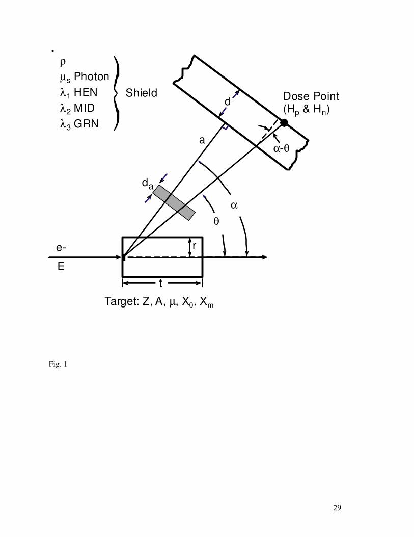
analogous to the Moyer model initially developed for proton machines. As shown in Fig. 1,
SHIELD11 assumes a very simple geometry: a shielding slab of thickness d is located at a
perpendicular distance a and at an angle α with respect to a cylindrical target of radius r and
length t, which is struck by an electron beam with an energy E. The photon and neutron dose
equivalent at the dose point behind the shield at various angle θ relative to beam can be
calculated. Additional “local” shielding of different material, in parallel with slab shield and
situated between the target and the slab shield, can also be taken into account.
Source terms for secondary radiation species generated in the target and their attenuation
in the target itself and the shield are calculated using relatively simple analytical formulas
derived from fits to experimental data and Monte Carlo calculations. Note that the model is
based on a “thick target” assumption, requiring that the EM shower be fully developed in the
target. This implies that the radius should be greater than 1 Moliere unit and the length should be
9
longer than 10 radiation lengths in a given material. Additional consideration for target size is
needed when accounting for neutron attenuation in the target is desired. Further restrictions on
radius and length are imposed in terms of relaxation length for the direct-gamma component
GamD (see below).
The source terms in SHIELD11 are expressed in terms of dose equivalent rate [Sv h-1
] at one
meter from target per kW of beam power. Only production of secondary photons and neutrons is
taken into account, i.e., muons are not considered. The source terms consist of the following five
components:
• GRN (Giant Resonance Neutrons): neutrons generated in the core of the electromagnetic
cascade by means of the giant-resonance production mechanism, with neutron energies
below 20 MeV.
• HEN (High Energy Neutrons): neutrons with energies above 100 MeV, resulting from
hadronic cascade initiated by high-energy photons above the photo-pion production
threshold. This component is the most penetrating and dominates behind very thick
shielding, but it manifests itself mostly by its byproduct, the lower-energy evaporation
neutrons generated in outer layers of the shield.
• MID (Mid Energy Neutrons): neutrons with energies between those for GRN and HEN,
including those generated by means of the pseudo-deuteron production mechanism.
• GamD (Direct Gammas): Photons escaping from the electromagnetic cascade core in a
thick target, with energies in the 0.1 MeV to 20 MeV range. This range corresponds to
the broad minimum in the mass attenuation coefficient for photons, called “Compton
minimum”, of the shielding material. Note the original bremsstrahlung spectrum from
electron interaction with material is a 1/k for thin targets or 1/k2 for thick targets (where k
10
is the photon energy and it can be as high as the electron beam energy). The fact that the
spectrum outside shielding is populated with photons with energies near the “Compton
minimum” region is the result of the spectrum hardening effect in shielding materials.
• GamI (Indirect Gammas): Photons and charged particles resulting from interactions of
HEN and other neutrons in the shield and escaping from the shield material.
Yields and attenuation in the target material are calculated using the following
parameters: atomic number Z and atomic mass A for target, photon mass attenuation factor µ,
radiation length X0 and Molière radius Xm. Parameters used to estimate attenuation in the
shielding material are material density ρ, photon mass attenuation factor µs, and neutron mean-
free-path factors λi, where i = 1, 2, 3 for the three neutron components (in g.cm-2
).
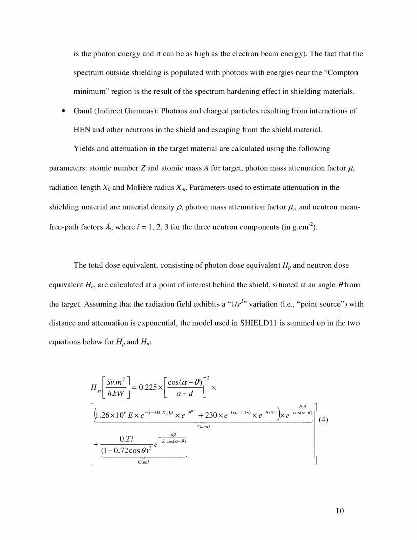
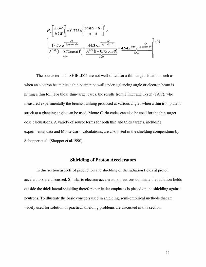
The total dose equivalent, consisting of photon dose equivalent Hp and neutron dose
equivalent Hn, are calculated at a point of interest behind the shield, situated at an angle θ from
the target. Assuming that the radiation field exhibits a “1/r2” variation (i.e., “point source”) with
distance and attenuation is exponential, the model used in SHIELD11 is summed up in the two
equations below for Hp and Hn:
( ) ( )( )
−+
×××+×××
×
+
−×=
−−
−−
−−−−−−
���� ����� ��
������������� �������������� ��
GamI
d
GamD
d
rXt
p
e
eeeeeE
dakWh
mSvH
s
)cos(
2
)cos(72/18.101.06
22
1
6.00
)cos72.01(
27.0
2301026.1
)cos(225.0
.
.
θαλ
ρ
θα
µ
θµθµ
θ
θα
(4)
11
( ) ( )
+−
×+
−
×
×
+
−×=
−−−
−−
−
��� ���� ��
��� ���� ����� ���� ��GRN
d
MID
d
HEN
d
n
eZA
e
A
e
dakWh
mSvH
)cos(66.0
37.0
)cos(
265.0
)cos(
22
3
21
94.4cos75.01
3.44
cos72.01
7.13
)cos(225.0
.
.
θαλ
ρθαλ
ρ
θαλ
ρ
θθ
θα
(5)
The source terms in SHIELD11 are not well suited for a thin target situation, such as
when an electron beam hits a thin beam pipe wall under a glancing angle or electron beam is
hitting a thin foil. For those thin-target cases, the results from Dinter and Tesch (1977), who
measured experimentally the bremsstrahlung produced at various angles when a thin iron plate is
struck at a glancing angle, can be used. Monte Carlo codes can also be used for the thin-target
dose calculations. A variety of source terms for both thin and thick targets, including
experimental data and Monte Carlo calculations, are also listed in the shielding compendium by
Schopper et al. (Shopper et al.1990).
Shielding of Proton Accelerators
In this section aspects of production and shielding of the radiation fields at proton
accelerators are discussed. Similar to electron accelerators, neutrons dominate the radiation fields
outside the thick lateral shielding therefore particular emphasis is placed on the shielding against
neutrons. To illustrate the basic concepts used in shielding, semi-empirical methods that are
widely used for solution of practical shielding problems are discussed in this section.

12
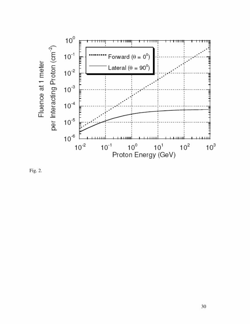
For simple radiation protection calculations, Sullivan (1989) has developed a formula for
the fluence of hadrons with Eo > 40 MeV that will be produced at one meter from a copper target
struck by protons in the energy region 5 < Eo < 500; Eo is in GeV and ( )θΦ is in degree,
( )( )[ ]2
0/352
1
Ε+=Φ
θθ (hadrons cm
-2)(6)
At proton energies between about 0.05 and 5 GeV, this formula also approximately accounts for
the distributions of neutrons per incident proton. This equation is plotted in Fig. 2, for “lateral"
(θ =90o) and "forward" (θ =0
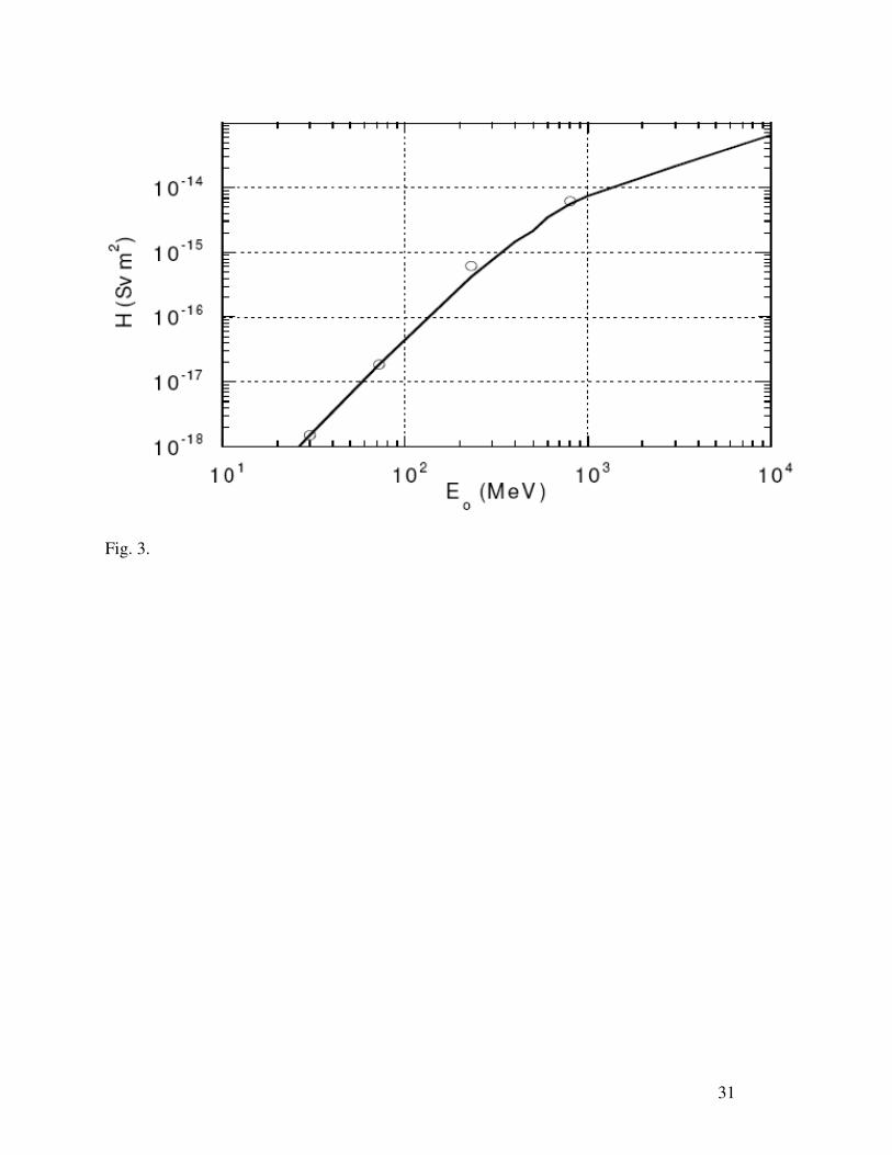
o) directions. The dose equivalent result for θ = 90
o is plotted in
Fig. 3 by Tesch (1985). Above about 1 GeV, the dose equivalent is approximately proportional
to Eo.
Neutron Shielding for Low Energy Incident Protons (Eo < 15 MeV)
Neutron shielding in this region is complex since this is the region of significant nuclear
structure effects. In this energy region, there are many resonances associated with compound
nucleus that can be excited and there are also many nuclear reaction channels leading to a large
number of nuclear excited states up to 20 MeV in excitation energy which have a wide variety of
nuclear structure quantum numbers and very narrow widths in energy. This effect complicates
the shielding of neutrons in this energy range. A method, developed for reactor shielding, that is
applicable to calculate shielding thicknesses in this energy domain is that of removal cross
section theory (Patterson and Thomas 1973). To use the removal cross section method, there
must be sufficient hydrogen in the shield. In this model the dose equivalent, H, as a function of
shield thickness, t, is given by
( ) ( ),exp tPGt r∑−Φ=Η ο (7)
13
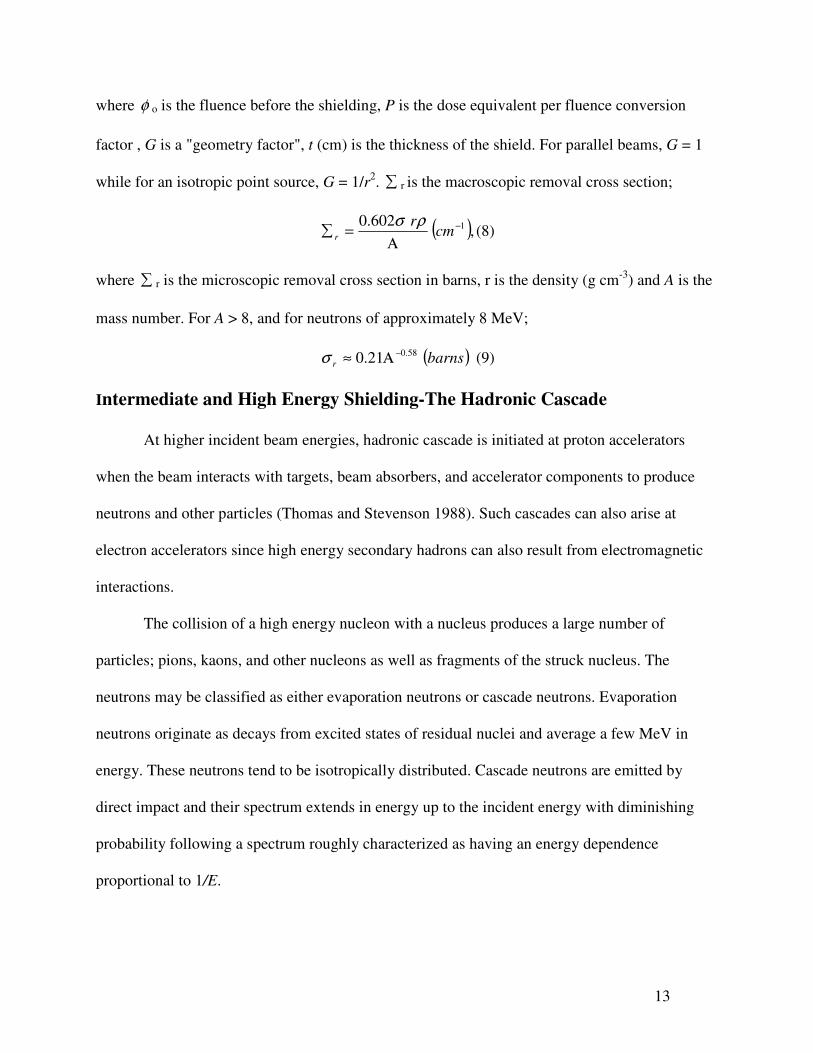
where φ o is the fluence before the shielding, P is the dose equivalent per fluence conversion
factor , G is a "geometry factor", t (cm) is the thickness of the shield. For parallel beams, G = 1
while for an isotropic point source, G = 1/r2. ∑ r is the macroscopic removal cross section;
( ),602.0 1−
Α=∑ cm
rr
ρσ(8)
where ∑ r is the microscopic removal cross section in barns, r is the density (g cm-3
) and A is the
mass number. For A > 8, and for neutrons of approximately 8 MeV;
( )barnsr
58.021.0 −Α≈σ (9)
Intermediate and High Energy Shielding-The Hadronic Cascade
At higher incident beam energies, hadronic cascade is initiated at proton accelerators
when the beam interacts with targets, beam absorbers, and accelerator components to produce
neutrons and other particles (Thomas and Stevenson 1988). Such cascades can also arise at
electron accelerators since high energy secondary hadrons can also result from electromagnetic
interactions.
The collision of a high energy nucleon with a nucleus produces a large number of
particles; pions, kaons, and other nucleons as well as fragments of the struck nucleus. The
neutrons may be classified as either evaporation neutrons or cascade neutrons. Evaporation
neutrons originate as decays from excited states of residual nuclei and average a few MeV in
energy. These neutrons tend to be isotropically distributed. Cascade neutrons are emitted by
direct impact and their spectrum extends in energy up to the incident energy with diminishing
probability following a spectrum roughly characterized as having an energy dependence
proportional to 1/E.
14
As the proton kinetic energy increases, other particles, notably pions and kaons play roles
in the cascade when their production becomes energetically possible. They are absorbed with
absorption lengths comparable in magnitude to those of protons. These particles also decay into
muons. Because of their long ionization ranges and lack of nuclear interactions, muons provide a
pathway for energy to escape the cascade.
In general, the neutrons En > 150 MeV are the principal drivers of the cascade because of
the ionization energy loss for pions and for protons below 450 MeV where the ionization range
becomes roughly equal to the interaction length. Furthermore, neutrons are produced in large
quantities at large values of θ compared with the forward-peaked pions.
Intermediate and High Energy Shielding-Attenuation Length
An important feature of neutron shielding at higher energy (GeV energy region)
accelerators is the fact that the attenuation length becomes an approximate constant at high
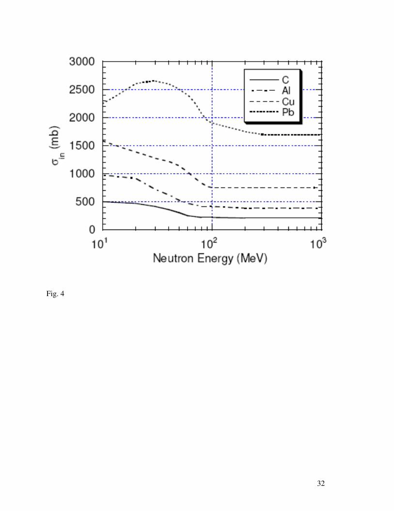
energy. As the energy increases, the neutron inelastic cross sections increase rapidly until about
25 MeV where they generally level off and then fall rapidly with energy in the region
25<En<100 MeV to a value which becomes independent of energy, aside from a slight, gradual
increase at the very highest energies. This fact was discovered early in the history of accelerators
by Lindenbaum (1961). The result is that high energy neutron attenuate approximately
exponentially with an attenuation length, attenλ , that is rather insensitive to energy. Thus, in units
of length,
( )cmN in
attenσ
ρλ1
= (10)
where inσ is the inelastic cross section and N is the number of absorber nuclei per unit volume.
This cross section specifically does not include elastic scattering and so is always smaller than
15
the total cross section. Fig. 4 illustrates the neutron inelastic cross sections for several materials
up to a kinetic energy of 1.4 GeV beyond which it is essentially constant.
Values of the high energy interaction lengths are available for many different materials
and representative examples are provided by Schopper (1990) with extensive tabulations of the
value of inσ (mb) for a variety of particles, energies, and materials in the high energy region as
functions of particle momenta up to 10 TeV/c.
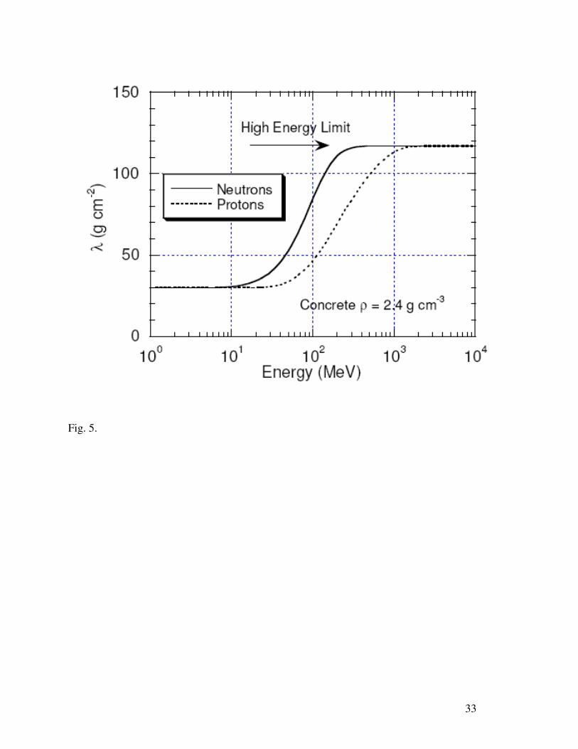
The leveling off of the attenuation length for concrete as a function of particle energy is
of special importance due to the widespread utilization of concrete shielding for hadrons. Fig. 5
gives the results for both neutrons and protons. An important feature of these results is the
equivalence of the attenuation lengths for protons and neutrons at high energies.
Transverse Shielding of High-Energy Proton Accelerators
For both photons and neutrons, transmission through shield can be approximated by
an exponential function. Ideally, the transmission factor, T(z) of a shield of thickness z can be
expressed as
[ ]λ/exp)( zzT −= (11)
where λ is the attenuation length. For a source point, for example neutrons produced in
interaction of a proton beam on a beam intercepting device, the radiation level outside the shield
may be written as
( ) ( )[ ]λθθ θ /exp, 2dHrdH −= − (12)
where r is the distance from the source, d is the shield thickness in the direction θ and λ is the
effective removal mean free path and θH is the source term, that is the radiation level at zero
shield in the direction θH at unit distance from the source.
16
This method, which is a point kernel method, can be used for calculating transverse
shield of high-energy proton accelerators. The Moyer Model that was first developed by B. J.
Moyer to solve particular shielding problems related to the Bevatron at the Lawrence Radiation
Laboratory. The Moyer model is predominantly based on an exponential approximation with
constants fitted to actual data spanning the range of proton beam energies from 7.4 to 800 GeV
(Patterson 1973; Cossairt 2005; NCRP2003; Thomas and Stevenson 1988).
In Moyer model, the dose equivalent outside the shield at an angle of θ from the beam-
target interaction point (see Fig. 6.) is written as
( ) ( )
( )2
( ) exp csc
csc
oH f t
Hr
ρ β ζ θ
θ
Ε − −= (13)
The shield materials are represented by the layers xi and a is the inner radius of the tunnel. The
dose point is at a radial thickness of d and is at a distance rcscθ from the beam-target interaction
point.
i
n
i
xar1=∑+= (14)
The parameter ζ, which replaces the ratio d/λ in the argument of the exponential function, is
introduced to take care of the n shielding components;
i
in
i
x
λς
1=∑= (15)
Moyer model parameters have been determined empirically. (Stevenson et al. 1982; Thomas and
Stevenson1988) from global fits to data over a wide domain of energy that f(θ ) is well described
by
( ) ( )βθθ −= expf (16)
θ is in radians, β is in radians-1
, and, in fact, β ≈ 2.3 rad-1
(for En > 150 MeV) for proton kinetic
energies above a few GeV.
17
The value of Ho(Ep)exp(-βθ) is determined from the yield data and empirical
measurements. Ηο(Εp) is best fit as a power law; Ho(Ep) = kEn. From such results, per incident
proton;
( ) ( ) ( ) ( )
( ) ( )
0.80 0.1013 2
8 2 4 0.8 2
2.84 0.14 10 Sv m
2.84 10 mrem m 2.8 10 mrem cm
H E E
E E
ο ρ ρ
ρ ρ
±−
− −
= ± ×
= × = ×.(17)
These results are derived for relatively "thick" targets (like accelerator magnets) in tunnel
configurations. Schopper et al. (Sc90), based on Monte Carlo results gave values for "thin"
targets of k=2.0 x 10⁻¹⁴
(Sv m2) and n =0.5 recommended values of λ for concrete and other
materials as a function of mass number A are;
Concrete: 22 117201170 −− =± cmgmkg
Others: 23/123/1 8.42428 −− = cmgAmkgA
Since it was first developed in early 1960s Moyer Model has been used in design of shielding
against high energy neutrons in several accelerators. It is a simple and elegant model that can be
readily used for shielding, or a test for results obtained by Monte Carlo methods. However, it is
important to understand the limitation of the model. The source strength parameter was
determined for small target to shield distance and normal to thick targets. Any large deviation of
these conditions may result in wrong shield specifications.(Stevenson 1982)
Shielding Against Muons at Accelerators
Muons at proton accelerators arise from two principal mechanisms from pion and kaon
decay and from direct production. Muons production becomes energetically possible at proton
accelerators of energy above 150 MeV. However, for radiation protection, it will become a
significant issue only when the primary beam energy is above 10-20 GeV for the longitudinal
shield.
18
At electron accelerators, muons are generated by pair-production as well as pion and
kaon decay. However, the fluences produced by direct photo-production is the dominant
mechanism in electron accelerators (Nelson 1968; Nelson et al. 1974a; Nelson et al 1974b).
Muon pair-production becomes possible at photon energies larger than > 211 MeV. Photo-muons
are highly peaked in forward direction (angle < 10 mrad).
Muons are attenuated in the shield through ionization energy loss and multiple scattering.
Radiative losses become important only in the TeV energies. Therefore, the muons are typically
ranged out in the shield. For shielding of very high-energy muons (hundreds of GeV) only the
use of earth as shield is practical. The energy-loss mechanism for muons is dominated by
statistical fluctuations (straggling) at high energies and a significant number of muons have
ranges much larger than the mean range.
Sullivan’s approximation for muons is a method of estimating muon flux densities at
proton accelerators based upon a semi-empirical fit to existing muon production data (Sullivan
1992). Sullivan gives an equation for the flux density of muons per meter of decay path as a
function of shield thickness found along the proton beam axis (that is, on the straight-ahead
maximum of the muons);
Ε−
Ε=Φ
taqexp085.0
2χ(18)
where Φ is the fluence (muons m-2) per interacting proton, E is the proton beam energy (GeV),
χ is the distance of the dose point to the point of production of the pions and kaons (meters), q
is the average path length (i.e., the decay path) of the pions and kaons in air, gases, or vacuum
prior to their absorption by solids or liquids, and α is an effective average energy loss rate (GeV
meter-1) for the muons in a shield of thickness t (meters). For concrete, iron and lead, which
19
comprise the most commonly shield materials for muon shield, α is 9, 23 and 24 GeV m-1
respectively. The full width at half maximum, FWHM, of the muon distribution at the boundary
of such a shield is given by Sullivan;
( )metersat
FWHMΕ
=χ
6.4 (19)
Attenuation by Ducts and Penetrations
All accelerators shields require openings to allow for personnel access, cable ventilations
ducts water pipes, etc. Such penetrations could compromise the integrity of the shield and must
be designed such that they do not undermine the overall efficiency of the shield. Various
methods that are based on experimental data, albedo coefficient, empirical methods and Monte
Carlo simulations exist.
Shield penetrations should not be placed such that there would be a line-of-sight to the
primary beam. Additionally, the sum of shield wall thickness required between the source and
the exit of the penetration should be the same as if the labyrinth were not present.
The existing data shows that incident particle energy or particle type does not affect the
attenuation provided by a labyrinth viewing a source of beam loss other than the fact that the
total yield of "source" neutrons depends on the incident energy and ion type. One can thus
estimate the dose, dose equivalent, or neutron fluence at the exit of a labyrinth by using
attenuation estimates in the legs multiplied by an estimate of the neutron fluence or dose
equivalent found at the entrance, or mouth, of the penetration into the beam enclosure as show in
Fig. 7.
20
For straight penetrations (first leg of a multi-legged access tunnel or shaft), and for the
second, third and all the subsequent legs universal transmission curves are widely used for
different source geometries (Goebel et al. 1972; Cossairt1995). The data are usually presented in
units of d/ A where d is the distance from the source and A is the cross-sectional areas of the
tunnel. The validity of scaling is for a height/width ratio that lies between 0.5 to 2.
Discussion of Shielding Materials
Attenuation of radiation intensities to the design levels can be achieved by a single material,
or a particular combination of materials. Selection of shield materials and configuration could on
factors other than their attenuation properties. To decide upon a final shield design, the following
factors should also be considered (NCRP 2003):
• required thickness and weight of the material
• possibility of use as shielding against photons and neutrons
• uniformity, consistency and homogeneity
• cost, including cost of installation and maintenance
• shield design must be integrated with all other aspects of an accelerator facility
• possibility of induced radioactivity
Experience has shown that three materials concrete-earth and steel are the widely used as
shield materials in high-energy accelerators. Cost considerations at large accelerators direct the
usage of these particular materials. Other materials such as lead, polyethylene are used in special
cases. In low energy electron accelerators, mainly medical and industrial accelerators of less than
10 MeV, lead is the shield of choice.
Earth
The main constituent of dry soil is SiO2 making it an effective shield material for both
21
photons and neutrons. Depending on the soil type, water content and the degree of compaction,
the earth density varies from 1.7 g cm-3
to as high as 2.25 g cm-3
. Earth may be easily put in
place and is usually readily available, especially in large accelerators that are placed
underground.
Concrete
Concrete is the material that is used widely as shielding materials in accelerators, due to
its relative low cost, ease of case to different shapes, good structural properties and use as both
photon and neutron shield. Concrete can be used either in the form of modular and moveable
blocks that can be used as temporary shielding, or as reinforced concrete poured in place as
structure that contains the accelerator. Portland concrete is a relatively standard material with the
density in the range of 2.3-2.4 g cm-3
. Heavy materials can be added in the concrete aggregate,
barites or iron ore, to increase its density and average Z, thus increasing its effective for photon
shielding. The density of heavy concrete can exceed 4.5 g cm-3
, but this will come at a great
increase in cost.
The water content of concrete, which may vary with time, and earth shield is of great
importance in their efficiency for use as shield against neutrons. Residual radiation from 24
Na
produced in concrete can be a major contributor to the ambient radiation levels after accelerator
shut-down. Low-sodium aggregate are used to reduce thermal neutron induced radioactivation of
concrete; alternatively, addition of boron compounds (boron frits) improves the thermal neutron
absorption of concrete shield.
Iron
Iron or steel is widely used for photon shielding due to its relatively high density, low cost and
good structural and thermal properties and ease of fabrication. The density of cast iron can be as
22
low as 7.0 g cm-3
; steel density is typically around 7.9 g cm-3
. Steel, in conjunction with
hydrogenous materials such as concrete, is used for shielding of high-energy neutrons (several
tens of MeV), but is deficiency for shielding low –energy neutrons. Steel contains no hydrogen,
and its lowest inelastic energy level (i.e., in the dominant naturally-occuring iron isotope, 56
Fe) is
847 keV. Additionally, the 27.7 keV resonance and 73.9 keV resonance can result in large fluxes
of soft neutrons outside iron shields. The effective of the relative high energy of the lowest
inelastic energy level in 56
Fe in greatly limiting the effectiveness of iron shielding for low energy
neutrons has been discussed elsewhere (i.e., Elwyn and Cossairt 1986).
Polyethylene
Due to its large hydrogen content (~5% by weight) and its density of 0.92 g cm-3
polyethylene is
used widely in shielding of D-T generators. Thermal neutron capture in polyethylene can lead to
a build up of 2.2 MeV photons which can be mitigated by addition of a boron compound.
ACKNOWLEDGEMENTS
As a review article, this work is essentially a compilation of work done by others listed in
references below, most prominently by Cossairt 2007, , Destabler 1965, Nelson 2005, Thomas
and Stevenson 1988, Shopper et a1 1982, Swanson,1979 and Vyelt and Liu 2001.This work was
supported by Department of Energy Contract DE-AC-03-76SF00515.
23
References
Cossairt JD. Radiation physics for personnel and environmental protection. Rev. 9B. Batavia, IL:
Fermi National Accelerator Laboratory Report TM-1834; 2007. Available at:
http://www-esh.fnal.gov/TM1834_PDF_Files/TM_1834_Revision_9B.pdf. Accessed 22
June 2007.
Cossairt JD. Approximate technique for estimating labyrinth attenuation of accelerator-produced
neutrons. Batavia, IL: Fermi National Accelerator Laboratory Fermilab Radiation Physics
Note No. 118; October 1995.
DeStaebler H. Similarity of shielding problems at electron and proton accelerators, Stanford,
CA: Stanford Linear Accelerator Center Report SLAC Pub. 179; 1965.
Dinter H., Tesch K. Dose and shielding parameters of electron-photon stray radiation from a
high-energy electron beam, Nucl Instr & Meth. 143, 349-355; 1977.
Elwyn AJ, Cossairt JD. A study of neutron leakage through an Fe shield at an accelerator. Health
Phys 51:723-735; 1986.
Fasso A, Ferrari A, Ranft J, Sala PR. FLUKA, a multi-particle transport code.Geneva,
Switzerland: European Center for Nuclear Research Report CERN-2005-10,
INFN/TC_05/11, SLAC-R-773; 2005.
Goebel K, Stevenson GR, Routti RJ, and Vogt HG. Evaluating dose rates due to neutron leakage
through the access tunnels of the SPS. European Center for Nuclear Research Report
CERN LABII-RA/Note/75-10; 1975.
Ipe N, Liu JC. Shielding and radiation protection at the SSRL 3 GeV injector. In: New horizons
in radiation protection and shielding. Proceedings of American Nuclear Society Topical
24
Meeting; Pasco, Washington; 1992.
Iwase H, Niita K, and Nakamura T. Development of general-purpose particle and heavy ion
transport Monte Carlo code. Journal of Nuclear Science and Technology 39: 1142-1151;
2002.
Lindenbaum SJ. Shielding of high energy accelerators. Ann Rev Nucl Sci 11:213-258;1961.
Liu JC, Mao ZS, Nelson WR, Seeman J, Schultz D, Bong P, Gray P, Radiation safety system of
the B factory at the Stanford Linear Accelerator Center. Health Phys.77:588-594,1999.
Liu JC, Bull JS, Drozdoff J, May R, Vylet V. Radiation safety systems for accelerator facilities
Rad Pro.Dos.96:429-440; 2001.
Liu JC, Vylet V, Walker LS. Engineered and Administrative Safety Systems for the Control of
Prompt Radiation Hazards at Accelerator Facilities, this compendium; 2007.
McKinney GW, et al., MCNPX 2.6.X features (2006-2007). Los Alamos National Laboratory
Report LA-UR-07-2053, M&C/SNA 2007.
Mokhov NV.The MARS code system user's guide. Version 13. Batavia IL: Fermi National
Accelerator Laboratory Report FN-628; 1995.
National Council on Radiation Protection and Measurements. Radiation protection for particle
accelerator facilities. Bethesda, MD: NCRP Report No. 144; 2003.
Nelson WR, Jenkins TM. The SHIELD11 computer code. Stanford, CA: Stanford Linear
Accelerator Center Report SLAC-R-737, UC-414; 2005.
Nelson WR, Rokni SH. SHIELD11: A line source application of SHIELD11. Stanford, CA:
Stanford Linear Accelerator Center Report SLAC-TN-06-002; 27 April 2006.
Nelson WR. The shielding of muons around high-energy electron accelerators: Theory and
25
measurement. Nucl Instr & Meth. 66: 293-303; 1968.
Nelson WR, Hirayama H, Rogers DWO. The EGS4 code system. Stanford CA: Stanford Linear
Accelerator Center. SLAC Report No. SLAC 235; 1985.
Nelson WR, Kase KR. Muon shielding around high-energy electron accelerators, part I, theory,
Nucl Instr and Meth 120:401-411; 1974
Nelson WR, Kase KR, Stevenson GR. Muon shielding around high-energy electron accelerators,
Part II, Experimental investigation. Nucl Instr and Meth 120:413-429;1974.
Patterson HW, Thomas R H. Accelerator health physics. New York, NY: Academic Press; 1973.
Rokni SH. et al., Benson EC, Burke DL, Jenkins T, Helson G, Nelson WR, Smith HE,
Tenenbaum, PT, Walz, DR, Vylet, Radiation protection systems for the final focus test
beam at SLAC. Health Phys 71:786-794; 1996.
Schopper H. Fassò A, Goebel K, Höfert M, Ranft J, Stevenson G. Landolt-Börnstein numerical
data and functional relationships in science and technology new series; Group I: nuclear
and particle physics Volume II: Shielding against high energy radiation. O.Madelung, Ed.
Heidelberg and Berlin: Springer-Verlag; 1990.
Stevenson G , Kuei-Lin L, Thomas RH. Determination of transverse shielding for proton
accelerators using the Moyer model. Health Phys 43:13-29; 1982.
Sullivan A H. The intensity distribution of secondary particles produced in high energy proton
interactions. Rad Prot Dos 27:189-192, 1989.
Sullivan A H. A guide to radiation and radioactivity levels near high energy particle accelerators.
Ashford, Kent, United Kingdom: Nuclear Technology Publishing;1992.
Swanson W P. Radiological safety aspects of the operation of electron linear accelerators
26
Vienna, Austria: International Atomic Energy Agency IAEA Technical Report No. 188;
1979.
Tesch K. The attenuation of the neutron dose equivalent in a labyrinth through an accelerator
shield, Part Accel 12:169-175,1982.
Tesch K. A simple estimation of lateral shielding for proton accelerators in the energy range
from 50 to 1000 MeV, Rad Prot Dos 1, 165-172, 1985.
Thomas RH, Thomas SV. Variation and regression analysis of Moyer model parameter data,
Health Phys 46:954-957; 1984.
Thomas RH, Stevenson GR. Radiological safety aspects of the operation of proton accelerators,
Vienna Austria: International Atomic Energy Agency IAEA Technical Report No.
283;1988.
Vylet V. Prompt radiation fields at accelerators; this compendium; 2007.
Vylet V, Liu JC. Radiation protection at high-energy electron accelerators, Rad Prot Dos 96:333-
343; 2001.
27
List of Figure Captions
Fig. 1: Geometry representation used in the SHIELD11 code: Photon and neutron dose
equivalent is calculated at a point behind a primary slab shield. Additional “local”
shielding of different material, situated between the target and the point of interest, can be
taken into account. See text for the meaning parameters describing properties of target
and shielding. HEN refers to neutrons with energies above 100 MeV, MID neutrons have
energies between 100 MeV to 20 MeV, GRN neutrons have energies below 20 MeV.
See text for the meaning parameters describing properties of target and shielding.
Fig. 2. Plot of Eq. for two different values of θ . The proton is interacting in a copper target
[(Sullivan 89).]
Fig. 3. Dose equivalent per proton due to neutrons at θ =90o having energies higher than 8 MeV
at a distance of 1 meter from a copper target. The curve is an interpolation between the
normalized experimental measurements denoted by the open symbols. [Adapted from
Tesch 1985).]
Fig. 4. Inelastic neutron cross sections as a function of energy in the range 1 to 1000 MeV.
[Adapted from (Lindenbaum 1961)].
Fig. 5. The variation of the attenuation length λ for monoenergetic neutrons and protons in
concrete shielding as a function of neutron energy. The high energy limit is 117 g cm-2
.
(Adapted from Stevenson 1982)
Fig. 6. Geometry for the empirical Moyer Model. A beam of protons impinges on the target of
length L. The shield materials are represented by the layers xi; a is the inner radius of the
tunnel. The dose point is at a radial thickness of d and is at a distance rcscθ from the
beam-target interaction point.
28
Fig. 7. Schematic plan view of a typical personnel access labyrinth of three “legs” at a large
accelerator facility that defines the coordinate system and terminology associated with
labyrinth calculations. The (*) denotes the location of a loss of beam at a point adjacent
to the “mouth” of the labyrinth. The lengths of legs after the first are measured between
centers of turns.
Fig. 8. Universal transmission curves for the first leg of a labyrinth as a function of normalized
distance, δ1 from the mouth. The curve for a plane source is also suitable to use with an
off-axis point source. Adapted from (Goebel l975 and Cossairt 1995).
Fig. 9. Universal transmission curve for the second and subsequent legs of labyrinths as a
function of normalized distance from the center of the previous turn, δi.[Adapted from
(Goebel 1975) and (Cossairt 1995).]
29
re-
E
t
Target: Z, A, µ, X0, Xm
θ
α
a
d
α-θ
Dose Point(Hp & Hn)
ρ
µs Photon
λ1 HEN
λ2 MID
λ3 GRN
Shield
da
Fig. 1
30
Fig. 2.
31
Fig. 3.
32
Fig. 4
33
Fig. 5.
34
Fig. 6.
35
Fig. 7.
36
Fig. 8.
37
Fig. 9.