rack & pinion and scotch yoke actuators - flowserve
TRANSCRIPT

Rack & Pinionand Scotch Yoke Actuators

Flowserve is the World’s PremierProvider of flow managementservices. Flowserve manufacturesactuators and accessories to providefull service valve and damperautomation to the worldwide oil andgas, pulp and paper, chemical,processing and energy relatedindustries. We provide maximumvalue to the end user through a broadoffering of products, services,application engineering and oursystematic approach to automation.
Sales and service facilities arestrategically located in industrialcenters throughout the world.
2
Valtek ® Control ProductsSpringville, UtahWeb Site: http://www.flowserve.com
3
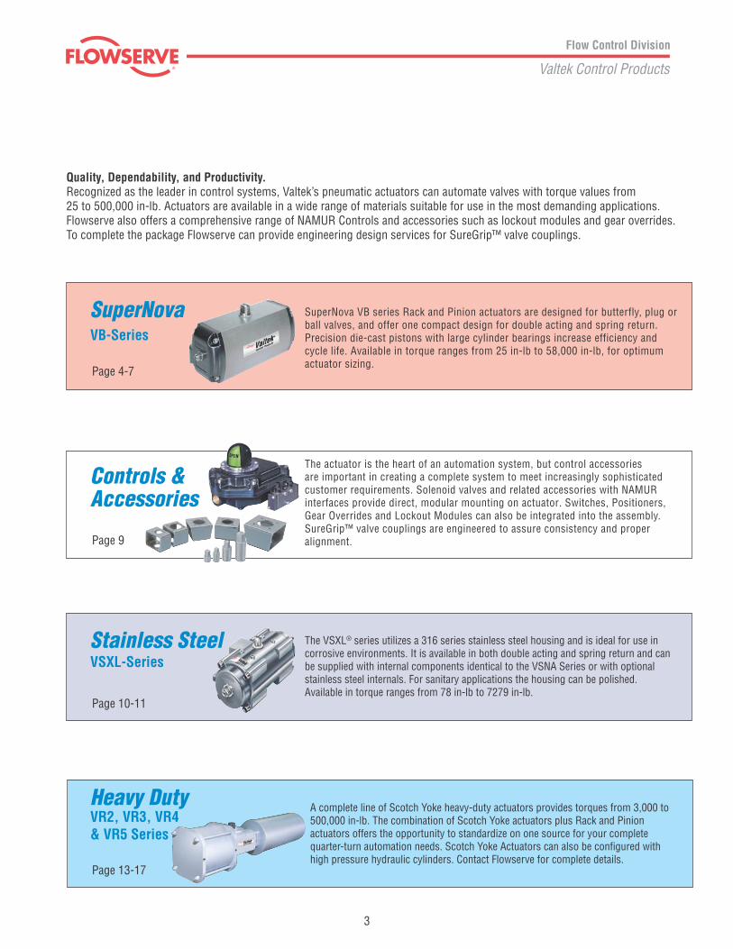
Quality, Dependability, and Productivity.Recognized as the leader in control systems, Valtek’s pneumatic actuators can automate valves with torque values from25 to 500,000 in-lb. Actuators are available in a wide range of materials suitable for use in the most demanding applications.Flowserve also offers a comprehensive range of NAMUR Controls and accessories such as lockout modules and gear overrides.To complete the package Flowserve can provide engineering design services for SureGrip™ valve couplings.
The VSXL® series utilizes a 316 series stainless steel housing and is ideal for use incorrosive environments. It is available in both double acting and spring return and canbe supplied with internal components identical to the VSNA Series or with optionalstainless steel internals. For sanitary applications the housing can be polished.Available in torque ranges from 78 in-lb to 7279 in-lb.
A complete line of Scotch Yoke heavy-duty actuators provides torques from 3,000 to500,000 in-lb. The combination of Scotch Yoke actuators plus Rack and Pinionactuators offers the opportunity to standardize on one source for your completequarter-turn automation needs. Scotch Yoke Actuators can also be configured withhigh pressure hydraulic cylinders. Contact Flowserve for complete details.
Heavy DutyVR2, VR3, VR4& VR5 Series
Page 13-17
Page 10-11
Stainless SteelVSXL-Series
The actuator is the heart of an automation system, but control accessoriesare important in creating a complete system to meet increasingly sophisticatedcustomer requirements. Solenoid valves and related accessories with NAMURinterfaces provide direct, modular mounting on actuator. Switches, Positioners,Gear Overrides and Lockout Modules can also be integrated into the assembly.SureGrip™ valve couplings are engineered to assure consistency and properalignment.
Controls &Accessories
Page 9
SuperNova VB series Rack and Pinion actuators are designed for butterfly, plug orball valves, and offer one compact design for double acting and spring return.Precision die-cast pistons with large cylinder bearings increase efficiency andcycle life. Available in torque ranges from 25 in-lb to 58,000 in-lb, for optimumactuator sizing.
SuperNovaVB-Series
Page 4-7

Rack & Pinion Actuators aredesigned for automating butterfly,eccentric rotary plug or ball valvesand dampers. The actuatorsincorporate a precision-extrudedhard anodized aluminum bodyand a one-piece nitride-coatedpinion gear, factory lubricated fora long trouble-free life. Actuatorsare designed for 100-degree travelwith clockwise and counterclock-wise travel adjustment for openand closed positions. Actuatorsare convertible to a double actingor a spring return simply byremoving or adding springs, whileutilizing the same body and endcaps. Available in torque rangesfrom 25 in-lbs. to 58,000 in-lbs.,for optimum actuator sizing foreach valve requirement.
Field reversible action simply byrotating pistons 180°.
Corrosion resistant hard anodizedaluminum housings with stainlesssteel fasteners.
One compact design for doubleacting and spring return is easilyfield convertible by installing orremoving springs.
Spring ReturnSuperNova VB-Series
4
Broad size range offers optimum actuator
sizing for each valve requirement.

Double Acting (No Spring)
Full length gear engagementbetween piston rack &nitride-coated pinion.
Flats on pinion drive shaftaccommodates wrench overridesand accessories.
Precision die cast pistons withlarge cylinder bearings increaseefficiency and cycle life.
Integral travel stops in both directions with10 degrees of overtravel to assure preciseadjustment of both the openand closed positions.*
*Outward piston adjustment only on models VSNA250 & VSNA300
5
NAMUR mounting dimensions onactuator accessory holesand drive shaft. NAMUR mounting
dimensions on actuatorpneumatic portconnections.
Upper and lower pinionbearings extend life.

Torque OutputsSuperNova VB-Series
Spring Chart VB050 ➁Spring Combination ➀
Spring Group #1 Spring #2 Spring #3 Spring(inner) (low rate outer) (high rate outer)
4 1 ➂ 1 ➂5 26 2 17 1 28 2 29 2 2
Note: ➀ #1 Spring has one color code dot#2 Spring has two color code dots#3 Spring has three color code dots
Spring Chart VB063-VB200Spring Combination ➀
Spring Group #1 Spring #2 Spring #3 Spring(inner) (middle) (outer)
4 25 1 ➂ 1 ➂6 27 1 28 2 29 1➂ 1➂ 210 2 211 1 2 212 2 2 2
6
Spring 60 psi (4.1 bar) 80 psi (5.5 bar) 100 psi (6.9)Air Supply
Air Pressure psi (bar)Actuator 40 (2.8) 60 (4.1) 80 (5.5) 100 (6.9) 150 (10.3)VA32 25 37 50 62 93VB050 78 116 155 194 291VB063 144 216 288 360 539VB085 299 449 598 748 1122VB100 552 828 1104 1380 2071VB115 913 1369 1826 2282 3423VB125 1294 1941 2588 3236 4853VB150 2329 3494 4658 5823 8734VB175 3487 5230 6974 8717 13076VB200 4970 7455 9940 12424 18637VSNA250 10354 15531 20707 25884 38826VSNA300 15529 23293 31057 38822 58232
Model No End Break End Break End Break End Break
VB050 5 36 55 56 766 43 64 46 697 49 73 35 63 74 1028 61 92 15 49 54 88 93 1279 73 110 34 74 73 113
VB063 6 68 102 103 1417 79 119 85 1288 90 136 66 1169 102 153 119 17510 113 170 100 16311 124 186 82 150 153 22212 135 203 135 210
VB085 6 141 211 215 2937 164 246 177 2678 188 282 138 2419 211 317 248 36510 235 352 209 33911 258 387 171 313 320 46312 282 422 281 437
VB100 6 260 390 397 5417 303 455 325 4938 347 520 253 4459 390 585 457 67310 433 651 385 62511 477 716 313 577 589 85312 520 781 518 805
VB115 6 430 645 656 8947 502 753 537 8148 573 860 418 7359 645 968 756 111210 717 1075 637 103311 789 1183 518 954 975 141012 860 1290 856 1331
VB125 6 610 915 930 12677 712 1067 761 11558 813 1220 593 10429 915 1372 1071 157710 1017 1525 903 146411 1118 1677 734 1352 1381 199912 1220 1830 1213 1887
Air Supply Spring 60 psi (4.1 bar) 80 psi (5.5 bar) 100 psi (6.9 bar)
Note: For additional air supply pressures, consult factory or yourAutoSize software program.
DA Torque
VSNA250-VSNA300 Spring CombinationsSpring number is total number of springs in endcaps. There should never be adifference in springs per endcap greater than one. Example: VSNA250S09 wouldhave four springs in one endcap and five in the other.
Model No End Break End Break End Break End Break
VB150 6 1098 1648 1673 22807 1281 1922 1369 20788 1465 2197 1066 18759 1648 2471 1927 283710 1831 2746 1624 263511 2014 3020 1320 2432 2485 359712 2198 3295 2182 3394
VB175 6 1606 2527 2438 34577 1899 2907 2079 31338 2153 3349 1530 28519 2427 3759 2820 429210 2701 4170 2366 398911 2975 4581 1912 3686 3656 543012 3249 4992 3201 5127
VB200 6 2343 3516 3568 48647 2734 4107 2914 44328 3125 4691 2269 40009 3515 5277 4106 605310 3906 5865 3456 562211 4296 6451 2808 5190 5293 767412 4687 7037 4645 7243
VSNA250 6 2854 6591 7421 120257 3393 7690 6448 114418 3945 8788 5428 108579 4519 9887 4373 10273 9780 1545010 5106 10985 3274 9689 8566 1486611 5715 12084 7352 14281 12529 1945812 6343 13182 6138 13697 11314 18874
VSNA300 6 4744 11096 9931 174737 5640 12945 8245 165018 6558 14795 6482 155309 7512 16644 4658 14559 12669 2232610 8487 18493 2762 13588 10625 2135511 9500 20343 8581 20384 16348 2815012 10543 22192 6537 19412 14304 27179
➁ VB050 has maximum of 2 springs per endcap➂ Install springs on opposite sides

Dimensions
7
Note: Double ActingPressure at port “CW” will result in clockwise rotation. Pressure at port “CCW” will result in counter-clockwise rotation.Note: Spring ReturnPressure at port “CCW” will result in counterclockwise rotation. Springs provide clockwise rotation upon loss of pressure.
➀ Actuator shown in the full clockwise (CW)position as viewed from top.
➁ Accessory mounting holes not for gearoverride or stop block.
➂ Cycle times under no load conditions. Air line size, air capacity,and valve torque characteristics affect these cycle times.Faster or slower cycle times can be accomplished using specialcontrol components.
How To Order (Select Bold Type Code from each column that applies)
MODEL
VB050VB063VB085VB100VB115VB125VB150VB175VB200VSNA250VSNA300
Springs (Select One)➀050 Thru 300
040506070809101112
TYPE
D Double ActingS Spring Return (FCW)C Spring Return (FCCW)
SealsBlank - Buna (Std.)
L Low Temp.H Viton (High Temp.)
MaterialsBlank - Std. Hard Anodized
AluminumK K-Mass CoatedW White Epoxy CoatedG Gray Epoxy CoatedX BlackMax Coating
OptionsR Extra Long Travel StopC Stainless Steel Pinion/ Snap Ring
➀Consult torque charts or AutoSize for applicable spring combinations.Example: A model VB100 spring return (FCW) spring set 10, would be coded as VB100S10
B SQ.
C
S RADIOUS
D SQ. x E DP.
L
L/2M
O
R
Q
K/2
K
A/2
A
.157
.16
M6 x 12mm DP.
H J
G NPT SUPPLY (CW)
1.260F
N
P FOR CLEARANCE
.945
M5 x .32 DP.G NPT SUPPLY (CCW)
B1 SQ.
C1

SuperNova Models VSNA250 & VSNA300 90° Units
Dimensions
MODEL A B C D E F G H J K M O P PP Q R S WEIGHTS VOLUME CYCLE TIMEDA&SR 180 NPT DA SR CW CCW CW CCW
VSNA250 27.32 39.14 4.250 5/8-11X.63 2.87 1.850 1.81 11.02 1/2 5.91 11.02 5.118 2.20 1.969 0.98 3.75 1.65 .24 137 172 757 720 5-7 5-7VSNA300 32.60 44.00 5.000 5/8-11X.94 N/A N/A 2.50 13.39 1/2 6.30 13.39 5.118 2.44 1.969 0.98 3.75 1.65 N/A 217 288 1403 1019 6-9 6-9
For “How To Order” see page 7
8
VSNA250
➀ Actuator shown in the full clockwise (CW) position as viewed from top.➁ Accessory mounting holes not for gear override or stop block.➂ Use studs only to mount. Bolts not recommendedP Cycle times under no load conditions. Air line size, air capacity, and valve torque
characteristics affect these cycle times. Faster or slower cycle times can beaccomplished using special control components.

Controls
A25N Directional Valve*The Valtek Directional Valvemounts directly to SuperNovaseries actuators which eliminatesthe cost of tubing and fittings.The valves are available for doubleacting and spring return actuatorswith NEMA 4X, 7 & 9, orintrinsically-safe and low powersolenoid operators. These valveshave been tested and provenreliable for over 1 million cycles.
APS1 Module*The Valtek APS1 module workswith the Valtek A25N solenoidvalve and diverts exhaust air frombetween the pistons into thespring chamber. This preventscorrosive atmospheres from beingpulled into the spring chamber.
APS2 Module*The Valtek APS2 module workswith remote/line mounted solenoidvalves and diverts exhaust air frombetween the pistons into the springchamber. This prevents corrosiveatmospheres from being pulled intothe spring chamber.
LV1 Lockout & Vent Valve*The LV1 Lockout and Vent Valvemodule provides two primaryfunctions. The LV1 may be usedwith a manual override to shut offsupply air and vent actuator ports.The LV1 may also be used as apneumatic lockout valve which,when properly implemented, willsatisfy OSHA Standard 1910.47.The LV1 may be sandwichmounted with other ValtekNAMUR accessories or may beused with the NPT1 adaptor.
FC1, FCDA & FCSR*The ‘FC’ Series Flow Controlmodules provide compact flowcontrols for precise adjustment ofSuperNova actuator speeds. TheFlow Control Modules may besandwich mounted with otherValtek accessories or may beused with the NPT1 adaptor.
Gear Overrides*Declutchable gear overrides are optionswhich allow local manual control ofactuated valves and dampers.The gear overrides are sized for easyoperation and can be combined withother control accessories.
Lockouts*The lockout option permits easy lockout ofautomated valves. Lockouts are designed towithstand the rated output torque of the actuator,with the intent to meet the requirements of OSHAStandard 1910.47 “The Control of HazardousEnergy” (Lockout/Tagout)
UltraSwitch GL/XL/PL Series RotaryPosition Indicators*The UltraSwitch series of positionindicators provides a compact andeconomical package for both visual andremote electrical indication of valveposition. Models are available in both diecast aluminum and non-metallic versions.Suitable for non-hazardous, hazardousand intrinsically-safe applications.
APEX Modular Positioner *Available in both aluminum andnon-metallic versions, the Apex positionercombines precise valve positioning withadvanced features. A modular manifold baseallows 3-15 psi pneumatic control signals, or4-20mA signals with the addition of the I/Pmodule. Models are available for corrosionresistant applications and hazardous locationsas defined by UL, C-UL, CENELEC, and SAA.
Accessories
9
“Pharos” NAMUR Indicator *Provides an economical solution forpositive visual indication of the actuatorposition. Constructed of tough industrialengineered resin, the UltraIndicator canbe used on actuators that utilize aNAMUR mounting interface.
* Consult Individual Catalogs and IOM’s For Additional Information
SureGrip™ Valve CouplingsEliminates deadband between actuators and rotaryvalves to assure optimal performance on critical controlapplications. Especially suggested for use with V-portedplug and ball valves and for packages with Logixand XL90 positioners.
The Aviator rotary position indicatorenclosure with internal pilot solenoid coilprovides a truly integrated package. Itcan easily be converted to a BUSwitch bysimply adding a Fieldbus communicationprinted circuit board.
Aviator and BUSwitch Rotary Position Indicatorwith Internal Pilot Solenoid*

10
Integral Travel Stops in bothdirections with 10 degrees ofovertravel to assure preciseadjustment of both open andclosed positions.
Full Length GearEngagementbetween piston rack& stainless steel pinion.
The VSXL Series utilizes a 316series stainless steel body andis ideal for use in corrosiveenvironments. It is available inboth Double Acting and SpringReturn versions with a maximumdouble acting torque output of7,279 in-lbs. The VSXL Series canbe supplied with stainless steel oraluminum pistons and springs percustomer requirements and is alsoavailable with optional polishedfinishes for sanitary applications.
NAMUR mountingdimensions onactuator pneumaticport connections.
NAMUR mounting dimensions onactuator accessory holesand drive shaft.
Air Purge Modulesare available instainless steel toisolate the internalcomponents ofspring returnactuators from theatmosphere.Stainless steelbreather ventoptional.
Pinion Bearingslocated at the top andbottom of the pinion,eliminate potentialgalling.
Precision Die Cast Pistons with largecylinder bearings increases efficiencyand cycle life. Field reversible actionsimply by rotating pistons 180°.(Optional stainless steel pistonsalso available.)
Flats on Pinion Drive Shaftaccommodates manualoverrides and accessories.
VSXL Series Stainless Steel
Stainless Steel BodyCorrosion resistantStainless Steel bodyand end caps.
11
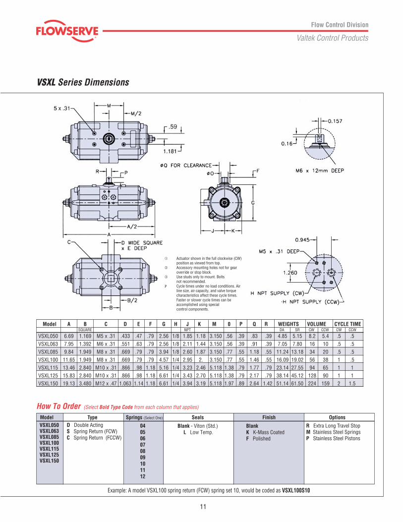
Model Type Springs (Select One) Seals Finish OptionsVSXL050VSXL063VSXL085VSXL100VSXL115VSXL125VSXL150
D Double ActingS Spring Return (FCW)C Spring Return (FCCW)
040506070809101112
Blank - Viton (Std.)L Low Temp.
BlankK K-Mass CoatedF Polished
R Extra Long Travel StopM Stainless Steel SpringsP Stainless Steel Pistons
Model A B C D E F G H J K M 0 P Q R WEIGHTS VOLUME CYCLE TIME
VSXL050 6.69 1.169 M5 x .31 .433 .47 .79 2.56 1/8 1.85 1.18 3.150 .56 .39 .83 .39 4.85 5.15 8.2 5.4 .5 .5VSXL063 7.95 1.392 M6 x .31 .551 .63 .79 2.56 1/8 2.11 1.44 3.150 .56 .39 .91 .39 7.05 7.80 16 10 .5 .5VSXL085 9.84 1.949 M8 x .31 .669 .79 .79 3.94 1/8 2.60 1.87 3.150 .77 .55 1.18 .55 11.24 13.18 34 20 .5 .5VSXL100 11.65 1.949 M8 x .31 .669 .79 .79 4.57 1/4 2.95 2. 3.150 .77 .55 1.46 .55 16.09 19.02 56 38 1 .5VSXL115 13.46 2.840 M10 x .31 .866 .98 1.18 5.16 1/4 3.23 2.46 5.118 1.38 .79 1.77 .79 23.14 27.55 94 65 1 1VSXL125 15.83 2.840 M10 x .31 .866 .98 1.18 6.61 1/4 3.43 2.70 5.118 1.38 .79 2.17 .79 38.14 45.12 128 90 1 1VSXL150 19.13 3.480 M12 x .47 1.063 1.14 1.18 6.61 1/4 3.94 3.19 5.118 1.97 .89 2.64 1.42 51.14 61.50 224 159 2 1.5
SQUARE NPT
VSXL Series Dimensions
How To Order (Select Bold Type Code from each column that applies)
DA SR CW CCW
Example: A model VSXL100 spring return (FCW) spring set 10, would be coded as VSXL100S10
CW CCW
➀ Actuator shown in the full clockwise (CW)position as viewed from top.
➁ Accessory mounting holes not for gearoverride or stop block.
➂ Use studs only to mount. Boltsnot recommended.
P Cycle times under no load conditions. Airline size, air capacity, and valve torquecharacteristics affect these cycle times.Faster or slower cycle times can beaccomplished using specialcontrol components.

Heavy Duty VR-2, VR-3 and VR-4 Series
• Pneumatic, Gas and HydraulicModels
• Double Acting, Spring Return and“Fail-Safe”
• On-Off, Multi-position andThrottling
• Pressure Ranges from 40 psi to150 psi
• Torque Outputs:Standard Design from 1000 to170,000 in-lbs
• Overrides, Special Controls,Line Break Controls, etc.
Piston SealsThe pneumatic series actuatorsutilize a quad seal. This seal hasproven dependable in years oftrouble-free service.
HousingThis unique one-piece housingassures accurate alignment ofboth the torque shaft and thepiston rod.
Spring ModuleThe spring module is aneasily removable,welded cartridge.
Needle Bearings and SealsValtek is the only actuator withprecision drawn cup needlebearings at the torque shaftjournals. The bearings significantlyincrease torque output and cyclelife, while providing near friction-less rotary movement. The sealsprotect the needle bearings fromexternal dirt and corrosion, whilethe bearing’s rigid design prolongsseal life.
Scotch YokeThe slot in the scotch yokemechanism is precision machined.The yoke pin is induction hardenedand chrome plated. The yoke pinrollers are hardened steel.
Piston Rods and Rod BearingsLarge diameter piston rods areguided and supported by extra longbronze bearings. The rods areground, high strength steel with ahard chrome plating polished to amirror finish of 4 to 8 microns.
CylindersThe cylinders are honed to a microfinish with a hard chrome plating.
Valtek has a complete line ofscotch yoke, heavy duty rotaryactuators, which has a uniquebearing design to provide higherefficiencies and longer life.
12

The VRS Series Heavy DutyScotch Yoke Actuator providestorque output as high as500,000 in-lb.• Pneumatic, Gas and Hydraulic
Models• Double Acting, Spring Return
and “Fail-Safe”• On-Off, Multi-position and
Throttling• Pressure Ranges from 40 psi
to 2500 psiThe VR5 series when combinedwith Valtek’s extensive rangeof automation products offers theopportunity to standardize on asingle source for your completequarter-turn automation needs.
Piston Seal and WearbandThe pneumatic series actuatorsutilize a quad seal in conjunctionwith a piston wearband.The quad seal provides a lowfriction, long lasting seal, provendependable for years of troublefree service. The wearbandprovides additional alignment andsupport for the piston seal.
CylinderThe cylinders are honed to amicro finish with a hardchrome plating.
Piston Rods and Rod BearingsPiston rods are guided andsupported by self lubricatingbronze bearings. The rods areground, high strength steel with ahard chrome plating, polished toa mirror finish.
Scotch YokeThe slot in the scotch yokemechanism is precision machined.The yoke pin is induction hardenedand chrome plated. It is supportedat the top and bottom by a guideslot in the housing and the yokepin rollers are hardened steel.
Bearings and SealsLarge diameter bronze/PTFEbearings provide a smooth,low friction surface for the yokejournal. The seals protect thebearings from external dirt andcorrosion, while the bearing’srigid design prolongs seal life.
Identical Mounting PadsValve and accessory mountingpads are located on top andbottom of the body, providingeasy change of fail directionand optional mounting of gearoverride. Two additionalmounting pads are availableon the side of the body formounting accessories.
Indicator/Output shaftTop accessory shaft hasNAMUR slot, and optionalposition indicator.
Spring ModuleThe spring module is an easilyremovable, welded cartridge.
VR5 Dual CylinderSpring Return ActuatorMounted on 36" Metal SeatedHigh-Performance Butterfly Valve.
Heavy Duty VR-5 Series
13
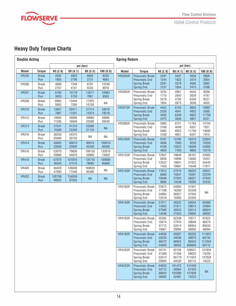
Model Torque 40 (2.8) 60 (4.1) 80 (5.5) 100 (6.9)VR205 Break 3302 4953 6604 8255
Run 1865 2798 3731 4663VR206 Break 4899 7348 9797 12246
Run 2767 4151 5535 6918VR207 Break 6785 10178 13571 16963
Run 3833 5750 7667 9583VR208 Break 8962 13444 17925
Run 5063 7595 10126 NA
VR310 Break 13607 20411 27214 34018Run 7687 11531 15374 19218
VR312 Break 19993 29990 39990 49985Run 11295 16940 22590 28240
VR314 Break 27541 41310 55080Run 15560 23340 31120 NA
VR316 Break 36250 54375Run 20480 30720 NA NA
VR414 Break 40005 60010 80010 100010Run 22600 33900 45200 56500
VR416 Break 53070 79600 106135 132670Run 29980 44970 59960 74950
VR418 Break 67870 101810 135745 169680Run 38343 57515 76685 95860
VR420 Break 84420 126630 168835Run 47690 71540 95380 NA
VR422 Break 102706 154059Run 58022 87033 NA NA
Model Torque 40 (2.8) 60 (4.1) 80 (5.5) 100 (6.9)VR205SR Pneumatic Break 2297 3447 4594 5668
Pneumatic End 1244 1922 2474 2954Spring Break 2291 3379 4595 5882Spring End 1237 1854 2475 3168
VR206SR Pneumatic Break 3235 4961 6543 8268Pneumatic End 1710 2842 3829 4197Spring Break 3379 4793 6349 8527Spring End 1854 2673 3636 4455
VR207SR Pneumatic Break 4452 6755 9003 10987Pneumatic End 2333 4041 4932 5560Spring Break 4595 6349 8923 11759Spring End 2475 3636 4851 6331
VR208SR Pneumatic Break 5880 8721 11764 14704Pneumatic End 3166 4649 6337 7927Spring Break 5882 8923 11759 14692Spring End 3168 4851 6331 7915
VR310SR Pneumatic Break 9187 13785 18379 22824Pneumatic End 4958 7683 9226 10350Spring Break 9189 13522 19049 24993Spring End 4950 7420 9895 12519
VR312SR Pneumatic Break 12937 19849 26167 33083Pneumatic End 6835 10696 13693 16451Spring Break 13522 19841 27022 34443Spring End 7420 10687 14548 17811
VR314SR Pneumatic Break 17813 27015 36023 43937Pneumatic End 8660 14541 19391 22229Spring Break 19049 27022 36027 47043Spring End 9895 14548 19395 25335
VR316SR Pneumatic Break 23672 34892 47047Pneumatic End 11198 18260 25339Spring Break 24993 36027 47043 NA
Spring End 12519 19395 25335VR414SR Pneumatic Break 27017 40522 54034 65906
Pneumatic End 14563 21811 29613 34984Spring Break 27000 40534 53514 68924Spring End 14546 21823 29092 38002
VR416SR Pneumatic Break 35285 52338 70571 87623Pneumatic End 16574 27916 39649 46374Spring Break 37712 53514 68924 89343Spring End 19001 29092 38002 48094
VR418SR Pneumatic Break 44656 65057 89320 111651Pneumatic End 20235 34036 48070 60743Spring Break 48472 68924 89343 111024Spring End 24050 38002 488094 60115
VR420SR Pneumatic Break 55731 82705 109531 137834Pneumatic End 31309 41456 58622 74229Spring Break 53514 85779 111024 137828Spring End 29092 44530 60115 74223
VR422SR Pneumatic Break 64633 101472 131049Pneumatic End 33712 50564 67443Spring Break 68924 103390 137828 NA
Spring End 38002 52481 74223
Spring ReturnDouble Acting
Heavy Duty Torque Charts
14
psi (bar) psi (bar)

Model Torque 40 (2.8) 60 (4.1) 80 (5.5) 100 (6.9)VR514DA Break 73978 110967 147956 184945
Run 44083 66124 88166 110207
VR516DA Break 97370 146056 194741 243426Run 58022 87033 116044 145055
VR518DA Break 123882 185822 247763 309704Run 73820 110730 147640 184550
VR51414DA Break 150393 225589 300786 375982Run 89618 134426 179235 224044
VR520DA Break 153512 230268 307024 383780Run 91476 137214 182952 228691
VR51614DA Break 173785 260678 347570 434463Run 103557 155335 207114 258892
VR522DA Break 186261 279392 372522 465653Run 110991 166487 221982 277478
VR51616DA Break 197177 295766 394355 492944Run 117496 176244 234992 293740
VR524DA Break 222129 333194 444258Run 132365 198547 264729 NA
VR51816DA Break 223689 335533 447377Run 133294 199941 266588 NA
VR51818DA Break 250200 375300 500400Run 149092 223638 298183 NA
VR52020DA Break 309460 464191Run 184404 276607 NA NA
Heavy Duty Torque Charts
Model Torque 40 (2.8) 60 (4.1) 80 (5.5) 100 (6.9)VR516SR Pneumatic Break 156005
Pneumatic End 85871Spring Break NA NA NA 148061Spring End 88837
VR518SR Pneumatic Break 82154 119224 159124 200290Pneumatic End 39519 66535 88990 113660Spring Break 78533 111234 148061 182885Spring End 41956 66740 88837 109731
VR520SR Pneumatic Break 98195 149578 196391 250315Pneumatic End 54881 79902 109761 145647Spring Break 91442 139352 182885 220965Spring End 54865 80127 109731 132579
VR522SR Pneumatic Break 118445 189534 237839 304023Pneumatic End 65755 119400 133171 178232Spring Break 111234 148061 220965 265558Spring End 66740 88837 132579 159335
VR524SR Pneumatic Break 140221 221343 281411 364896Pneumatic End 70545 134713 155620 217507Spring Break 139352 182885 265558 311154Spring End 80127 109731 159335 186693
VR52214SR Pneumatic Break 171600 258112 333706 438098Pneumatic End 101466 153445 186318 269586Spring Break 148061 220965 311154 355748Spring End 88837 132579 186693 213449
VR52416SR Pneumatic Break 208867 318838 424063Pneumatic Break 122237 193047 255551Spring Break 182885 265558 355748 NA
Spring End 109731 159335 213449
VR5 Pneumatic Spring Return Torques
Model Cylinder Size Type Spring Size Override Temperature Material/Coating
Example: A model VR310 spring return (FCW) with 60 psi air supply and viton seals would be: VR310SR60VFor hydraulic or electro-hydraulic actuators, consult factory.Note: In some instances for the VR5 actuator, a second cylinder size is required to complete the model number. Consult torque charts.
VR2
VR3
VR4
VR514-14"dia.16-16"dia.18-18"dia.20-20"dia.22-22"dia.24-24" dia.
.
VR5 Pneumatic Double Acting Torques
05-5" dia.06-6" dia.07-7" dia.08-8" dia.
14-14" dia.16-16" dia.18-18" dia.20-20" dia.22-22" dia.
10-10" dia.12-12" dia.14-14" dia.16-16" dia.
DA-Double Acting Blank- DA Blank-None Blank- Standard 20°-180° F Blank Standard; Epoxy under- (nitrile seals). coat with Polyurethane
SR-Spring Return FCW 40-40 psi air supply G-Declutch Gear V- High Temp. 0° to 300° F top coat (viton seals).
SO-Spring Return FCCW 60-60 psi air supply H- Hydraulic L- Low Temp. -55° to 180°F F-AWWA, specifications intent (nitrile seals, heat treated
80-80 psi air supply J- Jackscrew body) E- Epoxy paint (white)
100-100 psi air supply S- Hydraulic Snubber M- Marine Trim
B- Delutch Gear w/ Hydraulic Snubber
15
How To Order (Select Bold Type Code from each column that applies)
psi (bar) psi (bar)

Model A B C D E F G H J K LDA SR40 SR60 SR80 SR100 DA SR40 SR60 SR80 SR100
VR205 19.82 17.01 29.00 30.00 32.00 33.00 5.75 1.19 1/4 7.19 2.00 9.13 9.13 9.13 9.13 3.00 3.25 2.78 5.75VR206 19.82 17.01 30.00 30.00 32.00 38.00 6.75 1.19 1/4 7.19 2.00 9.13 9.13 9.13 9.13 3.00 3.25 2.78 5.75VR207 19.82 17.01 30.00 32.00 38.00 40.00 7.75 1.19 1/4 7.19 2.00 9.13 9.13 9.13 9.13 3.00 3.25 2.78 5.75VR208 19.82 17.01 33.00 38.00 40.00 41.00 8.75 1.19 1/4 7.19 2.00 9.13 9.13 9.13 9.13 3.00 3.25 2.78 5.75VR310 23.00 18.13 34.00 36.00 39.00 42.00 10.75 0.00 3/8 8.19 3.50 13.25 13.25 13.25 13.25 3.00 4.13 4.44 6.81VR312 23.00 18.13 36.00 38.00 41.00 43.00 12.75 0.00 3/8 8.19 3.50 13.25 13.25 13.25 13.25 3.00 4.13 4.44 6.81VR314 23.50 18.13 39.00 41.00 44.00 45.00 14.75 0.00 1/2 8.19 3.50 13.25 13.25 13.25 14.63 3.00 4.13 4.44 6.81VR316 23.75 18.13 42.00 44.00 45.00 NA 16.88 0.00 1/2 8.19 3.50 13.25 13.25 14.63 NA 3.00 4.13 4.44 6.81VR414 30.87 25.37 50.00 56.00 59.00 55.00 14.75 0.00 1/2 11.56 4.50 14.63 14.63 14.63 16.63 4.50 5.82 6.50 9.75VR416 31.12 25.37 57.00 59.00 55.00 56.00 16.88 0.00 1/2 11.56 4.50 14.63 14.63 16.63 16.63 4.50 5.82 6.50 9.75VR418 31.69 25.37 59.00 56.00 57.00 59.00 20.88 0.00 3/4 11.56 4.50 16.63 16.63 16.63 16.63 4.50 5.82 6.50 9.75VR420 31.94 25.37 59.00 56.00 57.00 59.00 20.88 0.00 3/4 11.56 4.50 16.63 16.63 16.63 16.63 4.50 5.82 6.50 9.75VR422 32.12 25.37 55.00 58.00 59.00 NA 23.75 0.00 3/4 11.56 4.50 16.63 16.63 16.63 NA 4.50 5.82 6.50 9.75
DA SR40 SR60 SR80 SR100
VOLUMES & WEIGHTS Double Acting & Spring Returns
Model M N P R S T U V W X Y AA BB CC DDVR2 5/8-11 1.00 4 5.750 4.25 1.718 .500 1.59 2.000 2.25 .31 1/4-20 .31 4 3.562VR3 5/8-11 1.13 8 7.500 5.00 2.148 .625 3.50 2.500 4.25 .31 1/4-20 .31 4 4.375VR4 7/8-9 1.13 8 11.000 8.00 3.261 .875 4.06 3.750 5.00 .50 3/8-16 ** 8 7.187
ModelNumber
VolumesIn3
Notes:1. All dimensions are in inches.2. Pressure at port side DA1 will result in clockwise rotation, pressure at port DA2 will result in counterclockwise rotation.3. Orientation of accessory output may be indexed 90˚.
16
* VR2 Has only 4 holes at 45°**VR4 8 each 3/8 - 16 x 3/4" deep holes on center line of “DD”
diameter bolt circle are available for accessory mounting.The 3/8-16 x 1" long hex head cap screws must be re-placed by a longer bolt equal to the thickness of themounting bracket. The retainer plate is 1/2" thick.
**VR2-VR3 A clearance hole for a 5/16" hex cap screw and lock-washer may be required to clear the retainer plate boltson the center line of “DD” diameter bolt circle.
Estimated Weights (lbs.)
VR205 137 124 186 189 193 198VR206 198 133 198 202 205 222VR207 269 144 213 218 233 238VR208 352 155 227 244 248 256VR310 550 290 423 435 448 465VR312 792 339 484 496 514 531VR314 1078 401 560 576 593 665VR316 1407 486 661 678 749 NAVR414 1539 665 904 941 968 1127VR416 2010 765 1039 1067 1226 1169VR418 2544 901 1203 1362 1305 1423VR420 3141 1038 1507 1443 1559 1578VR422 3801 1347 1816 1869 1887 NA
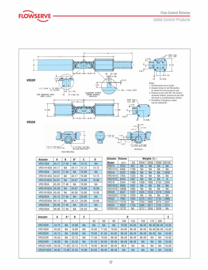
Valve MountingAccessory
Actuator A A* B C D E40 60 80 100 125 150 175 200
VR516SR 44.75 NA 16.88 NA NA NA NA 79.00 84.00 96.49 96.49 96.49 16.00VR518SR 45.00 NA 18.88 NA 76.00 71.50 79.00 84.00 96.49 96.49 96.49 96.49 16.00VR520SR 45.13 NA 20.88 NA 70.00 81.50 84.00 96.49 96.49 96.49 96.49 NA 16.00VR522SR 45.50 NA 23.13 NA 71.50 79.00 96.49 96.49 96.49 96.49 NA NA 16.00VR524SR 46.00 NA 25.50 NA 81.50 84.00 96.49 96.49 96.49 NA NA NA 16.00VR52214SR 45.50 71.88 23.13 14.75 79.00 96.49 96.49 96.9 NA NA NA NA 16.00VR52416SR 46.00 72.88 25.50 16.88 84.00 96.49 96.49 NA NA NA NA NA 16.00
Actuator A B B* C DVR514DA 44.17 17.46 NA 14.75 NAVR51414DA 44.17 NA 44.17 14.75 14.75VR516DA 44.67 17.46 NA 16.88 NAVR51614DA 44.67 NA 44.17 16.88 14.75VR51616DA 44.67 NA 44.67 16.88 16.88VR518DA 45.00 17.46 NA 18.88 NAVR51816DA 45.00 NA 44.67 18.88 16.88VR51818DA 45.00 NA 40.00 18.88 18.88VR520DA 45.13 17.46 NA 20.88 NAVR52020DA 45.13 NA 45.13 20.88 20.88VR522DA 45.50 17.46 NA 23.13 NAVR524DA 46.00 17.46 NA 25.50 NA
VR5DA
VR5SRNotes:1. All dimensions are in Inches.2. Actuator shown in full CW position, as viewed from the accessory side.3. Pressure at port side DA1 will result in clockwise rotation, pressure at port DA2 will result in counteclockwise rotation.4. Orientation of accessory output may be indexed 90˚.
Model (in3) DA SR40 SR60 SR80 SR100 VR514 3233 932 NA NA NA NA VR51414 6466 1199 NA NA NA NA VR516 4222 1066 NA NA NA 2040 VR51614 7455 1333 NA NA NA NA VR51616 8444 1467 NA NA NA /A VR518 5344 1180 1938 1992 2153 2260 VR51816 9566 1581 NA NA NA NA VR51818 10688 1695 NA NA NA NA VR520 6597 1297 2035 2253 2378 2559 VR52020 13194 1929 NA NA NA NA VR522 7983 1463 2276 2437 2725 2888 VR52214 11216 NA 2704 2992 3274 3437 VR524 9500 1730 2686 2811 3155 3274 VR52416 13722 NA 3212 3556 3838 NA
Actuator Volume Weights (lb.)
17

Flowserve Corporation has established industry leadership in the design and manufacture of its products. When properly selected, thisFlowserve product is designed to perform its intended function safely during its useful life. However, the purchaser or user of Flowserveproducts should be aware that Flowserve products might be used in numerous applications under a wide variety of industrial serviceconditions. Although Flowserve can (and often does) provide general guidelines, it cannot provide specific data and warnings for allpossible applications. The purchaser/user must therefore assume the ultimate responsibility for the proper sizing and selection, installation,operation and maintenance of Flowserve products. The purchaser/user should read and understand the Installation Operation Maintenance(IOM) instructions included with the product, and train its employees and contractors in the safe use of Flowserve products in connectionwith the specific application.
While the information and specifications presented in this literature are believed to be accurate, they are supplied for informative purposesonly and should not be considered certified or as a guarantee of satisfactory results by reliance thereon. Nothing contained herein is to beconstrued as a warranty or guarantee, express or implied, regarding any matter with respect to this product. Because Flowserve iscontinually improving and upgrading its product design, the specifications, dimensions and information contained herein are subject tochange without notice. Should any question arise concerning these provisions, the purchaser/user should contact Flowserve Corporationat any of its worldwide operations or offices.
All trademarks and tradenames shown in this literature are property of their respective owners.
For more information, contact:
For more information about Flowserve and its products,contact www.flowserve.com or call USA 972 443 6500
Sales/Manufacturing Facilities1350 N. Mt. Springs Prkwy.Springville, UT 84663 USAPhone 801 489 8611Facsimile 801 489 3719
Manderscheidstr. 1945141 Essen, GermanyTelephone (49) 2 01 89 19 5Facsimile (49) 2 01 891 9600
Alläe du Quartz 1CH-2300 La Chaux-de-FondsSwitzerlandTelephone (41) 32 925 9700Facsimile (41) 32 926 5422
7, Avenue de la Libération, B.P. 6063307 Thiers Cedex, FranceTelephone (33 4) 60 73 80 42 66Facsimile (33 4) 73 80 14 24
FCD VLATB110-00 ©2002 Flowserve Corporation. Flowserve Corporation, Valtek Control Products. Tel. USA 801 489 8611
Quick Response Centers5114 Railroad StreetDeer Park, TX 77536 USATelephone 281 479 9500Facsimile 281 479 8511
104 Chelsea ParkwayBoothwyn, PA 19061 USATelephone 610 497 8600Facsimile 610 497 6680
1300 Parkway View DrivePittsburgh, PA 15205 USATelephone 412 787 8803Facsimile 412 787 1944
12134 Industriplex Blvd.Baton Rouge, LA 70809 USATelephone 225 751 9880Facsimile 225 755 0728
9044 – 18th StreetEdmonton, AlbertaT6P 1K6 CanadaTelephone 780 449 4850Facsimile 780 449 4851
Valtek Rack & Pinionand Scotch Yoke Actuators