raceway design for the innovative blast furnace
TRANSCRIPT

1. Introduction
With the rise of the necessity for the energy saving andfor the measures against environmental problems in recentyears, it is desired to establish the innovative iron-makingtechnology which enables to reduce the amount of energyconsumption and CO2 emissions greatly. In this case, it isnecessary to perform highly efficient operation under lowtemperature circumstances, and reducing gas should besupplied efficiently over the whole region inside the blastfurnace. Therefore, raceway, a part supplying the gas, has tosatisfy the following requirements. 1) Large size 2) Low temperature3) Fast reactionSince raceway is one of the most important parts in blastfurnace, many researchers have studied until now about thegas flow phenomena within raceway and about the combus-tion behaviors of pulverized coal inside raceway.1–4)
Kuwabara et al.1) developed the 1-dimensional racewaymathematical model and made it possible to predict the dis-tributions of gas temperature and compositions inside race-way. In this model, coke particles within raceway weretreated as continuous phase. Additionally the raceway depthand the void fraction inside raceway space were assumed tobe constant. Hatano et al.2) and Nogami et al.3) developed
the 2-dimensional model by use of the similar approach.Their models calculated not only the atmosphere insideraceway but also the shape and size of raceway. However,they neglected the diameter variation of lump coke particlesin gasification. Therefore, their models could not evaluatethe size distributions of coke particles inside and aroundraceway and did not have the ability to express the move-ment of small coke. In addition, it was essentially difficultto represent the discontinuous behaviors of coke particlesas granular materials strictly.
Then, authors have developed the 3-dimensional racewaymathematical model, which used the Discrete ElementMethod (DEM) as analyzing method of coke movement.5,6)
It traces the motion about each lump coke particle existinginside and around raceway. In addition, the heat exchangewith gas and the chemical reactions with gas are consideredin this model. Moreover, the diameters of coke particles arechanged according to gasification. Therefore, the 3-dimen-sional structure of raceway can be predicted strictly togeth-er with the combustion state within raceway.
In this study, first, the outline and verification examplesof the raceway mathematical model are shown. Next, aim-ing at designing the raceway to satisfy the above require-ments, the controllability of raceway by adjusting the blastconditions is investigated. Finally, characteristics of race-way in the top gas recycling process are investigated and
ISIJ International, Vol. 44 (2004), No. 12, pp. 2150–2158
© 2004 ISIJ 2150
Raceway Design for the Innovative Blast Furnace
Hiroshi NOGAMI, Hideyuki YAMAOKA1) and Kouji TAKATANI1)
Corporate Research & Development Laboratories, Sumitomo Metal Industries, Ltd., 1-8 Fuso-cho, Amagasaki, Hyogo660–0891 Japan. 1) Corporate Research & Development Laboratories, Sumitomo Metal Industries, Ltd., 16-1Sunayama, Hasaki-machi, Kashima-gun, Ibaraki 314-0255 Japan.
(Received on June 2, 2004; accepted in final form on July 6, 2004 )
This study tries to design the combustion zone in the highly efficient blast furnace for aiming at great re-duction of energy consumption and environmental loads by use of raceway mathematical model. The modeltreats strictly the discontinuous movement of lump coke particles inside and around raceway, and it consid-ers heat exchange with gas and chemical reactions with gas.
In this study, first, the verification of the model is performed. Next, the controllability of raceway by blastconditions is investigated. Finally, the raceway in the top gas recycling process is evaluated in terms of thesuitability as combustion zone of the novel blast furnace and of the possibility of its realization. The gas re-cycling process has the characteristic of blowing top gas without CO2, pure oxygen and plastics from tuyere.The results obtained in this work are as follows.
1) Raceway mathematical model has the sufficient ability to represent the characteristics of raceway in allcokes operation and PCI operation.
2) The shape and size of raceway and gas temperature in raceway can be controlled by blast temperatureand gas compositions. In addition, nitrogen enrichment in blast is effective to form the uniform and low tem-perature combustion zone.
Raceway in top gas recycling process becomes larger, gas temperature in and around raceway is lowerand volumetric flow rate of bosh gas is less than conventional process. Therefore, raceway conditions in therecycling process enable high productivity and high efficiency.
KEY WORDS: blast furnace; raceway; Discrete Element Method (DEM); mathematical model; nitrogen en-richment; top gas recycling process.

the possibility of its realization in terms of combustionzone appropriate for highly efficient furnace is evaluated.
2. Mathematical Model
2.1. Outline of Mathematical Model
Three dimensional transient analysis model has been de-veloped.5,6) It is a coupling model of Finite DifferencingMethod (FDM) and DEM. In this model, the substanceswithin raceway are assumed to be coke, gas, and pulverizedcoal. On the other hand, since the temperature within race-way is high and the domain can be regarded as dried zone,the existence of liquid is neglected. The treatment of eachphase is shown in the following.
2.1.1. Gas
1) Gas is compressible viscous fluid and obeys the perfectgas law.
2) Effect of turbulent flow is considered by k–e model.7)
3) Combustion rate of gas–gas reactions is calculated byeddy dissipation model.8)
2.1.2. Coke
1) Coke is dispersed particle with sphere shape and themovement is calculated using DEM.
2) Contact force of coke particles is calculated by VoigtKelvin model.9)
3) Gasification rate of coke particles is calculated byshrinking core model,10) in which chemical reaction onthe surface of particle, mass transfer in boundary layer,and gas diffusion inside particle are considered.
4) The diameters of respective coke particles becomesmaller according to the gasification ratio and eachcoke disappears when its diameter becomes less thanone fifth of its initial value.
5) Coke fragments are supposed to exist in packed beds apriori, and the amount of that is determined on thebasis of experimental results.
2.1.3. Pulverized Coal
1) Pulverized coal is dispersed particle consisted of rawcoal, char and ash. Its behavior is described in the fixedcoordinate system.
2) Raw coal can be expressed as CpHqOrNs, and the stoi-chiometric coefficient p, q, r and s are determined byusing proximate analysis value and ultimate analysisvalue.
3) Devolatilization process is described by two competingreactions model.11–13)
4) Combustion rate of volatiles generated at aboveprocess is calculated by eddy dissipation model.8)
5) Char consists of only carbon, and its gasification rate iscalculated by surface reaction model.4)
6) Ash is non-reacting matter and the amount of that in aparticle does not change.
Further, the considered chemical reactions are shown inTable 1.
Under the above assumptions, conservation equations ofmass, momentum and energy are constructed for eachphase. The equations for gas and pulverized coal are de-scribed in Eulerian coordinate system and they are dis-
cretized with the aid of FDM based upon BFC14) (BoundaryFitted Coordinate). Additionally, flow analysis algorithmbased on SOLA method15) is adopted for the purpose of cal-culating the time marching solutions of their equations.With regard to coke phase, the basic equations described inLagrangian coordinate system are constructed for respec-tive coke particles. Their equations expressed in the form ofordinary differential equations are integrated in the time di-rection by use of Runge–Kutta method for mass balanceequation, leap–flog method for momentum balance equa-tion and trapezoid method for energy balance equation.
2.2. Verification of Mathematical Model
In order to verify the mathematical model, the numericalanalysis for hot model test was performed. The schematicfigure of hot model is shown in Fig. 1. The operational con-ditions are as follows; Blast volume is 700 [Nm3/h], Blasttemperature is 800 [°C], and O2 enrichment is equal to10 [Nm3/h]. Further, this analysis was performed for bothall cokes operation and PCI operation. The properties usedin this simulation are shown in Tables 2 and 3.
Figure 2 shows the calculated and measured racewayshapes. Dotted line shows the raceway shapes obtained bythe visual observation using optical fiber in hot model ex-periment. On the shape and size, the calculated raceway al-most accords with the measured value. Raceway shell isshown in Fig. 3. The calculated shell is defined as thecloud, which is constituted of particles with the diameterless than 0.02 [m] and with the local void fraction less than0.4 [�]. Many coke particles contracted by gasificationexist in the calculated shell. On the other hand, the photo-
ISIJ International, Vol. 44 (2004), No. 12
2151 © 2004 ISIJ
Table 1. Chemical reactions (g: gas, s: coke, char).
Fig. 1. Schematic figure of hot model.

graph of the shell was taken after the operation in hotmodel experiment. The calculation neglects the influence ofmelting ash, nevertheless the calculated shell has the struc-ture similar to the shell obtained by experiment. This meansthat the movement of small coke particles contracted bygasification almost determines the formation of racewayshell. Small particles delivered by gas flow to the racewayboundary don’t return inside raceway space and enter intothe packed beds. Then, most of them lose the momentumby collision with coke in packed beds and accumulate onthe surface domain of the packed beds with decreasing theirmass by solution-loss reaction.
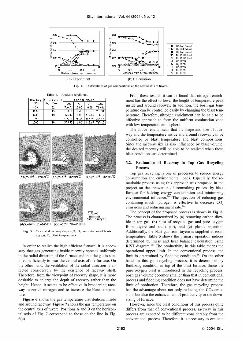
Figure 4 shows the distributions of gas compositions onthe central axis of tuyere in all coke and PCI operations. Inall cokes operation, the calculated results almost agree withthe measured one. On the other hand, in PCI operation, cal-culated results don’t agree with the measured so well, butthere is the contradiction in mass balance of the measuredvalue. Since it is difficult to measure the gas compositionsinside and around raceway in PCI condition, it is consid-
ered that the measured value cannot be so trusted. Thoughthe calculation accuracy is not exact in the current, thismodel has the sufficient accuracy in order to carry out theengineering examination.
3. The Design of Appropriate Raceway for InnovativeBlast Furnace
In the innovative blast furnace to aim at great reductionof energy consumption, low temperature operation has tobe performed. Therefore, the raceway needs to have largesize and high reaction rate. In order to design the racewaysatisfying the above-mentioned requirements, effects oftemperature and composition of the blast gas on the con-trollability of raceway are investigated, and the racewayconditions in top gas recycling process which is one of theprocesses realizing highly efficient furnace are clarified.
3.1. Influence of Blast Temperature and Compositionson Raceway Conditions
The nitrogen enrichment is investigated as the method tochange the compositions of blast gas.
Analysis conditions are shown in Table 4. The blast vol-ume and the amount of nitrogen enrichment were deter-mined under restricting that the bosh gas volume is keptconstant. In this study, bosh gas is defined as the flowingout from the analysis domain.
Figure 5 shows the calculated raceway shapes. As theamount of nitrogen enrichment increases, the height ofraceway tends to become small. It is because the gas tem-perature near the raceway shell becomes low and the gasvolume flowing upward along the shell decreases.Moreover, when the blast temperature rises, the racewaydepth expands slightly. The reason is because it enlarges theimpact energy of the gas flow supplied from the tuyere.
ISIJ International, Vol. 44 (2004), No. 12
© 2004 ISIJ 2152
Table 2. Property of coke. Table 3. Property of pulverized coal.
Fig. 2. Raceway shapes.
Fig. 3. Raceway shell (Bird nests).
In order to realize the high efficient furnace, it is neces-sary that gas generating inside raceway spreads uniformlyin the radial direction of the furnace and that the gas is sup-plied sufficiently to near the central axis of the furnace. Onthe other hand, the ventilation of the radial direction is af-fected considerably by the existence of raceway shell.Therefore, from the viewpoint of raceway shape, it is moredesirable to enlarge the depth of raceway rather than theheight. Hence, it seems to be effective in broadening race-way to enrich nitrogen and to increase the blast tempera-ture.
Figure 6 shows the gas temperature distributions insideand around raceway. Figure 7 shows the gas temperature onthe central axis of tuyere. Positions A and B on the horizon-tal axis of Fig. 7 correspond to those on the line in Fig.6(e).
From these results, it can be found that nitrogen enrich-ment has the effect to lower the height of temperature peakinside and around raceway. In addition, the bosh gas tem-perature can be controlled easily by changing the blast tem-perature. Therefore, nitrogen enrichment can be said to beeffective approach to form the uniform combustion zonewith low temperature atmosphere.
The above results mean that the shape and size of race-way and the temperature inside and around raceway can becontrolled by blast temperature and blast compositions.Since the raceway size is also influenced by blast volume,the desired raceway will be able to be realized when theseblast conditions are determined.
3.2. Evaluation of Raceway in Top Gas RecyclingProcess
Top gas recycling is one of processes to reduce energyconsumption and environmental loads. Especially, the re-markable process using this approach was proposed in theproject on the innovation of ironmaking process by blastfurnace for halving energy consumption and minimizingenvironmental influence.16) The injection of reducing gascontaining much hydrogen is effective to decrease CO2
emissions and reducing agent rate.16)
The concept of the proposed process is shown in Fig. 8.The process is characterized by (a) removing carbon diox-ide in top gas, (b) blast of recycled gas and pure oxygenfrom tuyere and shaft part, and (c) plastic injection.Additionally, the blast gas from tuyere is supplied at roomtemperature. Table 5 shows the primary operation indicesdetermined by mass and heat balance calculation usingRIST diagram.16) The productivity in this table means theoperational upper limit. In the conventional process, thelimit is determined by flooding condition.16) On the otherhand, in this gas recycling process, it is determined by fluidizing condition in top of the blast furnace. Since thepure oxygen blast is introduced in the recycling process,bosh gas volume becomes smaller than that in conventionalprocess and flooding condition does not have determine thelimit of production. Therefore, the gas recycling processhas the advantage about not only reducing the CO2 emis-sions but also the enhancement of productivity or the down-sizing of furnace.
However, since the blast conditions of this process quitediffers from that of conventional process, raceway in thisprocess are expected to be different considerably from theconventional process. Therefore, it is necessary to evaluate
ISIJ International, Vol. 44 (2004), No. 12
2153 © 2004 ISIJ
Fig. 4. Distributions of gas compositions on the central axis of tuyere.
Fig. 5. Calculated raceway shapes (O2: O2 concentration of blast-ing gas, Tb: Blast temperature).
Table 4. Analysis conditions.

not only mass and heat balance in the furnace but also race-way. Then, authors grasped the characteristics of the race-way in this process and evaluated whether it satisfies theraceway requirements for the novel blast furnace or not. Inaddition, the influence of plastic diameter on raceway wasinvestigated.
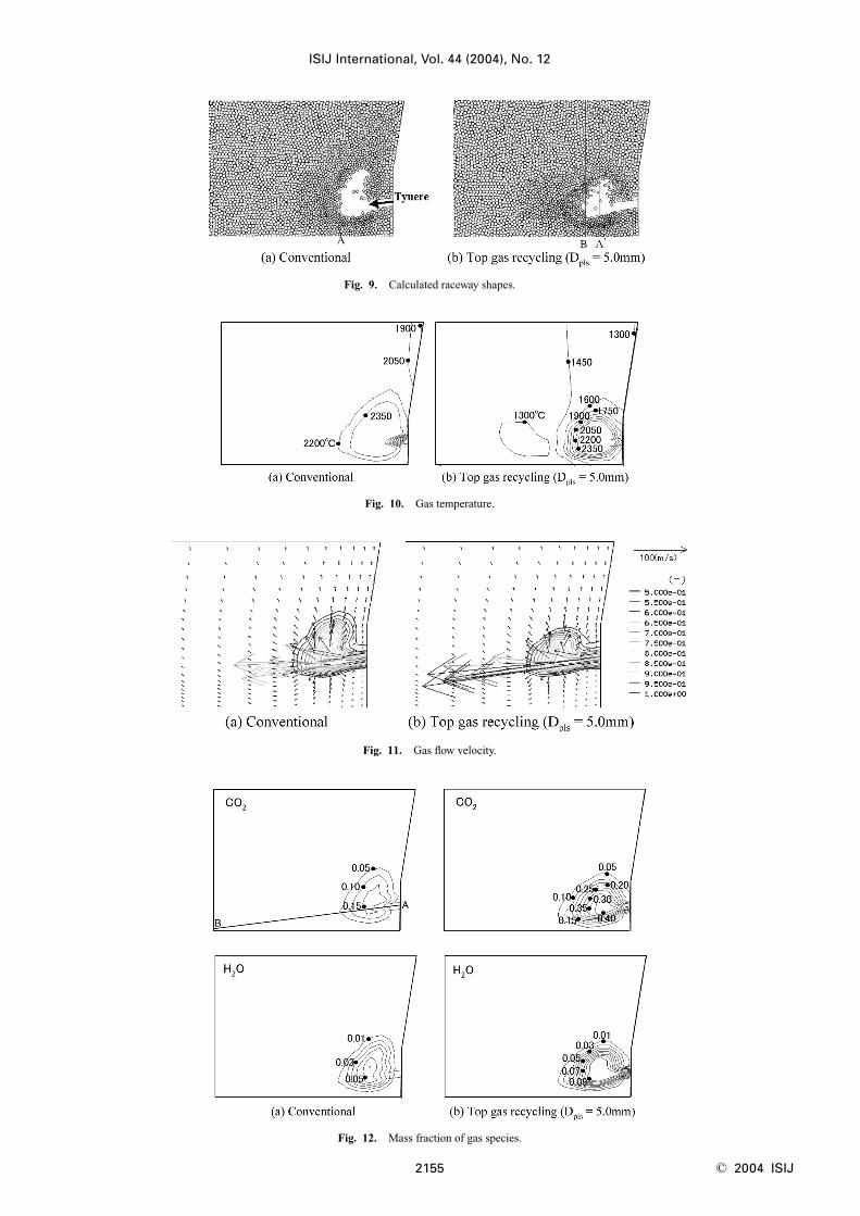
Figures 9–11 show the calculated raceway shapes, gastemperature and gas flow velocity, respectively. Figures 12and 13 show mass fractions of gaseous species (CO2, H2O)and the distributions of gas temperature and components on
the central axis of tuyere.In Fig. 9, line A, A� and B express the raceway depth of
each cases, which were calculated with the aid of the fol-lowing relation formulae between raceway factor Rf andpenetration factor Pf.
17) These formulae were obtained fromthe results of theoretical analysis and cold model experi-ment.
Pf�R f1/3 ....................................(1)
Pf �LR/DT ..................................(2)
Pf �1/2 · rgUg2/(gr cdc) .........................(3)
Here, the depth shown by line A and A� is calculatedunder the assumption that the gas temperature used forevaluating gas density rg is blast temperature. On the otherhand, in case of Line B, it is assumed to be theoreticalframe temperature. The frame temperature should be usedas the gas temperature in this case, since the blast gas burnsin blow pipe.
From Fig. 9, it can be seen that the raceway depth in topgas recycling process is almost equivalent to that in conven-tional process, but the raceway height tends to reduce. Fromthe viewpoint of supplying the gas uniformly inside blast
ISIJ International, Vol. 44 (2004), No. 12
© 2004 ISIJ 2154
Fig. 7. Gas temperature distributions on the central axis oftuyere.
Fig. 8. Top gas recycling process.
Fig. 6. Effect of blast conditions on gas temperature.
Table 5. Primary operation indexes.
ISIJ International, Vol. 44 (2004), No. 12
2155 © 2004 ISIJ
Fig. 9. Calculated raceway shapes.
Fig. 10. Gas temperature.
Fig. 11. Gas flow velocity.
Fig. 12. Mass fraction of gas species.

furnace, the tendency is preferable. In this analysis condi-tions based upon Table 5, the blast temperature of recyclingprocess is much lower than that of the conventional.Therefore, the volumetric flow rate is small and the racewaydepth was expected to become too small as shown in lineA�.
However, as shown in Figs. 12 and 13, gaseous combus-tion of CO and H2 in recycled gas already arises in the blowpipe. Therefore, the gas volume inside raceway increasesconsiderably and the impact energy of gas arriving at theraceway boundaries becomes almost equivalent to that inconventional process. The raceway depth in this recyclingprocess could be kept almost equal to that in the conven-tional and it is remarkable effect in this recycling process.Namely, this blasting method, which blows the com-bustibles in top gas together with pure oxygen into the fur-nace, has the ability to keep the raceway depth even if theblast is injected at room temperature.
By the way, from Figs. 10(b) and 13(b), it can be seenthat there exits local low-temperature domain outside theraceway. Figures 14(a), 15(a) and 16(a) show gas tempera-ture, plastic temperature and volume fraction of plastics, re-spectively, and in Fig. 16(a), the plastic flow vector isshown together. Their displayed domain corresponds to thewhole analysis domain.
These figures show that the rise of plastic temperature isvery slow and that the plastics tend to accumulate on andaround the raceway shell. Since the temperature of accumu-lations is low, gas is cooled down by heat exchange withthem. As a result, the local low-temperature domain shownin Fig. 14(a) is formed. Additionally, in this condition, theplastics were not discharged from the top of the furnace andaccumulated in deadman and on the bottom part, whichcorresponds to the surface part of pig iron.
Next, the improvement of this non-uniform distributionof gas temperature was tried. As mentioned before, the for-mation of local low-temperature domain is caused by accu-mulation of plastic particles with low temperature. Then,their initial diameters were set to one tenth of the base con-dition (�5 [mm]) and the effect of the diameter reductionwas investigated.
The results are shown in Figs. 14(b), 15(b) and 16(b).When the diameter is reduced, the plastic temperature risesfast, and most of plastics are combusted and consumed in-side raceway. Consequently, the accumulation near the shellis avoided, and the non-uniformity of the temperature distri-
bution is improved greatly. Additionally, in base conditions, since the unburned plas-
tic particles got away from the upward gas stream and flowdownwardly, they accumulated in the deadman and on thebottom part considerably. On the other hand, in this case
ISIJ International, Vol. 44 (2004), No. 12
© 2004 ISIJ 2156
Fig. 14. Effect of plastic diameter on gas temperature.
Fig. 15. Effect of plastic diameter on plastic temperature.
Fig. 16. Effect of plastic diameter on volume fraction of plastics.
Fig. 13. Distributions of gas temperature and gas components on the central axis of tuyere.

where the diameters are reduced, the amount of accumula-tions in the domain decreases greatly. It is because the un-burned plastics are entrained by upward gas flow in addi-tion to the improvement of the plastic combustion ratio in-side raceway. The influence of the powder particle diameteron accumulation in the furnace lower part is also examinedin another investigation.18) It was pointed out in the studythat heavy powders like fine coke accumulate in the dead-man and deteriorate the permeability of deadman whentheir diameters are large.18) In this calculation, the densityof plastics is set to 960 [kg/m3], which is almost equal tothat of fine coke. Therefore, the reduction of plastics diam-eters has the effect not only to improve the temperature dis-tribution of combustion field but also to enhance the perme-ability of deadman.
Figure 17 shows calculated raceway shapes. In case thatthe diameter of plastics is made small, the combustion ratioof plastics inside raceway rises and the gas volume insideraceway increases, and the raceway expands slightly.
Macro indices which characterize the raceway of eachprocess are shown in Table 6. Here, the result of top gas re-cycling process corresponds to the case where the plasticsdiameters are reduced. In addition, carbon consumption inthis table means the consumption rate of coke inside andaround raceway, and it was calculated by summing up gasi-fication rate of coke particles existing in the domain.
From theses results, it can be seen that the raceway in topgas recycling process has the following characteristics.1) The raceway depth becomes a little larger. 2) The consumption rate of carbon increases greatly.3) The temperature of bosh gas falls considerably and the
volumetric flow rate becomes small relatively.The increase in consumption rate of carbon is reasonable
result. It is because the concentration of O2 in the blast gasis raised by use of pure oxygen, and because the blast vol-ume is increased in this case for aiming at enhancement ofproduction. Nevertheless, the volumetric flow rate of bosh
gas is smaller than that in the conventional process withless production, and flooding conditions tends to be morerelaxed. Since the blast in this recycling process is per-formed at room temperature, the temperature of bosh gasbecomes low. Therefore, the volume of bosh gas decreases.
In addition, the above characteristics correspond to theraceway requirements already mentioned. Therefore, theraceway in this recycling process is appropriate for the in-novative blast furnace with high efficiency. Additionally,since the raceway does not have disadvantage in compari-son with that of the conventional, it seems that possibilityof its realization is high.
4. Conclusions
For the purpose of reducing energy consumption andCO2 emissions, the design of combustion zone appropriatefor the highly efficient blast furnace was tried with the aidof raceway mathematical model. In this work, the followingresults were obtained.
(1) The verification of the raceway mathematical modelwas performed for the hot model test. As a result, it wasconfirmed that the model could represent sufficiently thecharacteristics of raceway in all coke operation and PCI op-eration. In addition, the verification showed that the modelhas the ability to predict not only the raceway shape and thecombustion state within raceway but also the raceway shell.
(2) The influence of blast temperature and blast compo-sitions on raceway was investigated. Consequently, it wasconfirmed that the shape and size of raceway and its gastemperature could be controlled by these blast conditions.Additionally, it was shown that nitrogen enrichment is ef-fective in forming the uniform combustion zone with lowtemperature atmosphere.
(3) The raceway in top gas recycling process was eval-uated. As a result, it was confirmed that the raceway satis-fied the requirements of combustion zone for the highly ef-ficient blast furnace and that the possibility of the realiza-tion was high. In addition, it was shown that the racewayhas the following characteristics.• The volumetric flow rate of gas inside raceway increases
because of gaseous combustion of top gas in blow pipe.Therefore, raceway size is enlarged even if blast tempera-ture is low.
• With regard to the shape of raceway, the depth is expand-ed and the height is reduced. This tendency is preferablefrom the viewpoint of supplying the gas uniformly overthe whole region of blast furnace.
• The volumetric flow rate of bosh gas decreases becausethe blast is performed at room temperature. Therefore,flooding conditions are relaxed and raceway is stabilized.
Nomenclature
T :Temperature [K]R1,R2 : Particle radius [m]
Sc : Compressive strength [Pa]D : Diameter of lump coke [m]Yi : Proximate analysis [%]
Dpls : Diameter of plastic particles [mm]Pf : Penetration factor [�]Rf : Raceway factor [�]
ISIJ International, Vol. 44 (2004), No. 12
2157 © 2004 ISIJ
Fig. 17. Calculated raceway shapes.
Table 6. Macro indexes to characterize raceway.

LR : Raceway depth [m]DT : Tuyere diameter [m]
g : Gravity acceleration [m/s2]U : Flow velocity [m/s]
Greek symbole : Void ratio [�]r : Density [kg/m3]
Subscriptsg : Gasc : Coke
REFERENCES
1) M. Kuwabara, Y. Hsieh and I. Muchi: Tetsu-to-Hagané, 66 (1980),1918.
2) M. Hatano, K. Kurita and T. Tanaka: 42nd Ironmaking Proc., IronSteel Soc. AIME, Pittsburgh, PA, (1983), 577.
3) H. Nogami, T. Miura and T. Furukawa: Tetsu-to-Hagané, 78 (1992),1222.
4) J. He, M. Kuwabara, and I. Muchi: Tetsu-to-Hagané, 72 (1986),1847.
5) H. Nogami and H. Yamaoka: Proc. of Int. Workshop on Science andTechnology of Innovative Ironmaking for Aiming at Energy HalfConsumption, ISIJ, Tokyo, (2003), 225.
6) H. Nogami, K. Takatani and H. Yamaoka: “Numerical analysis of
blast furnace raceway using coupling model of Discrete ElementMethod and Finite Differencing Method”, CAMP-ISIJ, 18 (2005), inpress.
7) B. E. Launder and D. B. Spalding: Comput. Meth. Appl. Mech. Eng.,3 (1974).
8) B. E. Magnussen and B. H. Hjertager: Proc. 16th Symp. (Int.)Combust., The Combustion Inst., Pittsburgh, PA, (1976), 1657.
9) P. A. Cundall and O. D. L. Strack: Geotechnique, 29 (1979), No. 1,47.
10) K. Hashimoto: Han-nou Kohgaku, Baifukan, Tokyo, (1979), 230.11) H. Kobayashi, J. B. Howard and A. F. Sarofim: Proc. 16th Symp.
(Int.) Combust. The Combustion Inst., Pittsburgh, PA, (1976), 411.12) S. K. Ubhayakar, D. B. Stickler, C. W. von Rosenberg, Jr. and R. E.
Gannon: Proc. 16th Symp. (Int.) Combust., The Combustion Inst.,Pittsburgh, PA, (1976), 427.
13) J. M. Bergess, A. S. Jamaluddin, M. J. McCarthy, J. G. Mathieson, S.Nomura, J. S. Truelove and T. F. Wall: Proc. Joint Symp. of ISIJ andAIMM, ISIJ, Tokyo, (1983), 129.
14) K. Takatani: Tetsu-to-Hagané 74 (1988), 1546.15) C. W. Hirt, B. D. Nichls and N. C. Romero: SOLA-A Numerical
Solution Algorithm for Transient Fluid Flows, Los Alamos Sci. Lab.,Los Alamos, (1975), LA-5852.
16) R. Murai, M. Sato and T. Ariyama: Proc. of Int. Workshop onScience and Technology of Innovative Ironmaking for Aiming atEnergy Half Consumption, ISIJ, Tokyo, (2003), 205.
17) H. Yamaoka and K. Nakano: Tetsu-to-Hagané, 86 (2000), 733.18) H. Nogami, P. R. Austin, J. Yagi and K. Yamaguchi: ISIJ Int., 44
(2004), 500.
ISIJ International, Vol. 44 (2004), No. 12
© 2004 ISIJ 2158