raaf williams (point cook) redevelopment electrical …
TRANSCRIPT

PREPARED BY: WEBB AUSTRALIA GROUP (VIC) PTY LTD ABN 61 073 585 305 [email protected] www.webbaustralia.com.au
LEVEL 9 128 EXHIBITION STREET VIC 3000 AUSTRALIA T +61 3 9652 0333
CONSULTING ENGINEERS ELECTRICAL LIGHTING MECHANICAL SECURITY COMMUNICATIONS AUDIO VISUAL
BRISBANE CANBERRA GOLD COAST MELBOURNE SUNSHINE COAST SYDNEY
EST02008-01-0932-AZ000-RPT-EL-0001 REV D.DOCX
RAAF WILLIAMS (POINT COOK)
REDEVELOPMENT
ELECTRICAL MASTER PLAN
& DEVELOPMENT PLAN

RAAF WILLIAMS (POINT COOK) REDEVELOPMENT ELECTRICAL MASTER PLAN AND DEVELOPMENT PLAN
EST02008-01-0932-AZ000-RPT-EL-0001 REV D.DOCX 2 OF 38 WEBB AUSTRALIA GROUP (VIC) PTY LTD ISSUE D SDR ABN 61 073 585 305
RAAF WILLIAMS (POINT COOK)
REDEVELOPMENT ELECTRICAL MASTER PLAN
& DEVELOPMENT PLAN
Copyright © 2021 Webb Australia Group (VIC) Pty Ltd. All rights reserved. This specification may not be reproduced or transmitted in any
form or by any means in part or in whole without written permission of Webb Australia Group (VIC) Pty Ltd ABN 61 073 585 305
Document Status
Rev No.
Date Amendment Author Reviewer Approved By
Name Name Signature Name Signature
A 03.03.2021 CDR (Draft) B Harding G Lowe
B 25.08.2021 SDR B Harding G Lowe
C 06.09.2021 SDR B Harding G Lowe
D 13.10.2021 SDR (Final) B Harding G Lowe
TABLE OF CONTENTS
1. BACKGROUND ....................................................................................................................... 4
2. EXISTING INSTALLATION ........................................................................................................ 5
2.1 INCOMING SUPPLY ................................................................................................................... 5
2.1.1 Supply Configuration............................................................................................................... 5
2.1.2 HV Intake and Primary Switching Station .................................................................................. 5
2.1.3 HV Rings and Interconnector Cables ........................................................................................ 5
2.1.4 Capacity ................................................................................................................................ 5
2.1.5 Condition ............................................................................................................................... 6
2.1.6 Reliability ............................................................................................................................... 6
2.1.7 Redundancy........................................................................................................................... 6
2.2 EXISTING LOADS ....................................................................................................................... 6
2.2.1 Magnitude .............................................................................................................................. 6
2.3 LOAD DISTRIBUTION ................................................................................................................. 6
2.3.1 Load Profile ........................................................................................................................... 6
2.3.2 Power Factor ......................................................................................................................... 7
2.4 PRIMARY DISTRIBUTION ........................................................................................................... 7
2.4.1 Configuration ......................................................................................................................... 7
2.4.2 Condition ............................................................................................................................... 7
2.4.3 Reliability and Redundancy ..................................................................................................... 7
2.5 SECONDARY DISTRIBUTION ..................................................................................................... 7
2.5.1 Configuration ......................................................................................................................... 7
2.5.2 Capacity ................................................................................................................................ 7
2.5.3 Reliability and Redundancy ..................................................................................................... 8
2.6 POWER CONTROL AND MONITORING SYSTEM (PCMS) ............................................................ 8
2.7 DEFICIENCIES ........................................................................................................................... 8
2.7.1 Incoming Supply (Primary Distribution) Capacity ....................................................................... 8

RAAF WILLIAMS (POINT COOK) REDEVELOPMENT ELECTRICAL MASTER PLAN AND DEVELOPMENT PLAN
EST02008-01-0932-AZ000-RPT-EL-0001 REV D.DOCX 3 OF 38 WEBB AUSTRALIA GROUP (VIC) PTY LTD ISSUE D SDR ABN 61 073 585 305
2.7.2 Incoming Supply Reliability and Redundancy ........................................................................... 8
2.7.3 Capacity ............................................................................................................................... 8
2.7.4 Secondary Distribution Capacity .............................................................................................. 8
2.7.5 Secondary Distribution Reliability ............................................................................................ 8
2.7.6 Distribution Substations .......................................................................................................... 8
3. PROPOSED BASE LOADS ........................................................................................................ 9
3.1 FACILITIES TO BE ADDED TO THE RAAF WILLIAMS (POINT COOK) .......................................... 9
3.2 FACILITIES TO BE DEMOLISHED ............................................................................................... 9
3.3 FACILITIES TO BE REFURBISHED/ADAPTIVE REUSE ................................................................ 9
3.4 ULTIMATE BASE LOAD .............................................................................................................. 9
4. ELECTRICAL MASTER PLAN .................................................................................................. 10
4.1 INCOMING SUPPLY ................................................................................................................. 10
4.2 HV DISTRIBUTION ................................................................................................................... 10
4.2.1 General Arrangement ........................................................................................................... 10
4.2.2 Primary Distribution .............................................................................................................. 10
4.2.3 Secondary Distribution ......................................................................................................... 11
4.3 EMERGENCY POWER GENERATION ...................................................................................... 11
4.3.1 Generation .......................................................................................................................... 11
4.4 POWER MONITORING SYSTEM .............................................................................................. 11
4.4.1 System Requirement ............................................................................................................ 11
4.4.2 Recommendation ................................................................................................................. 11
5. DEVELOPMENT PLAN ............................................................................................................ 12
5.1 INCOMING SUPPLY ................................................................................................................. 12
5.1.1 Powercor works ................................................................................................................... 12
5.2 SECONDARY DISTRIBUTION ................................................................................................... 12
5.2.1 Substation Replacements ..................................................................................................... 12
5.3 STAGING OF THE WORK ......................................................................................................... 12
5.4 EMERGENCY POWER GENERATION ...................................................................................... 12
5.4.1 CEPS ................................................................................................................................. 12
5.5 POWER CONTROL & MONITORING SYSTEM (CPMS) ............................................................... 12
5.5.1 Implementation..................................................................................................................... 12
6. REFERENCES ....................................................................................................................... 14
6.1 REFERENCED DOCUMENTS.................................................................................................... 14
6.2 ABBREVIATIONS ...................................................................................................................... 14
APPENDIX A DRAWINGS .......................................................................................................... 15
APPENDIX B COST ESTIMATE ................................................................................................... 16
APPENDIX C LOADS TBA ......................................................................................................... 17
APPENDIX D POWER FACTOR CORRECTION CALCULATION ....................................................... 18

RAAF WILLIAMS (POINT COOK) REDEVELOPMENT ELECTRICAL MASTER PLAN AND DEVELOPMENT PLAN
EST02008-01-0932-AZ000-RPT-EL-0001 REV D.DOCX 4 OF 38 WEBB AUSTRALIA GROUP (VIC) PTY LTD ISSUE D SDR ABN 61 073 585 305
1. BACKGROUND
RAAF Williams (Point Cook) is the home of Defence aviation in Australia dating back to 1911
RAAF Williams (Point Cook) has had limited investment in infrastructure and facilities and is consequently in need of a major upgrade.
This master plan has been prepared using the guidelines of the MIEE and electrical principles developed by Webb in consultation with Defence in a number of similar master plans for Defence establishments.
RAAF Williams (Point Cook) is the oldest continuously operating military airfield in Australia and is listed on both the National
Heritage List, and Commonwealth Heritage List. The Base provides a secure military airhead for the greater Melbourne area and
aerodrome operations for Defence and authorised civilian aircraft. The Base’s historical legacy and heritage values, coastline
location and airfield capability make it a unique Defence asset.
RAAF Williams (Point Cook) currently supports limited functions following the cessation of flying training activities in the early 1990s.
Consequently, there has been limited infrastructure investment, resulting in degradation of infrastructure and assets.
The Base requires a significant redevelopment of its existing assets and infrastructure in order to sustain the existing capability and
realise its 2040 Future Plan.
The layout of the Base and a large majority of the buildings have significant heritage values. ‘Point Cook Air Base’ is entered on both
the National Heritage List, and Commonwealth Heritage List for its historic, rare, representativeness, social and associational values.
The Base is also recognised on the Victorian Heritage Register, the Victorian War Heritage Inventory, and the National Trust of
Australia (Victoria). Development will consider the maintenance, preservations and adaptive reuse of significant heritage assets in
line with the EPBC.

RAAF WILLIAMS (POINT COOK) REDEVELOPMENT ELECTRICAL MASTER PLAN AND DEVELOPMENT PLAN
EST02008-01-0932-AZ000-RPT-EL-0001 REV D.DOCX 5 OF 38 WEBB AUSTRALIA GROUP (VIC) PTY LTD ISSUE D SDR ABN 61 073 585 305
2. EXISTING INSTALLATION
2.1 INCOMING SUPPLY
2.1.1 Supply Configuration Incoming supply The electricity supply to RAAF Williams (Point Cook) is received and metered at High Voltage (HV) from the DNSP
(Powercor) incomer. LV 4 The HV Incoming Supply is at 22kV.
The electricity supply from Powercor’s 22kV distribution network is via a short radial overhead spur,taken from their overhead
network which runs along Aviation Road, north of the Base. The conductor immediately outside the Base is a ‘Neptune’ (19/3.25
AAC), which has a current carrying capacity of 243A or 9.3MVA.
The Powercor network upstream of this point comprises sections of both underground and overhead conductors, details and capacity
of which could not be confirmed with the DNSP.
There is no overhead lightning shielding conductor on the overhead line sections in the network just outside of the Base. The 2013
Strategic Analysis and Zone Options report stated that the Base and surrounding areas experience a high electricity failure rate and
there is uncertainty about the electricity supply network to meet the needs of future development at the Base.
At the time of the 2008 GHD HV System report, the HV Incoming supply from Powercor originated from the Laverton Zone
Substation (ZSS), via Feeder LV005 which supplies a total of 4500 other customers in the area, in addition to Defence. The Base is
at the extremity of that feeder. There is a Powercor circuit breaker upstream of the site at the Zone substation.
The ZSS feeder LV4 has a capacity is 380A and is currently utilised to 327A at 22kV.
The 22kV feeder to the Base is not dedicated to Defence, and there is no redundancy of supply as the final section of the HV
incoming supply to the Base, being a short radial overhead line spur to the entrance to the Base, presents a single and common
point of failure.
In the 2014 BEAP report, Powercor advised that the feeder to the Base can be interconnected at several points, to allow supply to
the Base to be restored in the event of an upstream fault on Powercor’s network. The switching can be done using remote controlled
network switches by Powercor, with the first opportunity of interconnection to an alternate feeder being approximately 310m from the
Base.
At the Base entrance, the overhead supply terminates to a pole mounted switch (SW 21908, on Pole 91) owned and operated by
Powercor and transitions to an underground cable via a cable termination, which is fitted with lightning surge arresters. The
underground cable connects to the Powercor ground-mounted 22kV metering cubicle, just outside of the 22/11kV transformer
outdoor fenced-compound. The assets downstream of the 22kV metering cubicle are owned and operated by Defence.
Further liaison with Powercor will be required to receive up to date information on the load status of the feeder in Point Cook Road,
as the area is developing rapidly with more housing coming on line.
2.1.2 HV Intake and Primary Switching Station
There is one HV Intake Substation (ISS) at RAAF Williams (Point Cook) located at the entrance to the Base. The ISS is a brick/masonry building (Building S81). Electricity is received from Powercor at 22kV and stepped down to 11kV using a single 22/11kV Dyn11 oil-filled transformer, rated for 2.5MVA with +/- 5% off-load tap changer.
The transformer is manufactured by ASET and was built in 1989 (i.e.greater than 25 years old). The transformer is housed outside the ISS in a fenced compound. The transformer 11kV star point is directly and solidly connected to earth, and does not restrict the earth fault currents. The 22kV cable from the Powercor metering cubicle enters the 22kV section of the Defence-owned ISS and supplies a small two-panel, one-bus 22kV switchboard. A Yorkshire (YSF6 22kV 1250A) 16kA removable circuit breaker supplies the 22/11kV step down transformer. The protection for the transformer circuit includes:
• Overcurrent / Earth Fault protection using GEC MCGG relays
• Transformer differential protection using GEC MBCH relays
• Transformer auxiliaries protection using Buchholz gas and pressure relay.
The ISS also houses a three-panel, one-bus 11kV switchboard, which is supplied from the 11kV side of the step down transformer. The three switchgear are Yorkshire (YSF6 11kV) removable circuit breakers. The three 11kV circuits are:
• 11kV Main Isolator
• Substation No.1 Ring Main Unit (RMU)
• CEPS Ring Main Unit (RMU).
2.1.3 HV Rings and Interconnector Cables
Defence owns, maintains and operates a small 11kV HV network at RAAF Williams ( Point Cook) which comprises the following:
• An 11kV HV ‘Ring Feeder’ between the ISS and the ‘CEPS’ RMU, which supplies HV Substations 1, 3 and 2 (towards the northern are of the base). The open point is at HV Substation 3.
• An 11kV ‘Interconnector’ (which does not supply any HV Substations) links the ISS and the ‘CEPS’ RMU. The interconnector feeder travels south from the ISS to the ‘CEPS’ RMU
• An 11kV ‘Radial Feeder’ from the ‘CEPS’ RMU which supplies HV Substations 4 and 5 (towards the Southern side of the Base). It travels south along Williams Road. The label ‘CEPS’ is a misnomer, as there is no CEPS at RAAF Williams (Point Cook). The ‘CEPS’ RMU is a Kiosk RMU unit with 3 x circuit breakers and no generating units. A CEPS connection was planned as a future addition but never materialised. The 2008 GHD HV System report stated that the HV Interconnector cable is a 95mm² XLPE/HDPE cable, rated for 230A (or 4.4MVA). The report stated that the HV Ring feeder and the Radial Feeder are 70mm² XLPE cables, rated for 195A (or 3.7MVA). The details (size and rating) of all HV Ring and Radial feeders are unknown and not shown on the HV SLD. The CMS was unable to provide confirmation of the ring size and rating. The ring cable conductors (Al or Cu) could not all be confirmed due to lack of labelling.
2.1.4 Capacity
The Distribution Network Service Provider, Powercor, have not provided up to date information on the status incoming supply feeder. HV Feeder.

RAAF WILLIAMS (POINT COOK) REDEVELOPMENT ELECTRICAL MASTER PLAN AND DEVELOPMENT PLAN
EST02008-01-0932-AZ000-RPT-EL-0001 REV D.DOCX 6 OF 38 WEBB AUSTRALIA GROUP (VIC) PTY LTD ISSUE D SDR ABN 61 073 585 305
2.1.5 Condition
The condition of the overhead incoming feeders is generally satisfactory although there have been several reported faults. Powercor have advised that this section of their reticulation is very vulnerable to faults due to the overhead installations transiting large areas of vegetation.
2.1.6 Reliability
We have no information at this time regarding the reliability of the Powercor feeder in Point Cook Road. Further liaison with Powercor will provide the information for the next iteration of this report.
2.1.7 Redundancy
We have no information at this time regarding the redundancy of the Powercor feeder in Point Cook Road. Further liaison with Powercor will provide the information for the next iteration of this report.
2.2 EXISTING LOADS
2.2.1 Magnitude
After inquiries to the Supply Authority Powercor, consumption information was gathered for the 12-month period starting September 2019 and ending October 2021. The peak demand of the RAAF Williams (Point Cook) was recorded at 434 kVA.(approximately 11 A at 22 kV) during November 2019 as obtained from the Powercor data.
The data reveals the impact of Covid 19 pandemic upon the reduced load throughout most of 2020 due to the population reduction at the Base.
There is no Base wide generating capability at RAAF Williams (Point Cook) other than two local emergency generators (LEG) that provide emergency power for the Communications Centre Building (Comcen) P145 and the Building P9.
A generator located in building P25 as part of substation No 2 is not utilised, and as part of the Redevelopment project will be removed from site
2.3 LOAD DISTRIBUTION
Load Types
In general terms, the Base may be divided into two general load-type groups, offices and air side flight control and offices
• Offices loads typically comprise fluorescent lighting, air conditioning and appliance loads whose magnitude corresponds to the general level of human activity during the day and some night activity.
• Air side accommodation consists of flight control buildings, aircraft hangers for the museum displays, the main museum buildings and aircraft parks.
• Load Estimates
Of the 5 distribution substations, some have Maximum Demand Indicators from which metered demands can be obtained, however a portion of those are faulty and not reliable. At this time actual load determination for each substation could not be accurately determined. When the buildings occupancy returns to normal pre Covid 19 levels a more accurate determination of load will be carried out.
Substations for the Base are connected in single ring main configuration. i.e. two radial feeds are connected with two parallel interconnection points each with a normally open point.
Each limb of the ring main is identified by the first substation it connects to outside the intake substation and the HV switches are labelled accordingly The limbs of the ring main have had their open points arranged so that each limb shares approximately half the load.
The maximum demands for the incoming feeder (i.e. for each limb of the ring main) have been obtained from the DNSP over the year of September 2019 to October 2020:
The Laverton zone substation feeder is not dedicated to the Base as it transits several civilian areas of Point Cook and environs before it arrives at RAAF Williams (Point Cook) .
The load on the feeder as communicated by UE is 327Amps (12.5 MVA) of which RAAF Williams (Point Cook) uses 11 Amps (413 kVA).
The above load information has been supplemented with conductor and cable capacities from section 2.5, to calculate utilisation, shown below in Table 2. These are current-carrying capacities, and do not account for limitations related to voltage drops.
2.3.1 Load Profile
Utilising information from Powercor (the current energy retailer) obtained in October 2020, annual and daily load profiles have been produced. These can be found in Figure 1 below.
The sample period for this data is the 12 month period from the 1st of September 2019 to the October 2020.
Figure 1 Monthly Maximum Demand (Sept 19 to Oct 20)
As can be seen from the annual load profile, greater demand has occurred in the time frame previous to the Covid 19 pandemic and a general reduction in load has emerged from the first lock down period of March 2020 until October 2020.
The significant data for typical analysis can therefore only be determined from the period before Covid 19 which as shown is the period September 2019 to February 2020.
Examining the daily load profiles for typical summer day (in Figure 2 below), demand rises quickly in the early morning until 06:30 AM and then rising steadily until 02:30, PM then declines until 07:00 PM, then steadily declining to a minimum at 11:00 PM. This dip in demand signifies that there is little night activity at the Base. The total variance in demand over a day is approximately 300 kVA. The outstanding peak demand for the 31 January is repeated over several weeks during January and February only, and only on

RAAF WILLIAMS (POINT COOK) REDEVELOPMENT ELECTRICAL MASTER PLAN AND DEVELOPMENT PLAN
EST02008-01-0932-AZ000-RPT-EL-0001 REV D.DOCX 7 OF 38 WEBB AUSTRALIA GROUP (VIC) PTY LTD ISSUE D SDR ABN 61 073 585 305
individual days. Generally, the peak demand for all other periods is below 400 kVA. The winter profile shown in Figure 3 indicates a similar characteristic to the summer profile but at a lower average..
Figure 2 Summer Daily Load Profile
Figure 3 Winter Daily Load Profile
2.3.2 Power Factor
Information provided by Powercor indicates that the average power factor at the Base is 0.87. The data provided spanned from September 2019 to October 2020. Over those 12 months, the power factor ranged from 0.711 to 0.93. This shows that the Base is not in compliance with the National Electricity Rules (AEMC) minimum power factor requirement of 0.90.
2.4 PRIMARY DISTRIBUTION
2.4.1 Configuration
Under normal operation, electrical supply is taken from the LV 4 feeder to the Intake Switching Station The incoming feeder is terminated directly onto the HV 22 kV switchboard in the ISS
2.4.2 Condition
The condition of the incoming network equipment is unknown, with no known shortcomings. The ABS had no visually detectable faults.
2.4.3 Reliability and Redundancy
RAAF Williams (Point Cook) is afforded no redundancy, as the LV4 feeder is the only connection to the Base
2.5 SECONDARY DISTRIBUTION
2.5.1 Configuration
The HV network consists underground distribution throughout all areas.
The existing configuration is best described as a single ring, consisting of two limbs interconnected at two points and a number of radial feeds off the main ring. Open points are maintained in the two interconnectors.
Distribution substations are connected to each system via spurs or ring main units (RMU).
2.5.2 Capacity
Not all of the cable and conductor capacities that make up the various reticulation could be ascertained.
All underground HV cables are labelled at the respective ring main unit where they are terminated and all cables are 95 mm sq. Cu XLPE
Voltage Drop Consideration
The RAAF Williams (Point Cook) is not a large Base and HV circuits are of the order of 5 kilometres in length. At the supply voltage of 11 kV it is not anticipated that voltage drop will be an issue for the Redevelopment Project forward for the next 20-25 years.
Overhead Reticulation
There is no HV overhead reticulation at RAAF Point Cook.
Distribution Substations
Some substations installed do not have LV service protective device. A fault on the LV board would rely on the MV fuses to blow, which may have such a delay that no practical protection is provided at all. This arrangement does not comply with mandatory statutory requirements and is a safety hazard.

RAAF WILLIAMS (POINT COOK) REDEVELOPMENT ELECTRICAL MASTER PLAN AND DEVELOPMENT PLAN
EST02008-01-0932-AZ000-RPT-EL-0001 REV D.DOCX 8 OF 38 WEBB AUSTRALIA GROUP (VIC) PTY LTD ISSUE D SDR ABN 61 073 585 305
The status of the existing substations presented in the BEAP report for compliance condition and capacity are tabulated below. These have also been validated as part of the Redevelopment Project.
Table No 1 Substations Status
Substation Compliance Date of original Installation Condition Capacity
HV Sub/RMU 1 Non-compliant 1988 Poor Within limits
HV Sub/RMU 2 Non-compliant 1971 Poor Within limits
HV Sub/RMU 3 Non-compliant 1996 Fair Within limits
HV Sub/RMU 4 Non-compliant 1971 Poor Within limits
HV Sub 5 Compliant 2016 Good Within limits
“CEPS” RMU Compliant 2016 Good Within limits
Overall service status Non-compliant Poor Within limits
Overall precinct status Non-compliant Within limits
2.5.3 Reliability and Redundancy
Reliability
At this time there is no anecdotal evidence of reliability issues at RAAF Williams (Point Cook)
Redundancy
There is no redundancy available for the incoming power supply HV network.
2.6 POWER CONTROL AND MONITORING SYSTEM (PCMS)
There is no PCMS at RAAF Williams (Point Cook). Only some of the distribution substations are equipped with Maximum Demand Indicators (MDIs), however some of these are not functional.
Some substations are fitted with smart meters the readings from which have been used to measure peak load demand.
Also most buildings at RAAF Williams (Point Cook) are fitted with smart meters from which the load estimations for this report have been determined.
2.7 DEFICIENCIES
2.7.1 Incoming Supply (Primary Distribution) Capacity
The supply authority Powercor have not advised to date the status of the power supply capacity, ongoing liaison with Powercor will address these issues.
2.7.2 Incoming Supply Reliability and Redundancy
As the supply from the Laverton Zone Substation is susceptible to lightning strikes, wind-blown debris, fauna and other external factors. These impacts negatively on both the reliability on the supply feeder LV4
2.7.3 Capacity
TBA
2.7.4 Secondary Distribution Capacity
The existing secondary capacity is sufficient, and the use of 95 mm sq underground cables is now allowable under the latest version of Section 26 of the MIEE. However taking into account the potential estimated maximum demand of the ring main circuits and the requirement to maintain a 50 % reserve capacity it has been decided to install 120 mm sq cables.
2.7.5 Secondary Distribution Reliability
As the secondary distribution is all underground cable construction it is considered as reliable.
2.7.6 Distribution Substations
Some of the newer distribution substations have LV boards that lack a main circuit breaker. This is a non-conformance with AS/NZS 3000, as the transformer, LV and HV cabling have no overload protection. The reliance on MV fuses provides little protection under overload as it will only operate for a fault. These arrangements are unsafe, as an earth fault in the board would appear as a low-level phase-to-phase fault on the MV side. The MV fuses may take minutes to operate (if they operate at all).
Six of the distribution substations are equipped with Schneider RMUs. These are well known in the industry for being reliable. These are protected with fuses in the RMU.
The distribution substations are adequately labelled.

RAAF WILLIAMS (POINT COOK) REDEVELOPMENT ELECTRICAL MASTER PLAN AND DEVELOPMENT PLAN
EST02008-01-0932-AZ000-RPT-EL-0001 REV D.DOCX 9 OF 38 WEBB AUSTRALIA GROUP (VIC) PTY LTD ISSUE D SDR ABN 61 073 585 305
3. PROPOSED BASE LOADS
3.1 FACILITIES TO BE ADDED TO THE RAAF WILLIAMS (POINT COOK)
The Redevelopment Project has no new buildings.
3.2 FACILITIES TO BE DEMOLISHED
At this time no buildings are intended to be demolished as part of the redevelopment.
3.3 FACILITIES TO BE REFURBISHED/ADAPTIVE REUSE
The Redevelopment Project anticipates approximately three existing buildings to be refurbished to various levels either minor refurbish or full adaptive reuse as tabled below
Table 2 Buildings refurbished and adaptive reuse
Precinct Additional Load (kVA)
Comments
Building 33 Kitchen Mess and LIA
365
New fully equipped kitchen added to refurbished LIA wing
Removed from scope however may re emerge in DDR.
Load considered for SDR
Building 87 50 Removed from scope
Museum Alternations 20 Removed from scope
Total 365
The resultant effect of the Redevelopment Project works loads diversified minus the facilities to be demolished and adding in the buildings for adaptive reuse is 415 + 365= 780 kVA site total load.
The analysis of load growth across the RAAF Williams (Point Cook) HV network for the next several years considers two elements:
The addition of new (or expansion of existing) facilities.
A load growth factor of 3% per annum has been allowed for future load growth, for the years 2022 through to 2042.
3.4 ULTIMATE BASE LOAD
Considering the Redevelopment Project scope, the electrical demand of the Base is given in Table 4. The additional load has been added February 2023 until completion in June 2025.
Beyond the completed construction program, a 3 % load growth factor has been applied for the remainder of the 20 year period up to the year 2042.
The Total projected Base load after all planned expansion and disposal works are completed – is 1.34 MVA in 2042.
Figure 4 shows this data graphically, including the total capacity of the existing incoming supply arrangement as advised by Powercor.
Figure 4 Projected Base Load to 2042
The total capacity of the incoming LV4 is 9.8 MVA and the expected total load growth for the next 20 years is expected to reach 1.45 MVA this does not allow for other customers on this feeder.

RAAF WILLIAMS (POINT COOK) REDEVELOPMENT ELECTRICAL MASTER PLAN AND DEVELOPMENT PLAN
EST02008-01-0932-AZ000-RPT-EL-0001 REV D.DOCX 10 OF 38 WEBB AUSTRALIA GROUP (VIC) PTY LTD ISSUE D SDR ABN 61 073 585 305
4. ELECTRICAL MASTER PLAN
4.1 INCOMING SUPPLY
The RAAF Williams (Point Cook) Redevelopment Project Brief requires the following;
“a. Investigate, assess and provide recommendation for redundancy in the existing feeder, including by duplicating the feeder between the Powercor meter and intake switching station;
b. Investigate, assess and provide recommendation for the need to renew, replace or provide new signage and fire safety equipment in accordance with Statutory Regulations, Australian Standards, BCA-NCC and Defence requirements at the HV intake switching station;
c. Investigate, assess and provide recommendation for renewal or replacement of earthing to the HV intake switching station in accordance with Statutory Regulations, Australian Standards, BCA-NCC and Defence requirements;”
Duplication of the existing feeders has been assessed and, it is recommended that provision for two (2) off 22 kV supplies be connected to a new Intake Switching Station (ISS), consisting of a second circuit breaker metering assembly for termination of a second future supply.
Both supplies would be connected from the existing 22 kV overhead lines that presently enter the Base from the Powercor.
At this time a second feed to the Base is not possible.
New signage and fire safety equipment will be provided in all substations that are to be retained and new kiosk substations as required.
Earthing testing will be performed at several areas across the Base before SDR stage to determine the earthing requirements and ensure compliance with codes.
It is intended to relocate the incoming power supply to a new ISS and decommission the existing ISS. A new Intake Switching Station will be built to house the 22 kV switchgear and the relevant accessories for operation.
The projected load growth is shown against the proposed upgrade in supply in Figure 4, and Table 6
4.2 HV DISTRIBUTION
4.2.1 General Arrangement
The general arrangement adopted for HV networks at Defence establishments is for distribution substations to be connected as a ring main. These ring mains are connected between major switching nodes, called Primary Switching Stations (PSS) so that the ring mains is connected to a different PSS at each end. At RAAF Williams (Point Cook) there is no PSS (s) the incoming supply is routed directly via the ISS. It is proposed to have one ring main circuit on the Base.
There is a moveable open point on the ring mains that can be used to change how much of the ring main is fed from one circuit breaker at the ISS and how much is fed from the other in order to facilitate power transfer in the event of an outage.
This arrangement allows a high degree of flexibility as it allows any failures in the HV network to be quickly bypassed using switching operations and power restored until equipment or cables are repaired.
The existing ISS does not have sufficient space to accommodate the required numbers of 22 kV circuit breakers to connect the circuits proposed in the Master Plan. For this reason it is recommended to install a new ISS as detailed below.
4.2.2 Primary Distribution
Existing ISS Location Building P81
The existing ISS is located in Building P81 and consists of 2 No 22 kV “Yorkshire” SF6 circuit breakers. One circuit breaker controls the single incoming supply from Powercor. The other breaker controls the 22/11 kV transformer.
The room in which the existing circuit breakers are installed is considered unsatisfactory as reported in the BEAP Report as follows
• Poor earthing at this location.
• Emergency and exit lighting and signage not installed.
• No protection grading, fault level, arc flash studies or earthing reports have been provided.
Although these issues can easily be remedied, the following more serious issues were discovered during recent investigations.
• The space restraints for accommodating further circuit breakers is a limiting issue, there is provision for an additional circuit breaker to be installed at either end of the existing switchboard, for a total complement of 5 No circuit breakers. This would not be adequate for the ultimate design for the site which would require at least ten circuit breakers to be installed.
• There would be considerable down time in inserting a second Powercor feed. This would require a complete shutdown of the site service for several days.
• There is no room to accommodate the Power Control and Monitoring System (PMCS) as required by the MIEE.
• Vintage of the existing superseded Yorkshire switchgear. This would require new switchgear and protection devices.
• Conversion of the site to 22 kV by removal of the isolation transformer and the existing 22 kV and 11 kV switchboard and replace with a single 22 kV switchboard.
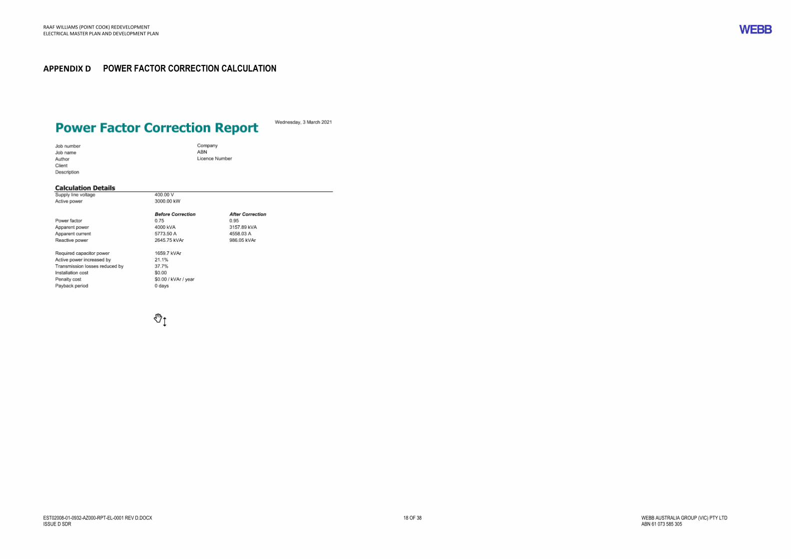
• The power factor for the Base is outside the limits required by the MIEE (0.9 or above) and power factor correction will have to be employed There is insufficient space to locate an external Power Factor Correction (pfc) module local to the ISS. This unit would also require a further 22 kV circuit breaker.
Proposed ISS Location
Under the proposed supply option a new Intake Switching Station would be constructed.
There are four principal considerations in locating the new ISS:
• Easy access for the incoming overhead feeders from Powercor and allowing adequate free space for construction,
• There are no heritage issues with this location.
• Cable routing for the ring main will be more efficient using this site.
• Ease of installing the new cabling for the ringmains whilst the existing ISS is still in service, and then cutting over to the new ISS when all substations are complete.
The auxiliary systems and the 22 kV switchboard would be located in the ISS building. Adequate space would be allowed within the switchroom buildings to accommodate the PCMS equipment, and UPS and other auxiliaries as required by the MIEE.
It is recommended that a new ISS on a new site be provided as part of the Redevelopment Project to offer flexibility in the future for connection of a ring main circuit.

RAAF WILLIAMS (POINT COOK) REDEVELOPMENT ELECTRICAL MASTER PLAN AND DEVELOPMENT PLAN
EST02008-01-0932-AZ000-RPT-EL-0001 REV D.DOCX 11 OF 38 WEBB AUSTRALIA GROUP (VIC) PTY LTD ISSUE D SDR ABN 61 073 585 305
Power Factor Correction (PFC)
Bulk power factor correction consisting of IP66 enclosures would be installed external to the ISS on a concrete slab.
Refer to Appendix D for calculation details.
4.2.3 Secondary Distribution
The existing secondary reticulation is required to be reviewed as described in the Redevelopment project Brief as follows
The new ring mains cabling will be designed for a system fault level of 250 MVA for one second. For this reason a minimum cable size of at least 185 mm2 Al/XLPE will be provided. This cable has a capacity of 275A (10.5 MVA) when installed in conduit, will be employed, as a construction expedient, to enable trenches to be backfilled once conduits are installed. The cable is also used by supply authorities is in most cases widely available and cost effective compared to the equivalent copper cable.
• The present substations loads have been summated;
• Known planned loads have been added to certain rings;
• 3% annual growth has been added to each ring, in proportion to each ring’s current load.
The ring is shown on drawings in Appendix A.
Table 7 Master Planned Load (refer to tables 3,4 and 5 for details of loads)
Ring / Radial Diversity Diversified
Planned Load (MVA)
Ring Load (including 3% load growth)
(MVA)
Ring Capacity (MVA)
Loaded Capacity
Ring main 0.8 415 kVA x .8 =0.332
1.35 10.8 12.5%
The above ring capacities are based on 185 mm sq Al cables in order to meet the requirement that any one cable shall be able to support the entire base load (should the neighbouring feeder be out of commission) and maintain a 50 % reserve capacity.
Operations During Equipment or Cable Failure
Following the failure of HV equipment or cables on the ringmains, the fault is quickly isolated using switching operations so that power can be restored. This involves moving the ring open point.
The proposed new arrangement allows for the ring feeders to be fed from either end, to effectively isolate and bypass any faults that occur on the network. The new network configuration will effectively eliminate the existing spur connected transformers and provide alternate supply routes for these substations.
4.3 EMERGENCY POWER GENERATION
4.3.1 Generation
There is no centralised emergency power generation at RAAF Williams (Point Cook) however, there are two local emergency generators at Sub station 1 Pillar No1 that supports Building P9 and building P 145 Comcen.
Defence have advised that a CEPS is not required for this Base however it is intended to fit out one of the substations No 2 as a future CEPS that will be fitted with the necessary switchgear and interconnector cable for future generator insertion at substation 2 when required.
4.4 POWER MONITORING SYSTEM
4.4.1 System Requirement
The existing control and monitoring infrastructure is limited to stand-alone MDI meters installed at a selection of substations, smart meters in most buildings and these is manifestly inadequate.
4.4.2 Recommendation
A comprehensive PCMS is required to monitor substation and supply loading. This system would be extended to all of the substations within RAAF Williams (Point Cook) area of the Base.
The PCMS system will consist of a PLC network run over a dedicated fibre-optic communications backbone designated the Defence Engineering Services Network (DESN). A new DESN will be utilised.
The user interface will consist of a commercially available SCADA package such as CITECT running on a PC. Such a system will allow remote monitoring of electrical engineering services from a central location, such as the ISS.
Monitoring Functions
The PCMS would have the following monitoring functions:
ISS switchboard
• Remote control of ISS 22 kV switchgear from within a dedicated control room within the ISS.
• Power flows on each incoming and outgoing circuit
• Open/closed/tripped status of each circuit
• Switchboard fault indications, e.g. trip circuit supervision
• DC system parameters and status
• RMU and communications faults
Distribution Substations
• Remote control at each substation location via a free standing physically isolated remote control panel.
• Open/closed/tripped status of RMU
• Power flows at substation LV switchboard, both incoming and outgoing
• RMU and communications faults
Process Alarms
Various alarms and status, including sewerage pumping stations, and local emergency generators.
The PCMS would be utilised as a monitoring system only and would not be used for control.
The RMUs and the low voltage outgoing switches will be fitted with auxiliary contacts which are used to indicate trip and open positions. Such information can also be collected by the PCMS, and indicated on the PCMS computer.

RAAF WILLIAMS (POINT COOK) REDEVELOPMENT ELECTRICAL MASTER PLAN AND DEVELOPMENT PLAN
EST02008-01-0932-AZ000-RPT-EL-0001 REV D.DOCX 12 OF 38 WEBB AUSTRALIA GROUP (VIC) PTY LTD ISSUE D SDR ABN 61 073 585 305
5. DEVELOPMENT PLAN
This section details the works that will be undertaken as part of the RAAF Williams (Point Cook) Redevelopment Project
5.1 INCOMING SUPPLY
5.1.1 Powercor works
The following works will be negotiated with Powercor:
• Upon construction and fit out of a new ISS a new feed will be connected to the circuit breaker in the new ISS. This will involve removal of the existing metering enclosure and the 22/11 kV transformer
• Disconnection of the existing ISS, removal of the overhead “tee off” feeding the existing ISS. This work to proceed once the new ring mains secondary distribution for the Base is ready to be cut over.
5.2 SECONDARY DISTRIBUTION
5.2.1 Substation Replacements
The existing secondary reticulation is required to be reviewed as described in the Redevelopment Project Brief as follows, the investigative responses are shown below each brief item.
“a. Investigate, assess and provide recommendation for renewal or replacement of HV substations to Statutory Regulations, Australian Standards, BCA-NCC and Defence requirements;
Development Plan investigations; all substations have been reviewed and recommended for replacement due to the age of the transformers some dating from 1986, and non compliance with the MIEE regarding undersized cables and condition of the kiosk substations.
b. Inspect and test all substations (incl. 6 RMU‘s) and ensure each substation is repaired of any defect and is fully compliant with Statutory Regulations, Australian Standards, BCA-NCC and Defence requirements. Investigate, assess and provide recommendation for renewal or replacement. Works identified may include:
i. Repair transformer gas and oil leaks;
ii. Repair or replacement of rusted substation panelling;
iii. Repair or replacement of insulated conductors or install insulated enclosure/barriers with danger labels.
iv. Repair or replacement of cable glands and shrouds at RMUs in HV substations.
vi. Upgrade fire / emergency exit items at all substations; and
Development Plan investigations; It is recommended that the above issues be resolved universally with the replacement of the substations 22kV ring main units.
c. Investigate, assess and provide recommendation for renewal or replacement of electrical meters at substations with a SMART Meter in accordance with Statutory Regulations, Australian Standards, BCA-NCC and Defence requirements including the installation of a new DESN and reporting through a centralised BMS.
Development Plan investigations; the above issues will be resolved with the replacement of all substations with kiosk substations complete with new HV ring main units and transformers, low voltage distribution switchboards and DESN cubicles connected to the DESN network for data connectivity to the PMS.
Where no meters are installed, install new metering in accordance with Statutory Regulations, Australian Standards, BCA-NCC and Defence requirements.”
Development Plan investigations; new smart metering will be provided at all substations as required
The following works will replace the existing non-compliant substations with new kiosk substations or new substations embedded in new buildings as part of the Redevelopment Project.
Table 8 Substation Upgrades
Substation Existing capacity kVA
Proposed capacity kVA Comments
Kiosk substation No 1 800 750 Replace with kiosk inc HV RMU, Transformer, LV DESN etc
HV Sub/RMU 2 800 750 Replace with HV RMU, Transformer, LV DESN etc
Kiosk substation No 3 100 500 Replace with kiosk inc HV RMU, Transformer, LV DESN etc
Kiosk substation No 4 800 750 1750 750
Replace with kiosk inc HV RMU, Transformer, LV DESN etc
Kiosk substation No 5 500 500 Replace with kiosk inc HV RMU, Transformer, LV DESN etc
Kiosk substation No 6 N/A 500 New kiosk inc HV RMU, Transformer, LV DESN etc
Kiosk substation No 7 N/A 500 New kiosk inc HV RMU, Transformer, LV DESN etc
Local Emergency generator Adjacent substation No 4
Nil 100 Connected to sub No 4 to support flight line loads ie. airfield lighting
Local Emergency generator Adjacent pillar 1 substation No 1
100 100 Connected to pillar No 1 sub 1 to support local building in the area
The replacement of the substations will also include the removal and decommissioning of the existing underground 11 kV cabling, as each substation will now be connected with22 kV underground cable to its neighbouring substation in both directions to form a ring main.
5.3 STAGING OF THE WORK
The works will be staged to optimise and minimise down time for the Base.
5.4 EMERGENCY POWER GENERATION
5.4.1 CEPS
Defence have advised that a CEPS is not to be provided as RAAF Williams (Point Cook) the design is considering provision for a future CEPS.
5.5 POWER CONTROL & MONITORING SYSTEM (CPMS)
5.5.1 Implementation
The implementation of a PCMS across the Base will be permitted by the upgrade of all Base communications ICT networks including the DESN as part of the Redevelopment project.
Optical fibre links will be established to all substations on the Base.
All new facilities should have electronic metering with communications in accordance with the MIEE.

RAAF WILLIAMS (POINT COOK) REDEVELOPMENT ELECTRICAL MASTER PLAN AND DEVELOPMENT PLAN
EST02008-01-0932-AZ000-RPT-EL-0001 REV D.DOCX 13 OF 38 WEBB AUSTRALIA GROUP (VIC) PTY LTD ISSUE D SDR ABN 61 073 585 305
Communications conduits will be provided between the facility and the supplying substation to allow the future installation of communications cabling from the meter to the substation.

RAAF WILLIAMS (POINT COOK) REDEVELOPMENT ELECTRICAL MASTER PLAN AND DEVELOPMENT PLAN
EST02008-01-0932-AZ000-RPT-EL-0001 REV D.DOCX 14 OF 38 WEBB AUSTRALIA GROUP (VIC) PTY LTD ISSUE D SDR ABN 61 073 585 305
6. REFERENCES
6.1 REFERENCED DOCUMENTS
(a) Base Engineering Assessment program (BEAP) Report 2014 Part 3 Electrical RAAF Williams (Point Cook)
(b) Olex, 2009, 'High Voltage Catalogue'.
6.2 ABBREVIATIONS
AAC All Aluminium Conductor
AI Aluminium
CB Circuit Breaker
CEPS Central Emergency Power Station
Cu Copper
DC Direct Current
DESN Defence Engineering Services Network
DHA Defence Housing Australia
DNSP Distribution Network Service Provider
HQ Headquarters
HV High Voltage
ISS Intake Switching Station
LEG Local Emergency Generator
LHD Landing Helicopter Dock (Canberra Class) LIA Live in Accommodation
LV Low Voltage
MDI Maximum Demand Indicator
MIEE Manual of Infrastructure Engineering Electrical
PMS Power and Monitoring System
PFC Power Factor Correction
PILC Paper Insulated, Lead Covered
PLC Programmable Logic Controller
PWC Power and Water Corporation
RMU Ring Main Unit
RTU Remote Terminal Unit
SCADA Supervisory Control and Data Acquisition
SF6 Sulphur Hexafluoride
SS Switching Station
XPLE Cross-linked Polyethylene
ZSS Zone Substation

RAAF WILLIAMS (POINT COOK) REDEVELOPMENT ELECTRICAL MASTER PLAN AND DEVELOPMENT PLAN
EST02008-01-0932-AZ000-RPT-EL-0001 REV D.DOCX 15 OF 38 WEBB AUSTRALIA GROUP (VIC) PTY LTD ISSUE D SDR ABN 61 073 585 305
APPENDIX A DRAWINGS
EST02008-01-0932-AZ001-DRW-HV-0102 [C] Existing conditions HV network schematic.
EST02008-01-0932-AZ001-DRW-HV-0104 [C] Proposed HV network schematic.

POWERCOR DISCONNECTSWITCH ON POLE No.91
POWERCOR POLE MOUNTEDDISCONNECT SWITCH
(OPERATION OF THIS SWITCH ISBY POWERCOR PERSONNEL ONLY)
K
22kV POWERCOROVERHEAD INCOMER
VTCT POWERCOR METERING CUBICLE
POINT OF SUPPLY
K
BUSBAREARTHINGDEVICE
1 2 1
MAIN INCOMING 22kVCIRCUIT BREAKERMAIN SWITCH
2.5 MVA22/11kV TRANSFORMER
VT PRIMARYFUSES
VT SECONDARYFUSES INSTRUMENTATION AND
FUTURE SYNCHRONISATION
22 1
11kV BUS CIRCUIT BREAKER11kV MAIN ISOLATOR
1111 12
CENTRAL EMERGENCY POWERSTATION RING MAIN UNIT11kV CIRCUIT BREAKER
11kV BUSBAR
33 4
SUB No.1 RING MAIN UNIT11kV CIRCUIT BREAKER
INDOOR 22kVSWITCHGEAR
OUTDOORTRANSFORMER
INDOOR 11kVSWITCHGEAR
INDOOR INTAKESUBSTATIONBUILDING P81
50AMCCB
25KVA 1000/415VTRANSFORMER
NON DIRECTIONAL BEACON
CADF BUILDING
ON
OFF
EARTH
25KVA 415/1000VTRANSFORMER 32A
MCCB
32A/63AFUSES
TRANSFORMER ENCLOSURE LV MAIN SWITCHBOARD
415VMAIN SWITCH
TRANSFORMER 800kVA
11kV/415V
1kV U/G CABLE 3CORE 7/0.036
KIOSK SUBSTATION No.1
63A
3 4
6
RING SWITCH SUB 1 - INTAKE SUB
RING SWITCH SUB 1 - SUB 3
TRANSFORMER SWITCH SUB 1-T
POINT COOK SITESUBSTATION
11kV RMU
5
11kV/415V
KIOSK SUBSTATION No.3
63A
5 6
8
RING SWITCH SUB 3 - SUB 1
RING SWITCH SUB 3 - SUB 2
TRANSFORMER SWITCH SUB 2-T
11kV RMU
7
11kV/415V
KIOSK SUBSTATION No.2
63A
5 6
8
RING SWITCH SUB 2 - SUB 3
RING SWITCH SUB 2 - CENTRALEMERGENCY POWER STATION
TRANSFORMER SWITCH SUB 2-T
11kV RMU
7
9 10RING SWITCH CENTRAL
EMERGENCY POWER STATIONSUB 2
11 12RING SWITCH CENTRAL
EMERGENCY POWER STATIONINTERCONNECTION
13 14RING SWITCH CENTRAL
EMERGENCY POWER STATIONSUB 4
KIOSK SUBSTATION No.5
3x63A PFF
1817
15
SPARE
RING SWITCHSUB 5 - SUB 4
TRANSFORMERSWITCH SUB
5-T
11kV RMU
16
KIOSK SUBSTATION No.4
1615
13
RING SWITCHSUB 4 - SUB 5
RING SWITCHSUB 4 -
CENTRALEMERGENCY
POWERSTATION
TRANSFORMERSWITCH SUB
4-T
11kV RMU
14
TRANSFORMER 100kVA
TRANSFORMER 800kVA
500kVA 11kV/425V
500kVA 11kV/425V3x63A PFF 100A
MCCB
25kVA 1000/415VTRANSFORMER
SEWAGE TREATMENT PLANT
BUILDING 467
25kVA 415/1000VTRANSFORMER32A
MCCB
TRANSFORMERENCLOSURE
LV MAIN SWITCHBOARDBLDG 120
415VMAIN SWITCH
1kV U/G CABLE 3CORE 7/0.036
ENVIROTRANSFORMER
22kV CABLE
CEPS BUS
NOT TO SCALE
SINGLE LINE DIAGRAM
C
EXISTING CONDITIONS HV
NETWORK SCHEMATIC-
JD WPH GL13.10.21SDR WPH
EST02008-01-0932-AZ001-DRW-HV-0102
NORTH
SCALE BAR
0932RAAF BASE POINT COOK
EST02008RAAF WILLIAMS (POINT COOK) REDEVELOPMENT
NORTH POINT
0 20.0m10.05.010.0 15.0
SCALE 1:500 SHEETA1NATURAL
The information on this drawings is obtained from
the current MSP, which will need to be validated
through site surveys as part of the planning phase
CLIENT
CONTRACT ADMINISTRATOR
MANAGING CONTRACTOR
PROJECT
BASE
WORK ELEMENT
PHASE: SCALE@A1: REV DATE:
RevisionDRAWING NUMBER:
CONSULTANT
DRAWN: CHECK: APPROVED:
TITLE
ASSET NUMBER & NAME
DESIGN:
AMENDMENTS:
LEGEND
EMAIL [email protected] 03 9652 0333 LEVEL 9, 128 EXHIBITION STREET MELBOURNE VIC 3000 AUSTRALIAWEBB AUSTRALIA GROUP (VIC) PTY LIMITED ACN 61 073 585 305
CONSULTING ELECTRICAL ENGINEERSTECHNOLOGY CONSULTANTS
LIGHTING CONSULTANTS
AUSTRALIA
DRAWING TO BE PRINTED IN COLOUR
NTS
A 28.07.21COST PLAN ISSUE SDRB 25.08.21DRAFT SDR
WORK ELEMENT 01
SERVICES INFRASTRUCTURE
ELECTRICAL INFRASTRUCTURE
AZ001
C 13.10.21FINAL SDR

POWERCOR DISCONNECTSWITCH ON POLE No.91
POWERCOR POLE MOUNTEDDISCONNECT SWITCH
(OPERATION OF THIS SWITCH ISBY POWERCOR PERSONNEL ONLY)
K
22kV POWERCOROVERHEAD INCOMER
VTCT POWERCOR METERING
POINT OF SUPPLY
VT PRIMARYFUSES
VT SECONDARYFUSES INSTRUMENTATION AND
FUTURE SYNCHRONISATION
22 1
22kV BUS CIRCUIT BREAKER22kV MAIN ISOLATOR
1111 12
INTERCONNECTOR22kV CIRCUIT BREAKER
22kV BUSBAR
33 4
SUB No.1 RING MAIN UNIT22kV CIRCUIT BREAKER
NEW INTAKESWITCHING
STATION (ISS)
50AMCCB
25KVA 1000/415VTRANSFORMER
NON DIRECTIONAL BEACON
CADF BUILDING
ON
OFF
EARTH
25KVA 415/1000VTRANSFORMER 32A
MCCB
32A/63AFUSES
TRANSFORMER ENCLOSURE LV DISTRIBUTION PILLAR (PART)
415VMAIN SWITCH
TRANSFORMER 750kVA
22kV/415V
1kV U/G CABLE 3CORE 7/0.036
KIOSK SUBSTATION No.1
24 23
6
RING SWITCHSUB 7
RING SWITCHSUB 2
22kV RMU
5
22kV/415V
SUBSTATION No.2
5 6
21
RING SWITCHSUB 1
RING SWITCHSUB 3
22
KIOSK SUBSTATION No.5
1718
20
RING SWITCHSUB 3
22kV RMU
19
KIOSK SUBSTATION No.3
1920
22
RING SWITCHSUB 5
RING SWITCHSUB 2
22kV RMU
21
TRANSFORMER 750kVA
500kVA 22kV/425V
500kVA 22kV/425V
3313 34
100AMCCB
25kVA 1000/415VTRANSFORMER
SEWAGETREATMENT PLANT
TO BE REMOVED
BUILDING 467
25kVA 415/1000VTRANSFORMER32A
MCCB
TRANSFORMERENCLOSURE
LV MAIN SWITCHBOARD(PART)BLDG 120
415VMAIN SWITCH
1kV U/G CABLE 3CORE 7/0.036
22kV/415V
KIOSK SUBSTATION No.4
1516
18
RING SWITCHSUB 6
RING SWITCHSUB 5
22kV RMU
17
TRANSFORMER 750kVA
22kV/415V
KIOSK SUBSTATION No.6
1314
16
RING SWITCH ISS
RING SWITCHSUB 4
22kV RMU
15
TRANSFORMER 500kVA
NOTES:
11
12
22/11 kVTRANSFORMER TO BEREMOVED ENVIRO TRANSFORMER TO
BE REMOVED
REMOVE EXISTING 22KVCABLE, DISCONNECT FROM22/11 KV TX
RING SWITCHSUB 4
SUB No.6 RING MAIN UNIT22kV CIRCUIT BREAKER
1313 14
PFC 22kV CIRCUIT BREAKER
TRANSFORMER 500kVA
22kV/415V
KIOSK SUBSTATION No.7
3 4
23
RING SWITCHISS
RING SWITCHSUB 1
22kV RMU
24EXISTING TO BE
RECONNECTED TO NEWSUB 1 LV SWITCHBOARD
PILLAR
EXISTING TO BERECONNECTED TO NEWSUB 5 LV SWITCHBOARD
PILLAR
INTE
RCON
NECT
OR
ALLOWANCEFOR FUTUREFEEDER
07.ISS
07.T
07.01
01.07
01.T
01.02
06.ISS
06.T
06.04
04.06
04.T
04.05
05.04
05.T
05.03
03.05
03.T
03.02
02.01
02.T
02.03
02.ISS
RIFLE RANGEPOWER SUPPLY
FOR FUTURECEPS
NORTH
SCALE BAR
0932RAAF BASE POINT COOK
EST02008RAAF WILLIAMS (POINT COOK) REDEVELOPMENT
NORTH POINT
0 20.0m10.05.010.0 15.0
SCALE 1:500 SHEETA1NATURAL
The information on this drawings is obtained from
the current MSP, which will need to be validated
through site surveys as part of the planning phase
CLIENT
CONTRACT ADMINISTRATOR
MANAGING CONTRACTOR
PROJECT
BASE
WORK ELEMENT
PHASE: SCALE@A1: REV DATE:
RevisionDRAWING NUMBER:
CONSULTANT
DRAWN: CHECK: APPROVED:
TITLE
ASSET NUMBER & NAME
DESIGN:
AMENDMENTS:
LEGEND
EMAIL [email protected] 03 9652 0333 LEVEL 9, 128 EXHIBITION STREET MELBOURNE VIC 3000 AUSTRALIAWEBB AUSTRALIA GROUP (VIC) PTY LIMITED ACN 61 073 585 305
CONSULTING ELECTRICAL ENGINEERSTECHNOLOGY CONSULTANTS
LIGHTING CONSULTANTS
AUSTRALIA
DRAWING TO BE PRINTED IN COLOUR
C
PROPOSED HV NETWORK
SCHEMATIC-
JD WPH GL13.10.21SDR WPH
EST02008-01-0932-AZ001-DRW-HV-0104
NTS
A 28.07.21COST PLAN ISSUE SDRB 25.08.21DRAFT SDR
WORK ELEMENT 01
SERVICES INFRASTRUCTURE
ELECTRICAL INFRASTRUCTURE
AZ001
C 13.10.21FINAL SDR

RAAF WILLIAMS (POINT COOK) REDEVELOPMENT ELECTRICAL MASTER PLAN AND DEVELOPMENT PLAN
EST02008-01-0932-AZ000-RPT-EL-0001 REV D.DOCX 16 OF 38 WEBB AUSTRALIA GROUP (VIC) PTY LTD ISSUE D SDR ABN 61 073 585 305
APPENDIX B COST ESTIMATE New ISS and Associated works; TBA

RAAF WILLIAMS (POINT COOK) REDEVELOPMENT ELECTRICAL MASTER PLAN AND DEVELOPMENT PLAN
EST02008-01-0932-AZ000-RPT-EL-0001 REV D.DOCX 17 OF 38 WEBB AUSTRALIA GROUP (VIC) PTY LTD ISSUE D SDR ABN 61 073 585 305
APPENDIX C LOADS TBA
RAAF WILLIAMS (POINT COOK) REDEVELOPMENT ELECTRICAL MASTER PLAN AND DEVELOPMENT PLAN
EST02008-01-0932-AZ000-RPT-EL-0001 REV D.DOCX 18 OF 38 WEBB AUSTRALIA GROUP (VIC) PTY LTD ISSUE D SDR ABN 61 073 585 305
APPENDIX D POWER FACTOR CORRECTION CALCULATION