r2 wireless access platform installation...
TRANSCRIPT

R2 Wireless Access Platform Installation Guide
9033683-05
E N J O Y T H E F R E E D O M O F W I R E L E S S N E T W O R K I N G
ENTERASYS.COM
™


NOTICE
Enterasys Networks reserves the right to make changes in specifications and other information contained in this document and its web site without prior notice. The reader should in all cases consult Enterasys Networks to determine whether any such changes have been made.
The hardware, firmware, or software described in this document is subject to change without notice.
IN NO EVENT SHALL ENTERASYS NETWORKS BE LIABLE FOR ANY INCIDENTAL, INDIRECT, SPECIAL, OR CONSEQUENTIAL DAMAGES WHATSOEVER (INCLUDING BUT NOT LIMITED TO LOST PROFITS) ARISING OUT OF OR RELATED TO THIS DOCUMENT, WEB SITE, OR THE INFORMATION CONTAINED IN THEM, EVEN IF ENTERASYS NETWORKS HAS BEEN ADVISED OF, KNEW OF, OR SHOULD HAVE KNOWN OF, THE POSSIBILITY OF SUCH DAMAGES.
Enterasys Networks, Inc.50 Minuteman RoadAndover, MA 01810
© 2003 Enterasys NetworksTM All rights reserved.
Part Number: 9033683-05 June 2003
ENTERASYS NETWORKS, NETSIGHT, ROAMABOUT, and any logos associated therewith, are trademarks or registered trademarks of Enterasys Networks, Inc. in the United States and other countries.
APPLE, the APPLE logo, MACINTOSH, and POWERBOOK are trademarks or registered trademarks of Apple Computer, Inc. in the United States and other countries.
MICROSOFT, WINDOWS, and WINDOWS NT are trademarks or registered trademarks of Microsoft Corporation in the United States and other countries.
PC CARD is a trademark of PCMCIA in the United States and other countries.
All other product names mentioned in this manual may be trademarks or registered trademarks of their respective companies.
ELECTRICAL HAZARD: Only qualified personnel should perform installation procedures.
Notice
i
FCC Notice
Note: This equipment has been tested and found to comply with the limits for a Class B digital device, pursuant to part 15 of the FCC Rules. These limits are designed to provide reasonable protection against harmful interference in a residential installation. This equipment generates, uses and can radiate radio frequency energy and, if not installed and used in accordance with the instructions, may cause harmful interference to radio communications. However, there is no guarantee that interference will not occur in a particular installation. If this equipment does cause harmful interference to radio or television reception, which can be determined by turning the equipment off and on, the user is encouraged to try to correct the interference by one or more of the following measures:
• Reorient or relocate the receiving antenna.• Increase the separation between the equipment and receiver.• Connect the equipment into an outlet on a circuit different from that to which the receiver is
connected.• Consult the dealer or an experienced radio/TV technician for help.
Industry Canada (Canada) - Class B Computing Device:
This Class B digital apparatus complies with Canadian ICES-003.
Cet appareil numérique de la classe B est conforme à la norme NMB-003 du Canada.
Europe - EC Declaration of Conformity
This device complies with Low Voltage Directive 73/23/EEC and EMC Directive 89/336/EEC.
VCCI Notice
This is a Class B product based on the standard of the Voluntary Control Council for Interference from Information Technology Equipment (VCCI). If this is used near a radio or television receiver in a domestic environment, it may cause radio interference. Install and use the equipment according to the instruction manual.
CAUTION: Changes or modifications made to this device which are not expressly approved by the party responsible for compliance could void the user’s authority to operate the equipment.
i

Notice
ENTERASYS NETWORKS, INC.PROGRAM LICENSE AGREEMENT
BEFORE OPENING OR UTILIZING THE ENCLOSED PRODUCT,CAREFULLY READ THIS LICENSE AGREEMENT.
This document is an agreement (“Agreement”) between the end user (“You”) and Enterasys Networks, Inc. on behalf of itself and its Affiliates (as hereinafter defined) (“Enterasys”) that sets forth Your rights and obligations with respect to the Enterasys software program (including any accompanying documentation, hardware or media) (“Program”) in the package and prevails over any additional, conflicting or inconsistent terms and conditions appearing on any purchase order or other document submitted by You. “Affiliate” means any person, partnership, corporation, limited liability company, or other form of enterprise that directly or indirectly through one or more intermediaries, controls, or is controlled by, or is under common control with the party specified. This Agreement constitutes the entire understanding between the parties, and supersedes all prior discussions, representations, understandings or agreements, whether oral or in writing, between the parties with respect to the subject matter of this Agreement. The Program may be contained in firmware, chips or other media.
BY INSTALLING OR OTHERWISE USING THE PROGRAM, YOU REPRESENT THAT YOU ARE AUTHORIZED TO ACCEPT THESE TERMS ON BEHALF OF THE END USER (IF THE END USER IS AN ENTITY ON WHOSE BEHALF YOU ARE AUTHORIZED TO ACT, “YOU” AND “YOUR” SHALL BE DEEMED TO REFER TO SUCH ENTITY) AND THAT YOU AGREE THAT YOU ARE BOUND BY THE TERMS OF THIS AGREEMENT, WHICH INCLUDES, AMONG OTHER PROVISIONS, THE LICENSE, THE DISCLAIMER OF WARRANTY AND THE LIMITATION OF LIABILITY. IF YOU DO NOT AGREE TO THE TERMS OF THIS AGREEMENT OR ARE NOT AUTHORIZED TO ENTER INTO THIS AGREEMENT, ENTERASYS IS UNWILLING TO LICENSE THE PROGRAM TO YOU AND YOU AGREE TO RETURN THE UNOPENED PRODUCT TO ENTERASYS OR YOUR DEALER, IF ANY, WITHIN TEN (10) DAYS FOLLOWING THE DATE OF RECEIPT FOR A FULL REFUND.
IF YOU HAVE ANY QUESTIONS ABOUT THIS AGREEMENT, CONTACT ENTERASYS NETWORKS, LEGAL DEPARTMENT AT (978) 684-1000.
You and Enterasys agree as follows:
1. LICENSE. You have the non-exclusive and non-transferable right to use only the one (1) copy of the Program provided in this package subject to the terms and conditions of this Agreement.
2. RESTRICTIONS. Except as otherwise authorized in writing by Enterasys, You may not, nor may You permit any third party to:
(i) Reverse engineer, decompile, disassemble or modify the Program, in whole or in part, including for reasons of error correction or interoperability, except to the extent expressly permitted by applicable law and to the extent the parties shall not be permitted by that applicable law, such rights are expressly excluded. Information necessary to achieve interoperability or correct errors is available from Enterasys upon request and upon payment of Enterasys’ applicable fee.
(ii) Incorporate the Program, in whole or in part, in any other product or create derivative works based on the Program, in whole or in part.
(iii) Publish, disclose, copy, reproduce or transmit the Program, in whole or in part.
(iv) Assign, sell, license, sublicense, rent, lease, encumber by way of security interest, pledge or otherwise transfer the Program, in whole or in part.
iii

Notice
i
(v) Remove any copyright, trademark, proprietary rights, disclaimer or warning notice included on or embedded in any part of the Program.
3. APPLICABLE LAW. This Agreement shall be interpreted and governed under the laws and in the state and federal courts of the Commonwealth of Massachusetts without regard to its conflicts of laws provisions. You accept the personal jurisdiction and venue of the Commonwealth of Massachusetts courts. None of the 1980 United Nations Convention on Contracts for the International Sale of Goods, the United Nations Convention on the Limitation Period in the International Sale of Goods, and the Uniform Computer Information Transactions Act shall apply to this Agreement.
4. EXPORT RESTRICTIONS. You understand that Enterasys and its Affiliates are subject to regulation by agencies of the U.S. Government, including the U.S. Department of Commerce, which prohibit export or diversion of certain technical products to certain countries, unless a license to export the Program is obtained from the U.S. Government or an exception from obtaining such license may be relied upon by the exporting party.
If the Program is exported from the United States pursuant to the License Exception CIV under the U.S. Export Administration Regulations, You agree that You are a civil end user of the Program and agree that You will use the Program for civil end uses only and not for military purposes.
If the Program is exported from the United States pursuant to the License Exception TSR under the U.S. Export Administration Regulations, in addition to the restriction on transfer set forth in Sections 1 or 2 of this Agreement, You agree not to (i) reexport or release the Program, the source code for the Program or technology to a national of a country in Country Groups D:1 or E:2 (Albania, Armenia, Azerbaijan, Belarus, Bulgaria, Cambodia, Cuba, Estonia, Georgia, Iraq, Kazakhstan, Kyrgyzstan, Laos, Latvia, Libya, Lithuania, Moldova, North Korea, the People’s Republic of China, Romania, Russia, Rwanda, Tajikistan, Turkmenistan, Ukraine, Uzbekistan, Vietnam, or such other countries as may be designated by the United States Government), (ii) export to Country Groups D:1 or E:2 (as defined herein) the direct product of the Program or the technology, if such foreign produced direct product is subject to national security controls as identified on the U.S. Commerce Control List, or (iii) if the direct product of the technology is a complete plant or any major component of a plant, export to Country Groups D:1 or E:2 the direct product of the plant or a major component thereof, if such foreign produced direct product is subject to national security controls as identified on the U.S. Commerce Control List or is subject to State Department controls under the U.S. Munitions List.
5. UNITED STATES GOVERNMENT RESTRICTED RIGHTS. The enclosed Program (i) was developed solely at private expense; (ii) contains “restricted computer software” submitted with restricted rights in accordance with section 52.227-19 (a) through (d) of the Commercial Computer Software-Restricted Rights Clause and its successors, and (iii) in all respects is proprietary data belonging to Enterasys and/or its suppliers. For Department of Defense units, the Program is considered commercial computer software in accordance with DFARS section 227.7202-3 and its successors, and use, duplication, or disclosure by the Government is subject to restrictions set forth herein.
6. DISCLAIMER OF WARRANTY. EXCEPT FOR THOSE WARRANTIES EXPRESSLY PROVIDED TO YOU IN WRITING BY ENTERASYS, ENTERASYS DISCLAIMS ALL WARRANTIES, EITHER EXPRESS OR IMPLIED, INCLUDING BUT NOT LIMITED TO IMPLIED WARRANTIES OF MERCHANTABILITY, SATISFACTORY QUALITY, FITNESS FOR A PARTICULAR PURPOSE, TITLE AND NON- INFRINGEMENT WITH RESPECT TO THE PROGRAM. IF IMPLIED WARRANTIES MAY NOT BE DISCLAIMED BY APPLICABLE LAW, THEN ANY IMPLIED WARRANTIES ARE LIMITED IN DURATION TO THIRTY (30) DAYS AFTER DELIVERY OF THE PROGRAM TO YOU.
v

Notice
7. LIMITATION OF LIABILITY. IN NO EVENT SHALL ENTERASYS OR ITS SUPPLIERS BE LIABLE FOR ANY DAMAGES WHATSOEVER (INCLUDING, WITHOUT LIMITATION, DAMAGES FOR LOSS OF BUSINESS, PROFITS, BUSINESS INTERRUPTION, LOSS OF BUSINESS INFORMATION, SPECIAL, INCIDENTAL, CONSEQUENTIAL, OR RELIANCE DAMAGES, OR OTHER LOSS) ARISING OUT OF THE USE OR INABILITY TO USE THE PROGRAM, EVEN IF ENTERASYS HAS BEEN ADVISED OF THE POSSIBILITY OF SUCH DAMAGES. THIS FOREGOING LIMITATION SHALL APPLY REGARDLESS OF THE CAUSE OF ACTION UNDER WHICH DAMAGES ARE SOUGHT.
THE CUMULATIVE LIABILITY OF ENTERASYS TO YOU FOR ALL CLAIMS RELATING TO THE PROGRAM, IN CONTRACT, TORT OR OTHERWISE, SHALL NOT EXCEED THE TOTAL AMOUNT OF FEES PAID TO ENTERASYS BY YOU FOR THE RIGHTS GRANTED HEREIN.
8. AUDIT RIGHTS. You hereby acknowledge that the intellectual property rights associated with the Program are of critical value to Enterasys and, accordingly, You hereby agree to maintain complete books, records and accounts showing (i) license fees due and paid, and (ii) the use, copying and deployment of the Program. You also grant to Enterasys and its authorized representatives, upon reasonable notice, the right to audit and examine during Your normal business hours, Your books, records, accounts and hardware devices upon which the Program may be deployed to verify compliance with this Agreement, including the verification of the license fees due and paid Enterasys and the use, copying and deployment of the Program. Enterasys’ right of examination shall be exercised reasonably, in good faith and in a manner calculated to not unreasonably interfere with Your business. In the event such audit discovers non-compliance with this Agreement, including copies of the Program made, used or deployed in breach of this Agreement, You shall promptly pay to Enterasys the appropriate license fees. Enterasys reserves the right, to be exercised in its sole discretion and without prior notice, to terminate this license, effective immediately, for failure to comply with this Agreement. Upon any such termination, You shall immediately cease all use of the Program and shall return to Enterasys the Program and all copies of the Program.
9. OWNERSHIP. This is a license agreement and not an agreement for sale. You acknowledge and agree that the Program constitutes trade secrets and/or copyrighted material of Enterasys and/or its suppliers. You agree to implement reasonable security measures to protect such trade secrets and copyrighted material. All right, title and interest in and to the Program shall remain with Enterasys and/or its suppliers. All rights not specifically granted to You shall be reserved to Enterasys.
10. ENFORCEMENT. You acknowledge and agree that any breach of Sections 2, 4, or 9 of this Agreement by You may cause Enterasys irreparable damage for which recovery of money damages would be inadequate, and that Enterasys may be entitled to seek timely injunctive relief to protect Enterasys’ rights under this Agreement in addition to any and all remedies available at law.
11. ASSIGNMENT. You may not assign, transfer or sublicense this Agreement or any of Your rights or obligations under this Agreement, except that You may assign this Agreement to any person or entity which acquires substantially all of Your stock or assets. Enterasys may assign this Agreement in its sole discretion. This Agreement shall be binding upon and inure to the benefit of the parties, their legal representatives, permitted transferees, successors and assigns as permitted by this Agreement. Any attempted assignment, transfer or sublicense in violation of the terms of this Agreement shall be void and a breach of this Agreement.
12. WAIVER. A waiver by Enterasys of a breach of any of the terms and conditions of this Agreement must be in writing and will not be construed as a waiver of any subsequent breach of such term or condition. Enterasys’ failure to enforce a term upon Your breach of such term shall not be construed as a waiver of Your breach or prevent enforcement on any other occasion.
v

Notice
v
13. SEVERABILITY. In the event any provision of this Agreement is found to be invalid, illegal or unenforceable, the validity, legality and enforceability of any of the remaining provisions shall not in any way be affected or impaired thereby, and that provision shall be reformed, construed and enforced to the maximum extent permissible. Any such invalidity, illegality or unenforceability in any jurisdiction shall not invalidate or render illegal or unenforceable such provision in any other jurisdiction.
14. TERMINATION. Enterasys may terminate this Agreement immediately upon Your breach of any of the terms and conditions of this Agreement. Upon any such termination, You shall immediately cease all use of the Program and shall return to Enterasys the Program and all copies of the Program.
DECLARATION OF CONFORMITY
Application of Council Directive(s): 89/336/EEC73/23/EEC
Manufacturer’s Name: Enterasys Networks, Inc.
Manufacturer’s Address: 50 Minuteman RoadAndover, MA 01810USA
European Representative Address: Enterasys Networks Ltd.Nexus House, Newbury Business ParkLondon Road, NewburyBerkshire RG14 2PZ, England
Conformance to Directive(s)/Product Standards: EC Directive 89/336/EECEC Directive 73/23/EECEN 55022EN 55024EN 60950EN 60825
Equipment Type/Environment: Networking Equipment, for use in a Commercial or Light Industrial Environment.
Enterasys Networks, Inc. declares that the equipment packaged with this notice conforms to the above directives.
i
Contents
Preface
Purpose of This Manual . . . . . . . . . . . . . . . . . . . . . . . . . . . . . . . . . . . . . . . . . . . . . . . . . . . . . . ixIntended Audience . . . . . . . . . . . . . . . . . . . . . . . . . . . . . . . . . . . . . . . . . . . . . . . . . . . . . . . . . . ixOrganization of This Document. . . . . . . . . . . . . . . . . . . . . . . . . . . . . . . . . . . . . . . . . . . . . . . . ixDocument Conventions . . . . . . . . . . . . . . . . . . . . . . . . . . . . . . . . . . . . . . . . . . . . . . . . . . . . . . . xAssociated Documents . . . . . . . . . . . . . . . . . . . . . . . . . . . . . . . . . . . . . . . . . . . . . . . . . . . . . . . xiGetting Help. . . . . . . . . . . . . . . . . . . . . . . . . . . . . . . . . . . . . . . . . . . . . . . . . . . . . . . . . . . . . . . xii
1 Preparing for Installation
Reviewing the Site Requirements . . . . . . . . . . . . . . . . . . . . . . . . . . . . . . . . . . . . . . . . . . . . . 1-2Hardware Requirements . . . . . . . . . . . . . . . . . . . . . . . . . . . . . . . . . . . . . . . . . . . . . . . . . 1-2Environmental Requirements . . . . . . . . . . . . . . . . . . . . . . . . . . . . . . . . . . . . . . . . . . . . . 1-2Power Supply and Connector Specifications (World) . . . . . . . . . . . . . . . . . . . . . . . . . . 1-3Regulatory Compliance . . . . . . . . . . . . . . . . . . . . . . . . . . . . . . . . . . . . . . . . . . . . . . . . . 1-4
Unpacking and Inspecting . . . . . . . . . . . . . . . . . . . . . . . . . . . . . . . . . . . . . . . . . . . . . . . . . . . 1-5Kit Contents . . . . . . . . . . . . . . . . . . . . . . . . . . . . . . . . . . . . . . . . . . . . . . . . . . . . . . . . . . 1-5Options . . . . . . . . . . . . . . . . . . . . . . . . . . . . . . . . . . . . . . . . . . . . . . . . . . . . . . . . . . . . . . 1-7
Testing the Coverage Area. . . . . . . . . . . . . . . . . . . . . . . . . . . . . . . . . . . . . . . . . . . . . . . . . . . 1-8Antenna Information . . . . . . . . . . . . . . . . . . . . . . . . . . . . . . . . . . . . . . . . . . . . . . . . . . . . . . . 1-8
2 Cabling and Wiring
Selecting a Power Configuration . . . . . . . . . . . . . . . . . . . . . . . . . . . . . . . . . . . . . . . . . . . . . . 2-2Local Power Configuration. . . . . . . . . . . . . . . . . . . . . . . . . . . . . . . . . . . . . . . . . . . . . . . 2-2Remote Power Configuration . . . . . . . . . . . . . . . . . . . . . . . . . . . . . . . . . . . . . . . . . . . . . 2-2Redundant Power Configuration . . . . . . . . . . . . . . . . . . . . . . . . . . . . . . . . . . . . . . . . . . 2-2
Remote Power Injector Installation . . . . . . . . . . . . . . . . . . . . . . . . . . . . . . . . . . . . . . . . . . . . 2-3Rack Mount Kit Installation. . . . . . . . . . . . . . . . . . . . . . . . . . . . . . . . . . . . . . . . . . . . . . . . . . 2-5Power Supply Installation . . . . . . . . . . . . . . . . . . . . . . . . . . . . . . . . . . . . . . . . . . . . . . . . . . . 2-7Ethernet Wiring Configuration . . . . . . . . . . . . . . . . . . . . . . . . . . . . . . . . . . . . . . . . . . . . . . . 2-8CAT 5 Cabling Standards . . . . . . . . . . . . . . . . . . . . . . . . . . . . . . . . . . . . . . . . . . . . . . . . . . . 2-8
vii
Contents
v
3 Installing the RoamAbout R2
Upgrading from an Existing Access Point 2000 . . . . . . . . . . . . . . . . . . . . . . . . . . . . . . . . . . 3-2Wall/Ceiling Outlet Box Installation . . . . . . . . . . . . . . . . . . . . . . . . . . . . . . . . . . . . . . . . . . . 3-3Surface Wallmount Installation . . . . . . . . . . . . . . . . . . . . . . . . . . . . . . . . . . . . . . . . . . . . . . . 3-9Console Port Connection . . . . . . . . . . . . . . . . . . . . . . . . . . . . . . . . . . . . . . . . . . . . . . . . . . . 3-17
Connecting a Device to the Console Port . . . . . . . . . . . . . . . . . . . . . . . . . . . . . . . . . . . 3-17Connecting an Open-Ended Cable to the Console Port . . . . . . . . . . . . . . . . . . . . . . . . 3-18
Verifying the Operation of the RoamAbout R2. . . . . . . . . . . . . . . . . . . . . . . . . . . . . . . . . . 3-19
4 Configuring the RoamAbout R2
RoamAbout R2 MAC Addresses . . . . . . . . . . . . . . . . . . . . . . . . . . . . . . . . . . . . . . . . . . . . . . 4-1Using the Console Port . . . . . . . . . . . . . . . . . . . . . . . . . . . . . . . . . . . . . . . . . . . . . . . . . . . . . 4-2Using the RoamAbout AP Manager . . . . . . . . . . . . . . . . . . . . . . . . . . . . . . . . . . . . . . . . . . . 4-3
F Upgrade and Reset
Upgrade Firmware . . . . . . . . . . . . . . . . . . . . . . . . . . . . . . . . . . . . . . . . . . . . . . . . . . . . . . . . . A-2Using the RoamAbout R2 Console Port . . . . . . . . . . . . . . . . . . . . . . . . . . . . . . . . . . . . . A-2Using the RoamAbout AP Manager . . . . . . . . . . . . . . . . . . . . . . . . . . . . . . . . . . . . . . . . A-3Using Web Management . . . . . . . . . . . . . . . . . . . . . . . . . . . . . . . . . . . . . . . . . . . . . . . . A-4
Hardware Reset to Factory Defaults . . . . . . . . . . . . . . . . . . . . . . . . . . . . . . . . . . . . . . . . . . . A-5
iii
Preface
Purpose of This Manual
This manual describes how to install and set up the RoamAbout R2 Wireless Access Platform (hereafter called the RoamAbout R2). It also includes problem solving, and connector pin assignment information.
Intended Audience
This manual is intended for use by personnel who will install and set up the RoamAbout R2.
Organization of This Document
This document is organized as follows:
ELECTRICAL HAZARD: Only qualified personnel should perform installation procedures.
Section Description
Chapter 1 Contains the information you should know before you install the RoamAbout R2. This includes the site requirements and specifications.
Chapter 2 Provides detailed step-by-step procedures to select, configure, and install the correct power, cabling, and wiring for your RoamAbout R2.
Chapter 3 Contains detailed step-by-step procedures to install the RoamAbout R2.
Appendix F Describes how to upgrade the RoamAbout R2 firmware. It also describes how to reset the R2 to factory default settings.
ix
Preface
x
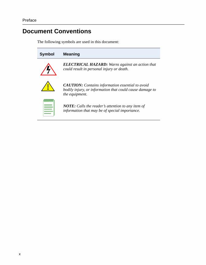
Document Conventions
The following symbols are used in this document:
Symbol Meaning
ELECTRICAL HAZARD: Warns against an action that could result in personal injury or death.
CAUTION: Contains information essential to avoid bodily injury, or information that could cause damage to the equipment.
NOTE: Calls the reader’s attention to any item of information that may be of special importance.
NOTE
Preface
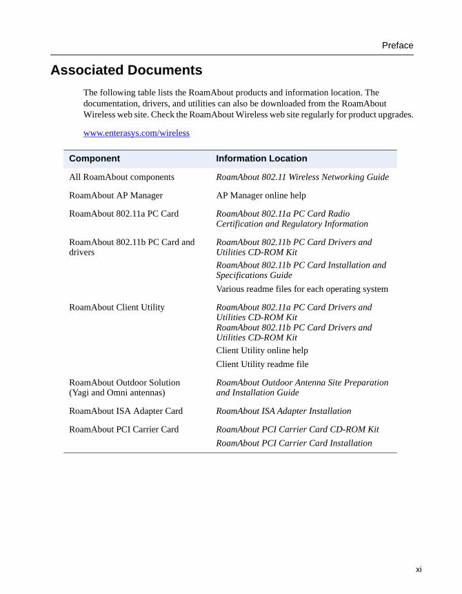
Associated Documents
The following table lists the RoamAbout products and information location. The documentation, drivers, and utilities can also be downloaded from the RoamAbout Wireless web site. Check the RoamAbout Wireless web site regularly for product upgrades.
www.enterasys.com/wireless
Component Information Location
All RoamAbout components RoamAbout 802.11 Wireless Networking Guide
RoamAbout AP Manager AP Manager online help
RoamAbout 802.11a PC Card RoamAbout 802.11a PC Card Radio Certification and Regulatory Information
RoamAbout 802.11b PC Card and drivers
RoamAbout 802.11b PC Card Drivers and Utilities CD-ROM Kit
RoamAbout 802.11b PC Card Installation and Specifications Guide
Various readme files for each operating system
RoamAbout Client Utility RoamAbout 802.11a PC Card Drivers and Utilities CD-ROM Kit RoamAbout 802.11b PC Card Drivers and Utilities CD-ROM Kit
Client Utility online help
Client Utility readme file
RoamAbout Outdoor Solution (Yagi and Omni antennas)
RoamAbout Outdoor Antenna Site Preparation and Installation Guide
RoamAbout ISA Adapter Card RoamAbout ISA Adapter Installation
RoamAbout PCI Carrier Card RoamAbout PCI Carrier Card CD-ROM Kit
RoamAbout PCI Carrier Card Installation
xi

Preface
x
Getting Help
For additional support related to this device or document, contact Enterasys Networks using one of the following methods:
Before contacting Enterasys Networks for technical support, have the following information ready:
• Your Enterasys Networks service contract number
• A description of the failure
• A description of any action(s) already taken to resolve the problem
• The serial and revision numbers of all involved Enterasys Networks products in the network
• A description of your network environment (layout, cable type)
• Network load and frame size at the time of trouble (if known)
• The device history (for example, have you returned the device before, is this a recurring problem, etc.)
• Any previous Return Material Authorization (RMA) numbers
World Wide Web: www.enterasys.com/support
Phone: (603) 332-94001-800-872-8440 (toll-free in the U.S. and Canada)For the Enterasys Networks Support toll-free number in your country: www.enterasys.com/support/gtac-all.html
Internet mail: [email protected]
To send comments or suggestions concerning this document to the Technical Writing Department: [email protected]
Make sure to include the document Part Number in the email message.
ii
Chapter 1
Preparing for Installation
This chapter describes basic considerations for successfully installing the RoamAbout R2 hardware. Before installing the RoamAbout R2, you must complete the following tasks:
• If you have an existing Access Point 2000 and want to install the RoamAbout R2 in its place, refer to Upgrading from an Existing Access Point 2000 on page 3-2 for important information.
• Review the site requirements.
• Select the location to install the RoamAbout R2.
• Unpack the RoamAbout R2 and check the contents of the shipment.
If installing the RoamAbout R2 in a building-to-building configuration, refer to the RoamAbout Outdoor Antenna Site Preparation and Installation Guide for the proper antenna cabling and grounding procedures.
After you install the RoamAbout R2, refer to the RoamAbout 802.11 Wireless Networking Guide for configuration information.
1-1
Reviewing the Site Requirements
1
Reviewing the Site Requirements
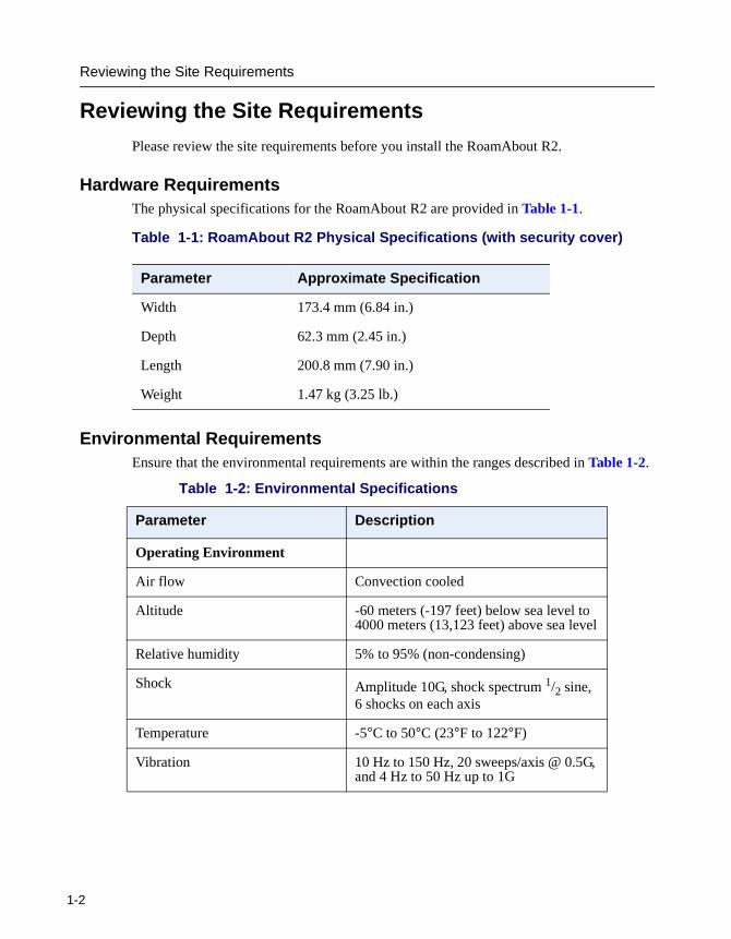
Please review the site requirements before you install the RoamAbout R2.
Hardware RequirementsThe physical specifications for the RoamAbout R2 are provided in Table 1-1.
Table 1-1: RoamAbout R2 Physical Specifications (with security cover)
Environmental RequirementsEnsure that the environmental requirements are within the ranges described in Table 1-2.
Parameter Approximate Specification
Width 173.4 mm (6.84 in.)
Depth 62.3 mm (2.45 in.)
Length 200.8 mm (7.90 in.)
Weight 1.47 kg (3.25 lb.)
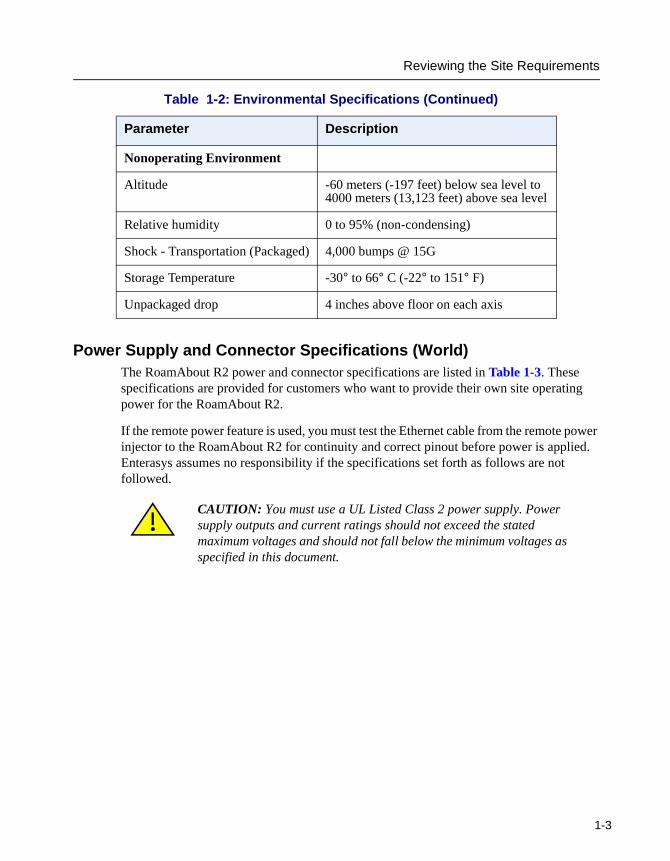
Table 1-2: Environmental Specifications
Parameter Description
Operating Environment
Air flow Convection cooled
Altitude -60 meters (-197 feet) below sea level to 4000 meters (13,123 feet) above sea level
Relative humidity 5% to 95% (non-condensing)
Shock Amplitude 10G, shock spectrum 1/2 sine, 6 shocks on each axis
Temperature -5°C to 50°C (23°F to 122°F)
Vibration 10 Hz to 150 Hz, 20 sweeps/axis @ 0.5G, and 4 Hz to 50 Hz up to 1G
-2
Reviewing the Site Requirements
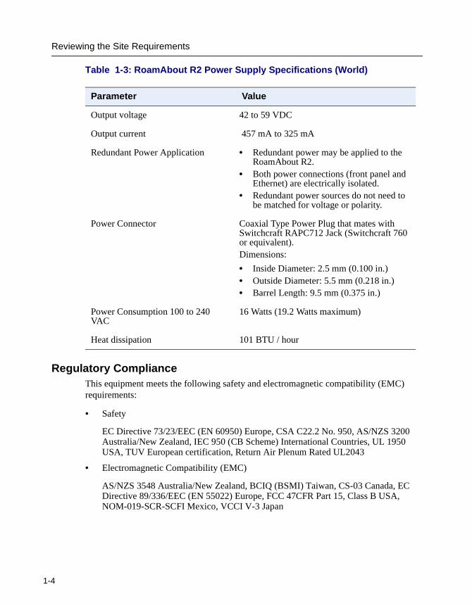
Power Supply and Connector Specifications (World)The RoamAbout R2 power and connector specifications are listed in Table 1-3. These specifications are provided for customers who want to provide their own site operating power for the RoamAbout R2.
If the remote power feature is used, you must test the Ethernet cable from the remote power injector to the RoamAbout R2 for continuity and correct pinout before power is applied. Enterasys assumes no responsibility if the specifications set forth as follows are not followed.
Nonoperating Environment
Altitude -60 meters (-197 feet) below sea level to 4000 meters (13,123 feet) above sea level
Relative humidity 0 to 95% (non-condensing)
Shock - Transportation (Packaged) 4,000 bumps @ 15G
Storage Temperature -30° to 66° C (-22° to 151° F)
Unpackaged drop 4 inches above floor on each axis
CAUTION: You must use a UL Listed Class 2 power supply. Power supply outputs and current ratings should not exceed the stated maximum voltages and should not fall below the minimum voltages as specified in this document.
Table 1-2: Environmental Specifications (Continued)
Parameter Description
1-3
Reviewing the Site Requirements
1
Table 1-3: RoamAbout R2 Power Supply Specifications (World)
Regulatory ComplianceThis equipment meets the following safety and electromagnetic compatibility (EMC) requirements:
• Safety
EC Directive 73/23/EEC (EN 60950) Europe, CSA C22.2 No. 950, AS/NZS 3200 Australia/New Zealand, IEC 950 (CB Scheme) International Countries, UL 1950 USA, TUV European certification, Return Air Plenum Rated UL2043
• Electromagnetic Compatibility (EMC)
AS/NZS 3548 Australia/New Zealand, BCIQ (BSMI) Taiwan, CS-03 Canada, EC Directive 89/336/EEC (EN 55022) Europe, FCC 47CFR Part 15, Class B USA, NOM-019-SCR-SCFI Mexico, VCCI V-3 Japan
Parameter Value
Output voltage 42 to 59 VDC
Output current 457 mA to 325 mA
Redundant Power Application • Redundant power may be applied to the RoamAbout R2.
• Both power connections (front panel and Ethernet) are electrically isolated.
• Redundant power sources do not need to be matched for voltage or polarity.
Power Connector Coaxial Type Power Plug that mates with Switchcraft RAPC712 Jack (Switchcraft 760 or equivalent).Dimensions:
• Inside Diameter: 2.5 mm (0.100 in.)• Outside Diameter: 5.5 mm (0.218 in.)• Barrel Length: 9.5 mm (0.375 in.)
Power Consumption 100 to 240 VAC
16 Watts (19.2 Watts maximum)
Heat dissipation 101 BTU / hour
-4
Unpacking and Inspecting
Unpacking and Inspecting
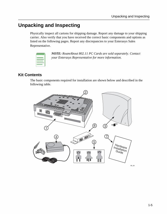
Physically inspect all cartons for shipping damage. Report any damage to your shipping carrier. Also verify that you have received the correct basic components and options as listed on the following pages. Report any discrepancies to your Enterasys Sales Representative.
Kit ContentsThe basic components required for installation are shown below and described in the following table.
NOTE: RoamAbout 802.11 PC Cards are sold separately. Contact your Enterasys Representative for more information.
�
�
�����
�
����� ���������������
�
�
�
�
1-5
Unpacking and Inspecting
1
RoamAbout R2
Verify that the following components shipped with your RoamAbout R2:
PC Card
The RoamAbout R2 supports both the RoamAbout 802.11a and 802.11b PC Cards, and their variants. To determine which PC Card is needed for your configuration, refer to the RoamAbout 802.11 Certification and Regulatory Information document available on the Enterasys Networks web site at: www.enterasys.com/wireless
There is a separate certification document for the 802.11a and 802.11b PC Cards. The RoamAbout PC Cards are sold separately. Contact your Enterasys sales representative for more information.
No. Description Part Number
1, 2 RoamAbout R2 (with wall/ceiling bracket) RBTR2-AB (1 slot, not shown) or RBTR2-AZ (2 slots)
3 Security Cover with key 8020216
4 Power Supply (100-240 VAC) 5652054-XX
5 International connector kit for the Power Supply (100-240 VAC)
5601013-Kit
6 Remote Power Injector 8917544-05
7 RoamAbout R2 Wireless Access Platform Installation Guide
9033683-XX
-6
Unpacking and Inspecting
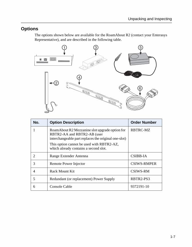
OptionsThe options shown below are available for the RoamAbout R2 (contact your Enterasys Representative), and are described in the following table.
No. Option Description Order Number
1 RoamAbout R2 Mezzanine slot upgrade option for RBTR2-AA and RBTR2-AB (user interchangeable part replaces the original one-slot)
This option cannot be used with RBTR2-AZ, which already contains a second slot.
RBTRC-MZ
2 Range Extender Antenna CSIBB-IA
3 Remote Power Injector CSIWS-RMPER
4 Rack Mount Kit CSIWS-RM
5 Redundant (or replacement) Power Supply RBTR2-PS3
6 Console Cable 9372191-10
�
�
� �
��
1-7
Testing the Coverage Area
1
Testing the Coverage Area
Enterasys Networks recommends that you test the coverage area before you permanently install the RoamAbout R2. The coverage area is where wireless clients can be physically located and still connect to the RoamAbout R2. Coverage area is determined by a number of factors, including the speed of the RoamAbout PC Card, physical obstructions, and noise levels.
If possible, temporarily connect the RoamAbout R2 and use the RoamAbout utilities described in the RoamAbout 802.11 Wireless Networking Guide to determine the actual coverage area. Using these tools can help you determine the best place to mount the RoamAbout R2.
Antenna Information
This document contains only installation information for the indoor antenna. If you are planning to use an outdoor antenna refer to the RoamAbout Outdoor Antenna Site Preparation and Installation Guide for Regulatory information, FCC requirements, and detailed procedures to install outdoor antennas.
-8
Chapter 2
Cabling and Wiring
This chapter presents detailed step-by-step procedures to select, configure, and install the correct power, cabling, and wiring for your RoamAbout R2.
CAUTION: The Enterasys 5652054-xx International DC Power Supply (ships with the RoamAbout R2) and the RBTR2-PS3 Redundant DC Power Supply have overload protection. If an overload occurs because of miswiring or some other fault, the power supply voltage folds back to help protect the power supply, the site wiring, and the RoamAbout R2 from damage.
2-1
Selecting a Power Configuration
2
Selecting a Power Configuration
The power configurations available for the RoamAbout R2 include local power, remote power, and redundant power.
Local Power ConfigurationIn the local power configuration, the RoamAbout R2 receives operating power directly from one local source (such as a power supply connected to a nearby wall outlet). The output plug of the power supply is connected directly into the RoamAbout R2 chassis-mounted power connector.
Remote Power ConfigurationIn the remote power configuration, the RoamAbout R2 receives operating power over the Ethernet cable from one remote source (such as a power supply installed in the wiring closet or other remote location). This option requires installing the remote power injector in the same location as the power supply. The output of the power supply is connected to the remote power injector. The Ethernet interface cable also plugs into the remote power injector. Another Ethernet cable is connected between the injector and the RoamAbout R2 to provide input/output signals and power.
Enterasys offers an optional rack mount kit that allows installation of up to three remote power injectors into one standard rack-mount panel. See Rack Mount Kit Installation on page 2-5 for more information.
Redundant Power ConfigurationThe RoamAbout R2 can be connected to an independent source of local power and to an independent source of remote power. If one of these power sources goes down, the RoamAbout R2 continues uninterrupted operation with power received from the other (redundant) power source.
CAUTION: Label the remote power injector cable at the opposite end from the power injector (RoamAbout R2 or wall jack) to ensure that this cable is not connected to another device. The procedures in Chapter 3 offer sample text.
-2
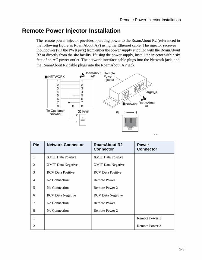
Remote Power Injector Installation
Remote Power Injector Installation
The remote power injector provides operating power to the RoamAbout R2 (referenced in the following figure as RoamAbout AP) using the Ethernet cable. The injector receives input power (via the PWR jack) from either the power supply supplied with the RoamAbout R2 or directly from the site facility. If using the power supply, install the injector within six feet of an AC power outlet. The network interface cable plugs into the Network jack, and the RoamAbout R2 cable plugs into the RoamAbout AP jack.
Pin Network Connector RoamAbout R2 Connector
Power Connector
1 XMIT Data Positive XMIT Data Positive
2 XMIT Data Negative XMIT Data Negative
3 RCV Data Positive RCV Data Positive
4 No Connection Remote Power 1
5 No Connection Remote Power 2
6 RCV Data Negative RCV Data Negative
7 No Connection Remote Power 1
8 No Connection Remote Power 2
1 Remote Power 1
2 Remote Power 2
��������
��������
���������� ����!
"�"�
"�
�
�#$�
%�$&�'����()���
(#
#$�
����!
�����
#�������������������
������#��� �*�+��
����()���(#
2-3
Remote Power Injector Installation
2
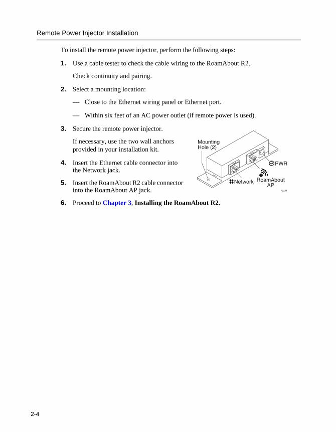
To install the remote power injector, perform the following steps:
1. Use a cable tester to check the cable wiring to the RoamAbout R2.
Check continuity and pairing.
2. Select a mounting location:
— Close to the Ethernet wiring panel or Ethernet port.
— Within six feet of an AC power outlet (if remote power is used).
3. Secure the remote power injector.
If necessary, use the two wall anchors provided in your installation kit.
4. Insert the Ethernet cable connector into the Network jack.
5. Insert the RoamAbout R2 cable connector into the RoamAbout AP jack.
6. Proceed to Chapter 3, Installing the RoamAbout R2.
#$�
����!
,������-�����.�/
�����
����()���(#
-4
Rack Mount Kit Installation
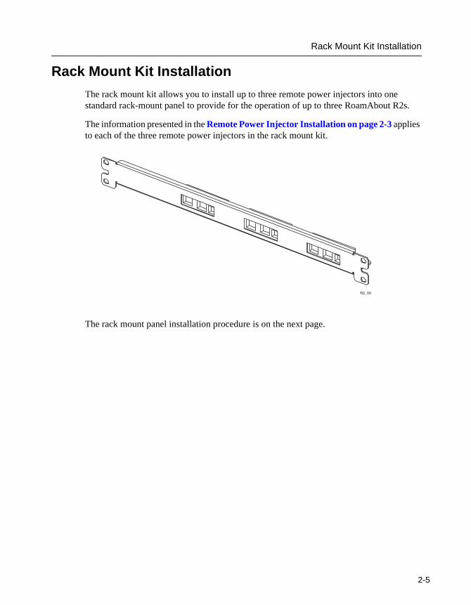
Rack Mount Kit Installation
The rack mount kit allows you to install up to three remote power injectors into one standard rack-mount panel to provide for the operation of up to three RoamAbout R2s.
The information presented in the Remote Power Injector Installation on page 2-3 applies to each of the three remote power injectors in the rack mount kit.
The rack mount panel installation procedure is on the next page.
�����
2-5

Rack Mount Kit Installation
2
To install the rack mount kit, perform the following steps.
1. Use a cable tester to check the cable wiring to each RoamAbout R2.
Check continuity and pairing.
2. Select a mounting location:
— Close to the Ethernet wiring panel.
— Within six feet of an AC power outlet (if remote power is used).
3. Install up to three remote power injectors within the rack mount panel.
Use the screws provided in the rack mount kit to secure each remote power injector to the rack mount panel.
4. Secure the rack mount panel to the rack using the screws provided in the kit.
5. Insert an Ethernet cable connector into the Network jack of one of the remote power injectors.
6. Insert the RoamAbout R2 cable connector into the RoamAbout AP jack of the same remote power injector.
7. Repeat Steps 5 and 6 for each RoamAbout R2.
8. Proceed to Chapter 3, Installing the RoamAbout R2.
-6
Power Supply Installation
Power Supply Installation
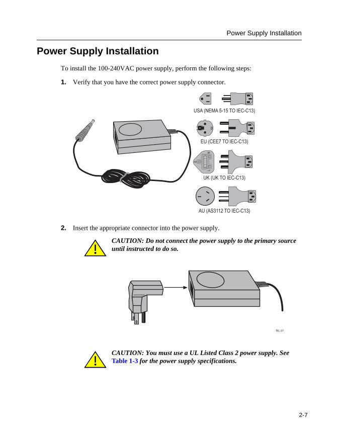
To install the 100-240VAC power supply, perform the following steps:
1. Verify that you have the correct power supply connector.
2. Insert the appropriate connector into the power supply.
CAUTION: Do not connect the power supply to the primary source until instructed to do so.
CAUTION: You must use a UL Listed Class 2 power supply. See Table 1-3 for the power supply specifications.
�������������� � ���
���������� � ���
�
��
���� ������� � ���
������������������ � ���
�����
2-7
Ethernet Wiring Configuration
2
Ethernet Wiring Configuration
The RoamAbout R2 supports the 100BaseT Ethernet cabling standard with auto negotiation. If you have an existing 10BaseT Ethernet cable in place, you can connect the cable directly to the RoamAbout R2. You can also connect the Ethernet cable to the remote power injector, then connect the remote power injector to the RoamAbout R2.
The RoamAbout R2 supports auto-crossover detection. You can use straight-through or crossover cables for Ethernet connectivity.
CAT 5 Cabling Standards
There are four common CAT 5 Cabling Standards. Three of these, EIA 568A, EIA 568B, and EIA 356A, are recommended for RoamAbout R2 installations. The fourth standard, USOC, has advantages when dealing with telephone wiring but is strongly not recommended for use in data applications.
All CAT 5 information presented here also applies to CAT 3. However, CAT 3 is not recommended for 100BaseT Ethernet connections.
• If new wiring is installed for the RoamAbout R2, it is extremely important to know which standard was used to install the existing wiring.
• It is also important that new wiring complies with and is tested to CAT 5 Cabling Standards. Miswiring of data pairs can result in a faulty Ethernet connection and possible power problems.
• In the event of data or power miswiring when using the RoamAbout R2 power supply and remote power, the power supply folds back and does not damage the R2.
• If you are not using a RoamAbout R2 power supply, miswiring of data or power may damage the R2. Use care when installing the wiring for the Remote Power feature.
CAUTION: If you are installing the RoamAbout R2 in Air Space or a Plenum environment, the RoamAbout R2 must only be powered by the Remote Power Splice through a Plenum-rated CAT-5 cable. The Remote Power Splice, Power Supply, and Security Cover do not meet Plenum requirements and must be kept out of Plenum areas.
Before you install the RoamAbout R2 in Air Space or a Plenum environment, you should check with your local building and electrical inspector for local regulations concerning electrical code requirements for Plenum installations.
-8

Chapter 3
Installing the RoamAbout R2
This chapter provides the procedures to install the RoamAbout R2 and its options. It also provides the basic configurations using the console, RoamAbout AP Manager, Telnet, and R2 Web Management. Refer to the Roamabout 802.11 Wireless Networking Guide for additional configuration information.
Make sure the site primary power for the RoamAbout R2 conforms to the specifications detailed in Chapter 2, Cabling and Wiring.
If you are using the AP Manager to configure the RoamAbout R2s with IP addresses, you should start the AP Manager BEFORE applying power to each RoamAbout R2. Upon power-up, each RoamAbout R2 automatically sends a BootP request.
If you plan to use the RoamAbout AP Manager program, write down the MAC address listed on the side of the RoamAbout R2. For a LAN-to-LAN configuration, also write down the MAC address on the back of the PC Card, which is the wireless MAC address.
NOTE: This document contains only installation information for the indoor antenna. If you are planning to use an outdoor antenna, refer to the RoamAbout Outdoor Antenna Site Preparation and Installation Guide for Regulatory information, FCC requirements, and detailed procedures to install outdoor antennas. The RoamAbout Outdoor Antenna Site Preparation and Installation Guide can be downloaded from www.enterasys.com/wireless.
3-1
Upgrading from an Existing Access Point 2000
3
Upgrading from an Existing Access Point 2000
You cannot interchange the Access Point 2000 with the RoamAbout R2 without replacing the power supplies and, if applicable, the power injector and redundant power supply. You must use the power supply, power injector, and the redundant power supply shipped with the RoamAbout R2.
• You must replace the Access Point 2000 power supply (5652041-xx or 5652042-xx) with the RoamAbout R2 power supply (5652054-xx) at the RoamAbout R2.
• You must replace the Access Point 2000 redundant power supply (5652042-xx), on the wired side, with the RoamAbout R2 power supply (5652054-xx).
To determine if your Access Point contains a redundant power supply:
a) Remove the power supply from the Access Point.
b) If there is still power, you will need to locate the redundant power supply on the wired side. Replace it with the RoamAbout R2 power supply (5652054-xx).
• You must replace the following Access Point power injectors:
— 8917544-01— 8917544-02— 8917544-03
with 8917544-05 (preferred) or 8917544-04.
CAUTION: If you have an existing Access Point 2000 and want to install the RoamAbout R2 in its place, please refer to the following important information.
-2
Wall/Ceiling Outlet Box Installation
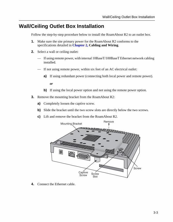
Wall/Ceiling Outlet Box Installation
Follow the step-by-step procedure below to install the RoamAbout R2 to an outlet box.
1. Make sure the site primary power for the RoamAbout R2 conforms to the specifications detailed in Chapter 2, Cabling and Wiring.
2. Select a wall or ceiling outlet:
— If using remote power, with internal 10BaseT/100BaseT Ethernet network cabling installed.
— If not using remote power, within six feet of an AC electrical outlet:
a) If using redundant power (connecting both local power and remote power).
or
b) If using the local power option and not using the remote power option.
3. Remove the mounting bracket from the RoamAbout R2:
a) Completely loosen the captive screw.
b) Slide the bracket until the two screw slots are directly below the two screws.
c) Lift and remove the bracket from the RoamAbout R2.
4. Connect the Ethernet cable.
����0�,������-�1�+!��
��2��0�3+�� 3+��
3���
3+��
3-3
Wall/Ceiling Outlet Box Installation
3
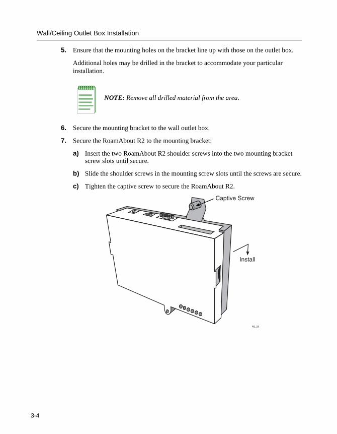
5. Ensure that the mounting holes on the bracket line up with those on the outlet box.
Additional holes may be drilled in the bracket to accommodate your particular installation.
NOTE: Remove all drilled material from the area.
6. Secure the mounting bracket to the wall outlet box.
7. Secure the RoamAbout R2 to the mounting bracket:
a) Insert the two RoamAbout R2 shoulder screws into the two mounting bracket screw slots until secure.
b) Slide the shoulder screws in the mounting screw slots until the screws are secure.
c) Tighten the captive screw to secure the RoamAbout R2.
�����
��2��0��3+��
������
-4
Wall/Ceiling Outlet Box Installation
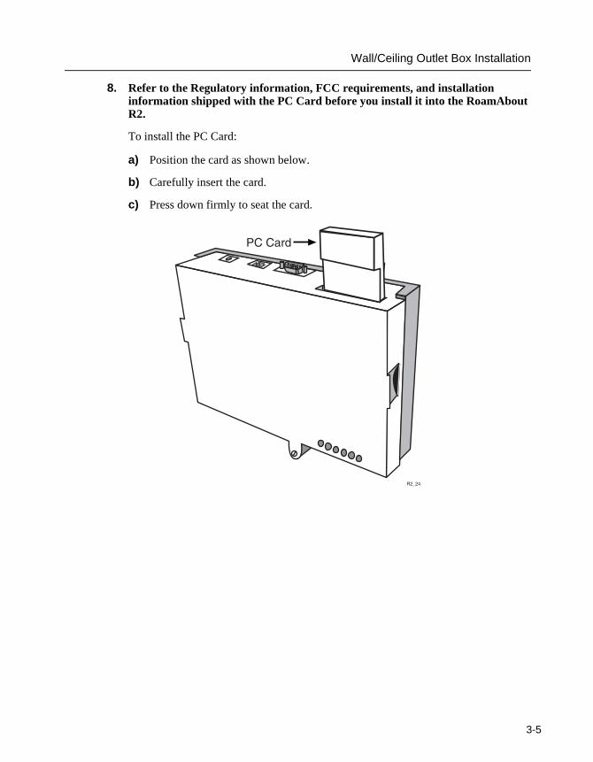
8. Refer to the Regulatory information, FCC requirements, and installation information shipped with the PC Card before you install it into the RoamAbout R2.
To install the PC Card:
a) Position the card as shown below.
b) Carefully insert the card.
c) Press down firmly to seat the card.
�����
#����
3-5
Wall/Ceiling Outlet Box Installation
3
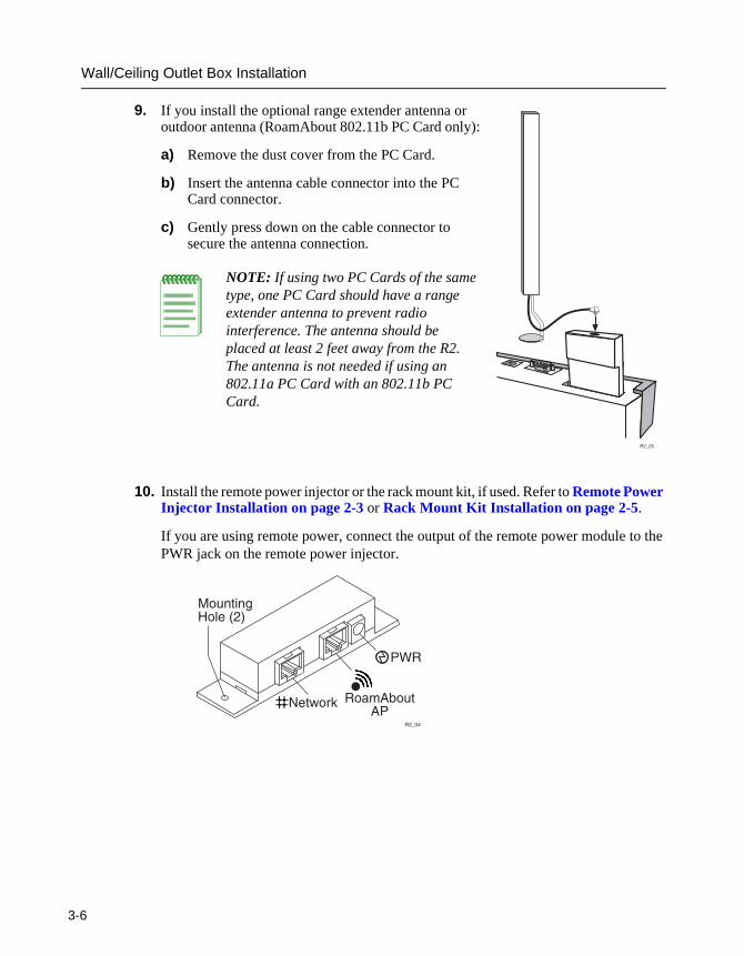
9. If you install the optional range extender antenna or outdoor antenna (RoamAbout 802.11b PC Card only):
a) Remove the dust cover from the PC Card.
b) Insert the antenna cable connector into the PC Card connector.
c) Gently press down on the cable connector to secure the antenna connection.
10. Install the remote power injector or the rack mount kit, if used. Refer to Remote Power Injector Installation on page 2-3 or Rack Mount Kit Installation on page 2-5.
If you are using remote power, connect the output of the remote power module to the PWR jack on the remote power injector.
NOTE: If using two PC Cards of the same type, one PC Card should have a range extender antenna to prevent radio interference. The antenna should be placed at least 2 feet away from the R2. The antenna is not needed if using an 802.11a PC Card with an 802.11b PC Card.
�����
#$�
����!
,������-�����.�/
�����
����()���(#
-6
Wall/Ceiling Outlet Box Installation
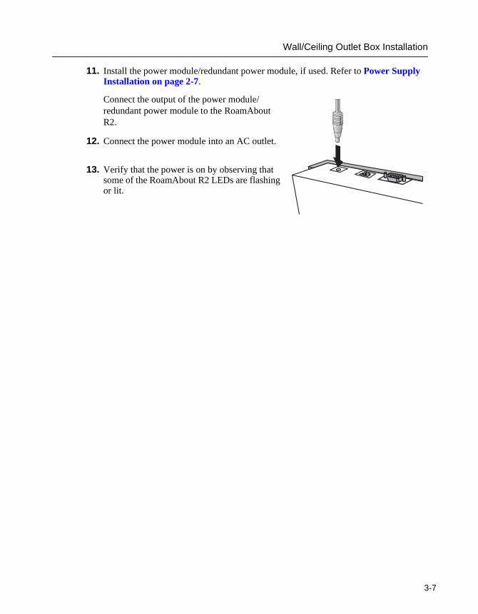
11. Install the power module/redundant power module, if used. Refer to Power Supply Installation on page 2-7.
Connect the output of the power module/redundant power module to the RoamAbout R2.
12. Connect the power module into an AC outlet.
13. Verify that the power is on by observing that some of the RoamAbout R2 LEDs are flashing or lit.
3-7

Wall/Ceiling Outlet Box Installation
3
14. Secure the cover:
a) Position the cover over the RoamAbout R2.
b) Make sure the cover clears the PC Card (and the optional antenna cable).
c) Push the cover down until all four snaps are secured.
d) Lock the cover in place using the key.
�����
3��2�
'�4�����
-8

Surface Wallmount Installation
Surface Wallmount Installation
Follow the step-by-step procedure below to install the RoamAbout R2 on the surface of a wall, cubical wall, vertical support structure, or ceiling.
1. Make sure the site primary power for the RoamAbout R2 conforms to the specifications detailed in Chapter 2, Cabling and Wiring.
2. Select the optimum mounting location:
— With easy access for inspection and service.
— If using remote power, close to the 10BaseT/100BaseT Ethernet network cable connector.
— If not using remote power, within six feet of an AC electrical outlet:
a) If using redundant power (connecting both local power and remote power).
or
b) If using the local power option and not using the remote power option.
3-9
Surface Wallmount Installation
3
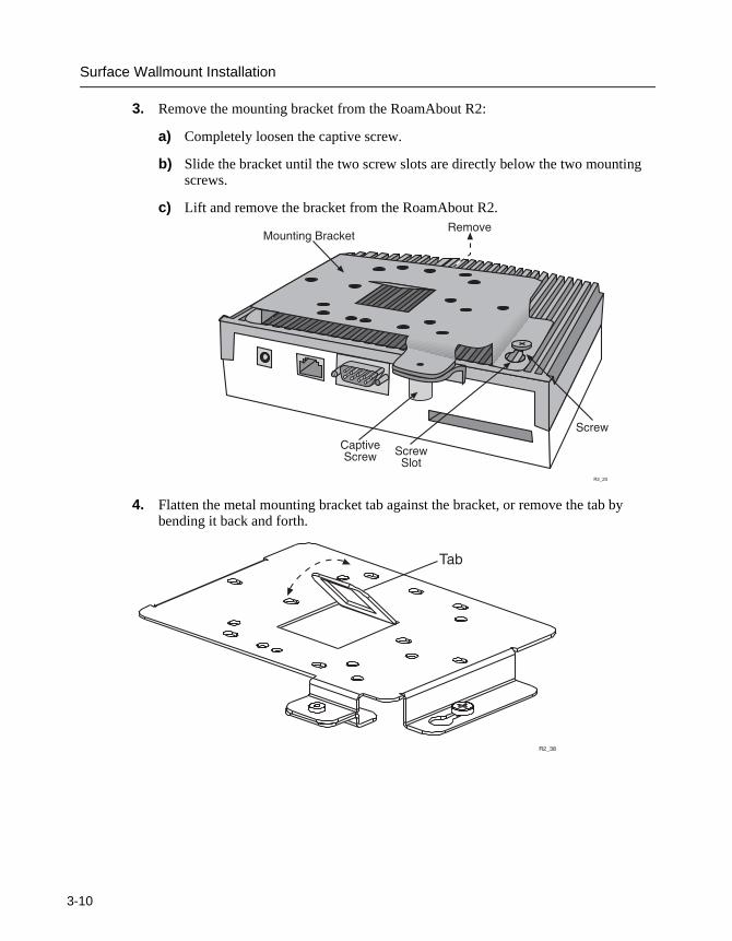
3. Remove the mounting bracket from the RoamAbout R2:
a) Completely loosen the captive screw.
b) Slide the bracket until the two screw slots are directly below the two mounting screws.
c) Lift and remove the bracket from the RoamAbout R2.
4. Flatten the metal mounting bracket tab against the bracket, or remove the tab by bending it back and forth.
����0�
�����
,������-�1�+!��
��2��0�3+�� 3+��
3���
3+��
��)
�����
-10

Surface Wallmount Installation
5. Secure the mounting bracket to the wall:
a) Locate at least two mounting holes/slots on the mounting bracket that line up with a wall stud.
b) Use two screws to secure the mounting bracket to the wall stud.
c) Use plastic anchors and screws, or self-anchoring screws to secure the mounting bracket to the wallboard.
NOTE: Additional holes may be drilled in the bracket to accommodate your particular installation. Remove all drilled material from the area.
MountingHoles/Slots
3-11
Surface Wallmount Installation
3
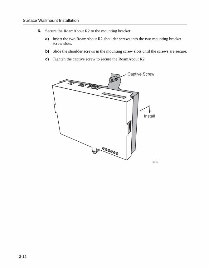
6. Secure the RoamAbout R2 to the mounting bracket:
a) Insert the two RoamAbout R2 shoulder screws into the two mounting bracket screw slots.
b) Slide the shoulder screws in the mounting screw slots until the screws are secure.
c) Tighten the captive screw to secure the RoamAbout R2.
�����
��2��0��3+��
������
-12
Surface Wallmount Installation
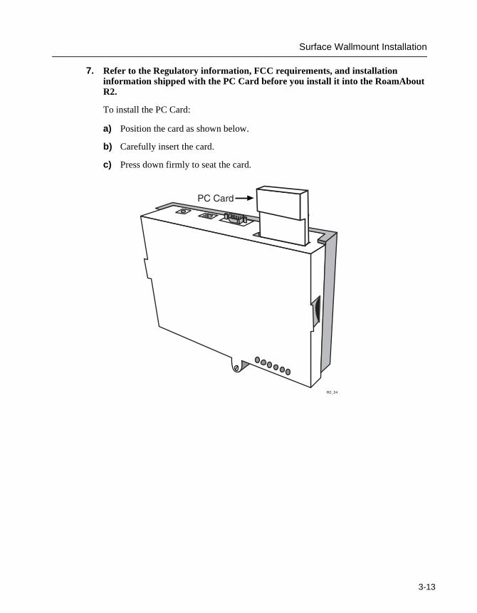
7. Refer to the Regulatory information, FCC requirements, and installation information shipped with the PC Card before you install it into the RoamAbout R2.
To install the PC Card:
a) Position the card as shown below.
b) Carefully insert the card.
c) Press down firmly to seat the card.
�����
#����
3-13
Surface Wallmount Installation
3
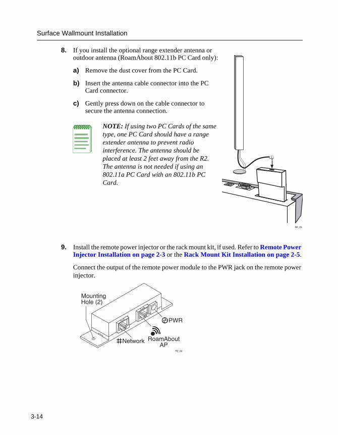
8. If you install the optional range extender antenna or outdoor antenna (RoamAbout 802.11b PC Card only):
a) Remove the dust cover from the PC Card.
b) Insert the antenna cable connector into the PC Card connector.
c) Gently press down on the cable connector to secure the antenna connection.
9. Install the remote power injector or the rack mount kit, if used. Refer to Remote Power Injector Installation on page 2-3 or the Rack Mount Kit Installation on page 2-5.
Connect the output of the remote power module to the PWR jack on the remote power injector.
NOTE: If using two PC Cards of the same type, one PC Card should have a range extender antenna to prevent radio interference. The antenna should be placed at least 2 feet away from the R2. The antenna is not needed if using an 802.11a PC Card with an 802.11b PC Card.
�����
#$�
����!
,������-�����.�/
�����
����()���(#
-14
Surface Wallmount Installation
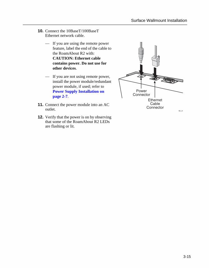
10. Connect the 10BaseT/100BaseT Ethernet network cable.
— If you are using the remote power feature, label the end of the cable to the RoamAbout R2 with: CAUTION: Ethernet cable contains power. Do not use for other devices.
— If you are not using remote power, install the power module/redundant power module, if used; refer to Power Supply Installation on page 2-7.
11. Connect the power module into an AC outlet.
12. Verify that the power is on by observing that some of the RoamAbout R2 LEDs are flashing or lit.
#��������+��
%�5������)��
�����+�������
3-15
Surface Wallmount Installation
3
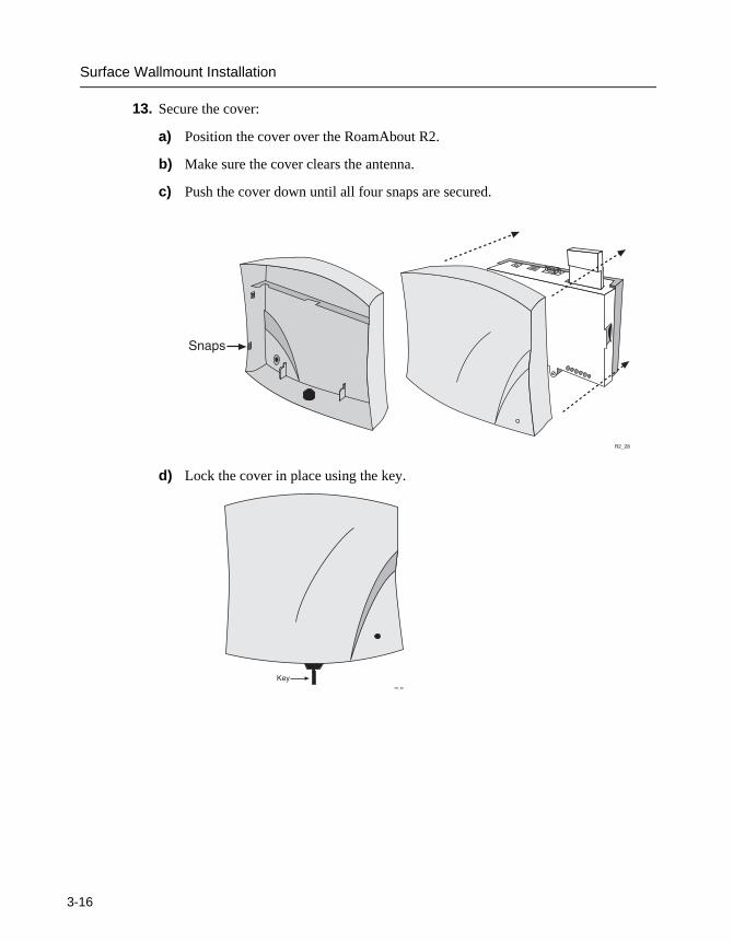
13. Secure the cover:
a) Position the cover over the RoamAbout R2.
b) Make sure the cover clears the antenna.
c) Push the cover down until all four snaps are secured.
d) Lock the cover in place using the key.
�����
3��2�
'�4�����
-16
Console Port Connection
Console Port Connection
You can manage the R2 using its console port, Telnet, SSH client, web management or the RoamAbout AP Manager. You do not need to use the console port if you use the RoamAbout AP Manager. If you use Telnet, SSH or Web Management, you will need to connect to the console port to set up the R2 IP address before you can access the R2. These management tools are described in the RoamAbout 802.11 Wireless Networking Guide.
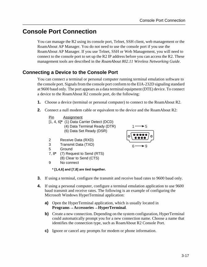
Connecting a Device to the Console PortYou can connect a terminal or personal computer running terminal emulation software to the console port. Signals from the console port conform to the EIA-232D signaling standard at 9600 baud only. The port appears as a data terminal equipment (DTE) device. To connect a device to the RoamAbout R2 console port, do the following:
1. Choose a device (terminal or personal computer) to connect to the RoamAbout R2.
2. Connect a null modem cable or equivalent to the device and the RoamAbout R2:
3. If using a terminal, configure the transmit and receive baud rates to 9600 baud only.
4. If using a personal computer, configure a terminal emulation application to use 9600 baud transmit and receive rates. The following is an example of configuring the Microsoft Windows HyperTerminal application:
a) Open the HyperTerminal application, which is usually located in Programs→Accessories→HyperTerminal.
b) Create a new connection. Depending on the system configuration, HyperTerminal could automatically prompt you for a new connection name. Choose a name that identifies the connection type, such as RoamAbout R2 Console Port.
c) Ignore or cancel any prompts for modem or phone information.
1 5
6 9LKG-8996-931-01
Pin Assignment[1, 4, 6]* (1) Data Carrier Detect (DCD)
(4) Data Terminal Ready (DTR) (6) Data Set Ready (DSR)
2 Receive Data (RXD)3 Transmit Data (TXD)5 Ground7, 8* (7) Request to Send (RTS)
(8) Clear to Send (CTS)9 No connect
* [1,4,6] and [7,8] are tied together.
3-17
Console Port Connection
3
d) In a Connect Using or similar field, select the port that is connected to the RoamAbout R2, such as COM1.
e) In the Port Settings window, enter:
— Bits per second: 9600
— Data bits: 8
— Parity: None
— Stop Bits: 1
— Flow Control: None
To connect to the console port at a later date, open HyperTerminal and select File→Open to open the RoamAbout R2 Console Port connection.
5. Press <Enter> a few times until the RoamAbout R2 Installation Menu is displayed. The installation menu allows you to display and modify various RoamAbout R2 and wireless networking parameters.
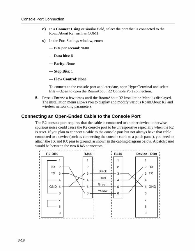
Connecting an Open-Ended Cable to the Console PortThe R2 console port requires that the cable is connected to another device; otherwise, spurious noise could cause the R2 console port to be unresponsive especially when the R2 is reset. If you plan to connect a cable to the console port but not always have that cable connected to a device (such as connecting the console cable to a patch panel), you need to attach the TX and RX pins to ground, as shown in the cabling diagram below. A patch panel would be between the two RJ45 connectors.
������ ����������
�
�
�
�
�
�
�
�
�
�
�
�
�
�
�
�
�
�
�6
�6
� 7
1��+!
��
����
8�����
�6
�6
� 7
�� �
�
�
�
�
�
�
�� �
�
�
�
�
�
�
-18
Verifying the Operation of the RoamAbout R2
Verifying the Operation of the RoamAbout R2
The RoamAbout R2 runs a series of self-tests on power-up and reports status using its LEDs. The diagnostics take several seconds to complete after power-up. Table 3-1 describes the LEDs. If the RoamAbout R2 LEDs indicate an error, verify that you have correctly installed the RoamAbout R2. Table 3-2 describes the patterns, the most likely causes, and possible corrective actions. If the RoamAbout R2 still fails, refer to the RoamAbout 802.11 Wireless Networking Guide.
The Reload/Reset button is used to download a new firmware image to the RoamAbout R2, and to reset the RoamAbout R2 to the factory defaults. You need to write down the MAC address (in the MAC ADD box) for use when configuring the RoamAbout R2.
Once the RoamAbout R2 is installed and powered on, refer to the RoamAbout 802.11 Wireless Networking Guide to set the RoamAbout R2 parameters.
3-19
Verifying the Operation of the RoamAbout R2
3
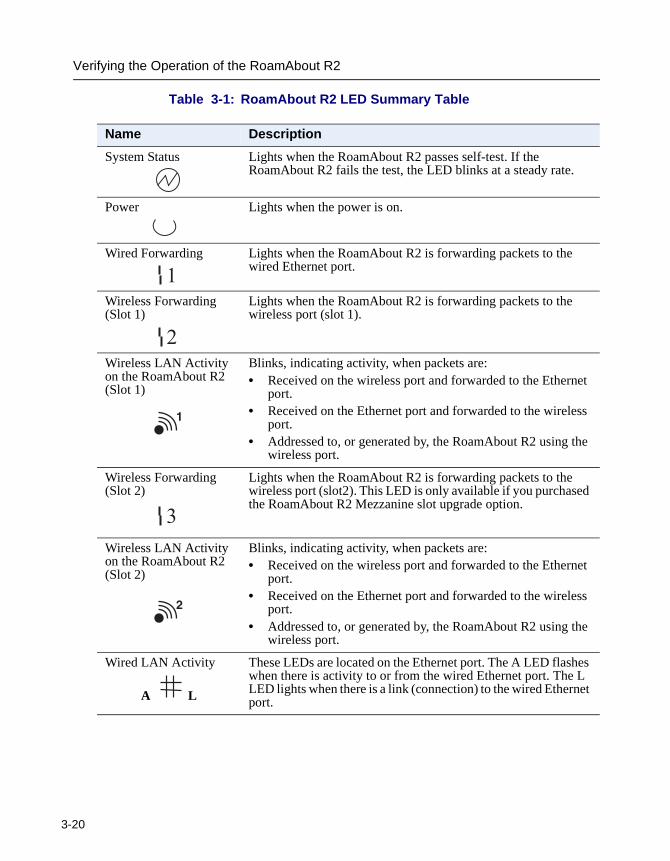
Table 3-1: RoamAbout R2 LED Summary Table
Name Description
System Status Lights when the RoamAbout R2 passes self-test. If the RoamAbout R2 fails the test, the LED blinks at a steady rate.
Power Lights when the power is on.
Wired Forwarding Lights when the RoamAbout R2 is forwarding packets to the wired Ethernet port.
Wireless Forwarding (Slot 1)
Lights when the RoamAbout R2 is forwarding packets to the wireless port (slot 1).
Wireless LAN Activity on the RoamAbout R2 (Slot 1)
Blinks, indicating activity, when packets are:• Received on the wireless port and forwarded to the Ethernet
port.• Received on the Ethernet port and forwarded to the wireless
port.• Addressed to, or generated by, the RoamAbout R2 using the
wireless port.
Wireless Forwarding (Slot 2)
Lights when the RoamAbout R2 is forwarding packets to the wireless port (slot2). This LED is only available if you purchased the RoamAbout R2 Mezzanine slot upgrade option.
Wireless LAN Activity on the RoamAbout R2 (Slot 2)
Blinks, indicating activity, when packets are:• Received on the wireless port and forwarded to the Ethernet
port.• Received on the Ethernet port and forwarded to the wireless
port.• Addressed to, or generated by, the RoamAbout R2 using the
wireless port.
Wired LAN Activity
A L
These LEDs are located on the Ethernet port. The A LED flashes when there is activity to or from the wired Ethernet port. The L LED lights when there is a link (connection) to the wired Ethernet port.
�
�
�
�
�
-20
Verifying the Operation of the RoamAbout R2
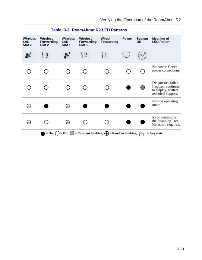
Table 3-2: RoamAbout R2 LED Patterns
Wireless LAN Slot 2
Wireless Forwarding Slot 2
Wireless LAN Slot 1
Wireless Forwarding Slot 1
Wired Forwarding
Power System OK
Meaning of LED Pattern
No power. Check power connections.
Diagnostics failed. If pattern continues to display, contact technical support.
Normal operating mode.
R2 is waiting for the Spanning Tree. No action required.
= On, = Off, = Constant blinking, = Random blinking, = Any state
� � � � �
3-21

Chapter 4
Configuring the RoamAbout R2
This chapter provides the basic procedures to configure the RoamAbout R2 for a wireless infrastructure network (where wireless clients access the LAN via the R2). Refer to the RoamAbout 802.11 Wireless Networking Guide to configure the R2 for a LAN-to-LAN network or for information on advanced configuration procedures, such as security settings.
The RoamAbout R2 provides a number of interfaces, but only the console port or AP Manager allows you to initially configure the R2 with an IP address. For more information about all the interfaces, refer to the RoamAbout 802.11 Wireless Networking Guide.
RoamAbout R2 MAC Addresses
The RoamAbout R2 has the following MAC addresses:
• One MAC address for the wired Ethernet interface, which is printed on the AP.
• One MAC address for each RoamAbout PC Card installed in the AP, which is printed on a label on the back side of the card.
• One MAC address for the Spanning Tree. This MAC address is the wired MAC address plus 10 hex. For example, if the RoamAbout R2 MAC address is xx-xx-xx-xx-xx-40, the Spanning Tree MAC address will be xx-xx-xx-xx-xx-50.
If using SNMP, you may see additional MAC addresses, starting with the MAC address printed on the AP. These additional 30 MAC addresses are used internally and do not generate network traffic.
4-1
Using the Console Port
4
Using the Console Port
To connect a device to the console port, follow the instructions in Console Port Connection on page 3-17. Perform the following to use the console interface:
• Use your arrow keys to navigate through the screens.
• Press your Enter (or Return) key to activate a data entry field.
• Press the space bar to toggle a multiple choice field.
• Select Apply to check the configuration changes before saving them.
• Select Save before you Reset, Reload or Exit out of the console to save the configuration changes in each screen.
To manage the RoamAbout R2 with the console port, do the following:
1. Press the <Return> key at the terminal that is connected to the RoamAbout R2 console port until the Main Menu displays. If using a computer, start the terminal emulation program and connect to the console port. You are prompted for a username and password. The username is admin and the default password is password.
2. Choose Network Configuration from the Main Menu.
3. Enter the IP address, subnet mask, and default gateway.
4. Choose Save.
5. Choose Wireless Configuration from the Main Menu, then choose Set/Show Wireless Configuration.
6. At the top of the screen, select the radio slot (1 or 2) to configure.
7. Enter the name of the wireless network.
8. Enter a channel. The channels vary, depending on country regulations. In a wireless client configuration (Workgroup bridge mode) with multiple APs, adjacent APs should be set to different channels that are at least five channels apart.
9. Enter a station name. This name is displayed when clients run the RoamAbout Client Utility. Each RoamAbout R2 should have a unique station name.
10. Set the Reset Option to Reset Card if necessary (the default setting).
11. Choose Save.
NOTE: If your screen remains blank after 3 seconds, press the Ctrl and L keys together. If the screen still remains blank, shut down the terminal emulation program and then restart it.
-2
Using the RoamAbout AP Manager
Using the RoamAbout AP Manager
To manage the R2 using the AP Manager, you need the R2’s wired MAC address.
1. At the computer with AP Manager installed, start the AP Manager by clicking the Start button on the desktop and selecting Programs→RoamAbout→AP Manager.
2. Click on the Setup/Add New AP button to setup/add a RoamAbout R2. (Or, select File→Open from the menu bar to open the appropriate group of RoamAbout R2s, or to add to an existing managed list.)
3. When prompted, click Yes to provide an IP address.
4. Enter the RoamAbout R2’s wired MAC address (printed on the side of the RoamAbout R2 under the plastic cover).
5. Assign the RoamAbout R2 a valid IP address for your network.
6. Enter the SNMPv3 Authentication and Privacy Passwords, or accept the defaults.
— The default Authentication Password is password.
— The default Privacy Password is password.
— The password is case-sensitive and must be a minimum of eight ASCII characters.
7. If necessary, change the default gateway and subnet mask. Click OK when completed.
8. In the Identification dialog box, enter the text to describe the RoamAbout R2. Click the Help button for details. Click OK when completed.
9. In the Wireless Parameters dialog box, enter the name of the wireless network.
10. Enter a channel. If there are other RoamAbout APs whose coverage areas overlap, make sure that the PC Cards use a different channel. If using a RoamAbout 802.11b PC Card, enter a channel that is at least five channels apart from the other APs.
11. Enter a station name. The station name is displayed when clients run the RoamAbout Client Utility. Each RoamAbout R2 should have a unique station name.
12. Select File→Save from the main window to save the configuration changes to a .cfg file. You are prompted for a password. The password must be a minimum of eight ASCII characters and is case-sensitive. This password prevents unauthorized access to the RoamAbout R2 configuration.
NOTE: The OK button remains grayed out until you enter text.
.
4-3

Appendix F
Upgrade and Reset
This appendix describes how to upgrade the RoamAbout R2 firmware using the console port, AP Manager, or the web-based management. It also describes how to reset the R2 to all factory defaults.
Check the Enterasys Networks Wireless web site for the latest RoamAbout AP Manager and firmware. Go to www.enterasys.com/wireless and click on the Software Download Library to download the latest AP Manager and RoamAbout R2 firmware. The AP Manager contains the firmware and BootROM image files. Refer to the AP Manager release notes for the instructions to install the AP Manager.
CAUTION: If the power is interrupted during the upgrade or reset back to factory defaults process, the image in your device will become corrupt. Do not turn off or perform any action that can cause power loss during an upgrade.
F-1
Upgrade Firmware
F
Upgrade Firmware
Using the RoamAbout R2 Console PortFollow this procedure to upgrade the R2 from the console port. This procedure also applies if accessing the R2 using Telnet or an SSH client.
1. Manually launch NetRider Loader, go to the Program Files/RoamAbout/Manager directory and double-click on the Loader.exe file, or start the TFTP server that you want to use.
2. Choose Reset/Upgrade from the RoamAbout R2 Console Main menu.
3. Choose Upgrade Flash.
4. Enter the latest G*.Z file for firmware upgrades, or B*.BIN file for BootROM upgrades in the Image file path.
5. Enter the TFTP Server IP address of the system running NetRider Loader, or your TFTP server’s IP address.
6. Press the space bar in the Download Type field and select one of the following:
— Application (for firmware upgrades)
— BootROM (for BootROM upgrades)
7. Choose Save. When the upgrade is compete, the console displays “Download Status is complete”.
8. Choose Reset/Upgrade from the Main menu.
9. Choose Reset Switch.
10. Choose Save to reset the unit.
CAUTION: The NetRider Loader application only indicates when the file copy is completed, it does not indicate when the upgrade is complete.
-2
Upgrade Firmware
Using the RoamAbout AP Manager1. Select the RoamAbout R2 that you want to upgrade from the RoamAbout AP Manager
Managed List.
2. Click the Reload button on the Main window.
3. Select one of the following:
— Use this Computer
The firmware image is on the same computer and in the same directory as the AP Manager, which uses the NetRider Loader application to load the image. You need to specify the image file name in the Firmware Image File field. You can use the Browse button to search for the file name.
— Use Remote TFTP Server and enter the IP address of your TFTP server
With this option enabled, the AP only loads the image from the TFTP server whose IP address is specified in the TFTP Server Address field. You need to specify the image file name in the Firmware Image File field. You should use this option when you are managing APs on a different subnet than the computer with the AP Manager.
4. Select one of the following:
— Operational Firmware (for firmware upgrades)
— BootROM (for BootROM upgrades)
5. Browse to the directory where you installed AP Manager, or enter the complete path to the upgrade file.
6. Select the latest G*.Z file for firmware upgrades, or B*.BIN file for BootROM upgrades.
7. Click on Open.
8. Click on the Reload Now button. NetRider Loader starts.
9. Click Yes to confirm the upgrade, then click OK to reconfirm the upgrade.
10. AP Manager displays a Poll dialog box that prompts you to poll the RoamAbout R2. Polling the RoamAbout R2 lets you know when the upgrade is complete.
CAUTION: Use the Poll dialog box to determine when the upgrade is complete. The NetRider Loader application only indicates when the file copy is completed, it does not indicate when the upgrade is complete.
F-3
Upgrade Firmware
F
11. Click Yes in the Poll dialog box to start the poll. You will receive a “Reload Status = Success” message when the upgrade is complete. The upgrade takes approximately one minute. AP Manager prompts you to reset the unit after the upgrade is complete.
12. Click Yes to reset the unit.
Using Web Management1. Manually launch the NetRider Loader, go to the Program Files/RoamAbout/Manager
directory and double-click on the Loader.exe file, or start the TFTP server that you want to use.
2. Click on the Reload/Reset folder in the R2 Manager management tree.
3. Click on the Reload page.
4. Enter the path to the latest G*.Z file for firmware upgrades, or the B*.BIN file for BootROM upgrades.
5. Enter the TFTP Server IP address of the system running NetRider Loader, or your TFTP server’s IP address in the TFTP Server IP Address field.
6. Select the type of firmware image being loaded from the Firmware Image drop-down menu:
— Select Operational Firmware (for firmware upgrades)
— Select BootROM (for BootROM upgrades)
7. Click on Save to start the reload. Wait until the download status displays that the download is complete before rebooting or power cycling.
8. Click on the Reload/Reset folder in the R2 Manager management tree.
9. Click on the Reset page.
10. Under Reset R2 Platform, click on Reset with Current Settings.
CAUTION: The NetRider Loader application only indicates when the file copy is completed, it does not indicate when the upgrade is complete.
-4

Hardware Reset to Factory Defaults
Hardware Reset to Factory Defaults
The RoamAbout R2 has a Reload/Reset button. This button is used to download a new firmware image to the RoamAbout R2, and to reset the RoamAbout R2 to the factory defaults. Please note the following before you reset the R2 to the factory defaults:
• You cannot reset the RoamAbout R2 to the factory default settings until you reload, or upgrade, a firmware image.
• The firmware image must be in the same directory where the Loader.exe file is located.
• You need to write down the MAC address (in the MAC ADD box) for use when configuring the RoamAbout R2.
To reset the RoamAbout R2 to the factory defaults, perform the following steps:
1. Record the MAC address of the RoamAbout R2 and the G*.Z firmware file name. The G*.Z firmware file is located in the Program Files/RoamAbout/Manager directory.
2. Access the Login screen using the console port management via a HyperTerminal session or DOS prompt. This will allow you to view the reset, and to determine when the reset is complete.
3. Start NetRider Loader, click on the Loader.exe file. The default location is Program Files/RoamAbout/Manager.
4. Click on the Setup button.
5. Enter the following information:
a) Host name.
b) Hardware address. This is the R2 MAC address that you recorded in Step 1.
c) IP address. The IP address you want to assign to the RoamAbout R2.
d) Subnet Mask.
e) Gateway IP address (Optional)
f) Image. The name of the RoamAbout R2 firmware file that you recorded in Step 1.
6. Click on OK.
7. Power off then apply power to the RoamAbout R2.
F-5
Hardware Reset to Factory Defaults
F
8. When the LEDs start blinking, quickly insert and remove something similar to a toothpick into the small hole on the unit labeled S1.
NetRider Loader indicates a loading status.
9. Click on Close to exit NetRider Loader when the loading is complete.
10. View the console screen. You will see activity on the console screen as the unit resets. When the reset is complete, the Login screen displays again.
CAUTION: The NetRider Loader application only indicates when the file copy is completed, it does not indicate when the upgrade is complete.
-6