r121 aviation receiver: installation, operation, and ...the r121 aviation receiver is a tough,...
TRANSCRIPT

©2000 Hamtronics, Inc.; Hilton NY; USA. All rights reserved. Hamtronics is a registered trademark. Revised: 12/3/04 - Page 1 -
GENERAL INFORMATION.
Functional Description. The R121 Aviation Receiver is a
tough, commercial-grade, receiver which answers the need for the most demanding applications. It has very good sensitivity and selectivity.
The R121 Receiver is ideal for op-eration at small airports to monitor or to provide pilot control of lighting. CAP and amateur radio groups will appreciate a high-quality, reasonably-priced ELT monitor to detect downed aircraft.
The R121 Aviation Receiver builds on proven frequency synthesized re-
ceiver technology Hamtronics® vhf and uhf fm repeater receivers have been noted for. It is tunable over a range of 118-137 MHz in 25kHz in-crements. It uses triple-tuned circuits in the front end and dual ceramic fil-ters in the i-f with steep skirts for good adjacent channel selectivity. Low noise fet's in the front end pro-vide good overload resistance and 0.2µV sensitivity. You won't need a preamp with this receiver!
Modes of Operation Available: The R121 has one microcontroller
which is responsible for watching the squelch to determine what is happen-ing on the air. It can be programmed to perform several different tasks in response.
Pilot-controlled Lighting: • Runway lights may be con-
trolled in varying intensities by keying the microphone 3, 5, or 7 times in a 5-second period.
• Lights remain on for a pro-grammable period of time, usu-ally 15 minutes.
• Various programming options allow for change in intensity af-ter initial turn-on and flashing lights to warn of turnoff.
• Front panel LED indicates when lights have been activated at any intensity.
ELT Detection: • Alarm automatically triggers af-
ter carrier has been detected a programmable length of time.
• Alarm outputs: Two open-collector switching transistors able to sink up to 50 mA to ground on circuits up to 15Vdc. - Can be used to trigger an alarm circuit
R121 AVIATION RECEIVER:INSTALLATION, OPERATION, AND MAINTENANCE
- TABLE OF CONTENTS - GENERAL INFORMATION. ........................................................ 1
Functional Description. ........................................................ 1 Modes of Operation Available:.............................................. 1
INSTALLATION. ...................................................................... 2 General. ............................................................................ 2 Mounting........................................................................... 2 Electrical Connections. ........................................................ 2 Antenna Connections. ......................................................... 2 Power Connections. ............................................................ 2 Optional 12Vdc Power Adapter. ........................................... 2 Speaker............................................................................. 3 S-meter Output. ................................................................. 3 Control Outputs.................................................................. 3 Reset Provisions. ................................................................ 4
OPERATION............................................................................ 4 General. ............................................................................ 4 Mode Switch. .................................................................... 4 Monitor Mode. ................................................................... 4 Test Mode. ........................................................................ 4 Pilot Control of Lighting....................................................... 4 ELT Detection. ................................................................... 5 Signal Strength Indicator. .................................................... 5
FREQUENCY ADJUSTMENTS. .................................................. 5 Opening Case..................................................................... 5 General Procedure. ............................................................. 5 Shortcut. ........................................................................... 6 Another Trick. .................................................................... 6
ALIGNMENT. .......................................................................... 6 General Information. ........................................................... 6 Equipment Needed.............................................................. 6 Opening Case..................................................................... 6 Channel Frequency Alignment. ............................................. 6 Alignment of I-F Stages. ...................................................... 6 Oscillator Trimming............................................................. 7
THEORY OF OPERATION.......................................................... 7 TROUBLESHOOTING. .............................................................. 7
General. ............................................................................ 7 Current Drain. .................................................................... 7 Audio Output Stage. ........................................................... 8 RF Signal Tracing................................................................ 8 Synthesizer Circuits. ........................................................... 8 Microphonics, Hum, and Noise. ............................................ 8 Typical Dc Voltages. ........................................................... 9 Typical Audio Levels. .......................................................... 9
REPAIRS. ............................................................................... 9 PARTS LIST...........................................................................10
Figure 1. R121 Receiver Module

©2000 Hamtronics, Inc.; Hilton NY; USA. All rights reserved. Hamtronics is a registered trademark. Revised: 12/3/04 - Page 2 -
- Can trip alarm feature on an fm repeater such as our REP-200; audio can be fed to aux rcvr input on repeater. One normally grounded transis-tor may be used to unmute re-ceiver automatically
• Automatic reset when ELT sig-nal disappears
• LED indicates when ELT detec-tor is tripped.
• Attaching an external S-meter allows receiver to be used to track downed aircraft.
Monitor mode: Microcontroller turned off to save
power.
Test mode: LED blinks in one second intervals
to check operation.
INSTALLATION. General.
Some aspects of installation are similar for all applications, such as mounting and power requirements. Others, such as ELT detection and Pi-lot Control of runway Lighting (PCL), require different connections and are therefore treated as separate subjects.
Mounting. If you purchased the receiver
module to install in your own cabinet, some form of support should be pro-vided under the pc board, generally mounting the board with spacers to a chassis. 3/8-inch holes should be
provided in a front panel for the bush-ings of the SQUELCH and VOLUME controls. After sliding bushings through panel, washers and nuts can be installed on the outside of the panel. Be sure to provide support for the board; do not rely on the controls to support the board, since that could cause a break in the pcb solder con-nections.
The receiver board relies on the mounting hardware to provide the dc and speaker ground connections to the ground plane on the board; so metal standoffs and screws should be used for mounting.
If you purchased the unit in the enclosure, it can be mounted against any vertical or horizontal surface with screws through the mounting flanges. If you want to use a simple whip an-tenna for localized operation, mount-ing the unit with the connectors up will allow you to simply screw a whip antenna on the connector. If you need to remove the cover, remove the four screws on the side of the cover, and slide it off.
Electrical Connections. The antenna connection is made
with a coaxial connector. All other connections are made at solder termi-nals on the pc board or with a DB9 connector if purchased in a cabinet. Table 2 identifies the terminals used for these connections. Figure 2 shows identifies the terminals on the DB9 connector and figure 5 identifies the solder terminals on the pcb module.
Power, audio, and control signals should be connected to the unit with #22 solid hookup wire. Be careful not to route the wiring near the compo-nents on the left hand side of the pc board, which contains sensitive loop filter and vco circuits which could pick up noise from the wiring.
Be sure to solder wires on the bottom of the board. There is no pad on the top, although the clear-ance in the solder mask makes it look as though there might be.
Antenna Connections. The antenna connection should be
made to the receiver module with an RCA plug of the low-loss type made for rf. We have good plugs with cable clamps available (model A5). If you want to extend the antenna con-nection to a panel connector, we rec-ommend using a short length of RG-174/u coax. For longer runs, low loss coax should be used.
We do not recommend trying to
use direct coax soldered to board or another type of connector. The method designed into the board re-sults in lowest loss practical. When soldering the cable, keep the stripped ends as short as possible; any pigtails are lossy.
Power Connections. The receiver operates on +13.6 Vdc
at about 200 mA peak with full audio. Current drain with no audio is only about 75 mA. A well regulated power supply should be used.
Be sure that the power source does not carry high voltage or reverse po-larity transients on the line, since semiconductors in the receiver can be damaged. The positive power supply lead should be connected to the re-ceiver at terminal E3, and the negative power lead should be connected to the ground plane of the board through the mounting hardware. Be sure to ob-serve polarity!
If the unit was supplied mounted in a cabinet, connect the power sup-ply as per Table 2. Two ground pins are provided so you can use one just for the power supply negative lead.
Optional 12Vdc Power Adapter. The A40 adapter is rated for 12Vdc
at 200 mA load. It is a filtered dc power source but is not regulated. Since there is a voltage regulator on the receiver board, a regulated power supply is not necessary, as long as it is a well-filtered supply.
The adapter actually puts out close to 18Vdc with no load and drops to about 15-16Vdc with the load a re-ceiver presents. The audio amplifier ic on the receiver module is made to op-erate at these voltages, and the other circuitry is run from an 8Vdc regula-tor ic on the receiver module; so the unregulated voltage from the adapter is ok.
To install the adapter, clip the
Table 1. Quick Reference
Frequency range: 118-137 MHz Channel Spacing: 25 kHz. Frequency set
with dip switch; (repeaking coils required for freq change more than 2 MHz - use A28 tool)
Sensitivity (10dB S/N): 0.2µV Squelch Sensitivity: adjustable 0.2µV to
5.0µV Adjacent Channel Selectivity: 80 dB Temp stability: ±10ppm +20 to +30° C;
±20ppm -30 to +50deg C. Audio Output: 2 Watts (8 ohms) S-meter output: will drive external 1mA
meter Front panel controls: volume, squelch,
LED. Control outputs: three separately con-
trolled open-collector switching transis-tors able to sink up to 50 mA to ground on circuits up to 15Vdc. External relays can be controlled for high current loads.
Antenna connector: RCA jack on pcb (50Ω). BNC jack if installed in cabinet.
Power, audio, s-meter, control connec-tions: solder terminals on pc board
Size: 4 in wide, 3.8 in deep, 1.5 in high. Operating Power: +13.6Vdc +-10% at 75-
200 mA, depending on audio level.
1 2 3 4 56 7 8 9
5 4 3 2 19 8 7 6
Wiring side of DB-9 femalejack used on chassis
Wiring side of DB-9 male plug used on cable
Figure 2. Connector Pinout.

©2000 Hamtronics, Inc.; Hilton NY; USA. All rights reserved. Hamtronics is a registered trademark. Revised: 12/3/04 - Page 3 -
ends of the leads off and strip them about ¼ inch. The lead with the small grooves molded into it is positive, and the smoother lead is negative.
The stripped leads can be soldered to the + power input and ground ter-minals of the DB9 plug. Be sure to observe polarity to avoid damaging the receiver module. Because it is difficult to tell the ribbed lead from the smooth lead, double check before applying power to the radio.
Speaker. An 8-ohm loudspeaker should be
connected to E2 with ground return through the mounting hardware. Use of lower impedance speaker or short-ing of speaker terminal can result in ic damage. The receiver can also drive higher impedances, such as the auxil-iary audio input of repeater controller boards.
S-meter Output. To allow the receiver to be used to
search for downed aircraft, a signal strength meter output has been pro-vided on the pc board. It is not wired to the rear panel connector, but you can add a connection if you want to use it. The s-meter output is capable of driving a 1mA meter movement. It can also be used with more sensitive meters, such as a 100µA meter, if a shunt resistor is connected across the meter. The value of the resistor de-pends on the meter movement and must be determined by trial and error. Start with a very low resistor (about 10Ω), and increase it until the meter doesn't peg on very strong signals.
Control Outputs. The R121 has three output tran-
sistors used for various functions, de-pending on the mode, either ELT or PCL. These are called Output A, Out-put B, and Output C. Each transistor can sink as much as 50mA at voltages up to +15Vdc. In other words, the transistors switch ground on and off and can be used to ground one end of a circuit. The common use is to ground one side of a relay coil to ener-gize a relay. However, the transistors can also be used to provide audio muting or to trip an alarm. Following is information on various applications.
CAUTION: Be careful not to ex-
ceed the voltage or current capabilities of the transistors. Also, be very careful about transients generated by induc-tive loads, such as relays. All relay coils must have a diode connected across the coil to absorb transients from inductive kickback, which can reach several hundred volts when the coil is switched off. See application diagrams, which follow, for examples of how to connect the diode, which basically must conduct any energy of reverse polarity; so the diode is con-nected backwards from regular polar-ity of the power source. Therefore, the diode does not conduct unless there is a reverse voltage.
The relay should be mounted in an electrical cabinet for safety. If you use a solid state relay, it should be mounted on a metal surface for proper heatsinking. For instance, our A95 relay may be operated with a load up to 4Amp at room temperature with no heatsink. For operation at elevated temperatures or for load currents over 4 Amp, the relay needs to be heat sunk to a large metal surface, and a good size electrical cabinet should provide ample surface for that.
To provide heatsinking for the re-lay, it must be mounted on a bare metal surface. If necessary, an alu-minum plate can be installed in the cabinet to provide bare metal for heatsinking. Before screwing the re-lay to the heatsink surface, spread a very thin layer of heatsink compound on the metal relay base to transfer the heat to the heatsink.
CAUTION: Installer is responsi-ble to ensure that proper heatsinking is provided. Warranty does not cover damage to relay which might result from improper installation.
Application #1: Runway Light
Operation. To allow pilot control of runway lights (PCL), the three output transistors are turned on by clicking the microphone button in the aircraft,
as explained later under Operation. Three clicks in five seconds turns on Output A, five clicks turns on Output B, and seven clicks turns on Output C. Only one can be on at one time. The outputs can be used to control re-lays to turn on the ac power for the lights. Think about how you want the lights to operate before wiring the outputs. There are ways to provide different options, depending on the wiring. The three outputs can be used to control relays for three levels of lighting. If you use fewer levels of lighting, any relays not wired will al-low someone to turn off the lights. Therefore, you may want to parallel unused outputs with others to limit the options the pilot has and perhaps prevent undesired consequences, such as locking the lights off for 15 minutes or turning off the lights acci-dentally. See more information in Op-eration section.
Figure 3 shows two ways to turn on large ac loads with the receiver. The preferred method is to use a mod-ern solid state relay which can be con-trolled with a small dc current and switch large ac loads. Solid state re-lays can be obtained from Hamtronics as an accessory. Figure 3A shows how to wire a solid state relay, with the negative side of the control input switched by the output of the receiver.
The older method of switching large loads is to use a small dc relay to turn on a large ac power contactor. This method is shown in figure 3B. Make sure that the smaller relay can be operated with less than 50mA of current, and be sure to place a reverse polarity diode across the coil to pre-vent inductive kickback from damag-ing the receiver. This diode can be almost any type, including 1N4148, 1N914, 1N4001.
Application #2: ELT Detection. In the ELT mode, Output A and Out-put B are normally off, and Output C is normally on. This gives you two
Table 2. Power, Audio, and Control Connections
Function Module Pin DB9 Pin Ground screws 6&7 +12Vdc E3 1&2 Speaker E2 8 Output A E4 3 Output B E5 4 Output C E6 5
Figure 3 A. Sol id S tate R e la y Wiring.
Figure 3B . S mall R e la y Switch ing Po we r C ontact or.
To Contactor
Coil
+12Vdc
Radio Output
AC Common
AC Hot
+
+12Vdc
–To Lights
AC In
AC Out
AC Hot
Radio Output AC
Common

©2000 Hamtronics, Inc.; Hilton NY; USA. All rights reserved. Hamtronics is a registered trademark. Revised: 12/3/04 - Page 4 -
outputs to use to turn on something if a downed aircraft is detected. Output C turns off upon detection of an ELT signal, allowing it to be used for mut-ing the audio until detection occurs. There may also be other applications. Here are several ideas for how to use these outputs.
Output A or B can be used to trip some sort of alarm when a downed aircraft is detected. It can also be used in conjunction with one of our REP-200 Repeaters to set off the alarm tones on the repeater and notify hams in a search and rescue squad, for instance. Any alarm circuit can be tripped by sinking current to ground within the limits outlined earlier.
The R121 Receiver normally is muted when no signal is present and unsquelched when a signal is on the air. However, you may have an appli-cation where you don't want to listen to any signal until an ELT has been on the air long enough to signify an alert. In such a case, you can wire Output C to the input of the Volume control (right hand lug) with a short hookup wire to mute the audio until the alarm is tripped. If you want to monitor sometimes and not wait for an alert, you can install a switch inline with this wire to the Volume control so it only grounds the Volume control when you want that feature in effect.
Some customers have expressed the desired to link the audio from the R121 to one of our repeaters so they can hear the ELT signal on the re-peater. To do that, simply install the muting wire from Output C to the Volume control as previously de-scribed, and then wire the speaker output of the R121 to the auxiliary audio input on the control board of the repeater. With Output A or B connected to the auxiliary COS input of the repeater controller and the au-dio connection just described, the R121 will key up the repeater and al-low you to hear the ELT on the re-peater after the alert occurs. If you provide this type of operation, you should also provide a way to reset the R121 remotely so the repeater doesn't stay on the air until it times out.
Reset Provisions. In some installations, it may be
desirable to reset the microcontroller used for PCL and ELT operation. For instance, you might want to have a switch on the unit to turn off runway lights manually or you might want to reset the ELT alarm manually. In such a case, simply wire a pushbut-ton switch from ground to External
Reset terminal E7 on the pc board. When you press the button, it will cause the microcontroller to reboot from scratch and reset everything to the starting condition.
Any device which can generate a momentary ground (connected to ground plane on pc board) can be used to do the reset. For instance, a touch tone controller, like our TD-2, can be used to momentarily ground E7 to reset the micro. Such a setup would be handy if the R121 is con-nected to a repeater, and there proba-bly are other cases where this feature would be useful.
OPERATION.
General. The R121 has one microcontroller
which is responsible for watching the squelch to determine what is happen-ing on the air. It can be programmed to perform several different tasks in response. It can also be programmed for no special features so the receiver can be used just to monitor a chan-nel, for example, at a small airport or at a pilot's home.
Basic operation is rather obvious. The Volume control, on the right side of the pc board, sets the listening level. The Squelch control, on the left, sets the threshold at which signals will be heard and quiets background noise in between transmissions. The LED is used to indicate various condi-tions as explained for each mode be-low.
Mode Switch. Seven position dip switch S2 is
used to program the microcontroller which provides special features. In the discussion below, "1" indicates that a particular switch is ON or closed and "0" indicates that a switch is OFF or open.
Positions 1 and 2 set the mode of operation. The four possible modes are as follows:
0 0 = monitor mode 0 1 = test mode 1 0 = ELT mode 1 1 = PCL mode Position 3 is set to allow an option
in the basic operation as follows: In ELT mode, turning on this
switch allows the ELT alarm to auto-matically reset.
In PCL mode, turning on this switch allows changes to be made by the pilot after initially turning on lights.
Position 4 is an optional setting for the PCL mode. It controls how the output responds during the last min-
ute runway lights are on. (It has no function for other modes, such as ELT mode.) If switch position 4 is turned on, the runway lights will flash during the last minute they are on to warn pilots that the lights are about to go out. If the switch is off, no flashing will occur; lights will simply turn off at the end of the timer period.
Positions 5 through 7 set the time delay for ELT and PCL modes in 5 mi-nute increments. The switches set a four digit binary number which, mul-tiplied by 5, is the time delay in min-utes. Following are example settings:
000 = 1 min 100 = 20 min 001 = 5 min 101 = 25 min 010 = 10 min 110 = 30 min 011 = 15 min 111 = 35 min
Note that 000 sets it for one minute, an exception, handy for testing.
Monitor Mode. To use the receiver as a basic
monitor receiver without the ELT or PCL modes, turn off switch sections 1 and 2. This tells the microcontroller to turn off, thus saving power.
Test Mode. Turning on switch section 2 with
section 1 turned off sets the microcon-troller for a special test mode in which the LED blinks on and off one cycle every two seconds. This allows a technician to check the controller clock accuracy, as there should be about 30 flashes per minute. Note that the controller clock is not as pre-cise as a regular clock; so there may be a small variation in timing. This is normal. The purpose of the test is simply to see if the controller is run-ning properly and that the clock is roughly accurate. The blinking will stop if the squelch is opened.
Pilot Control of Lighting. In the PCL mode, if a pilot clicks
his push-to-talk button three, five, or seven times within five seconds, run-way lights can be activated with Out-puts A, B, and C, respectively. Depending on wiring, this can turn on runway lights at up to 3 intensity lev-els.
As explained earlier, programming the dip switch for PCL mode requires that switch sections 1 and 2 both be turned on. Switch position 3 allows for the option of letting the pilot make a change in settings once the lights are initially activated. Once the lights are activated, they will stay on for the length of time programmed with switch sections 5 through 7. Note that the timing system isn’t precise; so if the time is too short, simply in-crease the setting until you get the

©2000 Hamtronics, Inc.; Hilton NY; USA. All rights reserved. Hamtronics is a registered trademark. Revised: 12/3/04 - Page 5 -
about the length of time you want. Position 4 controls whether or not the lights flash during the final minute as a warning that they are about to go out.
When you install the system, care-fully plan how you want the lights to respond to any possible condition. With the proper combination of pro-gramming and wiring the outputs to relays, you can make the lighting sys-tem operate smoothly and safely. Fol-lowing are factors to be considered.
Your system may have only one or two intensities. Any outputs which are not wired to one of the relays con-trolling the lights allows the pilot to turn off the lights. This may be unde-sirable from a safety standpoint, espe-cially considering that someone may send the required command uninten-tionally, perhaps even someone trying to access lights at another nearby air-port. Sending one of the three com-mands overrides the other two commands. You can prevent turnoff simply by wiring any unused outputs in parallel with another output so that accidental commands will turn on the lights.
The receiver has the option of al-lowing changes to the command after an initial command is executed. If the switch is on, subsequent commands will be carried out, otherwise, they will be ignored until the time delay is completed for turning off the lights. Allowing changes may be good, de-pending on the way the relays are wired. If you are sure there is no way to turn the lights off altogether, it al-lows a pilot to correct an erroneous command or to increase or decrease the intensity. If you do not allow changes and someone, even uninten-tionally, sends a command, they can-not carry out another command for 15 minutes or whatever the time delay is set for.
The red LED on the front of the re-ceiver will illuminate anytime a com-mand is in effect, that is, whenever one of the outputs is activated.
If you wish to have a way to turn off the lights manually, you can use a reset switch, as explained in the In-stallation section. Resetting the con-troller effectively starts everything from scratch with the lights off.
Turning the power to the receiver off momentarily will also reset the controller. Therefore, consider the safety aspect of providing backup power for your runway lighting system to prevent lights from being turned off by a momentary power outage. A simple way to prevent the receiver from losing power is to operate it from
a battery with a trickle charger.
ELT Detection. In ELT mode, if a signal is received
and keeps the squelch open for a con-tinuous period of time longer than the programmed delay, the ELT alarm will be tripped. The alarm causes Outputs A and B to be turned on and Output C to be turned off. There are many ways to use these output transistors to trig-ger an external alarm, activate a re-peater, unmute the audio, etc., as discussed in the Installation section.
As explained earlier, programming the dip switch for ELT mode requires that switch section 1 be turned on and section 2 be turned off.
Switch sections 5 through 7 set the time delay required for triggering the alarm. In order for the alarm to be tripped, the squelch must remain open during the entire time delay you set. Since ELT testing is allowed by the FAA for periods not to exceed 5 minutes, the minimum practical set-ting for the delay time is 10 minutes.
If the signal disappears or gets weak enough for the squelch to close, the detector will be reset with the timer starting over. Therefore, setting the squelch threshold with the Squelch control determines how weak a signal you want to be able to trip the alarm.
Turning on switch section 3 pro-vides the option of automatically re-setting the ELT alarm if the carrier later goes off the air. If section 3 is turned off, the alarm condition re-mains in effect until the manual reset switch is operated or power to the re-ceiver is turned off and on again. It is considered desirable to have a manual reset switch even if you allow auto-matic reset. The reset can even be done remotely by touch tone com-mand, as explained in the Installation section.
The red LED on the front of the re-ceiver will illuminate anytime an ELT alarm has occurred, and it remains on until the alarm circuit is reset.
Signal Strength Indicator. The R121 Receiver has the capabil-
ity of driving an external signal strength meter, as explained in the Installation section. By using the re-ceiver in a portable setup with an S-meter, the R121 can be used to help find downed aircraft. Therefore, it may be desirable to have more than one receiver, including one set up as a permanent alarm monitor and others used to hunt.
FREQUENCY ADJUSTMENTS.
Opening Case. If your receiver was supplied fac-
tory installed in a cabinet, remove the four screws on the side of the cabinet, and lift off the cover.
General Procedure. The channel frequency is deter-
mined by frequency synthesizer cir-cuits, which use dip switch S1 in conjunction with programming in mi-crocontroller U1 to set the channel. The microcontroller reads the dip switch information and does mathe-matics, applying serial data to the synthesizer ic whenever power is ap-plied. Following is a discussion of how to set the dip switch to the de-sired channel frequency.
NOTE: If the frequency is changed more than about 1 MHz, a complete alignment of the receiver should be performed, as described in later text. Optimum operation only oc-curs if the synthesizer is adjusted to match the frequency switch setting and all the tuned amplifier circuits are peaked for the desired frequency.
To determine what channel fre-quency to use, the microcontroller adds the frequency information from the dip switch to the 118 MHz “base” frequency.
Dip switch settings are binary, which means each switch section has a different weighting, twice as great as the next lower section. Sections have weights such as 25 kHz, 50 kHz, etc., all the way up to 12.800 MHz. (See Table 3 or the schematic diagram for switch values. Also see the shortcuts and tricks which follow this discus-sion.)
The system sounds cumbersome, but it really is fairly simple, and you don’t need to do this frequently. A piece of paper or a small calculator is handy to aid in determining which sections of the switch to turn on. When done, you might want to record the switch settings in table 4 for fu-ture reference.
Begin by subtracting the base fre-quency, 118.000, from the desired frequency to determine the total value of all the switch sections required to be turned on.
If the difference is greater than 12.800 MHz, turn on switch #1, and subtract 12.800 from the difference frequency to determine the remainder. Otherwise, turn off switch #1.
Do the same for each of the other sections, from highest to lowest weighting, in sequence. Each time you consider the remainder, turn on

©2000 Hamtronics, Inc.; Hilton NY; USA. All rights reserved. Hamtronics is a registered trademark. Revised: 12/3/04 - Page 6 -
the switch section with the highest weighting which will fit within the re-mainder without exceeding it. Each time it is found necessary to turn on a switch section, subtract the value of that section from the remainder to get the new remainder.
As an example, let us consider how to set the receiver for 127.325 MHz. The following discussion is bro-ken down into steps so you can visu-alize the process easier.
a. 127.325 - 118.000 base freq. = 9.325 MHz remainder. Turn on switch #2, which represents the larg-est increment to fit remainder. Turn off switch #1 because its value is lar-ger than 9.325.
b. 9.325 - 6.400 value of switch #2 = 2.925 MHz. Turn off switch #3, which is too large a value. Turn on #4, which is 1.600 MHz, the largest increment to fit the remainder.
c. 2.925 - 1.600 = 1.325 MHz re-mainder. Turn on switch #5, which has a value of 0.800 MHz (800 kHz).
d. 1.325 - 0.800 = 0.525 MHz (525 kHz) remainder. Turn on switch #6, which has a value of 400 kHz.
e. 525 - 400 = 125 kHz remain-der. Now it is easy. Looking at the weightings of the switches, you can see that turning on switches 8 and 10 gives 125 kHz. Turn off switches 7 and 9, which are not needed.
f. When we finished, we had turned on switch sections 2, 4, 5, 6, 8, and 10. We turned off all the others. This can also be expressed as the bi-nary number 0101110101.
Note: Dip switch information is read by the synthesizer only when power is first applied. If switch set-tings are changed, turn the power off and on again.
Shortcut. If you have access to the internet,
our website has a long table of num-bers which gives the equivalent binary number settings for every possible frequency. We couldn’t print it here because it takes many printed pages of space. Surf to our website at www.hamtronics.com and look for Dip Switch Freq Programming for R121 Aviation Rcvr near the bottom of the
Table of Contents. Look up the frequency, and it will
give you all the binary switch settings. The address is case sensitive, and you must enter the address carefully, ex-actly as shown.
Another Trick. If you have a computer, but no
internet access, you can use the cal-culator program to quickly determine the binary settings for the dip switch. Use this procedure.
a. Start the calculator program, by going to Run under the Start menu, and type CALC.EXE.
b. In the calculator menu, select View - Scientific.
c. Enter the frequency you want to operate on, example 127.325.
d. Subtract the base frequency of 118.000, which gives a remainder of 9.325 MHz in our example.
e. Divide by 25 because the re-ceiver tunes in 25 kHz increments. This gives the answer 0.373 MHz.
f. Multiply by 1000 to convert to kHz. This gives you 373 in our exam-ple.
g. Convert this decimal number to binary by clicking on BIN on the toolbar. This reads out as "101110101".
h. The calculator drops any lead-ing zeros. However, we need a ten digit binary number; so add leading zeros (left side of number) to make a total of ten digits. In this case, add one zero to make it "0101110101". This is the binary number to set in the switches. One = ON and zero = OFF.
ALIGNMENT.
General Information. Following are three alignment pro-
cedures. The first is alignment of the frequency synthesizer and receiver front end (rf amplifier and mixer). This must be done whenever the channel frequency is changed by more than 1 MHz. The R121 is a high per-formance receiver and is designed to be very selective. Therefore, retuning is necessary for optimum perform-ance. The second procedure is align-ment of the i-f stages, which normally is only necessary if some parts are re-placed. The third procedure is trim-ming the crystal oscillator to exact frequency, which should be done once each year or two to compensate for crystal aging.
Equipment Needed. Equipment needed for alignment is
a sensitive dc voltmeter and a stable and accurate signal generator for the channel frequency. To adjust the
crystal oscillator, a frequency counter is required.
The slug tuned coils in the receiver should be adjusted with the proper .062" square tuning tool to avoid cracking the powdered iron slugs. Variable capacitors and i-f transform-ers should be adjusted with a plastic tool having a small metal bit. (See A28 and A2 tools in catalog.)
Opening Case. If your receiver was supplied fac-
tory installed in a cabinet, remove the four screws on the side of the cabinet, and lift off the cover.
Channel Frequency Alignment. Alignment is needed whenever the
frequency is changed by more than about 1 MHz. Alignment ensures that the frequency synthesizer is optimized at the center of the vco range and that all stages are tuned to resonance.
a. Set dip switches for desired frequency.
b. Set the SQUELCH control fully counterclockwise and the VOLUME control just a little clockwise.
c. Connect speaker and power. You should hear white noise.
d. Connect voltmeter to V-tune test point TP1 (top lead of R6). Adjust vco coil L1 for +4Vdc. (Although the vco will operate over a wide range of tuning voltages from about 1V to 7V, operation is optimum if the vco is ad-justed to 4V.)
e. Connect voltmeter to buffer TP2 (top lead of R16). Adjust buffer coil L3 for a peak, typically about +0.5V to +0.9V.
f. Connect an accurate signal generator to J1 using a coax cable with RCA plug. Adjust signal genera-tor to exact channel frequency, and turn output level up fairly high (about 1000µV).
g. Connect voltmeter to AGC TP4 (top lead of R30).
h. Adjust L4, L5, L6, L7, and L8 for minimum voltage. (Voltage goes down, not up, with increased signal level.)
Alignment of I-F Stages. a. Connect an accurate signal
generator to test point TP3 (top lead of R19), using coax cable with clip leads.
b. Connect voltmeter to AGC TP4 Table 3. Frequency Settings Device Frequency Weight Switch #1 12.800 MHz Switch #2 6.400 MHz Switch #3 3.200 MHz Switch #4 1.600 MHz Switch #5 800 kHz Switch #6 400 kHz Switch #7 200 kHz Switch #8 100 kHz Switch #9 50 kHz Switch #10 25 kHz
Table 4. My Switch Settings
Frequency: MHz Switch Sections Turned On: (circle) 1 2 3 4 5 6 7 8 9 10
©2000 Hamtronics, Inc.; Hilton NY; USA. All rights reserved. Hamtronics is a registered trademark. Revised: 12/3/04 - Page 7 -
(top lead of R30). c. Set generator to exactly 10.695
MHz. Use a frequency counter or a synthesized signal generator. Set level just high enough to reduce the meter reading to about 3Vdc (about 200µV).
d. Adjust T1, T2, and T3 for minimum dc voltage. Note that the transformers are fairly close from the factory and usually only require less than 1 turn in either direction.
Be careful not to turn the slug tight against either the top or bottom because the winding of the transformer can be broken.
Oscillator Trimming. Once each year, the crystal oscilla-
tor should be checked and adjusted back on frequency. Crystals normally age a little every year, with most of the aging change occurring in the first year.
To make this adjustment, connect an accurate frequency counter to TP3 with a coax cable clip lead, and adjust C6 with an insulated tool (like our model A2 tool). The frequency should be 10.695 MHz above the channel fre-quency.
The adjustment can theoretically also be done by monitoring the 10.240 oscillator frequency, but it is difficult to pick up the signal from the oscilla-tor without loading the oscillator down. Monitoring at TP3 provides buffering and allows finer resolution because it is at the higher frequency.
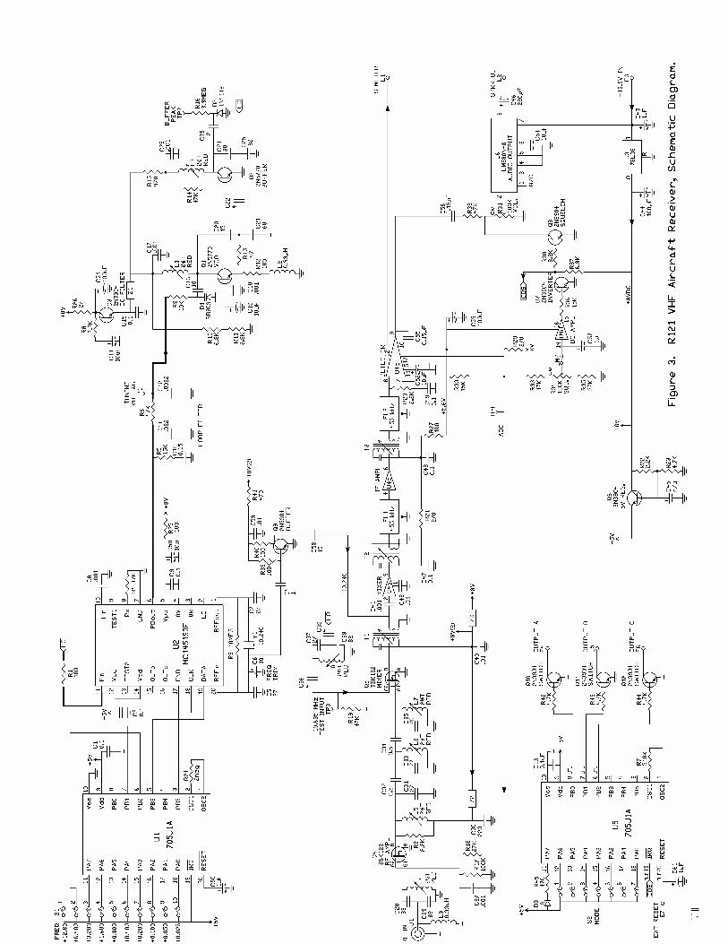
THEORY OF OPERATION. The R121 is a frequency synthe-
sized vhf am receiver. Refer to the schematic diagram for the following discussion.
Low noise dual-gate mos fet’s are used for the RF amplifier and mixer stages. The output of first mixer Q5 Is coupled through 10.695 MHz trans-former T1 to the second mixer.
U4 provides IF amplification, a 2nd mixer to convert to 455 kHz, a detec-tor, if agc, rf agc and squelch. Ce-ramic filters FL1 and FL2 provides adjacent channel selectivity at 455 kHz. T2 and T3 provide impedance matching for the filters. U4c is an en-velope detector. It also provides agc for the if stages within U4 and delayed rf agc for gate2 of Q4. TP4 allows monitoring of the agc voltage as an indication of signal strength to use for alignment. U4c pin 12 provides a current source to drive an external S-meter based on the agc signal level.
Detected audio is applied through volume control R31 to audio amplifier U6. Squelch transistor Q8 mutes this audio when no signal is present. Q8
is driven through squelch amplifiers U4d and Q7. Squelch control R34 sets the threshold at which the squelch opens. C57 provides a slight delay to eliminate switching clicks when the audio is turned on and off.
The injection frequency for the first mixer is generated by vco (voltage con-trolled oscillator) Q1. The injection frequency is 10.695 MHz above the receive channel frequency. The out-put of the vco is buffered by Q2 to minimize effects of loading and voltage variations of following stages from modulating the carrier frequency. The buffer output is applied through a double tuned circuit to gate 2 of mixer Q5.
The frequency of the vco stage is controlled by phase locked loop syn-thesizer U2. A sample of the vco out-put is applied through the buffer stage and R1 to a prescaler in U2. The pre-scaler and other dividers in the syn-thesizer divide the sample down to 5kHz.
A reference frequency of 10.240 MHz is generated by a crystal oscilla-tor. The reference is divided down to 5 kHz.
The two 5kHz signals are com-pared to determine what error exists between them. The result is a slowly varying dc tuning voltage used to phase lock the vco precisely onto the desired channel frequency.
The tuning voltage is applied to carrier tune varactor diode D1, which varies its capacitance to tune the tank circuit formed by L1/C20/C21. C16 limits the tuning range of D1. The tuning voltage is applied to D1 through a third order low pass loop filter, which removes the 5kHz refer-ence frequency from the tuning volt-age to avoid whine.
Serial data to indicate the desired channel frequency and other opera-tional characteristics of the synthe-sizer are applied to synthesizer U2 by microcontroller U1. Everything the synthesizer ic needs to know about the band, division schemes, reference frequency, and oscillator options is generated by the controller. Informa-tion about the base frequency of the band the receiver is to operate on and the channel within that band is calcu-lated in the controller based on infor-mation programmed in the eprom on the controller and on channel settings done on dip switch S1. Whenever the microcontroller boots at power up, the microcontroller sends several bytes of serial data to the synthesizer, using the data, clock, and /enable lines running between the two ic’s.
Some of the 10.240MHz signal
generated in U2 is used for the injec-tion to second mixer U4a. Q9 pro-vides buffering for this injection signal.
Microcontroller U5 provides the in-telligence to control runway lights and detect downed aircraft ELT signals. It senses squelch openings at interrupt pin 19, and its three outputs drive switching transistors Q10, Q11, and Q12. These transistors are capable of driving external relays and may be used in other ways as described in the Installation section. Care must be used to avoid reverse polarity, over-voltage, and transients, all which can damage the transistors.
+13.6Vdc power for the receiver is applied at E3. Audio output amplifier U6 is powered directly by the +13.6Vdc. All the other stages are powered through voltage regulators for stability and to eliminate noise. U3 is an 8Vdc regulator to power if amplifier U4, RF amplifier Q4, mixer Q5, and the vco, buffer, and phase de-tector in the synthesizer. Additional filtering for the vco and buffer stages is provided by capacitance amplifier Q3, which uses the characteristics of an emitter follower to provide a very stiff supply, eliminating any possible noise on the power supply line. Q6 provides a stiff +5Vdc supply for the frequency synthesizer and microcon-trollers, which are low current CMOS devices.
TROUBLESHOOTING.
General. The usual troubleshooting tech-
niques of checking dc voltages and signal tracing with an RF voltmeter probe and oscilloscope will work well in troubleshooting the R121. DC volt-age charts and a list of typical audio levels are given to act as a guide to troubleshooting. Although voltages may vary widely from set to set and under various operating and measure-ment conditions, the indications may be helpful when used in a logical troubleshooting procedure.
Current Drain. Power line current drain normally
is about 75 mA with volume turned down or squelched and up to 200 mA with full audio output.
If the current drain is approxi-mately 100 mA with no audio output, check to see if voltage regulator U3 is hot. If so, and the voltage on the 8V line is low, there is a short circuit on the +8Vdc line somewhere. U3 limits the short circuit current to 100mA to protect the receiver from damage. If
©2000 Hamtronics, Inc.; Hilton NY; USA. All rights reserved. Hamtronics is a registered trademark. Revised: 12/3/04 - Page 8 -
you clear the short circuit, the voltage should rise again. U3 should not be damaged by short circuits on its out-put line; however, it may be damaged by reverse voltage or high transient voltages.
A good way to isolate short circuits and other overloads on the 8V or 5V lines is to disconnect components in series with the path, for instance, fer-rite beads or Q6. With so many things connected to the B+ lines, it is difficult to find the problem without eliminating large portions of the load that way.
Audio Output Stage. Note that audio output ic U6 is de-
signed to be heatsunk to the pc board through the many ground pins on the ic. When running moderately low au-dio levels as most applications re-quire, it is no problem to use an ic socket; so we have provided one for your convenience. If you will be run-ning high audio levels, check to see if the ic is getting hot. If so, you should remove the ic socket, and solder the LM-380N-8 ic directly to the board for better heatsinking.
If audio is present at the volume control but not at the speaker, the audio ic may have been damaged by reverse polarity or a transient on the B+ line. This is fairly common with lightning damage.
If no audio is present on the vol-ume control, the squelch circuit may not be operating properly. Check the dc voltages on U4d, Q7, and Q8.
RF Signal Tracing. If the receiver is completely dead,
try a 10.695 MHz signal applied to TP-3 (the top lead of R19), using coax clip lead. Connect coax shield to pcb ground. Set level just high enough to get a change of agc voltage at TP4. At 10µV, you should notice some degree of change in agc voltage.
Also, check the 10.240 MHz oscil-lator with a scope or by listening with an hf receiver or service monitor.
A signal generator on the channel frequency can be injected at various points in the front end. If the mixer is more sensitive than the RF amplifier, the RF stage is suspect. Check the dc voltages looking for a damaged fet, which can occur due to transients or reverse polarity on the dc power line. Also, it is possible to have the input gate (gate 1) of the RF amplifier fet damaged by high static charges or high levels of RF on the antenna line, with no apparent change in dc volt-ages, since the input gate is normally at dc ground.
Synthesizer Circuits. Following is a checklist of things to
look for if the synthesizer is suspected of not performing properly.
a. Check the output frequency of the vco buffer with a frequency coun-ter. It should be 10.695 MHz above the channel frequency.
b. Check tuning voltage at TP1. It should be about +4Vdc. Actual range over which the unit will operate is about +1Vdc to just under +8Vdc. However, for optimum results, the vco should be tuned to allow operation at about +4Vdc center voltage.
c. Check the operating voltage and bias on the vco and buffer.
d. Check the 10.240 MHz oscilla-tor at pin 1 of the synthesizer ic (ac-tually best to check at lead of R3; avoid trying to probe surface mount ic leads which are close together). A scope should show strong signal (sev-eral volts p-p) at 10.240 MHz.
e. Check the oscillator at pin 1 of microcontroller ic U1 with a scope. There should be a strong ac signal (several volts p-p) at the oscillator fre-quency.
f. The data, clock, and /enable lines between the microcontroller and synthesizer ic’s should show very brief and very fast activity, sending data to the synthesizer ic shortly after the power is first applied or a dip switch setting is changed. Because this hap-pens very fast, it can be difficult to see on a scope. Use 100µSec/div, 5Vdc/div, and NORMAL trigger.
g. Check the microcontroller to see that its /reset line is held low momentarily when the power is first applied. C1 works in conjunction with an internal resistor and diode in the ic to make C1 charge relatively slowly when the power is applied. It should take about a second to charge up.
h. Check the switch settings to be sure you have the correct frequency information going to the microcontrol-ler. Check each of the output lines of the switch to verify that the voltage actually is present.
i. If you have a scope or spec-trum analyzer, you can check the output pin of the divide by 64 presca-ler at pin 13 of U2. There should be a strong signal (several volts p-p) at about 2 MHz. If this signal is absent, there may not be sufficient level of sample signal from the buffer at U2 pin 11. Be careful not to short adja-cent pins of the ic.
Microphonics, Hum, and Noise. The vco and loop filter are very
sensitive to hum and noise pickup
from magnetic and electrical sources. Some designs use a shielded com-partment for vco’s. We assume the whole board will be installed in a shielded enclosure; so we elected to keep the size small by not using a separate shield on the vco. However, this means that you must use care to keep wiring away from the vco circuit at the right side of the board. Having the board in a metal enclosure will shield these sensitive circuits from flo-rescent lights and other strong sources of noise.
Because the frequency of a synthe-sizer basically results from a free run-ning L-C oscillator, the tank circuit, especially L1, is very sensitive to mi-crophonics from mechanical noise coupled to the coil. You should mini-mize any sources of vibration which might be coupled to the receiver, such as motors. In addition, it helps greatly to prevent the molded coil from vibrating with respect to the shield can. Both the coil and can are sol-dered to the board at the bottom, but the top of the coil can move relative to the can and therefore cause slight changes in inductance which show up as frequency modulation. Securing the top of the plastic coil form to the shield can with some type of cement or nail polish greatly reduces the mi-crophonic effects. This practice is recommended in any installation where vibration is a problem, and the factory normally cements this coil for that reason.
Excessive noise on the dc power supply which operates the receiver can cause noise to modulate the syn-thesizer output. Various regulators and filters in the receiver are designed to minimize sensitivity to wiring noise. However, in extreme cases, such as in mobile installations with alternator whine, you may need to add extra fil-tering in the power line to prevent the noise from reaching the receiver.
Other usual practices for mobile installations are recommended, such as connecting the + power and ground return lines directly to the battery in-stead of using cigarette lighter sockets or dash board wiring.
To varying degrees, whine from the 5kHz reference frequency may be heard on the signal under various cir-cumstances. If the tuning voltage re-quired to tune the vco on frequency is very high or low, near one extreme, the whine may be heard. This can also happen even when the tuning voltage is properly near the 4Vdc cen-ter if there is dc loading on the loop filter. Any current loading, no matter how small, on the loop filter causes

©2000 Hamtronics, Inc.; Hilton NY; USA. All rights reserved. Hamtronics is a registered trademark. Revised: 12/3/04 - Page 9 -
the charge pump in the phase detec-tor to pump harder to maintain the tuning voltage. The result is whine on the signal. Such loading can be caused by connecting a voltmeter to TP1 for testing, and it can also be caused by moisture on the loop filter components.
Phase noise is a type of white noise which phase locked loop synthesizers produce. Many efforts are made dur-ing the design of the equipment to re-duce it as much as possible. The phase noise in this unit should be al-most as good as a crystal oscillator radio. If you notice excessive white noise even though the signal is strong, it may be caused by a noisy vco tran-sistor, Q1. Try swapping with the buffer transistor, Q2, which is the same type and see if that helps. When using a replacement transistor for repairs, be sure to use one of good quality.
If you suspect noise is being intro-duced in the synthesizer, as opposed to the signal path from the antenna to the detector, you can listen to the in-jection signal at 10.695 MHz above the channel frequency on a receiver or service monitor and hear what just the injection signal sounds like. Put a pickup lead on top of the receiver board so you have a strong sample to hear so you are sure the noise is not due to weak signal pickup at the test receiver.
Typical Dc Voltages. Tables 4-6 give dc levels measured
with a sensitive dc voltmeter on a sample unit with 13.6 Vdc B+ applied. All voltages may vary considerably without necessarily indicating trouble. The charts should be used with a logi-cal troubleshooting plan. All voltages are positive with respect to ground except as indicated.
Use caution when measuring volt-ages on the surface mount ic. The pins are close together, and it is easy to short pins together and damage the ic. We recommend trying to connect meter to a nearby component con-nected to the pin under question. Also, some pins are not used in this design, and you can generally not be concerned with making measure-ments on them.
Note: On the schematic diagram, these symbols indicate logic levels:
indicates active lo (0V in stated condition) indicates active hi (5V in stated
condition)
Typical Audio Levels. Table 7 gives rough measurements
of audio levels. Measurements were taken using an oscilloscope, with no input signal, just white noise (squelch open) so conditions can be reproduced easily.
REPAIRS. If you need to unsolder and replace
any components, be careful not to damage the plated through holes on the pc board. Do not drill out any holes. If you need to remove solder, use a solder sucker or solder wick. A toothpick or dental probe can be used with care to open up a hole.
If you need to replace surface mount ic U2, first be very sure it is damaged. Then, carefully cut each lead off the case with fine nose cut-ters. Once the case is removed, indi-vidual leads can be unsoldered and the board can be cleaned up. Care-fully position the new ic, and tack sol-der the two opposite corner leads before any other leads are soldered. This allows you to melt the solder and reposition the ic if necessary. Once you are sure, the remaining leads can be soldered. If you get a solder short between leads, use a solder sucker or solder wick to remove the excess sol-der.
Table 4. Typical Test Point Voltages
TP1 Tuning V. Normally set at 4V
TP2 Buffer approx. 0.8V TP3 Test Input (No reading) TP4 AGC Varies from about 4.5V
with no signal to 0.2V with strong signal (~3000µV)
Table 5. Typical Xstr DC Voltages
Xstr Stage E(S) B(G1) C(D) G2
Q1 vco 1.5 2.0 7.0 - Q2 buffer 0 0.75 4.5 - Q3 dc filter 6.8 7.4 7.6 - Q4 RF ampl 0 0 8 3.5 Q5 Mixer 0 0 8 0 Q6 5V regul. 5 5.6 8 - Q7 sq open 0 0.67 0.15 - sq closed 0 0.03 5 - Q8 sq open 0 0.14 0 - sq closed 0 0.66 0.01 - Q9 Buffer 0 0.7 3.3 - Q10-Q12 on 0 0.7 * - off 0 0 * - * depends on circuit being switched
Table 6. Typical IC DC Voltages
U1-1 2.3 U1-20 5 U1-2 2.3 U2-1 2.2 U2-10 2.6 U2-2 5V locked, U2-11 2.6 2.5V unlocked U2-12 5 U2-3 8 * U2-13 3 .2* U2-4 8 * U2-14 5 U2-5 8 U2-15 * U2-6 0-8 (4V tuned) U2-16 * U2-7 0 U2-17 5 U2-8 4.5 U2-18 0 U2-9 5 * U2-19 5 * = pin not used U2-20 2 U4-1: 0.86 U4-11: 0.64 U4-2: 1.4 U4-12: 0.2 (no U4-3: 5.4 meter connected) U4-4: 0.68 U4-13: 4.5 U4-5: 0 U4-14: U4-6: 5.5 sq open 0.72 U4-7: 1.4 sq closed 0.85 U4-8: 1.4 U4-15: U4-9: 0.77 fully open 3.2 U4-10: 5.6 fully closed 0 U5-1 2.3 U5-20 5 U5-2 2.3 U6-1: 0 U6-5: 0 U6-2: 0 U6-6: 6 U6-3: 0 U6-7: 13.6 U6-4: 0 U6-8: 6.8
Table 7. Typical Audio Voltages Audio Test Point Normal Level U4-9 Detector 100mV p-p Top of Volume Con-trol R31
75mV p-p
Speaker Out E2 with volume up full
up to 4V p-p

©2000 Hamtronics, Inc.; Hilton NY; USA. All rights reserved. Hamtronics is a registered trademark. Revised: 12/3/04 - Page 10 -
PARTS LIST. Following are notes specific to cer-
tain parts. Microcontrollers must be factory
programmed for each application, and they are not interchangeable.
Resistors used as test point or external connection point. These must be installed on the board ori-ented properly and with the top loop an extra 1/6” high to allow for connec-tions to the loop later. (See detail in component location diagram.)
This part is surface mounted on rear of board.
Caution: Ic’s and fet's are static sensitive. Use appropriate handling precautions to avoid damage.
Ref Desig Description (marking) C1-C2 0.1µf C3 n/a C4 1pf C5 27pf C6 11pf var cap (blue) C7 27pf C8 .001µf C9 0.1µf C10 0.15µf mylar (red) C11 .01µf C12 .001µf C13 0.1µf C14 10µf electrolytic C15 0.1µf C16 10pf C17-C18 .001µf C19 10µf electrolytic C20 15pf C21 68pf (1206 size) C22 4pf C23 .001µf C24 30pf C25 82pf C26 2pf C27 .001µf C28 33pf C29 82pf C30 220pf C31 27pf C32 0.5pf C33 27 pf C34 0.5pf C35 22pf C36 4pf C37 27pf C38 82pf C39 4pf C40 .01µf
C41 .001µf C42 .01µf C43 1µf electrolytic C44 100µf electrolytic C45 not used C46 220µf electrolytic C47-C49 0.1µf C50 10µf electrolytic C51 100µf electrolytic C52 10µf electrolytic C53 100µf electrolytic C54 10µf electrolytic C55 .01µf C56 0.15µf mylar (red) C57 1µf electrolytic C58 47pf C59 .01µf C60-C61 1µf electrolytic D1 BB809 varactor diode D2 1N4148 switching diode D3 mini red LED FL1-FL2 455kHz ceramic filter, type "E" J1 RCA jack L1 2½ turn slug-tuned coil (red) L2 0.33µH RF choke (red-sil-orn-orn) L3-L8 2½ turn slug-tuned coil (red) L9 0.33µH RF choke (red-sil-orn-orn) Q1-Q2 2N5770 Q3 2N3904 Q4-Q5 3SK122 MOS FET Q6 2N3904 Q7-Q9 2N5770 Q10-Q12 2N3904 R1 100Ω R2 2.2K R3 10meg R4 47K R5 15K R6 100K R7 510K R8 2.2K R9 10K R10 6.8K R11 3.9K R12 180Ω R13 47Ω R14 47K R15 470Ω R16 3.9meg R17 100K R18 27K R19 47K R20 2.2K
R21 270Ω R22 2.2K R23 4.7K R24 2meg R25 100Ω R26 27Ω R27 100Ω R28 n/a R29 270Ω R30 15K R31 100K VOLUME R32-R33 47K R34 100K SQUELCH R35 27K R36 15K R37 6.8K R38 8.2K R39 100K R40 100Ω R41 470Ω R42-R44 4.7K R45 470Ω S1 10 pos. dip switch S2 7 pos. dip switch T1 10.7MHz IF xfmr (7A-691F) T2-T3 455kHz IF xfmr (T1003 or RLC-352) U1 MC68HC705J1A µP U2 MC145190F synthesizer U3 78L08 regulator U4 CA3088 i-f ampl detector U5 MC68HC705J1A µP U6 LM380N-8 af output Y1 10.240 MHz crystal Z1-Z3 Ferrite bead, prestrung
Figure 4. Placement of U2 Under PC Board. Note that dot on ic goes toward rear of the board.

©2000 Hamtronics, Inc.; Hilton NY; USA. All rights reserved. Hamtronics is a registered trademark. Revised: 12/3/04 - Page 11 -
Detail of LED Installation
PC Board
1/32"
3/16"
©2000 Hamtronics, Inc.; Hilton NY; USA. All rights reserved. Hamtronics is a registered trademark. Revised: 12/3/04 - Page 12 -