r fighter 1310 - nibe · fighter 1310 is a heat pump for heating large properties such as apartment...
TRANSCRIPT

RINSTALLATION AND MAINTENANCE INSTRUCTIONS
FIGHTER 1310MOS GB 0349-1 611854FIGHTER 1310
LEK


FIGHTER 1310
General information for the installation engineerTransport and storage ................................................ 14Erecting the heat pump .............................................. 14Floating condensation ................................................ 14Fixed condensation .................................................... 14Collectors .................................................................... 14Inspection of the installation ...................................... 14
Control (also with accessories)General ...................................................................... 15Settings ...................................................................... 15Drying the concrete base .......................................... 19
Pipe connectionsGeneral ...................................................................... 20Pipe connection (heating water) ................................ 20Pipe connection (brine) .............................................. 20Free cooling ................................................................ 20Pressure expansion vessel ........................................ 21Pump capacity diagrams, heating water side ............ 21Brine capacity diagram, collector side ...................... 21
DockingGeneral ...................................................................... 22Option 1 FIGHTER 1310 docked withoil-fired boiler and water heater .................................. 22Option 2 FIGHTER 1310 docked withelectric boiler and water heater .................................. 23Option 3 Two or more FIGHTER 1310s docked with boiler and water heater .......................... 24Option 4 Control, double curves ................................ 25
Electrical connectionsElectrical installation .................................................. 26Connecting the supply ................................................ 26External control of the electrical supplement andcompressor ................................................................ 27Connecting the outside sensor .................................. 27Connecting temperature sensors supplied with the unit ................................................................ 28Connecting more than one FIGHTER 1310 .............. 28Temperature drop ...................................................... 28Terminal blocks for external units .............................. 29Reversing valve .......................................................... 29Extra hot water .......................................................... 29Common alarm .......................................................... 29Standby mode ............................................................ 29
Control with oil supplement option 1Connection ................................................................ 30Menu 19 ...................................................................... 31Control of additional heat, oil ...................................... 31
Control with electrical supplement up to seven steps option 2
Connection ................................................................ 32
Menu 19 ...................................................................... 33Controlling the additional heat, electrical .................. 33
Control with two or more F 1310s option 3Connection ................................................................ 34Menu 19 ...................................................................... 35Function ........................................................................35
Control, double curves option 4Connection ................................................................ 36Menu 19 ...................................................................... 37Control, double curves with external mixing valve ......37Temperature sensor placement ..................................37Connection, external mixing valve ..............................37Connection, external additional heat............................37Temperature set back ..................................................37
Commissioning and adjustingFilling and venting the brine system .......................... 38Filling the heating/heating water systems .................. 38Starting and checking ................................................ 38Internal venting valves ................................................ 39Readjustment, heating water system ........................ 39Readjustments, brine system .................................... 39Internal control panel .................................................. 39
Setting the automatic heating control systemSetting with diagrams ................................................ 40Heating curve offset -2 .............................................. 40Heating curve offset 0 ................................................ 40Heating curve offset +2 .............................................. 40
Circuit diagramCircuit diagram .......................................................... 41
Component positionsComponent positions .................................................. 42
List of componentsList of components .................................................... 43
DimensionsDimensions and setting-out coordinates .................... 44
AccessoriesAccessories ................................................................ 45
Technical specificationsTechnical specifications ............................................ 46Enclosed kit ................................................................ 46
Dealing with malfunctionsLow room temperature .............................................. 47High room temperature .............................................. 47Low hot water temperature or no hot water .............. 47Indications .................................................................. 47Draining, heat water system ...................................... 48Draining, brine system ................................................ 48Helping the circulation pump to start .......................... 48Cleaning the circulation pump .................................... 48
GeneralConcise product description .................................... 2Setting table .............................................................. 2
System descriptionPrinciple of operation ................................................ 3
Front panelFront panel ................................................................ 4Functions .................................................................. 5Setting different operating modes (even with accessories) ............................................ 5
ControlGeneral .................................................................... 6
Setting heat .............................................................. 6Changing the room temperature .............................. 6Basic values for the automatic heating control system .......................................................... 6Basic values .............................................................. 7Heat production ........................................................ 7Domestic hot water .................................................. 7Brine pump ................................................................ 7Fixed condensing ...................................................... 7
Control, normalInformation available on the display .......................... 8
Control, double curvesInformation available on the display ...................... 11
Contents 1
For the Installer
For Home Owners

General
FIGHTER 1310
For Home Owners
2
In order to get the ultimate benefit from your heat pump FIGHTER 1310 you should read throughthe For Home Owners section in this Installation and Maintenance Instruction.
FIGHTER 1310 is a heat pump for heating large properties such as apartment buildings and industri-al properties. The ground, rock or lakes can be used as the heat source.
FIGHTER 1310 is a Swedish made quality product offering a long life span and safe operation.
Installation date
Accessories:Hot water control ............ ■■Temperature signal distributor
■■Room control .................. ■■Other .............................. ■■
Type designation / serial number
FIGHTER 1310- _ _ kW / 689 _ _ _ _ _ _ _ _ _ _ _
Installation engineers
Completedby the installer when the heat pump is installed
The type of brine mixing proportion/freezing point
Active drilling depth/collector length
Commissioning checksBrine temperature (supply/return) _____ / _____
(Nominal temperature diff 2 - 5 °C)Heating water flow (in/out) _____ / _____
(Nominal temperature diff 5 - 10 °C)
* The immersion heater, hot water
Date ___________ Signature
BasicMenu settings
2b Temp Sink ............ 83 WW-in ............ 463 HW start ............ 444 Brine ............ -125 Curveslope ............ 9
5/17 Parallel ............5b Room comp ............ 45c WW-Out min ............ 155c WW-out max ............ 459b HP-min ............ 609D Add-min ............30010 WW diff HP ............ 13
Control, double curves
5 Curveslope 1 ............ 95 Curveslope 2 ............ 95b Parallel 1 ............ 25b Parallel 2 ............ 65c Room comp ............ 45d WW-Out min ............ 155d WW-out max ............ 555e WW-out 2 min ............ 155e WW-out 2 max ............ 55
BasicMenu settings
10 Diff HP-Add ............ 311 HP-int ............ 2011 HWT-stop ............ 50*12 XWW-stop ............ 6512 XWW-int ............ 1412b Shunt P ............ 3012b Shunttime ............ 1014 Add ............ 118 HP-no ............ 018 HW-val ............ 119 Shunt ............ 0
Setting HP A ..................Setting HP B
Settings

FIGHTER 1310 consists of two heat pump modulesand a control computer with a display to control theheat pump and any additional heat. FIGHTER 1310has built-in circulation pumps, making it easy to con-nect to the heating water and brine circuits.
The absorption of heat from the heat source (rock,ground or lake) is through a closed brine system con-taining water mixed with antifreeze.
Ground water can also be used as a heat source. Thisrequires an intermediate heat exchanger.
The brine emits its heat to the refrigerant in the heatpump’s evaporator. The refrigerant then vaporises andis compressed in the compressor. The refrigerant, withits increased temperature, is led into the condenserwhere it emits its energy to the heat water circuit.
System description 3For Home Owners
FIGHTER 1310
Principle of operation
CMP
Ev Exv Con
Com
HW return
HW flow / HM flow
HM-r
HM flow
CM-r
CM-f
B
A
Cirk.pump
Värmepump
Varmvatten
Tillsatsvärme
Larm
Kontrollera
att vatten
finns i pan-
nan innan
den in-
kopplas.
1
R
0
HMP-A
HMP-B
SF
SF
SF

+20
-2
1
R
0
VB-Fram 49 (50) °CVarmvatten 51 °C
Front panel
FIGHTER 1310
For Home Owners
4
Indicator lampsFunction keys
Display
Front panel
B
Switch
A
D
Increase/reduceheat
C
E
NOTE! Make sure there is water in the heat pump before
turning the switch (A) into position 1 or R.
WW-out 49(50)°CHot-Water 51°C

SwitchThree position switch (1 0 R).0 Heat pump off.1 Normal mode.
All control functions connected.R Standby. Not connected at the factory
Function keysChannelWindow menu selection.
IncreaseIncreases the current value.
ReduceReduces the current value.
Operating modeAdditional heat (accessory) and/or roomheat on/off. See the following section.
Extra hot waterTemporary or periodic raising of thewater temperature is allowed (accesso-ry).
DisplayIn normal mode the display shows:WW-out: Actual heating water temperature, thetemperature of the water leaving the heat pump.The figure in brackets shows the calculated flowtemperature.Hot water: Actual hot water temperature(accessory).
Indicator lampsRoom heating – A steady light indicates that room
heating is allowed.
Heat pump– A flashing light shows that a compres-
sor is running.– A steady light shows that both com-
pressors are running.
Hot water (accessory)– A steady light shows that hot water
charging is in progress.– Rapid flashing shows that temporary
raising of the hot water temperaturehas been selected (approx 60 °C for24 hours)*.
– Slow flashing shows that periodic rais-ing of the hot water temperature hasbeen selected (approx 60 °C for thechosen period)*.
Additional heat (external)– A steady light means that the addition-
al heating is on.– Slow flashing means that additional
heating is allowed.– Rapid flashing means that only addi-
tional heating is on.
AlarmFlashes rapidly when a fault hasoccurred.
Raise/lower heatThis knob is used to raise or lower the roomtemperature (i.e. it changes the temperature ofthe WW-out). Applies to docking options 1 and3.
Front panel 5For Home Owners
B
C
E
Functions
Normal mode (basic setting):Supplement ready to start if needed. Hot watercharging cuts in if necessary.
LEDs:Room heating: LitHot water: Lit during hot water chargingAdditional heat Flashing / Steady lightNo additional heat mode:Press the Operating mode button once.Room heating: LitHot water: Lit during hot water chargingAdditional heat Not litPosition No room heating:Press the Operating mode button again.Room heating: Not litHot water: Lit during hot water chargingAdditional heat Not lit
The system returns to normal mode the next time theOperating mode button is pressed.
Normal mode: No raised hot water temperatureconnected.
Temporarily raised hot water temperature: Press the Extra hot water button once. A raised hotwater temperature is obtained for 24 hours. The Hotwater LED flashes rapidly. Lit during charging.
Periodically raised hot water temperature:Press the Extra hot water button again. The hot watertemperature is raised as shown on menu 12. The Hotwater LED flashes slowly. Lit during hot water charging.The next time Extra hot water is pressed you return tonormal mode.
* Only possible with an external immersion heater.
Setting different operating modes (also applies with accessories)
FIGHTER 1310
A D

ControlsFor Home Owners
6
FIGHTER 1310
Setting takes place by programming the curve slope,see the section ”Available information and settings onthe display”, and by setting the Heating curve offsetusing the Increase/reduce heat knob on the panel.Initial values can be taken from the map if you do notknow which values to set, see the Control Basic val-ues section.If the required room temperature is not obtained, read-justment may be necessary.
NOTE! Wait one day between settings so that thetemperatures have time to stabilise.
Readjusting the settingCold weather conditions
If the room temperature is too low, increase thevalue for the heating curve by one step.If the room temperature is too high, reduce thevalue for the heating curve by one step.
Warm weather conditionsIf the room temperature is too low, turn theIncrease/reduce heat knob one step clockwise.If the room temperature is too high, turn theIncrease/reduce heat knob one step anticlockwise.
The indoor temperature depends on several factors.Sunlight and heat emissions from people and house-hold machines are normally sufficient to keep thehouse warm during the warmer parts of the year.When it gets colder outside, the heating system mustbe started. The colder it gets, the hotter the radiatorsor the underfloor heating pipes must be. With theFIGHTER 1310, this adjustment is done automaticallyby a control computer. Before the computer can dothis, some basic settings are required. FIGHTER 1310also offers the possibility to control two different tem-perature curves.
The heat pump is controlled by built-in sensors forflow and return brine temperatures (collector). Brinereturn temperatures can, if so required, be limited to aminimum (e.g. for ground water systems).
Heat production is usually controlled using the floatingcondensing principle. This means that the tempera-ture level needed for heating at a given outside tem-perature is produced on the basis of values taken fromsensors for outside temperature and flow temperature.Room sensors can also be used as an option to com-pensate for variations in room temperature.
General
Changing the room temperature manuallyIf you want to temporarily or permanently increase orlower the indoor temperature in relation to the previ-ous heat setting turn the Increase/reduce heat knobclockwise or anticlockwise. One line approximatelyrepresents a 1 degree change in room temperature. NOTE! An increase in the room temperature may beinhibited by the radiator or floor heating thermostats, ifso these must be turned up.
Changing the room temperature
Setting heat

Controls 7For Home Owners
The brine pump is in operation when one of the com-pressors is in operation and when the selector switchfor brine pump (40) is in the Auto position.
FIGHTER 1310 can be docked with an external unitwith its own automatic heating control system. FIGHT-ER 1310 then delivers heat up to a fixed temperaturelevel. This is known as fixed condensation. To regu-late the room temperature, see the instructions for theexternal units.
When fitted with the Hot water control accessory and,for instance, our hot water accumulator VPA, theFIGHTER 1310 can be used for hot water production.In those cases connection to the water heater hasbeen made via the accessory Hot water control andexternal immersion heaters, are installed in the waterheater the function Extra hot water can be utilised.This function increases the hot water temperaturefrom the normal 50 °C up to approx. 60 °C with thehelp of the immersion heater.
The supply of heat to the building is controlled by thecontrol computer settings (curve slope and offset).After adjustment the correct amount of heat for thecurrent outdoor temperature is supplied. The heatpump flow temperature (WW-out) will hover aroundthe theoretical required value (the value in brackets onthe display). For subnormal temperatures the comput-er calculates a deficit in the form of degree minutes,which results in the acceleration of heat production.The larger the subnormal temperature, the greater theheat production.
Control, normalThe heat pump’s control computer can control anexternal electric boiler/cassette in up to seven powersteps, or an external oil-fired boiler and mixingvalve.
Control, double curvesCurve 1 controls the operation of the compressors.Curve 2 controls an external mixing at lower tempera-tures. In this operating instance the supplement is limitto one step.
Heating Hot water
Brine pump
Fixed condensation
FIGHTER 1310

Control, normal
FIGHTER 1310
For Home Owners
8
OutdoorCurrent outdoor temperature.
Boiler ***Current boiler water temperature.(Start temperature for shunting-in from boiler.)Displayed alternately with menu 2c.
OutdoorCurrent outdoor temperature.
Temp Sink ****Temperature drop, the heating curve is lowered,for example, by 8 degrees when the contact inthe room unit (accessories) makes. If the roomunit (RT20) is connected a room sensor (RG20)cannot be connected.In normal mode, the above information appears on the
LCD-display of the heat pump.WW-Out
Current flow temperature(Calculated flow temperature.)
Hot-water *Current hot water temperature.
1
2b
OutdoorActual outside temperature.
Room **Actual room temperature.[P] (The set Set point value on the room sensor (RG20).)Setting range: 5 - 30 °C.
2c
2
* Only displayed if the accessory VST 11 is connected.** Only displayed if a room sensor is connected.*** Only displayed if a boiler sensor is connected.**** Only displayed if the button Increase is pressed in, the set value can then be changed.
The function only works if the accessory RT 20 is connected.
FIGHTER 1310 has a two-line LCD display. The heatpump can be set via this display and its associatedbuttons.
Channel selectionThe Channel button lets you browse throughthe following display modes to find the informa-
tion you require. Values within brackets are also described withinbrackets.If a value is programmable, this is denoted by a [P](Programmable) in front of the value.If the next value cannot be changed, you can accessthe next menu by pressing Channel.
SettingThe first step when changing a value is to pressthe Increase button once. A cursor (line) thenappears under the value. The value can then beincreased or reduced using the Increase orReduce buttons.
Available information and on-display settings
Outdoor -14 °CBoiler 25 °C
Outdoor -14 °CTemp Sink 8 °C
Outdoor -14 °CRoom 20,5(20) °C
WW-out 47(52) °CHot-water 48 °C

Control, normal 9For Home Owners
FIGHTER 1310
Brine InTemperature of the incoming brine.
Brine OutTemperature of the outgoing brine.[P] (Minimum permitted temperature for the brine
return from the heat pump). This setting should only be changed by a special-ist. It is used for minimum limiting with alarm, forexample as an anti-freezing function in ground-water systems or exhaust air systems.A suitable setting with an intermediate heatexchanger would be 0 °C. When the lowest value(-12) is set, minimum limiting and the alarm aredisabled.Setting range: -12 - +10 °C.
WW-inActual temperature of incoming heating water.[P] (Max permitted return temperature for com-pressor operation.)Setting range: 40 - 60 °C.
HW startThe current temperature at the bottom part of thewater heater’s outer shell. [P] (Chosen start level for hot water production.)Setting range: 5 - 60 °C.
3
WW stopActual temperature in lower part of water heaterouter jacket. [P] (Chosen stop level for hot water production.)Setting range: 15 - 70 °C or A.
3b
4
Available information and on-display settings
Curveslope[P] Set heating curve.
Room-comp **[P] When the room temperature deviates by1 °C, the WW-out set point is changed by thevalue indicated.A higher value gives a quicker reaction if thetemperature in the premises is too high or toolow. The normal value for a radiator system is 4. Setting range: 0 - 6 °C
5b**
5*
* Displayed only if more than one heat pump isinstalled (i.e. if the chosen value for HP-no. inmenu 18 is greater than > 0).
** Only displayed if a room sensor is connected.
Curveslope[P] Set heating curve.Setting range: 1 – 15
Parallel *[P] When the chosen HP-no. setting (menu 18) is>0, parallel offset is set by programming in thismenu instead of setting with the knob.Setting range: -10 – +10
Curveslope 9Parallel 0
Curveslope 9Room comp 4 °C
WW-in 37(46) °CHW start 49(44) °C
WW-in 37(46) °CWW-stop 49(A) °C
Brine In +3 °CBrine 0 0(-12) °C

Control, normal
FIGHTER 1310
For Home Owners
10
Available information and on-display settings
NOTE! Enter the chosen settings in the tableon page 2 of this manual. The details
are important for service work.
HP start AShows the total number of starts of heat pumpmodule A.
HP start BShows the total number of starts of heat pumpmodule B.
HP-time AShows the total number running hours for heatpump module A.
HP-time BShows the total number of running hours for heatpump module B.
English[P] Chosen language setting. Press Increase tochange language. When you have chosen therequired language, press the Channel button.Channel 1 re-appears.
A HP onSuccessively shows the following operating sta-tuses: HP off, HP on, HP start in X minutes orHigh return temp for module A or B respectively.
6
7
8
5c
This menu is a submenu to menu 5 (or 5b). It isactivated by placing the cursor under the valuefor Curve slope (or Room-comp if a room sensoris connected) and pressing the Channel button.
WW-out min[P] Setting for the minimum calculated flow linetemperature. Setting range: 10 - 50 °C.Preset value: 15 °C
WW-out max[P] Setting for the maximum calculated flow linetemperature. Setting range: 30 - 70 °C.Preset value is 55 °C.The heating water flow temperature may tem-porarily go above or below the setting as a resultof normal fluctuations.For example, for underfloor heating with floatingcondensation, suitable settings might be min 20 °C, max 40 °C.With fixed condensation, the same setting is cho-sen for the minimum and maximum levels. (Sen-sor location, temperature setting and pump floware taken into account.)
WW-out min 15 °CWW-out max 55 °C
HP start A 10HP start B 4
English 0A HP on
HP-time A 40 hHP-time B 10 h

Control, double curves 11For Home Owners
FIGHTER 1310
Available information and on-display settings
NOTE! If Control, double curves, is selected
the value in menu 19 should bechanged to 1.
OutdoorCurrent outdoor temperature.
WW-out 2 Current flow temperature.(Calculated flow temperature.)Displayed alternately with menu 2c.
OutdoorCurrent outdoor temperature.
Temp Sink ***Temperature drop, the heating curve is lowered,for example, by 8 degrees when the contact inthe room unit (accessories) makes. If the roomunit (RT20) is connected a room sensor (RG20)cannot be connected.
In normal mode, the above information appears on theLCD-display of the heat pump.WW-out
Current flow temperature(Calculated flow temperature.)
Hot-water *Current hot water temp.
1
OutdoorCurrent outdoor temperature.
Room **Current room temperature.[P] (The set Set point value on the room sensor.)Setting range: 5 30 °C.
2c
2
FIGHTER 1310 has a two-line LCD display. The heatpump can be set via this display and its associatedbuttons.
Channel selectionThe Channel button lets you browse throughthe following display modes to find the informa-tion you require.
Values within brackets are also described withinbrackets.If a value is programmable, this is denoted by a [P](Programmable) in front of the value.If the next value cannot be changed, you can accessthe next menu by pressing Channel.
SettingThe first step when changing a value is to pressthe Increase button once. A cursor (line) thenappears under the value. The value can then beincreased or reduced using the Increase orReduce buttons.
2b
To navigate to menu 19 below hold the Channel but-ton down for about 7 seconds.By pressing the Channel button again you can browseforwards to the display settings below.
Shunt 1 Shunt = 1 Control, double curves
Control, double curves means that control of the mix-ing valve takes place against curve slope 2 and flowtemperature 2. The sensor is connected to BS on ter-minal block 31. The mixing valve for circuit 2 is alwaysoperational and is connected to TS1/SH- andTS2/SH+ on terminal block 6.If TS3 is connected the electrical supplement, if fitted,is controlled. The mixing valve is closed with hot waterheating.
19
* Only displayed if the accessory VST 11 is con-nected.
** Only displayed if a room sensor is connected.
*** Only displayed if the button Increase is pressedin, the set value can then be changed. The func-tion only works if the accessory RT 20 is connect-ed.
Outdoor -14 °CTemp Sink 8 °C
Outdoor -14 °CRoom 20,5(20) °C
Shunt 1
WW-out 47(52) °CHot-water 48 °C
Outdoor -14 °CWW-out 2 37(37) °C

Control, double curves
FIGHTER 1310
For Home Owners
12
Available information and on-display settings
Brine InTemperature of the incoming brine.
Brine OutTemperature of the outgoing brine.[P] (Minimum permitted temperature for the brine
return from the heat pump). This setting should only be changed by a special-ist. It is used for minimum limiting with alarm, forexample as an anti-freezing function in ground-water systems or exhaust air systems.A suitable setting with an intermediate heatexchanger would be 0 °C. When the lowest value(-12) is set, minimum limiting and the alarm aredisabled.Setting range: -12 - +10 °C.
HW stopThe current temperature at the bottom part of thewater heater’s outer shell. [P] (Chosen stop level for hot water production.)Setting range: 15 - 70 °C or A.
3b
4
Room-comp **[P] When the room temperature deviates by 1degree C, the WW-out set point is changed bythe value indicated.A higher value gives a quicker reaction if thetemperature in the premises is too high or toolow. The normal value for a radiator system is 4. Setting range: 0 - 6 °C
5*
* Displayed only if more than one heat pump isinstalled (i.e. if the chosen value for HP-no. in menu18 is > 0).
** Only displayed if a room sensor (RG20) is connect-ed.
Curveslope[P] Set heat curves.Setting range: 1 – 15
5b
5c**
Parallel *[P] When the chosen HP-no. setting (menu 18)>0, the parallel offset is set by programming in thismenu instead of setting with the knob.Setting range: -10 – +10
WW-inCurrent temperature of incoming heating water.[P] (Max permitted return temperature for com-pressor operation.)Setting range: 40 - 60 °C.
HW startThe current temperature at the bottom part of thewater heater’s outer shell. [P] (Chosen start level for hot water production.)Setting range: 5 - 60 °C.
3
Curveslope 1 9Curveslope 2 7
Parallel 1 2Parallel 2 0
Room-comp 4 °C
WW-in 37(46) °CHWstart 49(44) °C
WW-in 37(46) °CHW-stop 49( A) °C
BrineIn +3 °CBrineO- 0(-12) °C

Control, double curves 13For Home Owners
FIGHTER 1310
Available information and on-display settings
5d
5e
NOTE! Enter the chosen settings in the tableon page 2 of this manual. The details
are important for service work.
HP start AShows the total number of starts of heat pumpmodule A.
HP start BShows the total number of starts of heat pumpmodule B.
HP-time AShows the total number running hours for heatpump module A.
HP-time BShows the total number of running hours for heatpump module B.
English[P] Chosen language setting. Press Increase tochange language. When you have chosen therequired language, press the Channel button.Channel 1 re-appears.
A HP onSuccessively shows the following operating sta-tuses: HP off, HP on, HP start in X minutes orHigh return temp for module A or B respectively.
6
7
8
This menu is a submenu to menu 5 (or 5c). It isactivated by placing the cursor under the valuefor Curve slope (or Room-comp if a room sensoris connected) and pressing the Channel button.
WW-out 1 min[P] Setting for the minimum calculated flow tem-perature. Setting range: 10 - 50 °C.Preset value: 15 °C
WW-out 1 max[P] Setting for the maximum calculated flow tem-perature. Setting range: 30 - 70 °C.Preset value is 55 °C.
This menu is a submenu to menu 5 (or 5c). It isactivated by placing the cursor under the valuefor Curve slope (or Room-comp if a room sensoris connected) and pressing the Channel button.
WW-out 2 min[P] Setting for the minimum calculated flow tem-perature. Setting range: 10 - 50 °C.Preset value: 15 °C
WW-out 2 max[P] Setting for the maximum calculated flow tem-perature. Setting range: 30 - 70 °C.Preset value is 55 °C
As the flow temperature normally hovers in rela-tion to the calculated temperature, values aboveand below the set value can temporarily occur.For example, for underfloor heating with floatingcondensation, suitable settings might be min 20 °C, max 40 °C.With fixed condensation, the same setting is cho-sen for the minimum and maximum levels. (Sen-sor location, temperature setting and pump floware taken into account.)
WW-out 1 min 15°WW-out 1 max 55°
WW-out 2 min15°WW-out 2 max 55°
HPstart A 10HPstart B 4
English 0A HP on
HP-time A 40 hHP-time B 10 h

General information for the installation engineer
FIGHTER 1310
For the Installation engineer
14
The FIGHTER 1310 must be installed on a firm sur-face, preferably a concrete floor or a concrete founda-tion in a boiler room or a separate equipment room.Avoid installing it in or adjacent to a sound-sensitiveroom. Wherever the unit is located, any wall thatbacks on to a bedroom should be fitted with soundinsulation.
The FIGHTER 1310 must be transported and storedupright and dry.
Transport and storage
Installation
CollectorsThe length of the collector hose varies depending onthe rock/ground conditions and on the heating system,i. e. radiators or floor heating.
FIGHTER 1310 can be docked with an external unitwith its own automatic heating control system. FIGHT-ER 1310 then delivers heat up to a fixed temperaturelevel. This is known as fixed condensation. For setting,see the section For Home Owners, Control, Setting ofmin/max temp, menu 5c respective 5d. See also theFor the installer section, control, settings, menu 10.See the instructions for the external units for how toregulate the room temperature.The outside sensor has no function with this option,but it should be connected to prevent error messagesappearing on the display. There is no need to installthe sensor outside.
Heat production is usually controlled using the floatingcondensation principle. This means that the tempera-ture level needed for heating at a given outside tem-perature is produced on the basis of values taken fromsensors for outside temperature and flow temperature.Room sensors can also be used as an option to com-pensate for variations in room temperature.
Fixed condensation
Floating condensation
Current regulations require the heating installation tobe inspected before it is commissioned. The inspec-tion must be carried out by a suitably qualified personand should be documented. The above applies toclosed heating systems. If the heat pump is replaced,the installation must be inspected again.
Inspection of the installation

Control (even with accessories) 15For the Installation engineer
FIGHTER 1310
Channel selectionHold the Channel button down for about 7 seconds toaccess the following menus.By pressing the Channel button again you can browsethrough the display settings below to find the informa-tion you want. If a value is programmable, this is denoted by a [P](Programmable) in front of the value.If the next value cannot be set, pressing the Channelbutton displays the next menu.
Setting/ControlThe first step when changing a value is to press theIncrease button once. A cursor (line) then appearsunder the value. Now you can either increase orreduce the value with the Increase or Reduce buttons.
The electric power is controlled by the control comput-er for optimum comfort. It calculates the flow tempera-ture deficit in the form of degree-minutes.If, for example, the flow temperature has been 3degrees lower than the calculated flow temperature for 60 minutes; 3 x 60 = 180 degree minutes is registeredby the computer. With the standard setting, the num-ber of degree-minutes must reach -500 (200 + 300)before the first step of the supplement is switched on.The last step is switched on at -700 degree-minutes.Intermediate power steps are evenly distributedbetween these two levels. The output step remainsactuated until the degree minute deficit for each stephas been compensated, which means that the flowtemperature must be as many degree minutes abovethe calculated flow level as it was previously under.This is how the average flow temperature calculatedby the computer is obtained.
GM[P] Current value for number of degree-minutes. The value can be changed in order to hasten thestart of heat production.Setting range: -3050 – +100.
* If there is more than one heat pump connect-ed together, (i.e. if HP-no. is greater than 0),the basic setting is taken from a table in menu18.
General
Settings
These menus are submenus of menu 9 and are acti-vated by placing the cursor under the value forDegree-min and pressing the Channel button.HP-°min A
[P] Degree-minute deficit before heat pump mod-ule A is allowed to start. Basic setting: 60*.Setting range: 35 – 250.
HP-°min B[P]Degree-minute deficit before heat pump mod-ule B is allowed to start.Basic setting: 200.Setting range: 61 – 250.
HP-°min stop BSetting value for stop of heat pump module BBasic setting: 140.Setting range: 0 – 200.
9
9b
9c
9d
Add-°min[P]Further degree minute deficit that is calculatedfrom the start of B, before the first step of addi-tional heat (Add) may be connected.Basic setting: 300*.Setting range: 50 – 2500.
GM 0 HP-°min A 60HP-°stop B 140
HP-°min A 60Add-°min 300
HP-°min A 60HP-°min B 200

Control (even with accessories)
FIGHTER 1310
For the Installation engineer
16
HP-int[P] Min interval in minutes between when theheat pump starts.Basic setting: 20.Setting range: 20 – 60.
HWT-stop[P] Stop temperature for water heater chargingwhen operating with additional heat only.Basic setting: 50. Setting range: 10 – 70.
XWW-stop[P] Extra hot water stop temperature.Basic setting: 65. Setting range: 60 – 65.
XWW-int[P] Interval in days for periodic extra hot water.Basic setting: 14. Setting range: 1 – 90.
Shunt P [P] Length of the mixing valve period in seconds.Basic setting: 30 s. Setting range: 10 - 60 s.
Shunttime [P]Proportion of the running time per degree oftemperature variation. Ex: 2°C x 10% x 30 sec = 6 sec.This function compensates for the speed varia-tion found on different mixing valve motors thatmay be installed.Basic setting: 10 %.Setting range: 1 – 50 %.
Settings
11
12b**
12*
* Only shown if a boiler sensor is connected.** This menu is a submenu to 12a if a boiler sensor is
connected.
WW diff HP[P] Greatest temperature deviation from nominalvalue for heating water (WW) before forced con-trol of the two heat pump modules A and B starts.Basic setting: 13.Setting range: 3 – 25.A suitable setting for fixed condensation is 3.
Diff HP-Add[P] Downward deviation from WW diff HP. At thisvalue, forced control of additional heat (Add)takes place.Basic setting: 3.Setting range: 1 – 8.A suitable setting for fixed condensation is 2.
10
ShuntP 30sShunttime 10%
WW diff HP 13Diff HP-Add 3
HP-int 20 mHWT-stop 50 °C
XWW-stop 65°CXWW-int 14d

Control (even with accessories) 17For the Installation engineer
FIGHTER 1310
Settings
DriftPShows status of operating pressure switches.1 = closed0 = a pressure switch open
HP/MSShows status of high-pressure pressure switch-es/motor protection.1 = closed0 = a pressure switch open Gives a permanent alarm. Manual resetting of the motor protection.
LPShows the status of the low-pressure pressureswitch1 = closed0 = a pressure switch openGives a permanent alarm.
Cal. Out[P] Calibration of outside sensors.
13
14
15
Add[P] Choice of number of additional heat steps.Selectable positions.1 One step additional heat, oil used with
oil-fired boiler operations.3 3-step binary electrical supplement.3L 3-step linear electrical supplement.7 7-step binary electrical supplement.
Add-drift[P] If only boiler operation is required with onlyadditional heating (e.g. before collector installa-tion is complete), change 0 to 1 and press theOperating mode button.1 is then replaced byAdd.If there is an immersion heater in the water heater itis activated as well in this operating mode.
68: Start contactor, HP.69: Operating contactor, A.K3: Operating contactor, Bxx: Reversing valve vv.
R6: Extra hot water.L: Not activex1: Supplement 1.x2: Supplement 2.x3: Supplement 3.
Functions when docked
with a boiler/double curvesL: Not active.S-: Shunt, closed.S+: Shunt, open.x3: External boiler/supple-ment
Man:Manual test of outputs. Change Man 0 to Man 1 or Man 2 to test differ-ent functions. Man 0 must be set before you can exit the menu.
16
ServicetimeChange from 0 to 1 to speed up the timesequences by a factor of 60 for servicing.Returns to normal setting eight minutes after thelast button was pressed.
ParallelSetting of Increase/Reduce heat potentiometerto displace heating curve (parallel offset).
17
Man: 0
Servicetime 0Parallel 0
Add 1Add-drift 0
DriftP 1HP/MS 1 LP 1
Cal.Out 0 Room 0BrinIn 0 BrinO 0
Man1 68 0 69 0K3 0 xx 0
Man2 R6 0 L 0x1 0 x2 0 x3 0
Man2 R6 0 L 0S- 0 S+ 0 x3 0
Room[P] Calibration of room sensor.
Brine In[P] Calibration of brine flow sensor.
Brine Out[P] Calibration of the brine return sensor.
Setting values for all quantities: -5 – +5.

Control (even with accessories)
FIGHTER 1310
For the Installation engineer
18
Settings
NOTE! Enter the chosen settings in the tableon page 2 of this manual. The details
are important for service work.
HP-no[P] Sequence number of FIGHTER 1310 whenmore than one unit is connected together; seetable. HP-no. is set to 0 if only one heat pump isinstalled.
HW-val *[P] Choice of number of compressors to be run-ning for hot water production (requires connectedhot water sensor). For one compressor running,choose 1 (module B). For both compressors run-ning, choose 2 (modules A+B).
Example:Two FIGHTER 1310s connected together.
For the first heat pump (sequence number 1), com-pressor A starts at -60 degree-minutes and com-pressor B starts at -120 degree-minutes. For the second heat pump (sequence number 2),compressor A starts at -180 degree-minutes andcompressor B starts at -240 degree-minutes. The heat pump with the highest sequence numberis used for water heating and controls additionalheating (if used). In this example, the first step of additional heat cutsin at -540 degree-minutes and the last step cuts inat -740 degree-minutes.
HP-no GM GM SH SHcompr A compr B first step in last step in
1 -60 -120 -420 -620
3 -300 -360 -660 -860
5 -540 -600 -900 -1100
7 -780 -840 -1140 -1340
9 -1020 -1080 -1380 -1580
18
* Only displayed if the hot water control accessoryhas been installed.
0 -60 -200 -500 -700
2 -180 -240 -540 -740
4 -420 -480 -780 -980
6 -660 -720 -1020 -1220
8 -900 -960 -1260 -1460
10 -1140 -1200 -1500 -1700
Shunt 0 or 1Shunt = 0, control, normal and additional withelectric boiler or oil-fired boiler.Shunt = 1, control, double curves
Control, double curves means that control of the mix-ing valve takes place against curve slope 2 and flowtemperature. 2. The sensor is connected to PG on ter-minal block 31. The mixing valve for circuit 2 is alwaysoperational and is connected to TS1/SH- andTS2/SH+ on terminal block 6.TS3 controls an electrical supplement, if fitted. Themixing valve is closed with hot water heating.
19
HP-no 0HW-val 1
Shunt 0

Control (even with accessories) 19For the Installation engineer
FIGHTER 1310
Drying the concrete base
To return to display 9, press the Channel button. Youthen return to the original display 1. Press the Channelbutton and keep it held down for about 7 seconds toreturn to service mode, display 9.
20
20 b
It is important with some concrete floors to maintainthe right floor temperature during an initial period. Thisis so the floor dries correctly. FIGHTER 1310 has a function for this drying process.The process can be divided into two periods wherethe number of days and temperature are set forrespective periods. This setting is made on the menu20.It is possible to set the number of days from 1 to 10and the temperature from 15 to 50 °C. Once the dry-ing process is finished the FIGHTER 1310 automati-cally returns to normal control.If a power failure occurs during the drying process thecurrent time and temperature are stored. When thepower returns the drying process continues with thesettings that applied before the power failure. Thusthe drying process is carried out to a 100%.
FDP int1Shows the number of days at step 1.
WW-outShows the flow temperature at step 1.
FDP int2Shows the number of days at step 2.
WW-outShows the flow temperature at step 2.
FDP-int1 0dWW-out 25 °C
FDP-int2 0dWW-out 30 °C

When dimensioning the collector, consideration mustbe given to the geographical location, type of rock andground and the degree of coverage provided by theheat pump. When installing the collector hose ensure it rises con-stantly towards the heat pump to avoid air pockets. Ifthis is not possible, install high points to vent the air.All brine pipes in heated rooms must be insulated toprevent corrosion. If the temperature of the brine system can fall below 0°C, the medium must be protected from frost by addingethanol spirit such as Svedol or Brineol. The mixtureshould be around 30% ethanol and the rest water. As aguideline for the volume calculation, use 1 litre of readymixed brine per meter of collector hose, (for 40 x 2.4PN 6.3 PEM hose). The brine system should to be labelled to show whatantifreeze has been used.Shut-off valves should be installed as close to the heatpump as possible. Fit a particle filter to the incomingpipe.In the case of connection to an open groundwater sys-tem, an intermediate frost-protected circuit must beprovided, because of the risk of dirt and freezing in theevaporator. This requires an additional heat exchang-er.
Pipe connections20
Pipe installation must be carried out in accordancewith current norms and directives. FIGHTER 1310 canonly operate up to a return temperature of about 50 °Cand an outgoing temperature from the heat pump ofabout 60 °C. Since FIGHTER 1310 is not fitted withshutoff valves, these must be fitted outside of the heatpump to facilitate servicing.
FIGHTER 1310
For the Installation engineer
General
Pipes are connected at the rear of the heat pump. Thenecessary safety equipment, shutoff valves (fitted asclose as possible to the heat pump), and the particlefilter and flexible hoses supplied must be fitted.When connecting to a system with thermostats on allradiators, a relief valve must be fitted, or some of thethermostats must be removed to ensure sufficientflow.The unit is designed to allow hot water production withone or two heat pump modules. However, thisrequires different pipework and a different electricalinstallation.
Pipe connections (heating water)
Pipe connections (brine)
BK / JK
B
A
Cirk.pump
Värmepump
Varmvatten
Tillsatsvärme
Larm
Kontrollera
att vatten
finns i pan-
nan innan
den in-
kopplas.
1
R
0
AV
AV
SF
EXP
P
Fan convector
Inlet to heat pump
Outlet from heat pump
Rock-/soil collector
EXP
P
The installation can be supplemented with fan convec-tors, for example, in order to allow connections for freecooling.
Pipes and other cold surfaces must be insulated withdiffusion-proof material to prevent condensation.
Where the cooling demand is high, fan convectorswith drip trays and drain connection are needed.
Free cooling (passive)
Brine in
Heatingwaterpump A
Heatingwaterpump B
HW returnWW-inWW-out
WW-outBrineout
Brine pump

Pipe connections 21
FIGHTER 1310
For the Installation engineer
00
mvpkPa
500 1000 15000
l/h2000
2
4
8
20
80
40
Pressure
Flow
2500 3000 3500 500045004000
60 6
FIGHTER 1310-20
100 10
00
mvpkPa
500 1000 15000
l/h2000
2
4
8
20
80
40
Pressure
2500 3000 3500 500045004000
60 6
FIGHTER 1310-25/30
Flow
100 10
Available pressure equipment
Brine capacity diagram, collector side
00
mvpkPa
600 1200 18000
l/h2400
5
10
20
50
200
100
Tryck
Flöde
3000 3600 4200 4800
150 15
FIGHTER 1310-20
250 25
0 1200 1800 2400 l/h3000
Tryck
3600 4200 4800 720060005400
FIGHTER 1310-25/30
Flöde0
mvpkPa
0
5
10
20
50
200
100
150 15
250 25
Pump capacity diagrams, heating water side
The brine circuit should be fitted with a pressureexpansion vessel. If there is a level vessel this shouldbe replaced. The brine side should be pressurised toat least 0.5 bar.The pressure expansion vessel should be dimen-sioned as set out in the diagram, to prevent operatingdisturbances. The pressure expansion vessel coversthe temperature range from -10 °C to +20 °C at a pre-pressure of 0.5 bar and the safety valve’s openingpressure 3 bar.
Pressure expansion vessel
0
0
l
100 200 l300
10
20
30
Pressure expansion vessel
Brinevolume
40
50
400 500 600 700 800 900 1000
Pressure
Pressure
FlowFlow

FIGHTER 1310 can be installed in several differentways, some of which are described below.The necessary accessories as well as room sensor kitRG 20, equipment for hot water control VST 11, tem-perature signal distributor TSF 10 and so on, must beordered separately.
General
Option 1 FIGHTER 1310 docked with boiler and water heater (floating condensation)
B
A
Cirk.pump
Värmepump
Varmvatten
Tillsatsvärme
Larm
Kontrollera
att vatten
finns i pan-
nan innan
1
R
0
SF
AV
VVG
SÄV
KB-f
KB-r
VXV
BV
BVRV
RV
RG
FG
PannaUG
PGSV
VVB / ACK
VVB
HR
HR
EXP
SF
SF
T
Docking
FIGHTER 1310
For the Installation engineer
22
NOTE! The safety equipment must be
installed in accordance with currentregulations for all docking options.
FIGHTER 1310 gives priority to hot water charging athalf power (heat pump module B) via a reversingvalve (VXV). When the water heater/accumulator tank(VVB/ACK) is fully charged the reversing valve (VXV)switches over to the heating circuit. When there is aheat requirement, module A starts first. For largerrequirements, module B takes care of the heating. Theboiler is switched on automatically when the energydemand exceeds the capacity of the heat pump andthe mixing valve (SV) is activated when the tempera-ture tBS >55 ° C.If VVB/ACK is fitted with an immersion heater (IU) anda junction box (K11) the Extra hot water function canbe used. A by-pass contactor is recommended.The accessories VST 11, IU and K11 are available forthis option.
AV Shutoff valve
BV Check valve
VVB Water heater
SF Particle filter
SÄV Safety valve
PG Boiler sensor
FG Flow sensor
VVG Hot water sensor
UG Outside temperaturesensor
RG Return sensor
HR Auxiliaryrelay/Contactor withbypass
VXV Reversing valve
SV Mixing valve
KB-f Brine in
KB-r Brine out
RV Control valve
A Heat pump module A
B Heat pump module B
EXP Expansion vessel
with the requisite
safety equipment.
VVB/ACK
Accumulator with
water heater
Boiler

Docking 23For the Installation engineer
FIGHTER 1310
AV Shutoff valveBV Check valve
VVB Water heaterSF Particle filter
SÄV Safety valveFG Flow sensor
VVG Hot water sensorUG Outside temperature sensorRG Return sensorHR Auxiliary relay/Contactor with bypass
VXV Reversing valveRV Control valveA Heat pump module AB Heat pump module B
NV Level vesselBK/JK Rock collector/Ground collectorEXP Expansion vessel
with the requisite safety equipment.VVB/ACK Accumulator with water heater
FIGHTER 1310 gives priority to hot water charging athalf power (heat pump module B) via a reversingvalve (VXV). When the water heater/accumulator tank(VVB/ACK) is fully charged the reversing valve (VXV)switches over to the heating circuit. When there is aheat requirement, module A starts first. For largerrequirements, module B takes care of the heating. Theelectric boiler is connected automatically when theenergy requirement exceeds the capacity of the heatpump. If VVB/ACK is fitted with an immersion heater (IU) anda junction box (K11) the Extra hot water function canbe used. A by-pass contactor is recommended.The accessories VST 11, IU and K11 are available forthis option.
B
A
Cirk.pump
Värmepump
Varmvatten
Tillsatsvärme
Larm
Kontrollera
att vatten
finns i pan-
nan innan
1
R
0
HR
T
EXP
SÄV
Elkassett/Elpanna
AV
FG
RG
BV
BV
BV
VXV
RV
RV
SF
SF
AVSÄV
VVG
VVB / ACK
VVB
UG
SF
P
EXP
AV
KB-r
KB-f
Option 2 FIGHTER 1310 docked with an electric boiler and water heater (floating condensation)
Electricboiler

Docking24For the Installation engineer
FIGHTER 1310
AV Shutoff valveBV Check valve
VVB Water heaterSF Particle filter
SÄV Safety valvePG Boiler sensorFG Flow sensor
VVG Hot water sensorUG Outside temperature sensorRG Return sensorHR Auxiliary relay/Contactor with bypass
VXV Reversing valveSV Mixing valveRV Control valveVP1 Heat pump 1VP2 Heat pump 2
A Heat pump module AB Heat pump module B
TSF Temperature signal distributorEXP Expansion vessel with the requisite
safety equipment.VVB/ACK Accumulator with water heater
VVC Hot water circulation
85
A
Cirk.pump
Värmepump
Varmvatten
Tillsatsvärme
Larm
Kontrollera
att vatten
finns i pan-
nan innan
1
R
0
VP1
B
A
Cirk.pump
Värmepump
Varmvatten
Tillsatsvärme
Larm
Kontrollera
att vatten
finns i pan-
nan innan
1
R
0
VP2P
B
SÄV
SÄV
SÄV
SÄV
EXP
SV
HR Oljepanna
TSF
UG
RV RV RV RV
AV
AV
AV
AV
BV BV
BV BV BV BV
BV
BV
EXP
SF SF
SF
SF
FG
RG
VXV
VVB
VVB / ACKVVB / ACK
VVG
PG
VVC
FIGHTER 1310 is designed so that several units canbe interconnected to satisfy large output require-ments.Module A (VP1) starts first when there is a heatingrequirement. With a further need module B (VP1)starts, then module A (VP2) etc.If the heat pumps are not capable of maintaining theright flow temperature, the boiler starts and the mixingvalve (SV) opens once the boiler reaches 55 °C. Thiscontrol option is activated automatically when the boil-er sensor (PG) is connected. The flow sensor (FG)and return sensor (RG) should be positioned on themain pipe to the radiators.When there is a demand for hot water, VP2 or, whenthere are several heat pumps interconnected, the lastheat pump (selectable full or half output) is given prior-ity for hot water charging.The accessory TSF 10 is available for this option. By-pass contactors are recommended.Any HWC connection should be made to an extrawater heater (WH) so that stratification in theVVB/ACK is not disturbed.N.B Normally one heat pump module will be sufficientwith dubbel jacket cylinders, connect according tooption 2 or 3.
Option 3 Two or more FIGHTER 1310s docked with boiler and water heater (floating condensation).
Boiler
Docking 25
FIGHTER 1310
For the Installation engineer
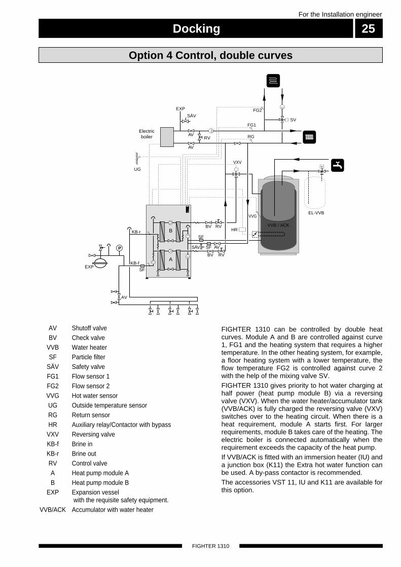
Option 4 Control, double curves
AV Shutoff valveBV Check valve
VVB Water heaterSF Particle filter
SÄV Safety valveFG1 Flow sensor 1FG2 Flow sensor 2VVG Hot water sensorUG Outside temperature sensorRG Return sensorHR Auxiliary relay/Contactor with bypass
VXV Reversing valveKB-f Brine inKB-r Brine outRV Control valveA Heat pump module AB Heat pump module B
EXP Expansion vesselwith the requisite safety equipment.
VVB/ACK Accumulator with water heater
FIGHTER 1310 can be controlled by double heatcurves. Module A and B are controlled against curve1, FG1 and the heating system that requires a highertemperature. In the other heating system, for example,a floor heating system with a lower temperature, theflow temperature FG2 is controlled against curve 2with the help of the mixing valve SV.FIGHTER 1310 gives priority to hot water charging athalf power (heat pump module B) via a reversingvalve (VXV). When the water heater/accumulator tank(VVB/ACK) is fully charged the reversing valve (VXV)switches over to the heating circuit. When there is aheat requirement, module A starts first. For largerrequirements, module B takes care of the heating. Theelectric boiler is connected automatically when therequirement exceeds the capacity of the heat pump. If VVB/ACK is fitted with an immersion heater (IU) anda junction box (K11) the Extra hot water function canbe used. A by-pass contactor is recommended.The accessories VST 11, IU and K11 are available forthis option.
B
A
Cirk.pump
Värmepump
Varmvatten
Tillsatsvärme
Larm
Kontrollera
att vatten
finns i pan-
nan innan
1
R
0
SF
AV
VVG
VXV
RG
FG1
Elkassett/ Elpanna
UG
VVB / ACK
EXP
SF
SF
BV
BV
EL-VVB
T
RV
RV
SÄV
SÄV
P
EXP
AV
RV
AV
AV
FG2
SV
HRKB-r
KB-f
Electricboiler

Electrical connectionFor the Installation engineer
26
FIGHTER 1310
NOTE! Electrical installation and service
must be carried out under thesupervision of a qualified electrician.Electrical installation must be carried
out in accordance with currentstandards and regulations.
Cables to supply the heat pump must run on the left-hand side of the unit.Cables for external sensors must enter on the right-hand side. Cables may exit via the top or the back.
■ A heat pump must not be connected without thepermission of the electricity supplier and must beconnected under the supervision of a qualifiedelectrician.
■ If an automatic fuse unit is used this should have amotor characteristic D (compressor operation). ForMCB size see Technical Specifications.
■ The FIGHTER 1310 does not include an isolatorswitch on the incoming electrical supply. This
Terminal block (9),Incoming electricity
Connecting the supply
Electrical installation
LEK
Svart
Vit
Grå
Brun
Röd
Röd
Grå
Grå
1
R
0
+2-2
maxmin
means the installation must be preceded by a circuit-breaker.■ If an insulation test is to be carried out in the build-
ing, disconnect the heat pump.■ Connect the heat pump to the terminal strip (9)
, 400 V 3-phase, neutral + earth via a distributionboard with fuses. Where there is more than oneheat pump, each unit must have a separate supply.
■ Check the direction of rotation of the brine pump(35) (clockwise as seen from the front cover).
Cable duct for the supply
Cable duct for sensors

Electrical connection 27For the Installation engineer
FIGHTER 1310
■ The outside sensor (15) must be installed in ashaded location on a wall facing north or north-west, where it will not be affected by any morningsun. The sensor is connected by two wires to ter-minals 7 and 8 of terminal block 30 on the relaycard (29). The minimum cable cross section is 0.4mm2 up to 50 metres. Suitable cable types areEKKX or LiYY.
■ If the outside temperature sensor cable runs closeto power cables, screened cable should be used.All conduits should be sealed to avoid condensa-tion in the sensor capsule.
SELV
+ B A –B+ – ARTG EXT.EL.UG
30
15
12345678
Connecting the outside sensor
External control of the electrical supplement and compressor
■ When FIGHTER 1310 controls an external electri-cal supplement disconnection of the entire electri-cal output is achieved by connecting an externalfloating make (NO) contact to terminals 1 and 2 ofterminal block (30).
■ Connect an external, potential free make contact toterminals 1 and 3 on terminal block (30) to discon-nect the entire electrical output, but with the possi-bility to use Extra hot water during the period with-out output.
■ Terminals 2 and 3 should be connected together toblock the compressor as well as the supplement.Terminal 1 is then connected to each side of thecontact that controls the blocking.
Vit
Grå
Brun
Röd
Röd
Grå
Grå
LEK
Svart
Vit
Grå
Brun
Röd
Röd
Grå
Grå
1
R
0
+2-2
maxmin
30
29
SELV
+ B A –B+ – ARTG EXT.EL.UG
30
12345678

Electrical connection
FIGHTER 1310
For the Installation engineer
28
6The four sensors supplied, flow sensor (89), returnsensor (94), hot water sensor (88) (if used) and boilersensor/flow sensor 2 (32) (if used) must be connectedas shown. Sensors must be located in accordance with the cho-sen docking option.The temperature sensors for the flow FG (89) and thereturn RG (94) must make good contact with the mea-suring point to provide the best performance. If a sub-merged tube is not available, use the copper tube sup-plied.
The hot water sensor (88) is placed in the hot waterheater's submerged tube. The boiler sensor isinstalled in the top of the oil-fired boiler. When the boil-er sensor is installed the additional heat is controlledby a mixing valve.
12
34
56
31
32
Connecting temperature sensors supplied with the unit
When more than one FIGHTER 1310 is used, eachunit must receive signals from flow, return and outsidetemperature sensors.This is done by using the accessory TSF 10, whichmeans that only one set of temperature sensors needbe fitted at the measuring points.Separate wiring pairs should be used between TSF 10and each FIGHTER 1310.
Connecting more than one FIGHTER 1310
VVG
RG
FG
VVG
WW-in
WW-outPG/FG 2
Svart
Vit
Grå
Brun
Röd
Röd
Grå
Grå
LEK
Svart
Vit
Grå
Brun
Röd
Röd
Grå
Grå
1
R
0
+2-2
maxmin
31
21
Temperature dropIf a temperature drop is required a make contact in atimer, for example accessory Room unit with clock,should be connected to terminals 1 and 5 on terminalblock 30. The preset value is 8, this can be changedon menu 2b.
8
Electrical connection 29For the Installation engineer
FIGHTER 1310
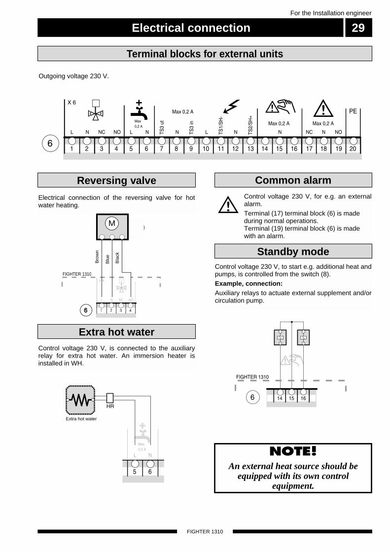
Outgoing voltage 230 V.
Terminal blocks for external units
Standby mode
Reversing valve
Electrical connection of the reversing valve for hotwater heating.
Control voltage 230 V, is connected to the auxiliaryrelay for extra hot water. An immersion heater isinstalled in WH.
Control voltage 230 V, to start e.g. additional heat andpumps, is controlled from the switch (8).Example, connection:Auxiliary relays to actuate external supplement and/orcirculation pump.
Control voltage 230 V, for e.g. an externalalarm. Terminal (17) terminal block (6) is madeduring normal operations. Terminal (19) terminal block (6) is madewith an alarm.
NOTE! An external heat source should be
equipped with its own controlequipment.
Common alarm
1919M
Bru
n
Blå
Sva
rt
FIGHTER 1310
6
N NC NOL
21 3 4
X 6
Extra hot water
Bro
wn
Blu
e
Bla
ck
Extra hot water

Control with oil supplement option 1
FIGHTER 1310
For the Installation engineer
30
Connection
VXV Reversing valve, VST 11PG Boiler sensor
VVG Hot water sensorRG Return sensorFG Flow sensorUG Outside temperature sensorHR Auxiliary relay/Contactor with bypassSV Mixing valve
6 Terminal block, external units9 Terminal block, incoming electric power21 Terminal block, sensor30 Terminal block, relay card31 Terminal block * Extra accessories
12345678
21
43
65
1 2 3 4 5 6 7 8 9 10 1112 13 14 15 16171819 20N L3L2L1
SV
VXV
21
43
65
31
21
69
30
PG
FIGHTER 1310
Panna
PGVVG
RG FG UG
Extra varmvatten
HR
HR
1 2 3 4 5 6
4321
Extra hot water
Boiler
Control with oil supplement option 1 31For the Installation engineer
FIGHTER 1310
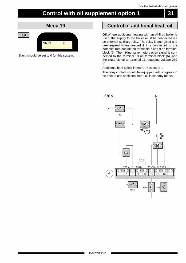
Shunt should be set to 0 for this system.
19
Menu 19
Oil:Where additional heating with an oil-fired boiler isused, the supply to the boiler must be connected viaan external auxiliary relay. The relay is energised anddeenergised when needed if it is connected to thepotential free contact on terminals 7 and 9 on terminalblock (6). The mixing valve motors open signal is con-nected to the terminal 13 on terminal block (6), andthe close signal to terminal 11, outgoing voltage 230V. Additional heat select in menu 14 is set to 1.The relay contact should be equipped with a bypass tobe able to use additional heat, oil in standby mode.
Control of additional heat, oil
230 V N
7
Re 2Re 4 Re 5
TS3 ut N NTS3 in L
Byglas
TS1/SH- TS2/SH+
8 9 10 11 12 136
M
M
Shunt 0
Loop

Control with electrical supplement up to seven steps option 2For the Installation engineer
32
FIGHTER 1310
Connection
VXV Reversing valve, VST 11VVG Hot water sensorRG Return sensorFG Flow sensorUG Outside temperature sensorHR Auxiliary relay/Contactor with bypass
6 Terminal block, external units9 Terminal block, incoming electric power21 Terminal block, sensor30 Terminal block, relay card31 Terminal block37 Motor protection device, brine pump
* Extra accessories
12345678
21
43
65
1 2 3 4 5 6 7 8 9 10 1112 13 14 15 16171819 20N L3L2L1
VXV
21
43
65
31
21
69
30
PG
FIGHTER 1310
Elkassett/Elpanna
VVG RG FG UG
1 2 3 4 5 6
Extra varmvatten
HR
1
2
3
4321
Extra hot water
Electricboiler

Control with electrical supplement up to seven steps option 2 33For the Installation engineer
FIGHTER 1310
Shunt should be set to 0 for this system.
19
Menu 19
Electricity: Additional heat can be controlled fromFIGHTER 1310 in 1, 2, 3 or 7 steps. Control is eitherbinary or linear and utilises 1, 2, or 3 relays inFIGHTER 1310.
1 step: Relay 1 is used.
SH select in menu 14 is set to 3L.
2 step linear: The relays pick up in the order 1, 1+2.Relay 1 and relay 2 are used.
SH select in menu 14 is set to 3L.
3 step linear: The relays pick up in the order 1, 1+2,1+2+3. Relay 1, relay 2 and relay 3 are used. A strapshould be fitted between terminals 9 and 10.
SH select in menu 14 is set to 3L.
3 step binary: Relays 1 and 2 pick up in the order 1,2, 1+2. In this mode FIGHTER 1310 controls 2 powergroups. Relay 1 is used for power group 1 and relay 2is used for power group 2. Power group 2 should begreater than 1.
SH select in menu 14 is set to 3.
7 step binary: Relays 1, 2 and 3 pick up in the order1, 2, 1+2, 3, 3+1, 3+2, 3+2+1. In this mode FIGHTER1310 controls 3 power groups. Relay 1 is use forpower group 1 and relay 2 is used for power group 2,relay 3 is used for power group 3. Power group 2should be greater than 1, and power group 3 shouldbe greater than 1+2. A strap should be fitted betweenterminals 9 and 10. SH select in menu 14 is set to 7.
The electrical connection of the power groups ismade on terminals 11, 13 and 7 on terminal block (6).Switching on and off takes place as set out in the table in the chapterControl (also applies with accessories), menu 18.
Controlling the additional heat,electrical
Shunt 0
LoopRelay 3 Relay 1 Relay 2

Control with two or more Fighter 1310s option 3
FIGHTER 1310
For the Installation engineer
34
Connection
123456
123456
123456
123456
12
123
123
123
123
12345678
21
43
65
1 2 3 4 5 6 7 8 9 10 1112 13 14 15 16171819 20N L3L2L1
21
43
65
31
21
69
30
PG
FIGHTER 1310
1 2 3 4 5 6
VP1
1 2 3 4 5 6 7 8 13b
12345678
21
43
65
1 2 3 4 5 6 7 8 9 10 1112 13 14 15 16171819 20N L3L2L1
SV
VXV
21
43
65
31
21
69
30
PG
FIGHTER 1310
Panna
Extra varmvatten
HR
HR
1 2 3 4 5 6
VP2
1 2 3 4 5 6 7 8 13b
VP4 alt en andra TSF 10
Kanal 1In
Utetemperatur
Kanal 3In
Värmebärare fram
Kanal 4In
Värmebärare retur
FIGHTER 1310 VP3 Kanal 2InReservingång
UG
UG
FGRG
FGRG
UGFGRG
TSF 10
4321
VXV Reversing valve, VST 11PG Boiler sensor
VVG Hot water sensorRG Return sensorFG Flow sensorUG Outside temperature sensorHR Auxiliary relay/Contactor with bypassSV Mixing valve
6 Terminal block, external units9 Terminal block, incoming electric power21 Terminal block, sensor30 Terminal block, relay card31 Terminal block
Extra hot water
Boiler

Control with two or more Fighter 1310s option 3 35For the Installation engineer
FIGHTER 1310
Shunt should be set to 0 for this system.
19
Menu 19
Shunt 0

Control, double curves option 4For the Installation engineer
36
FIGHTER 1310
Connection
12345678
21
43
65
1 2 3 4 5 6 7 8 9 10 1112 13 14 15 16171819 20N L3L2L1
Elkassett/elpanna
SV
VXV
21
43
65
31
21
69
30
PG
FIGHTER 1310
FG2VVG
RG FG UG
1 2 3 4 5 6
HR
Extra varmvatten4321
VXV Shuttle valveVVG Hot water sensorRG Return sensorFG Flow sensorUG Outside temperature sensorHR Auxiliary relay/Contactor with bypass
6 Terminal block, external units9 Terminal block, incoming electric power21 Terminal block, sensor30 Terminal block, relay card31 Terminal block37 Motor protection device, brine pump
Extra hot water
Electricboiler

Control, double curves option 4 37For the Installation engineer
FIGHTER 1310
Shunt should be set to 1 for this system. The option allows a mixing valve in a secondary circuitto be controlled. Setting of control curve 2 is done viamenu 5.This option means additional heat can only be con-trolled with one step (not boiler shunt).
19
Menu 19
If a temperature set back is required a make contact ina timer, for example, accessory Room thermostat RT20, should be connected to terminals 1 and 5 on ter-minal block 30. The preset value is 8, this can bechanged on menu 2b.If the room thermostat, RT 20 is connected a roomsensor cannot be connected.
The temperature sensors for the flow FG (89) FG2(32) and the return RG (94) must make good contactwith the measuring point to provide the best perfor-mance. If a submerged tube is not available, use thecopper tube supplied on the main pipes to the heatingsystem. Secure the copper tube with 2-4 turns of alu-minium tape wound tightly. Now secure the tube usinglashing wire. Insert the temperature sensors and insu-late using two turns of thermal insulating tape.
A mixing valve, if used, is connected to terminal block(6) at terminal 13 SH+, terminal 11 SH- and terminal12 -N. The control voltage is 230 V AC, max 0.5 A.
Control voltage to external supplement is obtained bystrapping terminals 9 and 10. Phase to relays/contac-tors is connected over terminal 7 and terminal 8 is -N.The relay card’s relay contactor is potential free andbreaks max 0.5 A, 230 V AC.
Temperature sensor placement
Connection, external mixing valve
Connection, externaladditional heat
If a system with double curves has been selected, thevalue in menu 19 is set to 1. The heat pump worksagainst curve 1, FG1, and the heating system thatrequires a higher temperature. The flow sensorFG2/PG (32) works against curve 2 and the systemthat needs a lower temperature. The heat pump's sen-sor for the flow and return should remain connected.
Terminal 11 SH-IN and terminal 13 SH-OUT on termi-nal block (6) can be used to control an immersionheater or gas boiler. The relay (Re2) is potential freeand breaks max 0.5 A 230 V AC.
Control, double curves with external mixing valve
Temperature set back
Shunt 1

Commissioning and adjusting
FIGHTER 1310
For the Installation engineer
38
BK / JK
B
A
Cirk.pump
Värmepump
Varmvatten
Tillsatsvärme
Larm
Kontrollera
att vatten
finns i pan-
nan innan
den in-
kopplas.
1
R
0
AV
AV
SF
P
EXP
The heating water system is filled with water until therequired pressure is reached and then vented.
Filling the heating system/heating water system
Filling and venting the brine systemTo fill the brine system, mix about 30% antifreeze withwater in an open container and connect with fillingpump and hoses as illustrated. Close the valve on themain pipe between the service connections and fill bystarting the pump in the filling vessel and let it run untilthe fluid emerges from the return hose. Then start thebrine pump (35) (see Commissioning and adjustingInternal control panel).Check that the direction of rotation of the brine pumpagrees with the arrow on the pump.The brine pump is now operational together with thefilling pump. The fluid can circulate via the mixing ves-sel until fluid, without air, returns to the return hose.
Stop the brine pump and then the filling pump. Cleanthe strainer in the particle filter. Start the filling pumpagain. Open the valve on the main pipe between theservice branches while the filling pump is still opera-tional (to release the air between the branches). Nowshut the valve on the return hose. Pressurise the sys-tem (to max 3 bar) with the filling pump. Now close thefilling valve and stop the filling pump.
AV Shut offSF Particle filterBK Rock collectorJK Soil collector
EXP Level vesselSÄV Safety valve
■ Set the switch to 1.■ Check the settings on the control computer, and
adjust so there is a need of heating.■ Set the switch for the brine (40) and heat water
pumps (39) to position M. Set the switch for com-pressors (25) to position 0, on the inner controlpanel.
■ Check that the brine and heating water pumps arevented and if necessary help the pumps to start.Check that the direction of rotation on the heattransfer pump is right.
■ Go to the ”Brine in, Brine Out” menu. Ensure thatthe temperature corresponds with the ground/rocktemperature, which indicates the brine flow.
■ Set the compressors’ switch (25) in the 1 position.The compressors start, read the brine temperature.The difference between these temperatures oughtto be 2 –5 °C when the system is in balance, withboth compressors running. A high difference indi-cates a high brine flow.
■ Particular attention should be given to the pressurein the brine system when using the heat pump atfirst. Some topping-up may be necessary.
■ Measure the heating water temperature before andafter the condenser. The difference between thesetemperatures ought to be 5 - 10 °C. A high differ-ence could depend on a low heating water flow.
■ Set the brine pump switch (40) in the A position.
■ Set the heating water pump’s switch (39) to posi-tion A or M.
■ Check the internal venting (75) and (77).
■ Fill in the commissioning report on page 2.
■ Set the control computer to suit the needs of thebuilding.
Start-up and inspection
Brine in
Heatingwaterpump A
Heatingwaterpump B
HW returnWW-inWW-out
WW-outBrineout
Brine pump

Commissioning and adjusting 39For the Installation engineer
FIGHTER 1310
Air is initially released from the hot water and ventingmay be necessary. If bubbling sounds can be heardfrom the heat pump, the entire system requires furtherventing. When the system has stabilised (correct pres-sure and all the air removed) the heating controls canbe set at the required value.
Selector switch for brine pumpThe normal position is Auto. The pump runs atthe same time as the compressor. The Man position is used during commission-ing. The pump runs continuously.
Selector switch for heating water pumps A and BIf there is an external circulation pump, thenormal position is Auto. If not, set HWP-A toMan.
Selector switch for compressors A and BThe normal position is 1.
Alarm lamp, motor protection device(compressor)An alarm lamp indicates that the motor protec-tion device has tripped. In the event of a faultset the switch (25) to 0.
Check that all air is removed from the brine system byopening the venting valves. The pressure in the brinecircuit is checked with the help of pressure gauges.Filling of brine system is done by pumping readymixed brine through the filling valve.Venting and filling are repeated until all the air hasbeen removed and the correct pressure (0.5 - 3 bar)has been obtained.
Readjustment, brine system
Internal control panelInternal venting valves
Readjustment, heating water system
LEK
Svart
Vit
Grå
Brun
Röd
Röd
Grå
Grå
1
R
0
+2-2
maxmin
25
25
40
40
39
36
36
39
7577

Setting the heating controls
FIGHTER 1310
40For the Installation engineer
FIGHTER 1310
The heating control system of the FIGHTER 1310 iscontrolled by the outside temperature. This means theflow temperature is regulated in relation to the currentoutdoor temperature.The relationship between the outdoor temperatureand the flow temperature is set using the computer,see Controls Setting the heating.The diagram is based on the dimensioned outdoortemperature in the area and the dimensioned flowtemperature of the heating system. When these twovalues meet, the heating control’s curve slope can beread.The Increase/Reduce heating knob (heating curve off-set) can then be set. A suitable value for floor heatingis -1 and for radiator systems -2.
30
40
50
60
70°C
FR
AM
LE
DN
ING
ST
EM
PE
RA
TU
R
- 40 °C
UTETEMPERATUR
- 10010 - 20 - 30
15 14 13 12 11 10 9
8
7
6
5
4
3
2
1
KURVLUTNING
- 5
+ 5
PARALLELLFÖRFLYTTNING
15 14 13 12 11 10
9
8
7
6
5
4
3
2
1
- 40 °C
UTETEMPERATUR
- 10010
- 5
+ 5
30
40
50
60
70°C
FR
AM
LE
DN
ING
ST
EM
PE
RA
TU
R
- 20 - 30
PARALLELLFÖRFLYTTNING
KURVLUTNING
1514 13 12 11 108
7
6
5
4
3
2
1
- 40 °C
UTETEMPERATUR
- 10010
- 5
+ 5
30
40
50
60
70°C
FR
AM
LE
DN
ING
ST
EM
PE
RA
TU
R
- 20 - 30
PARALLELLFÖRFLYTTNING
9
KURVLUTNING
Heating curve offset 0
Heating curve offset -2Setting using diagrams
Heating curve offset +2
HEATING CURVE
HEATING CURVE
HEATING CURVE
HEATING CURVEOFFSET
HEATING CURVEOFFSET
FLO
W T
EMPE
RA
TUR
EFL
OW
TEM
PER
ATU
RE
FLO
W T
EMPE
RA
TUR
E
OUTSIDE TEMPERATURE
OUTSIDE TEMPERATURE
HEATING CURVEOFFSET
NOTE! Where more than one heat pump is
used, Heating curve and Heating curve offset must be set the
same on all units.
OUTSIDE TEMPERATURE

Circuit diagram 41For the Installation engineer
FIGHTER 1310
P
X9L1
X9L2
X9L3
X2911A
3A2A
4B T5AH
6B5B
X292
X2914
X13b1
X13b2
X13b3
X13b4
Re3
Re9
Re1
Re2
Re4
Re5
Re7
Re8
X925
X2911
X2913
X134
X132
X133
X131
X136
X137
X1310
X138
X135
X139
X294
X614 X6
15X616
X617
X619
X67
X69
X610
X611
X613
X65
X64
X63
X61
X62
X66
X612
X68
X618
X295
X297
X299
X2912
X296
X2916
X2919
X620PE
X2915
X2917
X2920
X2921
X2922
X2923
5
31
2 4 6
6
42
R
SC
X293
X9N PE
X2924
X13b5
2
833a
P
33b 26a 26b 37
25a
25b
40
69a
69a
69b
39a
39b
69b
68
68
36b
36a
69a
1 3 568
26a
69a
Re6 X918
X2910
X610
X13b5
69b
38
16
6
19
27a
10R
5
31
6
42
R
SC
69b 26b 27b
5
31
6
42
R
SC
38 37 35
Reserv-läge
Larm
OljaTS3
TS1/S4-
Ts2/S4+
XVV
VXVentil
L3L2L1
X136,6
97a
97b

Component placement
FIGHTER 1310
For the Installation engineer
42
LEK
LEK
77
87
16
19
35
4
86
71
73
72
70
76
78
5
96
96
75
LEK
65
17
27
7
42
48
4118
2833
LEK
LEK
Svart
Vit
Grå
Brun
Röd
Röd
Grå
Grå
1
R
0
+2-2
maxmin
38682 21 30 29 34
813a
3169b
9
6
25b 13b36b
36a
39b
40
25a
39a
26b37 26a
97b9597a 69a

List of components 43For the Installation engineer
FIGHTER 1310
2 Miniature circuit breaker4 Brine In connection, KB-f 5 Brine Out connection, KB-r 6 Terminal blocks, external units
7 a, b Service connection, high pressure8 Switch, 1 0 R9 Terminal block, incoming electricity
13 a, b Terminal block, pumps, high pressurepressostat
15 Outdoor sensor, connection16 Heating water pump, module A17 a, b Evaporator18 a, b Condenser19 Heating water pump, module B21 Terminal block, sensor25 a, b Switch, compressor26 a, b Motor protection, including reset27 a, b Compressor28 a, b Operating pressostat29 Relay card with power supply unit30 Terminal block, relay card31 Terminal block32 Boiler sensor33 a, b High pressure pressostat34 Computer with display, including sensor35 Brine pump36 a, b Indicator lamp, motor protection device,
compressor37 Motor protection device, brine pump38 Contactor, brine pump
39 a, b Switch, heating water pump40 Switch, brine pump41 a, b Low pressure pressostat42 a, b Service connection, low pressure48 a, b Expansion valve63 Particle filter65 a, b Drying filter68 Contactor, compressor start69 a, b Contactor, compressor operation70 Heating water flow from module A, WW-out71 Connection, heating water return, WW-in72 Flow line to water heater / Heating water flow
WW-in from module B73 Return line from water heater, HW return75 Venting for the heating water system76 Drain for heating water system77 Venting valve, brine system78 Drain for brine system86 Temperature sensor, KB-f, Brine in 87 Temperature sensor, KB-r, Brine out88 Temperature sensor, hot water89 Temperature sensor, WW-out94 Temperature sensor WW-in95 Type plate96 Type plate, cooling section97 a,b Starting current limiter

Dimensions44
FIGHTER 1310
For the Installation engineer
30 -
50
Cir
k.pu
mp
Vär
mep
ump
Var
mva
tten
Tills
atsv
ärm
e
Larm
Kon
trol
lera
at
t vat
ten
finns
i pa
n-na
n in
nan
den
in-
kopp
las.
1 R0
600
600140
80
120
180
1475
110
540
725 81
5 1145
Cirk.pump
Värmepump
Varmvatten
Tillsatsvärme
Larm
Kontrollera att vatten finns i pan-nan innan den in-kopplas.
1
R
0
600
KB-r (ut) Ø42
KB-f (in), Ø42
VV-retur, Ø28
VB-r (in), Ø35
VV-Fram /VB-Fram (B) Ø28
VB-Fram (A), Ø28
Kabelintag, givare
Kabelintag, starkström (matning)
An area of 800 mm isrequired in front ofthe heat pump forservice work.
Leave 800 mm of space freeto the right and left of theheat pump for servicing.
Cable gland, incomingsupply
Cable gland, sensors
Dimensions and setting-out coordinates
WW-out (B) Ø28
WW-out (A) Ø28
Brine out Ø42
Brine In Ø42

Accessories 45
FIGHTER 1310
For the Installation engineer
Hot water control VST 11Art-No: 089152
Reversing valve, Cu-pipe Ø28(Max recommended
charge power, 15 kW)
Temperaturesignal distributor
TSF 10Use 2-4
FIGHTER 1310
RG20
Art-No: 018823
Room sensor RG 20Art-No: 418345
Art-No:3 kW 0180846 kW 0180889 kW 018090
Immersion heater IU(3 kW, 6 kW and 9 kW)
IU
Room unit RT 20
K11Art-No: 418645
Junction box K11with thermostat and
overheating protectionArt-No: 018893
LEK
LEK
LE
K
21
34
5678 9

Technical specificationsFor the Installation engineer
46
FIGHTER 1310
The enclosed kit is located behind the front panel atthe upper module.
IP 21
Size 20 25 30
Max operating current, compressor (A) 2 x 7.9 2 x 9 2 x 11
Refrigerant quantity (R407C) (kg) 2 x 2.4 2 x 2.5 2 x 2.6
Available pressure for brine system (kPa) 130 160 135
Operating temperature brine system (°C) -10 – +20
Max temperature (Supply/return pipes) (°C) 60/50
Pressostat HP open/closed values (bar) 27/20
LEK
NIBE AB
Utetemperatur givare
Outdoor temperature sensor
Aussentemperatur fühler
Artikel 018764
32
88
89
94
15
Temperature sensors with probesArt-No 418027
* Compressor power only** Refers to the brine flow temperature/heat water flow temperature in accordance with EN 255.
Delivered/supplied power* at 0/35 °C ** 23,3/4,9 29,3/6,2 34,0/7,5
Delivered/supplied power* at 0/50 °C ** (kW) 19,8/5,7 25,3/7,2 29,6/8,6
Starting current (A) 30 30 30
Power, brine pump, three-phase (W) 370 600 600
Brine flow (l/s) 1,3 1,5 1,7
Max pressure brine system (bar) 3
Heating water flow (l/s) 2 x 0.26 2 x 0.31 2 x 0.36
Operating pressostat open/closed value (bar) 24/20
Pressostat LP open/closed values (bar) 1,5/3
Weight (kg) 360 365 370
Particle filterArt-No.024076 (R25) 1 024077 (R32) 1 024194 (R40) 1
63
Outside sensorArt-No 018764
LE
K
LE
K
AJ
Tubes for sensorsArt-No 008392
Thermal insulating tapeArt-No 025910
Heating pipe pasteArt-No 021081
Aluminium tapeArt-No 025179
Hoses with seals(heating water flow, R25
male/female)Art-No. 424088
Protection, (motor charact./slow)(A) (A) 25
Connection, brine ext Ø (mm) 42
Power, heating water pump, single-phase (W) 2 x 170
Connection, heating water ext Ø (mm) 2 x 28/35
Operating voltage (V) 3 x 400+N
Enclosure class IP 21
Enclosed kit

Actions with operating disturbances 47For the Installation engineer
FIGHTER 1310
Cause: Incorrect setting of the Curve slope and/orIncrease/reduce heat.
Action: Adjust the setting.
High room temperature
Cause: Large amount of hot water drawn off.Action: Wait until the water heater reheats.
Cause: Compressor and/or immersion heater does notheat up.
Action: Check and replace any blown circuit and mainfuses.
Cause: Too low start temperature setting on the con-trol computer (34).
Action: Adjust the hot water setting HWstart, see Avail-able information and on-display settings menu3
Cause: Possible earth circuit-breaker tripped.Action: Reset the earth circuit-breaker, if the earth cir-
cuit-breaker trips repeatedly, call an electrician.
Cause: Compressor and electric element do not heatup.
Action: Check and replace the any blown circuit andmain fuses.
Cause: The compressor does not start because of atoo low value set on the heating curve.
Action: Check and possibly raise Increase/reduce heat(knob on the front panel) or Curve slope.
Cause: The compressor is not running due to trippedinternal overheating protection.
Action: Automatic resetting after cooling for a fewhours.
Cause: Possible earth circuit-breaker tripped.Action: Reset the earth circuit-breaker, if the earth cir-
cuit-breaker trips repeatedly, call an electrician.
Low hot water temperature orno hot water
Low room temperature
In the event of malfunction or operating disturbances first check the points below:
NOTE! As FIGHTER 1310 can be connected
to a large number of external unitseven these should be checked.
Alarm lamp flashes and the textHP/MSalarm is displayedCause: Bad circulation in the heating water circuit.Action: Check the heating water pump (16). Open
any radiator thermostats. Check that the parti-cle filter is not blocked.
Once the fault cause has been rectified set switch (8)to 0 and then to 1. If the alarm lamp still flashes themotor cut-out has tripped due to the following causes.
Cause: Dropped phase or temporary mainsdisturbance.
Action: Check the fuses.
Cause: Overloaded compressor(27).Action: Call qualified service personnel.
Cause: Mechanical fault on the compressor (27).Action: Call qualified service personnel.
Cause: Faulty motor protection (26).Action: Call qualified service personnel.
Cause: Fine-wire fuse on the relay card has blown.Action: Replace the fuse.
Alarm lamp flashes and the text LPalarm is displayedCause: Start up of a cold installationAction: Use Electric boiler mode.
Cause: Bad circulation in brine system due to inferiorventing/low pressure or ice (if ice has formedthe brine pump (35) will be warm).
Action: Vent and top up the fluid. Wait a few hours.
Cause: Brine pump (35) malfunction.Action: Check the brine pump.
Cause: Lack of refrigerant or other fault in the coolingcircuit.
Action: Call qualified service personnel.
Cause: Blocked evaporator due to too low antifreezeconcentration.
Action: Check the brine freezing point.After taking action, check, on the display, that the dif-ference between Brine in and Brine out is 2 - 5 °Cthe compressor is then operational. (See ControlInformation available on the display, menu 4.) Once the fault cause has been rectified set switch (8)to 0 and then to 1.
Ifthe operating disturbance cannot berectified by means of the above a
installation engineer should be called.
Indications
NOTE! The fault status must not be repeatedlyreset, as there is a risk of overheating
the motor windings.

Actions with operating disturbancesFor the Installation engineer
48
FIGHTER 1310
Close the shut-off valves in heating water system.Now open the drain valve (76). A little water, possiblywarm, runs out. In order to empty the entire heatingwater side the coupling that joins the heating waterside and the connection on the heat pump ”WW-out”should be loosened a little to let in air so that theremaining water can run out. When the heating wateris empty the requisite service can be carried out.
When performing a service on the brine system theclosest shut off valves are closed on both sides.Draining of the fluid can then be done using the drainvalve (78).
Draining, brine systemDraining, heating water system
■ Shut down FIGHTER 1310 by turning the switch(8) to 0.
■ Open the front cover.
■ Loosen the venting screw with a screwdriver. Holda cloth around the screwdriver blade as a certainamount of water may run out.
■ Insert a screwdriver and turn the pump rotor.
■ Screw in the venting screw.
■ Start FIGHTER 1310 and check whether the circu-lation pump runs.
It is usually easier to start the circulation pump withFIGHTER 1310 running, switch (8) set to 1. If helpingthe circulation pump to start is performed with FIGHTER 1310 running, be prepared for the screw-driver to jerk when the pump starts.
Helping the circulation pump to start
Luftningsskruv
16
LE
K
GR
UN
DFO
SType
UP
S25 -
60
130
P/N
:59526447
230V
-
HE
JS
AN
PC
;0017N
IBD
K50H
z
IP 44
TF
110
Cla
ss H
Max. 1
0bar
2.5
uF
45
0.2
065
0.3
090
0.4
0
1m(A
)P,
(W)
■ Set switch (8) to 0.
■ Close the shut-off valves outside the heat pump.
■ Drain the part of the circuit where the pump to becleaned is located, the heating water pump or thebrine pump.
■ Loosen the venting screw.
■ Remove the drive side from pump housing by loos-ening the two screws. Now dismantle the drive side(fig. A).
■ Remove the rotor unit (including pump housing) bycarefully pulling the pump rotor. If it sits firmly, itcan be loosened by knocking the rear of the shaft(fig. B).
■ Clean inside the stator can using a cleaning agent(fig. C).
■ Also clean the rotor unit using the cleaning agentand lubricate the O-ring with, for example, a soapsolution (fig. D).
■ Refit the rotor unit.
■ Refit the drive side (the flat packing is best placedon the pump housing).
■ Open the shut-off valves.
■ Set switch (8) to 1.
Cleaning the circulation pump
Rotor unit
Drive side
A
LEK
GR
UN
DFO
STyp
eU
PS
25
- 6
01
30
P/N
:59
52
64
47
23
0V
-
HE
JS
AN
PC
;00
17
NIB
DK
50
Hz
IP
44
TF
1
10
Cla
ss
HM
ax. 1
0b
ar
2.5
uF
45
0.2
06
50
.30
90
0.4
0
1m(A
)P,
(W)
B
LEK
C
LEKD
Venting screw


NIBE ABSWEDEN
R
Tel: +46 - (0)433 - 73 000Fax: +46 - (0)433 - 73 190www.nibe.com
Box 14Järnvägsgatan 40SE-285 21 MARKARYD