r-880b service manualmichel92.free.fr/schemas/fours_%b5ondes/sharp/r8xxx/r880b.pdf · 4. when the...
TRANSCRIPT

R-880B
TABLE OF CONTENTSPage
CAUTION, MICROWAVE RADIATION.................................................................................................... 1WARNING.................................................................................................................................................1PRODUCT SPECIFICATIONS ................................................................................................................ 2GENERAL INFORMATION.......................................................................................................................2APPEARANCE VIEW .............................................................................................................................. 3OPERATION SEQUENCE....................................................................................................................... 4FUNCTION OF IMPORTANT COMPONENTS ....................................................................................... 8SERVICING ..............................................................................................................................................8TROUBLESHOOTING GUIDE ............................................................................................................... 10TEST PROCEDURE.............................................................................................................................. 12TOUCH CONTROL PANEL ASSEMBLY ..............................................................................................20COMPONENT REPLACEMENT AND ADJUSTMENT PROCEDURE .................................................. 26MICROWAVE MEASUREMENT ........................................................................................................... 33WIRING DIAGRAM................................................................................................................................ 34PICTORIAL DIAGRAM .......................................................................................................................... 38POWER UNIT CIRCUIT .........................................................................................................................39CONTROL PANEL CIRCUIT ..................................................................................................................40PRINTED WIRING BOARD ....................................................................................................................41PARTS LIST .......................................................................................................................................... 42
S9839R880BPM/
DOUBLE GRILLCONVECTION
MICROWAVE OVEN
MODEL R-880B
In interests of user-safety the oven should be restored to its originalcondition and only parts identical to those specified should be used.
SERVICE MANUAL
SHARP CORPORATION
DOUBLE GRILL CONVECTIONSensor
COOKHELP
HELP
Info Display
CONVEC REHEATGRILL
POWERLEVEL
MIX
MIXLESSMORE
STOPCLEAR
INSTANT COOKSTART
CLOCK
SENSOR INSTANT ACTION
40˚ C 70˚ C 130˚ C 150˚ C 160˚ C
180˚ C 200˚ C 220˚ C 230˚ C 250˚ C
1 2 3 4 56 7 8 9 0
MULTICOOK
FreshVegetables Jacket
PotatoFrozen
Vegetables
Reheat Pie
Rice Pasta
REHEATSENSOR
CONVENIENCE/PIZZA
EASY DEFPST

R-880B

R-880B
1
SERVICE MANUAL
DOUBLE GRILLCONVECTION
MICROWAVE OVEN
R-880B
GENERAL IMPORTANT INFORMATION
This Manual has been prepared to provide Sharp Corp. Serviceengineers with Operation and Service Information.
It is recommended that service engineers carefully study the entiretext of this manual, so they will be qualified to render satisfactorycustomer service.
CAUTIONMICROWAVE RADIATION
Service engineers should not be exposed to the microwaveenergy which may radiate from the magnetron or other micro-wave generating devices if it is improperly used or connected.All input and output microwave connections, waveguides, flangesand gaskets must be secured. Never operate the device withouta microwave energy absorbing load attached. Never look intoan open waveguide or antenna while the device is energized.
WARNING
Never operate the oven until the following points are ensured.(A) The door is tightly closed.(B) The door brackets and hinges are not defective.(C) The door packing is not damaged.(D) The door is not deformed or warped.(E) There is not any other visible damage with the oven.
Servicing and repair work must be carried out only by trainedservice engineers.
All the parts marked "*" on parts list are used at voltages more than250V.
Removal of the outer wrap gives access to potentials above 250V.
All the parts marked "∆" on parts list may cause undue microwaveexposure, by themselves, or when they are damaged, loosened orremoved.
Never operate the Top and/ or Bottom heater with the ovenouter cabinet removed. (Because air flow is eliminated, and theexcess heat generated on adjacent components). It can causepermanent damage or a fire.
SHARP CORPORATION
OSAKA, JAPAN
PRODUCT SPECIFICATIONS
GENERAL INFORMATION
APPEARANCE VIEW
OPERATING SEQUENCE
FUNCTION OF IMPORTANTCOMPONENTS
SERVICING ANDTROUBLESHOOTING GUIDE
TEST PROCEDURE
TOUCH CONTROL PANEL
COMPONENT REPLACEMENTAND ADJUSTMENT PROCEDURE
MICROWAVE MEASUREMENT
WIRING DIAGRAM
PARTS LIST

2
R-880B
GENERAL INFORMATION
WARNING
THIS APPLIANCE MUST BE EARTHED
IMPORTANT
THE WIRES IN THIS MAINS LEAD ARE COLOURED IN ACCORDANCE WITH THE FOLLOWING CODE:
GREEN-AND-YELLOW : EARTHBLUE : NEUTRALBROWN : LIVE
PRODUCT DESCRIPTION
SPECIFICATION
ITEM DESCRIPTION
Power Requirements 220 Volts50 HertzSingle phase, 3 wire earthed
Power Consumption Microwave cooking 1.6 kW
Top Heater mode 1.3 kWGrill cooking Bottom heater mode 0.9 kW
Top and Bottom heater mode 2.1 kW
Convection cooking 2.1 kWPower Output 900 W nominal of RF microwave energy (measured by method of IEC 705)
Operating frequency 2450 MHzGrill heater Power Output (Top heater) 1200 W (600 W x 2)
Bottom heater Power Output 800 W
Case Dimensions Width 520 mmHeight 309 mm including footDepth 502 mm
Cooking Cavity Dimensions Width 352 mmHeight 189 mmDepth 368 mm
Turntable diameter 325 mmControl Complement Touch Control System
Clock (1:00 - 12:59) / Timer (0 - 99 minutes and 99 seconds)Microwave Power for Variable Cooking
Repetition Rate;100% ................................................... Full power throughout the cooking time70% ..................................................................... approx. 70% of FULL Power50% ..................................................................... approx. 50% of FULL Power30% ..................................................................... approx. 30% of FULL Power10% ..................................................................... approx. 10% of FULL PowerMix cookingHigh Mix Top Grill ............................... Top heater with 70% microwave powerLow Mix Top Grill ................................ Top heater with 50% microwave powerHigh Mix Bottom Grill ........................ Bottom heater with 70% microwave powerLow Mix Bottom Grill ......................... Bottom heater with 10% microwave powerGrill Cooking ............... Top heater mode/ Buttom heater mode/ Top and Buttom
heater modeConvection cooking.......................................... 40˚C to 250˚C temperature control
HELP pad, MULTI COOK pad, CONVIENIENCE/PIZZA padREHEAT SENSOR pad, EASY DEFROST padSENSOR INSTANT ACTION pads, MIX pad, GRILL pad, CONVEC padREHEAT pad, LESS (")/MORE (') pads, POWER LEVEL padNUMBER AND TEMPERATURE pads, STOP/CLEAR padCLOCK pad, INSTANT COOK/START pad
Set Weight Approx. 20 kg

R-880B
3
APPEARANCE VIEW
1. TOP HEATER SYMBOLThe symbol will light when the top heater is in use.
2. BOTTOM HEATER SYMBOLThe symbol will light when the bottom heater is in use.
3. CONVECTION SYMBOLThe symbol will light during convection cooking.
A. HELP PADPress to select auto start, information guide on/off, child lock,demonstration modes or info on pads.Press to obtain cooking information.
B. MULTI COOK PADPress to select Multi Cook mode.
C. CONVIENIENCE/PIZZA PADPress to select 6 popular menus.
D. REHEAT SENSOR PADPress to select 3 popular Re-heat menus.
E. EASY DEFROST PADPress to defrost meat by entering weight.
F. SENSOR INSTANT ACTION PADPress once to cook or reheat 6 popular menus.
G. MIX PADPress to select Mix cooking.
H. GRILL PADPress to select Grill cooking.
I. CONVEC PADPress to select Convection cooking.
J. REHEAT PADPress to reheat the oven prior to cooking.
K. LESS (")/MORE (') padsPress to adjust the doneness of food in one minute incrementsduring cooking or to increase/ decrease the time whilst pro-gramming the automatic operations.
L. POWER LEVEL PADPress to select microwave power setting. If not pressed, HIGHis automatically selected.
M. NUMBER AND TEMPERATURE PADSPress to enter cooking times, clock time, convection tempera-ture, weight or quantity of food.
N. STOP/CLEAR PADPress to clear during programming. Press once to stop opera-tion of oven during cooking; Press twice to cancel cookingprogramme.
O. CLOCK PADPress to set clock time.
P. INSTANT COOK/START PADPress once to cook for 1 minute on HIGH orincrease by 1 minute multiples each time thispad is pressed during manual cooking. Pressto start oven after setting programs.
OVEN1. Oven lamp2. Top heaters (Grill heaters)3. See through door4. Door hinges5. Door safety latches6. Door seals and sealing surfaces7. Bottom heater8. Oven cavity9. Turntable motor shaft10.Ventilation openings11.Waveguide cover12.Door opening button13.Control panel14.Digital display15.Power supply cord16.Outer cabinet17.Menu label
Turntable Turntable support
High rack
Low rack
Turntable motor shaft
Bottom heater
NOTE:1. Ensure that the bottom heater is in the lowest
position as shown the figure, as it is possibleto move it up and down to help with cleaning.
2. Place the turntable support over the turnta-ble motor shaft on the floor of the cavity.
3. Then place the turntable on to the turntablesupport.
TOUCH CONTROL PANEL
1
4 u
3
0
0
0
0
5
5
2
6 w7
98q e
rt
y
COOKHELP
HELPInfo Display
CONVEC REHEATGRILL
POWERLEVEL
MIX
LESS MORE
STOPCLEAR
INSTANT COOKSTARTCLOCK
SENSOR INSTANT ACTION
40˚ C 70˚ C 130˚ C 150˚ C 160˚ C
180˚ C 200˚ C 220˚ C 230˚ C 250˚ C
1 2 3 4 56 7 8 9 0
MULTICOOK
FreshVegetables
JacketPotato
FrozenVegetables
Reheat Pie
Rice Pasta
REHEATSENSOR
CONVENIENCE/PIZZA
EASY DEFPST
INDICATOR
1
23A
B
D
G
M
N
O
H
K
C
E
IJ
L
P
F

4
R-880B
OPERATION SEQUENCE
OFF CONDITIONClosing the door activates the 1st. latch switch and 2nd.interlock relay control switch.
IMPORTANT:When the oven door is closed, the contacts COM-NCof the monitor switch must be open. When the mi-crowave oven is plugged in a wall outlet (220V 50Hz),the line voltage is supplied to the noise filter and thecontrol unit.
Figure O-1 on page 341. The oven display will show " SHARP MICRO- WAVE
OVEN " .2. Press the STOP/CLEAR pad. The oven display will
show " : ".3. Set the clock as follows.
3-1. Press the CLOCK pad once.3-2. Enter the time of day by perssing the number
pads.3-3. Start the clock by pressing the CLOCK pad.
NOTE:1. If you do not set the clock, " : " will appear on the
display. When the operation of the oven is finished, " :" will appear on the display instead of the time of day.
2. The oven can be also used when the clock is not set.3. When the oven door is opened, the oven lamp does not
come on.
MICROWAVE COOKING CONDITION100% (HIGH) COOKINGEnter a desired cooking time by pressing the number padsand start the oven by pressing START pad.
Function sequence Figure O-2 on page 34CONNECTED COMPONENTS RELAYConvection motor RY1High voltage transformer RY2Grill heater (Top) RY3Bottom heater RY4
Fan motor, RY5Oven lamp, Turntable motor RY6
1. The line voltage is supplied to the primary winding ofthe high voltage transformer. The voltage is convertedto about 3.3 volts A.C. output on the filament windingand high voltage of approximately 2000 volts A.C. onthe secondary winding.
2. The filament winding voltage (3.3 volts) heats themagnetron filament and the high voltage (2000 volts) issent to the voltage doubling circuit, where it is doubledto negative voltage of approximately 4000 volts D.C..
3. The 2450 MHz microwave energy produced in themagnetron generates a wave length of 12.24 cm. Thisenergy is channelled through the waveguide (transportchannel) into the oven cavity, where the food is placedto be cooked.
4. When the cooking time is up, a signal tone is heard andthe relays RY2 + RY5 + RY6 go back to their homeposition. The circuits to the oven lamp, high voltagetransformer, fan motor and turntable motor are cut off.
5. When the oven door is opened during a cooking cycle,the switches come to the following condition.
Switch Contact ConditionDuring Oven DoorCooking Open(No cooking)
1st. latch switch COM-NO Closed Opened2nd. interlock relaycontrol switch COM-NO Closed Opened
Monitor Switch COM-NC Opened Closed
The circuit to the high voltage transformer, fan motor, ovenlamp and turntable motor are cut off when the 1st. latchswitch and 2nd. interlock relay control switch are madeopen. Shown in the display is remaining time.6. MONITOR SWITCH CIRCUIT
The monitor switch is mechanically controlled by theoven door, and monitors the operation of the 1st. latchswitch and the 2nd. interlock relay RY2.
6-1. When the oven door is opened during or after thecycle of a cooking program, the 1st. latch switch and2nd. interlock relay control switch must open theircontacts first. After that the contacts (COM-NC) of themonitor switch can be closed.
6-2. When the oven door is closed, the contacts (COM-NC) of the monitor switch must be opened. After thatthe contacts of the 1st. latch switch and 2nd. interlockrelay control switch are closed.
6-3. When the oven door is opened and the contacts of the1st. latch switch and the 2nd. interlock relay RY2remain closed, the fuse M10A will blow, because themonitor switch is closed and a short circuit is caused.
70% (MEDIUM HIGH), 50% (MEDIUM), 30% (ME-DIUM LOW), 10% (LOW COOKING)When the microwave oven is preset for variable cookingpower, the line voltage is supplied to the high voltagetransformer intermittently within a 32-second time basethrough the relay contact which is coupled with the cur-rent-limiting relay RY2. The following levels of microwavepower are given.
SETTING
Note: The On/Off time ratio does not exactly correspondto the percentage of microwave power, becauseapprox. 2 seconds are needed for heating up themagnetron filament.
GRILL COOKING CONDITIONSThe oven has three grill cooking condition. They are theTOP GRILL mode, BOTTOM GRILL mode and TOP ANDBOTTOM GRILL mode.
TOP GRILL MODE
In this mode, the food is cooked by the top heaters. Pressthe GRILL pad once and then enter the cooking time bypressing the number pads. When the START pad ispressed, the following operations occur:
Figure O-3(a) on page 35
100%32 sec. ON
Approx. 100%
70%24 sec. ON 8 sec. OFF
Approx. 70%
50%18 sec. ON 14 sec. OFF
Approx. 50%
30%12 sec. ON 20 sec. OFF
Approx. 30%
10%6 sec. ON 26 sec. OFF
Approx. 10%

R-880B
5
1. The relay RY3 + RY5 + RY6 are energized.2. The numbers of the digital read-out start the count
down to zero.3. Then the top heaters, turntable motor, oven lamp and
fan motor are energized.4. Now, the food is grilled by the top heaters.5. Upon completion of the selected cooking time, audible
signal sounds and the contacts of relays RY3 + RY6are opened, then the top heaters, turntable motor andoven lamp are de-energized. But the relay RY5 staysclosed and the fan motor operates for 5 minutes. But ifthe cooking time is less than 2 minutes the relay RY5will not stay close.
BOTTOM GRILL MODE
In this mode, the food is cooked by the bottom heater.Press the GRILL pad twice and then enter the cooking timeby pressing the number pads. When the START pad ispressed, the following operations occur:
Figure O-3(b) on page 351. The relay RY4 + RY5 + RY6 are energized.2. The numbers of the digital read-out start the count
down to zero.3. Then the bottom heater, turntable motor, oven lamp
and fan motor are energized.4. Now, the food is grilled by the bottom heater.5. Upon completion of the selected cooking time, audible
signal sounds and the contacts of relays RY4 + RY6are opened, then the bottom heating elements, turnta-ble motor and oven lamp are de-energized. But therelay RY5 stays closed and the fan motor operates for5 minutes. But if the cooking time is less than 2 minutesthe relay RY5 will not stay close.
TOP AND BOTTOM GRILL MODE
In this mode, the food is cooked by both the top heatersand bottom heater. Press the GRILL pad three times andthen enter the cooking time by pressing the number pads.When the START pad is pressed, the following operationsoccur:
Figure O-3(c) on page 361. The relay RY3 + RY4 + RY5 + RY6 are energized.2. The numbers of the digital read-out start the count
down to zero.3. Then the top heaters, bottom heater, turntable motor,
oven lamp and fan motor are energized.4. Now, the food is grilled by the top heaters and the
bottom heater.5. Upon completion of the selected cooking time, audible
signal sounds and the contacts of relays RY3 + RY4 +RY6 are opened, then the top heating elements, bot-tom heating element, turntable motor and oven lampare de-energized. But the relay RY5 stays closed andthe fan motor operates for 5 minutes. But if the cookingtime is less than 2 minutes the relay RY5 will not stayclosed.
GRILL MIX COOKING CONDITIONThe oven will cook food by supplying grill heaters (topheaters or Bottom heater) and microwave energy alter-nately within a 48 seconds time base. And the oven hasfour programmed cooking mode.
HIGH MIX TOP GRILL MODE AND LOW MIX TOPGRILL MODE
In these modes, the food is cooked by the top heaters andthe microwave energy. Press the MIX pad once for HIGHMIX TOP GRILL mode. Press the MIX pad twice for LOWMIX TOP GRILL mode. And then enter the cooking timeby pressing the number pads. When the START pad ispressed, the following operations occur:
Figure O-5(a) on page 371. The relay RY5 + RY6 are energized.2. The numbers of the digital read-out start the count
down to zero.3. The turntable motor, oven lamp and fan motor are
energized.4. The relay RY2 + RY3 are energized alternately within
a 48 seconds time base by the control unit.5. The top heaters operate through the relay RY3 is
energized. And the high voltage transformer operatesthrough the relay RY2 is energized.
6. The relationship between the top heating elements andmagnetron operations are as follows.
Note: The On/Off time ratio does not exactly correspondto the percentage of microwave power, becauseapprox. 2 seconds are needed for heating up themagnetron filament.
7. Upon completion of the selected cooking time, audiblesignal sounds and the contacts of relays RY2 + RY3 +RY6 are opened, then the top heaters, high voltagetransformer, turntable motor and oven lamp are de-energized. At the end of the convection cycle, if thecavity air temperature is above 120˚C, the circuit toRY5 will be maintained (by the thermistor circuit) tocontinue operation of the cooling fan motor until thetemperature drops below 104˚C, at which time therelay will be de0energized, turning off the fan motor.
HIGH MIX BOTTOM GRILL MODE AND LOW MIX BOT-TOM GRILL MODE
In these modes, the food is cooked by the bottom heaterand the microwave energy. Press the MIX pad three (3)times for HIGH MIX BOTTOM GRILL mode. Press the MIXpad four (4) times for LOW MIX BOTTOM GRILL mode.And then enter the cooking time by pressing the numberpads. When the START pad is pressed, the followingoperations occur:
Figure O-5(b) on page 371. The relay RY5 + RY6 are energized.2. The numbers of the digital read-out start the count
down to zero.3. The turntable motor, oven lamp and fan motor are
36 SEC. 12 SEC.
LOW MIX TOP GRILL mode
HIGH MIX TOP GRILL mode
MICROWAVE POWER = APPROX. 70%
MICROWAVE POWER = APPROX. 50%
ON
OFF
OFF
ON
26 SEC. 22 SEC.
ON
OFF
OFF
ON
(MICRO.)
(MICRO.)
TOP HEATERS
TOP HEATERS

6
R-880B
energized.4. The relay RY2 + RY4 are energized alternately within
a 48 seconds time base by the control unit.5. The bottom heater operate through the relay RY4 is
energized. And the high voltage transformer operatesthrough the relay RY2 is energized.
6. The relationship between the top heating elements andmagnetron operations are as follows.
Note: The On/Off time ratio does not exactly correspondto the percentage of microwave power, becauseapprox. 2 seconds are needed for heating up themagnetron filament.
7. Upon completion of the selected cooking time, audiblesignal sounds and the contacts of relays RY2 + RY4 +RY6 are opened, then the bottom heater, high voltagetransformer, turntable motor and oven lamp are de-energized. At the end of the convection cycle, if thecavity air temperature is above 120˚C, the circuit toRY5 will be maintained (by the thermistor circuit) tocontinue operation of the cooling fan motor until thetemperature drops below 104˚C, at which time therelay will be de-energized, turning off the fan motor.
AUTOMATIC OPERATIONSThis oven has the following automatic operations;
MULTI COOKCONVIENIENCE/PIZZAEASY DEFROST
Thease will automatically compute the cooking mode andthe cooking time. And the oven will cook or defrost the foodaccording to the special cooking sequence.
LIMITATIONS OF POWER OUTPUT IN MANUALOPERATIONAfter the same cooking mode is carried out for more thanthe specified cooking time, the power output is automati-cally reduced by turning the control relays on and offintermittently, as shown in the table below. This is toprotect the oven door against temperature rising.
Specified cooking Limited power Time baseCooking mode time (minutes) output (%) (seconds)
Microwave100% Power
20 70 32
Top heaters 30 50 48
Bottom heater 15 50 48
Top browner and 10 (Top) 50 48Bottom browner
10 (Bottom) 50 48or Oven cooking
NOTE:1. In case of Automatic operations, the limitations of
power output are not carried out.2. In case that the STOP/CLEAR pad is pressed or the
oven door is opened during cooking, the limitations ofpower output are carried out after the total cooking timebeyond the specified cooking time.
3. In case of the two or more same cooking modes arecarried out, the limitations of power output are carriedout after the total cooking time beyond the specifiedcooking time.
4. In case of the two or more different cooking modes arecarried out, the specified cooking time is started tocount from the point when the cooking mode is changed.
5. If the cooking mode has the power level display, thepower level is also displayed when the limitations ofpower output are carried out.
CONVECTION COOKING CONDITIONPREHEATING CONDITIONPress the PREHEAT pad and then select preheatingtemperature by pressing the temperature pad. When theSTART pad is touched, the following operations occur:
Figure O-4 on page 361. The coils of shut-off relays RY1+RY5+RY6 are ener-
gized, the oven lamp, cooling fan motor, turntablemotor and convection motor are turned on.
2. The coil of heater relays RY3+RY4 are energized bythe CPU unit and the main supply voltage is added tothe top and bottom heaters.
3. When the oven temperature reaches the selectedpreheat temperature, the following operations occur:
3-1. The heater relays RY3+RY4 de-energized by theCPU unit temperature circuit and thermistor, openingthe circuit to the top and bottom heaters.
3-2. The oven will continue to function for 30 minutes,turning the top and bottom heaters on and off, asneeded to maintain the selected preheat tempera-ture. The oven will shut-down completely after 30minutes.
CONVECTION COOKING CONDITIONWhen the preheat temperature is reached, a beep signalwill sound indicating that the holding temperature hasbeen reached in the oven cavity. Open the door and placethe food to be cooked in the oven. Press the CONVEC-TION pad and then enter the cooking temperature bypressing the temperature pad. And then enter the cookingtime by pressing the NUMBER pads. When the STARTpad is touched, the following operations occur:1. The numbers of the digital read-out start the count
down to zero.2. The oven lamp, turntable motor, cooling fan motor and
convection motor are energized.3. The relays(RY3 and RY4) are energized (if the cavity
temperature is lower than the selected temperature)and the main supply voltage is applied to the heatingelement to return to the selected cooking temperature.The top heaters and the bottom heater work in accord-ance with the following table while the heaters areenergized.
26 SEC. 22 SEC.
LOW MIX GRILL BOTTOM GRILL mode
HIGH MIX GRILL BOTTOM GRILL mode
MICROWAVE POWER = APPROX. 50%
MICROWAVE POWER = APPROX. 10%
40 SEC.8 SEC.
ON
ON
OFF
OFF
OFF
ON
OFF
ON
(MICRO.)
(MICRO.)
BOTTOM HEATER
BOTTOM HEATER

R-880B
7
Selected Temp- Top Heaters Bottom Heatererature (˚C) Power (%) Power (%)
250 40 40
230 40 40
220 40 40
200 30 70
180 20 70
160 10 70
150 10 70
130 10 60
70 10 40
40 10 30
4. Upon completion of the cooking time, the audiblesignal will sound, and oven lamp, turntable motor,cooling fan motor and convection motor are de-ener-gized. At the end of the convection cycle, if the cavityair temperature is above 120˚C, the circuit to (RY5) willbe maintained (by the thermistor circuit) to continueoperation of the cooling fan motor until the temperaturedrops below 104˚C, at which time the relay will be de-energized, turning off the fan motor. Relay (RY1) willhowever, open as soon as the convection cycle hasended, turning off the convection fan motor.
ABSOLUTE HUMIDITY SENSOR (AH SENSOR)COOKING CONDITIONIn case where the AH sensor is used (REHEAT SENSORor SENSOR INSTANT ACTION), the foods are cooked inmicrowave cooking mode or grill cooking mode withoutfiguring time, power level or quantity. When the ovensenses enough steam from the food, it relays the informa-tion to its microprocessor which will calculate the remainingcooking time and power level needed for best results.When the food is cooked, water vapour is developed. Thesensor “senses” the vapour and its resistance increasesgradually. When the resistance reaches the value setaccording to the menu, supplementary cooking is started.The time of supplementary cooking is determined by ex-periment with each food category and inputted into the LSI.An example of how sensor works:
1. Potatoes at room temperature. Vapour is emitted veryslowly.
2. Heat potatoes. Moisture and humidity is emitted rap-idly. You can smell the aroma as it cooks. ;
3. Sensor detects moisture and humidity and calculatescooking time and variable power.
AH SENSOR COOKING SEQUENCE1. In case the AH sensor cooking condition is started, the
coil of shut-off relays (RY5+RY6) are energized, theoven lamp and cooling fan motor are turned on, but thepower transformer is not turned on.
NOTE: The oven should not be operated on AH SENSORCOOKING immediately after plugging in the unit.Wait t wo minutes before cooking on AH SENSORCOOKING CONDITION.
2. After about 16 seconds, the cook relay (RY2) is ener-gized. The power transformer is turned on, microwaveenergy is produced and first stage is started. The 16seconds is the cooling time required to remove anyvapour from the oven cavity and sensor.(Figure O-2)
NOTE: During this first stage, do not open the door ortouch STOP/CLEAR pad.There is a menu which the oven operates in grillcooking mode.
3. When the sensor detects the vapour emitted from thefood, the display switches over to the remaining cookingtime and the timer counts down to zero. At this time, thedoor may be opened to stir food, turn it or season, etc.
NOTE: In case where a small quantity of food is cooked,the oven will stop without displaying the remainingcooking time. In case of "Reheat Pie" of SensorInstant Action, the relay (RY2) is turned off andpower transformer is turned off. And then therelays (RY3 + RY4) are energized. The top andbottom heaters are turned on.
4. When the timer reaches zero, an audible signal sounds.The shut-off relay (RY5+RY6) and cook relay (RY2)are de-energized and the power transformer, ovenlamp, etc. are turned off.
FIRE SENSING FEATURE (MICROWAVE MODE)This model incorporates a sensing feature which will stopthe oven's operation if there is a fire in the oven cavityduring microwave cooking. This accomplished by the LSIrepeatedly measures the voltage across the temperaturemeasurement circuit (thermistor) during it's 32-secondstime base comparing the obtained voltage measurements.If the most recent voltage measured is 700mV grater thanthe previous voltage measured, the LSI judges it as a firein the oven cavity and switches off the relays to the powertransformer, fan motor turntable motor and the oven lamp.The LSI also stops counting down. Please refer to thefollowing section for a more detailed description.
OperationPlease refer to the timing diagrams below.
1. The thermistor operates within a 32-seconds time baseand it is energized for three (3) seconds and off for 29seconds. Two (2) seconds after the thermistor isenergized, the voltage across the temperature meas-urement circuit is sampled by the LSI and twenty one(21) seconds after the thermistor is cut off the LSI turnson the cooling fan for six (6) seconds.
2. The above procedure is repeated. If the differencebetween the first voltage measured (in step 1) andthe voltage measured when the procedure is repeated(step 2) is greater than 700mV the LSI makes the
MICROWAVE
MICROWAVEAH SENSOR

8
R-880B
DOOR OPEN MECHANISMThe door can be opened by pushing the open button on thecontrol panel. When the open button is pushed, the switchlever is moved upward, operating the latch head. The latchhead is moved upward and released from the latch hook.Now, the door can be opened.
Figure D-1. Door Open Mechanism
1ST. LATCH SWITCH AND 2ND. INTERLOCKRELAY CONTROL SWITCH1. When the oven door is closed, the contacts (COM-NO)
of each switch must be closed.2. When the oven door is opened, the contacts (COM-
NO) of each switch must be opened.
MONITOR SWITCH1. When the door is closed, the contacts (COM-NC) must
FUNCTION OF IMPORTANT COMPONENTS
be opened.2. When the door is opened, the contacts (COM-NC)
must be closed.3. If the oven door is opened and he contacts (COM-NO)
of the 1st. latch switch and 2nd. interlock relay (RY2)fail to open, the fuse M10A blows immediately afterclosing the contacts (COM-NC) of the monitor switch.
CAUTION: BEFORE REPLACING A BLOWN FUSEM10A TEST THE 1ST. LATCH SWITCH, 2ND.INTERLOCK RELAY (RY2), MONITORSWITCH AND MONITOR RESISTOR FORPROPER OPERATION. (REFER TO CHAP-TER “TEST PROCEDURE”).
FUSE M10A 250V1. If the wire harness or electrical components are short-
circuited, this fuse blows to prevent an electric shock orfire hazard.
2. This fuse blows when the 1st. latch switch and 2nd.interlock relay (RY2) remain closed with the oven dooropen and when the contacts (COM-NC) of monitorswitch closes.
3. The fuse also blows when asymmetric rectifier, H.V.rectifier, H.V. wire harness, H.V. capacitor, magnetron orsecondary winding of high voltage transformer is shorted.
FUSE 15AIf the wire harness or electrical components are short-circuited, this fuse blows to prevent an electric shock or firehazard.
judgment that there is a fire in the oven cavity and willswitch off the relays to the power transformer, fanmotor, turntable motor and the oven lamp. The LSIalso stops counting down.
3. Once the fire sensor feature has shut the unit down, theprogrammed cooking cycle may be resumed by press-ing the "START" pad or the unit may be reset bypressing the "CLEAR" pad.
IMPORTANT:During sensor cooking operation, the fire sensingoperation sequence will not begin until the AH sensorhas detected vapours and initiated a sensor cookingcycle. This is because the operation of the convectionfan would interfere with the AH sensor's vapour detec-tion.
ON/OFF TIME RATIOIn grill cooking, convection cooking or mix cooking, the topheaters, bottom heater or magnetron operate whithin a 48second time base. The following table is the ON / OFF timeratio at each power output of the top heaters, bottomheater or magnetron.
POWER OUTPUT ON TIME OFF TIME
100% 48 sec. 0 sec.
90% 44 sec. 4 sec.80% 40 sec. 8 sec.
70% 36 sec. 12 sec.
60% 32 sec. 16 sec.
50% 26 sec. 22 sec.
40% 22 sec. 26 sec.30% 16 sec. 32 sec.
20% 12 sec. 36 sec.
10% 8 sec. 40 sec.
Latch Hook
Latch Heads
Door
1st. Latch Switch
2nd. Interlock Relay Control Switch
Monitor Switch
Switch Lever
CONVECTION MOTOR
THERMISTOR
Sensing Voltage
ON
OFF
ON
OFF
ON
OFF
0 2 24 30 64 (sec.)
3 sec.
Sensing the voltage across the temperature measurement circuit.
6 sec.
3 32 (sec.)

R-880B
9
FAN MOTORThe fan motor drives a blade which draws external cool air.This cool air is directed through the air vanes surroundingthe magnetron and cools the magnetron. This air is chan-nelled through the oven cavity to remove steam andvapours given off from heating food. It is then exhaustedthrough the exhausting air vents of the oven cavity.
CONVECTION MOTORThe convection motor drives the convection fan andprovides the heated air.
NOISE FILTERThe noise filter assembly prevents radio frequency inter-ference that might flow back in the power circuit.
TOP HEATERSThe top heaters are located on the top of the oven cavityassembly. The top heaters send out heat to grill foods.
BOTTOM HEATERThe bottom heater is located on the floor of the oven cavityassembly. The bottom heater sends out heat to grill foods.
ONVECTION COOKING SYSTEMThis oven is designed with a hot air heating system wherefood is not directly heated by the top and bottom heaters,but is heated by forced circulation of the hot air producedby the top and bottom heaters. The air heated by the topand bottom heaters is circulated through the convectionpassage provided on the outer casing of the oven cavity bymeans of the convection fan which is driven by theconvection motor. It then enters the inside of the oventhrough the vent holes provided on the left side of the oven.Next, the hot air heats the food on the turntable and leavesthe oven cavity through the vent in the oven cavity left sidewall. Without leaving the oven, this hot air is reheated bythe top and bottom heaters, passes through the convec-tion passage and enters the inside of the oven cavityagain, in a continuing cycle. In this way, the hot aircirculates inside the oven cavity to raise its temperatureand, at the same time, comes into contact with the foodbeing cooked. When the temperature inside the ovencavity reaches the selected temperature, the top andbottom heaters are de-energized. When the temperatureinside the oven cavity drops below the selected tempera-ture, the top and bottom heaters are energized again. Inthis way, the ins ide of the oven cavity is maintained atapproximately the selected temperature. When the con-vection time reaches 0, the top and bottom heaters are de-energized and the convection fan stops operating and theoven shuts off. Upon completion of the cooking time, theaudible signal will sound, and oven lamp, turntable motor,cooling fan motor and convection motor are de-energized.At the end of the convection cycle, if the cavity air tempera-ture is above 120˚C, the circuit to RY5 will be maintained(by the thermistor circuit) to continue operation of thecooling fan motor until the temperature drops below 104˚C,at which time the relay will be de-energized, turning off thefan motor. Relay RY1 will however, open as soon as theconvection cycle has ended, turning off the convection fanmotor. This will now cool.
ASYMMETRIC RECTIFIERThe asymmetric rectifier is a solid state device that pre-vents current flow in both directions. And it prevents thetemperature rise of the high voltage transformer by blowingthe fuse M10A when the high voltage rectifier is shorted.
The rated peak reverse voltage of D1 of the asymmetricrectifier is 6 KV. The rated peak reverse voltage of D2 ofthe asymmetric rectifier is 1.7 KV. D1 and D2 of theasymmetric rectifier or high voltage rectifier are shortedwhen the each peak reverse voltage goes beyond theeach rated peak reverse voltage. (The process of blowingthe fuse M10A.)1. The high voltage rectifier is shorted by any cause when
microwave cooking.2. The peak reverse voltage of D2 of the rectifier goes
beyond the rated peak reverse voltage 1.7 KV in thevoltage doubler circuit.
3. D2 of the rectifier is shorted.4. The large electric currents flow through the high volt-
age winding of the high voltage transformer.5. The large electric currents beyond 10A flow through
the primary winding of the high voltage transformer.6. The fuse blows by the large electric currents.7. The power supply to the high voltage transformer is cut
off.
THERMAL CUT-OUT 125˚C (MG)This thermal cut-out protects the magnetron against over-heating. If the temperature goes up higher than 125˚Cbecause the fan motor is interrupted or the ventilationopenings are blocked, the thermal cut-out will open andline voltages to the high voltage transformer will be cut offand the operation of the magnetron will be stopped.
THERMAL CUT-OUT170˚C (OVEN)The thermal cut-out located on the top of the oven cavityis designed to prevent damage to the oven if the foods inthe oven catch fire due to over heating produced byimproper setting of the cooking time or failure of controlunit. Under the normal operation, the oven thermal cut-outremains closed. However, when abnormally high tem-perature are reached within the oven cavity, oven thermalcut-out will open at 170˚C causing the oven to shut down.The thermal cut-out will cut back in at 155˚C.
THERMISTORThe thermistor is a negative temperature coefficient type.The temperature in the oven cavity is detected through theresistance of the thermistor, and then the control unitcauses the heating element relay to operate, thus thecurrent to the heating element is turned ON/OFF.
MONITOR RESISTORThe monitor resistor prevents the fuse M10A burstingwhen the fuse M10A blows due to the operation of themonitor switch.
TURNTABLE MOTORThe turntable motor drives the turntable roller assembly torotate the turntable.
D2 D1
ASYMMETRICRECTIFIER
HIGH VOLTAGE RECTIFIER
10
R-880B
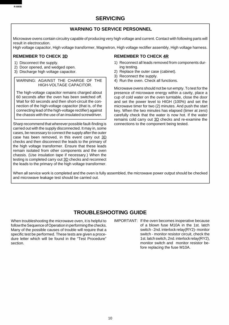
When troubleshooting the microwave oven, it is helpful tofollow the Sequence of Operation in performing the checks.Many of the possible causes of trouble will require that aspecific test be performed. These tests are given a proce-dure letter which will be found in the “Test Procedure”section.
IMPORTANT: If the oven becomes inoperative becauseof a blown fuse M10A in the 1st. latchswitch - 2nd. interlock relay(RY2)- monitorswitch - monitor resistor circuit, check the1st. latch switch, 2nd. interlock relay(RY2),monitor switch and monitor resistor be-fore replacing the fuse M10A.
TROUBLESHOOTING GUIDE
REMEMBER TO CHECK 3D
1) Disconnect the supply.2) Door opened, and wedged open.3) Discharge high voltage capacitor.
WARNING: AGAINST THE CHARGE OF THEHIGH-VOLTAGE CAPACITOR.
The high-voltage capacitor remains charged about60 seconds after the oven has been switched off.Wait for 60 seconds and then short-circuit the con-nection of the high-voltage capacitor (that is, of theconnecting lead of the high-voltage rectifier) againstthe chassis with the use of an insulated screwdriver.
Sharp recommend that wherever possible fault-finding iscarried out with the supply disconnected. It may in, somecases, be necessary to connect the supply after the outercase has been removed, in this event carry out 3Dchecks and then disconnect the leads to the primary ofthe high voltage transformer. Ensure that these leadsremain isolated from other components and the ovenchassis. (Use insulation tape if necessary.) When thetesting is completed carry out 3D checks and reconnectthe leads to the primary of the high voltage transformer.
When all service work is completed and the oven is fully assembled, the microwave power output should be checkedand microwave leakage test should be carried out.
SERVICING
WARNING TO SERVICE PERSONNEL
Microwave ovens contain circuitry capable of producing very high voltage and current. Contact with following parts willresult in electrocution.High voltage capacitor, High voltage transformer, Magnetron, High voltage rectifier assembly, High voltage harness.
REMEMBER TO CHECK 4R1) Reconnect all leads removed from components dur-
ing testing.2) Replace the outer case (cabinet).3) Reconnect the supply.4) Run the oven. Check all functions.
Microwave ovens should not be run empty. To test for thepresence of microwave energy within a cavity, place acup of cold water on the oven turntable, close the doorand set the power level to HIGH (100%) and set themicrowave timer for two (2) minutes. And push the startkey. When the two minutes has elapsed (timer at zero)carefully check that the water is now hot. If the waterremains cold carry out 3D checks and re-examine theconnections to the component being tested.

R-880B
11
Fus
e 15
A b
low
s w
hen
pow
er c
ord
is p
lugg
ed in
to w
all o
utle
t.
Fus
e M
10A
blo
ws
whe
n th
e do
or is
ope
ned.
Hom
e fu
se b
low
s w
hen
pow
er c
ord
is p
lugg
ed in
to w
all o
utle
t.
"SH
AR
P M
ICR
O-
OV
EN
" do
es n
ot a
ppea
r in
dis
play
whe
n po
wer
cor
d is
pl
ugge
d in
to w
all o
utle
t.
Dis
play
doe
s no
t ope
rate
pro
perly
whe
n S
TO
P/C
LEA
R p
ad is
pre
ssed
.
Ove
n do
es n
ot s
tart
whe
n th
e IN
ST
AN
T C
OO
K/
ST
AR
T p
ad i
s pr
esse
d.
(Dis
play
ope
rate
s.)
Ove
n la
mp
does
not
ligh
t. (T
urnt
able
mot
or o
pera
tes.
)
Fan
mot
or d
oes
not o
pera
te. (
Ove
n la
mp
light
s.)
Tur
ntab
le m
otor
doe
s no
t ope
rate
. (O
ven
lam
p lig
hts.
)
Ove
n or
el
ectr
ical
pa
rts
does
no
t st
op
whe
n co
okin
g tim
e is
0
or
ST
OP
/CLE
AR
pad
is p
ress
ed.
Ove
n go
es in
to c
ook
cycl
e bu
t shu
ts d
own
befo
re e
nd o
f coo
king
cyc
le.
Ove
n se
ems
to b
e op
erat
ing
but l
ittle
or
no h
eat i
s pr
oduc
ed in
ove
n lo
ad.
Ove
n do
es
not
oper
atin
g pr
oper
ly
durin
g va
riabl
e co
okin
g co
nditi
on
exce
pt 1
00%
coo
king
con
ditio
n.
Top
hea
ters
do
not o
pera
te.
Bot
tom
hea
ter
does
not
ope
rate
.
Ove
n se
ems
to b
e op
erat
ing
but
little
or
no h
eat
is p
rodu
ced
in o
ven
load
. (M
icro
wav
e po
wer
doe
s no
t see
m to
be
gene
rate
d pr
oper
ly.)
Top
hea
ters
do
not o
pera
te.
Bot
tom
hea
ter
does
not
ope
rate
.
Tem
pera
ture
is lo
wer
or
high
er th
an p
rese
t.
Con
vect
ion
mot
or d
oes
not o
pera
te.
Ove
n st
ops
afte
r 4
min
utes
15
sec.
.
Ove
n is
in
sens
or c
ooki
ng c
ondi
tion
but
AH
sen
sor
does
not
end
1st
. st
age
or d
oes
not s
top
cook
ing
cycl
e or
the
oven
sto
ps s
oon.
CO
ND
ITIO
N P
RO
BLE
M
MAGNETRON
HIGH VOLTAGE TRANSFORMER
H.V. RECTIFIER ASSEMBLY
HIGH VOLTAGE CAPACITOR
1ST. LATCH SWITCH
MONITOR SWITCH
2ND. INTERLOCK RELAY CONTROL SWITCH
THERMAL CUT-OUT 125˚C
THERMAL CUT-OUT 170˚C
FUSE M10A
FUSE 15A
NOISE FILTER
FAN MOTOR
TURNTABLE MOTOR
CONVECTION MOTOR
TOP HEATERS
BOTTOM HEATER
THERMISTOR
TOUCH CONTROL PANEL
KEY UNIT
RELAY RY1
RELAY RY2
RELAY RY3
RELAY RY4
RELAY RY5
RELAY RY6
FOIL PATTERN ON P.W.B.
AH SENSOR
POWER SUPPLY CORD
OVEN LAMP
SHORTED WIRE HARNESS
OPENED WIRE HARNESS
MIS-ADJUSTMENT OF SWITCHES
A
B
C
D
E
E
E
F
F
G
H
IJ
JJ
K
K
L
M
N
O
O
O
O
O
O
P
Q
MIX
C
OO
KIN
G
CO
ND
ITIO
N
CO
NV
EC
TIO
N
CO
OK
ING
C
ON
DIT
ION
AH
. SE
NS
OR
OF
F
CO
ND
ITIO
N
CO
OK
ING
C
ON
DIT
ION
(C
OM
MO
N M
OD
E)
MIC
RO
WA
VE
C
OO
KIN
G
CO
ND
ITIO
N
GR
ILL
C
OO
KIN
G
CO
ND
ITIO
N
PO
SS
IBLE
CA
SE
A
ND
D
EF
EC
TIV
E P
AR
TS

12
R-880B
A MAGNETRON TEST
TEST PROCEDURES
PROCEDURELETTER COMPONENT TEST
CARRY OUT 3D CHECKS.
Isolate the magnetron from high voltage circuit by removing all leads connected to filament terminal.
To test for an open circuit filament use an ohmmeter to make a continuity test between the magnetronfilament terminals, the meter should show a reading of less than 1 ohm.
To test for short filament to anode condition, connect ohmmeter between one of the filament terminalsand the case of the magnetron (ground). This test should be indicated an infinite resistance. If a lowor zero resistance reading is obtained then the magnetron should be replaced.
MICROWAVE OUTPUT POWER (1 litre load)The following test procedure should be carried out with the microwave oven in a fully assembledcondition (outer case fitted). Microwave output power from the magnetron can be measured by wayof IEC 705, i.e. it is measured by how much power the water load can absorb. To measure themicrowave output power in the microwave oven, the relation of calorie and watt is used. When P(W)heating works for t(second), approximately P x t/4.187 calorie is generated. On the other hand, if thetemperature of the water with V(ml) rises ∆T (°C) during this microwave heating period, the calorie ofthe water is V x ∆T.
Measuring condition:1. Container
The water container must be a cylindrical borosilicate glass vessel having a maximum materialthickness of 3 mm and an outside diameter of approximately 190 mm.
2. Temperature of the oven and vesselThe oven and the empty vessel are at ambient temperature prior to the start the test.
3. Temperature of the waterThe initial temperature of the water is (10±2)°C.
4. Select the initial and final water temperature so that the maximum difference between the final watertemperature and the ambient temperature is 5K.
5. Select stirring devices and measuring instruments in order to minimize addition or removal of heat.6. The graduation of the thermometer must be scaled by 0.1°C at minimum and be an accurate
thermometer.7. The water load must be (1000±5) g.8. “t” is measured while the microwave generator is operating at full power. Magnetron filament heat-
up time is not included.
NOTE: The operation time of the microwave oven is “t + 2” sec. (2 sec. is magnetron filament heat-up time.)
Measuring method:1. Measure the initial temperature of the water before the water is added to the vessel.
(Example: The initial temperature T1 = 11°C)2. Add the 1 litre water to the vessel.3. Place the load on the centre of the shelf.4. Operate the microwave oven at HIGH for the temperature of the water rises by a value ∆ T of
(10 ± 2) K.5. Stir the water to equalize temperature throughout the vessel.6. Measure the final water temperature. (Example: The final temperature T2 = 21°C)7. Calculate the microwave power output P in watts from above formula.
NEVER TOUCH ANY PART IN THE CIRCUIT WITH YOUR HAND OR AN INSULATED TOOLWHILE THE OVEN IS IN OPERATION.
The formula is as follows;P x t / 4.187 = V x ∆ T P (W) = 4.187 x V x ∆T / t
Our condition for water load is as follows:Room temperature ........... around 20°C Power supply Voltage .............. Rated voltageWater load.................................. 1000 g Initial temperature .............................. 10±2°CHeating time .............................. 47 sec.P = 90 x ∆T

R-880B
13
Initial temperature .................................................................................................. T1 = 11°CTemperature after (47 + 2) = 49 sec ...................................................................... T2 = 21°CTemperature difference Cold-Warm....................................................................... ∆T1 = 10CMeasured output powerThe equation is “P = 90 x ∆T” ...................................................... P = 90 x 10°C = 900 Watts
JUDGMENT: The measured output power should be at least ± 15 % of the rated output power.
CAUTION: 1°C CORRESPONDS TO 90 WATTS. REPEAT MEASUREMENT IF THE POWER ISINSUFFICIENT.
TEST PROCEDURES
PROCEDURELETTER COMPONENT TEST
1000g
1000g1000g
T1˚C T2˚CHeat up for 49 sec
B HIGH VOLTAGE TRANSFORMER TEST
WARNING: High voltage and large currents are present at the secondary winding andfilament winding of the high voltage transformer. It is very dangerous to worknear this part when the oven is on. NEVER make any voltage measurementsof the high-voltage circuits, including the magnetron filament.
C HIGH VOLTAGE RECTIFIER ASSEMBLY TEST
HIGH VOLTAGE RECTIFIER TEST
CARRY OUT 3D CHECKS.Isolate the high voltage rectifier assembly from the HV circuit. The high voltage rectifier can be testedusing an ohmmeter set to its highest range. Connect the ohmmeter across the terminal B+C of the highvoltage rectifier and note the reading obtained. Reverse the meter leads and note this second reading.The normal resistance is infinite in one direction and more than 100 kΩ in the other direction.CARRY OUT 4R CHECKS.
ASYMMETRIC RECTIFIER TEST
CARRY OUT 3D CHECKS.
Isolate the high voltage rectifier assembly from the HV circuit. The asymmetric can be tested using anohmmeter set to its highest range across the terminals A+B of the asymmetric rectifier and note thereading obtained. Reverse the meter leads and note this second reading. If an open circuit is indicatedin both direction then the asymmetric rectifier is good. If an asymmetric rectifier is shorted in eitherdirection, then the asymmetric rectifier is probably faulty and must be replaced with high voltagerectifier. When the asymmetric rectifier is defective, check whether magnetron, high voltage rectifier,high voltage wire or filament winding of the high voltage transformer is shorted.
CARRY OUT 4R CHECKS.
CARRY OUT 3D CHECKS.Disconnect the leads to the primary winding of the high voltage transformer. Disconnect the filamentand secondary winding connections from the rest of the HV circuitry. Using an ohmmeter, set on a lowrange, it is possible to check the continuity of all three windings. The following readings should beobtained:-
a. Primary winding ................................ approximately 1.5 Ωb. Secondary winding .......................... approximately 117 Ωc. Filament winding......................................... less than 1 Ω
If the readings obtained are not stated as above, then the high voltage transformer is probably faultyand should be replaced.CARRY OUT 4R CHECKS.
A B
C
D2 D1
ASYMMETRIC RECTIFIER
HIGH VOLTAGE RECTIFIER

14
R-880B
TEST PROCEDURES
PROCEDURELETTER COMPONENT TEST
E SWITCH TEST
CARRY OUT 3D CHECKS.Isolate the switch to be tested and using an ohmmeter check between the terminals as described inthe following table.
Table: Terminal Connection of SwitchPlunger Operation COM to NO COM to NCReleased Open circuit Short circuitDepressed Short circuit Open circuit
COM; Common terminal,NO; Normally open terminalNC; Normally close terminal
If incorrect readings are obtained, make the necessary switch adjustment or replace the switch.
CARRY OUT 4R CHECKS.
F THERMAL CUT-OUT TEST
CARRY OUT 3D CHECKS.
Disconnect the leads from the terminals of the thermal cut-out. Then using an ohmmeter, make a continuitytest across the two terminals as described in the below.
Table: Thermal Cut-out TestTemperature of "ON" Temperature of "OFF" Indication of ohmmeter
Parts Name condition (closed circuit). condition (open circuit). (When room temperature(˚C) (˚C) is approx. 20˚C.)
Thermal cut-out 125˚C This is not resetable type. Above 125˚C Closed circuit
Thermal cut-out 170˚C Cuts back in at 155˚C. Above 170˚C Closed circuit
If incorrect readings are obtained, replace the thermal cut-out.
An open circuit thermal cut-out (MG) indicates that the magnetron has overheated, this may be dueto resistricted ventilation, cooling fan failure or a fault condition within the magnetron or HV. circuit.
An open circuit thermal cut-out (OVEN) indicates that the food in the oven cavity may catch fire, thismay be due to over heating produced by improper setting of the cooking timer or failure of the controlpanel.
CARRY OUT 4R CHECKS.
D HIGH VOLTAGE CAPACITOR TEST
CARRY OUT 3D CHECKS.
A. Isolate the high voltage capacitor from the circuit.B. Continuity check must be carried out with measuring instrument which is set to the highest
resistance range.C. A normal capacitor shows continuity for a short time (kick) and then a resistance of about 10MΩ after
it has been charged.D. A short-circuited capacitor shows continuity all the time.E. An open capacitor constantly shows a resistance about 10 MΩ because of its internal 10MΩ
resistance.F. When the internal wire is opened in the high voltage capacitor shows an infinite resistance.G. The resistance across all the terminals and the chassis must be infinite when the capacitor is
normal.If incorrect reading are obtained, the high voltage capacitor must be replaced.
CARRY OUT 4R CHECKS.
NOTE: FOR MEASUREMENT OF THE RESISTANCE OF THE RECTIFIER, THE BATTERIES OFTHE MEASURING INSTRUMENT MUST HAVE A VOLTAGE AT LEAST 6 VOLTS, BE-CAUSE OTHERWISE AN INFINITE RESISTANCE MIGHT BE SHOWN IN BOTH DIREC-TIONS.

R-880B
15
CARRY OUT 3D CHECKS.
Disconnect the leads from the motor. Using an ohmmeter, check the resistance between the twoterminals as described in the table below.
Table: Resistance of MotorMotors Resistance
Fan motor Approximately 290 ΩTurntable motor Approximately 14 kΩConvection motor Approximately 293 Ω
If incorrect readings are obtained, replace the motor.
CARRY OUT 4R CHECKS.
TEST PROCEDURES
PROCEDURELETTER COMPONENT TEST
H BLOWN FUSE 15A
J MOTOR WINDING TEST
CARRY OUT 3D CHECKS.
Disconnect the leads from the terminals of noise filter.Using an ohmmeter, check between the terminals asdescribed in the following table.
MEASURING POINTS INDICATION OF OHMMETERBetween N and L Approx. 680 kΩBetween terminal N and WHITE Short circuitBetween terminal L and RED Short circuit
If incorrect readings are absorbed, replace the noise filter unit.
CARRY OUT 4R CHECKS.
I NOISE FILTER TEST
F8A
WHT
RED
N
L
G BLOWN FUSE M10A
CARRY OUT 3D CHECKS.If the fuse M10A is blown when the door is opened, check the 1st. latch switch, 2nd. interlock relay,monitor switch and monitor resistor.
If the fuse M10A is blown, there could be a short or ground in electrical parts or wire harness. Checkthem and replace the defective parts or repair the wire harness.If the fuse M10A is blown, there could be a short in the asymmetric rectifier or there is a ground in wireharness. A short in the asymmetric rectifier may be occurred due to short or ground in H.V. rectifier,magnetron, high voltage transformer or H.V. wire. Check them and replace the defective parts or repairthe wire harness.
CARRY OUT 4R CHECKS.
CAUTION: Only replace fuse M10A with the correct value replacement.
CARRY OUT 3D CHECKS.
If the fuse 15A is blown, there could be a short or ground in electrical parts or wire harness. Check themand replace the defective parts or repair the wire harness.
CARRY OUT 4R CHECKS.
CAUTION: Only replace fuse 15A with the correct value replacement.
K TOP HEATERS AND BOTTOM HEATER TEST
CARRY OUT 3D CHECKS.
Before carrying out the following tests make sure the heater is cool completely.
1. Resistance of heater.Disconnect the wire leads to the heater to be tested. Using ohmmeter with low resistance range.

16
R-880B
TEST PROCEDURES
PROCEDURELETTER COMPONENT TEST
Check the resistance across the terminals of the heater as described in the following table.Table: Resistance of heater
Parts name ResistanceTop heaters Approximately 20 Ω x 2 = 40 ΩBottom heater Approximately 61 Ω
2. Insulation resistance.Disconnect the wire leads to the heater to be tested. Check the insulation resistance between theheater terminal and cavity using a 500V - 100MΩ insulation tester. The insulation resistance shouldbe more than 10 MΩ in the cold start.
If the results of above test 1 and/or 2 are out of above specifications, the heater is probably faulty andshould be replaced.
CARRY OUT 4R CHECKS.
L THERMISTOR TEST
1. CARRY OUT 3D CHECKS.2. Disconnect connector-D from the control unit. Measure the resistance of the thermistor with an
ohmmeter. Connect the ohmmeter leads to Pin No’s D1 and D3.
Room Temperature Resistance68˚F(20˚C) - 86˚F(30˚C) Approx. 293kΩ - 184KΩ
3. If the meter does not indicate above resistance, replace the thermistor4. CARRY OUT 4R CHECKS.
The touch control panel consists of circuits including semiconductors such as LSI, ICs, etc. Therefore,unlike conventional microwave ovens, proper maintenance can not be performed with only a voltmeterand ohmmeter.In this service manual, the touch control panel assembly is divided into two units, Control Unit and KeyUnit, and also the Control unit is divided into two units, CPU unit and Power unit, and troubleshootingby replacement is described according to the symptoms indicated.1. Key Unit Note : Check key unit ribbon connection before replacement.
The following symptoms indicate a defective key unit. Replace the key unit.a) When touching the pads, a certain pad produces no signal at all.b) When touching a number pad, two figures or more are displayed.c) When touching the pads, sometimes a pad produces no signal.
2. Control PanelThe following symptoms indicate a defective control unit. Before replacing the control unit.perform the key unit test (Procedure N) to determine if control unit is faulty.
2-1 In connection with padsa) When touching the pads, a certain group of pads do not produce a signal.b) When touching the pads, no pads produce a signal.
2-2 In connection with indicatorsa) At a certain digit, all or some segments do not light up.b) At a certain digit, brightness is low.c) Only one indicator does not light up.d) The corresponding segments of all digits do not light up; or they continue to light up.e) Wrong figure appears.f) A certain group of indicators do not light up.g) The figure of all digits flicker.
2-3 Other possible troubles caused by defective control unit.a) Buzzer does not sound or continues to sound.b) Clock does not operate properly.c) Cooking is not possible.d) Proper temperature measurement is not obtained.
M CONTROL PANEL ASSEMBLY TEST

R-880B
17
TEST PROCEDURES
PROCEDURELETTER COMPONENT TEST
If the display fails to clear when the STOP/CLEAR pad is depressed, first verify the flat ribbon cableis marking good contact, verify that the door sensing switch (stop switch) operates properly; that is thecontacts are closed when the door is closed and open when the door is open. If the door sensing switch(stop switch) is good, disconnect the flat ribbon cable that connects the key unit to the control unit andmake sure the door sensing switch is closed (either close the door or short the door sensing switchconnecter). Use the Key unit matrix indicated on the control panel schematic and place a jumper wirebetween the pins that correspond to the STOP/CLEAR pad marking momentary contact. If the controlunit responds by clearing with a beep the key unit is faulty and must be replaced. If the control unit doesnot respond, it is a faulty and must be replaced. If a specific pad does not respond, the above methodmay be used (after clearing the control unit) to determine if the control unit or key pad is at fault.
N KEY UNIT TEST
CARRY OUT 3D CHECKS.
Remove the outer case and check voltage between Pin No. 1 of the 3 pin connector (A) and thecommon terminal of the relay RY6 on the control unit with an A.C. voltmeter.The meter should indicate 220 volts, if not check oven circuit.
Relay TestCheck voltage at the relay coil with a D.C. voltmeter during the microwave cooking operation, grilloperation, convection operation or mix operation.
DC. voltage indicated .......... Defective relay.DC. voltage not indicated .... Check diode which is connected to the relay coil. If diode is good,
control unit is defective.
RELAY SYMBOL OPERATIONAL VOLTAGE CONNECTED COMPONENTS
RY1 Approx. 24.0V D.C. Convection motor
RY2 Approx. 24.0V D.C. High voltage transformer
RY3 Approx. 24.0V D.C. Grill heaters (Top)
RY4 Approx. 24.0V D.C. Bottom heater
RY5 Approx. 24.0V D.C. Fan motor
RY6 Approx. 24.0V D.C. Oven lamp / Turntable motor
CARRY OUT 4R CHECKS.
O RELAY TEST
CARRY OUT 4R CHECKS.
P PROCEDURES TO BE TAKEN WHEN THE FOIL PATTERN ON THE PRINTED WIRING BOARD(PWB) IS OPEN
To protect the electronic circuits, this model is provided with a fine foil pattern added to the input circuiton the PWB, this foil pattern acts as a fuse. If the foil pattern is open, follow the troubleshooting guidegiven below for repair.Problem: POWER ON, indicator does not light up.
CARRY OUT 3D CHECKS.
5 4 3 2 1
0 9 8 7 6
G 8 G 7 G 6 G 5 G 4 G 3 G 2 G 1
G12
G11
G10
G 9 HELP
MOREPasta
160˚C 150˚C 130˚C 70˚C 40˚C
250˚C 230˚C 220˚C 200˚C 180˚C
Rice
EASY DEFROST
PREHEAT
Fresh Vegetables
Frozen Vegetables
CONVENIENCE /PIZZA
INSTANT COOK
START
REHEAT SENSOR
CONVEC
Jacket Potato
Reheat Pie
POWER LEVEL
GRILLCLOCK MIX
STOP CLEAR
MULTI COOK
LESS

18
R-880B
STEPS OCCURRENCE CAUSE OR CORRECTION
1 The rated AC voltage is not present at Check supply voltage and oven power cord.Power terminal of CPU connector (CN-A).
2 The rated AC voltage is present at primary Low voltage transformer or secondary circuit defective.side of low voltage transformer. Check and repair.
3 Only pattern at "a" is broken. *Insert jumper wire J1 and solder.(CARRY OUT 3D CHECKS BEFORE REPAIR.)
4 Pattern at "a" and "b" are broken. *Insert the coil RCILF2003YAZZ between "c" and "d".(CARRY OUT 3D CHECKS BEFORE REPAIR.)
NOTE: *At the time of these repairs, make avisual inspection of the varistor forburning damage and examine thetransformer with tester for the pres-ence of layer short circuit (check pri-mary coil resistance).If any abnormal condition is detected,replace the defective parts.
CARRY OUT 4R CHECKS.
TEST PROCEDURES
PROCEDURELETTER COMPONENT TEST
Checking the initial sensor cooking condition(1) The oven should be plugged in at least two minutes before sensor cooking.(2) Room temperature should not exceed 35˚C.(3) The unit should not be installed in any area where heat and steam are generated. The unit should
not be installed, for example, next to a conventional surface unit. Refer to the "INSTALLATIONInstructions" .
(4) Exhaust vents are provided on the back of the unit for proper cooling and air flow in the cavity. Topermit adequate ventilation, be sure to install so as not to block these vents. There should be somespace for air circulation.
(5) Be sure the exterior of the cooking container and the interior of the oven are dry. Wipe off anymoisture with a dry cloth or paper towel.
(6) The Sensor works with food at normal storage temperature. For example, chicken pieces wouldbe at refrigerator temperature and canned soup at room temperature.
(7) Avoid using aerosol sprays or cleaning solvents near the oven while using Sensor settings. Thesensor will detect the vapor given of by the spray and turn off before food is properly cooked.
(8) After the oven is started on sensor cooking condition, if the sensor has not detected the vapor ofthe food, ERROR will appear and the oven will shut off.
Water load cooking testMake sure the oven has been plugged in at least five minutes before checking sensor cook operation.The cabinet should be installed and screws tightened.(1) Fill approximately 200 milliliters (7.2 oz) of tap water in a 1000 milliliter measuring cup.(2) Place the container on the center of tray in the oven cavity.(3) Close the door.(4) Touch Fresh vegetables pad. Now, the oven is in the sensor cooking condition and "FRESH",
"VEGETABLES", "SENSOR" and "COOKING" will appear in the display.(5) The oven will operate for the first 16 seconds, without generating microwave energy.
When the AH sensor is defective (open or short), ERROR will appear in the display immediately.If ERROR appears check sensor wire connections and/or AH sensor.NOTE: ERROR will appear if the door is opened or STOP/CLEAR pad is touched during first stage of
sensor cooking.(6) After approximately 16 seconds, microwave energy is produced, and the display should start to
count down the remaining cooking time and oven should turn off after water is boiling (bubbling).If the oven does not turn off, replace the AH sensor or check the control unit, refer to explanationbelow.
Q AH SENSOR TEST
CN - A
AC
a
b d
c VRS1
1
FAN
(J1
)
5
R-880B
19
TEST PROCEDURES
PROCEDURELETTER COMPONENT TEST
TESTING METHOD FOR AH SENSOR AND/OR CONTROL UNITTo determine if the sensor is defective, the simplest method is to replace it with a new replacementsensor.(1) Disconnect oven from power supply and then remove outer case.(2) Discharge the high voltage capacitor.(3) Remove the AH sensor.(4) Install the new AH sensor.(5) Re-install the outer case.(6) Reconnect the oven to the power supply and check the sensor cook operation, proceed as follows:
6-1. Fill approximately 200 milliliters (7.2 oz) of tap water in a 1000 milliliter measuring cup.6-2. Place the container on the center of tray in the oven cavity.6-3. Close the door.6-4. Touch Fresh Vegetables pad.6-5. The control panel is in automatic Sensor operation.6-6. The display will start to count down the remaining cooking time, and the oven will turn off
automatically after the water is boiling (babbling).If new sensor dose not operate properly, the problem is with the control unit.
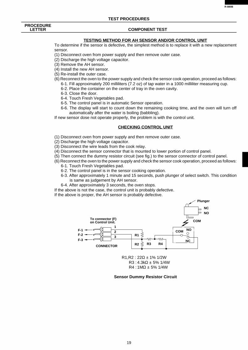
CHECKING CONTROL UNIT
(1) Disconnect oven from power supply and then remove outer case.(2) Discharge the high voltage capacitor.(3) Disconnect the wire leads from the cook relay.(4) Disconnect the sensor connector that is mounted to lower portion of control panel.(5) Then connect the dummy resistor circuit (see fig.) to the sensor connector of control panel.(6) Reconnect the oven to the power supply and check the sensor cook operation, proceed as follows:
6-1. Touch Fresh Vegetables pad.6-2. The control panel is in the sensor cooking operation.6-3. After approximately 1 minute and 15 seconds, push plunger of select switch. This condition
is same as judgement by AH sensor.6-4. After approximately 3 seconds, the oven stops.
If the above is not the case, the control unit is probably defective.If the above is proper, the AH sensor is probably defective.
R1,R2 : 22Ω ± 1% 1/2WR3 : 4.3kΩ ± 5% 1/4WR4 : 1MΩ ± 5% 1/4W
Sensor Dummy Resistor Circuit
Plunger
NC
NO
COM
COM NO
NCR3 R4
R1
R2
1
2
3
F-1F-2
F-3
To connector (F) on Control Unit.
CONNECTOR

20
R-880B
DESCRIPTION OF LSI
LSI(IZA927DR)The I/O signal of the LSI(IZA927DR) are detailed in the following table.
Pin No. Signal I/O Description
TOUCH CONTROL PANEL ASSEMBLY
OUTLINE OF TOUCH CONTROL PANEL
4) ACLA circuit to generate a signal which resets the LSI to theinitial state when power is supplied.
5) Buzzer CircuitThe buzzer is responsive to signals from the LSI to emitaudible sounds (key touch sound and completionsound).
6) Door Sensing Switch (Stop Switch)A switch to "tell" the LSI if the door is open or closed.
7) Relay CircuitTo drive the magnetron, grill heaters, bottom heater,convection motor, fan motor, turntable motor, convec-tion motor and light the oven lamp.
8) Back Light CircuitA circuit to drive the back light (Light emitting diodesLD1 - LD10).
9) Indicator CircuitThis circuit consists of 2 line, 7-digits, 45-segmentsand 5-common electrodes using a Liquid Crystal Dis-play.
10) Temperature Measurement Circuit : (OVEN THER-MISTOR)The temperature in the oven cavity is sensed by thethermistor. The variation of resistance according tosensed temperature is detected by the temperaturemeasurement circuit and the result applied to LSI. TheLSI uses this information to control the relay anddisplay units.
11) Absolute Humidity Sensor CircuitThis circuit detects the humidity of a food which isbeing cooked, to control its automatic cooking.
The touch control section consists of the following units asshown in the touch control panel circuit.
(1) Key Unit(2) Control Unit (The Control unit consists of Power unit
and CPU unit.)
The principal functions of these units and signals commu-nicated among them are explained below.
Key UnitThe key unit is composed of a matrix, signals generated inthe LSI are sent to the key unit from P40, P41, P72, P73P74, P75, P76 and P77.When a key pad is touched, a signal is completed throughthe key unit and passed back to the LSI through P44 - P47to perform the function that was requested.
Control UnitControl unit consists of LSI, power source circuit, synchro-nizing signal circuit, ACL circuit, buzzer circuit, relaycircuit, temperature measurement circuit, indicator circuit,absolute humidity sensor circuit and back light circuit.
1) LSIThis LSI controls the temperature measurement sig-nal, AH sensor signal, key strobe signal, relay drivingsignal for oven function and indicator signal.
2) Power Source CircuitThis circuit generates voltage necessary in the controlunit.
Symbol Voltage Application
VC -5.2V LSI(IC1)
3) Synchronizing Signal CircuitThe power source synchronizing signal is available inorder to compose a basic standard time in the clockcircuit. It accompanies a very small error because itworks on commercial frequency.
1 C1 IN Terminal not used.
2 VL1 IN Power source voltage input terminal.Standard voltage for LCD.
3-5 AN7-AN5 IN Heating constant compensation terminal.
6 AN4 IN Terminal not used.
7 AN3 IN Temperature measurement input: OVEN THERMISTOR.By inputting DC voltage corresponding to the temperature detected by thethermistor, this input is converted into temperature by the A/D converter built intothe LSI.

R-880B
21
8 AN2 IN Input signal which communicates the door open/close information to LSI.
Door closed; "H" level signal.Door opened; "L" level signal.
9 AN1 IN AH sensor input.This input is an analog input terminal from the AH sensor circuit, and connectedto the A/D converter built into the LSI.
10 AN0 IN Used for initial balancing of the bridge circuit (absolute humidity sensor). Thisinput is an analog input terminal from the AH sensor circuit, and connected tothe A/D converter built into LSI.This input is an analog input terminal from the AH sensor circuit, and connectedto the A/D converter built into the LSI.
11 P57 OUT Timing signal output terminal for temperature measurement(OVENTHERMISTOR)."H" level (GND) : Thermistor OPEN timing."L" level (-5V) : Temperature measuring timing. (Convection cooking)
12 P56 OUT Signal to sound buzzer.A: key touch sound.B: Completion sound.C: When the temperature of the oven
cavity reaches the presettemperature in the preheating mode,or when the preheating hold time (30minutes) is elapsed.
13 P55 OUT Timing signal output terminal for temperature measurement(OVENTHERMISTOR)."H" level (GND) : Thermistor OPEN timing."L" level (-5V) : Temperature measuring timing. (Convection cooking)
14-18 P54-P50 OUT Used for initial balancing of the bridge circuit (absolute humidity sensor).
19 P47 IN Signal coming from touch key.When any one of G12 line keys on key matrix is touched, a corresponding signalfrom P40, P41, P72, P73, P74, P75, P76 and P77 will be input into P47. When nokey is touched, the signal is held at "L" level.
20 P46 IN Signal similar to P47.When any one of G11 line keys on key matrix is touched, a corresponding signalwill be input into P46.
21 P45 IN Signal similar to P47.When any one of G10 line keys on key matrix is touched, a corresponding signalwill be input into P45.
22 P44 IN Signal similar to P47.When any one of G9 line keys on key matrix is touched, a corresponding signal willbe input into P44.
23 INT1 IN Terminal not used.
24 INT0 IN Signal to synchronized LSI with commercial power sourcefrequency(50Hz).This is basic timing for time processing of LSI.
25 P41 OUT Key strobe signal.Signal applied to touch-key section. A pulse signal is input to P44 - P47 terminalwhile one of G8 line key on matrix is touched.
26 P40 OUT Key strobe signal.Signal applied to touch-key section. A pulse signal is input to P44 - P47 terminalwhile one of G7 line key on matrix is touched.
27 P77 OUT Key strobe signal.Signal applied to touch-key section. A pulse signal is input to P44 - P47 terminalwhile one of G6 line key on matrix is touched.
28 P76 OUT Key strobe signal.Signal applied to touch-key section. A pulse signal is input to P44 - P47 terminalwhile one of G5 line key on matrix is touched.
Pin No. Signal I/O Description
20 msec.
H : GND
L (-5V)
A
B
CH: GND
L
0.12 sec
2.4 sec
1.2 sec 1.2 sec

22
R-880B
29 P75 OUT Key strobe signal.Signal applied to touch-key section. A pulse signal is input to P44 - P47 terminalwhile one of G4 line key on matrix is touched.
30 P74 OUT Key strobe signal.Signal applied to touch-key section. A pulse signal is input to P44 - P47 terminalwhile one of G3 line key on matrix is touched.
31 P73 OUT Key strobe signal.Signal applied to touch-key section. A pulse signal is input to P44 - P47 terminalwhile one of G2 line key on matrix is touched.
32 P72 OUT Key strobe signal.Signal applied to touch-key section. A pulse signal is input to P44 - P47 terminalwhile one of G1 line key on matrix is touched.
33 P71 OUT Oven lamp and turntable motor driving signal(Square Waveform : 50Hz).
To turn on and off shut-off relay(RY6). The square waveform voltageis delivered to the relay (RY6) drivingcircuit.
34 P70 IN Connected to VC.
35 RESET IN Auto clear terminal.Signal is input to reset the LSI to the initial state when power is applied. Temporarilyset to "L" level the moment power is applied, at this time the LSI is reset. Thereafterset at "H" level.
36 P81 OUT Magnetron high-voltage circuit driving signal.
To turn on and off the cookrelay (RY2). In 100%operation, the signals hold "L"level during microwavecooking and "H" level while notcooking. In other cookingmodes (70%, 50%, 30%,10%) the signal turns to "H"level and "L" level in repetitionaccording to the power level.
37 P80 OUT Grill heaters (TOP HEATER) driving signal.
To turn on and off the grill heatersrelay (RY3). "L" level during grill(TOP GRILL, TOP ANDBOTTOM) cooking, Convectioncooking or Mix top grill cooking,"H" level otherwise.The heater relay turns on and offwithin a 48 second time base inaccordance with the specialprogram in LSI.
38 XIN IN Internal clock oscillation frequency input setting.The internal clock frequency is set by inserting the ceramic filter oscillation circuitwith respect to XIN terminal.
39 XOUT OUT Internal clock oscillation frequency control output.Output to control oscillation input of XOUT.
40 VSS IN Power source voltage: -5V.VC voltage of power source circuit input.
41 P27 OUT Bottom heater driving signal.To turn on and off the bottom relay(RY4). "L" level during grill (TOP ANDBOTTOM) cooking, Convectioncooking or Mix bottom cooking, "H"level otherwise.The heater relay turns on and offwithin a 48 second time base inaccordance with the special programin LSI.
Pin No. Signal I/O Description
Power output ON time OFF time100 % 48 sec. 0 sec.
90 % 44 sec. 4 sec.80 % 40 sec. 8 sec.70 % 36 sec. 12 sec.60 % 32 sec. 16 sec.50 % 26 sec. 22 sec.40 % 22 sec. 26 sec.30 % 16 sec. 32 sec.20 % 12 sec. 36 sec.10 % 8 sec. 40 sec.
ON/OFF time ratio in Mi-cro cooking(a. 32second time base)
ON/OFF time ratio in Mi-cro cooking(a. 48second time base)
MICRO ON OFFCOOK100% 32 sec. 0 sec.
70% 24 sec. 8 sec.50% 18 sec. 14 sec.30% 12 sec. 20 sec.10% 6 sec. 26 sec.
MICRO ON OFFCOOK100% 48 sec. 0 sec.
70% 36 sec. 12 sec.50% 26 sec. 22 sec.30% 16 sec. 32 sec.10% 8 sec. 40 sec.
During cooking
L
H
20 msec.
Power output ON time OFF time100 % 48 sec. 0 sec.
90 % 44 sec. 4 sec.80 % 40 sec. 8 sec.70 % 36 sec. 12 sec.60 % 32 sec. 16 sec.50 % 26 sec. 22 sec.40 % 22 sec. 26 sec.30 % 16 sec. 32 sec.20 % 12 sec. 36 sec.10 % 8 sec. 40 sec.

R-880B
23
42 P26 OUT Convection motor driving signal.To turn on and off shut-off relay(RY1)."L" level during CONVECTION; "H" levelotherwise. (Relay RY1 does not turn onat preheating mode.)
43 P25 OUT Fan motor driving signal.To turn on and off the fan motor relayRY5. "L" level during cooking, or for 5minutes after grill cooking or Mix cookingfor a while after convection. "H" levelotherwise.
44 P24 OUT Terminal not used.
45 P23 OUT Common data signal: COM5.Connected to LCD (Pin No. 37)
46-48 P22-P20 OUT Segment data signal.Connected to LCD. No connection in LCD.
49-50 P17-P16 OUT Segment data signal.Connected to LCD. No connection in LCD.
51-80 SEG39-SEG10 OUT Segment data signal.Connected to LCD.The relation between signals are as follows:
LSI signal (Pin No.) LCD (Pin No.) LSI signal (Pin No.) LCD (Pin No.)SEG 0 (90) ....................SEG45 (51) SEG23 (67) .................SEG17 (17)SEG 1 (89) ....................SEG44 (50) SEG24 (66) .................SEG16 (16)SEG 2 (88) ....................SEG43 (49) SEG25 (65) .................SEG15 (15)SEG 3 (87) ....................SEG42 (48) SEG25 (65) .................SEG15 (32)SEG 4 (86) ....................SEG41 (47) SEG26 (64) .................SEG14 (14)SEG 5 (85) ....................SEG40 (46) SEG27 (63) .................SEG13 (13)SEG 6 (84) ....................SEG39 (45) SEG28 (62) .................SEG12 (12)SEG 7 (83) ....................SEG38 (44) SEG29 (61) .................SEG11 (11)SEG 8 (82) ....................SEG37 (43) SEG30 (60) .................SEG10 (10)SEG 9 (81) ....................SEG31 (31) SEG31 (59) ...................SEG 9 ( 9)SEG10 (80) ...................SEG30 (30) SEG32 (58) ...................SEG 8 ( 8)SEG11 (79) ...................SEG29 (29) SEG33 (57) ...................SEG 7 ( 7)SEG12 (78) ...................SEG28 (28) SEG34 (56) ...................SEG 6 ( 6)SEG13 (77) ...................SEG27 (27) SEG35 (55) ...................SEG 5 ( 5)SEG14 (76) ...................SEG26 (26) SEG36 (54) ...................SEG 4 ( 4)SEG15 (75) ...................SEG25 (25) SEG37 (53) ...................SEG 3 ( 3)SEG16 (74) ...................SEG24 (24) SEG38 (52) ...................SEG 2 ( 2)SEG17 (73) ...................SEG23 (23) SEG39 (51) ...................SEG 1 ( 1)SEG18 (72) ...................SEG22 (22) P16 (50) ......................SEG32 (38)SEG19 (71) ...................SEG21 (21) P17 (49) ......................SEG33 (39)SEG20 (70) ...................SEG20 (20) P20 (48) ......................SEG34 (40)SEG21 (69) ...................SEG19 (19) P21 (47) ......................SEG35 (41)SEG22 (68) ...................SEG18 (18) P22 (46) ......................SEG36 (42)
81 SEG9 OUT Segment data signal.Connected to LCD. No connection in LCD.
82-90 SEG8-SEG0 OUT Segment data signal.Connected to LCD. Signal is similar to SEG39.
91 VCC IN Connected to GND.
92 VREF IN Connected to GND.
93 AVSS IN Connected to VC.
94 COM3 OUT Common data signal: COM4.Connected to LCD (Pin No. 36).
95 COM2 OUT Common data signal: COM3.Connected to LCD (Pin No. 35).
96 COM1 OUT Common data signal: COM2.Connected to LCD (Pin No. 34).
97 COM0 OUT Common data signal: COM1.Connected to LCD (Pin No. 33).
Pin No. Signal I/O Description
ON
OFFDuringcooking
L
GNDH.
(Convection)
ON
OFF
During cooking or for 5 minutes after grill, mix or for awhile after convection.
L
GNDH.

24
R-880B
(1) Structure of Absolute Humidity SensorThe absolute humidity sensor includes two thermistorsas shown in the illustration. One thermistor is housedin the closed vessel filled with dry air while another inthe open vessel. Each sensor is provided with theprotective cover made of metal mesh to be protectedfrom the external airflow.
(2) Operational Principle of Absolute Humidity SensorThe figure below shows the basic structure of anabsolute humidity sensor. A bridge circuit is formed bytwo thermistors and two resistors (R1 and R2).The output of the bridge circuit is to be amplified by theoperational amplifier.Each thermistor is supplied with a current to keep itheated at about 150˚C (302˚F), the resultant heat isdissipated in the air and if the two thermistors areplaced in different humidity conditions they show differ-ent degrees of heat conductivity leading to a potentialdifference between them causing an output voltagefrom the bridge circuit, the intensity of which is in-creased as the absolute humidity of the air increases.Since the output is very minute, it is amplified by theoperational amplifier.
(3) Detector Circuit of Absolute Humidity Sensor Cir-cuitThis detector circuit is used to detect the output voltageof the absolute humidity circuit to allow the LSI tocontrol sensor cooking of the unit. When the unit is setin the sensor cooking mode, 16 seconds clearing cycleoccurs than the detector circuit starts to function andthe LSI observes the initial voltage available at its AN1terminal.
Pin No. Signal I/O Description
98-99 VL3-VL2 IN Power source voltage input terminal.Standard voltage for LCD.
100 C2 IN Terminal not used.
ABSOLUTE HUMIDITY SENSOR CIRCUIT
With this voltage given, the switches SW1 to SW5 inthe LSI are turned on in such a way as to change theresistance values in parallel with R107 ~ R111 of IC2.Changing the resistance values results in that there isthe same potential at both F-3 terminal of the absolutehumidity sensor and AN0 terminal of the LSI. Thevoltage of AN1 terminal will indicate about -2.5V. Thisinitial balancing is set up about 16 seconds after theunit is put in the Sensor Cooking mode. As the sensorcooking proceeds, the food is heated to generatemoisture by which the resistance balance of the bridgecircuit is deviated to increase the voltage available atAN1 terminal of the LSI.Then the LSI observes that voltage at AN1 terminal andcompares it with its initial value, and when the compari-son rate reaches the preset value (fixed for each menuto be cooked), the LSI causes the unit to stop sensorcooking; thereafter, the unit goes in the next operationautomatically.When the LSI starts to detect the initial voltage at AN1terminal 16 seconds after the unit has been put in theSensor Cooking mode, if it is not possible to balance,of the bridge circuit due to disconnection of the abso-lute humidity sensor, ERROR will appear on the dis-play and the cooking is stopped.
1) Absolute humidity sensor circuit
Sensing part (Open vessel)
Sensing part (Closed vessel)
Thermistorsventilation opening for sensing
C
S
R3
R1
R2
+
Operational amplifier
Output voltage
S : Thermistor open vesselC : Thermistor closed vessel
2Absolute humidity (g/m )
Out
put v
olta
ge
Absolute humidity vs, output voltage characterist
SW1
SW2
SW3
SW4
SW5
P54
P53
P52
P51
P50
LSI (IC1)
AN0
AN1
620k
300k
150k
75k
37.4k
14
9
17
18
10
16
15
47k
47k
IC210k
0.01
uF
0.01
5uF
0.01
uF
+
VA : -15V VA : -15V
R90
C101
C102
C103
C104
S
F-2 1.8k
F-1
F-3C
3.57k
3.32k
VC : -5V
0.1
uF
C. Thermistor in closed vessel S. Thermistor in open vessel
R107
R108
R112
R105
360kR102R101
R103 R104
D101
R109
R110
R111
R106

R-880B
25
1. Precautions for Handling Electronic ComponentsThis unit uses CMOS LSI in the integral part of the circuits.When handling these parts, the following precautionsshould be strictly followed. CMOS LSI have extremelyhigh impedance at its input and output terminals. For thisreason, it is easily influenced by the surrounding highvoltage power source, static electricity charge in clothes,etc., and sometimes it is not fully protected by the built-inprotection circuit.In order to protect CMOS LSI.1) When storing and transporting, thoroughly wrap them
in aluminium foil. Also wrap PW boards containingthem in aluminium foil.
2) When soldering, ground the technician as shown inthe figure and use grounded soldering iron and worktable.
approx. 1M ohm
2. Shapes of Electronic Components
3. Servicing of Touch Control PanelWe describe the procedures to permit servicing of thetouch control panel of the microwave oven and the pre-cautions you must take when doing so.To perform the servicing, power to the touch control panelis available either from the power line of the oven itself orfrom an external power source.
(1) Servicing the touch control panel with powersupply of the oven :CAUTION:THE HIGH VOLTAGE TRANSFORMER OF THEMICROWAVE OVEN IS STILL LIVE DURINGSERVICING AND PRESENTS A HAZARD .
Therefore, before checking the performance of the touchcontrol panel,1) Disconnect the power supply cord, and then remove
outer case.2) Open the door and block it open.3) Discharge high voltage capacitor.4) Disconnect the leads to the primary of the power
transformer.5) Ensure that these leads remain isolated from other
components and oven chassis by using insulationtape.
6) After that procedure, re-connect the power supply cord.After checking the performance of the touch control panel,1) Disconnect the power supply cord.2) Open the door and block it open.3) Re-connect the leads to the primary of the power
transformer.4) Re-install the outer case (cabinet).
SERVICING
5) Re-connect the power supply cord after the outer caseis installed.
6) Run the oven and check all functions.
A. On some models, the power supply cord between thetouch control panel and the oven itself is so short thatthe two can't be separated.
For those models, check and repair all the controls(sensor-related ones included) of the touch controlpanel while keeping it connected to the oven.
B. On some models, the power supply cord between thetouch control panel and the oven proper is long enoughthat they may be separated from each other. For thosemodels, therefore, it is possible to check and repair thecontrols of the touch control panel while keeping it apartfrom the oven proper; in this case you must short bothends of the door sensing switch (on PWB) of the touchcontrol panel with a jumper, which brings about anoperational state that is equivalent to the oven doorbeing closed. As for the sensor-related controls of thetouch control panel, checking them is possible if thedummy resistor(s) with resistance equal to that of thecontrols are used.
(2) Servicing the touch control panel with powersupply from an external power source:Disconnect the touch control panel completely fromthe oven proper, and short both ends of the doorsensing switch (on PWB) of the touch control panel,which brings about an operational state that is equiva-lent to the oven door being closed. Connect an exter-nal power source to the power input terminal of thetouch control panel, then it is possible to check andrepair the controls of the touch control panel; it is alsopossible to check the sensor-related controls of thetouch control panel by using the dummy resistor(s).
4. Servicing ToolsTools required to service the touch control panel assem-bly.1) Soldering iron: 30W
(It is recommended to use a soldering iron with agrounding terminal.)
2) Oscilloscope: Single beam, frequency range: DC -10MHz type or more advanced model.
3) Others: Hand tools
5. Other Precautions1) Before turning on the power source of the control unit,
remove the aluminium foil applied for preventing staticelectricity.
2) Connect the connector of the key unit to the control unitbeing sure that the lead wires are not twisted.
3) After aluminium foil is removed, be careful that abnor-mal voltage due to static electricity etc. is not appliedto the input or output terminals.
4) Attach connectors, electrolytic capacitors, etc. to PWB,making sure that all connections are tight.
5) Be sure to use specified components where highprecision is required.
EC BTransistor
2SB1238TransistorDTD143ES
EC
B

26
R-880B
1. Disconnect the oven from power supply.2. Make sure that a definite “click” can be heard when the
microwave oven door is unlatched. (Hold the door in aclosed position with one hand, then push the door openbutton with the other, this causes the latch leads to rise,it is then possible to hear a “click” as the door switchesoperate.)
3. Visually check the door and cavity face plate for dam-age (dents, cracks, signs of arcing etc.).
Carry out any remedial work that is necessary beforeoperating the oven.Do not operate the oven if any of the following conditionsexist;
1. Door does not close firmly.2. Door hinge, support or latch hook is damaged.3. The door gasket or seal or damaged.4. The door is bent or warped.5. There are defective parts in the door interlock system.6. There are defective parts in the microwave generating
and transmission assembly.7. There is visible damage to the oven.
Do not operate the oven:1. Without the RF gasket (Magnetron).2. If the wave guide or oven cavity are not intact.3. If the door is not closed.4. If the outer case (cabinet) is not fitted.
Please refer to ‘OVEN PARTS, CABINET PARTS, CONTROL PANEL PARTS, DOOR PARTS’, when carrying out anyof the following removal procedures:
WARNING FOR WIRING
To prevent an electric shock, take the followingmanners.1. Before wiring,
1) Disconnect the power supply.2) Open the door and wedge the door open.3) Discharge the high voltage capacitor and wait for
60 seconds.2. Don't let the wire leads touch to the following parts;
1) High voltage parts:Magnetron, High voltage transformer, High volt-age capacitor and High voltage rectifier assem-bly.
2) Hot parts:Oven lamp, Magnetron, Grill heaters, Bottom
heater, High voltage transformer and Oven cav-ity.
3) Sharp edge:Bottom plate, Oven cavity, Waveguide flange,Chassis support and other metallic plate.
4) Movable parts (to prevent a fault)Fan blade, Fan motor, Switch, Switch lever, Openbutton, Turntable motor, Convection motor.
3. Do not catch the wire leads in the outer case cabinet.4. Insert the positive lock connector certainly until its
pin is locked. And make sure that the wire leadsshould not come off even if the wire leads is pulled.
5. To prevent an error function, connect the wire leadscorrectly, referring to the Pictorial Diagram.
OUTER CASE REMOVAL
To remove the outer case proceed as follows.1. Disconnect oven from power supply.2. Open the oven door and wedge it open.3. Remove the two (2) screws holding the back plate to
the oven cavity rear plate.4. Remove the back plate.5. Remove the five (5) screws from rear and along the
side edge of case.6. Slide the entire case back about 3cm to free it from
retaining clips on the cavity face plate.7. Lift the entire case from the oven.8. Discharge the H.V. capacitor before carrying out any
further work.9. Do not operate the oven with the outer case removed.N.B.; Step 1, 2 and 8 form the basis of the 3D checks.
CAUTION: DISCHARGE HIGH VOLTAGE CAPACITORBEFORE TOUCHING ANY OVENCOMPONENT OR WIRING.
COMPONENT REPLACEMENT AND ADJUSTMENT PROCEDURE
WARNING: Avoid possible exposure to microwave energy. Please follow the instructions below beforeoperating the oven.
HIGH VOLTAGE COMPONENTS REMOVAL(HIGH VOLTAGE CAPACITOR AND HIGH VOLTAGE RECTIFIER ASSEMBLY)
To remove the components, proceed as follows.1. CARRY OUT 3D CHECKS.2. Disconnect all the leads and terminals of high voltage
rectifier assembly from the high voltage capacitor.
3. Remove one (1) screw holding earth side terminal ofthe high voltage rectifier assembly.
4. Remove one (1) screw holding capacitor holder to theoven cavity rear plate.

R-880B
27
HIGH VOLTAGE TRANSFORMER REMOVAL
1. CARRY OUT 3D CHECKS.2. Disconnect the filament leads of high voltage trans-
former from high voltage capacitor and the magnetron.3. Disconnect the high voltage wire of high voltage
rectifier assembly from the high voltage transformer.4. Disconnect the main wire harness from the high volt-
age transformer.5. Remove the four (4) screws holding the transformer to
base plate.6. Remove the transformer.7. Now the high voltage transformer is free.
1. CARRY OUT 3D CHECKS.2. Release the tabs of air intake duct from the chassis
support and the oven cavity.3. Disconnect the high voltage wire of the high voltage
rectifier assembly and filament lead of the transformerfrom the magnetron.
4. Remove the one (1) screw holding the chassis supportto the magnetron.
5. Move the air intake duct to left.6. Carefully remove four (4) screws holding magnetron to
waveguide, when removing the screws hold the mag-netron to prevent it from falling.
7. Remove the magnetron from the waveguide with careso the magnetron antenna is not hit by any metal objectaround the antenna.
CAUTION: WHEN REPLACING THE MAGNETRON,BE SURE THE R.F. GASKET IS IN PLACEAND THE MAGNETRON MOUNTINGSCREWS ARE TIGHTENED SECURELY.
MAGNETRON REMOVAL
POSITIVE LOCK® CONNECTOR (NO-CASE TYPE) REMOVAL
1. CARRY OUT 3D CHECKS.2. Push the lever of positive lock® connector.3. Pull down on the positive lock® connector.
CAUTION: WHEN CONNECTING THE POSITIVELOCK® CONNECTORS TO THE TERMI-NALS, CONNECT THE POSITIVE LOCK®
CONNECTOR SO THAT THE LEVER FACESYOU
Terminal
Push
Pull down
1
2
Lever
Positive lock® connector
Figure C-1 Positive lock ® connector
11.Release the two (2) tabs of the LCD holder holding theCPU unit to the LCD holder.
12.Remove the LCD holder from the CPU unit.13.Remove the two (2) screws holding the power unit to
the control panel frame.14.Release the four (4) tabs of the control panel frame
holding the power unit to the control panel frame.1 5. Now, the control unit (CPU unit + Power unit) is free.NOTE: 1. Before attaching a new key unit, wipe off re-
maining adhesive on the control panel framesurfaces completely with a soft cloth soaked inalcohol.
2. When attaching the key unit to the control panelframe, adjust the upper edge and right edge ofthe key unit to the correct position of controlpanel frame.
3. Stick the key unit firmly to the control panelframe by rubbing with soft cloth not to scratch.
CONTROL PANEL ASSEMBLY1. CARRY OUT 3D CHECKS.2. Disconnect the main wire harness, thermistor harness,
AH sensor harness and the switch harness from thepower unit and control unit.
3. Straighten the tab of the oven cavity front flangeholding the tab of the control panel frame.
4. Lift up the control panel assembly.5. Now, the control panel assembly is free.
CONTROL UNIT6. Disconnect the flat ribbon cable from the connector CN-G.7. Remove the two (2) screws holding the CPU unit to the
control panel frame.8. Release the four (4) tabs of the control panel frame
holding the CPU unit to the control panel frame.9. Release the liquid crystal display (LCD) from the LCD
holder.10.Now, the LCD sheet is free.
CONTROL PANEL ASSEMBLY REMOVAL
5. Release the capacitor holder from the fan duct.6. Remove the capacitor from the capacitor holder.7. Now, the capacitor should be free.8. Release H.V. wire A from the high voltage rectifier
assembly.9. Now, the high voltage rectifier assembly should be free.
CAUTION: WHEN REPLACING HIGH VOLTAGERECTIFIER ASSEMBLY, ENSURE THATTHE CATHODE (EARTH) CONNECTIONIS SECURELY FIXED TO THE CAPACI-TOR HOLDER AND BASE PLATE WITHAN EARTHING SCREW.

28
R-880B
REMOVAL1. CARRY OUT 3D CHECKS.2. Remove the one (1) screw holding the noise filter to the
chassis support.3. Release the noise filter from the tab on the fan duct.4. Disconnect the wire leads from the fan motor.5. Remove the one (1) screw holding the capacitor holder
to the oven cavity rear plate.6. Remove the one (1) screw holding the fan duct to the
oven cavity rear plate.7. Release the tabs of the capacitor holder from fan duct.8. Remove the fan duct from the oven.9. Remove the fan blade from the fan motor shaft accord-
ing to the following procedure.1) Hold the edge of the rotor of the fan motor by using
a pair of groove joint pliers.CAUTION:• Make sure that any pieces do not enter the gap
between the rotor and the stator of the fanmotor. Because the rotor is easy to be shavenby pliers and metal pieces may be produced.
• Do not let the pliers touch the coil of the fanmotor because the coil may be cut or dam-aged.
• Do not distort the bracket by touching with thepliers.
2) Remove the fan blade from the shaft of the fanmotor by pulling and rotating the fan blade with yourhand.
3) Now, the fan blade will be free.
CAUTION:• Once the fan blade has been removed, it must
be replaced with a new one.10.Remove the two (2) screws holding the fan motor to the
fan duct.11.Now, the fan motor is free.
INSTALLATION1. Install the fan motor to the fan duct with the two (2)
screws.2. Fix the fan blade to the fan motor shaft according to
the following procedure.1) Hold the centre of the bracket which supports the
shaft of the fan motor on a flat table.2) Install the fan blade to the shaft of fan motor by
pushing the fan blade with a small, light weight, ballpeen hammer or rubber mallet.
CAUTION:• Do not hit the fan blade when installing it
because the bracket may be deformed.• Make sure that the fan blade rotates smoothly
after installation.
FAN MOTOR REPLACEMENT
1. CARRY OUT 3D CHECKS.2. Now, the back plate with the sub back plate should be
removed.3. Disconnect the connector CN-F from the control unit.
1. CARRY OUT 3D CHECKS.2. Now, the back plate with the sub back plate should be
removed.3. Disconnect the connector CN-D from the control unit.4. Remove the one (1) screw holding the air duct to the
oven cavity rear plate.5. Remove the air duct assembly from the oven cavity
rear plate.
THERMISTOR REMOVAL6. Remove the one (1) screw holding the thermistor angle
to the oven cavity rear plate.7. Remove the thermistor angle together with thermistor
from the oven.8. Straighten the tab of the thermistor angle holding the
thermistor to the thermistor angle.9. Remove the thermistor from the thermistor angle.
AH SENSOR ASSEMBLY REMOVAL
4. Remove the two (2) screws holding the AH sensorassembly to air duct assembly.
5. Now, the AH sensor assembly is free.
1. CARRY OUT 3D CHECKS.2. Now, the back plate with the sub back plate should be
removed.3. Disconnect the wire leads from the convection motor.4. Remove the two (2) screws holding the conv. thermal
cover to the oven cavity rear plate.5. Remove the four (4) screws holding the convection
duct to the oven cavity rear plate.6. Remove the convection duct assembly from the oven
cavity rear plate.7. Remove the one (1) nut and the two (2) washers
holding the convection fan to the convection motorshaft.
8. Remove the convection fan.9. Remove the three (3) screws holding the convection
CONVECTION MOTOR REMOVAL
duct to the conv. thermal cover.10.Remove the convection duct with the conv. air angles
from the conv. thermal cover.11.Remove the thermal insulation.12.Remove the one (1) pipe holding the cooling fan to the
convection motor shaft.13.Remove the cooling fan and the one (1) washer from
the convection motor shaft.14.Remove the two (2) screws holding the convection
motor to the conv. thermal cover.15.Remove the convection motor from the conv. thermal
cover.16.Remove the one (1) ring from the convection motor
shaft.17.Now, the convection motor is free.

R-880B
29
1. Disconnect the oven from the power supply.2. Remove the turntable motor cover by snipping of
material in four corners.3. Where the corners have been snipped off, bend corner
areas flat. No sharp edge must be evident after re-moval of turntable motor cover.
4. Disconnect the wire leads from the turntable motor and
TURNTABLE MOTOR REPLACEMENT
remove the two (2) screws holding the turntable motor.5. Now, the turntable motor is free.6. After replacement use the one (1) screw provided with
the turntable motor assembly to fit turntable motorcover.
NOTE: The one (1) screw to fit the turntable motor covershould be XHTSD40P08RV0.
OVEN LAMP REMOVAL
1. CARRY OUT 3D CHECKS.2. Remove the two (2) screws holding the air guide to the
top of the oven cavity.3. Straighten the tab holding the lamp cover to the top of
the oven cavity.4. Remove the lamp cover.
Rear view Side view
5. Disconnect the wire leads from the oven lamp.6. Straighten the tab holding the oven lamp.7. Remove the oven lamp from the top of the oven cavity.
WARNING: Do not touch the oven lamp right after it isturned off or during it is turned on. Be-cause the oven lamp is halogen type andit is very hot then.
• Make sure that the axis of the shaft is notslanted.
3. Install the fan duct to the oven cavity rear plate with theone (1) screw.
4. Insert the tabs of the capacitor holder to the fan duct.
5. Install the capacitor holder to the oven cavity rear platewith the one (1) screw.
6. Install the noise filter to the fan duct and the chassissupport with the one (1) screw.
7. Re-connect the wire leads to the fan motor.
Gap
RotorBracket
Stator
Groove joint pliersCoil
Shaft
Axis
Stator
Rotor
These are the positions that should be pinched with pliers
Shaft
Table Center of bracket
AC PLUG AND POWER SUPPLY CORD REPLACEMENT
Removal1. CARRY OUT 3D CHECKS.2. Remove the one screw holding the plug body to the
plug cover.3. Remove the plug cover from the plug body.4. Loosen the three (3) screws holding the three wire
leads of the power supply cord to the three (3) terminalsof AC plug.
5. Remove the power supply cord from the AC plug.6. Now the AC plug is free.7. Disconnect the brown wire and blue wire of the power
supply cord from the noise filter.8. Remove the one (1) screw holding green/yellow wire
lead of the power supply cord to the oven cavity rearplate.
9. Release the moulding cord stopper of the power supplycord from the square hole of the oven cavity back plate,referring to figure C-2(d).
10.Now the power supply cord is free.
Re-install1. Insert the moulding cord stopper of the power supply
cord to the square hole of the oven cavity back plate,referring to figure C-2(d).
2. Install the green/yellow wire lead of the power supplycord to the chassis support with one (1) screw and tightthe screw.
3. Connect the brown and blue wire leads of power supplycord into the terminals of noise filter, referring topictorial diagram.
4. Now the power supply cord is installed.5. Connect the power supply cord to the AC plug, refer-
ring to figure C-2(b).5-1. Connect the green/yellow wire lead of the power
supply cord to the AC plug terminal which is markedwith the earth symbol ∞ or letter YELLOW GREEN.And tight the screw.
5-2. Connect the blue wire lead of the power supply cordto the AC plug terminal which is marked with letter Nor BLUE. And tight the screw.
5-3. Connect the brown wire lead of the power supply cordto the AC plug terminal which is marked with letter Lor BROWN. And tight the screw.
6. Re-install the power supply cord to the AC plug body,referring to figure C-2(b).
7. Re-install the AC plug cover to the AC plug body withone (1) screw and tight screw.
8. Now the AC plug is installed.

30
R-880B
Figure C-2(a). AC Plug
Figure C-2(b). AC Plug Wiring
GRILL HEATERS (TOP HEATERS) REMOVAL
1. CARRY OUT 3D CHECKS.2. Remove the one (1) screw holding the exhaust duct to
the oven cavity.2. Remove the exhaust duct from the oven cavity.4. Disconnect the wire leads from the grill heaters.5. Lay down the two (2) tabs holding the reflector to the
oven cavity.
6. Remove the reflector from the oven cavity by sliding itleftward.
7. Remove the grill heaters and the short terminal to-gether from the oven cavity top plate.
8. Remove the two (2) screws holding the short terminalto the grill heaters.
9. Now the individual grill heaters are free.
BOTTOM HEATER REMOVAL
1. CARRY OUT 3D CHECKS2. Remove the fan duct from the oven cavity, referring to
"FAN MOTOR REPLACEMENT".3. Disconnect the wire leads from the bottom heater.4. Remove the two (2) nuts holding the bottom heater with
the bottom heater angle and the heat seal spring to the
oven cavity right wall.5. Remove the two (2) nuts holding the bottom heater with
the bottom heater angle and the heat seal spring to theoven cavity left wall.
6. Remove the bottom heater from the oven cavity .
1. CARRY OUT 3D CHECKS.2. Remove the control panel assembly referring to "CON-
TROL PANEL ASSEMBLY REMOVAL".3. Remove the switch lever.4. Disconnect the leads from all switches.5. Remove the two (2) screws holding the latch hook to
the oven cavity.6. Remove the latch hook.7. Push the retaining tab slightly and remove the switch.
1ST. LATCH SWITCH, 2ND. INTERLOCK RELAY CONTROL SWITCH, AND MONITOR SWITCH REMOVAL
Figure C-3. Switches
Tab
Tab
Tab
1st. Latch Switch
2nd. Interlock Relay Control Switch
Monitor Switch
Latch Hook
Screw
Plug Body
Plug Cover
Power Supply Cord
Chassis SupportWHT
REDT1 T2
L N
Screw
Green/Yelow Wire
Brown Wire
Noise Filter
Bule Wire
Oven Cavity Back Plate
Power Supply Cord
Moulding Cord Stopper
Oven Cavity Rear Plate
Square Hole
Screw
Screw
Screw
Power Supplu Cord
Brown Wire Lead
Blue Wire Lead
Green/Yelow Wire Lead
LN
Figure C-2(c). Wiring to Noise filter
Figure C-2(d). Power supply cord position

R-880B
31
If the 1st. latch switch, 2nd. interlock relay control switchand monitor switch do not operate properly due to a mis-adjustment, the following adjustment should be made.1. CARRY OUT 3D CHECKS.2. Loosen the two (2) screws holding the latch hook to the
oven cavity front flange.3. With the door closed, adjust the latch hook by moving
it back and forward or up and down. In and out play ofthe door allowed by the latch hook should be less than0.5 mm. The horizontal position of the latch hookshould be placed where the monitor switch has acti-vated with the door closed. The vertical position of thelatch hook should be placed where the 1st. latch switchand 2nd. interlock relay control switch have activatedwith the door closed.
4. Secure the screws with washers firmly.5. Make sure of the 1st. latch switch, 2nd. interlock relay
control switch and monitor switch operation. If thoseswitches have not activated with the door closed, two(2) screw holding latch hook to oven cavity front flangeand adjust the latch hook position.
After adjustment, make sure of following:1. In and out play of door remains less than 0.5 mm when
latched position. First check latch hook position, push-
1ST. LATCH SWITCH, 2ND. INTERLOCK RELAY CONTROL SWITCHAND MONITOR SWITCH ADJUSTMENT
ing and pulling the door toward the oven face. Theresults (play of the door) should be less than 0.5mm.
2. The contacts (COM-NO) of the 1st. latch switch and2nd. interlock relay control switch interrupt the circuitbefore the door can be opened.
3. The contacts (COM-NC) of the monitor switch closewhen the door is opened.
4. Re-install outer case and check for microwave leakagearound the door with an approved microwave surveymeter. (Refer to Microwave Measurement Procedure.)
Figure C-4 Latch Switches Adjustment
Latch Hook
Latch Heads
Door
1st. Latch Switch
2nd. Interlock Relay Control Switch
Monitor Switch
Switch Lever
DOOR REPLACEMENT
REMOVAL1. Disconnect the oven from power supply.2. Push the open button and open the door slightly.3. Insert an putty knife (thickness of about 0.5mm) into the
gap between the choke cover and door frame as shownin Figure C-5 to free engaging parts.
4. Pry the choke cover by inserting a putty knife as shownin Figure C-5.
5. Release choke cover from door panel.6. Now choke cover is free.
Figure C-5. Door Disassembly
7. Release two (2) pins of door panel from two (2) holesof upper and lower oven hinges by lifting up.
8. Now, door sub assembly is free from oven cavity.9. Remove the four (4) screws holding the door panel to
the door frame.10.Release door panel from seven (7) tabs of door frame
by sliding door panel downward.11.Now, door panel is free.12.Slide latch head upward and remove it from door frame
with releasing latch spring from door frame and latchhead.
13.Now, latch head and latch spring are free.14.Remove the two (2) screws holding the glass stopper
to the door frame.15.Remove the glass stopper from the door frame.16.Slide the front door glass left and then slide upwards
to release the tabs holding it.17.Now, the front door glass is free
RE-INSTALL1. Re-install the front door glass to the door frame as
follows.1) Insert the lower edge of the front door glass into the six
(6) tabs of the door frame.2) Slide the front door glass upwards and insert the upper
edge of the front door glass into the five (5) tabs of thedoor frame.
3) Slide the front door glass righ and insert the rightedge of the front door glass into the two (2) tabs of thedoor frame.
2. Re-install the glass stopper to the door frame asfollows.
1) Re-install the glass stopper to the door frame so thatthe two (2) holes of the glass stopper meet the two (2)pins of the door frame.
2) Hold the glass stopper to the door frame with the two(2) screws.
3. Re-install the latch spring to the latch head. Re-installthe latch spring to the door frame. Re-install latch headto door frame.
4. Re-install door panel to door frame by fitting seven (7)tabs of door frame to seven (7) holes of door panel.
5. Hold the door panel to the door frame with four (4)
Putty Knife
Door Frame
Choke Cover

32
R-880B
Upper Oven Hinge
Upper Oven Hinge
Lower Oven Hinge
Lower Oven Hinge
Pin
Pin
Choke Cover
Door Panel
screws.6. Catch two (2) pins of door panel on two (2) hole of upper
and lower oven hinges.7. Re-install choke cover to door panel by pushing.
Note: After any service to the door;(A) Make sure that door sensing switch and primary
latch switch are operating properly. (Refer tochapter "Test Procedures".).
(B) An approved microwave survey meter should beused to assure compliance with proper micro-wave radiation emission limitation standards.(Refer to Microwave Measurement Procedure.)
After any service, make sure of the following :1. Door latch heads smoothly catch latch hook through
latch holes and that latch head goes through centre oflatch hole.
2. Deviation of door alignment from horizontal line ofcavity face plate is to be less than 1.0mm.
3. Door is positioned with its face pressed toward cavityface plate.
4. Check for microwave leakage around door with anapproved microwave survey meter. (Refer to Micro-wave Measurement Procedure.)
Note: The door on a microwave oven is designed to actas an electronic seal preventing the leakage ofmicrowave energy from oven cavity during cookcycle. This function does not require that door beair-tight, moisture (condensation)-tight or light-tight. Therefore, occasional appearance of mois-ture, light or sensing of gentle warm air movementaround oven door is not abnormal and do not inthemselves indicate a leakage of microwave en-ergy from oven cavity.
Figure C-6. Door Replacement

R-880B
33
MICROWAVE MEASUREMENT
After adjustment of door latch switches, monitor switchand door are completed individually or collectively, thefollowing leakage test must be performed with a surveyinstrument and it must be confirmed that the result meetsthe requirements of the performance standard for micro-wave oven.
REQUIREMENTThe safety switch must prevent microwave radiation emis-sion in excess of 5mW/cm2 at any point 5cm or more fromexternal surface of the oven.
PREPARATION FOR TESTING:Before beginning the actual test for leakage, proceed asfollows;1. Make sure that the test instrument is operating nor-
mally as specified in its instruction booklet.Important:Survey instruments that comply with the requirementfor instrumentations as prescribed by the performancestandard for microwave ovens must be used for test-ing.
Recommended instruments are:NARDA 8100NARDA 8200HOLADAY HI 1500SIMPSON 380M
2. Place the oven tray into the oven cavity.3. Place the load of 275 ± 15ml of water initially at 20 ± 5˚C
in the centre of the oven tray. The water containershould be a low form of 600 ml beaker with insidediameter of approx. 8.5cm and made of an electricallynon-conductive material such as glass or plastic.The placing of this standard load in the oven is impor-tant not only to protect the oven, but also to insure thatany leakage is measured accurately.
4. Close the door and turn the oven ON with the timer setfor several minutes. If the water begins to boil beforethe survey is completed, replace it with 275ml of coolwater.
5. Move the probe slowly (not faster that 2.5cm/sec.)along the gap.
6. The microwave radiation emission should be meas-ured at any point of 5cm or more from the externalsurface of the oven.
mW cm 2
mW cm 2
Microwave leakage measurement at 5 cm distance
SHARP

34
R-880B
SCHEMATICNOTE: CONDITION OF OVEN1. DOOR CLOSED.2. MICROWAVE POWER LEVEL PAD PRESSED ONCE(100%).3. COOKING TIME PROGRAMMED.4. START PAD TOUCHED.
Figure O-2 Oven Schematic-Microwave cooking Condition
SCHEMATICNOTE: CONDITION OF OVEN1. DOOR CLOSED.2. : OR CLOCK APPEAR ON DISPLAY.
NOTE: Indicates components with potential above 250 V.
Figure O-1 Oven Schematic-OFF Condition
FM
TTM
OV
EN
LA
MP
FA
N M
OT
OR
CO
NV
EC
TIO
N
MO
TO
R
TU
RN
TA
BLE
M
OT
OR
AS
YM
ME
TR
IC
RE
CT
IFIE
R
H.V
. RE
CT
IFIE
R
CONTROUNIT
T1
T2
CO
M.
CO
M.
CO
M.
N.O
.
CO
M.
N.O
.N
.O.N
.O.
A1
LIN
E B
YP
AS
S C
AP
AC
ITO
R
0.00
33µF
/ 250
VLI
NE
BY
PA
SS
CA
PA
CIT
OR
0.
0033
µF/ 2
50V
RE
SIS
TO
R 1
0M/ 0
.5W
NO
ISE
SU
PP
RE
SS
ION
CO
IL
RE
SIS
TO
R 6
80 k
/ 0.5
W
LIN
E C
RO
SS
CA
PA
CIT
OR
0.
22µ/
250V
NOISE FILTER UNIT
TH
ER
MIS
TO
R
BR
NB
LU
G-Y
E
AR
TH
LIV
EN
EU
TR
AL
RY
4
RY
3
RY
2
RY2:
RY
6
RY
5C
MR
Y1
CA
PA
CIT
OR
1.
07µF
A
C22
00V
GR
ILL
HE
AT
ER
(T
OP
)
BO
TT
OM
HE
AT
ER
MA
GN
ET
RO
N
HIG
H V
OLT
AG
E
TR
AN
SF
OR
ME
R
B2
D1
D3
B1
F1
F3
F2 A3
A5
1ST. LATCH SWITCH
2ND. INTERLOCK RELAY
2ND
. IN
TER
LOC
K
RE
LAY
CO
NTR
OL
S
WIT
CH
THERMAL CUT-OUT (MG.)
THERMAL CUT-OUT(OVEN)
MO
NIT
OR
SW
ITC
H
FU
SE
15A
FUSE M10A
220
V ~
50H
z
MO
NIT
OR
RE
SIS
TO
R
0.8/
20W
LN
OL
AH
SE
NS
OR
FM
TTM
OV
EN
LA
MP
FA
N M
OT
OR
CO
NV
EC
TIO
N
MO
TO
R
TU
RN
TA
BLE
M
OT
OR
AS
YM
ME
TR
IC
RE
CT
IFIE
R
H.V
. RE
CT
IFIE
R
CONTROUNIT
T1
T2
CO
M.
CO
M.
CO
M.
N.O
.
CO
M.
N.O
.N
.O.N
.O.
A1
LIN
E B
YP
AS
S C
AP
AC
ITO
R
0.00
33µF
/ 250
VLI
NE
BY
PA
SS
CA
PA
CIT
OR
0.
0033
µF/ 2
50V
RE
SIS
TO
R 1
0M/ 0
.5W
NO
ISE
SU
PP
RE
SS
ION
CO
IL
RE
SIS
TO
R 6
80 k
/ 0.5
W
LIN
E C
RO
SS
CA
PA
CIT
OR
0.
22µ/
250V
NOISE FILTER UNIT
TH
ER
MIS
TO
R
BR
NB
LU
G-Y
E
AR
TH
LIV
EN
EU
TR
AL
RY
4
RY
3
RY
2
RY
6
RY
5C
MR
Y1
CA
PA
CIT
OR
1.
07µF
A
C22
00V
GR
ILL
HE
AT
ER
(T
OP
)
BO
TT
OM
HE
AT
ER
MA
GN
ET
RO
N
HIG
H V
OLT
AG
E
TR
AN
SF
OR
ME
R
B2
D1
D3
B1
F1
F3
F2 A3
A5
1ST. LATCH SWITCH
THERMAL CUT-OUT (MG.)
THERMAL CUT-OUT(OVEN)
MO
NIT
OR
SW
ITC
H
FU
SE
15A
FUSE M10A
220
V ~
50H
z
MO
NIT
OR
RE
SIS
TO
R
0.8/
20W
LN
OL
AH
SE
NS
OR
RY2:2ND. INTERLOCK RELAY
2ND
. IN
TER
LOC
K
RE
LAY
CO
NTR
OL
S
WIT
CH

R-880B
35
Figure O-3(b) Oven Schematic-Grill cooking Condition (BOTTOM HEATER mode)
SCHEMATICNOTE: CONDITION OF OVEN1. DOOR CLOSED.2. GRILL PAD TOUCHED TWICE.3. COOKING TIME PROGRAMMED.4. STRAT PAD TOUCHED.
NOTE: Indicates components with potential above 250 V.SCHEMATIC
NOTE: CONDITION OF OVEN1. DOOR CLOSED.2. GRILL PAD TOUCHED ONCE.3. COOKING TIME PROGRAMMED.4. STRAT PAD TOUCHED.
Figure O-3(a) Oven Schematic-Grill cooking Condition (TOP HEATER mode)FM
TTM
OV
EN
LA
MP
FA
N M
OT
OR
CO
NV
EC
TIO
N
MO
TO
R
TU
RN
TA
BLE
M
OT
OR
AS
YM
ME
TR
IC
RE
CT
IFIE
R
H.V
. RE
CT
IFIE
R
CONTROUNIT
T1
T2
CO
M.
CO
M.
CO
M.
N.O
.
CO
M.
N.O
.N
.O.N
.O.
A1
LIN
E B
YP
AS
S C
AP
AC
ITO
R
0.00
33µF
/ 250
VLI
NE
BY
PA
SS
CA
PA
CIT
OR
0.
0033
µF/ 2
50V
RE
SIS
TO
R 1
0M/ 0
.5W
NO
ISE
SU
PP
RE
SS
ION
CO
IL
RE
SIS
TO
R 6
80 k
/ 0.5
W
LIN
E C
RO
SS
CA
PA
CIT
OR
0.
22µ/
250V
NOISE FILTER UNIT
TH
ER
MIS
TO
R
BR
NB
LU
G-Y
E
AR
TH
LIV
EN
EU
TR
AL
RY
4
RY
3
RY
2
RY
6
RY
5C
MR
Y1
CA
PA
CIT
OR
1.
07µF
A
C22
00V
GR
ILL
HE
AT
ER
(T
OP
)
BO
TT
OM
HE
AT
ER
MA
GN
ET
RO
N
HIG
H V
OLT
AG
E
TR
AN
SF
OR
ME
R
B2
D1
D3
B1
F1
F3
F2 A3
A5
1ST. LATCH SWITCH
THERMAL CUT-OUT (MG.)
THERMAL CUT-OUT(OVEN)
MO
NIT
OR
SW
ITC
H
FU
SE
15A
FUSE M10A
220
V ~
50H
z
MO
NIT
OR
RE
SIS
TO
R
0.8/
20W
LN
OL
AH
SE
NS
OR
RY2:2ND. INTERLOCK RELAY
2ND
. IN
TER
LOC
K
RE
LAY
CO
NTR
OL
S
WIT
CH
FM
TTM
OV
EN
LA
MP
FA
N M
OT
OR
CO
NV
EC
TIO
N
MO
TO
R
TU
RN
TA
BLE
M
OT
OR
AS
YM
ME
TR
IC
RE
CT
IFIE
R
H.V
. RE
CT
IFIE
R
CONTROUNIT
T1
T2
CO
M.
CO
M.
CO
M.
N.O
.
CO
M.
N.O
.N
.O.N
.O.
A1
LIN
E B
YP
AS
S C
AP
AC
ITO
R
0.00
33µF
/ 250
VLI
NE
BY
PA
SS
CA
PA
CIT
OR
0.
0033
µF/ 2
50V
RE
SIS
TO
R 1
0M/ 0
.5W
NO
ISE
SU
PP
RE
SS
ION
CO
IL
RE
SIS
TO
R 6
80 k
/ 0.5
W
LIN
E C
RO
SS
CA
PA
CIT
OR
0.
22µ/
250V
NOISE FILTER UNIT
TH
ER
MIS
TO
R
BR
NB
LU
G-Y
E
AR
TH
LIV
EN
EU
TR
AL
RY
4
RY
3
RY
2
RY
6
RY
5C
MR
Y1
CA
PA
CIT
OR
1.
07µF
A
C22
00V
GR
ILL
HE
AT
ER
(T
OP
)
BO
TT
OM
HE
AT
ER
MA
GN
ET
RO
N
HIG
H V
OLT
AG
E
TR
AN
SF
OR
ME
R
B2
D1
D3
B1
F1
F3
F2 A3
A5
1ST. LATCH SWITCH
THERMAL CUT-OUT (MG.)
THERMAL CUT-OUT(OVEN)
MO
NIT
OR
SW
ITC
H
FU
SE
15A
FUSE M10A
220
V ~
50H
z
MO
NIT
OR
RE
SIS
TO
R
0.8/
20W
LN
OL
RY2:2ND. INTERLOCK RELAY
2ND
. IN
TER
LOC
K
RE
LAY
CO
NTR
OL
S
WIT
CH

36
R-880B
SCHEMATICNOTE: CONDITION OF OVEN FOR GRILL COOKING1. DOOR CLOSED.2. GRILL PAD THREE TIMES.3. COOKING TIME PROGRAMMED.4. STRAT PAD TOUCHED.
Figure O-3(c) Oven Schematic-Grill cooking Condition (TOP AND BOTTOM GRILL mode)
NOTE: Indicates components with potential above 250 V.
SCHEMATICNOTE: CONDITION OF OVEN FOR GRILL COOKING1. DOOR CLOSED.2. CONVECTION PAD TOUCHED.3. TEMPERATURE PAD TOUCHED.4. COOKING TIME PROGRAMMED.5. STRAT PAD TOUCHED.
Figure O-4 Oven Schematic-Convection cooking Condition
FM
TTM
OV
EN
LA
MP
FA
N M
OT
OR
CO
NV
EC
TIO
N
MO
TO
R
TU
RN
TA
BLE
M
OT
OR
AS
YM
ME
TR
IC
RE
CT
IFIE
R
H.V
. RE
CT
IFIE
R
CONTROUNIT
T1
T2
CO
M.
CO
M.
CO
M.
N.O
.
CO
M.
N.O
.N
.O.N
.O.
A1
LIN
E B
YP
AS
S C
AP
AC
ITO
R
0.00
33µF
/ 250
VLI
NE
BY
PA
SS
CA
PA
CIT
OR
0.
0033
µF/ 2
50V
RE
SIS
TO
R 1
0M/ 0
.5W
NO
ISE
SU
PP
RE
SS
ION
CO
IL
RE
SIS
TO
R 6
80 k
/ 0.5
W
LIN
E C
RO
SS
CA
PA
CIT
OR
0.
22µ/
250V
NOISE FILTER UNIT
TH
ER
MIS
TO
R
BR
NB
LU
G-Y
E
AR
TH
LIV
EN
EU
TR
AL
RY
4
RY
3
RY
2
RY
6
RY
5C
MR
Y1
CA
PA
CIT
OR
1.
07µF
A
C22
00V
GR
ILL
HE
AT
ER
(T
OP
)
BO
TT
OM
HE
AT
ER
MA
GN
ET
RO
N
HIG
H V
OLT
AG
E
TR
AN
SF
OR
ME
R
B2
D1
D3
B1
F1
F3
F2 A3
A5
1ST. LATCH SWITCH
THERMAL CUT-OUT (MG.)
THERMAL CUT-OUT(OVEN)
MO
NIT
OR
SW
ITC
H
FU
SE
15A
FUSE M10A
220
V ~
50H
z
MO
NIT
OR
RE
SIS
TO
R
0.8/
20W
LN
OL
AH
SE
NS
OR
RY2:2ND. INTERLOCK RELAY
2ND
. IN
TER
LOC
K
RE
LAY
CO
NTR
OL
S
WIT
CH
FM
TTM
OV
EN
LA
MP
FA
N M
OT
OR
CO
NV
EC
TIO
N
MO
TO
R
TU
RN
TA
BLE
M
OT
OR
AS
YM
ME
TR
IC
RE
CT
IFIE
R
H.V
. RE
CT
IFIE
R
CONTROUNIT
T1
T2
CO
M.
CO
M.
CO
M.
N.O
.
CO
M.
N.O
.N
.O.N
.O.
A1
LIN
E B
YP
AS
S C
AP
AC
ITO
R
0.00
33µF
/ 250
VLI
NE
BY
PA
SS
CA
PA
CIT
OR
0.
0033
µF/ 2
50V
RE
SIS
TO
R 1
0M/ 0
.5W
NO
ISE
SU
PP
RE
SS
ION
CO
IL
RE
SIS
TO
R 6
80 k
/ 0.5
W
LIN
E C
RO
SS
CA
PA
CIT
OR
0.
22µ/
250V
NOISE FILTER UNIT
TH
ER
MIS
TO
R
BR
NB
LU
G-Y
E
AR
TH
LIV
EN
EU
TR
AL
RY
4
RY
3
RY
2
RY
6
RY
5C
MR
Y1
CA
PA
CIT
OR
1.
07µF
A
C22
00V
GR
ILL
HE
AT
ER
(T
OP
)
BO
TT
OM
HE
AT
ER
MA
GN
ET
RO
N
HIG
H V
OLT
AG
E
TR
AN
SF
OR
ME
R
B2
D1
D3
B1
F1
F3
F2 A3
A5
1ST. LATCH SWITCH
THERMAL CUT-OUT (MG.)
THERMAL CUT-OUT(OVEN)
MO
NIT
OR
SW
ITC
H
FU
SE
15A
FUSE M10A
220
V ~
50H
z
MO
NIT
OR
RE
SIS
TO
R
0.8/
20W
LN
OL
AH
SE
NS
OR
RY2:2ND. INTERLOCK RELAY
2ND
. IN
TER
LOC
K
RE
LAY
CO
NTR
OL
S
WIT
CH

R-880B
37
SCHEMATICNOTE: CONDITION OF OVEN1. DOOR CLOSED.2. MIX PAD TOUCHED THREE TIMES/FOUR TIMES.3. COOKING TIME PROGRAMMED.4. STRAT PAD TOUCHED.
Figure O-5(b) Oven Schematic-Mix cooking Condition (High Mix Bottom Grill mode / Low Mix Bottom Grill mode)
Figure O-5(a) Oven Schematic-Mix cooking Condition (High Mix Top Grill mode / Low Mix Top Grill mode)
NOTE: The microwave relay RY2 and heater relay RY3 could not turn on simultaneously.
NOTE: Indicates components with potential above 250 V.
SCHEMATICNOTE: CONDITION OF OVEN1. DOOR CLOSED.2. MIX PAD TOUCHED ONCE/TWICE.3. COOKING TIME PROGRAMMED.4. STRAT PAD TOUCHED.
NOTE: The microwave relay RY2 and heater relay RY4 could not turn on simultaneously.
FM
TTM
OV
EN
LA
MP
FA
N M
OT
OR
CO
NV
EC
TIO
N
MO
TO
R
TU
RN
TA
BLE
M
OT
OR
AS
YM
ME
TR
IC
RE
CT
IFIE
R
H.V
. RE
CT
IFIE
R
CONTROUNIT
T1
T2
CO
M.
CO
M.
CO
M.
N.O
.
CO
M.
N.O
.N
.O.N
.O.
A1
LIN
E B
YP
AS
S C
AP
AC
ITO
R
0.00
33µF
/ 250
VLI
NE
BY
PA
SS
CA
PA
CIT
OR
0.
0033
µF/ 2
50V
RE
SIS
TO
R 1
0M/ 0
.5W
NO
ISE
SU
PP
RE
SS
ION
CO
IL
RE
SIS
TO
R 6
80 k
/ 0.5
W
LIN
E C
RO
SS
CA
PA
CIT
OR
0.
22µ/
250V
NOISE FILTER UNIT
TH
ER
MIS
TO
R
BR
NB
LU
G-Y
E
AR
TH
LIV
EN
EU
TR
AL
RY
4
RY
3
RY
2
RY
6
RY
5C
MR
Y1
CA
PA
CIT
OR
1.
07µF
A
C22
00V
GR
ILL
HE
AT
ER
(T
OP
)
BO
TT
OM
HE
AT
ER
MA
GN
ET
RO
N
HIG
H V
OLT
AG
E
TR
AN
SF
OR
ME
R
B2
D1
D3
B1
F1
F3
F2 A3
A5
1ST. LATCH SWITCH
THERMAL CUT-OUT (MG.)
THERMAL CUT-OUT(OVEN)
MO
NIT
OR
SW
ITC
H
FU
SE
15A
FUSE M10A
220
V ~
50H
z
MO
NIT
OR
RE
SIS
TO
R
0.8/
20W
LN
OL
AH
SE
NS
OR
RY2:2ND. INTERLOCK RELAY
2ND
. IN
TER
LOC
K
RE
LAY
CO
NTR
OL
S
WIT
CH

38
R-880B
64 51 2 3
64 51 2 3
A
B
C
D
E
F
G
H
A
B
C
D
E
F
G
H
Fig
ure
S-1
. Pic
tror
ial D
iagr
am
RE
DW
HT
WH
T
TH
ER
MA
L
CU
T-O
UT
(O
VE
N)
OV
EN
LA
MP
(H
ALO
GE
N L
AM
P)
MONITOR RESISTOR
TH
ER
MA
L C
UT
-OU
T
125°
C(M
G)
FA
N
MO
TO
R
CO
NV
EC
TIO
N
MO
TO
R
WH
T
BLK
WH
T
RE
D
BR
N
WH
T
HIG
H V
OLT
AG
E C
OM
PO
NE
NT
S
G–Y
BLU
BR
N
WH
T
RE
D
NO
ISE
F
ILT
ER
PO
WE
R S
UP
PLY
C
OR
D
WH
T
CO
M
WH
T
GR
Y
GR
Y
WH
T
N.C
.
N.O
.
CO
M.
GR
ILL
HE
AT
ER
BO
TT
OM
HE
AT
ING
E
LEM
EN
T
CO
NN
EC
TO
R
GR
Y
RE
D
OR
G
CN
-B
GR
Y
GR
Y
RE
D
BR
N
BLK
TU
RN
TA
BLE
M
OT
OR
MO
NM
ITO
R
SW
ITC
H
1ST
.
LAT
CH
S
WIT
CH
GR
Y
WH
T
2 4 531
RE
D
OR
G
GR
Y
2 1
GR
NG
RY
CN
-A
NEUTRAL
LIVE
NL
EARTH15A
M10
A
T2T1
REDWHT
BR
NQ
RG
GR
N
GR
N
GR
N
GR
YN
.O.
CO
M.
2ND
. IN
TE
RLO
CK
R
ELA
Y C
ON
TR
OL
S
WIT
CH
RE
D
OR
G
OR
G
BR
N
WH
T
WH
T
WH
TW
HT
BLK
AH
SE
NS
OR
RE
D
WH
T
1 2 3
CN
-F
TH
ER
MIS
TO
R
CN
-B13 2
SP
1
T1
15
RY
6
RY
2RY
4
RY
3
CO
NT
RO
L P
AN
EL
CN
-A
RY
5
CN
-D
CN
-F
CN
-C
CN
-CC
N-G
BLK
BR
N
OR
G
OR
GRY
1
RE
D
RE
D
BR
N
OR
G
BLK
23 1
BLK
BLK
CN
-F
RE
D
WH
T
MA
GN
ET
RO
N
H.V
.WIR
E A
H.V
. C
APAC
ITO
R
H.V
. R
EC
TIFI
ER AS
YM
ME
TRIC
R
EC
TIFI
ER
HIG
H V
OLT
AG
E
TR
AN
SF
OR
ME
R

R-880B
39
Figure S-2. Power Unit Circuit
64 51 2 3
64 51 2 3
A
B
C
D
E
F
G
H
A
B
C
D
E
F
G
H
+–
+–
+–
COM
N.O.
COM
N.O.
COM
N.O.
COM
N.O.
A 3
OVEN LAMP TURNTABLE MOTOR
BOTTOM HEATER
TOP HEATER
MICRO
DOOR SWITCHOVEN THERMISTOR
AC220V 50Hz
LED
GND
VC
VA
VR
INT
BUZZER
FAN MOTOR
CONVECTION MOTOR
N.C.
OVEN THERMISTOR
N.C.
MICRO
OVEN LAMP TURNTABLE MOTOR
BOTTOM HEATER
TOP HEATER
DOOR SWITCH
FAN MOTOR
CONVECTION MOTOR
Q2 2SB1238R4 27
R5 4.7k
R3 510 1/2w
R2 680 1/2w
RY5
RY6
RY4
Q3 DTD143ES
C5 10µ/35v
RY3
RY2
R6 3.3k
SP1
D5
D1
Q1
2SB1238
D1-4 11ES1
T1
D2D4
c
d
a b
D34
61
8
VR
S1
(J1)
C1
0.1
µ/50
v
C3
0.1
µ/50
v
ZD
1R
1 2.
4k
HZ
16-1
D12
D11
RY1
D7
D10
D9
D8
C4
10µ
/35v
C2
100
0µ/3
5v10G
471K
D6
A 1
B 2 B 1D 3 D 1
C12
C13
C17
C 7
C11
C 8
C14
C 6
C16
C15
C 5
C 4
C 9
C 1
C 3
C 2
C10
NOTE : IF NOT SPECIFIED, 1/4W ± 5%
: IF NOT SPECIFIED, 1SS270A
A 5

40
R-880B
64 51 2 3
64 51 2 3
A
B
C
D
E
F
G
H
A
B
C
D
E
F
G
H
Fig
ure
S-3
. CP
U U
nit C
ircui
t
C 4
INT
GN
D
VC
BU
ZZ
ER
: I
F N
OT
SP
EC
IFIE
D,
1/1
0W ±
5%
NO
TE
VA
LED
VR
FA
N
MO
TO
R
CO
NVE
CTI
ON
M
OTO
R
OV
EN
LA
MP
T
UR
NT
AB
LE
MO
TO
R
TO
P
HE
AT
ER
BO
TT
OM
H
EA
TE
R
DO
OR
S
WIT
CH
OV
EN
T
HE
RM
IST
OR
MIC
RO
C 2
G12G11G10G 9
G 8 5
160˚
C
4 15
0˚C
3 13
0˚C
2 70
˚C
1 40
˚C
0 25
0˚C
9 23
0˚C
8 22
0˚C
7 20
0˚C
6 18
0˚C
HE
LP
CO
NV
EC
PO
WE
R
LEV
EL
Jack
et
Pot
ato
Ric
e
Reh
eat
Pie
EA
SY
D
EF
RO
ST
RE
HE
AT
S
EN
SO
R
MU
LTI
CO
OK
ST
OP
C
LEA
RF
resh
V
eget
able
s
Fro
zen
Veg
etab
les
CONV
ENIE
NCE
/PIZ
ZA
MIX
INST
ANT
COOK
ST
ART
CLO
OK
Pas
ta
P
RE
HE
AT
GR
ILL
MO
RE
LES
S
G 7
G 6
G 5
G 4
G 3
G 2
G 1
C 3
C 5
C 1
C10
C 9
C15
C 6
C 8
C14
C 7
C12
C13
C17
C11
+ –
SE
G10
C 1
511
VL1
AN
7A
N6
AN
55 10 15 20 25
556065707580
30
35
4585
90
95
50
AN
4A
N3
AN
2A
N1
AN
0P
57P
56P
55P
54P
53P
52P
51P
50P
47P
46P
45P
44
P41
P40
P77
P76
P75
P74
P73C 2VL2VL3
COM0COM1COM2COM3AVSSVREFVCC
SEG0SEG1SEG2SEG3SEG4SEG5SEG6SEG7SEG8SEG9
P72P71P70SEG45
SEG44SEG43SEG42SEG41SEG40SEG39SEG38SEG37SEG36SEG35SEG34SEG33SEG32COM5COM4
SEG15SEG31SEG30SEG29SEG28SEG27SEG26SEG25SEG24SEG23SEG22SEG21SEG20SEG19SEG18SEG17SEG16SEG15SEG14SEG13SEG12SEG11SEG10SEG9SEG8SEG7SEG6SEG5SEG4SEG3SEG2SEG1
COM3COM2COM1
P81P80XIN
XOUTVSSP27P26P25P24P23P22P21P20P17P16
RESET
INT
1IN
T0
SE
G11
SE
G12
SE
G13
SE
G14
SE
G15
SE
G16
SE
G17
SE
G18
SE
G19
SE
G20
SE
G21
SE
G22
SE
G23
SE
G24
SE
G25
SE
G26
SE
G27
SE
G28
SE
G29
SE
G30
SE
G31
SE
G32
SE
G33
SE
G34
SE
G35
SE
G36
SE
G37
SE
G38
SE
G39
C10 47µ/16v
C11 0.1µ/50v
C13 0.1µ/50v
C21
0.
1µ/5
0v
C12 0.1µ/50v
R15 4.7k
R31 15k
R71 15k
R70 15k
R69 15k
R82 10kF
R83 15k R81 180F
R68 15k
R55 4.7k
IC-1 RH-IZA927DR
R60 15k
R61 15k
R62 15k
R63 15k
R64 15k
R65 15k
R66 15k
R67 15k
(J1)
R11 4.7k
(J13
) 4.
7k
(J14
) 4.
7k
(J15
) 4.
7k
R30
4.7
k
R73
100
k
R80
180
kF
AH
SE
NS
OR
R74
100
k R
75 1
00k
R72
100
k
C30
C61
330
p/50
v
C60
330
p/50
v
C62
330
p/50
v
C63
330
p/50
v
R14 1k
R13 1k
R12 1k
ZD10 UDZ4.3B
R10 1k
Q11
D
TA
143E
KA
CF
1 4.
19M
GW
R56
1M
Q40
D
TA
143E
KA
LD1
D22
D23
D30
LD2
LD3
LD4
LD5
LD10
LD9
LD8
LD7
LD6
Q25
D
TA
143E
KA
Q24
D
TA
143E
KA
Q23
D
TA
143E
KA
Q22
D
TA
123J
KA
Q21
D
TA
123J
KA
Q20
D
TA
123J
KA
Q10
2S
A10
37A
K (J10
)
(J11
)
(J12
)
C14
C80
: I
F N
OT
SP
EC
IFIE
D,
1S
S35
5
: I
F N
OT
SP
EC
IFIE
D,
0.0
1µF
/ 2
5v
COO
KHE
LP
C16
IC2
BA
4558
0.015µ/25v
C102
C10
3
C10
4
IC2
R10
1
1.8k
F
+
C1010.1µ/50v
D101 MA152WA
R104 47k
R112 3.57kD R90 330 1w
R105 3.32kD
R10
3 10
k
R10
2 36
0kF
R11
1 37
.4kF
R11
0 75
kFR
109
150k
R10
8 30
0kR
107
620k
R10
6 47
k
F 2
F 3
F 1

R-880B
41
64 51 2 3
64 51 2 3
A
B
C
D
E
F
G
H
A
B
C
D
E
F
G
H
Figure S-4. Printed Wiring Board
DIP
D8 3
2
31
21
1
1 5
18
4
D6
R4
CN - C
CN
- D
CN
- B
CN - A
D5
R5
AC
AC
VRS1
6
FAN
CON
RY1
RY5
LOT NO.
F
RY6
RY
3T
- HR
Y4
B - H
RY
2
(J1
)
T1
D1
2
D4
S6
8
14 P
D2
D7
5
MIC
RO
SP1
R6
R3
C4 C3
C5
C2
B
B
B
E
E
1
E
Q3
R2 R1
D1
D3
D11
C1
ZD
1
Q2
Q1
D9
D1
0

42
R-880B
PARTS LISTNote: The parts marked " ∆" may cause undue microwave exposure.
The parts marked "*" are used in voltage more than 250V.
REF. NO. PART NO. DESCRIPTION Q'TY CODE
***
*∆*∆*
ELECTRIC PARTS1- 1 QSW-MA131WRE0 1st. latch switch, 2nd. interlock relay control switch 2 AG1- 1 QSW-MA110WRE0 1st. latch switch, 2nd. interlock relay control switch (Interchangeable) 2 AH1- 2 QSW-MA132WRE0 Monitor switch 1 AH1- 2 QSW-MA111WRE0 Monitor switch (Interchangeable) 1 AH1- 3 RMOTDA228WRE0 Turntable motor 1 AU1- 3 RMOTDA207WRE0 Turntable motor (Interchangeable) 1 AT1- 4 FH-DZA046WRK0 High voltage rectifier assembly 1 AW1- 5 RC-QZA215WRE0 High voltage capacitor 1 AY1- 5 RC-QZA182WRE0 High voltage capacitor (Interchangeable) 1 AY1- 6 RMOTEA361WRE0 Fan motor 1 AW1- 7 FPWBFA317WRK0 Noise filter 1 AW1- 8 QACC-A071WRE0 Power supply cord 1 AP1- 9 QFS-BA007WRE0 Fuse 15A 1 AF1-10 QFS-CQ001YBE0 Fuse 10A 1 AE1-11 QTANNA017WRW0 Short terminal 1 AD1-12 RHET-A200WRE0 Grill heater (Top heater) 2 AX1-13 RHET-A201WRE0 Bottom heater 1 BD1-14 RLMPUA001WRE0 Oven lamp (Halogen lamp) 1 BB1-15 RR-WZA022WRE0 Monitor resistor 0.8 ohm 20W 1 AK1-16 RTHM-A048WRE0 Thermal cut out 170˚C OFF / 155˚C ON 1 AH1-17 RTHM-A078WRE0 Thermal cut-out 125˚C 1 AK1-18 RTRN-A555WRE0 High voltage transformer 1 BR1-19 RV-MZA222WRE0 Magnetron 1 BN1-19 RV-MZA197WRE0 Magnetron (Interchangeable) 1 BN1-20 FDTCTA192WRK0 AH sensor assembly 1 AN1-21 FH-HZA063WRE0 Thermistor 1 AP1-22 RMOTEA373WRE0 Convection motor 1 AW1-23 QPLGAA022WRE0 AC plug 1 AX
CABINET PARTS2- 1 GCABDA097WRW0 Back plate 1 AW2- 2 GCABUA649WRP0 Outer case cabinet 1 AZ2- 3 GDAI-A305WRW0 Base plate 1 AX2- 4 GLEGPA074WRE0 Leg 2 AC
CONTROL PANEL PARTS3- 1 CPWBFA808WRK0 Power unit 1 BE3- 1A QCNCMA234DRE0 3-pin connector (CN-A) 1 AC3- 1B QCNCMA275DRE0 2-pin connector (CN-B) 1 AB3- 1C FW-VZA238DRE0 9pin wire harness (WH-1, WH-2) 2 AK3- 1D QCNCMA410DRE0 2-pin connector (CN-D) 1 ABC1 RC-KZA087DRE0 Capacitor 0.1 uF 50V 1 AAC2 VCEAB31VW108M Capacitor 1000 uF 35V 1 AFC3 RC-KZA087DRE0 Capacitor 0.1 uF 50V 1 AAC4-5 VCEAB31VW106M Capacitor 10 uF 35V 2 AAD1-4 VHD11ES1///-1 Diode (11ES1) 4 ABD5-12 VHD1SS270A/-1 Diode (1SS270A) 8 AAQ1-2 VS2SB1238//-3 Transistor (2SB1238) 2 AAQ3 VSDTD143ES/-3 Transistor (DTD143ES) 1 ACR1 VRD-B12EF242J Resistor 2.4k ohm 1/4W 1 AAR2 VRD-B12HF681J Resistor 680 ohm 1/2W 1 AAR3 VRD-B12HF511J Resistor 510 ohm 1/2W 1 ABR4 VRD-B12EF270J Resistor 27 ohm 1/4W 1 ABR5 VRD-B12EF472J Resistor 4.7k ohm 1/4W 1 AAR6 VRD-B12EF332J Resistor 3.3k ohm 1/4W 1 AARY1 RRLY-A080DRE0 Relay (OJ-SH-124LM) 1 AGRY2 RRLY-A081DRE0 Relay (VRB24) 1 ALRY3-4 RRLY-A076DRE0 Relay (OMIF-S-124LM) 2 AKRY5 RRLY-A080DRE0 Relay (OJ-SH-124LM) 1 AGRY6 RRLY-A076DRE0 Relay (OMIF-S-124LM) 1 AKSP1 RALM-A014DRE0 Buzzer (PKM22EPT-THAI) 1 AGT1 RTRNPA105DRE0 Transformer 1 ASVRS1 RH-VZA032DRE0 Varistor (10G471K) 1 AEZD1 VHEHZ161///-1 Zener diode (HZ16-1) 1 AA3- 2 DPWBFB871WRK0 CPU unit 1 BE3- 3 DPNLCB516WRK0 Control panel frame with key unit 1 BB3- 3-1 JBTN-B086WRF0 Open button 1 AF3- 3-2 MSPRCA050WRE0 Open button spring 1 AB3- 3-3 FUNTKA895WRE0 Key unit 1 AU3- 4 LHLD-A185WRF0 LCD holder 1 AL3- 5 PSHEPA626WRE0 LED sheet 1 AF3- 6 XEPSD30P08XS0 Screw; 3mm x 8mm 4 AA

R-880B
43
∆∆∆
∆∆
REF. NO. PART NO. DESCRIPTION Q'TY CODE
*
OVEN PARTS4- 1 DOVN-A513WRY0 Oven cavity 1 BR4- 2 PHOK-A106WRF0 Latch hook 1 AL4- 3 FDUC-A338WRK0 Air duct assembly 1 BF4- 4 PCUSGA389WRP0 Cushion 1 AG4- 5 LANGQA478WRP0 Turntable motor angle 1 AP4- 6 MSPRTA186WRE0 Plate spring 1 AE4- 7 NCPL-A051WRE0 Turntable motor shaft 1 AN4- 8 PSPA-A109WRE0 Spacer 1 AB4- 9 LBNDKA136WRP0 HV capacitor holder 1 AQ4-10 NFANJA041WRE0 Fan blade 1 AF4-11 PDUC-A697WRF0 Fan duct 1 AM4-12 GCOVHA388WRW0 Bottom heater cover 1 AF4-13 GLEGPA071WRF0 Leg 1 AG4-14 LANGFA191WRW0 Chassis support 1 AN4-15 LANGQA480WRP0 Lamp cover 1 AX4-16 LFLG-A025WRE0 Bearing 1 AM4-17 MLEVPA226WRF0 Switch lever 1 AF4-18 MSPR-A004WRE0 Heat seal spring 2 AF4-19 PCOV-A011WRP0 Bottom heater angle 2 AM4-20 PCOVPA339WRE0 Waveguide cover 1 AF4-21 PCUSGA385WRP0 Cushion 1 AH4-22 PCUSUA190WRP0 Cushion 1 AC4-23 PCUSUA191WRP0 Cushion 1 AC4-24 PDUC-A691WRF0 Air intake duct 1 AG4-25 PDUC-A692WRP0 Exhaust duct 1 AS4-26 PDUC-A696WRP0 Air guide 1 AT4-27 PGLSPA506WRE0 Light glass 1 AN4-28 PCUSGA399WRE0 Cushion 1 AF4-29 PREFHA061WRW0 Reflector 1 BE4-30 PSHEPA487WRE0 Heater film 1 AA4-31 PSKR-A358WRP0 Air separate angle 1 AX4-32 MSPRCA113WRE0 H-spring 2 AC4-33 PCUSGA420WRP0 Cushion 1 AE4-34 LANGQA489WRP0 Thermistor angle 1 AW4-35 NFANMA047WRP0 Convection fan 1 AX4-36 NFANMA048WRP0 Cooling fan 1 AX4-37 PCUSUA499WRP0 Cushion 1 AC4-38 PDUC-A707WRW0 Convection duct 1 AR4-39 PFPF-A210WRE0 Thermal insulation 1 AM4-40 PPIPFA030WRE0 Pipe 1 AK4-41 PSKR-A339WRP0 Convection air angle 2 AX4-42 PSKR-A345WRW0 Convection motor guide A 1 AU4-43 PSKR-A346WRW0 Convection motor guide B 1 AR4-44 PSLDHA140WRW0 Convection thermal cover 1 AQ4-45 PCOVPA340WRW0 Sub back plate 1 AQ
DOOR PARTS5- 1 DDORFA857WRK0 Door panel assembly 1 BB5- 2 GWAKPA603WRR0 Door frame 1 AZ5- 3 LSTPPA176WRF0 Latch head 1 AN5- 4 LSTPPA177WRF0 Glass stopper 1 AF5- 5 MSPRTA187WRE0 Latch spring 1 AC5- 6 PGLSPA513WRE0 Front door glass 1 AV5- 7 XCPSD40P06000 Screw : 4mm x 6mm 2 AA5- 8 XCPSD40P08000 Screw : 4mm x 8mm 4 AA5- 9 GCOVHA387WRF0 Choke cover 1 AS
MISCELLANEOUS6- 1 FAMI-A099WRM0 High rack 1 AS6- 2 FAMI-A100WRM0 Low rack 1 AS6- 3 FSRAHA062WRY0 Turntable support 1 BC6- 4 NTNT-A092WRH0 Turntable 1 AZ6- 5 TLABMA584WRR0 Menu label 1 AF6- 6 TINSEA779WRR0 Instruction book 1 AS6- 7 FW-VZB045WRE0 Switch harness 1 AG6- 8 FW-VZB710WRE0 Main wire harness 1 BB6- 9 QW-QZA231WRE0 High voltage wire A 1 AF6-10 LHLDWA011WRE0 Purse lock M 1 AB6-11 TCAUHA214WRR0 K caution label 1 AC6-12 TSPCNC697WRR0 Rating label 1 AC6-13 TCAUHA244WRR0 Lamp caution 1 AD6-14 TCAUHA054WRR0 AC cord caution 1 AE
SCREWS,NUTS AND WASHERS7- 1 XFPSD40P08K00 Screw : 4mm x 8mm 14 AA7- 2 XEPSD40P25000 Screw : 4mm x 25mm 2 AA

44
R-880B
HOW TO ORDER REPLACEMENT PARTS
To have your order filled prompty and correctly, please furnish the following information.
1. MODEL NUMBER 2. REF. NO. 3. PART NO. 4. DESCRIPTION
REF. NO. PART NO. DESCRIPTION Q'TY CODE7- 3 LX-EZA042WRE0 Special screw 2 AB7- 4 LX-NZ0061WRE0 Flange nut 4 AA7- 5 XBPWW30P05K00 Screw : 3mm x 5mm 2 AA7- 6 XCTWW40P08000 Screw : 4mm x 8mm 8 AB7- 7 XHPSD30P06000 Screw : 3mm x 6mm 3 AA7- 8 XHTSD40P08RV0 Screw : 4mm x 8mm 4 AA7- 9 XOTSD40P12RV0 Screw : 4mm x 12mm 15 AA7-10 XOTSD40P12000 Screw : 4mm x 12mm 10 AA7-11 XWSUW40-10000 Washer : 4mm x 1mm 1 AA7-12 XOTSE40P08000 Screw : 4mm x 8mm 1 AA7-13 XBTSD40P05000 Screw : 4mm x 5mm 2 AA7-14 XNEUW40-32000 Nut : 4mm x 3.2mm 1 AA7-15 XRESE40-06000 Ring : 4mm x 0.6mm 1 AA7-16 XWHUW40-08000 Washer : 4mm x 0.8mm 1 AA7-17 XWHUW48-08120 Washer : 4.8mm x 0.8mm 1 AA
Interchangeability OLD NEWA. OLD NEWB. OLD NEWC. OLD NEWD.
1- 8 Power supply cord QACC-A071WRE0 1 Delete - - Dec./'98
1-23 AC plug QPLGAA022WRE0 1 Delete - - Dec./'98
1-24 Power supply cord Not listed 1 QACC-A104WRE0 1 C Dec./'98
REPLACEMENT PART NO.
Q'tyNEW No.
Inter-change-ability
EFFEC-TIVEFROMOLD No. Q'ty CODEDESCRIPTIONREF.NO.
INFORMATION FOR PARTS CHANGE
The power supply cord and AC plug will be changed as follows, and new part will be used for products from serialnumber 9812xxxxx.
NOTE: The power supply cord (Ref.: 1- 8) and AC plug (Ref.: 1-23) will be deleted and change to the new power supplycord (Ref.: 1-24) which has the AC plug from serial number 9812xxxxx.
For old ovens (until serial number 9811xxxxx), after the power supply cord (Ref.: 1- 8) or the AC plug (Ref.:1-23) is out of order, please use new power supply cord (Ref.: 1-24).
For new ovens (from serial number 9812xxxxx), please use new power supply cord (Ref.: 1-24).
PACKING AND ACCESSORIES
TRAY HOLDER
(SPADFA424WRE0)
TURNTABLE TRAY
HIGH RACK
LOW RACK
LAMP CAUTION
COOK BOOK & INSTRUCTION BOOK
TURNTABLE SUPPORT
TRAY PAD
(SPADPA577WRE0)
TOP PAD ASSEMBLY
(FPADBA381WRK0)
BOTTOM PAD ASSEMBLY
(FPADBA382WRK0)
WRAP COVER
(SSAKHA034WRE0)
DOOR PROTECTION SHEET
(SPADPA204WRE0)
PACKING CASE
(SPAKCD179WRE0) Not Replaceable Items.
CABINET COVER
(SPAKHA009WRE0)

R-880B
45
64 51 2 3
64 51 2 3
A
B
C
D
E
F
G
H
A
B
C
D
E
F
G
H
OVEN AND CABINET PARTS
7-9
7-5
4-1
4-30
7-10
1-23
6-147-10
7-9
2-1
6-11
7-9
7-1
7-6
7-61-10
4-35
4-41
4-38
7-14 7-11
7-16
7-13
4-41
4-25
4-33
4-29
7-10
7-12
4-324-19
4-18
1-11
2-2
4-23
4-26
4-15
1-14
7-4
4-3
1-9
7-2
1-64-11
4-10
7-1
2-4
2-4
1-19
7-1
4-9
7-9
7-9
7-1
7-9
2-3
1-5
1-13
1-4
6-4
6-3
1-1
1-1
4-17
4-28
1-18
4-12
4-13
4-19
4-184-32
4-167-4
7-97-1
4-6
7-16-7
4-2
1-2
7-3
7-10
7-10
1-21
4-4
7-13
6-5
4-24
4-39
4-21
4-14 1-7
1-17 7-8
7-10
7-7
4-31
7-1
1-8
1-8
1-12
1-16
4-27
4-44
4-404-34
4-36
7-17
7-7
6-147-7
7-10
4-43
4-42
4-45
1-20
7-8
4-37
7-15 1-22
4-22
7-17-1
4-7
1-3
4-5
4-84-20
7-6
7-6
7-6
1-15
7-8

46
R-880B
'98SHARP CORP. (9K0.05E) Printed in Japan
64 51 2 3
64 51 2 3
A
B
C
D
E
F
G
H
A
B
C
D
E
F
G
H
DOOR PARTS
MISCELLANEOUS
CONTROL PANEL PARTS
5-8
5-3
5-6
5-4
5-5
5-1
5-9
6-12
3-2
5-7
5-2
6-1 6-8
6-10
6-2 Actual wire harness may be different than illustration.
6-7
6-9
3-3-1
3-3-3
3-3-2
3-3
3-4
3-5
3-1
3-6
3-6