r-520lw service manual - justanswer · (c) before turning on microwave power for any service test...
TRANSCRIPT

1
R - 520LKR-520LW
Intheinterestofuser-safetytheovenshouldberestoredtoitsoriginalconditionandonlypartsidenticaltothosespecifiedshouldbeused.
WARNING TO SERVICE PERSONNEL: Microwave ovens contain circuitry capable of producing very high voltage and current, contact with following parts may result in a severe, possibly fatal, electrical shock. (High Voltage Capacitor, High Voltage Power Transformer, Magnetron, High Voltage Rectifi er Assembly, High Voltage Harness etc..)
TABLE OF CONTENTS PagePRECAUTIONSTOBEOBSERVEDBEFOREANDDURINGSERVICINGTOAVOIDPOSSIBLEEXPOSURETOEXCESSIVEMICROWAVEENERGY..................... INSIDEFRONTCOVERBEFORESERVICING....................................................................................................... INSIDEFRONTCOVERWARNINGTOSERVICEPERSONNEL................................................................................................................. 3MICROWAVEMEASUREMENTPROCEDURE..................................................................................................... 4FOREWORDANDWARNING............................................................................................................................... 5PRODUCTSPECIFICATIONS............................................................................................................................... 6GENERALINFORMATION.................................................................................................................................... 6OPERATION........................................................................................................................................................... 8TROUBLESHOOTINGGUIDE............................................................................................................................. 1TESTPROCEDURE............................................................................................................................................ 13TOUCHCONTROLPANEL.................................................................................................................................. 3COMPONENTREPLACEMENTANDADJUSTMENTPROCEDURE................................................................. 9PICTORIALDIAGRAM......................................................................................................................................... 36CONTROLUNITCIRCUIT................................................................................................................................... 37PRINTEDWIRINGBOARD.................................................................................................................................. 38PARTSLIST........................................................................................................................................................ 39PACKINGANDACCESSORIES.......................................................................................................................... 43
S46M260R520LE
R-520LKR-520LW
MICROWAVE OVEN
MODELS
SERVICE MANUAL
SHARP ELECTRONCS CORPORATION Thisdocumenthasbeenpublishedtobeusedforaftersalesserviceonly.
Thecontentsaresubjecttochangewithoutnotice.
ServiceHeadquarters:SharpPlaza,Mahwah,NewJersey,07430-135
R-520LW

R - 520LKR-520LW
PRECAUTIONS TO BE OBSERVED BEFORE AND DURING SERVICING TO AVOID POSSIBLE EXPOSURE TO EXCESSIVE MICROWAVE ENERGY(a) Donotoperateorallowtheoventobeoperatedwiththedooropen.(b) Makethefollowingsafetychecksonallovenstobeservicedbeforeactivatingthemagnetronorother
microwavesource,andmakerepairsasnecessary:(1)interlockoperation,()properdoorclosing,(3)sealandsealingsurfaces(arcing,wear,andotherdamage),(4)damagetoorlooseningofhingesandlatches,(5)evidenceofdroppingorabuse.
(c) Beforeturningonmicrowavepowerforanyservicetestorinspectionwithinthemicrowavegeneratingcompartments,checkthemagnetron,waveguideortransmissionline,andcavityforproperalignment,integrity,andconnections.
(d) Anydefectiveormisadjustedcomponentsintheinterlock,monitor,doorseal,andmicrowavegenerationandtransmissionsystemsshallberepaired,replaced,oradjustedbyproceduresdescribedinthismanualbeforetheovenisreleasedtotheowner.
(e) AmicrowaveleakagechecktoverifycompliancewiththeFederalPerformanceStandardshouldbeperformedoneachovenpriortoreleasetotheowner.
BEFORE SERVICINGBeforeservicinganoperativeunit,performamicrowaveemissioncheckasper theMicrowaveMeasurementProcedureoutlinedinthisservicemanual.Ifmicrowaveemissionslevel is inexcessofthespecifiedlimit,contactSHARPELECTRONICSCORPORATIONimmediately@1-800-37-477.
Iftheunitoperateswiththedooropen,servicepersonshould1)telltheusernottooperatetheovenand)contactSHARPELECTRONICSCORPORATIONandFoodandDrugAdministration'sCenterforDevicesandRadiologicalHealthimmediately.
Servicepersonnel should informSHARPELECTRONICSCORPORATIONofany certifiedunitfoundwithemissionsinexcessof4mW/cm.Theowneroftheunitshouldbeinstructednottousetheunituntiltheovenhasbeenbroughtintocompliance.

3
R - 520LKR-520LW
WARNING TO SERVICE PERSONNELMicrowaveovenscontaincircuitrycapableofpro-ducingveryhighvoltageandcurrent,contactwithfollowingparts may result inasevere,possiblyfatal,electricalshock.(Example)High Voltage Capacitor, High Voltage PowerTransformer, Magnetron, High Voltage RectifierAssembly,HighVoltageHarnessetc..ReadtheServiceManualcarefullyandfollowallinstructions.
Before Servicing
1. Disconnectthepowersupplycord , and thenremoveoutercase.
. Openthedoorandblockitopen.3. Dischargehighvoltagecapacitor.
WARNING: RISK OF ELECTRIC SHOCK. DISCHARGE THE HIGH-VOLTAGE CAPACITOR BEFORE SERVICING.
Thehigh-voltagecapacitor remainschargedabout60secondsaftertheovenhasbeenswitchedoff.Waitfor60secondsandthenshort-circuittheconnectionofthehigh-voltagecapacitor(thatistheconnectingleadofthehigh-voltagerectifier)againstthechassiswiththeuseofaninsulatedscrewdriver.
Whenevertroubleshootingisperformedthepowersupplymustbedisconnected.Itmay,insomecases,benecessarytoconnectthepowersupplyaftertheoutercasehasbeenremoved,inthisevent:1. Disconnect the power supply cord, and then remove
outercase.. Openthedoorandblockitopen.3. Dischargehighvoltagecapacitor.4. Disconnect the leads to the primary of the power
transformer.5. Ensure that the leads remain isolated from other
components and oven chassis by using insulationtape.
6. Afterthatprocedure,reconnectthepowersupplycord.
When the testing is completed,1. Disconnect the power supply cord, and then remove
outercase.. Openthedoorandblockitopen.3. Dischargehighvoltagecapacitor.4. Reconnect the leads to the primary of the power
transformer.5. Reinstalltheoutercase(cabinet).6. Reconnectthepowersupplycordaftertheoutercase
isinstalled.7. Runtheovenandcheckallfunctions.
After repairing1. Reconnectallleadsremovedfromcomponentsduring
testing.. Reinstalltheoutercase(cabinet).3. Reconnectthepowersupplycordaftertheoutercase
isinstalled.4. Runtheovenandcheckallfunctions.
Microwaveovensshouldnotbeoperatedempty.Totestforthepresenceofmicrowaveenergywithinacavity,placeacupofcoldwaterontheoventurntable,closethedoorandsetthepowertoHIGHandsetthemicrowavetimerfortwo()minutes.Whenthetwominuteshaselapsed(timeratzero)carefullycheckthatthewaterisnowhot.IfthewaterremainscoldcarryoutBefore Servicingprocedureandre-examinetheconnectionstothecomponentbeingtested.
Whenallserviceworkiscompletedandtheovenisfullyassembled,themicrowavepoweroutputshouldbecheckedandamicrowaveleakagetestshouldbecarriedout.
Don't Touch !Danger High Voltage

4
R - 520LKR-520LW
MICROWAVE MEASUREMENT PROCEDURE
A. Requirements:
1) Microwave leakage limit (Power density limit):The power density of microwave radiation emitted by a microwaveovenshouldnotexceed1mW/cmatanypoint5cmormorefromtheexternalsurfaceoftheoven,measuredpriortoacquisitionbyapurchaser,andthereafter(throughtheusefullifeoftheoven),5mW/cmatanypoint5cmormorefromtheexternalsurfaceoftheoven.
) Safetyinterlockswitches: Primaryinterlockrelayswitchshallpreventmicrowaveradiationemissioninexcessoftherequirementasabove mentioned.Secondaryinterlockrelayanddoorsensingswitchshallpreventmicrowaveradiationemissioninexcess
of 5mW/cmatanypoint5cmormorefromtheexternalsurfaceoftheoven.
B. Preparation for testing:Before beginning the actual measurement of leakage, proceed as follows:1) Makesurethattheactualinstrumentisoperatingnormallyasspecifiedinitsinstructionbooklet.Important:Surveyinstrumentsthatcomplywiththerequirementforinstrumentationasprescribedbytheperformancestandardformicrowaveovens,1CFR1030.10(c)(3)(i),mustbeusedfortesting.
) Placetheoventrayintheovencavity.3) Placetheloadof75±15ml(9.8oz)oftapwaterinitiallyat0±5O
C(68OF)inthecenteroftheovencavity. Thewatercontainershallbealowformof600ml(0oz)beakerwithaninsidediameterofapprox.8.5cm(3-1/in.)
andmadeofanelectricallynonconductivematerialsuchasglassorplastic. Theplacingofthisstandardloadintheovenisimportantnotonlytoprotecttheoven,butalsotoinsurethatanyleakage
ismeasuredaccurately.4) SetthecookingcontrolonFullPowerCookingMode.5) Closethedoorandselectacookcycleofseveralminutes.Ifthewaterbeginstoboilbeforethesurveyiscompleted,
replaceitwith75mlofcoolwater.
C. Leakage test:
Closed-doorleakagetest(microwavemeasurement):1) Grasptheprobeofthesurveyinstrumentandholditperpendiculartothegapbetweenthedoorandthebodyofthe
oven.) Movetheprobeslowly,notfasterthan1in./sec.(.5cm/sec.)alongthegap,watchingforthemaximumindicationon
themeter.3) Checkforleakageatthedoorscreen,sheetmetalseamsandotheraccessiblepositionswherethecontinuityofthe
metalhasbeenbreached(eg.,aroundtheswitches,indicator,andvents). Whiletestingforleakagearoundthedoor,pullthedoorawayfromthefrontoftheovenasfarasispermittedbythe
closedlatchassembly.4) Measurecarefullyatthepointofhighestleakageandmakesurethatthehighestleakageisnogreaterthan4mW/cm,
andthattheprimaryinterlockswitch/secondaryinterlockrelaydoesturntheovenOFFbeforeanydoormovement.

5
R - 520LKR-520LW
SHARP ELECTRONICS CORPORATION
SHARP PLAZA, MAHWAH,NEW JERSEY 07430-2135
SERVICE MANUAL
MICROWAVE OVENS
R-520LK/R-520LW
FOREWORD
This Manual has been prepared to provide Sharp Electronics Corp.ServicePersonnelwithOperationandServiceInformationfortheSHARPMICROWAVEOVENSR-50LKandR-50LW.
It is recommended that service personnel carefully study the entiretextofthismanualsothattheywillbequalifiedtorendersatisfactorycustomerservice.
Checktheinterlockswitchesandthedoorsealcarefully.Specialatten-tionshouldbegiventoavoidelectricalshockandmicrowaveradiationhazard.
WARNINGNeveroperatetheovenuntilthefollowingpointsareensured:(A)Thedooristightlyclosed.(B)Thedoorbracketsandhingesarenotdefective.(C)Thedoorpackingisnotdamaged.(D)Thedoorisnotdeformedorwarped.(E)Thereisnoothervisibledamagewiththeoven.
Servicingandrepairworkmustbecarriedoutonlybytrainedservicepersonnel.
DANGERCertain initial parts are intentionally not grounded and present a risk of electrical shock only during servicing. Service person-nel - Do not contact the following parts while the appliance is energized; High Voltage Capacitor, Power Transformer, Magnetron, High Voltage Rectifier Assembly, High Voltage Harness; If provided, Vent Hood, Fan assembly, Cooling Fan Motor.
Allthepartsmarked“*”onpartslistareusedatvoltagesmorethan50V.
Removaloftheouterwrapgivesaccesstovoltageabove50V.
Allthepartsmarked“∆”onpartslistmaycauseunduemicrowaveexposure,bythemselves,orwhentheyaredamaged,loosenedorremoved.
PRODUCT DESCRIPTION
GENERAL INFORMATION
OPERATION
TROUBLESHOOTING GUIDE AND TEST PROCEDURE
TOUCH CONTROL PANEL
COMPONENT REPLACEMENT AND ADJUSTMENT PROCEDURE
WIRING DIAGRAM
PARTS LIST

6
R - 520LKR-520LW
TOUCH CONTROL PANEL
GENERAL INFORMATION
GROUNDING INSTRUCTIONS
Thisovenisequippedwithathreepronggroundingplug.ItmustbepluggedintoawallreceptaclethatisproperlyinstalledandgroundedinaccordancewiththeNationalElectricalCodeandlocalcodesandordinances.Intheeventofanelectricalshortcircuit,groundingreducestheriskofelectricshockbyprovidinganescapewirefortheelectriccurrent.
WARNING: Improper use of the grounding plug can result in a risk of electric shock.
ElectricalRequirementsTheelectricalrequirementsarea10volt60Hz,AConly,
SPECIFICATION
ITEM DESCRIPTIONPowerRequirements 10Volts 14.3Amperes,1700watts 60Hertz Singlephase,3wiregrounded
PowerOutput 100watts(IECTESTPROCEDURE) Operatingfrequencyof450MHz
CaseDimensions Width4" Height13-3/8" Depth19-1/8"
CookingCavityDimensions Width17-3/8" Height10-1/".0CubicFeet Depth 18-5/8"
ControlComplement TouchControlSystem Clock(1:00-1:59) Timer(0-99min.99seconds)
MicrowavePowerforVariableCooking
RepetitionRate;P-HI.................................................. FullpowerthroughoutthecookingtimeP-90..................................................................... approx. 90%ofFullPowerP-80..................................................................... approx. 80%ofFullPowerP-70..................................................................... approx. 70%ofFullPowerP-60..................................................................... approx. 60%ofFullPowerP-50..................................................................... approx. 50%ofFullPowerP-40..................................................................... approx. 40%ofFullPowerP-30.................................................................... approx. 30%ofFullPowerP-0..................................................................... approx. 0%ofFullPowerP-10..................................................................... approx. 10%ofFullPowerP-0..................................................... Nopowerthroughoutthecookingtime
START/MINUTEPLUSpad,SensorCookpads,Defrostpads,Numberselectionpads,PowerLevelpad,Timer/Clockpad,Stop/Clearpad,KeepWarmPlus,Reheatpads,Popcorn,Nightlight,SensorreheatandHotwater.
OvenCavityLight Yes
SafetyStandard ULListedFCCAuthorized
DHHSRules,CFR,Title1,Chapter1,SubchapterJ

7
R - 520LKR-520LW
15or0amp.fusedelectricalsupply.Itisrecommendedthataseparatecircuitservingonlythisappliancebeprovided.Wheninstallingthisap-pliance,observeallapplicablecodesandordinances.A short power-supply cord is provided to reduce risks of becomingentangledinortrippingoveralongercord.Whereatwo-prongedwall-receptacleisencountered,itisthepersonalresponsibilityandobligationofthecustomertocontactaqualifiedelectri-cianandhaveitreplacedwithaproperlygroundedthree-prongedwallreceptacleorhaveagroundingadapterproperlygroundedandpolar-ized.Iftheextensioncordmustbeused,itshouldbea3-wire,15amp.orhigherratedcord.Donotdrapeoveracountertoportablewhereitcanbepulledonbychildrenortrippedoveraccidentally.
CAUTION: DONOTUNDERANYCIRCUMSTANCESCUTORRE-MOVETHEROUNDGROUNDINGPRONGFROMTHISPLUG.
OVEN DIAGRAM1. Onetouchdooropenbutton. Pushtoopendoor.. Doorlatches. Theovenwillnotoperateunlessthe
doorissecurelyclosed.3. Removableturntablesupport.4. Removableturntable. Theturntablewillrotateclockwiseor
counterclockwise.5. Ovenlamp. Itwilllightwhenovenisoperatingor
doorisopened.6. Ovendoorwithsee-throughwindow.7. Ventilationopenings.(Rear)8. Auto-Touchcontrolpanel.9. Timedisplay:Digitaldisplay,99minutes
99seconds.
10.Waveguidecover.11.Powersupplycord
TOUCH CONTROL PANEL
3-ProngedPlug
GroundedReceptacle Box
Grounding Pin
3-Pronged Receptacle
NOTE:The directed features are disabled after one minute when the oven is not in use. These features are automatically enabled when the door is opened and closed or the STOP/ CLEAR pad is pressed.
STARTMINUTE PLUS
CUSTOM HELPCUSTOM HELPPOWERLEVEL
TIMERCLOCKTIMERCLOCK
STOPCLEARSTOP
CLEAR
SENSORREHEATSENSORREHEAT
KEEP WARMPLUS
KEEP WARMPLUS
HOTWATER
HOTWATER
POPCORNPOPCORNFRESH
VEGETABLESFRESH
VEGETABLESBAKED
POTATOESBAKED
POTATOES
BEVERAGEBEVERAGEFROZEN ROLLS/
MUFFINSFROZEN ROLLS/
MUFFINSFRESH ROLLS/
MUFFINSFRESH ROLLS/
MUFFINS
RICERICEFISH
SEAFOODFISH
SEAFOODGROUND
MEATGROUND
MEAT
STEAKS/CHOPS
STEAKS/CHOPS
GROUNDMEAT
GROUNDMEAT
BONE-INPOULTRYBONE-INPOULTRY
BONELESSPOULTRY
BONELESSPOULTRY
FROZENVEGETABLES
FROZENVEGETABLES
CHICKENBREAST
CHICKENBREAST
FROZENENTREESFROZENENTREES
SENSOR COOKSENSOR COOK
REHEATREHEAT
DEFROSTDEFROST
1
6 5
2 10
119
7
8
3
4

8
R - 520LKR-520LW
OPERATION
DESCRIPTION OF OPERATING SEQUENCE
Thefollowingisadescriptionofcomponentfunctionsdur-ingovenoperation.
OFF CONDITIONClosingthedooractivatesthedoorsensingswitchandpri-maryinterlockswitch.(Inthiscondition,themonitorswitchcontactsareopened.)Whenovenispluggedin,10voltsA.C.issuppliedtothecontrolunit.(FigureO-1).1. Thedisplaywillshowflashing"88:88". Tosetanyprogramorsettheclock,youmustfirsttouch
theSTOP/CLEARpad.Thedisplaywillclear,and":"willappear.
COOKING CONDITIONProgramdesiredcookingtimebytouchingtheNUMBERpads.Program thepower level by touching thePOWERLEVELpadandthenaNumberpad.WhentheSTARTpadistouched,thefollowingoperationsoccur:
1. The contacts of relays are closed and componentsconnectedtotherelaysareturnedonasfollows.
(Fordetails,refertoFigureO-)
RELAY CONNECTEDCOMPONENTS
RY-1 ovenlamp/turntablemotor/fanmotor
RY- powertransformer
. 10voltsA.C.issuppliedtotheprimarywindingofthepowertransformerandisconvertedtoabout3.3voltsA.C.outputonthefilamentwinding,andapproximately370voltsA.C.onthehighvoltagewinding.
3. The filament winding voltage heats the magnetronfilamentandtheH.V.windingvoltageissenttoavoltagedoublercircuit.
4. Themicrowaveenergyproducedbythemagnetronischannelledthroughthewaveguideintothecavityfeed-box,andthenintothecavitywherethefoodisplacedtobecooked.
5. Upon completion of the cooking time, the powertransformer, oven lamp, etc. are turned off, and thegenerationofmicrowaveenergyisstopped.TheovenwillreverttotheOFFcondition.
6. Whenthedoorisopenedduringacookcycle,themonitorswitch,doorsensingswitch,primaryinterlockswitch,relay(RY1)andsecondaryinterlockrelayareactivatedwiththefollowingresults.Thecircuitstotheturntablemotor,thecoolingfanmotor,andthehighvoltagecomponentsarede-energized,theovenlampremainson,andthedigitalread-outdisplaysthetimestillremaininginthecookcyclewhenthedoorwasopened.
7. Themonitorswitchelectricallymonitorstheoperationoftheprimaryinterlockswitchandsecondaryinterlock
relayandismechanicallyassociatedwiththedoorsothatitwillfunctioninthefollowingsequence.
(1)When the door opens from the closed position, thesecondary interlockrelay(RY)andprimary interlockswitch open their contacts. And contacts of the relay(RY1)remainsclosed.Thenthemonitorswitchcontactsclose.
()When thedoor is closed from theopenposition, themonitor switch contactsopenfirst.Then the contactsoftheprimaryinterlockswitchanddoorsensingswitchclose.Andcontactsoftherelay(RY1)open.
Iftheprimaryinterlockswitchandsecondaryinterlockrelay(RY)failwiththecontactsclosedwhenthedoorisopened,theclosingofthemonitorswitchcontactswillformashortcircuitthroughthemonitorfuse,primaryinterlockswitch,relay(RY1)andsecondaryinterlockrelay(RY),causingthemonitorfusetoblow.
POWER LEVEL P-0 TO P-90 COOKINGWhenVariable Cooking Power is programmed, the 10voltsA.C.issuppliedtothepowertransformerintermittentlythroughthecontactsofrelay(RY-)whichisoperatedbythecontrolunitwithina3secondtimebase.Microwavepoweroperationisasfollows:
VARI-MODE ONTIME OFFTIME
Power10(P-HI) 3sec. 0sec. (100%power) Power9(P-90) 30sec. sec. (approx.90%power) Power8(P-80) 6sec. 6sec. (approx.80%power) Power7(P-70) 4sec. 8sec. (approx.70%power) Power6(P-60) sec. 10sec. (approx.60%power) Power5(P-50) 18sec. 14sec. (approx.50%power) Power4(P-40) 16sec. 16sec. (approx.40%power) Power3(P-30) 1sec. 0sec. (approx.30%power) Power(P-0) 8sec. 4sec. (approx.0%power) Power1(P-10) 6sec. 6sec. (approx.10%power) Power0(P-0) 0sec. 3sec. (0%power) Note: TheON/OFFtimeratiodoesnotcorrespondwiththe
percentageofmicrowavepower,becauseapprox.secondsareneededforheatingofthemagnetronfilament.

9
R - 520LKR-520LW
SENSOR COOKING CONDITIONUsingtheSENSORfunction,foodiscookedwithoutfigur-ingtime,powerlevelorquantity.Whentheovensensesenoughsteamfromthefood,itrelaystheinformationtoitsmicroprocessorwhichwillcalculatetheremainingcookingtimeandpowerlevelneededforbestresults.Whenthefoodiscooked,watervaporisdeveloped.thesensor"senses"thevaporanditsresistanceincreasegradually.Whentheresistancereachesthevaluesetaccordingtothemenu,supplementarycookingisstarted.Thetimeofsupplementarycookingisdeterminedbyexperi-mentwitheachfoodcategoryandinputtedintotheLSI.Anexampleofhowsensorworks:(Potatoes)
1. Potatoesatroomtemperature.Vaporisemittedveryslowly.
MICROWAVE
.HeatPotatoes.Moistureandhumidityisemittedveryrapidly.Youcansmellthearomaasitcooks.
MICROWAVEAH SENSOR
3.Sensordetectsmoistureandhumidityandcalculatescookingtimeandvariablepower.
Cooking Sequence.1. TouchoneoftheSENSORpads.
NOTE:Theovenshouldnotbeoperatedonsensor immediatelyafterpluggingintheunit.WaittwominutesbeforecookingonSENSOR.
. Thecoilofshut-offrelay(RY-1)isenergized,theturntablemotorareturnedon,butthepowertransformerisnotturnedon.
3. After about 16 seconds, the cook relay (RY-) isenergized. The power transformer is turned on,microwaveenergyisproducedandfirststageisstarted.The16secondsisthecoolingtimerequiredtoremoveanyvaporfromtheovencavityandsensor.
NOTE: During this first stage, do not open the door ortouch STOP/CLEARpad.
4. Whenthesensordetectsthevaporemittedfromthefood,thedisplayswitchesovertotheremainingcookingtimeandthetimercountsdowntozero.
At this time, thedoormaybeopenedtostir, turnorseasonfood.
5. Whenthetimerreacheszero,anaudiblesignalsounds.Theshut-offrelayandcookrelayarede-energizedandthepowertransformer,ovenlamp,etc.areturnedoff.
6. OpeningthedoorortouchingtheSTOP/CLEARpad,thetimeofthedaywillreappearonthedisplayandtheovenwillreverttoanOFFcondition.Whenthetimerreacheszero,anaudiblesignalsounds.

10
R - 520LKR-520LW
FigureO-OvenSchematic-CookingCondition
FigureO-1OvenSchematic-OffCondition
SCHEMATICNOTE:CONDITIONOFOVEN1.DoorClosed.CLOCKAPPEARSONDISPLAY
SCHEMATIC
3.VARIABLECOOKINGCONTROL"HIGH"
.COOKINGTIMEPROGRAMMED1.DOORCLOSEDNOTE:CONDITIONOFOVEN
4."START"PADTOUCHED
Note:*Indicatescomponent
NOTES:1.CIRCUITS SUBJECT TO CHANGE WITHOUT NOTICE.2.TERMINAL WITH PROJECTION OR OPPOSITE BLUE MARK ON LAMP SOCKET
MUST BE CONNECTED TO NEUTRAL WIRE.3. ONLY CERTAIN MODELS USE THE ABSOLUTE HUMIDITY SENSOR.4. POWER TRANSFORMER TOP (FINISH LEAD) TERMINAL MUST BE CONNECTED TO THE NEUTRAL (WHT) WIRE.
CAVITYTEMPERATURE
FUSE
120VAC60Hz
COM.
RED
RED
WHTWHT
WH
T
GRY
BRN
WH
T
WH
T
WHT
ORG
RED
WH
T
WH
T
GRN
N.O.
B2
B1
CONTROL UNIT
MAGNETRONTEMPERATUREFUSE
N.O.
(RY2)
COM.
DOORSENSINGSWITCH
TTM FMOLTURNTABLEMOTOR
FANMOTOR
OVENLAMP
MONITORSWITCH
PRIMARYINTERLOCKSWITCH
POWERTRANSFORMER
MA
GN
ETRO
N
HIGHVOLTAGECAPACITORxx F
ORG
WH
T
SECONDARYINTERLOCK
RELAY
ORG
BRN
ORGORGRED
GRYGRY
GND
WH
T
F3
F2
F1
SENSOR
(RY1)
OVENLAMPRELAY
COM. N.O.
HUMIDITY
COM.
N.C.HIGHVOLTAGERECTIFIER
ORG
H
N
REDRED
PNK
GRN
GRN
GRNGRN
C3
C2
C1
BLK
WH
T
NOISEFILTER
MO
NIT
OR
FUSE
(20A
)
R2
"TO
LOA
D"
"TO
LOA
D"
"TO
SOU
RCE"
"TO
SOU
RCE"
11
R - 520LKR-520LW
DESCRIPTION AND FUNCTION OF COMPONENTS
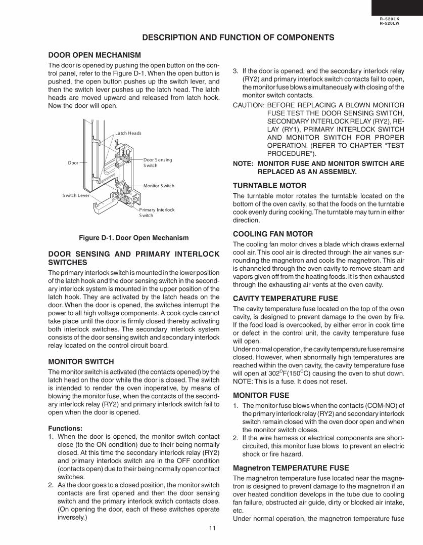
DOOR OPEN MECHANISMThedoorisopenedbypushingtheopenbuttononthecon-trolpanel,refertotheFigureD-1.Whentheopenbuttonispushed,theopenbuttonpushesuptheswitchlever,andthentheswitchleverpushesupthelatchhead.Thelatchheadsaremovedupwardand released from latchhook.Nowthedoorwillopen.
Figure D-1. Door Open Mechanism
DOOR SENSING AND PRIMARY INTERLOCK SWITCHESTheprimaryinterlockswitchismountedinthelowerpositionofthelatchhookandthedoorsensingswitchinthesecond-aryinterlocksystemismountedintheupperpositionofthelatchhook.Theyareactivatedbythelatchheadsonthedoor.Whenthedoorisopened,theswitchesinterruptthepowertoallhighvoltagecomponents.Acookcyclecannottakeplaceuntilthedoorisfirmlyclosedtherebyactivatingboth interlock switches.The secondary interlock systemconsistsofthedoorsensingswitchandsecondaryinterlockrelaylocatedonthecontrolcircuitboard.
MONITOR SWITCHThemonitorswitchisactivated(thecontactsopened)bythelatchheadonthedoorwhilethedoorisclosed.Theswitchis intended to render theoven inoperative, bymeansofblowingthemonitorfuse,whenthecontactsofthesecond-aryinterlockrelay(RY)andprimaryinterlockswitchfailtoopenwhenthedoorisopened.
Functions:1. Whenthedoor isopened, themonitorswitchcontact
close(totheONcondition)duetotheirbeingnormallyclosed.Atthistimethesecondaryinterlockrelay(RY)andprimary interlockswitchare intheOFFcondition(contactsopen)duetotheirbeingnormallyopencontactswitches.
. Asthedoorgoestoaclosedposition,themonitorswitchcontacts are first opened and then the door sensingswitchandtheprimaryinterlockswitchcontactsclose.(Onopeningthedoor,eachoftheseswitchesoperateinversely.)
3. Ifthedoorisopened,andthesecondaryinterlockrelay(RY)andprimaryinterlockswitchcontactsfailtoopen,themonitorfuseblowssimultaneouslywithclosingofthemonitorswitchcontacts.
CAUTION: BEFOREREPLACINGABLOWNMONITORFUSETESTTHEDOORSENSINGSWITCH,SECONDARYINTERLOCKRELAY(RY),RE-LAY (RY1),PRIMARY INTERLOCKSWITCHAND MONITOR SWITCH FOR PROPEROPERATION. (REFERTO CHAPTER "TESTPROCEDURE").
NOTE: MONITOR FUSE AND MONITOR SWITCH ARE REPLACED AS AN ASSEMBLY.
TURNTABLE MOTORThe turntablemotor rotates the turntable locatedon thebottomoftheovencavity,sothatthefoodsontheturntablecookevenlyduringcooking.Theturntablemayturnineitherdirection.
COOLING FAN MOTORThecoolingfanmotordrivesabladewhichdrawsexternalcoolair.Thiscoolairisdirectedthroughtheairvanessur-roundingthemagnetronandcoolsthemagnetron.Thisairischanneledthroughtheovencavitytoremovesteamandvaporsgivenofffromtheheatingfoods.Itisthenexhaustedthroughtheexhaustingairventsattheovencavity.
CAVITY TEMPERATURE FUSEThecavitytemperaturefuselocatedonthetopoftheovencavity,isdesignedtopreventdamagetotheovenbyfire.Ifthefoodloadisovercooked,byeithererrorincooktimeordefect in thecontrol unit, thecavity temperature fusewillopen.Undernormaloperation,thecavitytemperaturefuseremainsclosed.However,whenabnormallyhightemperaturesarereachedwithintheovencavity,thecavitytemperaturefusewillopenat30OF(150OC)causingtheoventoshutdown.NOTE:Thisisafuse.Itdoesnotreset.
MONITOR FUSE1. Themonitorfuseblowswhenthecontacts(COM-NO)of
theprimaryinterlockrelay(RY)andsecondaryinterlockswitchremainclosedwiththeovendooropenandwhenthemonitorswitchcloses.
. Ifthewireharnessorelectricalcomponentsareshort-circuited,thismonitorfuseblowstopreventanelectricshockorfirehazard.
Magnetron TEMPERATURE FUSEThemagnetrontemperaturefuselocatednearthemagne-tronisdesignedtopreventdamagetothemagnetronifanoverheatedconditiondevelopsinthetubeduetocoolingfanfailure,obstructedairguide,dirtyorblockedairintake,etc.Undernormaloperation,themagnetrontemperaturefuse
Door S ens ingS witch
Monitor S witch
S witch Lever
P rimary InterlockS witch
Latch Heads
Door

1
R - 520LKR-520LW
TROUBLESHOOTING GUIDE
Never touch any part in the circuit with your hand or an uninsulated tool while the power supply is con-nected.
Whentroubleshootingthemicrowaveoven,itishelpfultofollowtheSequenceofOperationinperformingthechecks.Manyofthepossiblecausesoftroublewillrequirethataspecifictestbeperformed.Thesetestsaregivenaprocedureletterwhichwillbefoundinthe"TestProcedure"section.IMPORTANT: Iftheovenbecomesinoperativebecauseofablownmonitorfuse,checkthemonitorswitch,relay(RY1)
secondaryinterlockrelay(RY),doorsensingswitchandprimaryinterlockswitchbeforereplacingthemoni-torfuse.Ifthemonitorfuseisreplaced,themonitorswitchmustalsobereplaced.UsepartFFS-BA016/KITasanassembly.
IMPORTANT: Whenevertroubleshootingisperformedwiththepowersupplycorddisconnected.Itmayin,somecases,benecessarytoconnectthepowersupplycordaftertheoutercasehasbeenremoved,inthisevent:1. Disconnectthepowersupplycord,andthenremoveoutercase.. Openthedoorandblockitopen.3. Dischargehighvoltagecapacitor.4. Disconnecttheleadstotheprimaryofthepowertransformer.5. Ensurethattheleadsremain isolatedfromothercomponentsandovenchassisbyusinginsulation
tape.6. Afterthatprocedure,reconnectthepowersupplycord.
When the testing is completed1. Disconnectthepowersupplycord,andthenremoveoutercase.. Openthedoorandblockitopen.3. Dischargehighvoltagecapacitor.4. Reconnecttheleadstotheprimaryofthepowertransformer.5. Reinstalltheoutercase(cabinet).

13
R - 520LKR-520LW
A MAGNETRON ASSEMBLY TEST
1. Disconnectthepowersupplycord,andthenremoveoutercase.. Openthedoorandblockitopen.3. Dischargehighvoltagecapacitor.
TEST PROCEDURES PROCEDURE LETTER COMPONENT TEST
Homefuseorcircuitbreakerblowswhenpowercordispluggedintowallreceptacle
C/Tfuseblowswhenpowercordispluggedintowallreceptacle.
Alllettersandindicatorsdonotap-pearindisplaywhenpowercordisfirstpluggedintowalloutlet.
Display does not operate properlywhenSTOP/CLEARkeyistouched.(Buzzershouldsoundand":"ortimeofdayshouldappearindisplay.)
Ovenlampdoesnotlightwhendoorisopened.
Oven lamp does not go out whendoorisclosed.
Ovenlamplightsbutfanmotorandturntablemotordonotoperate.
Oven does not go into cook cyclewhenSTARTpadistouched
Ovenseemstobeoperatingbutlittleornoheatisproducedinovenload.(Food incompletely cooked or notcookedatallatendofcookcycle.)
Ovengoesintoacookcyclebutex-tremelyunevenheatingisproducedinovenload(food).
OvendoesnotcookproperlywhenprogrammedforCookingPowerP-50mode.(OperatesproperlyonCookingP-HI(HIGH)mode.)
OvengoesintoCOMPUDEFROSTbutfoodisnotdefrostedwell.
AHsensordoesnotendduringsensorcookingcondition.(Ovendoesnotshutoffafteracupofwaterisboilingbysensorcooking)
Ovenstopsat16sec.afterstarting.
OFFCONDITION
PROBLEMCONDITION
PO
SS
IBLE
CA
US
E
AN
D
DE
FE
CT
IVE
PA
RT
S
TESTPROCEDURE RERE A B C D E E F F G H RERECK I CKCKCK J K LMN
COOKINGCONDITION
SENSORCOOKINGCONDITION
SH
OR
TIN
PO
WE
RC
OR
D
SH
OR
TO
RO
PE
NE
DW
IRIN
G
MA
GN
ET
RO
N
PO
WE
RT
RA
NS
FO
RM
ER
H.V
.RE
CT
IFIE
RA
SS
EM
BLY
HIG
HV
OLT
AG
EC
APA
CIT
OR
CA
VIT
YT
EM
PE
RAT
UR
EF
US
E
MA
GN
ET
RO
NT
EM
PF
US
E
SE
CO
ND
AR
YIN
TE
RLO
CK
SY
ST
EM
PR
IMA
RY
INT
ER
LOC
KS
WIT
CH
MO
NIT
OR
SW
ITC
H
MO
NIT
OR
FU
SE
OV
EN
LA
MP
OR
SO
CK
ET
CO
OLI
NG
FA
NM
OTO
R
TU
RN
TAB
LEM
OTO
R
TOU
CH
CO
NT
RO
LPA
NE
L
WR
ON
GO
PE
RAT
ION
LOW
VO
LTA
GE
DIR
TY
OV
EN
CA
VIT
Y
KE
YU
NIT
RE
LAY
(R
Y1)
CO
MP
UD
EF
RO
ST
FO
ILP
ATT
ER
NO
NP
WB
.
AH
SE
NS
OR
CK=Check/RE=Replace

14
R - 520LKR-520LW
B POWER TRANSFORMER TEST
1. Disconnectthepowersupplycord,andthenremoveoutercase.. Openthedoorandblockitopen.3. Dischargehighvoltagecapacitor.4. Disconnect theprimary input terminals andmeasure the resistanceof the transformerwithan
ohmmeter.Checkforcontinuityofthecoilswithanohmmeter.OntheRx1scale,theresistanceoftheprimarycoilshouldbelessthan1ohmandtheresistanceofthehighvoltagecoilshouldbeapproximately90ohms;theresistanceofthefilamentcoilshouldbelessthan1ohm.
5. Reconnectallleadsremovedfromcomponentsduringtesting.6. Reinstalltheoutercase(cabinet).7. Reconnectthepowersupplycordaftertheoutercaseisinstalled.8. Runtheovenandcheckallfunctions.
(HIGHVOLTAGESAREPRESENTATTHEHIGHVOLTAGETERMINAL,SODONOTATTEMPTTOMEASURETHEFILAMENTANDHIGHVOLTAGE.)
TEST PROCEDURES PROCEDURE LETTER COMPONENT TEST
4. Totestforanopenfilament,isolatethemagnetronfromthehighvoltagecircuit.Acontinuitycheckacrossthemagnetronfilamentleadsshouldindicatelessthan1ohm.
5. Totestforashortedmagnetron,connecttheohmmeterleadsbetweenthemagnetronfilamentleadsandchassisground.Thistestshouldindicateaninfiniteresistance.Ifthereislittleornoresistancethemagnetronisgroundedandmustbereplaced.
6. Reconnectallleadsremovedfromcomponentsduringtesting.7. Reinstalltheoutercase(cabinet).8. Reconnectthepowersupplycordaftertheoutercaseisinstalled.9. Runtheovenandcheckallfunctions.
MICROWAVE OUTPUT POWERThefollowingtestprocedureshouldbecarriedoutwiththemicrowaveoveninafullyassembledcondi-tion(outercasefitted).
HIGHVOLTAGESAREPRESENTDURINGTHECOOKCYCLE,SOEXTREMECAUTIONSHOULDBEOBSERVED.
Poweroutputofthemagnetroncanbemeasuredbyperformingawatertemperaturerisetest.Thistestshouldonlybeusedifabovetestsdonotindicateafaultymagnetronandthereisnodefectinthefollowingcomponentsorwiring:siliconrectifier,highvoltagecapacitorandpowertransformer.Thistestwillrequirea16ounce(453cc)measuringcupandanaccuratemercurythermometerorthermocoupletypetemperaturetester.Foraccurateresults,thefollowingproceduremustbefollowedcarefully:
1. Fillthemeasuringcupwith16oz.(453cc)oftapwaterandmeasurethetemperatureofthewaterwitha thermometeror thermocouple temperature tester.Stir the thermometeror thermocouplethroughthewateruntilthetemperaturestabilizes.Recordthetemperatureofthewater.
. Placethecupofwater intheoven.OperateovenatPOWER10(HIGH)selectingmorethan60secondscooktime.Allowthewatertoheatfor60seconds,measuringwithastopwatch,secondhandofawatchorthedigitalread-outcountdown.
3. Remove the cup from the oven and again measure the temperature, making sure to stir thethermometerorthermocouplethroughthewateruntilthemaximumtemperatureisrecorded.
4. Subtractthecoldwatertemperaturefromthehotwatertemperature.Thenormalresultshouldbe33to6OF(18.6to34.5OC)riseintemperature.Ifthewatertemperaturesareaccuratelymeasuredandtestedfortherequiredtimeperiodthetestresultswillindicateifthemagnetrontubehaslowpoweroutput(lowriseinwatertemperature)whichwouldextendcookingtimeorhighpoweroutput(highriseinwatertemperature)whichwouldreducecookingtime.Becausecookingtimecanbeadjustedtocompensateforpoweroutput,themagnetrontubeassemblyshouldbereplacedonlyifthewatertemperaturerisetestindicatesapoweroutputwellbeyondthenormallimits.Thetestisonlyaccurateifthepowersupplylinevoltageis10voltsandtheovencavityisclean.

15
R - 520LKR-520LW
TEST PROCEDURES PROCEDURE LETTER COMPONENT TEST
1. Disconnectthepowersupplycord,andthenremoveoutercase.. Openthedoorandblockitopen.3. Dischargehighvoltagecapacitor.4. Ifthecapacitorisopen,nohighvoltagewillbeavailabletothemagnetron.Disconnectinputleads
andcheckforshortoropenbetweentheterminalsusinganohmmeter. Checkingwithahighohmscale, if thehighvoltagecapacitor isnormal, themeterwill indicate
continuityforashorttimeandshouldindicateanopencircuitoncethecapacitorischarged.Iftheaboveisnotthecase,checkthecapacitorwithanohmmetertoseeifitisshortedbetweeneitheroftheterminalsandcase.Ifitisshorted,replacethecapacitor.
5. Reconnectallleadsremovedfromcomponentsduringtesting.6. Reinstalltheoutercase(cabinet).7. Reconnectthepowersupplycordaftertheoutercaseisinstalled.8. Runtheovenandcheckallfunctions.
D HIGH VOLTAGE CAPACITOR TEST
E CAVITY TEMPERATURE FUSE TEST
1. Disconnectthepowersupplycord,andthenremoveoutercase.. Openthedoorandblockitopen.3. Dischargehighvoltagecapacitor.4. Acontinuitycheckacross thecavity temperature fuse terminalsshould indicateaclosedcircuit
unlessthetemperatureofthecavitytemperaturefusereachesapproximately30OF(150OC).Anopencavitytemperaturefuseindicatesoverheatingoftheoven,exchangethecavitytemperaturefuseandcheckinsideofovencavityandforimpropersettingofcookingtimeoroperationofcontrolunit.Checkforrestrictedairflowthroughtheventholesoftheovencavity,especiallythecoolingfanandairguide.
5. Reconnectallleadsremovedfromcomponentsduringtesting.6. Reinstalltheoutercase(cabinet).7. Reconnectthepowersupplycordaftertheoutercaseisinstalled.8. Runtheovenandcheckallfunctions.
MAGNETRON TEMPERATURE FUSE TEST1. Disconnectthepowersupplycord,andthenremoveoutercase.. Openthedoorandblockitopen.3. Dischargehighvoltagecapacitor.4. Acontinuitycheckacrossthemagnetrontemperaturefuseterminalsshouldindicateaclosedcircuit
unlessthetemperatureofthemagnetrontemperaturefusereachesapproximately30OF(150OC).Anopenmagnetrontemperaturefuseindicatesoverheatingofthemagnetron.Checkforrestrictedairflowtothemagnetron,especiallythecoolingfanairguide.
5. Reconnectallleadsremovedfromcomponentsduringtesting.6. Reinstalltheoutercase(cabinet).7. Reconnectthepowersupplycordaftertheoutercaseisinstalled.
C HIGH VOLTAGE RECTIFIER TEST
1. Disconnectthepowersupplycord,andthenremoveoutercase.. Openthedoorandblockitopen.3. Dischargehighvoltagecapacitor.4. Isolatetherectifierfromthecircuit.Usingthehighestohmscaleofthemeter,readtheresistance
acrosstheterminalsandobserve,reversetheleadstotherectifierterminalsandobservemeterreading.Ifashortisindicatedinbothdirections,orifaninfiniteresistanceisreadinbothdirections,therectifierisprobablydefectiveandshouldbereplaced.
5. Reconnectallleadsremovedfromcomponentsduringtesting.6. Reinstalltheoutercase(cabinet).7. Reconnectthepowersupplycordaftertheoutercaseisinstalled.8. Runtheovenandcheckallfunctions.
NOTE: Be sure to use an ohmmeter that will supply a forward bias voltage of more than 6.3 volts.

16
R - 520LKR-520LW
TEST PROCEDURES PROCEDURE LETTER COMPONENT TEST
1. Disconnectthepowersupplycord,andthenremoveoutercase.. Openthedoorandblockitopen.3. Dischargehighvoltagecapacitor.4. Isolatetheswitchandconnecttheohmmetertothecommon(COM.)andnormallyopen(NO)terminal
oftheswitch.Themetershouldindicateanopencircuitwiththedooropenandaclosedcircuitwiththedoorclosed.Ifimproperoperationisindicated,replacetheprimaryinterlockswitch.
5. Reconnectallleadsremovedfromcomponentsduringtesting.6. Reinstalltheoutercase(cabinet).7. Reconnectthepowersupplycordaftertheoutercaseisinstalled.8. Runtheovenandcheckallfunctions.
SECONDARY INTERLOCK SYSTEM TEST
DOORSENSINGSWITCH1. Disconnectthepowersupplycord,andthenremoveoutercase.. Openthedoorandblockitopen.3. Dischargehighvoltagecapacitor.4. Isolate theswitchandconnect theohmmeter to thecommon (COM.)andnormallyopen (NO)
terminaloftheswitch.Themetershouldindicateanopencircuitwiththedooropenandaclosedcircuitwiththedoorclosed.Ifimproperoperationisindicated,replacethedoorsensingswitch.
5. Reconnectallleadsremovedfromcomponentsduringtesting.6. Reinstalltheoutercase(cabinet).7. Reconnectthepowersupplycordaftertheoutercaseisinstalled.8. Runtheovenandcheckallfunctions.
NOTE: Ifthedoorsensingswitchcontactsfailintheopenpositionandthedoorisclosed,thecoolingfan,turntableandovenlightwillbeactivatedbyRY1.
SECONDARYINTERLOCKRELAY(RY)1. Disconnectthepowersupplycord,andthenremoveoutercase.. Openthedoorandblockitopen.3. Dischargehighvoltagecapacitor.4. Disconnecttwo()wireleadsfromthemaletabterminalsoftheSecondaryInterlockRelay.Check
thestateoftherelaycontactsusingaohmmeter.Therelaycontactsshouldbeopen.Iftherelaycontactsareclosed,replacethecircuitboardentirelyortherelayitself.
5. Reconnectallleadsremovedfromcomponentsduringtesting.6. Reinstalltheoutercase(cabinet).7. Reconnectthepowersupplycordaftertheoutercaseisinstalled.8. Runtheovenandcheckallfunctions.
8. Runtheovenandcheckallfunctions.
CAUTION: IFTHETEMPERATUREFUSEINDICATESANOPENCIRCUITATROOMTEMPERATURE,REPLACETEMPERATUREFUSE.
F PRIMARY INTERLOCK SWITCH TEST

17
R - 520LKR-520LW
TEST PROCEDURES PROCEDURE LETTER COMPONENT TEST
Therefore, unlike conventional microwave ovens, proper maintenance cannot be performed with only a voltmeter and ohmmeter.Inthisservicemanual,thetouchcontrolpanelassemblyisdividedintotwounits,ControlUnitandKeyUnit,andalsotheControlUnitisdividedintotwounits,LSIUnitandPowerUnit,andtroubleshootingbyunitreplacementisdescribedaccordingtothesymptomsindicated.Before testing,
1) Disconnectthepowersupplycord,andthenremoveoutercase.) Openthedoorandblockitopen.3) Dischargehighvoltagecapacitor.4) Disconnecttheleadstotheprimaryofthepowertransformer.5) Ensure that these leads remain isolated fromothercomponentsandovenchassisbyusing
insulationtape.1. KeyUnit. NOTE;
1) Re-installtheoutercase(cabinet).) Reconnectthepowersupplycordaftertheoutercaseisinstalled.3) Runtheovenandcheckallfunctions. Thefollowingsymptomsindicateadefectivekeyunit.a) Whentouchingthepads,acertainpadproducesnosignalatall.b) Whentouchinganumberpad,twofiguresormorearedisplayed.c) Whentouchingthepads,sometimesapadproducesnosignal.
H TOUCH CONTROL PANEL ASSEMBLY TEST
1. Disconnectthepowersupplycord,andthenremoveoutercase.. Openthedoorandblockitopen.3. Dischargehighvoltagecapacitor.4. Beforeperformingthistest,makesurethattheprimaryinterlockswitchandthesecondaryinterlock
relayareoperatingproperly,accordingtotheaboveSwitchTestProcedure.Disconnectthewirelead from themonitor switch (COM) terminal.Check themonitor switchoperationbyusing theohmmeterasfollows.Whenthedoorisopen,themetershouldindicateaclosedcircuit.Whenthemonitorswitchactuatorispushedbyascrewdriverthroughthelowerlatchholeonthefrontplateoftheovencavitywiththedooropened(inthisconditiontheplungerofthemonitorswitchispushedin), themetershould indicateanopencircuit. If improperoperationis indicated,theswitchmaybedefective.Aftertestingthemonitorswitch,reconnectthewireleadtothemonitorswitch(COM)terminalandcheckthecontinuityofthemonitorcircuit.
5. Reconnectallleadsremovedfromcomponentsduringtesting.6. Reinstalltheoutercase(cabinet).7. Reconnectthepowersupplycordaftertheoutercaseisinstalled.8. Runtheovenandcheckallfunctions.
G MONITOR SWITCH TEST8. Runtheovenandcheckallfunctions.
P rimaryInterlock S witch Monitor S witch
S crew Driver
Ohmmeter
R ed White/ White

18
R - 520LKR-520LW
. ControlUnit Thefollowingsymptomsindicateadefectivecontrolunit.-1 Inconnectionwithpads.
a)Whentouchingthepads,acertaingroupofpadsdonotproduceasignal.b)Whentouchingthepads,nopadsproduceasignal.
- Inconnectionwithindicatorsa)Atacertaindigit,allorsomesegmentsdonotlightup.b)Atacertaindigit,brightnessislow.c)Onlyoneindicatordoesnotlight.d)Thecorrespondingsegmentsofalldigitsdonotlightup;ortheycontinuetolightup.e)Wrongfigureappears.f)Acertaingroupofindicatorsdonotlightup.g)Thefigureofalldigitsflicker.
-3 Otherpossibleproblemscausedbydefectivecontrolunit.a)Buzzerdoesnotsoundorcontinuestosound.b)Clockdoesnotoperateproperly.c)Cookingisnotpossible.
3. IftheKeyunitortheControlunitisdefective.1) Disconnectthepowersupplycord,andthenremoveoutercase.) Openthedoorandblockitopen.3) Dischargehighvoltagecapacitor.4) ReplacetheControlunitassembly.5) Reconnectallleadsremovedfromcomponentsduringtesting.6) Re-installtheoutercase(cabinet).7) Reconnectthepowersupplycordaftertheoutercaseisinstalled.8) Runtheovenandcheckallfunctions.
4. Whentestingiscompleted,1) Disconnectthepowersupplycord,andthenremoveoutercase.) Openthedoorandblockitopen.3) Dischargehighvoltagecapacitor.4) Reconnectallleadsremovedfromcomponentsduringtesting.5) Re-installtheoutercase(cabinet).6) Reconnectthepowersupplycordaftertheoutercaseisinstalled.7) Runtheovenandcheckallfunctions.
TEST PROCEDURES PROCEDURE LETTER COMPONENT TEST
1. Disconnectthepowersupplycord,andthenremoveoutercase.. Openthedoorandblockitopen.3. Dischargehighvoltagecapacitor.4. Usinganohmmeterandreferringtothekeyunitmatrixindicatedonthecontrolunitcircuit,check
thecircuitbetweenthepinsofthekeyunitthatcorrespondtotheSTOP/CLEARpad.Whenthepadispressed,theohmmetershouldindicateshortcircuit.Whenthepadisreleased,theohmmetershouldindicateopencircuit.Ifincorrectreadingsareobtained,thekeyunitisfaultyandmustbereplaced.Abouttheotherpads,theabovemethodmaybeused.
5. Reconnectallleadsremovedfromcomponentsduringtesting.6. Re-installtheoutercase(cabinet).7. Reconnectthepowersupplycordaftertheoutercaseisinstalled.8. Runtheovenandcheckallfunctions.
I KEY UNIT TEST

19
R - 520LKR-520LW
WARNING : Theovenshouldbefullyassembledbeforefollowingprocedure.(1)Openthedoor.()Placeonecupofwaterinthecenteroftheturntabletrayintheovencavity(3)Touchthe"Defrost"padonce.(4)Press"",thenpress"5".(5)Touchthe"START"pad.(6)TheovenisinDefrostcookingcondition.(7)Theovenwilloperateasfollows
MENU 1STSTAGE NDSTAGE 3RDSTAGESTEAKS/CHOPS LEVEL TIME LEVEL TIME LEVEL TIME
0.5lb 60% 0sec. 40% 0sec. 30% 45sec.
(8)Ifimproperoperationisindicated,thecontrolunitisprobablydefectiveandshouldbechecked.
TEST PROCEDURES PROCEDURE LETTER COMPONENT TEST
1. Disconnectthepowersupplycord,andthenremoveoutercase.. Openthedoorandblockitopen.3. Dischargehighvoltagecapacitor.4. Disconnecttheleadstotheprimaryofthepowertransformer.5. Ensurethattheseleadsremainisolatedfromothercomponentsandovenchassisbyusinginsulation
tape.6. Afterthatprocedure,re-connectthepowersupplycord.7. RemovetheoutercaseandcheckvoltagebetweenthenormalopenterminaloftherelayRY1and
thenormalopenterminaloftherelayRYonthecontrolunitwithanA.C.voltmeter. Themetershouldindicate10volts,ifnotcheckovencircuit. RY1andRYRelayTest TheserelaysareoperatedbyD.C.voltage CheckvoltageattherelaycoilwithaD.C.voltmeterduringthemicrowavecookingoperation.
DC.voltageindicated Defectiverelay.DC.voltagenotindicated Checkdiodewhichisconnectedtotherelaycoil.Ifdiodeisgood,
controlunitisdefective.
RELAYSYMBOL OPERATIONALVOLTAGE CONNECTEDCOMPONENTS
RY1 Approx.1.0VD.C. Ovenlamp/Turntablemotor/Coolingfanmotor
RY Approx.1.0VD.C. Powertransformer
8.Disconnectthepowersupplycord,andthenremoveoutercase.9.Openthedoorandblockitopen.10.Dischargehighvoltagecapacitor.11.Reconnectallleadsremovedfromcomponentsduringtesting.1.Re-installtheoutercase(cabinet).13.Reconnectthepowersupplycordaftertheoutercaseisinstalled.14.Runtheovenandcheckallfunctions.
K COMPU DEFROST TEST
KeyUnit
J RELAY TEST
PinNO.G1
PinNO.G13
Keyunitribboncable
Keyunit(MembraneSwitch)frontview
G10
G11
G12
G13
G9
G8 G7 G6 G5 G4 G3 G2 G1
9
3
6
25
80
14
7
TIMER
CLOCK
RICE
POPCORN
MINUTE PLUSSTARTSTOP
CLEARBAKED
POTATOES
FROZENENTREES
BEVERAGE
GROUNDMEAT
(SENSOR COOK)
HOT WATER
FRESHVEGETABLES
FROZENVEGETABLES
POWERLEVEL
CUSTOMHELP
KEEP WARM
PLUS
STEAKS/CHOPS
SENSORREHEAT
FISHSEAFOOD
GROUNDMEAT
(DEFROST)
FROZENROLLS/MUFFINS
BONE-INPOULTRY
FRESHROLLS/MUFFINS
BONELESSPOULTRY
CHICKENBREAST

0
R - 520LKR-520LW
TEST PROCEDURES PROCEDURE LETTER COMPONENT TEST
1. Foilpatterncheckandrepairs. 1) Disconnectthepowersupplycord,andthenremoveoutercase.
) Openthedoorandblockitopen.3) Dischargehighvoltagecapacitor.4) Followthetroubleshootingguidegivenbelowforrepair.
STEPS OCCURRENCE CAUSEORCORRECTION 1 Onlypatternat"a"isbroken. *InsertjumperwireJ1andsolder.
Patternat"a"and"b"arebroken. *InsertthecoilRCILF003YAZZbetween"c"and"d".
5) Make a visual inspection of the varistor.Checkforburneddamageandexaminethetransformerwithatesterforthepresenceoflayershort-circuit(checktheprimarycoilresistancewhichisapproximately563ý±10%).Ifanyabnormalconditionisdetected,replacethecontrolunitassembly.
6) Reconnect all leads removed fromcomponentsduringtesting.
7) Re-installtheoutercase(cabinet).8) Reconnectthepowersupplycordafterthe
outercaseisinstalled.9) Runtheovenandcheckallfunctions.
L FOIL PATTERN ON THE PRINTED WIRING BOARD TESTToprotecttheelectroniccircuits,thismodelisprovidedwithafinefoilpatternaddedtotheprimaryonthePWB,thisfoilpatternactsasafuse.
RY
2
VRS1
L1
J1
a
bc d
. Followthetroubleshootingguidegivenbelow,ifindicatordoesnotlightupafterabovecheckandrepairsarefinished.1) Disconnectthepowersupplycord,andthenremoveoutercase.) Openthedoorandblockitopen.3) Dischargehighvoltagecapacitor.4) Disconnecttheleadstotheprimaryofthepowertransformer.5) Ensure that these leads remain isolated fromothercomponentsandovenchassisbyusing
insulationtape.6) Afterthatprocedure,re-connectthepowersupplycord.7) Followthetroubleshootingguidegivenbelowforrepair.
STEPS OCCURRENCE CAUSEORCORRECTION
TheratedACvoltageisnotpresentbetween 1 thenormalopenterminaloftherelayRY1and Checksupplyvoltageandovenpowercord. thenormalopenterminaloftherelayRY.
TheratedACvoltageispresentatprimaryside Lowvoltagetransformerorsecondarycircuitdefective. oflowvoltagetransformer. Checkandreplacecontrolunitassembly.
8) Disconnectthepowersupplycord,andthenremoveoutercase. 9) Openthedoorandblockitopen. 10) Dischargehighvoltagecapacitor. 11) Reconnectallleadsremovedfromcomponentsduringtesting. 1) Re-installtheoutercase(cabinet). 13) Reconnectthepowersupplycordaftertheoutercaseisinstalled. 14) Runtheovenandcheckallfunctions.(5) Theovenwilloperateforthefirst16seconds,withoutgeneratingmicrowaveenergy.

1
R - 520LKR-520LW
WARNING :Theovenshouldbefullyassembledbeforefollowingprocedure.(1) Theovenshouldbepluggedinatleasttwominutesbeforesensorcooking.() Roomtemperatureshouldnotexceed95½F(35½C).(3) Theunitshouldnotbeinstalledinanyareawhereheatandsteamaregenerated.Theunitshould
notbe installed, forexample,next toaconventionalsurfaceunit.Refer to the“INSTALLATIONINSTRUCTIONS”oftheoperationmanual.
(4) Exhaustventsareprovidedonthebackoftheunitforpropercoolingandairflowinthecavity.Topermitadequateventilation,besuretoinstallsoasnottoblockthesevents.Thereshouldbesomespaceforaircirculation.
(5) Besuretheexteriorof thecookingcontainerandthe interiorof theovenaredry.Wipeoffanymoisturewithadryclothorpapertowel.
(6) TheSensorworkswithfoodatnormalstoragetemperature.Forexample,chickenpieceswouldbeatrefrigeratortemperatureandcannedsoupatroomtemperature.
(7) AvoidusingaerosolspraysorcleaningsolventsneartheovenwhileusingSensorsettings.Thesensorwilldetectthevaporgivenofbythesprayandturnoffbeforefoodisproperlycooked.
(8) Ifthesensorhasnotdetectedthevaporofthefood,ERRORwillappearandtheovenwillshutoff.
WaterloadcookingtestWARNING :Theovenshouldbefullyassembledbeforefollowingprocedure.Makesuretheovenhasbeenpluggedinatleasttwominutesbeforecheckingsensorcookoperation.Thecabinetshouldbeinstalledandscrewstightened.(1) Fillapproximately00milliliters(7.oz)oftapwaterina1000millilitermeasuringcup.() Placethecontaineronthecenteroftrayintheovencavity.(3) Openthedoor.(4) TouchtheTIMER/CLOCKonceandthePOWERLEVELpadtwice.Closethedoorandtouchthe
STARTpadonce.Openthedoorandtouchthenumberpads1onceandthenumberpad4once.ClosethedoorandtouchtheSTARTpad.Now,theovenisinthesensorcookingcondition,and"AH0","SENSOR"and"COOK"willappearinthedisplay.
N AH SENSOR TEST Checking the initial sensor cooking condition
(5) Theovenwilloperateforthefirst16seconds,withoutgeneratingmicrowaveenergy.NOTE:ERRORwillappearifthedoorisopenedorSTOP/CLEARpadistouchedduringfirststageof
sensorcooking.(6) Afterapproximately16seconds,microwaveenergyisproduced.IfERRORisdisplayedortheovendoesnotturnoff,replacetheAHsensororcheckthecontrolunit,refertoexplanationbelow.Iftheovenstopsafter5minutesandERRORisdisplayed,theAHsensorisnormal.CheckotherpartsexcepttheAHsensor.
TESTING METHOD FOR AH SENSOR AND/OR CONTROL UNIT
Todetermineifthesensorisdefective,thesimplestmethodistoreplaceitwithanewreplacementsensor.(1) Disconnectthepowersupplycord,andthenremoveoutercase.() Openthedoorandblockitopen.(3) Dischargehighvoltagecapacitor.(4) RemovetheAHsensor.(5) InstallthenewAHsensor.(6) Reconnectallleadsremovedfromcomponentsduringtesting.(7) Re-installtheoutercase(cabinet).(8) Reconnectthepowersupplycordaftertheoutercaseisinstalled.(9) Reconnecttheoventothepowersupplyandcheckthesensorcookoperationasfollows:
9-1.Fillapproximately00milliliters(7.oz)oftapwaterina1000millilitermeasuringcup.9-.Placethecontaineronthecenteroftrayintheovencavity.9-3.Openthedoor.9-4.TouchtheTIMER/CLOCKpadonceandthePOWERLEVELpadtwice.Closethedoorand
touchtheSTARTpadonce.Openthedoorandtouchthenumberpads1onceandthenumberpad4.ClosethedoorandthetouchtheSTARTpad.
9-5.ThecontrolpanelisinautomaticSensoroperation.

R - 520LKR-520LW
Ifnewsensordosenotoperateproperly,theproblemiswiththecontrolunit,andrefertoexplanationbelow.
CHECKING CONTROL UNIT
(1) Disconnectthepowersupplycord,andthenremoveoutercase.() Openthedoorandblockitopen.(3) Dischargehighvoltagecapacitor.(4) Disconnectthesensorconnectorthatismountedtocontrolpanel.(5) Thenconnectthedummyresistorcircuit(seefig.)tothesensorconnectorofcontrolpanel.(6) Disconnecttheleadstotheprimaryofthepowertransformer.(7) Ensurethattheseleadsremainisolatedfromothercomponentsandovenchassisbyusinginsulationtape.(8) Afterthatprocedure,re-connectthepowersupplycord.(9) Checkthesensorcookoperationproceedasfollows:
9-1.Openthedoor.TouchtheTIMER/CLOCKpadonceandthePOWERLEVELpadtwice.ClosethedoorandtouchtheSTARTpadonce.Openthedoorandtouchthenumberpads1onceandthenumberpad4.ClosethedoorandthetouchtheSTARTpad.
9-.Thecontrolpanelisinthesensorcookingoperation.9-3.Afterapproximately5seconds,pushplungerofselectswitchformorethan3seconds.Thisconditionissameas
judgementbyAHsensor.9-4.Afterapproximately3seconds,thedisplayshows“XX.XX“whichisthetimefordetectingmoisture. Iftheaboveisnotthecase,thecontrolunitisprobablydefective. Iftheaboveisproper,theAHsensorisprobablydefective.
(10)Disconnectthepowersupplycord,andthenremoveoutercase.(11)Openthedoorandblockitopen.(1)Dischargehighvoltagecapacitor.(13)Disconnectthedummyresistorcircuitfromthesensorconnectorofcontrolpanel.(14)Carryoutnecessaryrepair.(15)Reconnectallleadsremovedfromcomponentsduringtestingandrepairing.(16)Re-installtheoutercase(cabinet).(17)Reconnectthepowersupplycordaftertheoutercaseis installed.Runtheovenandcheckall
functions.(18)Carryout"Waterloadcookingtest"againandensurethattheovenworksproperly.
R1, R2 : 22Ω ± 1% 1/2W R3 : 4.3Ω ± 5% 1/4W R4 : 1MΩ ± 5% 1/4W
Sensor Dummy Resistor Circuit
Plunger
NC
NO
COM
COM NO
NCR3 R4
R1
R2
1
2
3
F-1
F-2
F-3
To connector (F)on Control Unit.
CONNECTOR

3
R - 520LKR-520LW
3) Power Source Circuit Thiscircuitgeneratesvoltagesnecessaryinthecontrol
unitfromtheAClinevoltage. Inaddition,thesynchronizingsignalisavailableinorder
tocomposeabasicstandardtimeintheclockcircuit.
Symbol Voltage Application
VSS -5V LSI(IC1)
4) Relay Circuit A circuit todrive themagnetron, fanmotor, turntable
motorandlighttheovenlamp.
5) Buzzer Circuit The buzzer is responsive to signals from the LSI to
emitaudiblesounds(keytouchsoundandcompletionsound).
6) Synchronizing Signal Circuit Thepowersourcesynchronizingsignalisavailablein
order to composeabasic standard time in the clockcircuit. It accompanies a very small error because itworksoncommercialfrequency.
7) Door Sensing Switch Aswitchto“tell”theLSIifthedoorisopenorclosed.
8) Back Light Circuit Acircuit todrive theback light (Lightemittingdiodes
LD1-LD4).
9) Night Light Circuit Acircuittodrivethelightemittingdiode(LD10).
10) Absolute Humidity Sensor Circuit Thiscircuitdetectsmoistureofthecookingfoodto allowitsautomaticcooking.
TOUCH CONTROL PANEL ASSEMBLY
OUTLINEOFTOUCHCONTROLPANEL
Thetouchcontrolsectionconsistsofthefollowingunits.
(1)KeyUnit()ControlUnit(TheControlUnitconsistsofPowerUnitand LSIUnit).
Theprincipalfunctionsoftheseunitsandthesignalscom-municatedamongthemareexplainedbelow.
Key Unit Thekeyunitiscomposedofamatrix,signalsgeneratedintheLSIaresenttothekeyunitthroughP0-P7.Whenakeypadistouched,asignaliscompletedthroughthekeyunitandpassedbacktotheLSIthroughP70,P71,P41,P45,P47andAN3toperformthefunctionthatwasrequested.
Control UnitControlunitconsistsofLSI,resetcircuit,indicatorcircuit,powersourcecircuit,relaycircuit,buzzercircuit,synchroniz-ingsignalcircuitandbacklightcircuit.
1) Reset Circuit ThiscircuitgeneratesasignalwhichresetstheLSIto
theinitialstatewhenpowerissupplied.
2) Indicator Circuit This circuit consists of segments and 3 common
electrodesusingaLiquidCrystalDisplay.

4
R - 520LKR-520LW
Maximumoutput
70%ofmaximumoutput
H:GND
L:-5V
H:GND
L:-5V
ON
ON
OFF
OFF OFF
4sec.
8sec.
1- VL-VL1 IN Power source voltage input terminal. StandardvoltageforLCD.
3-6 AN7-AN4 IN Terminal to change cooking input according to the Model. ByusingtheA/DconvertercontainedintheLSI,DCvoltageinaccordancewiththe
Modelinoperationisappliedtosetupitscookingconstant.
7 AN3 IN Signal coming from touch key. WheneitherG13lineonkeymatrixistouched,acorrespondingsignaloutofP0-P7
willbeinputintoAN3.Whennokeyistouched,thesignalisheldat“H”level.
8 AN IN To input signal which communicates the door open/close information to LSI. Doorclose"H"levelsignal(0V).DoorOpen"L"level(-5V).
9 AN1 IN Terminalnotused.
10 AN0 IN Terminalnotused.
11-13 P57-P55 OUT Terminalnotused.
14 CNTR0 OUT Signal to sound buzzer (2.0 kHz). A:keytouchsound.
B:Completionsound.
15 P53 OUT Usedforinitialbalancingofthebridgecircuit(absolutehumiditysensor).
16 P5 OUT Oven lamp, fan motor and turntable motor driving signal Toturnonandoffshutoffrelay(RY1).The
squarewaveformvoltageisdeliveredtotheRY1drivingcircuitandRYcontrolcircuit.
17 P51 OUT Usedforinitialbalancingofthebridgecircuit(absolutehumiditysensor).
18 P50 OUT Magnetron high-voltage circuit driving signal. Toturnonandoffthecookrelay(RY).The
signalsholds“L”levelduringmicrowavecook-ingand“H”levelwhilenotcooking.Inothercookingmodes(variablecooking)thesignalturns to“H” leveland“L” level inrepetitionaccordingtothepowerlevel.
19 P47 IN Signal similar to AN3. WheneitherG13lineonkeymatrixistouched,acorrespondingsignalwillbeinputinto
P46.
0 P46 OUT Terminalnotused.
1 P45 IN Signal similar to AN3. WheneitherG1lineonkeymatrixistouched,acorrespondingsignalwillbeinputinto
P45.
-3 P44-P43 OUT Terminalnotused.
4 INT0 IN Signal synchronized with commercial power source frequency. ThisisthebasictimingfortimeprocessingofLSI.
DESCRIPTION OF LSILSITheI/OsignaloftheLSIisdetailedinthefollowingtable.
Pin No. Signal I/O Description
A
B
0.1sec.
.0sec.
H:GND
L:-5V
H:GND
L:-5V
16.7msec.
Duringcooking
H:GND
L:-5V
16.7msec.
H:GND
L:-5V
5
R - 520LKR-520LW
5 P41 IN Signal similar to AN3. WheneitherG11lineonkeymatrixistouched,acorrespondingsignalwillbeinputinto
P41.
6 P40 IN ConnectedtoGNDthroughthepull-downresistor.
7 RESET IN Auto clear terminal. SignalisinputtoresettheLSItotheinitialstatewhenpowerisapplied.
8 P71 IN Signal similar to AN3. WheneitherG10lineonkeymatrixistouched,acorrespondingsignalwillbeinputinto
P71.
9 P70 IN Signal similar to ANI3. WheneitherG9lineonkeymatrixistouched,acorrespondingsignalwillbeinputinto
P70.
30 XIN IN Internal clock oscillation frequency control input setting. Theinternalclockfrequencyissetbyinsertingtheceramicfilteroscillationcircuitwith
respecttoXOUTterminal.
31 XOUT OUT Internal clock oscillation output. OutputtocontroloscillationinputtoXIN.
3 VSS IN Power source voltage : -5.0V. ThepowersourcevoltagetothedriveLSIisinputtoVSSterminal.
33 P7 OUT Key strobe signal. Signalappliedtotouch-keysection.ApulsesignalisinputtoP70,P71,P41,P45,P47
andAN3terminalwhileoneofG8linekeysonkeymatrixistouched.
34 P6 OUT Key strobe signal. Signalappliedtotouch-keysection.ApulsesignalisinputtoP70,P71,P41,P45,P47
andAN3terminalwhileoneofG7linekeysonkeymatrixistouched.
35 P5 OUT Key strobe signal. Signalappliedtotouch-keysection.ApulsesignalisinputtoP70,P71,P41,P45,P47
andAN3terminalwhileoneofG6linekeysonkeymatrixistouched.
36 P4 OUT Key strobe signal. Signalappliedtotouch-keysection.ApulsesignalisinputtoP70,P71,P41,P45,P47
andAN3terminalwhileoneofG5linekeysonkeymatrixistouched.
37 P3 OUT Key strobe signal. Signalappliedtotouch-keysection.ApulsesignalisinputtoP70,P71,P41,P45,P47
andAN3terminalwhileoneofG4linekeysonkeymatrixistouched.
38 P OUT Key strobe signal. Signalappliedtotouch-keysection.ApulsesignalisinputtoP70,P71,P41,P45,P47
andAN3terminalwhileoneofG3linekeysonkeymatrixistouched.
39 P1 OUT Key strobe signal. Signalappliedtotouch-keysection.ApulsesignalisinputtoP70,P71,P41,P45,P47
andAN3terminalwhileoneofGlinekeysonkeymatrixistouched.
40 P0 OUT Key strobe signal. Signalappliedtotouch-keysection.ApulsesignalisinputtoP70,P71,P41,P45,P47
andAN3terminalwhileoneofG1linekeysonkeymatrixistouched.
41 P17 OUT Back light signal.(Lightemittingdiodes)drivingsignal
4-46 P16-P1 OUT Terminalnotused.
47-50 SEG5-SEG OUT Terminalnotused.
51-7 SEG1-SEG0 OUT Segment data signal.
Pin No. Signal I/O Description

6
R - 520LKR-520LW
ConnectedtoLCD.
Therelationbetweensignalsareasfollows: LSIsignal(PinNo.) LCD(PinNo.) LSIsignal(PinNo.) LCD(PinNo.) SEG0(7).................................. SEG0 SEG11(61)................................SEG11 SEG1(71).................................. SEG1 SEG1(60)................................SEG1 SEG(70).................................. SEG SEG13(59)................................SEG13 SEG3(69).................................. SEG3 SEG14(58)................................SEG14 SEG4(68).................................. SEG4 SEG15(57)................................SEG15 SEG5(67).................................. SEG5 SEG16(56)................................SEG16 SEG6(66).................................. SEG6 SEG17(55)................................SEG17 SEG7(65).................................. SEG7 SEG18(54)................................SEG18 SEG8(64).................................. SEG8 SEG19(53)................................SEG19 SEG9(63).................................. SEG9 SEG0(5)................................SEG0 SEG10(6)................................. SEG10 SEG1(51)................................SEG1
73 VCC IN Powersourcevoltage:GND(0V).
74 VREF IN A/D converter power source voltage : GND(0V). ThepowersourcevoltagetodrivetheA/Dconverter.ConnectedtoGND.
75 AVSS IN A/D converter power source voltage : -5.0V. ThepowersourcevoltagetodrivetheA/Dconverter.
76 COM3 OUT Terminalnotused.
77 COM OUT Common data signal. ConnectedtoLCDsignalCOM1.
78 COM1 OUT Common data signal. ConnectedtoLCDsignalCOM.
79 COM0 OUT Common data signal. ConnectedtoLCDsignalCOM3.
80 VL3 IN Power source voltage input terminal. StandardvoltageforLCD.ConnectedtoGND.
Pin No. Signal I/O Description

7
R - 520LKR-520LW
(1) Structure of Absolute Humidity Sensor Theabsolutehumiditysensorincludestwothermistors
asshownintheillustration.Onethermistorishousedintheclosedvesselfilledwithdryairwhileanotherintheopenvessel.Eachsensorisprovidedwiththeprotectivecovermadeofmetalmesh tobeprotected from theexternalairflow.
(2) Operational Principle of Absolute Humidity Sensor
The figure below shows the basic structure of anabsolutehumiditysensor.Abridgecircuitisformedbytwothermistorsandtworesistors(R1andR).
Theoutputofthebridgecircuitistobeamplifiedbytheoperationalamplifier.
Eachthermistorissuppliedwithacurrenttokeepitheatedatabout150½C(30½F),theresultantheatisdissipatedintheairandifthetwothermistorsareplacedindifferenthumidityconditionstheyshowdifferentdegreesofheatconductivityleadingtoapotentialdifferencebetweenthemcausinganoutputvoltagefromthebridgecircuit,the intensity of which is increased as the absolutehumidityoftheairincreases.Sincetheoutputisveryminute,itisamplifiedbytheoperationalamplifier.
(3) Detector Circuit of Absolute Humidity Sensor Circuit
ThisdetectorcircuitisusedtodetecttheoutputvoltageoftheabsolutehumiditycircuittoallowtheLSItocontrolsensor cooking of the unit. When the unit is set inthesensorcookingmode,16secondsclearingcycleoccursthanthedetectorcircuitstartstofunctionandtheLSIobservestheinitialvoltageavailableatitsAN1terminal.
Withthisvoltagegiven,theswitchesSW1toSW5intheLSIareturnedoninsuchawayastochangetheresistancevaluesinparallelwithR98~R10.ChangingtheresistancevaluesresultsinthatthereisthesamepotentialatbothF-3terminaloftheabsolutehumiditysensorandAN0terminaloftheLSI.ThevoltageofAN1terminalwillindicateabout-.5V.Thisinitialbalancingissetupabout16secondsaftertheunitisputintheSensorCookingmode.Asthesensorcookingproceeds,
ABSOLUTE HUMIDITY SENSOR CIRCUIT
thefoodisheatedtogeneratemoisturebywhichtheresistancebalanceofthebridgecircuitisdeviatedtoincreasethevoltageavailableatAN1terminalof theLSI.
Then the LSI observes that voltage at AN1 terminaland compares it with its initial value, and when thecomparison rate reaches the preset value (fixed foreachmenutobecooked),theLSIcausestheunittostopsensorcooking;thereafter,theunitgoesinthenextoperationautomatically.
WhentheLSIstartstodetecttheinitialvoltageatAN1terminal16secondsaftertheunithasbeenputintheSensorCookingmode,ifitisnotpossibletobalancethebridgecircuitduetodisconnectionoftheabsolutehumiditysensor,ERRORwillappearonthedisplayandthecookingisstopped.
ventilation opening for sensing Sensing part(Open vessel)
Sensing part(Closed vessel)
Thermistors
C
S
R3
R1
R2
+
Operationalamplifier
Outputvoltage
S : Thermistoropen vessel
C : Thermistorclosed vessel
2Absolute humidity (g/m )
Out
putv
olta
ge
Absolute humidity vs,output voltage characteristic
SW1
SW2
SW3
SW4
SW5
P57
P56
P55
P51
P53
LSI(IC1)
AN0
AN1
620k
300k
150k
75k
37.4k
11
17
15
10
9
13
12
47k
47k
10k1 2 3 4
8 7 6 5
0.01
uF
0.01
5uF
0.01
uF
VA : -15V VA : -15V
R90
C90
C91
C93
C92
S
F-2 1.8k IC2
F-1
F-3C
3.57k
3.32k
VC : -5V
0.1
uF
C. Thermistor inclosed vessel
S. Thermistor inopen vessel
R98
R99
R96
R91
360kR93R92
R94 R95
D90
R100
R101
R102
R97

8
R - 520LKR-520LW
1. Precautions for Handling Electronic Components ThisunitusesCMOSLSIintheintegralpartofthecircuits.
Whenhandling theseparts, the followingprecautionsshouldbestrictlyfollowed.CMOSLSIhaveextremelyhigh impedanceat its inputandoutput terminals.Forthis reason, it iseasily influencedby thesurroundinghighvoltagepowersource,staticelectricitycharge inclothes,etc.andsometimesitisnotfullyprotectedbythebuilt-inprotectioncircuit.
InordertoprotectCMOSLSI.1) Whenstoringandtransporting,thoroughlywrapthem
inaluminiumfoil.AlsowrapallPWboardscontainingtheminaluminiumfoil.
) When soldering, ground the technician as shown inthefigureandusegroundedsoldering ironandwork
TOUCH CONTROL PANEL SERVICING
6) Runtheovenandcheckallfunctions.A. Onsomemodels,thepowersupplycordbetweenthe
touchcontrolpanelandtheovenitselfissoshortthatthetwocan’tbeseparated.Forthosemodels,checkandrepairallthecontrols(sensor-relatedonesincluded)ofthetouchcontrolpanelwhilekeeping itconnectedtotheoven.
B. Onsomemodels,thepowersupplycordbetweenthetouchcontrolpanelandtheovenproperislongenoughthattheymaybeseparatedfromeachother.Forthosemodels,itispossibletocheckandrepairthecontrolsofthetouchcontrolpanelwhilekeepingitapartfromtheovenproper;inthiscaseyoumustshortbothendsofthedoorsensingswitch(onPWB)ofthetouchcontrolpanelwithajumper,whichactivatesanoperationalstatethatisequivalenttotheovendoorbeingclosed.Asforthesensor-relatedcontrolsofthetouchcontrolpanel,checking them is possible if dummy resistor(s) withresistanceequaltothatofthecontrolsareused.
(2) Servicing the touch control panel with power supply from an external power source:
Disconnectthetouchcontrolpanelcompletelyfromtheovenproper,andshortbothendsofthedoorsensingswitch (on PWB) of the touch control panel, whichactivatesanoperationalstatethatisequivalenttotheoven door being closed. Connect an external powersourcetothepowerinputterminalofthetouchcontrolpanel,thenitispossibletocheckandrepairthecontrolsof thetouchcontrolpanel it isalsopossibletocheckthesensor-relatedcontrolsofthetouchcontrolpanelbyusingthedummyresistor(s).
3. Servicing Tools Tools required to service the touch control panel
assembly.1)Solderingiron:30W (It is recommended to use a soldering iron with a
groundingterminal.))Oscilloscope:Singlebeam,frequencyrange:DC-10MHz
typeormoreadvancedmodel.3)Others:Handtools
4. Other Precautions1) Beforeturningonthepowersourceofthecontrolunit,
removethealuminiumfoilappliedforpreventingstaticelectricity.
) Connect theconnectorsof thekeyunit to thecontrolunitbeingsurethattheleadwiresarenottwisted.
3)Afteraluminiumfoilisremoved,becarefulthatabnormalvoltageduetostaticelectricityetc.isnotappliedtotheinputoroutputterminals.
4)Attachconnectors,electrolyticcapacitors,etc.toPWB,makingsurethatallconnectionsaretight.
table.
2. Servicing of Touch Control Panel Wedescribetheprocedurestopermitservicingofthe
touch control panel of the microwave oven and theprecautionsyoumusttakewhendoingso.Toperformtheservicing,powertothetouchcontrolpanelisavailableeitherfromthepowerlineoftheovenitselforfromanexternalpowersource.
(1) Servicing the touch control panel with power supply of the oven:
CAUTION: THE HIGH VOLTAGE TRANSFORMER OF THE
MICROWAVE OVEN IS STILL LIVE DURING SERVICING AND PRESENTS A HAZARD.
Therefore,beforecheckingtheperformanceofthetouchcontrolpanel,1) Disconnectthepowersupplycord,andthenremove
outercase.) Openthedoorandblockitopen.3) Dischargehighvoltagecapacitor.4) Disconnect the leads to the primary of the power
transformer.5) Ensurethattheseleadsremainisolatedfromother
componentsandovenchassisbyusing insulationtape.
6) After thatprocedure, re-connect thepowersupplycord.
After checking the performance of the touch controlpanel,
1) Disconnectthepowersupplycord.) Openthedoorandblockitopen.3) Re-connect the leads to theprimaryof thepower
transformer.4) Re-installtheoutercase(cabinet).5) Re-connect the power supply cord after the outer
caseisinstalled.
approx.1Mohm

9
R - 520LKR-520LW
Toremovetheoutercase,proceedasfollows.1.Disconnectthepowersupplycord.. Opentheovendoorandblockitopen.3.Remove the two()screws fromthe lowerportionof
therearcabinetusingaT0HTorxtypeorGTXH0-100screwdriver.
4. Removetheremainingtwo()screwsfromrear.5.Slidetheentireoutercasebackoutabout1inch(3cm)
tofreeitfromretainingclipsonthecavityfaceplate.6.Liftentireoutercasefromtheunit.
mayresultinsevere,possiblyfatal,electricshock.(Example)HighVoltage Capacitor, PowerTransformer, Magnetron, HighVoltage Rectifier Assembly, HighVoltage Harnessetc..
WARNING: To Avoid possible exposure to microwave energy, please follow the instructions below
before operating the oven.
WARNING AGAINST HIGH VOLTAGE:Microwaveovenscontaincircuitrycapableofproducingveryhighvoltageandcurrent.Contactwiththefollowingparts
OUTER CASE REMOVAL
COMPONENT REPLACEMENT AND ADJUSTMENT PROCEDURE
To prevent an electric shock, take the following pre-cautions:1. Beforewiring:
1) Disconnectthepowersupplycord.) Openthedoorblockitopen.3) Wait 60seconds, thendischarge thehighvoltage
capacitor.. Don’tletthewireleadstouchtothefollowingparts:
1) Highvoltageparts: Magnetron,Highvoltagetransformer,Highvoltage
capacitorandHighvoltagerectifierassembly.) Hotparts: Ovenlamp,Magnetron,Highvoltagetransformerand
Ovencavity.
WARNING FOR WIRING
1. Disconnectthepowersupplycord.. Makesure thatadefinite”click”canbeheardwhen
themicrowaveovendoorisunlatched.(Holdthedoorinaclosedpositionwithonehand,thenpushthedooropenbuttonwiththeother,thiscausesthelatchleadstorise,itisthenpossibletoheara“click’asthedoorswitchesoperate.)
3. Visuallycheckthedoorandcavityfaceplatefordamage(dents,cracks,signsofarcingetc.).
Carry out any remedial work that is necessary beforeoperatingtheoven.Donotoperatetheovenifanyofthefollowingconditionsexist:
1. Doordoesnotclosefirmly.. Doorhinge,supportorlatchhookisdamaged.3. Thedoorgasketorsealisdamaged.4. Thedoorisbentorwarped.5. There are defective parts in the door interlock
system.6. Therearedefectivepartsinthemicrowavegenerating
andtransmissionassembly.7. Thereisvisibledamagetotheoven.
Donotoperatetheoven:1. WithouttheRFgasket(Magnetron).. Ifthewaveguideorovencavityarenotintact.3. Ifthedoorisnotclosed.4. Iftheoutercase(cabinet)isnotfitted.
3) Sharpedge: Bottom plate, Oven cavity, Waveguide flange,
Chassissupportandothermetallicplate.4) Movableparts(topreventafault): Fanblade,Fanmotor,Switch,Switchlever,Open
button.3. Donotcatchthewireleadsintheoutercasecabinet.4. Insertthepositivelockconnectoruntilitspinislocked
andmakesurethat thewire leadsdonot comeoffevenifthewireleadsarepulled.
5. Topreventanerror function,connect thewire leadscorrectly,referringtothePictorialDiagram.
Pleasereferto‘OVENPARTS,CABINETPARTS,CONTROLPANELPARTS,DOORPARTS’,whencarryingoutanyofthefollowingremovalprocedures:
30
R - 520LKR-520LW
POWER TRANSFORMER REMOVALRe-install1. Rest transformeron thebottomplatewith itsprimary
terminalstowardtheovenfaceplate.. Securetransformerwithfourscrewstobottomplate.3. Re-connect wire leads (primary and high voltage) to
power transformer and filament leads of transformerto magnetron and high voltage capacitor. Refer to"PICTORIALDIAGRAM"onpage30.
4. Re-installoutercaseandcheckthatovenisoperatingproperly.
1. Disconnectthepowersupplycordandthenremoveoutercase.
. Opentheovendoorandblockitopen.3. Dischargehighvoltagecapacitor.4. Disconnectwireleads(primaryandhighvoltage)from
power transformer and the filament leads from themagnetronandcapacitorterminals.
5. Removetwo()screwsholdingtransformertobottomplate.
6. Removetransformerfrombottomplate.
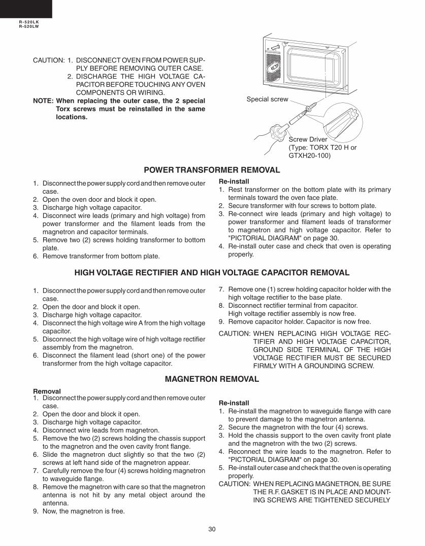
CAUTION: 1. DISCONNECTOVENFROMPOWERSUP-PLYBEFOREREMOVINGOUTERCASE.
. DISCHARGE THE HIGH VOLTAGE CA-PACITORBEFORETOUCHINGANYOVENCOMPONENTSORWIRING.
NOTE: When replacing the outer case, the 2 special Torx screws must be reinstalled in the same locations.
HIGH VOLTAGE RECTIFIER AND HIGH VOLTAGE CAPACITOR REMOVAL
1.Disconnectthepowersupplycordandthenremoveoutercase.
. Openthedoorandblockitopen.3.Dischargehighvoltagecapacitor.4.DisconnectthehighvoltagewireAfromthehighvoltage
capacitor.5.Disconnectthehighvoltagewireofhighvoltagerectifier
assemblyfromthemagnetron.6.Disconnectthefilamentlead(shortone)ofthepower
transformerfromthehighvoltagecapacitor.
7.Removeone(1)screwholdingcapacitorholderwiththehighvoltagerectifiertothebaseplate.
8.Disconnectrectifierterminalfromcapacitor. Highvoltagerectifierassemblyisnowfree.9.Removecapacitorholder.Capacitorisnowfree.
CAUTION:WHEN REPLACING HIGH VOLTAGE REC-TIFIER AND HIGH VOLTAGE CAPACITOR,GROUND SIDE TERMINAL OF THE HIGHVOLTAGERECTIFIERMUSTBESECUREDFIRMLYWITHAGROUNDINGSCREW.
MAGNETRON REMOVALRemoval1.Disconnectthepowersupplycordandthenremoveouter
case.. Openthedoorandblockitopen.3.Dischargehighvoltagecapacitor.4.Disconnectwireleadsfrommagnetron.5.Removethetwo()screwsholdingthechassissupport
tothemagnetronandtheovencavityfrontflange.6.Slide the magnetron duct slightly so that the two ()
screwsatlefthandsideofthemagnetronappear.7.Carefullyremovethefour(4)screwsholdingmagnetron
towaveguideflange.8. Removethemagnetronwithcaresothatthemagnetron
antenna is not hit by any metal object around theantenna.
9.Now,themagnetronisfree.
Re-install1. Re-installthemagnetrontowaveguideflangewithcare
topreventdamagetothemagnetronantenna.. Securethemagnetronwiththefour(4)screws.3. Holdthechassissupporttotheovencavityfrontplate
andthemagnetronwiththetwo()screws.4.Reconnect thewire leads to themagnetron.Refer to
"PICTORIALDIAGRAM"onpage30.5. Re-installoutercaseandcheckthattheovenisoperating
properly.CAUTION: WHENREPLACINGMAGNETRON,BESURE
THER.F.GASKETISINPLACEANDMOUNT-INGSCREWSARETIGHTENEDSECURELY
Special screw
Screw Driver(Type: TORX T20 H orGTXH20-100)

31
R - 520LKR-520LW
POSITIVE LOCK® CONNECTOR (NO-CASE TYPE) REMOVAL
Figure C-2. Positive lock® connector
1. Disconnect the power supply cord, and then removeoutercase.
. Openthedoorandblockitopen.3. Dischargehighvoltagecapacitor.4. Pushtheleverofpositivelock®connector.5. Pulldownonthepositivelock®connector.
CAUTION: WHENCONNECTINGTHEPOSITIVELOCK®CONNECTORSTOTHETERMINALS,CON-NECTTHEPOSITIVELOCK®SOTHATTHELEVERFACESYOU.
1.Disconnect the power supply cord and remove outercase.
. Openthedoorandblockitopen.3.Dischargehighvoltagecapacitor.4. Removetheovenlampfromtheovenlampsocket.5.Pullthewireleadsfromtheovenlampsocketbypushing
theterminalholeoftheovenlampsocketwiththesmallflattypescrewdriver.
6.Removetheovenlampsocketfromthemagnetronductbyturningthesocketcounterclockwise.
7. Removetheovenlampfromthesocketbyturningtheovenlamp.
OVEN LAMP AND LAMP SOCKET REMOVAL
8. Now, the oven lamp and the oven lamp socket are
CONTROL PANEL ASSEMBLY REMOVAL
1. Disconnectthepowersupplycordandthenremoveoutercase.
. Openthedoorandblockitopen.3. Dischargehighvoltagecapacitor.4. Disconnectthewireleadsfrompanelcomponents.5. Remove the one (1) screw holding the control panel
assemblytotheovencavityfrontplate.6. Slidethecontrolpanelassemblyupwardandremove
it.7. Now,individualcomponentscanberemoved.
NOTE:1. Beforeattachinganewkeyunit,wipeoffremainingadhesive on the control panel frame surfacescompletelywithasoftclothsoakedinalcohol.
.Whenattachingthekeyunittothecontrolpanelframe,adjusttheupperedgeandrightedgeofthekeyunittothecorrectpositionofcontrolpanelframe.
3.Placethekeyunitfirmlytothecontrolpanelframebyrubbingwithsoftclothnottoscratch.
Removal1. Disconnectthepowersupplycordandthenremoveoutercase.. Openthedoorandblockitopen.3. Dischargehighvoltagecapacitor.4. Removethecontrolpanelassembly,referringtochapterofCONTROLPANELASSEMBLYREMOVAL.5. Removethethree(3)screwsholdingthecontrolunittothecontrolpanelframe.Andremovethecontrolunitbyreleasingfrom
tabs.6. Removetherubberconnectorfromthelongslitonthecontrolpanelframe.7. Removethenightlightcover(releasetabsfrombackside).8. Removethegraphicsheetfromthecontrolpanelframe.(*Seespecialnote)9. Removeawaythemembraneswitchfromthecontrolpanelframe.(*Seespecialnote)
Figure C-XXX Graphic Sheet and Membrane Switch Replacement
GRAPHIC SHEET AND MEMBRANE SWITCH REPLACEMENT
Oven lampsocket
Terminal

3
R - 520LKR-520LW
.Remove turntable and turntable support from ovencavity.
3.Laytheovenonit'sbackside.Removetheturntablemotorcoverbysnippingoffthematerialinfourcorners.
4. Wherethecornershavebeensnippedoffbendcornerareasflat.Nosharpedgesmustbeevidentafterremovaloftheturntablemotorcover.
TURNTABLE MOTOR REMOVAL1.Disconnectthepowersupplycord.
5.Disconnectwireleadsfromturntablemotor. (See"Positivelockconnectorremoval")6.Removeone(1)screwholdingturntablemotortooven
cavity.7.Nowtheturntablemotorisfree.8. Afterreplacement,usetheone(1)screwprovidedwith
theTTMKit,toattachtheturntablemotorcover.
Installation1.Removeremainingadhesiveonthecontrolpanelframesurfaceswithasoftclothsoakedinalcohol..MakesurethattheLCDsheetandtheliquidcrystaldisplayisinstalledinposition.3.Removethebackingpaperfromthenewmembraneswitchandribboncable.4.Inserttheribboncableofthemembraneswitchintotheslitofthecontrolpanelframe.5.Adjusttheupperedgeandrightedgeofthemembraneswitchtothesmalldepressiononthesurfaceofthecontrol
panelframe.6.Attachthemembraneswitchtothecontrolpanelframebyrubbingwithasoftclothnottoscratch.7.Removethebackingpaperfromthenewgraphicsheet.8.Adjusttheupperedgeandrightedgeofthegraphicsheettothelargedepressiononthesurfaceofthecontrolpanel
frame.9.Attachthegraphicsheettothecontrolpanelframebyrubbingwithasoftclothnottoscratch.10.Attachtheribboncabletothecontrolpanelframerearside.11.Placetheedgeofthemembraneswitch’sribboncableonthelowerportionoftheliquidcrystaldisplay.1.Inserttherubberconnectorintothelongslitonthecontrolpanelframe.13.Reinstallthecontrolunittothecontrolpanelframewiththethree(3)screws.NOTE:Do not touch the contact surface of the ribbon cable (edge) and the rubber connector with a finger directly not to be oxidized.If display digits are missing or scrambled, remove control unit and make sure that there is not any trash or foreign substance on the contact surface of the rubber connector. Use an adhesive tape to clean the contact surface of the rubber connector. (* Heat gun will soften adhesive.)
Rubber connectorContact surface
Contactsurface
Ribbon cableof membraneswitch
Liquid crystal display
Liquid crystal display
Ribboncable
Graphicsheet
Membraneswitch
LCD sheet
Control panel frame(Rear side)
Control panel frame
Long slitSlit

33
R - 520LKR-520LW
COOLING FAN MOTOR REMOVALREMOVAL1.Disconnectthepowersupplycordandthenremoveouter
case.. Openthedoorandblockitopen.3.Dischargehighvoltagecapacitor.4.Disconnectthewireleadsfromthefanmotor.5.Removethetwo()screwsholdingthefanmotortothe
ovencavitybackplate.6. Removethefanbladefromthefanmotorshaftaccording
tothefollowingprocedure.7. Holdtheedgeoftherotorofthefanmotorbyusinga
pairofgroovejointpliers.CAUTION: * Make sure that no metal pieces enter the gap between
the rotor and the stator of the fan motor because the rotor is easily shaven by pliers and metal pieces may be produced.
* Do not touch the pliers to the coil of the fan motor because the coil may be cut or injured.
* Do not disfigure the bracket by touching with the pliers.
8. Removethefanbladefromtheshaftofthefanmotorbypullingandrotatingthefanbladewithyourhand.
9. Now,thefanbladeandthefanmotorwillbefree.
CAUTION:* Do not reuse the removed fan blade because the
hole (for shaft) may be larger than normal.
INSTALLATION1. Installthefanbladetothefanmotorshaftaccordingto
thefollowingprocedure.. Holdthecenterofthebracketwhichsupportstheshaft
ofthefanmotorontheflattable.3. Applythescrewlocktightintothehole(forshaft)ofthe
fanblade.4. Installthefanbladetotheshaftoffanmotorbypushing
thefanbladewithasmall,lightweight,ballpeenhammerorrubbermallet.
CAUTION:* Do not hit the fan blade strongly when installed
because the bracket may be disfigured.* Make sure that the fan blade rotates smooth after
installation.* Make sure that the axis of the shaft is not slanted.5. Installthefanmotortotheovencavitybackplatewith
thetwo()screws.6. Connectthewireleadstothefanmotor,referringtothe
pictorialdiagram.
DOOR SENSING SWITCH/PRIMARY INTERLOCK SWITCH AND MONITOR SWITCH REMOVAL1. Disconnect the power supply cord and remove outer
case.. Openthedoorandblockitopen.3. Dischargehighvoltagecapacitor.4. Disconnectwireleadsfromtheswitches.5. Removetwo()screwsholdinglatchhooktoovenflange.6. Removelatchhookassemblyfromovenflange.7. Pushoutwardonthetwo()retainingtabsholdingswitch
inplace.
8. Switchisnowfree. Atthistimeswitchleverwillbefree,donotloseit.Re-install1. Re-installeachswitchinitsplace.Theprimaryinterlock/
monitorswitchesareinthelowerpositionandthedoorsensingswitchisintheupperposition.
. Re-connectwireleadstoeachswitch.
Side ViewRear View
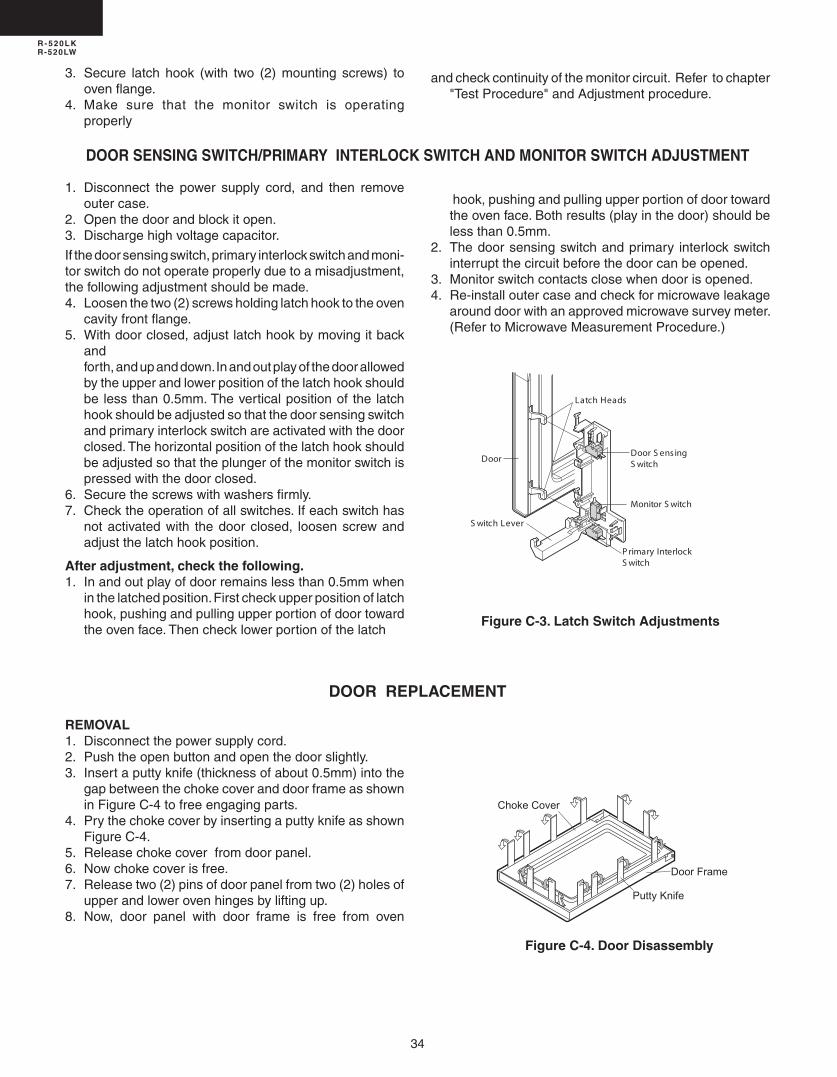
34
R - 520LKR-520LW
3. Secure latch hook (with two () mounting screws) toovenflange.
4. Make sure that the monitor switch is operatingproperly
andcheckcontinuityofthemonitorcircuit.Refertochapter"TestProcedure"andAdjustmentprocedure.
DOOR SENSING SWITCH/PRIMARY INTERLOCK SWITCH AND MONITOR SWITCH ADJUSTMENT
1. Disconnect the power supply cord, and then removeoutercase.
. Openthedoorandblockitopen.3. Dischargehighvoltagecapacitor.
Ifthedoorsensingswitch,primaryinterlockswitchandmoni-torswitchdonotoperateproperlyduetoamisadjustment,thefollowingadjustmentshouldbemade.4. Loosenthetwo()screwsholdinglatchhooktotheoven
cavityfrontflange.5. Withdoorclosed,adjustlatchhookbymovingitback
and forth,andupanddown.Inandoutplayofthedoorallowed
bytheupperandlowerpositionofthelatchhookshouldbe lessthan0.5mm.Theverticalpositionof the latchhookshouldbeadjustedsothatthedoorsensingswitchandprimaryinterlockswitchareactivatedwiththedoorclosed.Thehorizontalpositionofthelatchhookshouldbeadjustedsothattheplungerofthemonitorswitchispressedwiththedoorclosed.
6. Securethescrewswithwashersfirmly.7. Checktheoperationofallswitches.Ifeachswitchhas
notactivatedwith thedoorclosed, loosenscrewandadjustthelatchhookposition.
After adjustment, check the following. 1. Inandoutplayofdoorremainslessthan0.5mmwhen
inthelatchedposition.Firstcheckupperpositionoflatchhook,pushingandpullingupperportionofdoortowardtheovenface.Thenchecklowerportionofthelatch
Figure C-3. Latch Switch Adjustments
hook,pushingandpullingupperportionofdoortowardtheovenface.Bothresults(playinthedoor)shouldbelessthan0.5mm.
. Thedoorsensingswitchandprimary interlockswitchinterruptthecircuitbeforethedoorcanbeopened.
3. Monitorswitchcontactsclosewhendoorisopened.4. Re-installoutercaseandcheckformicrowaveleakage
arounddoorwithanapprovedmicrowavesurveymeter.(RefertoMicrowaveMeasurementProcedure.)
DOOR REPLACEMENT
Figure C-4. Door Disassembly
REMOVAL1. Disconnectthepowersupplycord.. Pushtheopenbuttonandopenthedoorslightly.3. Insertaputtyknife(thicknessofabout0.5mm)intothe
gapbetweenthechokecoveranddoorframeasshowninFigureC-4tofreeengagingparts.
4. PrythechokecoverbyinsertingaputtyknifeasshownFigureC-4.
5. Releasechokecoverfromdoorpanel.6. Nowchokecoverisfree.7. Releasetwo()pinsofdoorpanelfromtwo()holesof
upperandlowerovenhingesbyliftingup.8. Now, door panel with door frame is free from oven
Door S ens ingS witch
Monitor S witch
S witch Lever
P rimary InterlockS witch
Latch Heads
Door
Choke Cover
Door Frame
Putty Knife

35
R - 520LKR-520LW
9. Releasethedoorpanelfromtwelve(1)tabsofdoorframe.
10.Removethedoorpanelfromthedoorframe.11.Now,doorpanelwithsealerfilmisfree.1.Tearsealerfilmfromdoorpanel.13.Now,doorpanelisfree.14.Slidelatchheadupwardandremoveitfromdoorframe
with releasing latchspring fromdoor frameand latchhead.
15.Now,latchheadandlatchspringarefree.16.Removedoorscreenfromdoorframe17.Now,doorframeisfree.
RE-INSTALL1. Re-installdoorscreentodoorframe.. Re-installthelatchspringtothelatchhead.Re-install
thelatchspringtothedoorframe.Re-installlatchheadtodoorframe.
3. Re-installdoorpaneltodoorframebyfittingtwelve(1)tabsofdoorframetotwelve(1)holesofdoorpanel.
4. Putsealerfilmondoorpanel.Referto“SealerFilm”abouthowtohandlenewone.
5. Catchtwo()pinsofdoorpanelontwo()holeofupperandlowerovenhinges.
6. Re-installchokecovertodoorpanelbypushing.
Note: After any service to the door;(A) Make sure that door sensing switch and primary
interlock switch are operating properly. (Refer to chapter “Test Procedures”.).
(B) An approved microwave survey meter should be used to assure compliance with proper microwave radiation emission limitation standards.
After any service, make sure of the following :1. Door latch heads smoothly catch latch hook through
latchholesandthatlatchheadgoesthroughcenteroflatchhole.
. Deviationofdooralignmentfromhorizontallineofcavityfaceplateistobelessthan1.0mm.
3. Door ispositionedwith itsfacepressedtowardcavityfaceplate.
4. Check for microwave leakage around door with anapprovedmicrowavesurveymeter.(RefertoMicrowaveMeasurementProcedure.)
Note: Thedooronamicrowaveovenisdesignedtoactas an electronic seal preventing the leakage ofmicrowave energy from oven cavity during cookcycle.Thisfunctiondoesnotrequirethatdoorbeair-tight,moisture(condensation)-tightorlight-tight.Therefore,occasionalappearanceofmoisture,lightor sensingof gentlewarmairmovement aroundovendoorisnotabnormalanddonotofthemselvesindicatealeakageofmicrowaveenergyfromovencavity.
SEALER FILMInstallation1. Puttheadhesivetapeonthebackingfilmofthesealer
filmasshowninFig.C-6.. Tearthebackingfilmbypullingtheadhesivetape.3. Put the pasted side of the sealer film on the door
panel
Note:
Whencarringoutanyrepairtothedoor,donotbendorwraptheslitchoke(tabsonthedoorpanelassembly)topreventmicrowaveleakage.

36
R - 520LKR-520LW
64 51 2 3
64 51 2 3
A
B
C
D
E
F
G
H
A
B
C
D
E
F
G
H
Fig
ure
S-1
. Pic
tori
al D
iag
ram
HIG
HV
OLT
AG
EC
AP
AC
ITO
R
HIG
HV
OLT
AG
EW
IRE
A
H.V
.RE
CT
IFIE
R
HIG
HV
OLT
AG
EC
OM
PO
NE
NT
SO
VE
NLA
MP
AN
DS
OC
KE
T
MA
GN
ET
RO
N
CO
M.
MONITORSWITCH
N.C
.
PR
IMA
RY
SW
ITC
H
TU
RN
TA
BLE
MO
TO
R
PO
WE
RT
RA
NS
FO
RM
ER
CO
M.
NO
WH
T
RE
D
RED
OR
GG
RY
OR
G
WH
T
WH
T
WH
T
RE
D
RE
DCA
VIT
YT
EM
P.F
US
E
MA
GN
ET
RO
NT
EM
PF
US
E
FA
NM
OT
OR
RE
D
WH
T
WH
T
PO
WE
RS
UP
PLY
CO
RD
120V
60H
z
NO
TE
:T
hene
utra
l(W
HT
/GR
Y)
wire
mus
tbe
conn
ecte
dto
the
term
inal
with
"N"
mar
kon
the
pow
ersu
pply
cord
.
BLK
WH
TH
NN
OT
E:
The
grou
ndin
gco
nduc
tor
ofth
epo
wer
supp
lyco
rdha
sbe
engr
ound
edby
pow
ersu
pply
cord
fixin
gsc
rew
.T
hesc
rew
mus
tal
way
sbe
kept
tight
.
CO
M.
N.O
.D
OO
RS
EN
SIN
GS
WIT
CH
PN
K
GR
N
GR
Nto
Ove
nca
vity
GR
N
PN
K
GR
N2 1
CN
-B
BR
N
WH
T
OR
G
RE
D
GR
Y
WH
T
BLK
RE
D
CO
M.
COM.
N.O
.N.O.
WH
T
RY
1
RY2
SE
CO
ND
AR
YIN
TE
RLO
CK
RE
LAY
T1
12
(PO
WE
RU
NIT
)
CN
-B
OR
G
WH
T
GR
Y
OR
G
OR
G
WH
T
GR
Y
WH
T
RE
D
BR
N
BLK
AH
SE
NS
OR
RE
D
WH
T
1 2 3
CN
-F

37
R - 520LKR-520LW
64 51 2 3
64 51 2 3
A
B
C
D
E
F
G
H
A
B
C
D
E
F
G
H
Fig
ure
S-3
. Co
ntr
ol U
nit
Cir
cuit

38
R - 520LKR-520LW
64 51 2 3
64 51 2 3
A
B
C
D
E
F
G
H
A
B
C
D
E
F
G
H
Figure S-5 . Printed Wiring Board of Power Unit
RY1
RY
2
EC
B
EC
B
EC
B
VRS1
L1
D7
D3
P S
D4
C2
D1
C1
D2
R8
R7R2
R4
Q3 Q4 SP1
T1D6
DZ1 WH-2
WH-2
LED
Q2
D5D8
D30
1 2
J1
J6
J2
J5
R5
C4
C5
CN-B
CN-F
1 2 3
C10
DIP
CHIPSIDE
R90
J3
D31
R3R6
E B 1
1
2
2
Q1

39
R - 520LKR-520LW
REF. NO. PART NO. § DESCRIPTION Q'TY CODE
PARTS LISTNote: The parts marked “∆” may cause undue microwave exposure. The parts marked “*” are used in voltage more than 250V. "§"MARK:PARTSDELIVERYSECTION.
∆
ELECTRIC PARTS1- 1 RC-QZB018MRE0 M High voltage capacitor 1 AQ1- 2 FH-DZB013MRY0 M High voltage rectifier assembly 1 AM1- 3 RLMPTA087WRZZ M Oven lamp/socket 1 AE1- 4 RMOTEA433WRZZ M Fan motor 1 AL1- 5 FFS-BA016/KIT M Monitor switch (V-16G-2C25)and fuse assembly (20A 250V AC) 1 AF1- 6 QSW-MA085WRE0 M Primary interlock switch and door sensing switch (V-5230Q) 2 AE1- 7 QFS-TA014WRE0 M Cavity temperature fuse 150OC 1 AF1- 8 RV-MZA293WRE0 M Magnetron 1 BC1- 9 RMOTDA264/KIT M Turntable motor 1 AL1-10 RTRN-B088MRE0 M Power transformer 1 BA1-11 FACCDB003MRE0 M Power supply cord 1 AM1-12 QFS-TA013WRE0 M Magnetron temperature fuse 1 AE1-13 FPWBFA380WRKZ M Noise filter unit 1 AM1-14 FDTCTA198WRK0 M AH sensor 1 AN
CABINET PARTS2- 1 GDAI-B061MRP0 M Base plate 1 AS2- 2 GLEGPB004MRF0 M Foot 4 AB2- 3 GCABUB096MRP0 M Outer case cabinet (R-520LK) 1 AV2- 3 GCABUB089MRP0 M Outer case cabinet (R-520LW) 1 AW
CONTROL PANEL PARTS 3- 1 GPNLCB090MRK0 M Control unit assy 1 BB 3- 2 HPNLFB024MRF0 M Control panel (R-520LK) 1 AS 3- 2 HPNLFB025MRF0 M Control panel (R-520Lw) 1 AS 3- 3 FUNTKB461/KIT M Key sheet assy (R-520LK) 1 AL 3- 3 FUNTKB469/KIT M Key sheet assy (R-520LW) 1 AL 3- 4 JBTN-B201MRF0 M Open button assy (R-520LK) 1 AL 3- 4 JBTN-B203MRF0 M Open button assy (R-520LW) 1 AP 3- 5 MSPRCA045WRE0 M Open button spring 1 AA 3- 6 XEPSD30P08XS0 M Screw; 3mm x 6mm 5 AB 3- 7 QCNC-A020WRZZ M Rubber connector 1 AC 3- 8 PSHEPB037WREZ M LED sheet 1 AG 3- 9 RLCDSA116DRZZ M LCD 1 AE 3-10 LANGQB060MRP0 M PWB support angle 1 AE 3-11 HPNLCB179MRF0 M Key fixing mold 1 AL
OVEN PARTS4- 1 LBNDKB007MRP0 M H.V. Capacitor band 1 AB4- 2 LANGTB062MRP0 M Chassis support 1 AD4- 3 PHOK-B018MRF0 M Latch hook 1 AF4- 4 MLEVPB016MRF0 M Switch lever 1 AD4- 5 PDUC-B125MRF0A M Magnetron duct 1 AE4- 6 NFANPB006MRE0 M Fan blade 1 AC4- 7 PDUC-B088MRF0 M Fan duct 1 AC4- 8 ------------- M Oven cavity (Not a replaceable part) 1 --4- 9 PCOVPB085MRP0 M Waveguide cover 1 AH4-10 PPACGB014MRF0 M Turntable motor packing 1 AA4-11 PCUSUB080MRP0 M Cushion 1 AC4-12 LANGQB025MRP0 M Noise unit angle 1 AE4-13 PDUC-B106MRP0 M Sensor duct 1 AG
DOOR PARTS5 -1 GWAKPB226MRR0 M Door frame (R-520LK) 1 AQ5 -1 GWAKPB228MRR0 M Door frame (R-520LW) 1 AQ5 -2 LSTPPB021MRF0 M Latch head 1 AD5 -3 MSPRTA046WRE0 M Latch spring 1 AB5 -4 FDORFB075MRT0 M Door panel 1 AW5 -5 PSHEPB016MRE0 M Sealer film 1 AD5- 6 GCOVHB047MRF0 M Choke cover 1 AH5- 7 LSTPPB045MRF0 M Door stopper 1 AA5- 8 PGLSPB118MRE0 M Door glass (R-520LK) 1 AT5- 8 PGLSPB124MRE0 M Door glass (R-520LW) 1 AT5- 9 LSTPPB036MRF0 M Door glass stopper 1 AC 5- 10 PCUSUB058MRP0 M Door cushion 1 AB 5- 11 XEPS730P06XS0 M Door screw 1 AA
*
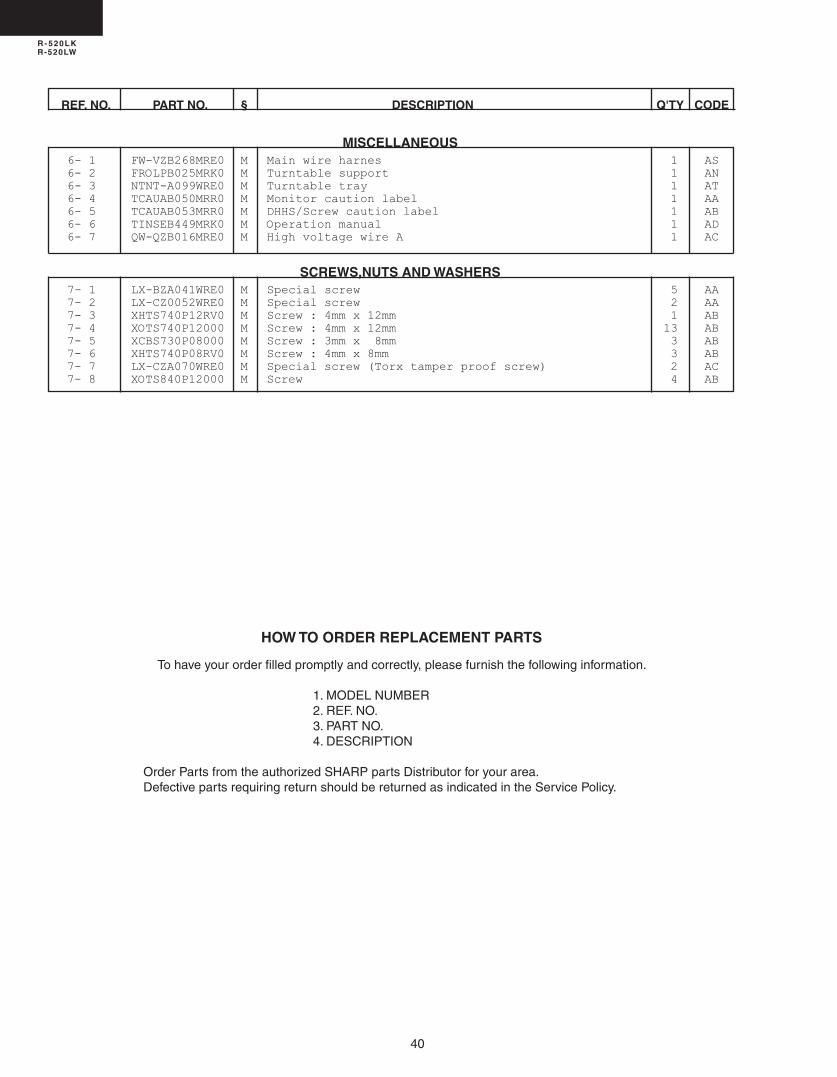
40
R - 520LKR-520LW
HOW TO ORDER REPLACEMENT PARTS
Tohaveyourorderfilledpromptlyandcorrectly,pleasefurnishthefollowinginformation.
1.MODELNUMBER.REF.NO.3.PARTNO.4.DESCRIPTION
OrderPartsfromtheauthorizedSHARPpartsDistributorforyourarea.DefectivepartsrequiringreturnshouldbereturnedasindicatedintheServicePolicy.
REF. NO. PART NO. § DESCRIPTION Q'TY CODE
MISCELLANEOUS6- 1 FW-VZB268MRE0 M Main wire harnes 1 AS6- 2 FROLPB025MRK0 M Turntable support 1 AN6- 3 NTNT-A099WRE0 M Turntable tray 1 AT6- 4 TCAUAB050MRR0 M Monitor caution label 1 AA6- 5 TCAUAB053MRR0 M DHHS/Screw caution label 1 AB6- 6 TINSEB449MRK0 M Operation manual 1 AD6- 7 QW-QZB016MRE0 M High voltage wire A 1 AC
SCREWS,NUTS AND WASHERS7- 1 LX-BZA041WRE0 M Special screw 5 AA7- 2 LX-CZ0052WRE0 M Special screw 2 AA7- 3 XHTS740P12RV0 M Screw : 4mm x 12mm 1 AB7- 4 XOTS740P12000 M Screw : 4mm x 12mm 13 AB7- 5 XCBS730P08000 M Screw : 3mm x 8mm 3 AB7- 6 XHTS740P08RV0 M Screw : 4mm x 8mm 3 AB7- 7 LX-CZA070WRE0 M Special screw (Torx tamper proof screw) 2 AC7- 8 XOTS840P12000 M Screw 4 AB

41
R - 520LKR-520LW
64 51 2 3
64 51 2 3
A
B
C
D
E
F
G
H
A
B
C
D
E
F
G
H
OVEN AND CABINET PARTS
2-3
4-7
6-5
1-4
4-6
4-8
4-9
6-3
6-22-1
7-5
1-9
4-10
7-2
7-2
7-4
4-3
1-10
1-7
7-3
7-6
7-5
7-6
4-2
7-4
1-8
7-11-6
1-6
4-47-1
4-1
1-1
1-2
2-2
2-2
2-2
2-2
7-4
7-4
4-11
7-4
6-4
1-11
7-4
7-7
7-4
7-7
1-5
1-3
4-5
7-4
7-4
1-13
4-12
1-12
1-5
4-13
7-5
7-21-14
7-8
7-8
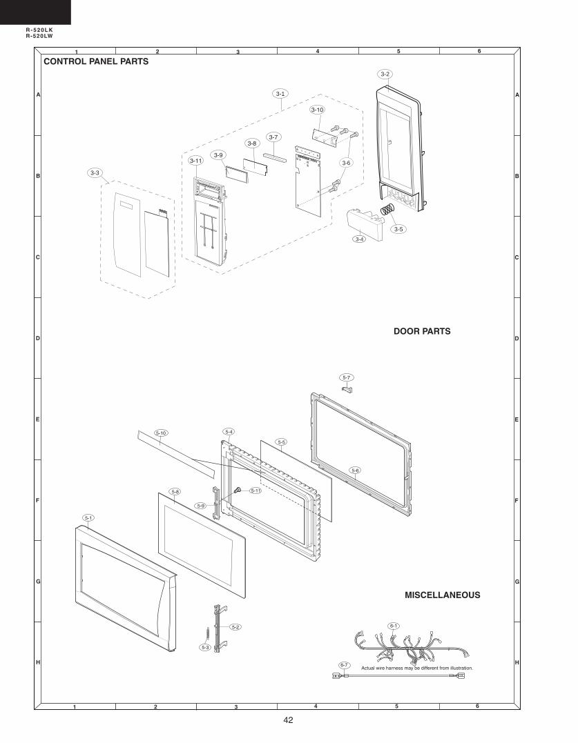
4
R - 520LKR-520LW
64 51 2 3
64 51 2 3
A
B
C
D
E
F
G
H
A
B
C
D
E
F
G
H
CONTROL PANEL PARTS
DOOR PARTS
MISCELLANEOUS
Actual wire harness may be different from illustration.6-7
6-1
5-5
5-6
5-4
5-9
5-2
5-11
5-1
5-3
5-8
5-10
5-7
3-8
3-9
3-3
3-6
3-10
3-7
3-4
3-2
3-5
3-11
3-1
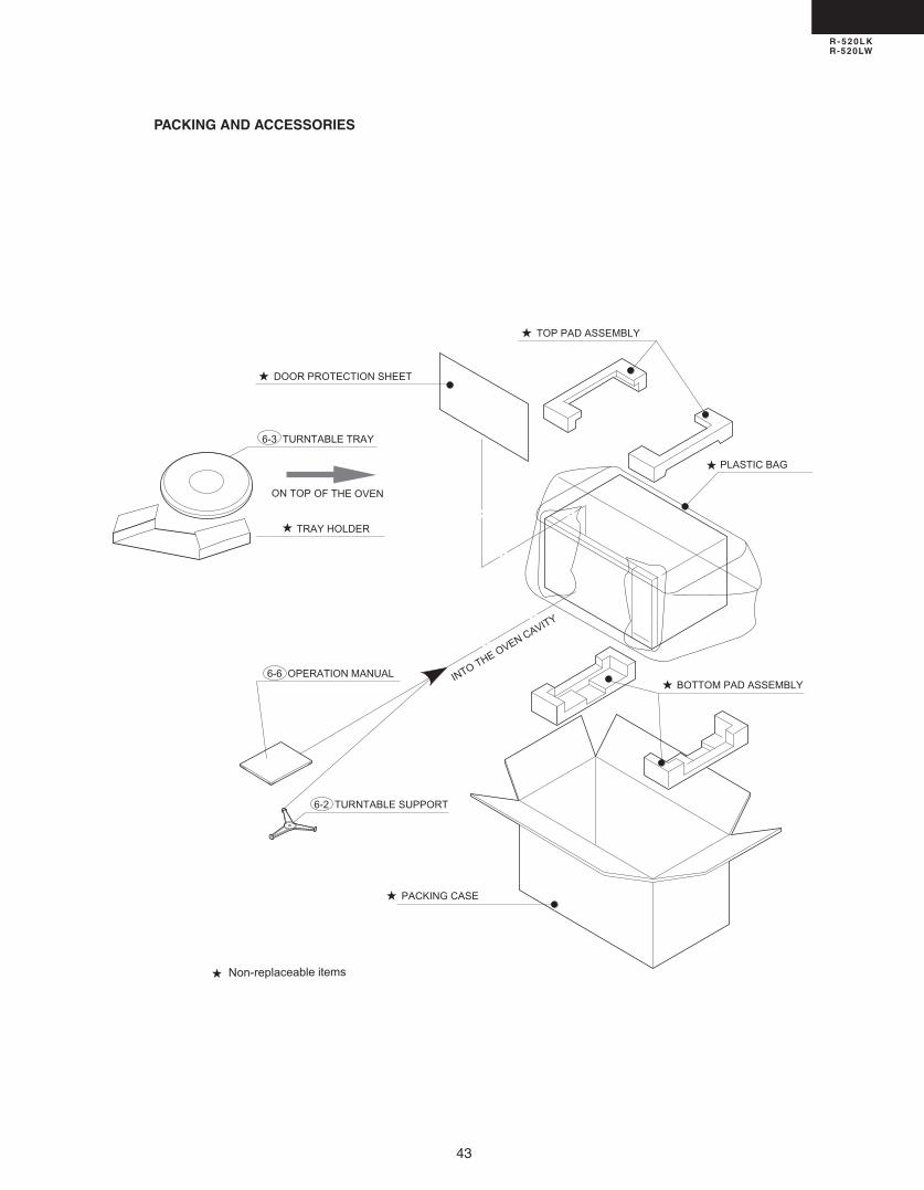
43
R - 520LKR-520LW
PACKING AND ACCESSORIES
DOOR PROTECTION SHEET
PLASTIC BAG
PACKING CASE
TOP PAD ASSEMBLY
INTO THE OVEN CAVITY
6-3 TURNTABLE TRAY
6-6 OPERATION MANUALBOTTOM PAD ASSEMBLY
TRAY HOLDER
6-2 TURNTABLE SUPPORT
ON TOP OF THE OVEN
Non-replaceable items

44
R - 520LKR-520LW
006SHARPCORP.(5M.00E)PrintedinU.S.A
COPYRIGHT©006BYSHARPCORPORATION
ALLRIGHTSRESERVED.
Nopartofthispublicationmaybereproduced,stored in retrieval systems, or transmittedin any form or by any means, electronic,mechanical, photocopying, recording, orotherwise,withoutpriorwrittenpermissionofthepublisher.