quickinstallationguide mic7000 ip67 connector kit en...mic7000 ip67 connector kit mic-ip67-5pk en...
TRANSCRIPT

MIC7000 IP67 Connector KitMIC-IP67-5PK
en Quick Installation Guide


MIC7000 IP67 Connector Kit Install a MIC7000 IP67 Connector Kit | en 3
Bosch Security Systems Quick Installation Guide 2016.07 | 1.2 | F.01U.291.526
1 Install a MIC7000 IP67 Connector KitThis kit protects the connections of as many as 5 MIC7000 cameras against dust or moisture,to an ingress rating of IP67. Required for MIC7000 cameras mounted directly to a surface(instead of to a MIC-DCA or to a MIC wall mount).
Parts List
Components for RJ45 connection
Qty Part
5 RJ45 couplers
10 RJ45 seal housings
10 RJ45 silicone seals
10 RJ45 end caps / nuts
Note: You may need to disassemble the assembly of the RJ45 connector before installation.
Components for Wire cables
Qty Part
50 Cable seals
25 Male terminals (used with Shroud housings)
25 Female terminals (used with Tower housings)

4 en | Install a MIC7000 IP67 Connector Kit MIC7000 IP67 Connector Kit
2016.07 | 1.2 | F.01U.291.526 Quick Installation Guide Bosch Security Systems
5 2-pin female (Shroud) Housings (for 24 VAC wires)
5 2-pin male (Tower) Housings (for 24 VAC wires)
5 3-pin female (Shroud) Housings (for RS-485 wires)
5 3-pin male (Tower) Housings (for RS-485 wires)
Additional Tools Required
1 Wire stripping tool suitable for wires 0.2 mm – 0.35 mm (AWG 28 – 22)
1 Wire crimping tool (such as the Weather Pack crimper from Delphi)
Optional Tools
1 Terminal extractor tool (such as the Weather Pack Terminal Extractor from Delphi)
1 Silicone sealant

MIC7000 IP67 Connector Kit Install a MIC7000 IP67 Connector Kit | en 5
Bosch Security Systems Quick Installation Guide 2016.07 | 1.2 | F.01U.291.526
Follow the installation steps in the MIC7000 Operation Manual until you are ready to make theelectrical connections, and then follow the steps here to complete installation. Note: Graphicsare not to scale.
Notice!Assemble connectors on all wires even if you plan to use only 24 VAC or only RS-485!Moisture could enter unsealed holes in the connector housings and void their ingress rating ofIP67.
1. Remove the five (5) quick-connect connectors from the ends of the cables at the base ofthe camera.

6 en | Install a MIC7000 IP67 Connector Kit MIC7000 IP67 Connector Kit
2016.07 | 1.2 | F.01U.291.526 Quick Installation Guide Bosch Security Systems
2. Slide one of each of the following pieces onto the RJ45 connector of the camera insequence: end cap / nut (item 4), silicone seal (item 3), seal housing (item 2).
3. Connect the RJ45 connector of the camera to the RJ45 coupler (item 1). Connect item 2 toitem 1. Slide item 3 into item 2. Connect item 4 to item 2.
MIC7000 IP67 Connector Kit Install a MIC7000 IP67 Connector Kit | en 7
Bosch Security Systems Quick Installation Guide 2016.07 | 1.2 | F.01U.291.526
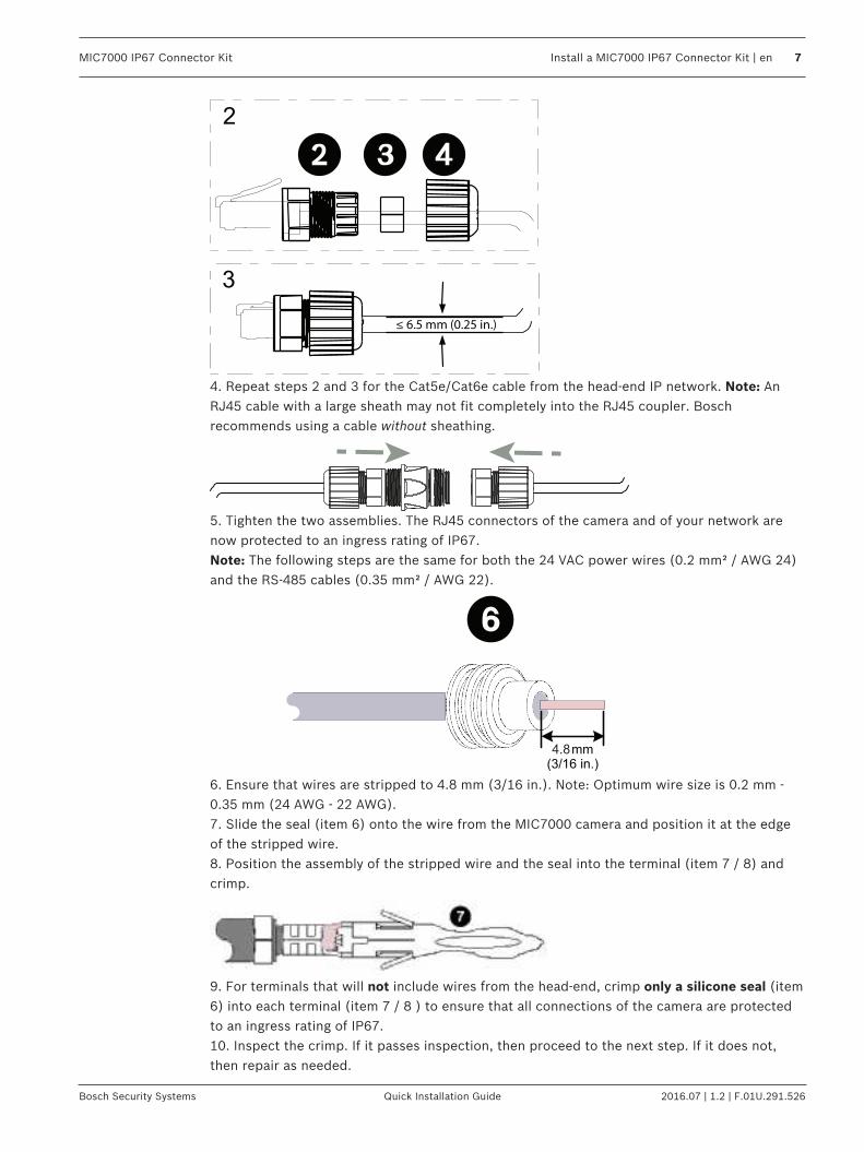
2
3
≤ 6.5 mm (0.25 in.)
4. Repeat steps 2 and 3 for the Cat5e/Cat6e cable from the head-end IP network. Note: AnRJ45 cable with a large sheath may not fit completely into the RJ45 coupler. Boschrecommends using a cable without sheathing.
5. Tighten the two assemblies. The RJ45 connectors of the camera and of your network arenow protected to an ingress rating of IP67.Note: The following steps are the same for both the 24 VAC power wires (0.2 mm² / AWG 24)and the RS-485 cables (0.35 mm² / AWG 22).
4.8mm (3/16 in.)
6. Ensure that wires are stripped to 4.8 mm (3/16 in.). Note: Optimum wire size is 0.2 mm -0.35 mm (24 AWG - 22 AWG).7. Slide the seal (item 6) onto the wire from the MIC7000 camera and position it at the edgeof the stripped wire.8. Position the assembly of the stripped wire and the seal into the terminal (item 7 / 8) andcrimp.
9. For terminals that will not include wires from the head-end, crimp only a silicone seal (item6) into each terminal (item 7 / 8 ) to ensure that all connections of the camera are protectedto an ingress rating of IP67.10. Inspect the crimp. If it passes inspection, then proceed to the next step. If it does not,then repair as needed.

8 en | Install a MIC7000 IP67 Connector Kit MIC7000 IP67 Connector Kit
2016.07 | 1.2 | F.01U.291.526 Quick Installation Guide Bosch Security Systems
11. Slide the group of crimped wires into the back of the housing (item 5 / 9, item 10 / 11).Note: When inserted properly, the terminal clicks into place; you cannot pull it out easily.Note: To remove the terminal at this point, you need a terminal extractor tool (user-supplied).Note: For housings without head-end wires, Bosch recommends that you apply a small amountof silicone sealant to the holes of the housing.12. Repeat steps 6 – 11 for all assemblies, for the connections from the camera and for thewires to the appropriate power supply and/or alarm connections.13. Close the covers of each housing.14. Connect the appropriate male housing to the female housing. The 24 VAC wires and theRS-485 wires of the camera and of your network are now protected to an ingress rating ofIP67.


Bosch Sicherheitssysteme GmbHRobert-Bosch-Ring 585630 GrasbrunnGermanywww.boschsecurity.com© Bosch Sicherheitssysteme GmbH, 2016
Bosch Security Systems, Inc1706 Hempstead RoadLancaster, PA, 17601USA