quick setup guide - audiocodes · pdf filequick setup guide 2. ... connect the e1/t1 trunk...
TRANSCRIPT

Version 6.8 / 7.0
May 2016
Quick Setup Guide BroadCloud SIP-Trunking Service using AudioCodes Mediant BRI/PRI Gateway
BRI/PRI Media Gateways
AudioCodes Mediant™ Series

BroadCloud SIP Trunk
AudioCodes Mediant BRI/PRI Gateway 2 Document #: LTRT-12393
Table of Contents 1 Introduction ......................................................................................................... 3
1.1 Component Information ............................................................................................ 3
2 Installing the Hardware ....................................................................................... 5
2.1 Mediant 500L Media Gateway ................................................................................. 5 2.2 Mediant 500 PRI Media Gateway .......................................................................... 10 2.3 Mediant 800B Media Gateway ............................................................................... 13
3 Connecting to the Management Interface ....................................................... 17
3.1 Default OAMP IP Address ...................................................................................... 17 3.2 Connecting to the Embedded Web Server ............................................................. 17
4 Configuring the Device ..................................................................................... 19
4.1 Step 1: Download, Install BroadCloud Certified Firmware / Configuration ............. 19 4.2 Step 2: Configure a Network Interface for the Device ............................................ 23 4.3 Step 3: Configure PSTN Trunk Settings ................................................................ 26 4.4 Step 4: Configure General SIP Parameters ........................................................... 28 4.5 Step 5: Configure Trunk Group Parameters .......................................................... 29 4.6 Step 6: Configure the Number of Digits to be Present to the PBX ......................... 32 4.7 Step 7: Check the SIP Trunk Registration Status .................................................. 34 4.8 Step 8: Secure Device Access ............................................................................... 35 4.9 Step 9: Save the Configuration, Connect to DMZ .................................................. 36
A Optional TDM PSTN Fallback if WAN Fails ..................................................... 37
B Troubleshooting ................................................................................................ 39
C AudioCodes ini File ........................................................................................... 41
Notice This Quick Setup Guide shows how to connect the BRI/PRI PBX and the BroadCloud SIP trunk using AudioCodes' Mediant Gateway product series. Information contained in this document is believed to be accurate and reliable at the time of printing. However, due to ongoing product improvements and revisions, AudioCodes cannot guarantee accuracy of printed material after the Date Published, nor can it accept responsibility for errors or omissions. Updates to this document and other documents as well as software files can be viewed by registered customers at http://www.audiocodes.com/downloads.
© Copyright 2016 AudioCodes Ltd. All rights reserved. This document is subject to change without notice.
Date Published: May-29-2016

Quick Setup Guide 1. Introduction
BroadCloud SIP Trunk 3 AudioCodes Mediant BRI/PRI Gateway
1 Introduction This guide shows how to set up AudioCodes' Mediant BRI/PRI Gateway to interoperate with the BroadCloud SIP trunk.
1.1 Component Information
1.1.1 AudioCodes Gateway Version Table 1-1: AudioCodes Gateway Version
SBC Vendor AudioCodes
Models Mediant 500L Mediant 500 Mediant 800B
Software Version Mediant 500L - SIP_F7.00A.044.007 Mediant 500 - SIP_F6.80A.263.005 Mediant 800B - SIP_F6.80A.263.005
Protocol SIP/UDP (to the BroadCloud SIP trunk) BRI/PRI (to the PSTN PBX)
1.1.2 BroadCloud SIP Trunking Version Table 1-2: BroadCloud Version
Vendor/Service Provider BroadSoft
SSW Model/Service BroadWorks
Software Version 21
Protocol SIP

BroadCloud SIP Trunk
AudioCodes Mediant BRI/PRI Gateway 4 Document #: LTRT-12393
1.1.3 Solution Topology Interoperability between AudioCodes' BRI/PRI gateway and the BroadCloud SIP trunk was achieved using the following topology setup: Enterprise BRI/PRI PBX AudioCodes Mediant Gateway device, connecting the enterprise’s BRI/PRI PBX to the
BroadCloud SIP trunking service over IP Internet/MPLS network connectivity to the BroadCloud SIP trunk service The figure below illustrates this solution topology:
Figure 1-1: Solution Configuration
Quick Setup Guide 2. Installing the Hardware
BroadCloud SIP Trunk 5 AudioCodes Mediant BRI/PRI Gateway
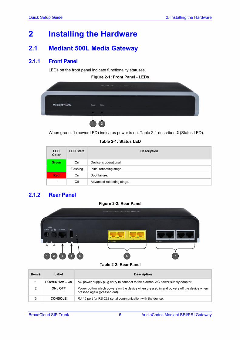
2 Installing the Hardware 2.1 Mediant 500L Media Gateway
2.1.1 Front Panel LEDs on the front panel indicate functionality statuses.
Figure 2-1: Front Panel - LEDs
When green, 1 (power LED) indicates power is on. Table 2-1 describes 2 (Status LED).
Table 2-1: Status LED
LED Color
LED State Description
Green On Device is operational.
Flashing Initial rebooting stage.
Red On Boot failure.
- Off Advanced rebooting stage.
2.1.2 Rear Panel Figure 2-2: Rear Panel
Table 2-2: Rear Panel
Item # Label Description
1 POWER 12V -- 3A AC power supply plug entry to connect to the external AC power supply adapter.
2 ON / OFF Power button which powers on the device when pressed in and powers off the device when pressed again (pressed out).
3 CONSOLE RJ-45 port for RS-232 serial communication with the device.

BroadCloud SIP Trunk
AudioCodes Mediant BRI/PRI Gateway 6 Document #: LTRT-12393
Item # Label Description
4
USB 2.0 port, not applicable.
5 // Reset pinhole button to reset the device or to restore to factory defaults. To restore to factory defaults: With a paper clip or any other similar pointed object, press and hold down the pinhole button for at least 12 seconds, but no longer than 25 seconds
6 S1 / FE LAN Up to four Fast Ethernet (10/100Base-T) ports (RJ-45) to connect to LAN or WAN. These support full-duplex modes, auto-negotiation, and straight or crossover cable detection.
7 S2 / BRI Up to four ISDN BRI port interfaces (RJ-45)
2.1.3 Cabling
2.1.3.1 Connecting LAN Interfaces Four Fast Ethernet (10/100Base-T) ports (supporting half- and full-duplex modes, auto-negotiation, and straight or crossover cable detection) allow connection to the LAN/WAN.
To connect the device to the BroadCloud service:
1. If the device's IP isn't configured yet, connect as shown in Section 3. 2. If the device's IP has already been configured:
a. Connect one end of a straight-through RJ-45 Cat 5e or Cat 6 cable to the RJ-45 port labeled S1 / FE LAN port 1.
b. Connect the other end to the DMZ port assigned by the IT administrator.
Figure 2-3: Cabling Ethernet Ports
2.1.3.2 Connecting BRI Lines This section shows how to connect the device's BRI ports to the PBX.
Warning: To protect against electrical shock and fire, use a 26 AWG min wire.
To connect a BRI line:
1. Connect the RJ-45 cable to the device's BRI port 1 on the rear panel (it's labeled S2 / BRI).

Quick Setup Guide 2. Installing the Hardware
BroadCloud SIP Trunk 7 AudioCodes Mediant BRI/PRI Gateway
Figure 2-4: Cabling BRI Ports
2. Connect the other end of the cable to your ISDN PBX equipment.
2.1.3.3 Connecting to the Power Supply The device is powered by an external 12V AC/DC power adapter (supplied), connected to a standard alternating current (AC) electrical wall outlet.
Table 2-3: Power Specifications
Item Description
Power Supply Single universal external AC power supply
Input Ratings 100-240 VAC, 50-60 Hz
Output Ratings 12V/3A
Warning: Use only the AC/DC power adapter supplied with the device.
The device is shipped with the AC/DC power adapter shown Figure 2-5 which also supports interchangeable plugs to suite the electrical wall outlet type requirement of the country in which the device is being installed.

BroadCloud SIP Trunk
AudioCodes Mediant BRI/PRI Gateway 8 Document #: LTRT-12393
Figure 2-5: AC/DC Power Adapter
Table 2-4: Power Adapter with Interchangeable Plugs
Item Description
1 Plug slot
2 Plug lock
3 Plug release lever
4 DC power cord
5 DC power plug
To connect the device to the power supply using the power adapter:
1. Insert the relevant AC plug into the housing power adapter: a. Insert the top part of the plug into the upper part of the housing slot (1). b. Press down on the bottom part of the plug until a "click" sound is heard, indicating
that the plug is securely inserted in the housing slot. To remove the plug, push and slide down the OPEN plug release lever (3).
Figure 2-6: Inserting Plug into Power Adapter
2. Insert the DC plug (5) located at the end of the power cord (4) of the power adapter
into the device's power socket located on the rear panel.

Quick Setup Guide 2. Installing the Hardware
BroadCloud SIP Trunk 9 AudioCodes Mediant BRI/PRI Gateway
Figure 2-7: Cabling to Power using Power Adapter
3. Plug the power adapter directly into a standard electrical wall outlet.
2.1.4 Powering the Device On / Off The power switch is located on its rear panel (see Section 2.1.2).
To power on the device:
Press in the power button; the device receives power, indicated by the lighting of the Power LED on the front panel.
To power off the device: Press out the power button; the device powers off, indicated by the Power LED going
off.

BroadCloud SIP Trunk
AudioCodes Mediant BRI/PRI Gateway 10 Document #: LTRT-12393
2.2 Mediant 500 PRI Media Gateway Figure 2-8: Front Panel - Ports
Table 2-5: Front Panel
Item # Label Description
1 POWER / STATUS LEDs indicating the status of the power and reboot/initialization.
2 // Reset pinhole button to reset and optionally to restore to factory defaults. To restore to factory defaults: Press and hold down the pinhole button for at least 12 seconds, but no longer than 25 seconds, with a paper clip or any other similar pointed object.
3 CONSOLE RJ-45 port for RS-232 serial communication
4 LAN Up to four Gigabit Ethernet (10/100/1000Base-T) ports to connect to LAN (IP phones, computers, or switches). These ports support half- and full-duplex modes, auto-negotiation, and straight or crossover cable detection.
5 PRI Single E1/T1 port interface (RJ-48).
6 USB Two USB 2.0 ports. Do not use.
Figure 2-9: Rear Panel – Earth and Power
Table 2-6: Rear Panel
Item # Label Description
1
Protective earthing screw.
2 I / 0 Power switch (O is off; I is on).
3 100-240V~50-60Hz 0.8A Max. Three-prong AC power supply entry.
2.2.1 Cabling
2.2.1.1 Grounding the Device The device must be connected to earth (grounded) using an equipment-earthing conductor.

Quick Setup Guide 2. Installing the Hardware
BroadCloud SIP Trunk 11 AudioCodes Mediant BRI/PRI Gateway
Protective Earthing The equipment is classified as Class I EN60950 and UL60950 and must be earthed at all times. For Finland: "Laite on liltettava suojamaadoituskoskettimilla varustettuun pistorasiaan." For Norway: "Apparatet rna tilkoples jordet stikkontakt." For Sweden: "Apparaten skall anslutas till jordat uttag."
To earth the device:
1. Connect an electrically earthed strap of 16 AWG wire (minimum) to the chassis' earthing screw (located on the rear panel), using the supplied washer.
2. Connect the other end of the strap to a protective earthing. This should be in accordance with the regulations enforced in the country of installation.
Figure 2-10: Earthing the Device
2.2.1.2 Connecting to the LAN Up to 4 Gigabit Ethernet (10/100/1000Base-T) ports supporting half- and full-duplex mode, auto-negotiation, and straight/crossover cable detection allow connection to LAN/WAN.
To connect the device to the BroadCloud service:: 1. If the device's IP isn't configured yet, connect as shown in Section 3. 2. If the device's IP has already been configured:
a. Connect one end of a straight-through RJ-45 Cat 5e or Cat 6 cable to the RJ-45 port labeled S1 / LAN GE port 1.
b. Connect the other end to the DMZ port assigned by the IT administrator.
Figure 2-11: Cabling the Ethernet Ports
3. Connect the other end of the cable to the Gigabit Ethernet network.
2.2.1.3 Connecting to an ISDN PRI (E1/T1) Trunk This section shows how to cable the device's E1/T1 (PRI) trunk interface.

BroadCloud SIP Trunk
AudioCodes Mediant BRI/PRI Gateway 12 Document #: LTRT-12393
Warning: To protect against electrical shock and fire, use a 26 AWG min wire to connect the E1 / T1 port to the PSTN.
To connect the E1/T1 trunk interface: 1. Connect the E1/T1 trunk cable to the device’s E1/T1 port. 2. Connect the other end of the trunk cable to your PBX switch.
Figure 2-12: Cabling E1/T1 Port
2.2.1.4 Connecting to the Power Supply The device receives power from a standard alternating current (AC) electrical outlet. The connection is made using the supplied AC power cord.
Table 2-7: Power Specifications
Physical Specification Value
Input Voltage Single universal AC power supply 100 to 240V
AC Input Frequency 50 to 60 Hz
AC Input Current 0.8A
Warnings: The device must be connected to a socket-outlet providing a protective earthing connection. Use only the AC power cord that is supplied with the device.
To connect the device to the power supply:
1. Connect the line socket of the AC power cord (supplied) to the device's AC power socket (labeled 100-240V~50-60 Hz 0.8A), located on the rear panel.
Figure 2-13: Connecting to the Power Supply
2. Connect the plug at the other end of the AC power cord to a standard electrical outlet. 3. Press the power switch to on (I) position so that the device receives power; the
POWER LED on the front panel is lit green.

Quick Setup Guide 2. Installing the Hardware
BroadCloud SIP Trunk 13 AudioCodes Mediant BRI/PRI Gateway
2.3 Mediant 800B Media Gateway
2.3.1 Front Panel Figure 2-14: Front Panel
Table 2-8: Front Panel Description
Item # Label Description
1 USB/WWAN N/A
2 RS-232 RS-232 port for serial communication. Cable not included.
3 POWER/STATUS LEDs indicating power and reboot/initialization status. See also Section 2.3.2 on page 13.
4 BRI / Digital Telephony port interfaces
5 - Reset pinhole button to reset and optionally to restore factory defaults. To restore to factory defaults: Press and hold down the Reset pinhole button with a paper clip or similar pointed object, for at least 12 seconds but no more than 25.
6 GE Four 10/100/1000Base-T (Gigabit Ethernet) LAN/WAN ports.
7 FE N/A
2.3.2 Front Panel LEDs
2.3.2.1 E1/T1 LEDs Each trunk port provides a LED indicating operating status:
Table 2-9: E1/T1 LEDs
Color State Description
Green On Trunk is synchronized (normal operation).
Red On Loss due to any of the following signals: LOS - Loss of Signal LOF - Loss of Frame AIS - Alarm Indication Signal (the Blue Alarm) RAI - Remote Alarm Indication (the Yellow Alarm)
- Off Failure / disruption in the AC power supply or the power is currently not being supplied to the device through the AC power supply entry.
2.3.2.2 Operational Status LEDs The STATUS LED indicates the operating status.

BroadCloud SIP Trunk
AudioCodes Mediant BRI/PRI Gateway 14 Document #: LTRT-12393
Table 2-10: STATUS LEDs
LED Color LED State Description
Green On The device is operational and in Standalone mode (not in High-Availability mode).
Flashing Initial rebooting stage.
Slow Flash HA mode - LED on Active device.
Slow-Fast Flash
HA mode - LED on Redundant device.
Red On Boot failure.
Off Advanced rebooting stage.
2.3.3 Rear Panel Figure 2-15: Rear Panel
Table 2-11: Rear Panel
Item # Label Description
1
Protective earthing screw.
2 100-240V~1.5A 50-60Hz
3-Prong AC power supply entry.
2.3.4 Cabling
2.3.4.1 Grounding the Device The device must be connected to earth (grounded) using an equipment-earthing conductor.
Protective Earthing The equipment is classified as Class I EN60950 and UL60950 and must be earthed at all times. For Finland: "Laite on liltettava suojamaadoituskoskettimilla varustettuun pistorasiaan." For Norway: "Apparatet rna tilkoples jordet stikkontakt." For Sweden: "Apparaten skall anslutas till jordat uttag."
To ground the device:
1. Connect an electrically earthed strap of 16 AWG wire (minimum) to the chassis' grounding screw (located on the rear panel), using the supplied washer.

Quick Setup Guide 2. Installing the Hardware
BroadCloud SIP Trunk 15 AudioCodes Mediant BRI/PRI Gateway
Figure 2-16: Grounding the Device
2. Connect the other end to a protective earthing (according local regulations).
2.3.4.2 Connecting to Ethernet Up to four 10/100/1000Base-T (Gigabit Ethernet) RJ-45 ports supporting half- and full-duplex modes, auto-negotiation, and straight or crossover cable detection, allow connecting to the LAN/WAN.
To connect the device to the BroadCloud service:
1. If the device's IP isn't configured yet, connect as shown in Section 3. 2. If the device's IP has already been configured:
a. Connect one end of a straight-through RJ-45 Cat 5e or Cat 6 cable to the RJ-45 port labeled LAN GE port 1.
b. Connect the other end to the DMZ port assigned by the IT administrator.
Figure 2-17: Connecting the LAN Ports
2.3.4.2.1 Connecting to ISDN PRI (E1/T1) Trunks
Warning: To protect against electrical shock and fire, use a 26 AWG min wire to connect T1 or E1 ports to the PSTN.
To connect the E1/T1 trunk interface:
1. Connect the E1/T1 trunk cable(s) to the device’s E1/T1 port. 2. Connect the other end of the trunk cable to your PBX switch.

BroadCloud SIP Trunk
AudioCodes Mediant BRI/PRI Gateway 16 Document #: LTRT-12393
Figure 2-18: Cabling E1/T1 Ports
2.3.5 Powering up The device receives power from a standard alternating current (AC) electrical outlet. The connection is made using the supplied AC power cord.
Table 2-12: Power Specifications
Physical Specification Value
Input Voltage Single universal AC power supply 100 to 240V
AC Input Frequency 50 to 60 Hz
AC Input Current 1.5A
Warning:
• The device must be connected to a socket-outlet providing protective earthing. • Use only the AC power cord that is supplied with the device.
To connect the device to the power supply:
1. Connect the line socket of the AC power cord (supplied) to the device's AC power socket (labeled 100-240V 1.5A ~50-60 Hz), located on the rear panel.
Figure 2-19: Connecting to the Power Supply
2. Connect the plug at the other end of the AC power cord to a standard electrical outlet. After cabling and powering up, the POWER LED on the front panel lights up green.

Quick Setup Guide 3. Connecting to the Management Interface
BroadCloud SIP Trunk 17 AudioCodes Mediant BRI/PRI Gateway
3 Connecting to the Management Interface This section shows how to connect to the device's management interface for the first time.
3.1 Default OAMP IP Address The device is shipped with a factory default IP address for operations, administration, maintenance, and provisioning (OAMP), through its VoIP LAN interface. Use this address to initially access the device's embedded Web server. Default IP address is:
Table 3-1: Default VoIP LAN IP Address for OAMP
IP Address Value
IP Address 192.168.0.2
Prefix Length 255.255.255.0 (24)
Default Gateway 192.168.0.1
3.2 Connecting to the Embedded Web Server To connect to the embedded Web server: 1. Connect Port 1 (leftmost LAN port) located on the front panel directly to the network
interface of your computer, using a straight-through Ethernet cable.
Figure 3-1: Connecting to the Embedded Web Server
BroadCloud SIP Trunk
AudioCodes Mediant BRI/PRI Gateway 18 Document #: LTRT-12393
2. Change the IP address and subnet mask of your computer to correspond with the default OAMP IP address and subnet mask of the device.
3. Access the Web interface: a. On your computer, start a Web browser and in the URL address field, enter the
default IP address of the device; the Web interface's Web Login screen appears:
Figure 3-2: Web Login Screen
b. In the 'Username' and 'Password' fields, enter the case-sensitive, default login
username (Admin) and password (Admin). c. Click Login.
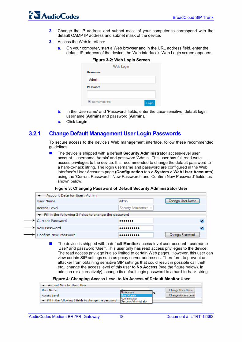
3.2.1 Change Default Management User Login Passwords To secure access to the device's Web management interface, follow these recommended guidelines: The device is shipped with a default Security Administrator access-level user
account – username 'Admin' and password 'Admin'. This user has full read-write access privileges to the device. It is recommended to change the default password to a hard-to-hack string. The login username and password are configured in the Web interface's User Accounts page (Configuration tab > System > Web User Accounts) using the 'Current Password', 'New Password', and 'Confirm New Password' fields, as shown below:
Figure 3: Changing Password of Default Security Administrator User
The device is shipped with a default Monitor access-level user account - username
'User' and password 'User'. This user only has read access privileges to the device. The read access privilege is also limited to certain Web pages. However, this user can view certain SIP settings such as proxy server addresses. Therefore, to prevent an attacker from obtaining sensitive SIP settings that could result in possible call theft etc., change the access level of this user to No Access (see the figure below). In addition (or alternatively), change its default login password to a hard-to-hack string.
Figure 4: Changing Access Level to No Access of Default Monitor User

Quick Setup Guide 4. Configuring the Device
BroadCloud SIP Trunk 19 AudioCodes Mediant BRI/PRI Gateway
4 Configuring the Device This section shows how to configure the device to interwork with the BroadCloud SIP trunk, based on the solution test topology shown in Section 1.1.3 which includes these areas: BroadCloud WAN interface - BroadCloud SIP trunking environment BroadCloud TDM interface - BRI or PRI PBX Configuration is performed using the device's embedded Web server (Web interface).
4.1 Step 1: Download, Install BroadCloud Certified Firmware / Configuration This section shows how to download the certified BroadCloud firmware and configuration.
To download the certified BroadCloud firmware and configuration:
1. Open a web browser, go to http://www.audiocodes.com/broadcloud-resource-center 2. Download the zip file associated with your device, unzip the package, and save the
enclosed configuration_xxxx.ini file and firmware_xxx.cmp file to your local drive. 3. Download the Call Progress Tones file suitable for your country –
call_progress_xxxxx.dat (‘xxxxx’ being the country name). 4. Enter the device's Software Upgrade Wizard.
To load files using the Software Upgrade Wizard: 1. Open the Software Upgrade Wizard:
• Select the Maintenance tab, click the Software Update menu, and then click Software Upgrade Wizard -or-
• On the toolbar, click Device Actions and then choose Software Upgrade Wizard.
Figure 4-1: Start Software Upgrade Wizard Screen
2. Click Start Software Upgrade; the wizard starts, prompting you to load a .cmp file:

BroadCloud SIP Trunk
AudioCodes Mediant BRI/PRI Gateway 20 Document #: LTRT-12393
Figure 4-2: Software Upgrade Wizard - Load CMP File
Note: At this stage, you can quit the wizard without needing to reset the device(click Cancel ). But if you continue with the wizard and load the cmp file, the upgrade process must be completed with a device reset.
3. Click Browse, and then navigate to where the .cmp file is located on your computer.
Select the file, and then click Open. 4. Click Load File; the device installs the .cmp file. A progress bar displays the loading
process status and a message informs you when file load successfully completes.
Figure 4-3: Software Upgrade Wizard – CMP File Loading Progress Bar
5. Select the following upgrade option:
• System Reset Upgrade

Quick Setup Guide 4. Configuring the Device
BroadCloud SIP Trunk 21 AudioCodes Mediant BRI/PRI Gateway
6. Press the Next button to navigate through the wizard. 7. In the wizard page for loading an ini file:
• Deselect the 'Use existing configuration' option • Load a new ini file: In the 'Load an ini file...' field, click Browse, and then
navigate to where the ini file is located on your computer. Select the file, and then click Load File; the device loads the ini file.
Figure 4-4: Software Upgrade Wizard – Load INI File
8. Press the Next button to navigate to the Call Progress Tones (CPT) wizard page.
9. In the wizard page for loading the Call Progress Tones (CPT) file, click Browse, and then navigate to where the call_progress_xxxxx.dat (‘xxxxx’ being the country name) file is located on your computer. Select it and click Load File; the device loads the tones file.
Figure 4-5: Software Upgrade Wizard – Loading the CPT File
10. Click Next until the last wizard page appears (the FINISH button is highlighted in the left pane):

BroadCloud SIP Trunk
AudioCodes Mediant BRI/PRI Gateway 22 Document #: LTRT-12393
Figure 4-6: Software Upgrade Wizard – Files Loaded
11. Click Reset to burn the files to the device's flash memory; the 'Burn and reset in progress' message is displayed and the device 'burns' the newly loaded files to flash memory and then resets.
Note: Reset may take a few minutes (even up to 30) depending on .cmp file version.
When the device finishes the installation process and resets, the following wizard page is displayed, showing the installed software version and other files (ini file and auxiliary files) that you may also have installed:
Figure 4-7: Software Upgrade Process Completed Successfully
12. Click End Process to close the wizard; Web Login is displayed. 13. Enter your login username and password (Admin, Admin respectively), and then click
Login; a message box appears informing you of the new .cmp file version. 14. Click OK; the Web interface becomes active, reflecting the upgraded device.

Quick Setup Guide 4. Configuring the Device
BroadCloud SIP Trunk 23 AudioCodes Mediant BRI/PRI Gateway
4.2 Step 2: Configure a Network Interface for the Device This section describes typical physical Ethernet port connections of the deployed device. There are two methods to connect the device to the DMZ: 1. Method A: [Preferred method] With a ‘Global IP Address’ provided to the gateway
device, without a NAT. The firewall is configured with the following rules (for example):
a. FW allow rule:
Original
Source Destination Ports/Service
1 <any> (e.g. ITSP)
Global IP Address (public address)
SIP service: 5060 / UDP RTP service: 6000-7000 / UDP
b. Method B: With a ‘local-DMZ-IP Address’ behind a NAT. The firewall is configured with the following rules (for example):
c. Firewall allow rule:
Original Translated
Source Destination Ports/Service Source Destination Ports/Service
1 <any> (e.g. ITSP)
Global IP Address (public address)
SIP service: 5060 / UDP RTP service: 6000-7000 / UDP
<any> (e.g. ITSP)
Local-DMZ-IP-Address
<as original>
d. NAT rules (port forwarding): Source Destination Ports/Service Source Destination Ports/Service
1 <any> (e.g. ITSP)
Global IP Address (public address)
SIP service: 5060 / UDP RTP service: 6000-7000 / UDP
<any> (e.g. ITSP)
Local-DMZ-IP-Address
<as original>
1 Local-DMZ-IP-Address
<any> (e.g. ITSP)
SIP service: 5060 / UDP RTP service: 6000-7000 / UDP
Global IP Address (public address)
<any> (e.g. ITSP)
<as original>

BroadCloud SIP Trunk
AudioCodes Mediant BRI/PRI Gateway 24 Document #: LTRT-12393
4.2.1 Step 2a: Configure the Local DMZ IP Address of the Gateway To configure the IP network interface:
1. Open the IP Interfaces Table page (Configuration tab > VoIP menu > Network > IP Interfaces Table).
2. Modify the existing network interface: a. Select the 'Index' radio button of the OAMP + Media + Control table row, and
then click Edit. b. Configure the interface as follows:
Parameter Value
IP Address If working in Method A: Local-DMZ-IP-Address (public address) If working in Method B: Local-DMZ-IP-Address
Prefix Length Subnet mask in bits
Gateway Default Gateway
Interface Name "Voice" (arbitrary descriptive name)
Primary DNS Server IP Address IP address of the DNS Server
Underlying Device vlan 1
3. Click Submit.
Note: The change only takes effect after you save your settings by resetting the device with a flash burn. This only occurs at the end of the configuration process.
The figure below shows an example of a configured IP network interface.
Figure 4-8: Example of a Configured Network Interface in IP Interfaces Table

Quick Setup Guide 4. Configuring the Device
BroadCloud SIP Trunk 25 AudioCodes Mediant BRI/PRI Gateway
4.2.2 Step 2b: Configure NAT Only applies if connecting according to Method B (described above).
Note: Do not configure this setting if you are not behind a firewall NAT.
Note: The ‘NAT IP Address’ is the Global-IP-address used in front of the firewall facing the BroadCloud service. If the DMZ holds the global-IP-address (no NAT is performed by the firewall) and the gateway is already assigned with the global-IP-address as its ‘local DMZ IP address’, skip NAT configuration.
Define NAT address on the gateway device: 1. Open the SIP General Parameters page (Configuration tab > VoIP menu > SIP
Definitions > General Parameters).
Figure 4-9: SIP General Parameters
2. In the 'NAT IP Address' field, enter the NAT IP address in dotted-decimal notation. 3. Click Submit.

BroadCloud SIP Trunk
AudioCodes Mediant BRI/PRI Gateway 26 Document #: LTRT-12393
4.3 Step 3: Configure PSTN Trunk Settings This step shows how to configure PSTN trunk settings.
4.3.1 Step 3a: Configure the BRI PSTN Interface This step shows how to configure the BRI PSTN Interface. Skip to the next step if you have a PRI interface.
To configure the BRI PSTN interface:
1. Open the Trunk Settings page (Configuration tab > VoIP > PSTN > Trunk Settings). 2. Configure following parameters:
Parameter Value
Protocol Type BRI EURO ISDN
ISDN Termination Side Network side (for BRI PBX connection) or User side (for PSTN Fallback connection)
BRI Layer2 Mode Point To Multipoint
Q931 Layer Response Behavior 0x8000000
Outgoing Calls Behavior 0x0
Incoming Calls Behavior 0x11000
Select Receiving of Overlap Dialing Local Receiving
Figure 4-10: Configuring BRI PSTN Interface
3. Repeat for all BRI ports available on the device (Mediant 500L)

Quick Setup Guide 4. Configuring the Device
BroadCloud SIP Trunk 27 AudioCodes Mediant BRI/PRI Gateway
4.3.2 Step 3b: Configure the PRI PSTN Interface This step shows how to configure the PRI PSTN Interface.
To configure the PRI PSTN interface: 1. Open the Trunk Settings page (Configuration tab > VoIP menu > PSTN > Trunk
Settings). 2. Configure following parameters:
Parameter Value
Protocol Type E1 EURO ISDN
Clock Master Generated (The device is clock master) Recovered (The device slaves from the line clock)
Framing Method E1 Framing MFF CRC4 Ext (according to remote side, PBX or PSTN, definitions)
ISDN Termination Side Network side or User side
Figure 4-11: Configuring the PRI PSTN Interface
3. Repeat for PRI trunk #2 if applicable (Mediant 800B)

BroadCloud SIP Trunk
AudioCodes Mediant BRI/PRI Gateway 28 Document #: LTRT-12393
4.4 Step 4: Configure General SIP Parameters This step identifies the device configuration needed to support the SIP General Parameters configuration.
4.4.1 Step 4a: Configure Registration Parameters This step shows how to configure the SIP Proxy and Registration parameters, including configuring a Proxy Name, Registrar Name, DNS query for the BroadCloud Proxy Set, Registration and Subscription modes.
To configure the SIP Proxy & Registration parameters:
1. Open the SIP Proxy & Registration Parameters page (Configuration tab > VoIP > SIP Definitions > Proxy & Registration).
Figure 4-12: Configuring Proxy & Registration Parameters
2. From the 'Use Default Proxy' dropdown, select Yes. 3. For ‘Proxy Name’, enter the domain name that can be found on the BroadCloud
MySite Trunk Group configuration page, under the section 'Trunk Group Settings'. 4. From the 'Enable Fallback to Routing Table' dropdown, select Enable (when PSTN
Fallback is implemented on the Mediant Gateway). 5. From the 'Always Use Proxy' dropdown, select Enable. 6. For ‘Registrar Name’, enter the domain name that can be found on the BroadCloud
MySite Trunk Group configuration page, under the section 'Trunk Group Settings'. 7. From the 'DNS Query Type' dropdown, select SRV. 8. From the 'Proxy DNS Query Type' dropdown, select SRV. 9. From the 'Subscription Mode' dropdown, select Per Gateway. 10. In the 'User Name' field, configure Trunk Group Pilot User. 11. In the 'Password' field, configure Trunk Group Pilot User Password. 12. From the 'Registration Mode' dropdown, select Per Gateway. 13. Click Submit.

Quick Setup Guide 4. Configuring the Device
BroadCloud SIP Trunk 29 AudioCodes Mediant BRI/PRI Gateway
4.5 Step 5: Configure Trunk Group Parameters
Note: This configuration is by default correct and should only be verified.
This step shows how to configure the the device's channels, which includes assigning them to Trunk Groups. A Trunk Group is a logical group of physical trunks and channels. A Trunk Group can include multiple trunks and ranges of channels. To enable and activate the device's channels, Trunk Groups must be configured. Channels not configured in this table are disabled. After configuring Trunk Groups, use them to route incoming IP calls to the Tel side, represented by a specific Trunk Group (ID). You can also use Trunk Groups for routing Tel calls to the IP side.
4.5.1 Step 5a: Configure the BRI Trunk Group (for Devices with BRI) This section shows how to configure the BRI Trunk Group. If your device does not have BRI, skip this step.
To configure the BRI Trunk Group Table:
1. Open the Trunk Group Table page (Configuration tab > VoIP > GW and IP to IP > Trunk Group > Trunk Group).
Figure 4-13: Configuring BRI Trunk Group Table
2. Configure each Trunk Group as required. If more than one BRI port is available, on
line 1 of the table above, set “To Trunk” to the last BRI port to be used for incoming / outgoing calls between BroadCloud service and the PBX. See below Info box on what line 2 is used for.
Note: In the figure above, Trunk Group 1 is used for calls to/from BroadCloud service, Trunk Group 4 is used to define an extra TDM BRI port for PSTN fallback should BroadCloud service become unreachable for any reason. The example above sets BRI port 2 to be used with PSTN fallback Trunk Group 4. See the appendix for more information on how to configure PSTN fallback. If PSTN fallback is not used, the Trunk Group 4 setting can be discarded.

BroadCloud SIP Trunk
AudioCodes Mediant BRI/PRI Gateway 30 Document #: LTRT-12393
4.5.2 Step 5b: Configure the PRI Trunk Group (for Devices with PRI) This section shows how to configure the PRI Trunk Group. If your device does not have PRI, skip this step.
To configure the PRI Trunk Group Table: 1. Open the Trunk Group Table page (Configuration tab > VoIP > GW and IP to IP >
Trunk Group > Trunk Group).
Figure 4-14: Configuring PRI Trunk Group Table
2. Configure each Trunk Group as required. If more than one PRI port is available, on line 1 of the table above, set 'To Trunk' to the last PRI port (2) to be used for incoming / outgoing calls between BroadCloud service and the PBX.
Note: In the figure above, Trunk Group 1 is used for calls to/from BroadCloud service, Trunk Group 4 is used to define an extra TDM PRI port for PSTN fallback should BroadCloud service become unreachable. The example above sets PRI port 2 to be used with PSTN fallback Trunk Group 4. See the appendix for how to configure PSTN fallback. If PSTN fallback is not used, the Trunk Group 4 setting can be discarded.
4.5.3 Step 5c: Configure Trunk Group Settings The Trunk Group Settings page allows you to configure the following per trunk group: Channel Select Mode by which IP-to-Tel calls are assigned to the Trunk Group's
channels Registration Mode for registering Trunk Groups
To configure the Trunk Group Settings:
1. Open the Trunk Group Table page (Configuration tab > VoIP > GW and IP to IP > Trunk Group > Trunk Group Settings).

Quick Setup Guide 4. Configuring the Device
BroadCloud SIP Trunk 31 AudioCodes Mediant BRI/PRI Gateway
Figure 4-15: Configuring Trunk Group Settings
2. For each Trunk Group ID, from the 'Channel Select Mode' dropdown, select Cyclic
Ascending. 3. Click Submit to apply your changes.
4.5.4 Step 5d: Configure Inbound IP Routing This section shows configuring Mediant BRI/PRI Gateway Inbound (IP-to-Tel) Routing. When having more than one TDM interface (more than one BRI or PRI), you can choose to route calls based on incoming IP SIP call message to a specific TDM port i.e., Trunk Group.
To configure IP-to-Tel or Inbound IP Routing Rules:
1. Open the Outbound IP Routing Table page (Configuration tab > VoIP > GW and IP to IP > Routing > IP to Trunk Group Routing).
Figure 4-16: Configuring Inbound IP Routing Rules
2. Configure a rule for all incoming IP calls, with the destination prefix assigned to a
specific PBX (e.g. 832), route them to Trunk Group ID 1 (connected to the PBX). 3. (Optional) When using PSTN fallback, configure another rule for a Fallback scenario:
all incoming PSTN calls, route them to Trunk Group ID 4 (connected to the PSTN Fallback Trunk).
4. Click Submit to apply definitions.
Note: In the configuration above, Trunk Group 1 is used for calls to/from BroadCloud service, Trunk Group 4 is used to define an extra TDM PRI port for PSTN fallback should BroadCloud service become unreachable for any reason. The second route rule re-routes traffic that failed to go out via the BroadCloud service to Trunk Group 4. See appendix for more information on how to configure PSTN fallback. If PSTN fallback is not used, the Trunk Group 4 route rule (second row) setting can be discarded.

BroadCloud SIP Trunk
AudioCodes Mediant BRI/PRI Gateway 32 Document #: LTRT-12393
4.6 Step 6: Configure the Number of Digits to be Present to the PBX This step shows how to configure the Mediant BRI/PRI Gateway's number manipulation rules, which implement on number of digits to be present to the PBX. The number manipulation tables let you configure rules for manipulating source and destination telephone numbers for IP-to-Tel (BroadCloud to PBX) and Tel-to-IP (PBX-to-BroadCloud) calls. The number manipulation tables include the following: Tel-to-IP calls:
• Source Phone Number Manipulation Table for Tel > IP Calls (up to 120 entries) • Destination Phone Number Manipulation Table for Tel > IP Calls (up to 120
entries) IP-to-Tel calls:
• Source Phone Number Manipulation Table for IP > Tel Calls (up to 120 entries) • Destination Phone Number Manipulation Table for IP > Tel Calls (up to 120
entries) The number manipulation tables provide two configuration areas: Matching characteristics (Rule) of incoming call, for example, prefix of destination
number. Manipulation operation (Action), for example, remove user-defined number of digits
from the left of the number. If the incoming call matches the characteristics of a rule, its manipulation action is applied. The device searches a matching manipulation rule starting from the first entry (i.e., top of the table). In other words, a rule at the top of the table takes precedence over a rule defined lower down in the table. Thus, define more specific rules above more generic rules. For example, if you enter 551 in Index 1 and 55 in Index 2, the device applies rule 1 to numbers that start with 551 and applies rule 2 to numbers that start with 550, 552, 553, and so on until 559. However, if you enter 55 in Index 1 and 551 in Index 2, the device applies rule 1 to all numbers that start with 55, including numbers that start with 551. Telephone number manipulation can be useful, for example, for the following: Stripping or adding dialing plan digits from or to the number, respectively. For
example, a user may need to first dial ‘9’ before dialing the phone number to indicate an external line. This number ‘9’ can then be removed by number manipulation before the call is setup.
Allowing or blocking Caller ID information according to destination or source prefixes. Assigning Numbering Plan Indicator (NPI) and Type of Numbering (TON) to IP-to-Tel
calls. The device can use a single global setting for NPI/TON classification or it can use the setting in the manipulation tables on a call-by-call basis.
The device manipulates the number in the following order: 1) strips digits from the left of the number, 2) strips digits from the right of the number, 3) retains the defined number of digits, 4) adds the defined prefix, and then 5) adds the defined suffix. The following procedure describes how to configure number manipulation rules in the Web interface.

Quick Setup Guide 4. Configuring the Device
BroadCloud SIP Trunk 33 AudioCodes Mediant BRI/PRI Gateway
To configure a number manipulation rule for IP-to-Tel:
1. Open the required Number Manipulation page (Configuration tab > VoIP menu > GW and IP to IP > Manipulations > Dest Number IP->Tel)
2. Click Add; the following dialog box appears:
Figure 4-17: Number Manipulation Table – Rule Tab
3. Configure a number manipulation rule. 4. Configure Action Tab according to PBX requirement:
Figure 4-18: Number Manipulation Table – Action Tab
5. Click Submit to apply. The above example shows how to configure the Mediant BRI/PRI Gateway’s IP-to-Tel manipulation rule to strip digits from the ‘To’ SIP header and present only 4 digits to the PBX. In this case, when destination number has prefix +44 (e.g., +442079930256), all digits will be stripped except 4 from the right (0256).

BroadCloud SIP Trunk
AudioCodes Mediant BRI/PRI Gateway 34 Document #: LTRT-12393
4.7 Step 7: Check the SIP Trunk Registration Status To check if the device successfully registered with BroadCloud service: 1. Open the Registration Status page (Status & Diagnostics tab > VoIP Status >
Registration Status). 2. Check the registration status of the first row on top: Registered Per Gateway.
A successful registration will show as YES (see the figure below).
Figure 4-19: Successful SIP Trunk Registration
Note: If the status of 'Registered Per Gateway' shows NO, check your WAN connectivity:
• Check WAN wiring, see Section • DMZ configuration may not be correct on the firewall • Check WAN IP address configuration (Configuration tab > VoIP > Network > IP
Interface Table) • Check proxy (SIP Trunk) configuration (Configuration tab > VoIP > SIP Definitions
> Proxy & Registration)

Quick Setup Guide 4. Configuring the Device
BroadCloud SIP Trunk 35 AudioCodes Mediant BRI/PRI Gateway
4.8 Step 8: Secure Device Access
Note: Firewall settings for the DMZ must be in place before resetting the device. After the device is reset, its IP configuration is applied and it is no longer available for management via the default IP address. After reset, the device’s management interface is via its WAN interface, via its global-IP-address, so make sure the firewall allows the ports required for management. See Section 4.2 for details about the configuration of the required ports on the firewall.
4.8.1 Secure Management Access via WAN It's recommended that when leaving the device at the end customer's premises, its management interface will be accessible by remote only when required. Request the end customer’s IT administrator to disable the following ports: Port 80 - HTTP Web interface access Port 443 - HTTPS Web interface access Port 22 - SSH access Port 23 - Telnet access Ports 161 - SNMP access If future remote management is required, first ask the end customer’s IT administrator to open the appropriate port (e.g., HTTP or HTTPS port) in order to manage the device.

BroadCloud SIP Trunk
AudioCodes Mediant BRI/PRI Gateway 36 Document #: LTRT-12393
4.9 Step 9: Save the Configuration, Connect to DMZ
Note: Firewall settings for the DMZ must be in place before resetting the device. After the device is reset, its IP configuration is applied and it is no longer available for management via the default IP address.
To save the configuration and reset the device:
1. On the toolbar, click Device Actions and then from the dropdown, choose Reset. 2. On the navigation bar, click the Maintenance tab and then in the navigation tree,
select the Maintenance menu and choose Maintenance Actions. 3. Under the 'Save Configuration' group, click the BURN button; a confirmation message
appears when the configuration successfully saves.
Figure 4-20: Maintenance Actions Page
To connect the device to DMZ: After the device is reset, the IP address of the device changes to the address
configured in Section 4.2, Step 2. At this point, disconnect your PC from the device and connect the Ethernet cable from the device’s port 1 (see Section 2) to the DMZ port provided by the local firewall:
Figure 4-21: Connecting the Device to DMZ

Quick Setup Guide A. Optional TDM PSTN Fallback if WAN Fails
BroadCloud SIP Trunk 37 AudioCodes Mediant BRI/PRI Gateway
A Optional TDM PSTN Fallback if WAN Fails The device can be configured to allow fallback to another TDM interface when/if the WAN interface goes down, i.e., the BroadCloud connection goes down if (for example) the integrity of the physical connection is compromised, connectivity is down, service malfunction occurred, etc. In this configuration, the device must have an extra TDM port to connect to the local PSTN TDM provider.
Figure 4-22: Extra TDM Port (BRI or PRI) Connected to the Local PSTN TDM Provider
The figure above shows the extra TDM port (BRI or PRI) connected to the local PSTN TDM provider. Take the steps shown below to provision the device to fall back when/if the WAN connection fails for any reason, and to revert when the connection is re-established.
A.1 Step 1: Configure BRI or PRI Connection to PSTN Refer to Section 4.5 to configure the BRI or PRI port accordingly. Complete Step 5a or 5b (BRI or PRI) and 5c for configuring Trunk Group 4 as the fallback Trunk Group.
A.2 Step 2: Configure Mediant BRI/PRI Gateway Call Routing Rules Configure a route rule to re-route outbound calls if the connection to the BroadCloud service is down.
A.2.1 Step 2a: Configure Outbound Routing for PSTN Fallback This section shows how to configure outbound IP routing rules if PSTN Fallback is implemented on the Mediant Gateway.
To configure Tel-to-IP or Outbound IP Routing Rules: 1. Open the Outbound IP Routing Table page (Configuration tab > VoIP > GW and IP
to IP > Routing > Tel to IP Routing).

BroadCloud SIP Trunk
AudioCodes Mediant BRI/PRI Gateway 38 Document #: LTRT-12393
Figure 4-23: Configuring Outbound IP Routing Rules
2. Configure a rule for all incoming PSTN calls, route them back to the Mediant Gateway
(enter the 127.0.0.1 as Dest. IP Address). 3. Click Submit to apply the definitions.
A.2.2 Step 2b: Configure Inbound IP Routing for PSTN Fallback To configure IP-to-Tel or Inbound IP Routing Rules:
1. Open the Inbound IP Routing Table page (Configuration tab > VoIP > GW and IP to IP > Routing > IP to Trunk Group Routing).
Figure 4-24: Configuring Inbound IP Routing Rules
2. The first rule in line 1 is the general rule for all incoming IP calls, with the destination
prefix assigned to a specific PBX (e.g., 832). This rule will route them to Trunk Group ID 1 (connected to the PBX).
3. When using PSTN fallback, configure another rule (rule 2 above) for a Fallback scenario: in the event of failure, route all outgoing calls to Trunk Group ID 4 (connected to the PSTN Fallback Trunk).
4. Click Submit to apply definitions.
Note: In the configuration above, Trunk Group 1 is used for calls to/from BroadCloud service, Trunk Group 4 is used to define an extra TDM PRI port for PSTN fallback if the BroadCloud service becomes unreachable for any reason. The second route rule re-routes traffic that failed to go out via the BroadCloud service, to Trunk Group 4. If PSTN fallback is not used, the Trunk Group 4 route rule (second row) setting can be discarded.

Quick Setup Guide B. Troubleshooting
BroadCloud SIP Trunk 39 AudioCodes Mediant BRI/PRI Gateway
B Troubleshooting B.1 Connecting to CLI
Connect to the device’s serial port labeled CONSOLE connecting a standard RJ-45 to DB-9 female serial cable to a PC (sold separately). Connect to the console CLI and then: 1. Establish a serial communication (e.g., Telnet) with the device using a terminal
emulator program such as HyperTerminal, with the following communication port settings: • Baud Rate: 115,200 bps • Data Bits: 8 • Parity: None • Stop Bits: 1 • Flow Control: None
2. At the CLI prompt, type the username (default is Admin - case sensitive): Username: Admin
3. At the prompt, type the password (default is Admin - case sensitive): Password: Admin
4. At the prompt, type the following: enable
5. At the prompt, type the password again: Password: Admin
B.2 Enabling Logging on CLI 1. To enable the device to send the error messages (e.g. Syslog messages) to the CLI
console. Use the following commands: 2. Start the syslog on the screen by typing:
debug log 3. Enable SIP call debugging
debug sip 5 4. Stop Syslog on the screen by typing:
no debug log

BroadCloud SIP Trunk
AudioCodes Mediant BRI/PRI Gateway 40 Document #: LTRT-12393
This page is intentionally left blank.

Quick Setup Guide C. AudioCodes ini File
BroadCloud SIP Trunk 41 AudioCodes Mediant BRI/PRI Gateway
C AudioCodes ini File Shown below is the ini configuration file of the Mediant BRI Gateway, corresponding to the Web-based configuration described in Section 2.
Note: To load and save an ini file, use the Configuration File page (Maintenance tab > Software Update menu > Configuration File) in the Web interface.
;************** ;** Ini File ** ;************** ;Board: Mediant 800 ;HW Board Type: 69 FK Board Type: 72 ;Serial Number: 3161551 ;Slot Number: 1 ;Software Version: 6.80A.263.005 ;DSP Software Version: 5014AE3_R => 680.28 ;Board IP Address: 195.189.192.139 ;Board Subnet Mask: 255.255.255.0 ;Board Default Gateway: 195.189.192.129 ;Ram size: 369M Flash size: 64M Core speed: 300Mhz ;Num of DSP Cores: 1 Num DSP Channels: 30 ;Num of physical LAN ports: 12 ;Profile: NONE ;;Key features:;Board Type: 72 ;DATA features: ;IP Media: Conf VXML VoicePromptAnnounc(H248.9) CALEA TrunkTesting POC ;Security: IPSEC MediaEncryption StrongEncryption EncryptControlProtocol ;Coders: G723 G729 G728 NETCODER GSM-FR GSM-EFR AMR EVRC-QCELP G727 ILBC EVRC-B AMR-WB G722 EG711 MS_RTA_NB MS_RTA_WB SILK_NB SILK_WB SPEEX_NB SPEEX_WB ;DSP Voice features: IpmDetector RTCP-XR AMRPolicyManagement ;QOE features: VoiceQualityMonitoring MediaEnhancement ;FXSPorts=4 ;FXOPorts=4 ;Channel Type: DspCh=30 IPMediaDspCh=30 ;HA ;Control Protocols: MSFT CLI TRANSCODING=60 FEU=100 TestCall=100 EMS MGCP SIP SASurvivability SBC=60 ;Default features:;Coders: G711 G726; ;------ HW components------ ; ; Slot # : Module type : # of ports ;---------------------------------------------- ; 1 : BRI : 4 ; 2 : Empty ; 3 : Empty ;---------------------------------------------- [SYSTEM Params] EnableSyslog = 0 NTPServerUTCOffset = 7200 NTPServerIP = '0.0.0.0' LDAPSEARCHDNSINPARALLEL = 0 [BSP Params] PCMLawSelect = 0 [Analog Params] [ControlProtocols Params] AdminStateLockControl = 0

BroadCloud SIP Trunk
AudioCodes Mediant BRI/PRI Gateway 42 Document #: LTRT-12393
[MGCP Params] [MEGACO Params] EP_Num_0 = 0 EP_Num_1 = 1 EP_Num_2 = 1 EP_Num_3 = 0 EP_Num_4 = 0 [PSTN Params] ProtocolType_0 = 50 ProtocolType_1 = 50 ProtocolType_2 = 0 ProtocolType_3 = 0 ClockMaster_0 = 1 ClockMaster_1 = 0 ClockMaster_2 = 0 ClockMaster_3 = 0 TerminationSide_0 = 1 TerminationSide_1 = 0 TerminationSide_2 = 0 TerminationSide_3 = 0 ISDNIBehavior = 134217728 ISDNOutCallsBehavior_0 = 0 ISDNOutCallsBehavior_1 = 1024 ISDNOutCallsBehavior_2 = 1024 ISDNOutCallsBehavior_3 = 1024 BriLayer2Mode = 1 [SS7 Params] [Voice Engine Params] RFC2833TxPayloadType = 101 CallProgressTonesFilename = 'call_progress_usa.dat' [WEB Params] UseRProductName = 'Mediant 800' LogoWidth = '145' UseProductName = 1 HTTPSCipherString = 'RC4:EXP' [SIP Params] PLAYRBTONE2IP = 1 ISPROXYUSED = 1 ISREGISTERNEEDED = 1 USESIPURIFORDIVERSIONHEADER = 1 GWDEBUGLEVEL = 5 ;ISPRACKREQUIRED is hidden but has non-default value ENABLEEARLYMEDIA = 1 ISDNRXOVERLAP = 1 PROXYNAME = 'interop.adpt-tech.com' SIPGATEWAYNAME = 'interop.adpt-tech.com' USERNAME = '8325624846' ;PASSWORD is hidden but has non-default value ISFALLBACKUSED = 1 ALWAYSSENDTOPROXY = 1

Quick Setup Guide C. AudioCodes ini File
BroadCloud SIP Trunk 43 AudioCodes Mediant BRI/PRI Gateway
KEYBLINDTRANSFER = '*12' DISCONNECTONBROKENCONNECTION = 0 ASSERTEDIDMODE = 1 SUBSCRIPTIONMODE = 1 HOLDFORMAT = 1 REGISTRARNAME = 'interop.adpt-tech.com' USERAGENTDISPLAYINFO = 'Mediant 800 BRI GW' SESSIONEXPIRESMETHOD = 1 LOCALISDNRBSOURCE = 1 DNSQUERYTYPE = 1 PROXYDNSQUERYTYPE = 1 SIPSDPSESSIONOWNER = 'AudiocodesBRI_GW' ENABLEHOLD2ISDN = 1 SELECTSOURCEHEADERFORCALLEDNUMBER = 1 MSLDAPPRIMARYKEY = 'telephoneNumber' ENABLEEARLY183 = 1 GWOUTBOUNDMANIPULATIONSET = 1 ISO8859CHARACTERSET = 0 ENERGYDETECTORCMD = 587202560 ANSWERDETECTORCMD = 10486144 [SCTP Params] [IPsec Params] [Audio Staging Params] [SNMP Params] [ PhysicalPortsTable ] FORMAT PhysicalPortsTable_Index = PhysicalPortsTable_Port, PhysicalPortsTable_Mode, PhysicalPortsTable_NativeVlan, PhysicalPortsTable_SpeedDuplex, PhysicalPortsTable_PortDescription, PhysicalPortsTable_GroupMember, PhysicalPortsTable_GroupStatus; PhysicalPortsTable 0 = "GE_4_1", 1, 1, 4, "User Port #0", "GROUP_1", "Active"; PhysicalPortsTable 1 = "GE_4_2", 1, 1, 4, "User Port #1", "GROUP_1", "Redundant"; PhysicalPortsTable 2 = "GE_4_3", 1, 1, 4, "User Port #2", "GROUP_2", "Active"; PhysicalPortsTable 3 = "GE_4_4", 1, 1, 4, "User Port #3", "GROUP_2", "Redundant"; PhysicalPortsTable 4 = "FE_5_1", 1, 1, 4, "User Port #4", "GROUP_3", "Active"; PhysicalPortsTable 5 = "FE_5_2", 1, 1, 4, "User Port #5", "GROUP_3", "Redundant"; PhysicalPortsTable 6 = "FE_5_3", 1, 1, 4, "User Port #6", "GROUP_4", "Active"; PhysicalPortsTable 7 = "FE_5_4", 1, 1, 4, "User Port #7", "GROUP_4", "Redundant"; PhysicalPortsTable 8 = "FE_5_5", 1, 1, 4, "User Port #8", "GROUP_5", "Active"; PhysicalPortsTable 9 = "FE_5_6", 1, 1, 4, "User Port #9", "GROUP_5", "Redundant"; PhysicalPortsTable 10 = "FE_5_7", 1, 1, 4, "User Port #10", "GROUP_6", "Active"; PhysicalPortsTable 11 = "FE_5_8", 1, 1, 4, "User Port #11", "GROUP_6", "Redundant"; [ \PhysicalPortsTable ] [ EtherGroupTable ]

BroadCloud SIP Trunk
AudioCodes Mediant BRI/PRI Gateway 44 Document #: LTRT-12393
FORMAT EtherGroupTable_Index = EtherGroupTable_Group, EtherGroupTable_Mode, EtherGroupTable_Member1, EtherGroupTable_Member2; EtherGroupTable 0 = "GROUP_1", 2, "GE_4_1", "GE_4_2"; EtherGroupTable 1 = "GROUP_2", 2, "GE_4_3", "GE_4_4"; EtherGroupTable 2 = "GROUP_3", 2, "FE_5_1", "FE_5_2"; EtherGroupTable 3 = "GROUP_4", 2, "FE_5_3", "FE_5_4"; EtherGroupTable 4 = "GROUP_5", 2, "FE_5_5", "FE_5_6"; EtherGroupTable 5 = "GROUP_6", 2, "FE_5_7", "FE_5_8"; EtherGroupTable 6 = "GROUP_7", 0, "", ""; EtherGroupTable 7 = "GROUP_8", 0, "", ""; EtherGroupTable 8 = "GROUP_9", 0, "", ""; EtherGroupTable 9 = "GROUP_10", 0, "", ""; EtherGroupTable 10 = "GROUP_11", 0, "", ""; EtherGroupTable 11 = "GROUP_12", 0, "", ""; [ \EtherGroupTable ] [ DeviceTable ] FORMAT DeviceTable_Index = DeviceTable_VlanID, DeviceTable_UnderlyingInterface, DeviceTable_DeviceName; DeviceTable 0 = 1, "GROUP_1", "vlan 1"; [ \DeviceTable ] [ InterfaceTable ] FORMAT InterfaceTable_Index = InterfaceTable_ApplicationTypes, InterfaceTable_InterfaceMode, InterfaceTable_IPAddress, InterfaceTable_PrefixLength, InterfaceTable_Gateway, InterfaceTable_InterfaceName, InterfaceTable_PrimaryDNSServerIPAddress, InterfaceTable_SecondaryDNSServerIPAddress, InterfaceTable_UnderlyingDevice; InterfaceTable 0 = 6, 10, 195.189.192.139, 24, 195.189.192.129, "Voice", 80.179.52.100, 80.179.55.100, "vlan 1"; [ \InterfaceTable ] [ \DspTemplates ] [ CpMediaRealm ] FORMAT CpMediaRealm_Index = CpMediaRealm_MediaRealmName, CpMediaRealm_IPv4IF, CpMediaRealm_IPv6IF, CpMediaRealm_PortRangeStart, CpMediaRealm_MediaSessionLeg, CpMediaRealm_PortRangeEnd, CpMediaRealm_IsDefault, CpMediaRealm_QoeProfile, CpMediaRealm_BWProfile; CpMediaRealm 0 = "DefaultRealm", "Voice", "", 6000, 5954, 65530, 1, "", ""; [ \CpMediaRealm ] [ PREFIX ] FORMAT PREFIX_Index = PREFIX_RouteName, PREFIX_DestinationPrefix, PREFIX_DestAddress, PREFIX_SourcePrefix, PREFIX_ProfileId, PREFIX_MeteringCode, PREFIX_DestPort, PREFIX_SrcIPGroupID, PREFIX_DestHostPrefix, PREFIX_DestIPGroupID, PREFIX_SrcHostPrefix, PREFIX_TransportType, PREFIX_SrcTrunkGroupID, PREFIX_DestSRD, PREFIX_CostGroup, PREFIX_ForkingGroup, PREFIX_CallSetupRulesSetId; PREFIX 0 = "*", "*", "127.0.0.1", "*", 0, 255, 5060, -1, "*", -1, "*", -1, -1, -1, "", -1, -1;
Quick Setup Guide C. AudioCodes ini File
BroadCloud SIP Trunk 45 AudioCodes Mediant BRI/PRI Gateway
[ \PREFIX ] [ TrunkGroup ] FORMAT TrunkGroup_Index = TrunkGroup_TrunkGroupNum, TrunkGroup_FirstTrunkId, TrunkGroup_FirstBChannel, TrunkGroup_LastBChannel, TrunkGroup_FirstPhoneNumber, TrunkGroup_ProfileId, TrunkGroup_LastTrunkId, TrunkGroup_Module; TrunkGroup 0 = 1, 0, 1, 2, "", 0, 0, 1; TrunkGroup 1 = 4, 1, 1, 2, "", 0, 1, 1; [ \TrunkGroup ] [ PstnPrefix ] FORMAT PstnPrefix_Index = PstnPrefix_RouteName, PstnPrefix_DestPrefix, PstnPrefix_TrunkGroupId, PstnPrefix_SourcePrefix, PstnPrefix_SourceAddress, PstnPrefix_ProfileId, PstnPrefix_SrcIPGroupID, PstnPrefix_DestHostPrefix, PstnPrefix_SrcHostPrefix, PstnPrefix_SrcSRDID, PstnPrefix_TrunkId, PstnPrefix_CallSetupRulesSetId; PstnPrefix 0 = "*", "832", 1, "*", "*", 0, -1, "*", "*", "", -1, -1; PstnPrefix 1 = "*", "*", 4, "*", "*", 0, -1, "*", "*", "", -1, -1; [ \PstnPrefix ] [ ProxyIp ] FORMAT ProxyIp_Index = ProxyIp_IpAddress, ProxyIp_TransportType, ProxyIp_ProxySetId; ProxyIp 0 = "nn6300southsipconnect.adpt-tech.com", 0, 0; [ \ProxyIp ] [ TrunkGroupSettings ] FORMAT TrunkGroupSettings_Index = TrunkGroupSettings_TrunkGroupId, TrunkGroupSettings_ChannelSelectMode, TrunkGroupSettings_RegistrationMode, TrunkGroupSettings_GatewayName, TrunkGroupSettings_ContactUser, TrunkGroupSettings_ServingIPGroup, TrunkGroupSettings_MWIInterrogationType, TrunkGroupSettings_TrunkGroupName; TrunkGroupSettings 0 = 1, 1, 255, "", "", -1, 255, ""; TrunkGroupSettings 1 = 4, 1, 255, "", "", -1, 255, ""; [ \TrunkGroupSettings ] [ ProxySet ] FORMAT ProxySet_Index = ProxySet_ProxyName, ProxySet_EnableProxyKeepAlive, ProxySet_ProxyKeepAliveTime, ProxySet_ProxyLoadBalancingMethod, ProxySet_IsProxyHotSwap, ProxySet_SRD, ProxySet_ClassificationInput, ProxySet_TLSContext, ProxySet_ProxyRedundancyMode, ProxySet_DNSResolveMethod, ProxySet_KeepAliveFailureResp; ProxySet 0 = "BroadCloud", 1, 60, 0, 0, 0, 0, "-1", -1, -1, ""; [ \ProxySet ] [ TLSContexts ] FORMAT TLSContexts_Index = TLSContexts_Name, TLSContexts_TLSVersion, TLSContexts_ServerCipherString, TLSContexts_ClientCipherString, TLSContexts_OcspEnable, TLSContexts_OcspServerPrimary,

BroadCloud SIP Trunk
AudioCodes Mediant BRI/PRI Gateway 46 Document #: LTRT-12393
TLSContexts_OcspServerSecondary, TLSContexts_OcspServerPort, TLSContexts_OcspDefaultResponse; TLSContexts 0 = "default", 0, "RC4:EXP", "ALL:!ADH", 0, 0.0.0.0, 0.0.0.0, 2560, 0; [ \TLSContexts ] [ CodersGroup0 ] FORMAT CodersGroup0_Index = CodersGroup0_Name, CodersGroup0_pTime, CodersGroup0_rate, CodersGroup0_PayloadType, CodersGroup0_Sce, CodersGroup0_CoderSpecific; CodersGroup0 0 = "g729", 20, 0, -1, 0, ""; CodersGroup0 1 = "g711Ulaw64k", 20, 0, -1, 0, ""; CodersGroup0 2 = "g711Alaw64k", 20, 0, -1, 0, ""; [ \CodersGroup0 ] [ MessageManipulations ] FORMAT MessageManipulations_Index = MessageManipulations_ManipulationName, MessageManipulations_ManSetID, MessageManipulations_MessageType, MessageManipulations_Condition, MessageManipulations_ActionSubject, MessageManipulations_ActionType, MessageManipulations_ActionValue, MessageManipulations_RowRole; MessageManipulations 0 = "Reject Responses", 1, "any.response", "header.request-uri.methodtype=='603' OR header.request-uri.methodtype=='603'", "header.request-uri.methodtype", 2, "'480'", 0; MessageManipulations 1 = "Full # in Diversion", 1, "any.request", "header.diversion.url.user len== '4'", "header.diversion.url.user", 3, "'832562'", 0; MessageManipulations 2 = "Unconditional", 11, "any.request", "header.diversion regex (.*)(unconditional)(.*)", "header.diversion", 2, "$1+'deflection'+$3", 0; [ \MessageManipulations ] [ RoutingRuleGroups ] FORMAT RoutingRuleGroups_Index = RoutingRuleGroups_LCREnable, RoutingRuleGroups_LCRAverageCallLength, RoutingRuleGroups_LCRDefaultCost; RoutingRuleGroups 0 = 0, 1, 1; [ \RoutingRuleGroups ] [ ResourcePriorityNetworkDomains ] FORMAT ResourcePriorityNetworkDomains_Index = ResourcePriorityNetworkDomains_Name, ResourcePriorityNetworkDomains_Ip2TelInterworking; ResourcePriorityNetworkDomains 1 = "dsn", 1; ResourcePriorityNetworkDomains 2 = "dod", 1; ResourcePriorityNetworkDomains 3 = "drsn", 1; ResourcePriorityNetworkDomains 5 = "uc", 1; ResourcePriorityNetworkDomains 7 = "cuc", 1; [ \ResourcePriorityNetworkDomains ]

Quick Setup Guide C. AudioCodes ini File
BroadCloud SIP Trunk 47 AudioCodes Mediant BRI/PRI Gateway
This page is intentionally left blank.

Quick Setup Guide
www.audiocodes.com
www.audiocodes.com