quick reference guide - high-tech jobsite … this document in conjunction with the spectra...
TRANSCRIPT
QUICK REFERENCE GUIDE
Spectra Precision® GL700 Series Lasers
Version 3.75
This Quick Reference Guide describes the features and functions of the Spectra Precision® GL700 lasers, which include the following:
• GL710, GL720, and GL722 laser transmitters• GL750, GL760, GL762 agriculture grade lasers
This document covers the following topics:
Safety Information
Laser
RC703 two-way radio remote control (radio-equipped lasers only)
Accessories
How to use the laser system
Legal Notices
Use this document in conjunction with the Spectra Precision GL700 Series Laser User Guide.
Revision CDecember 2014Part Number 1445-0730
*1445-0730*

Safety InformationAlways follow the instructions that accompany a Warning or Caution. The information they provide is intended to minimize the risk of personal injury and/or damage to property. In particular, observe safety instructions that are presented in the following format:
C WARNING – This alert warns of a potential hazard which, if not avoided, can cause severe injury.
C CAUTION – This alert warns of a hazard or unsafe practice which, if not avoided, can cause injury or damage.
Note – An absence of specific alerts does not mean that there are no safety risks involved.
Laser safetyQuestions about laser safety should be addressed to:
Trimble Construction Division or the Trimble Agriculture Business Unit 5475 Kellenburger Road Dayton, Ohio 45424-1099 U.S.A. Attention: Quality Assurance Group, Laser Safety Officer
The IEC and the United States Government Center of Devices for Radiology Health (CDRH) has classified these lasers as Class 2 (658 nm, visible beam on standard models) and Class 1 (785 nm, infrared beam on IR models) laser products.
Operation For detailed installation and operating instructions, follow the instructions given in this manual for this laser. The maximum radiant power output of this laser is 3.4 mW.
Controls Controls are listed in the body of this document.
C CAUTION – Use of controls or adjustments performance of procedures other than those specified herein may result in higher dosage of laser exposure.
This laser complies with all applicable portions of CDRH 21 CFR 1040.10 and 1040.11 of the code of Federal Regulations, Department of Health and Human Services, Food and Drug Administration (Federal Register, Volume 50, Number 161, August 20, 1985).
Protective eyewear This laser complies with OSHA Standards Act Section 1518.54 for use without eye protection devices. Consequently, protective eyewear is neither required nor recommended. As with any visible laser device, observe the following safety rules:
GL700 SERIES LASER QUICK REFERENCE GUIDE 2

• Never look directly into a laser beam or point the beam into the eyes of others. Set the laser at a height that prevents the beam from shining directly into people's eyes.
• Do not remove any warning signs from the laser. • Use of this product by people other than those trained on this product may result in exposure to
hazardous laser light. • If initial service is required, which results in the removal of the outer protective cover, removal
must only be performed by factory-trained personnel.
Labels required for this product
This ISM device complies with Canadian ICES-001.
Cet appareil ISM est conforme a_ la norme NMB-001 du Canada.
This device is intended to be used in the following Member States: Belgium, Germany, France, Italy, Luxembourg, the Netherlands, Denmark, Ireland, the United Kingdom, Greece, Spain, Portugal, Austria, Finland and Sweden. The alert symbol on the CE label indicates that while this device is declared compliant with relevant EU requirements, some geographical restrictions apply in France. Regulations are in a state of flux and the user is urged to contact local French authorities for details.
This device is a “Class 2” radio device in all member States.
Warnings
C WARNING – Ni-MH batteries may contain small amounts of harmful substances. – Be sure to charge the battery before using it for the first time, and after not using it for an extended length of time. – Charge only with specified chargers, according to device manufacturer's instructions. – Do not open the battery, dispose of it in a fire, or short circuit it. These actions may cause the battery to ignite, explode, leak, or get hot, causing personal injury. – Dispose the battery in accordance with all applicable federal, state, and local regulations. – Keep the battery away from children. If swallowed, do not induce vomiting. Seek medical attention immediately.
TRIMBLE ENGINEERING ANDCONTRUCTION DIVISION
MFG.
S/N MODEL:
COMPLIES WITH21 CFR 1040 AS
APPLICABLE✔ N324
LASER RADIATIONDO NOT STARE INTO BEAMCLASS 2 LASER PRODUCT
GL700 SERIES LASER QUICK REFERENCE GUIDE 3

Cautions
C CAUTION – Use of controls or adjustments performance of procedures other than those specified herein may result in higher dosage of laser exposure.
C CAUTION – To avoid damaging the laser, make sure the laser is off before connecting or disconnecting the external power cable to/from the laser.
C CAUTION – Use of controls or adjustments performance of procedures other than those specified herein may result in higher dosage of laser exposure.
C CAUTION – Do not store the laser in a wet carrying case. If the case gets wet, open it and let it dry before storing the laser.
C CAUTION – Changes or modifications to the laser that are not expressly approved by Trimble could void authority to use the equipment.
GL700 SERIES LASER QUICK REFERENCE GUIDE 4

Laser1 Power button turns the laser on/off.
2 Status LED shows the status of various conditions including:• An internal, electronic, or a mechanical error (solid red)• Low-battery (flashing yellow)• Manual mode (flashing red)• HI alert (fast flashing red)• Out-of-level (flashing green)
3 Manual button changes the laser from automatic self-leveling to manual mode.
4 Axis Up and Down buttons change the grade for the axis.
5 Rotation-Control button changes the laser beam’s rotation speed (300, 600, and 900 rpm).
6 Axis Up and Down buttons (dual-grade laser only) change the grade for the axis.
7 Axis-alignment buttons rotates the grade axis clockwise or counterclockwise . Rotating the grade axis simulates turning the laser on its tripod, with fine adjustment capability.
8 Liquid Crystal Displays (LCDs) show the percentage of grade, approximate charge of the batteries, beam’s rotation speed, and axis alignment (if other than zero). The single-grade laser has one LCD.
9 Antenna (for radio remote-control lasers only) sends and receives signals to and from the remote control.
Figure 1.1 Laser transmitter front
10 Sunshade protects the lighthouse from the environment.
11 Lighthouse is the 360° exit window for the laser beam. The lighthouse is sealed and protects the internal components from the environment.
12 Rotor contains the rotating laser beam.
13 Handle allows you to carry the laser easily.
123
567
84
910
1112
13
GL700 SERIES LASER QUICK REFERENCE GUIDE 5

14 Battery recharging receptacle is the 4-pin receptacle that the battery recharger plugs into. It is also used for external power.
Figure 1.2 Laser transmitter back
15 Battery housing holds six D-cell Ni-MH or backup alkaline batteries.
16 ⅝-11 tripod mount allows the laser to be connected to a standard ⅝-11 tripod or column mount.
Figure 1.3 Laser transmitter base
17 Sighting guides are used to visually align the laser with a directional hub or grade stake.
Figure 1.4 Laser transmitter top
18 Axis-alignment marks correspond with both laser axes and are used to align the laser in the correct grade direction.
1415
16
17
18
17
18
GL700 SERIES LASER QUICK REFERENCE GUIDE 6

RC703 two-way radio remote control (radio-equipped lasers only)
1 Power/Standby button turns the remote control on/off and activates/deactivates standby mode.
2 Manual button changes the laser from automatic self-leveling to manual mode.
3 Mode button allows you to choose the laser’s operational mode, which includes grade change, automatic axis alignment, grade matching, PlaneLok, grade reverse, and beam rotation speed.
4 Up and Down buttons increase/decrease the grade for the and axes and increase/decrease the laser beam’s rotation speed. When the laser is in manual mode, these buttons can also be used to increase/decrease the slope of the laser beam.
5 Left and Right buttons increase/decrease the slope of the axis when the laser is in manual mode.
6 Liquid Crystal Display (LCD) shows the mode messages, beam’s rotation speed, and percentage of grade.
7 Enter/Backlight button is a multifunctional button that confirms the selection made from the laser’s operational mode and activates the backlighting function.
8 Antenna transfers signals between the radio remote control and laser.
9 Remote port contacts transfer operation and elevation information between the remote control and the receiver.
10 Mounting clip allows the remote control to be connected to a grade-rod holster, belt, or a screw on a wall.
11 Battery housing holds two AA alkaline batteries.
MODE
12
6
54
3
45
7
8
9
10
11
GL700 SERIES LASER QUICK REFERENCE GUIDE 7

Accessories
Connector cable
Remote holster
Battery recharger
1 Mounting guides fit into the mounting channels on the receiver or the radio remote control.
2 Contacts transfer grade-display signals between the hand-held receiver and radio remote control.
3 Clamp connects to the receiver so signals can be transferred between the receiver and the radio remote control.
4 4 m (12-ft) cable transfers signals between the radio remote control and a hand-held receiver.
5 Clamp connects to the radio remote control so signals can be transferred between the receiver and the radio remote control. To install the clamp:1. Put the small key of the clamp into the guide on the back of
the radio remote control. 2. Clip the top part of the clamp into the guide on the front of
the radio remote control.
1 Mounting slot provides an opening for the radio remote control clip to be slipped into.
2 Mounting strap allows the radio remote control to be connected to the grade rod for automatic alignment functions. The holes in the strap accommodate grade rods of varying sizes.
1 4-socket plug with retaining collar connects to the 4-pin receptacle on the laser.
2 Grounded receptacle connects to the supplied grounded electrical power cord.
1 2
34
5
1 2
1
2
1
2
GL700 SERIES LASER QUICK REFERENCE GUIDE 8

External power cable
M100 3½-8 adapterThe 3½-8 adapter allows you to connect the laser which has a ⅝-11 threaded mount to a tripod or other mounting device that has a 3½-8 threaded mount.
M102 quick-disconnect adapterThe quick-disconnect adapter allows you to quickly disconnect the laser from the tripod.
1243 sighting scope (GL710, GL720, GL750, and GL760 only)The sighting scope allows manual alignment of the grade axis to a known reference point. This scope is not required for a radio remote-control laser.
How to use the laser system
Powering the laser: BatteriesDepending on the laser system configuration that you purchase, the laser is shipped with rechargeable metal-hydride (Ni-MH) batteries.
Temperature affects battery-charging time. For the best results, charge the batteries when the ambient temperature is in the range 10 °C to 40 °C (50 °F to 104 °F). Charging at a higher temperature may damage the batteries. Charging at a lower temperature may increase the charge time and decrease the charge capacity, resulting in loss of performance and shortened battery-life expectancy.
Alkaline batteries can also be used as a backup; however, rechargeable batteries should be reinstalled in the laser as soon as possible.
1 Alligator clips (+ and –) connect to the positive (+) and negative (–) terminals on a 12 V DC battery.
2 4-socket plug connects to the 4-pin receptacle on the laser.1
2
GL700 SERIES LASER QUICK REFERENCE GUIDE 9

Installing/removing the batteries
C WARNING – Ni-MH batteries may contain small amounts of harmful substances. – Be sure to charge the battery before using it for the first time, and after not using it for an extended length of time. – Charge only with specified chargers, according to device manufacturer's instructions. – Do not open the battery, dispose of it in a fire, or short circuit it. These actions may cause the battery to ignite, explode, leak, or get hot, causing personal injury. – Dispose the battery in accordance with all applicable federal, state, and local regulations. – Keep the battery away from children. If swallowed, do not induce vomiting. Seek medical attention immediately.
1. Remove the four screws from the battery housing. Remove the battery-housing compartment.
2. Install/remove the batteries.
Notes:– When installing the batteries, be sure to note the positive (+) and
negative (-) diagram inside of the housing.– The laser has reverse polarity protection. If the batteries are put in
wrong, no damage occurs to the laser but it does not work. Allow it one minute to recover after the batteries have been installed correctly.
3. Put the battery-housing compartment in place and reinstall the four screws.
To prompt you that the batteries are getting low, the status LED flashes. When the status LED flashes yellow, the laser has less than one hour of running time. When the status LED remains on solid yellow, the batteries have less than five minutes running time.
Connecting the laser to a tripodAll lasers have a ⅝-11 tripod mount on the bottom of the laser. Depending on the laser system you purchase, additional mounting adapters may be shipped with your laser.
The laser can also be connected to a standard tripod, column clamp, or other mounting device. If you are using the laser without a tripod, makes sure that it is set up on a stable surface.
1. Insert the tripod’s ⅝-11 screw into the laser’s threaded ⅝-11 tripod mount.
2. Turn the screw counterclockwise to hold the laser securely in place.
3. To detach the laser from the tripod, turn the screw clockwise.
GL700 SERIES LASER QUICK REFERENCE GUIDE 10

Turning on/off the laser1. Press the power button to turn on the
laser.
Notes:– The laser always powers up in the
automatic self-leveling mode. If the laser is out of its self-leveling range and remains out of it for more than 10 minutes, the laser shuts down completely.
– When the laser is initially turned on, the LCD shows the approximate charge of the batteries, the laser beam’s rotation speed, and manual axis-alignment position if it’s other than zero. After the LCD shows this information, the last-entered grade immediately appears in the LCD. The status LED flashes green to indicate that the laser is self-leveling. After the laser has self-leveled at the indicated grade, the laser beam rotates and the status LED stops flashing.
– After the laser has been level for more than 15 minutes, the HI alert activates. If the laser is disturbed (tripod bumped, etc.) so that when it re-levels the laser beam elevation changes by more than ⅛ in. (3.0 mm), the HI alert shuts down the laser and rotor, and the status LED flashes red two times per second (twice the manual-mode rate).
2. To turn off the laser, press and hold the power button for three seconds.
Selecting the rotation speedThe laser has three laser beam rotation speeds—300, 600, and 900 rpm. The rotation speed can be changed at any time to meet your job-site conditions. Use 600 rpm for held-held receivers and most machine-control systems.
Repeatedly press and release the rotation-control button until the required rotation speed appears on the LCD.
You can also use the radio remote control to change the rotation speed, which will appear on the LCD. Refer to the User Guide for more information.
Note – The selected rotation speed briefly appears on the LCD. After a few seconds, the selected percentage of grade appears on the LCD.
Changing the grade valueThe grade value for both axes can be changed using two methods—standard and quick-change. The standard method is used for entering small changes in the grade value. The quick-change method is used for setting grade to zero and entering large changes in the grade value.
You can also use the radio remote control to change the grade value, which will appear on the LCD. Refer to the User Guide for more information.
ON
OFF
RPM
Power
Rotation control
Up/Down
Up/Down
Manual mode
Axis alignment
LED
GL700 SERIES LASER QUICK REFERENCE GUIDE 11

Standard methodPress and hold the up or down button for the axis you want to change until the correct grade value appears in the laser’s LCD.
Notes:– The speed of the grade value change increases with the amount of time the button is held
down.– Grade values from -0.500 to 9.999% are displayed in thousandths of a percent. Grade values
greater than 10% are displayed in hundredths of a percent.– On all models, all changes to the axis-alignment rotation made before you change the grade
value using the standard method are retained.
Quick-change methodNote – The grade value can be quickly set to 0.000% by simultaneously pressing and holding the up and down buttons for the axis you want to change.
1. Simultaneously press and hold the up and down buttons for the axis you want to change to set the grade value to 0.000%.
Note – The grade value for the axis increases in 1.00% increments. The grade value for the axis increases in 5.00% increments.
2. Continue pressing and holding the up and down buttons until the correct grade value appears on the laser’s LCD.
Notes:– When the grade value for either axis reaches its highest amount, the grade value switches to
the lowest value for that axis. In the axis, for example, the value switches from +10.00% to –10.00% (GL700 series laser transmitters) or +5% to -5% (GL750, GL760, and GL762 grade lasers). In the axis, the value switches from 25.00% to -0.500% (GL700 series laser transmitters) or +10% to -0.5% (GL750, GL760, and GL762 grade lasers).
– On models 722 and 762 only, all changes to the axis-alignment rotation made before you change the grade value using the quick-change method are cancelled.
Activating/deactivating manual modeManual mode bypasses the laser’s automatic self-leveling mode so you can use the laser in vertical mode. Manual mode also allows you to tilt the laser beyond its built-in sloping capability so you can perform steep-sloping horizontal applications.
You can also use the radio remote control to change the manual mode. When this is on, Manual Mode appears on the LCD. Refer to the User Guide for more information.
1. Make sure the laser is on and in the orientation appropriate for your application needs (horizontal or vertical).
2. Press the manual mode button .
When manual mode is activated, the status LED flashes red once per second and scrolling horizontal segments appear in the LCD.
GL700 SERIES LASER QUICK REFERENCE GUIDE 12
3. To adjust the laser in the axis so that the laser beam matches the desired grade, use the up and down buttons on the laser or radio remote control.
4. To adjust the laser in the axis so that the laser beam matches the desired grade, use the up and down buttons on the laser or the left and right buttons on the radio remote control.
5. To resume automatic self-leveling mode, press the manual mode button again.
Aligning the axis manuallyThe manual axis alignment buttons ( ) are primarily used on lasers that don’t have radio remote control capability. These buttons rotate the grade axis electronically (simulates turning the laser on its tripod, with fine adjustment capability up to a maximum of ±40 degrees).
1. Set up the laser over a reference point. Make sure the laser is positioned so that the axis and axis are pointing in the right direction.
2. Using the sighting guides as a guide, rotate the laser on its tripod to align the laser to the direction hub.
3. Turn on the laser and allow it to self-level. Set the grade value on both axes to zero.
4. Connect a receiver to a grade rod and turn on the receiver.
5. Set the grade rod on the direction hub and adjust the receiver until you get an on-grade reading.
Note – If only one person is manually aligning the laser, use a bipod (commonly used with prism poles) to keep the grade rod plumb when placing it on the direction hub.
6. Change the grade value on the cross axis, for example, to 4%. Press the appropriate manual axis alignment button to align the laser plane to the receiver. The clockwise axis alignment button rotates the laser clockwise; the counterclockwise axis alignment button rotates the laser counterclockwise.
7. Press and hold the axis alignment button until you get an on-grade reading on the receiver again. Then dial the grade value appropriate to your application on one or both axes.
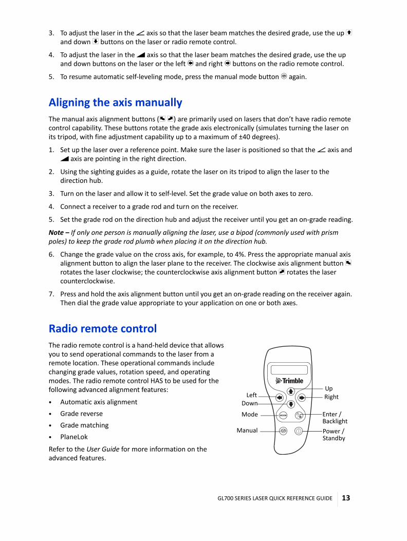
Radio remote control The radio remote control is a hand-held device that allows you to send operational commands to the laser from a remote location. These operational commands include changing grade values, rotation speed, and operating modes. The radio remote control HAS to be used for the following advanced alignment features:
• Automatic axis alignment• Grade reverse• Grade matching• PlaneLok
Refer to the User Guide for more information on the advanced features.
MODE
Power /
Mode Enter /
Up
Down
ManualStandby
Backlight
RightLeft
GL700 SERIES LASER QUICK REFERENCE GUIDE 13

A solid “T” symbol appears in the right corner of the LCD to indicate that the link between the radio remote control and laser is complete. A flashing bar above the “T” indicates that communication with the laser is established. When the radio remote control is connected to a receiver, an “R” appears in the right corner of the radio remote control’s first display line indicating that a connection has been made and the power is on.
When using the radio remote control, make sure its antenna is pointing skyward. For example, if you’re using the radio remote control in the horizontal position, such as you would when holding the radio remote control in your hand, the antenna should be at a 90° angle to the radio remote control. If you are using the radio remote control in the vertical position, such as you would when connecting it to a grade rod, the antenna should be sticking up from the top of the radio remote control.
Turning on/off the radio remote control1. Press the power button to turn on the radio remote control.
When the radio remote control is initially turned on, the axes symbols and last-entered grade for each axis appear in the LCD.
2. To turn off the radio remote control, press and hold the power button for 3 seconds.
Selecting the operational modeThe mode button allows you to choose the laser’s operational mode, which includes changing grade, automatic axis alignment, grade matching, PlaneLok, grade reverse, and beam rotation speed.
1. Repeatedly press and release the mode button to cycle through the operational mode menu. The menu selections appear on the radio remote control’s LCD.
2. Press the enter button to confirm your selection.
GL700 SERIES LASER QUICK REFERENCE GUIDE 14

Legal NoticesCorporate OfficeTrimble Construction Division 5475 Kellenburger Road Dayton, Ohio 45424-1099 U.S.A.
Copyright and Trademarks© 2002–2014, Trimble Navigation Limited. All rights reserved. Trimble, the Globe & Triangle logo, and Spectra Precision are trademarks of Trimble Navigation Limited, registered in the United States and in other countries. All other trademarks are the property of their respective owners.
Release NoticeThis is the December 2014 release (Revision C) of the GL700 Series Laser Quick Reference Guide, part number 1445-0730. It applies to version 3.75 of the GL700 Series lasers.
Product warranty informationFor applicable product warranty information, please refer to the information in the Spectra Precision GL700 Series Laser Transmitter User Guide, or consult your Trimble reseller.
EMC Declaration of ConformityThis laser has been tested and found to comply with the limits for a Class B digital device for radio noise for digital apparatus set out in the Radio Interference Regulations of the Canadian Department of Communication, and is pursuant to part 15 of the Federal Communication Commission (FCC) rules. These limits are designed to provide reasonable protection against harmful interference in a residential installation. This laser generates radio frequency. If it is not used in accordance with the instructions, it may cause harmful interference to radio or television reception. Such interference can be determined by turning the laser off and on. You are encouraged to try eliminating the interference by one or more of the following measures:
– Reorient or relocate the receiving antenna.– Increase the separation between the laser and the receiver.
For more information, consult your dealer or an experienced radio/television technician.
C CAUTION – Changes or modifications to the laser that are not expressly approved by Trimble could void authority to use the equipment.
Application of Council Directive(s) 2004/108/EC and 2006/95/EC
Manufacturer's Name Trimble Navigation Limited
Manufacturer's Address 5475 Kellenburger RoadDayton, Ohio 45424-1099U.S.A.
European Representative Address Trimble GmbH AM Prime Parc 11 D-65479 Raunheim, Germany
Model Number(s) GL710, 720, 722, 750, 760, and 762
Conformance to Directive(s) 2004/108/EC (EMC Directive) using EN 61000-4-2:2001, EN61000-4-3:2006, EN61000-3-2:2005 with A1:2006, EN61000-3-3:1995, EN 55022:2006, ISO 14982:2009 "including Clause 7", and EN13309:20102006/93/EC (Low Voltage Directive) using EN 60825-1:20071999/5/EC (RTTE Directive) using ETSI EN301489-17 V2.2.1 and ETSI EN301489-1 V1.8.1
Equipment Type/Environment Agriculture, Forestry, and Construction
Product Standards ETSI EN 301489-17 V2.2.1ETSI EN 301489-1 V1.8.1EN 55022:2006EN61000-4-2:2001EN61000-4-3:2006EN61000-3-2:2005 with A1:2006EN61000-3-3:1995ISO 14982:2009" including Clause 7"EN 13309:2010EN 60825-1:2007
GL700 SERIES LASER QUICK REFERENCE GUIDE 15

IFETEL NOM 121 GL722: RCPTRGL14-1639GL722s: RCPTRGL14-1639-A1RC703: RCPTRRC14-1640RC703s: RCPTRRC14-1640-A1
NYCE NOM-001-SCFI-1993 ADAPTADOR DE ca/cc Modelo(s): AN5808 Certificado no. 1402CE11706
GL700 SERIES LASER QUICK REFERENCE GUIDE 16