quick reference guide - gps farming · do read the manual in its entirety before using viper. 4....
TRANSCRIPT
VIPER
Qu
ick Reference G
uid
eV
ersion
2.0
7
1
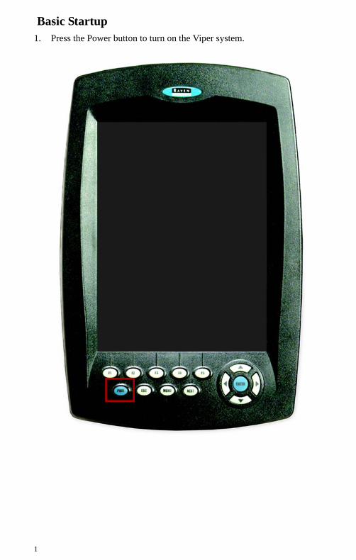
Basic Startup1. Press the Power button to turn on the Viper system.
2
Viper Do’s and Don’ts1. Do have a flashdisk in the Viper at all times, including for Power-on.
2. Do have the Viper serial number and firmware revision available when calling for technical assistance. It is best if the user is in the machine and in front of the Viper when calling for tech support.
3. Do read the manual in its entirety before using Viper.
4. Do power the DGPS receiver and the Raven console or CANBus system before powering Viper.
5. Don’t turn Viper off when in a job, without properly closing the job first. If Viper loses power when in a job, job files will not be saved and the associated files will be corrupt.
6. Don’t connect Viper to a switched source. Always connect to a battery or other unswitched source.
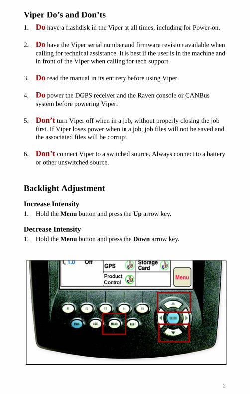
Backlight Adjustment
Increase Intensity1. Hold the Menu button and press the Up arrow key.
Decrease Intensity1. Hold the Menu button and press the Down arrow key.
3
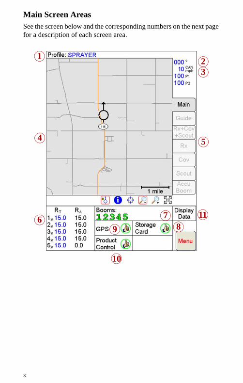
Main Screen AreasSee the screen below and the corresponding numbers on the next page for a description of each screen area.
6
1
4
32
5
79 8
10
11
4
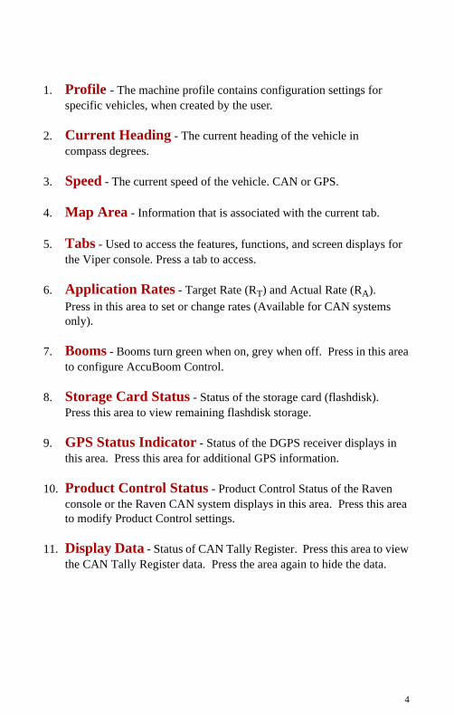
1. Profile - The machine profile contains configuration settings for specific vehicles, when created by the user.
2. Current Heading - The current heading of the vehicle in compass degrees.
3. Speed - The current speed of the vehicle. CAN or GPS.
4. Map Area - Information that is associated with the current tab.
5. Tabs - Used to access the features, functions, and screen displays for the Viper console. Press a tab to access.
6. Application Rates - Target Rate (RT) and Actual Rate (RA). Press in this area to set or change rates (Available for CAN systems only).
7. Booms - Booms turn green when on, grey when off. Press in this area to configure AccuBoom Control.
8. Storage Card Status - Status of the storage card (flashdisk). Press this area to view remaining flashdisk storage.
9. GPS Status Indicator - Status of the DGPS receiver displays in this area. Press this area for additional GPS information.
10. Product Control Status - Product Control Status of the Raven console or the Raven CAN system displays in this area. Press this area to modify Product Control settings.
11. Display Data - Status of CAN Tally Register. Press this area to view the CAN Tally Register data. Press the area again to hide the data.
5
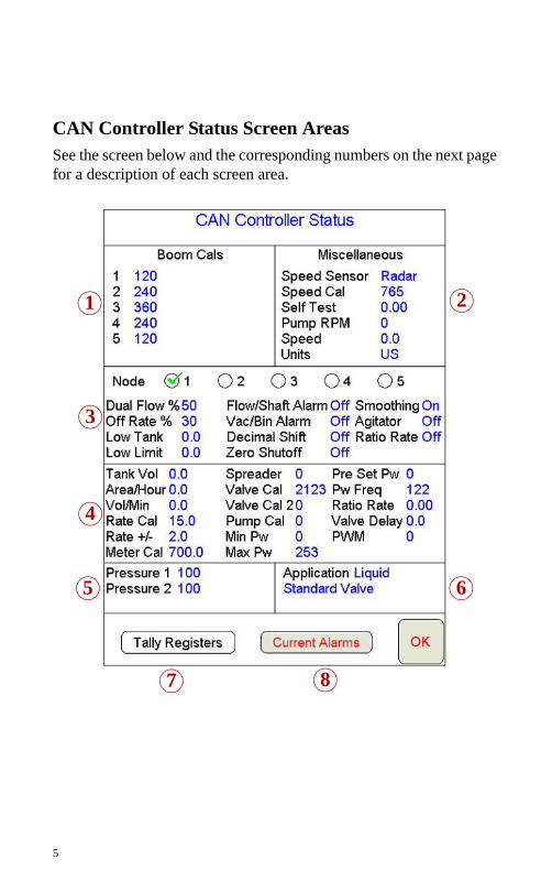
CAN Controller Status Screen AreasSee the screen below and the corresponding numbers on the next page for a description of each screen area.
6
1
4
3
2
5
7 8
6
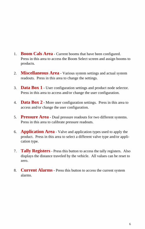
1. Boom Cals Area - Current booms that have been configured. Press in this area to access the Boom Select screen and assign booms to products.
2. Miscellaneous Area - Various system settings and actual system readouts. Press in this area to change the settings.
3. Data Box 1 - User configuration settings and product node selector. Press in this area to access and/or change the user configuration.
4. Data Box 2 - More user configuration settings. Press in this area to access and/or change the user configuration.
5. Pressure Area - Dual pressure readouts for two different systems. Press in this area to calibrate pressure readouts.
6. Application Area - Valve and application types used to apply the product. Press in this area to select a different valve type and/or appli-cation type.
7. Tally Registers - Press this button to access the tally registers. Also displays the distance traveled by the vehicle. All values can be reset to zero.
8. Current Alarms - Press this button to access the current system alarms.
MSy
StSy
7
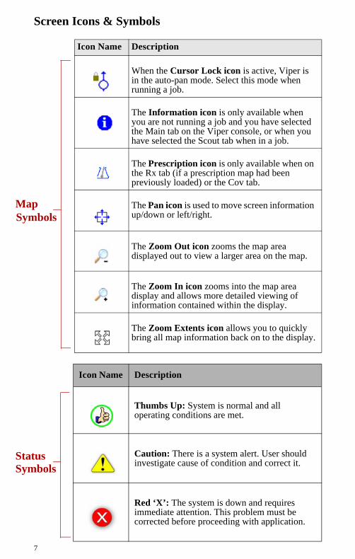
Screen Icons & Symbols
Icon Name Description
When the Cursor Lock icon is active, Viper is in the auto-pan mode. Select this mode when running a job.
The Information icon is only available when you are not running a job and you have selected the Main tab on the Viper console, or when you have selected the Scout tab when in a job.
The Prescription icon is only available when on the Rx tab (if a prescription map had been previously loaded) or the Cov tab.
The Pan icon is used to move screen information up/down or left/right.
The Zoom Out icon zooms the map area displayed out to view a larger area on the map.
The Zoom In icon zooms into the map area display and allows more detailed viewing of information contained within the display.
The Zoom Extents icon allows you to quickly bring all map information back on to the display.
Icon Name Description
Thumbs Up: System is normal and all operating conditions are met.
Caution: There is a system alert. User should investigate cause of condition and correct it.
Red ‘X’: The system is down and requires immediate attention. This problem must be corrected before proceeding with application.
ap mbols
atusmbols
8
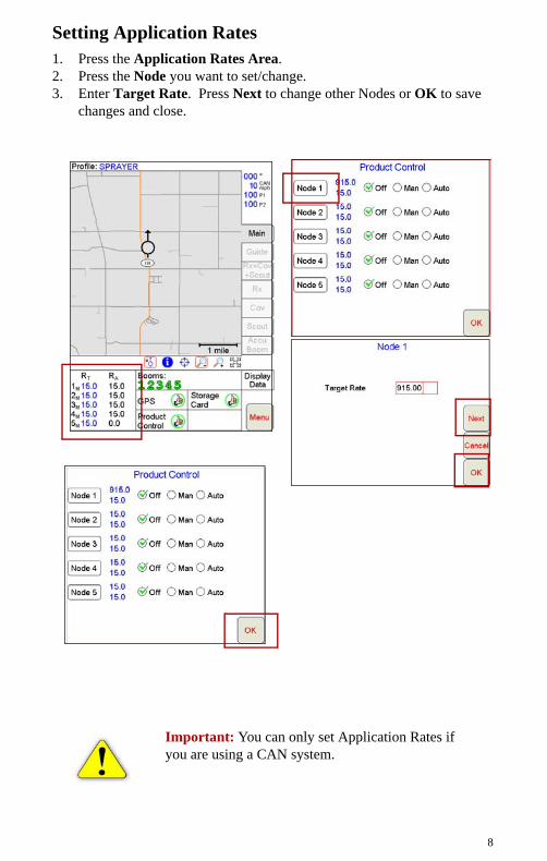
Setting Application Rates1. Press the Application Rates Area. 2. Press the Node you want to set/change. 3. Enter Target Rate. Press Next to change other Nodes or OK to save
changes and close.
Important: You can only set Application Rates if you are using a CAN system.
9
Profiles
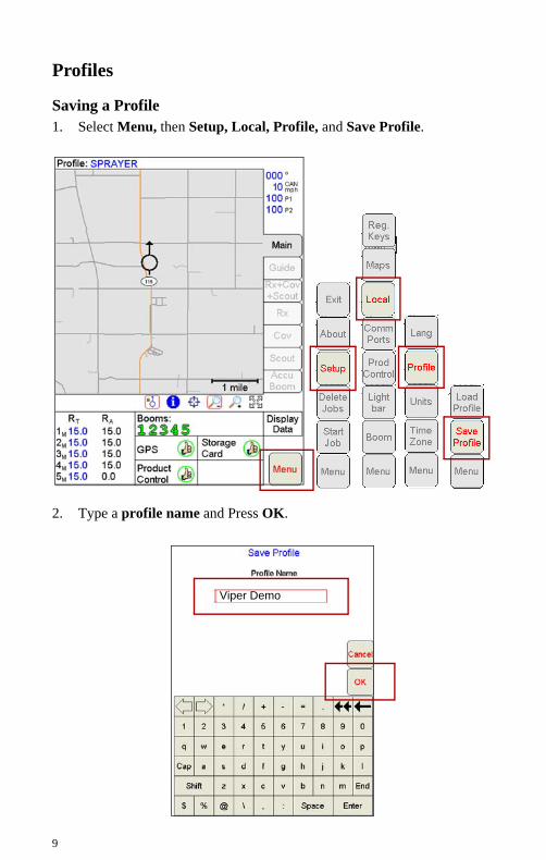
Saving a Profile1. Select Menu, then Setup, Local, Profile, and Save Profile.
2. Type a profile name and Press OK.
Viper Demo
1 0
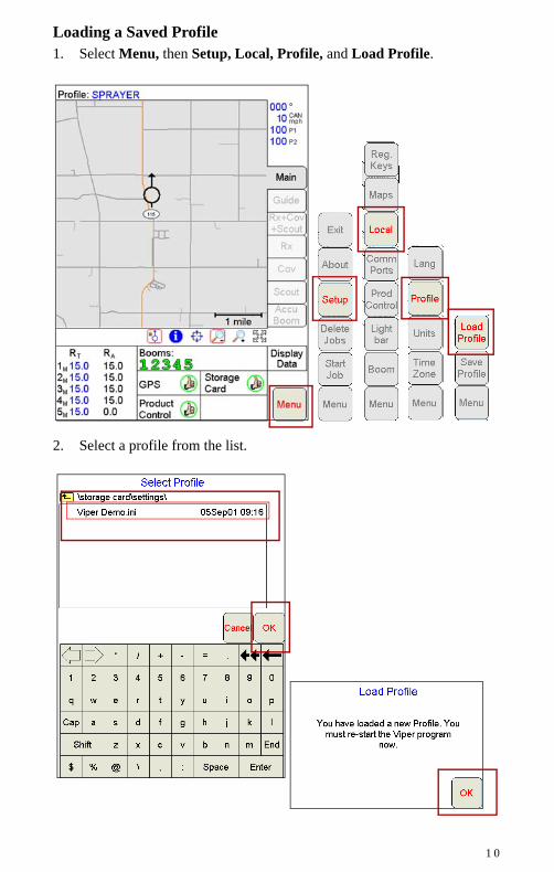
Loading a Saved Profile1. Select Menu, then Setup, Local, Profile, and Load Profile.
2. Select a profile from the list.
1 1
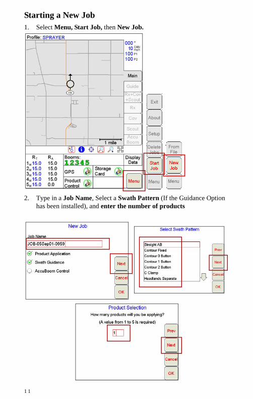
Starting a New Job1. Select Menu, Start Job, then New Job.
2. Type in a Job Name, Select a Swath Pattern (If the Guidance Option has been installed), and enter the number of products
1 2
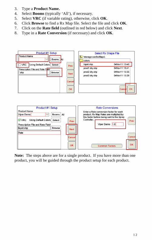
3. Type a Product Name. 4. Select Booms (typically ‘All’), if necessary.5. Select VRC (if variable rating), otherwise, click OK.6. Click Browse to find a Rx Map file. Select the file and click OK.7. Click on the Rate field (outlined in red below) and click Next.8. Type in a Rate Conversion (if necessary) and click OK.
Note: The steps above are for a single product. If you have more than one product, you will be guided through the product setup for each product.
1 3
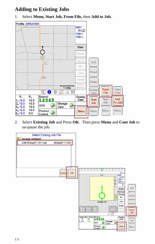
Adding to Existing Jobs1. Select Menu, Start Job, From File, then Add to Job.
2. Select Existing Job and Press OK. Then press Menu and Cont Job to un-pause the job.
1 4
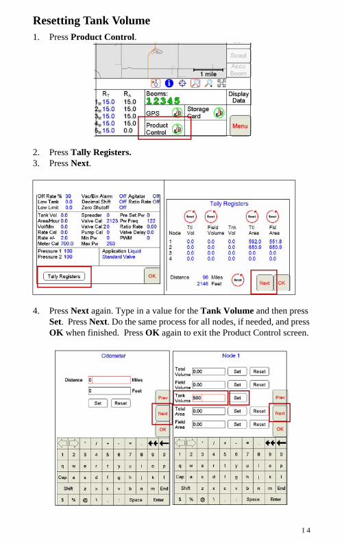
Resetting Tank Volume1. Press Product Control.
2. Press Tally Registers.3. Press Next.
4. Press Next again. Type in a value for the Tank Volume and then press Set. Press Next. Do the same process for all nodes, if needed, and press OK when finished. Press OK again to exit the Product Control screen.
1 5
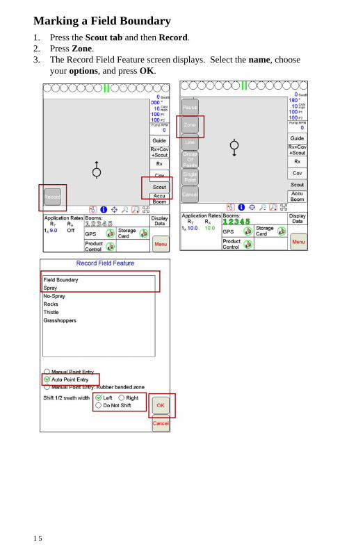
Marking a Field Boundary1. Press the Scout tab and then Record.2. Press Zone. 3. The Record Field Feature screen displays. Select the name, choose
your options, and press OK.
1 6
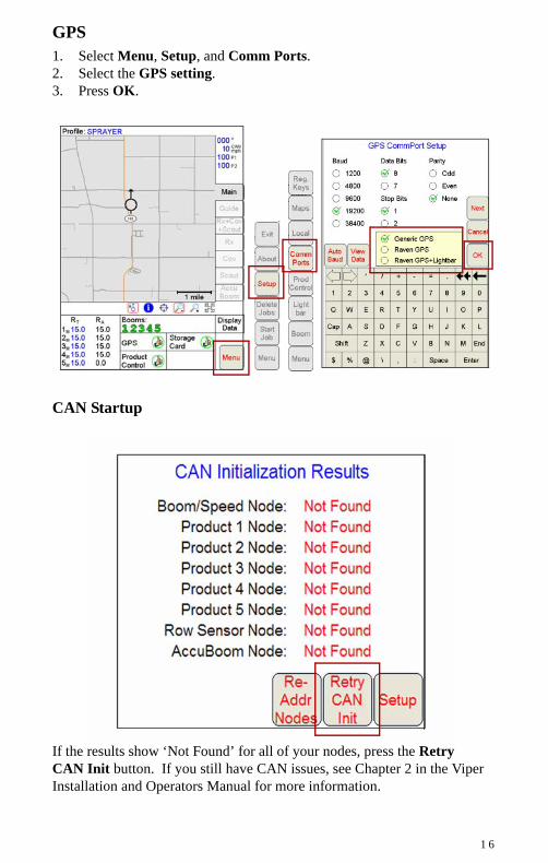
GPS1. Select Menu, Setup, and Comm Ports. 2. Select the GPS setting.3. Press OK.
CAN Startup
If the results show ‘Not Found’ for all of your nodes, press the Retry CAN Init button. If you still have CAN issues, see Chapter 2 in the Viper Installation and Operators Manual for more information.

1 7
AccuBoom Setup1. Press the Booms Area. 2. Enter Look-Ahead values and press Next. 3. Select the booms to control and press OK.
1 8
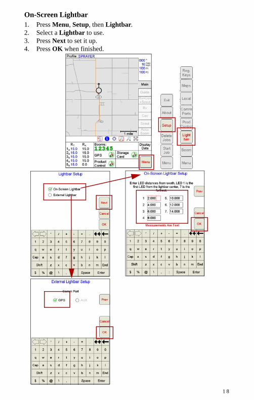
On-Screen Lightbar1. Press Menu, Setup, then Lightbar. 2. Select a Lightbar to use. 3. Press Next to set it up. 4. Press OK when finished.
1 9
Troubleshooting
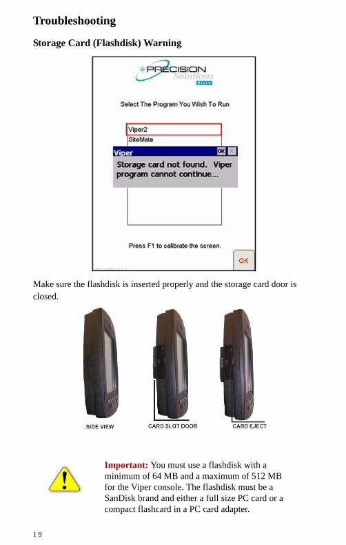
Storage Card (Flashdisk) Warning
Make sure the flashdisk is inserted properly and the storage card door is closed.
Important: You must use a flashdisk with a minimum of 64 MB and a maximum of 512 MB for the Viper console. The flashdisk must be a SanDisk brand and either a full size PC card or a compact flashcard in a PC card adapter.
2 0
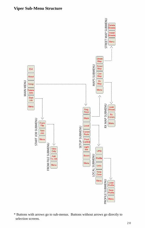
Viper Sub-Menu Structure
* Buttons with arrows go to sub-menus. Buttons without arrows go directly to selection screens.
M
AIN
MEN
U
SETU
P SU
BM
ENU
ST
ART
JO
B S
UB
MEN
U
M
APS
SU
BM
ENU
STRE
ET M
AP
SUB
MEN
U
RX M
AP
SUB
MEN
U
LO
CA
L SU
BM
ENU
PRO
FILE
SU
BM
ENU
FRO
M F
ILE
SUB
MEN
U

V
Raven Industries Toll Free 800-243-5435Flow Controls Division Fax 605-331-0426P.O. Box 5107 www.ravenprecision.comSioux Falls, SD 57117-5107 [email protected]
Vip
er Qu
ick Reference G
uid
e - Version
2.07 (P/N 016-0171-026 Rev C
06/06)
Notice: This document and the information provided are the property of Raven Industries, Inc. and may only be used as authorized by Raven Industries, Inc. All rights reserved under the copyright laws.