quick install manual - · pdf filequick install manual ... most important safety requirements...
TRANSCRIPT

EM-BNET-Controller www.daikinac.com 6/16
Quick Install Manual750-831 BACnet®/IP Controller

2 www.daikinac.com EM-BNET-Controller EM-BNET-Controller www.daikinac.com 3
Table of Contents
1. Controller Overview ..................................................................................................4
1.1 General Information ................................................................................4
1.2 Device Data ...............................................................................................5
1.3 System Data .............................................................................................5
1.4 Power Supply Technical Data ..................................................................6
1.5 Field Wiring Connection Data .................................................................6
1.6 Environmental Conditions Data .............................................................6
1.7 Mechanical Strength Data .......................................................................72. Storage, Assembly and Transport ...........................................................................7
3. Device power .............................................................................................................7
3.1 Power Supply - Isolation .........................................................................8
3.2 Power Supply - Connection ....................................................................84. Power Supply Unit ....................................................................................................9
5. Fieldbus Connection ...............................................................................................10
6. Special Use Conditions for ETHERNET Devices ..................................................10
7. Controller Display Elements ...................................................................................11
8. Mounting onto Carrier Rail .....................................................................................12
8.1 Carrier Rail Properties ...........................................................................12
8.2 Spacing ...................................................................................................12
8.3 Mounting Sequence ..............................................................................12
8.4 Inserting and Removing Devices .........................................................13
8.5 Inserting the Fieldbus Coupler/Controller ...........................................13
8.6 Removing the Fieldbus Coupler/Controller ........................................13
8.7 Inserting the I/O Module .......................................................................14
8.8 Removing the I/O Module .....................................................................14
8.9 Installation Position ...............................................................................149. Data Contacts/Internal Bus .....................................................................................15
10. Power Contacts/Field Supply .................................................................................15
11. Connecting a Conductor to the CAGE CLAMP® ...................................................15

2 www.daikinac.com EM-BNET-Controller EM-BNET-Controller www.daikinac.com 3
Notes About this ManualAll sequences implemented on WAGO-I/O-SYSTEM 750 devices may only be carried out by electrical specialists with sufficient knowledge in automation. The specialists must be familiar with the current norms and guidelines for the devices and automated environments. All changes to the coupler or controller should always be carried out by qualified personnel with sufficient skills in controller programming
Legal BasisThis purpose of this document is to serve a quick installation guide for 750-831 BACnet®/IP controller. This document does not replace, undermine, diminish or in any way reduce the usefulness of WAGO Kontakttechnik GmbH & Co. KG’s technical manual concerning the 750-831 BACnet/IP controller, which can be downloaded from www.daikinac.com or www.wago.com. This document is based on WAGO Kontakttechnik GmbH & Co. KG’s technical manual version 1.20.
Safety GuidelinesThis section includes an overall summary of the most important safety requirements and notes that are mentioned in each individual section. To protect your health and prevent damage to devices as well, it is imperative to read and carefully follow the safety guidelines
1. All power sources to the device shall be switched off prior to performing any installation, repair or maintenance work.
2. Install the device only in appropriate housings, cabinets or in electrical operation rooms. The WAGO-I/O-SYSTEM 750 and its components are an open system. As such, install the system and its components exclusively in appropriate housings, cabinets or in electrical operation rooms. Allow access to such equipment and fixtures to authorized, qualified staff only by means of specific keys or tools.
3. Only use devices equipped with ETHERNET or RJ-45 connectors used for LANs. Never connect these devices with telecommunication networks.
4. Replace defective or damaged devices: Replace defective or damaged device/module (e.g., in the event of deformed contacts), since the long-term functionality of device/module involved can no longer be ensured
5. Protect the components against materials having seeping and insulating properties. The components are not resistant to materials having seeping and insulating properties such as: aerosols, silicones and triglycerides (found in some hand creams). If you cannot exclude that such materials will appear in the component environment, then install the components in an enclosure being resistant to the above-mentioned materials. Clean tools and materials are imperative for handling devices/modules.
6. Clean soiled contacts using oil-free compressed air or with ethyl alcohol and leather cloths.
7. Do not use any contact spray. The spray may impair contact area functionality in connection with contamination.
8. Avoid electrostatic discharge. The devices are equipped with electronic components that may be destroyed by electrostatic discharge when touched. Please observe the safety precautions against electrostatic discharge per DIN EN 61340-5-1/-3. When handling the devices, please ensure that environmental factors (personnel, work space and packaging) are properly grounded
9. When using carrier rail grounding be sure to check technical manual for 750-831.
About this Manual

4 www.daikinac.com EM-BNET-Controller EM-BNET-Controller www.daikinac.com 5
Controller Overview
1. Controller Overview
1.1 General InformationThe view below shows the three parts of the device:
• The fieldbus connection is on the left side.• LEDs for operation status, bus communica-
tion, error messages and diagnostics, as well as the service interface are in the middle area.
• The right side shows the power supply unit for the system supply and for the field supply of the attached I/O modules via power jumper contacts. LEDs show the status of the operating voltage for the system and field power (jumper contacts).
View BACnet®/IP Controller

4 www.daikinac.com EM-BNET-Controller EM-BNET-Controller www.daikinac.com 5
Controller Overview
1.2 Device Data
1.3 System Data
(*) SD Card is field supplied. (**) Using the Ethernet.lib, when the SysLibSocket.lib is used, there are 143. (***) This value is valid for brand-new devices with an ambient temperature of 25 °C, 77 °F. The guaranteed buffer time for the real
time clock is reduced with rising temperature and operating time.

6 www.daikinac.com EM-BNET-Controller EM-BNET-Controller www.daikinac.com 7
1.4 Power Supply Technical Data
1.5 Field Wiring Connection Data
1.6 Environmental Conditions Data
Note: high temperatures lead to a reduced buffer time for the real time clock
Controller Overview
6 www.daikinac.com EM-BNET-Controller EM-BNET-Controller www.daikinac.com 7
Controller Overview / Storage, Assembly and Transport
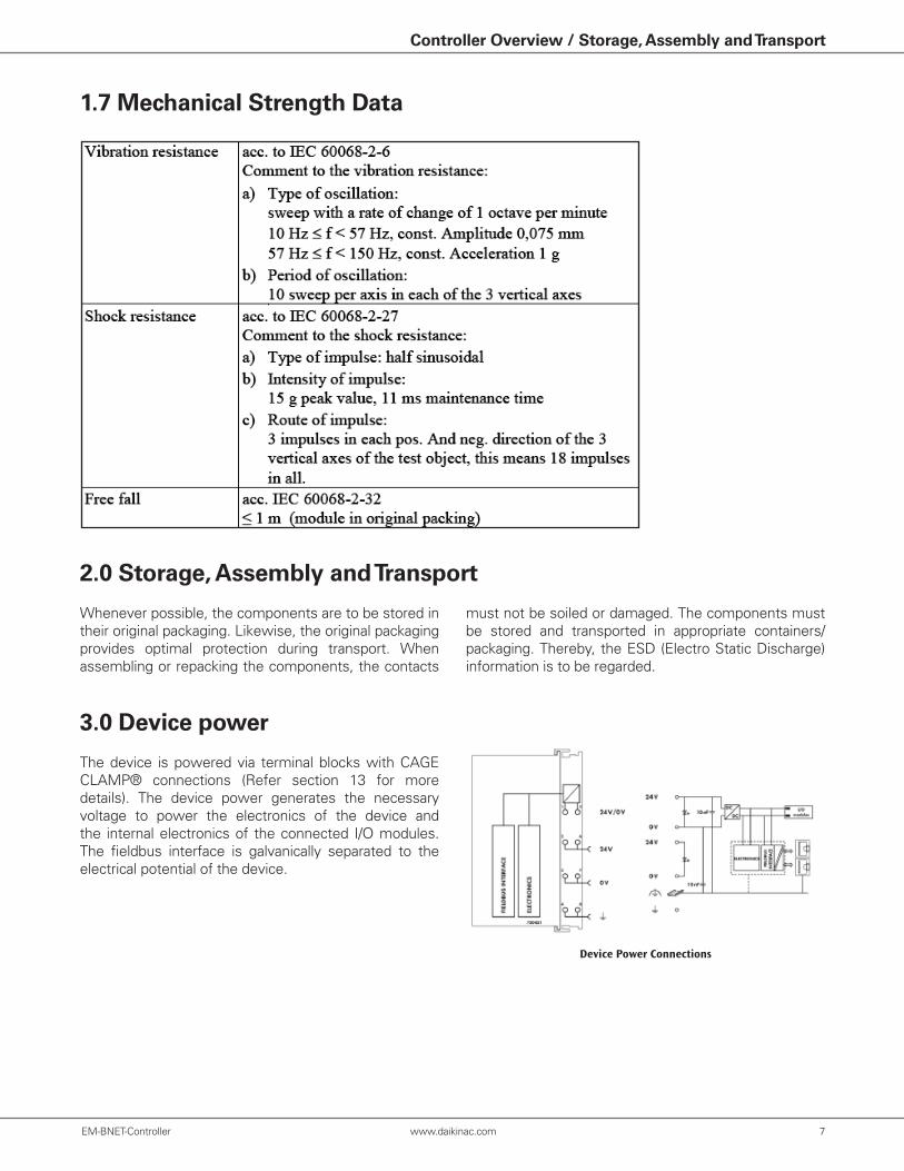
1.7 Mechanical Strength Data
2.0 Storage, Assembly and Transport
3.0 Device power
Whenever possible, the components are to be stored in their original packaging. Likewise, the original packaging provides optimal protection during transport. When assembling or repacking the components, the contacts
The device is powered via terminal blocks with CAGE CLAMP® connections (Refer section 13 for more details). The device power generates the necessary voltage to power the electronics of the device and the internal electronics of the connected I/O modules. The fieldbus interface is galvanically separated to the electrical potential of the device.
must not be soiled or damaged. The components must be stored and transported in appropriate containers/packaging. Thereby, the ESD (Electro Static Discharge) information is to be regarded.
Device Power Connections

8 www.daikinac.com EM-BNET-Controller EM-BNET-Controller www.daikinac.com 9
Storage, Assembly and Transport
3.1 Power Supply - Isolation
3.2 Power Supply - Connection
Within the fieldbus node, there are three electrically isolated potentials:
• Electrically isolated fieldbus interface via transformer
• Electronics of the fieldbus couplers/controllers and the I/O modules (internal bus)
• All I/O modules have an electrical isolation between the electronics (internal bus, logic) and the field electronics. Some digital and analog input modules have each channel electrically isolated, please see catalog.
Isolation for Fieldbus Couplers/Controllers (Example)
System Power via Fieldbus Coupler/Controller (left) and via Internal System Supply Module (right)
The WAGO-I/O-SYSTEM 750 requires a 24V direct current system supply. The power supply is provided via the fieldbus coupler/controller and, if necessary, in addition via internal system supply modules 750-613. The power supply is protected is against reverse voltage.
Position Description
1 System supply DC 24 V (-25%. . . +30%)
2 System supply O V
Do not use an incorrect voltage/frequency. The use of an incorrect supply voltage or frequency can cause severe
damage to the components.

8 www.daikinac.com EM-BNET-Controller EM-BNET-Controller www.daikinac.com 9
Storage, Assembly and Transport / Power Supply Unit
4. Power Supply Unit
System Voltage for Standard Couplers/Controllers and Extended ECO Couplers
Only reset the system simultaneously for all power modules. Reset the system by simultaneously switching the system power at all power modules
(fieldbus coupler/controller and potential power module with bus power supply) off and on again.
The WAGO-I/O-SYSTEM 750 requires a 24 VDC voltage (system supply). Recommended part number is 787-712NOTE: Regulated power supplies should always be used to ensure the quality of the supply voltage.
For brief voltage dips, a buffer (200μF per 1A load current) must be provided.NOTE: The power failure time of 10 ms according to IEC 61131-2 is not maintained in a maximum configuration.
The power demand must be determined individually depending on the entry point of the field power. All loads through field devices and I/O modules must be taken into account. The field power also impacts the I/O modules because the input and output drivers of some I/O modules require the voltage of the field supply.NOTE: The system power and field power must be isolated to ensure bus operation in the event of short circuits on the actuator side.

10 www.daikinac.com EM-BNET-Controller EM-BNET-Controller www.daikinac.com 11
Fieldbus Connection / Special Use Conditions for ETHERNET Devices
The connection to the ETHERNET based fieldbuses is made via two RJ-45 plugs which are connected to the fieldbus controller via an integrated switch. The integrated switch works in store-and-forward operation and for each port, supports the transmission speeds 10/100 Mbit as well as the transmission modes full and half-duplex. The wiring of these plugs corresponds to the specifications for 100BaseTX, which prescribes a category 5 twisted pair cable as the connecting cable. Cable types S-UTP (Screened Unshielded Twisted Pair) and STP (Shielded Twisted Pair) with a maximum segment length of 100m (approximately 328.08 feet) can be used. The RJ-45 socket is arranged physically lower, allowing the coupler to fit in a 3.15 in (80 mm) high enclosure once connected.
RJ-45 Connector
5. Fieldbus Connection
Contact Signal
1 TD + Transmit +2 TD - Transmit -3 RD + Receive +4 free5 free6 RD - Receive -7 free8 free
Only use devices equipped with ETHERNET or RJ-45 connectors used for LANs. Never connect these devices with telecommunication networks.
6. Special Use Conditions for ETHERNET Devices• If not otherwise specified, ETHERNET devices are
intended for use on local networks. Please note the following when using ETHERNET devices in your system:
– Do not connect control components and control networks to an open network such as the Internet or an office network. WAGO recom-mends putting control components and control networks behind a firewall.
– Limit physical and electronic access to all automation components to authorized personnel only.
– Change the default passwords before first use, This will reduce the risk of unauthorized access to your system.
– Regularly change the passwords used, This will reduce the risk of unauthorized access to your system.
– If remote access to control components and control networks is required, use a Virtual Private Network (VPN).
– Regularly perform threat analyses. You can check whether the measures taken meet your security requirements.
– Use “defense-in-depth” mechanisms in your system’s security configuration to restrict the access to and control of individual products and networks.

10 www.daikinac.com EM-BNET-Controller EM-BNET-Controller www.daikinac.com 11
The operating condition of the fieldbus controller or the node is displayed with the help of illuminated indicators in the form of light-emitting diodes (LEDs). The LED information is routed to the top of the case by light fibres. In some cases, these are multi-colored (red, green or red/green (=orange)).
For the diagnostics of the different domains fieldbus, node and supply voltage, the LEDs can be divided into three groups:
1. Fieldbus status LED
Control Display Element
7. Controller Display Elements
Display Elements
LED Color MeaningLNK ACT 1 green Indicates a connection to the physical network at port 1
LNK ACT 2 green Indicates a connection to the physical network at port 2
MS/BT
green/ green/blinking/ red/ red blinking
Indicates the node or BACnet® status
NS red/green Indicates the network status
LED Color Meaning
I/Ored/green/orange Indicates the operation of the node and signals via a blink code faults encountered.
USRred/green/orange
Indicates information to the Internal bus faults, controlled from the user program according to the visualization programming.
LED Color Meaning
A green Indicates the status of the operating voltage – system
B green Indicates the status of the operating voltage – power jumper contacts
2. Node status LED
3. Supply voltage LED

12 www.daikinac.com EM-BNET-Controller EM-BNET-Controller www.daikinac.com 13
Mounting onto Carrier Rail
All system components can be snapped directly onto a carrier rail in accordance with the European standard EN 50022 (DIN 35).Carrier rails have different mechanical and electrical properties. For the optimal system setup on a carrier rail, certain guidelines must be observed:
The spacing between adjacent components, cable conduits, and casing and frame sides must be maintained for the complete fieldbus node.The spacing creates room for heat transfer, installation or wiring. The spacing to cable conduits also prevents conducted electromagnetic interferences from influencing the operation.
Fieldbus couplers/controllers and I/O modules of the WAGO-I/O-SYSTEM 750/753 are snapped directly on a carrier rail in accordance with the European standard EN 50022 (DIN 35). The reliable positioning and connection is made using a tongue and groove system. Due to the automatic locking, the individual devices are securely seated on the rail after installation.Starting with the fieldbus coupler/controller, the I/O modules are mounted adjacent to each other according to the project design. Errors in the design of the node in terms of the potential groups (connection via the power contacts) are recognized, as the I/O modules with power contacts (blade contacts) cannot be linked to I/O modules with fewer power contacts.
8. Mounting onto Carrier Rail
8.2 Spacing
8.3 Mounting Sequence
• The material must be non-corrosive.• Most components have a contact to the carrier rail
to ground electromagnetic disturbances. In order to avoid corrosion, this tin-plated carrier rail contact must not form a galvanic cell with the material of the carrier rail which generates a differential voltage above 0.5 V (saline solution of 0.3 % at 68°F [20°C]).
• The carrier rail must optimally support the EMC measures integrated into the system and the shielding of the I/O module connections.
• A sufficiently stable carrier rail should be selected and, if necessary, several mounting points (every 7.87 in or 20 cm) should be used in order to prevent bending and twisting (torsion).
• The geometry of the carrier rail must not be altered in order to secure the safe hold of the components. In particular, when shortening or mounting the carrier rail, it must not be crushed or bent.
• The base of the I/O components extends into the profile of the carrier rail. For carrier rails with a height of 7.5 mm or 0.3 inches, mounting points are to be riveted under the node in the carrier rail (slotted head captive screws or blind rivets).
• The metal springs on the bottom of the housing must have low-impedance contact with the DIN rail (wide contact surface is possible).
Risk of injury due to sharp-edged blade contacts, The blade contacts are sharp-edged. Handle the I/O module carefully to prevent injury.
Insert I/O modules only from the proper direction, All I/O modules feature grooves for power jumper contacts on the right side. For some I/O modules, the grooves are closed on the top. Therefore, I/O modules featuring a power jumper contact on the left side cannot be snapped from the top. This mechanical coding helps to avoid configuration errors, which may destroy the I/O modules. Therefore, insert I/O modules only from the right and from the top
Don’t forget the bus end module, Always plug a bus end module 750-600 onto the end of the fieldbus node, You must always use a bus end module at all fieldbus nodes with WAGO-I/O SYSTEM 750 fieldbus couplers/controllers to guarantee proper data transfer. The controller needs at least one IO module to function.
12 www.daikinac.com EM-BNET-Controller EM-BNET-Controller www.daikinac.com 13
Perform work on devices only if they are de-energized, Working on energized devices can damage them. Therefore, turn off the power supply before working on the devices.
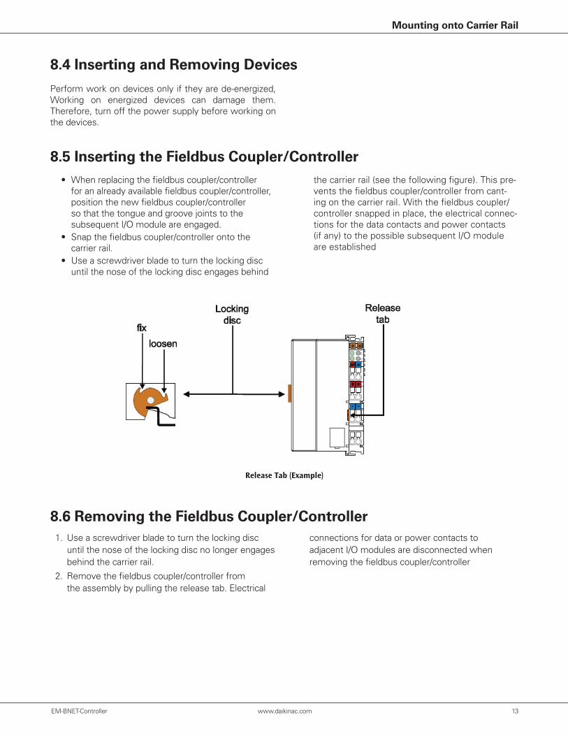
• When replacing the fieldbus coupler/controller for an already available fieldbus coupler/controller, position the new fieldbus coupler/controller so that the tongue and groove joints to the subsequent I/O module are engaged.
• Snap the fieldbus coupler/controller onto the carrier rail.
• Use a screwdriver blade to turn the locking disc until the nose of the locking disc engages behind
8.4 Inserting and Removing Devices
8.5 Inserting the Fieldbus Coupler/Controller
8.6 Removing the Fieldbus Coupler/Controller
Mounting onto Carrier Rail
the carrier rail (see the following figure). This pre-vents the fieldbus coupler/controller from cant-ing on the carrier rail. With the fieldbus coupler/controller snapped in place, the electrical connec-tions for the data contacts and power contacts (if any) to the possible subsequent I/O module are established
Release Tab (Example)
1. Use a screwdriver blade to turn the locking disc until the nose of the locking disc no longer engages behind the carrier rail.
2. Remove the fieldbus coupler/controller from the assembly by pulling the release tab. Electrical
connections for data or power contacts to adjacent I/O modules are disconnected when removing the fieldbus coupler/controller
14 www.daikinac.com EM-BNET-Controller EM-BNET-Controller www.daikinac.com 15
Mounting onto Carrier Rail
8.7 Inserting the I/O Module
8.8 Removing the I/O Module
8.9 Installation Position
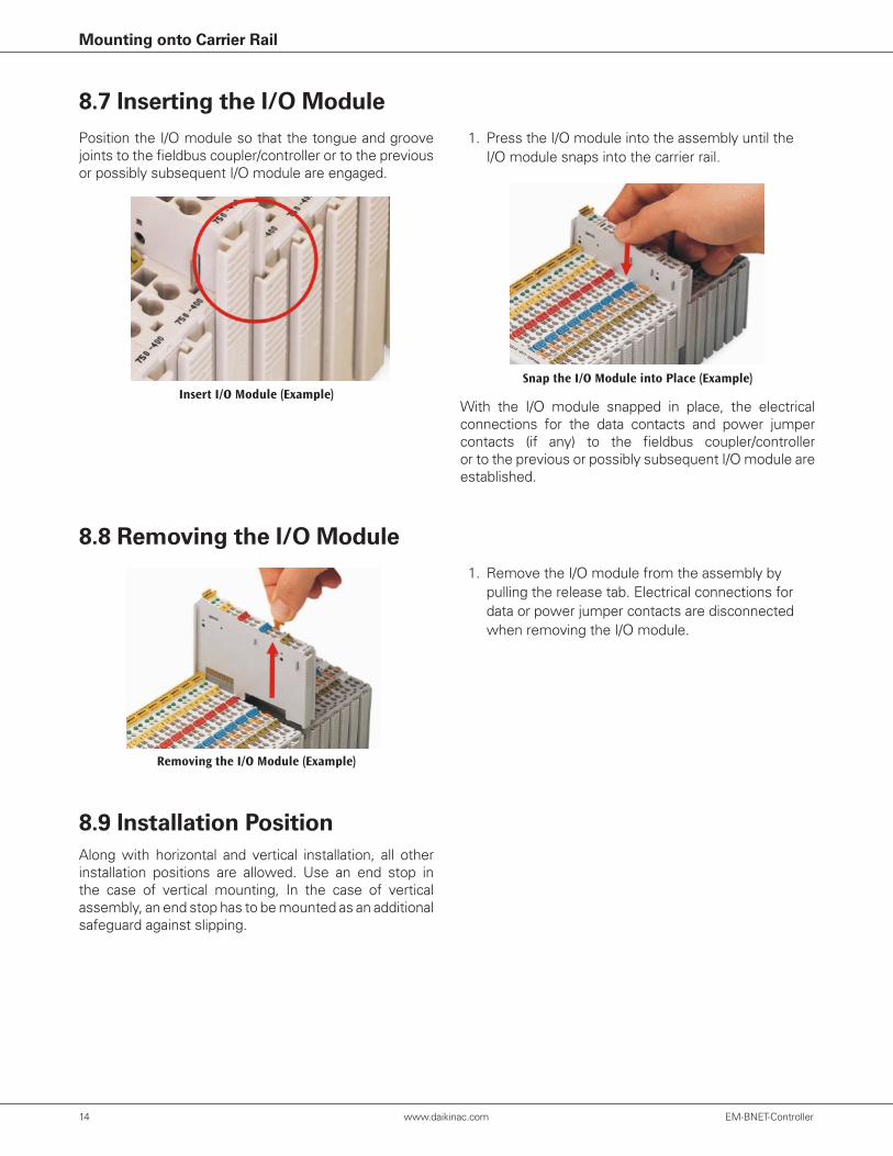
Position the I/O module so that the tongue and groove joints to the fieldbus coupler/controller or to the previous or possibly subsequent I/O module are engaged.
Along with horizontal and vertical installation, all other installation positions are allowed. Use an end stop in the case of vertical mounting, In the case of vertical assembly, an end stop has to be mounted as an additional safeguard against slipping.
With the I/O module snapped in place, the electrical connections for the data contacts and power jumper contacts (if any) to the fieldbus coupler/controller or to the previous or possibly subsequent I/O module are established.
Insert I/O Module (Example)Snap the I/O Module into Place (Example)
Removing the I/O Module (Example)
1. Press the I/O module into the assembly until the I/O module snaps into the carrier rail.
1. Remove the I/O module from the assembly by pulling the release tab. Electrical connections for data or power jumper contacts are disconnected when removing the I/O module.
14 www.daikinac.com EM-BNET-Controller EM-BNET-Controller www.daikinac.com 15
Data Contacts/Internal Bus / Power Contacts/Field Supply / Connecting a Conductor
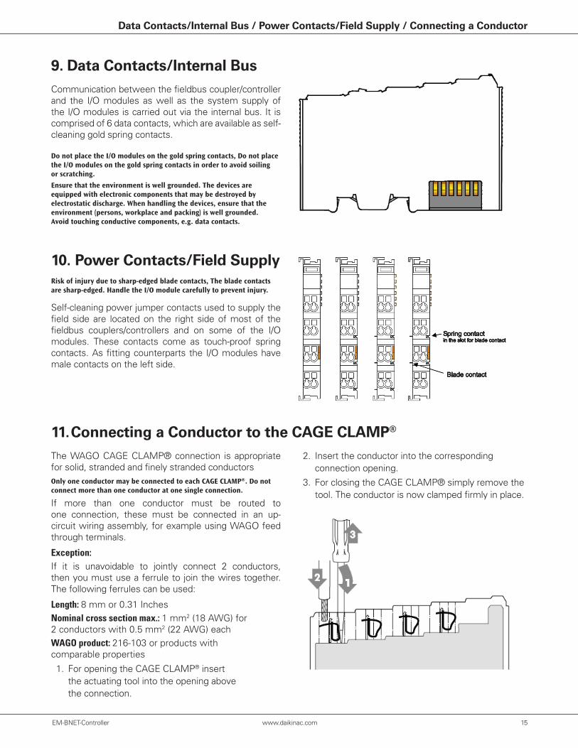
9. Data Contacts/Internal Bus
10. Power Contacts/Field Supply
Communication between the fieldbus coupler/controller and the I/O modules as well as the system supply of the I/O modules is carried out via the internal bus. It is comprised of 6 data contacts, which are available as self-cleaning gold spring contacts.
Self-cleaning power jumper contacts used to supply the field side are located on the right side of most of the fieldbus couplers/controllers and on some of the I/O modules. These contacts come as touch-proof spring contacts. As fitting counterparts the I/O modules have male contacts on the left side.
Do not place the I/O modules on the gold spring contacts, Do not place the I/O modules on the gold spring contacts in order to avoid soiling or scratching.
Ensure that the environment is well grounded. The devices are equipped with electronic components that may be destroyed by electrostatic discharge. When handling the devices, ensure that the environment (persons, workplace and packing) is well grounded. Avoid touching conductive components, e.g. data contacts.
Risk of injury due to sharp-edged blade contacts, The blade contacts are sharp-edged. Handle the I/O module carefully to prevent injury.
11. Connecting a Conductor to the CAGE CLAMP®
The WAGO CAGE CLAMP® connection is appropriate for solid, stranded and finely stranded conductorsOnly one conductor may be connected to each CAGE CLAMP®. Do not connect more than one conductor at one single connection.
If more than one conductor must be routed to one connection, these must be connected in an up- circuit wiring assembly, for example using WAGO feed through terminals.
Exception:If it is unavoidable to jointly connect 2 conductors, then you must use a ferrule to join the wires together. The following ferrules can be used:
Length: 8 mm or 0.31 InchesNominal cross section max.: 1 mm2 (18 AWG) for 2 conductors with 0.5 mm2 (22 AWG) each WAGO product: 216-103 or products with comparable properties
1. For opening the CAGE CLAMP® insert the actuating tool into the opening above the connection.
2. Insert the conductor into the corresponding connection opening.
3. For closing the CAGE CLAMP® simply remove the tool. The conductor is now clamped firmly in place.

16 www.daikinac.com EM-BNET-Controller EM-BNET-Controller www.daikinac.com PB
Our continuing commitment to quality products may mean a change in specifications without notice. © 2016 • Houston, Texas • Printed in the USA.
Notes