quick image series vision measuring system...stitching function • the newly-developed correction...
TRANSCRIPT

Visio
n M
easu
ring
Syst
em
Catalog No.E14009(2)
2-D Color Vision Measuring SystemQUICK IMAGE Series

2
Simple to operate and easy-to-perform measuring
Powerful backup for your quality control system
Reliability
Usability
Outstanding improvement in operational efficiency and productivity
Outstanding improvement
Efficiency
The 2-D measuring machine created with the ultimate Mitutoyo quality!
2-D Color Vision Measuring System
QUICK IMAGE Series

3
4
Powerful backup for your quality control system
Lets you perform measurement stable andhighly accurate measurements no matterwhere they are performed within the screen
Stable and highly accuratemeasurement of large workpieces
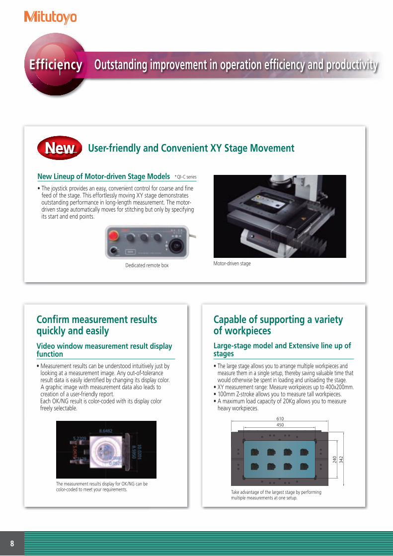
Gasket
Light alloy die-cast part
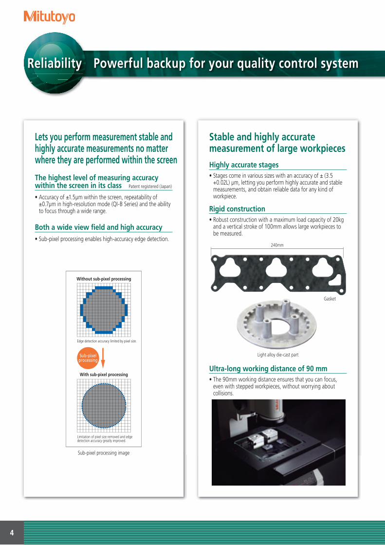
Without sub-pixel processing
Edge detection accuracy limited by pixel size.
Limitation of pixel size removed and edge detection accuracy greatly improved.
With sub-pixel processing
Sub-pixelprocessing
Sub-pixel processing image
The highest level of measuring accuracy within the screen in its class Patent registered (Japan)
• Accuracy of ±1.5µm within the screen, repeatability of ±0.7µm in high-resolution mode (QI-B Series) and the ability to focus through a wide range.
Highly accurate stages • Stages come in various sizes with an accuracy of ± (3.5
+0.02L) µm, letting you perform highly accurate and stable measurements, and obtain reliable data for any kind of workpiece.
Both a wide view field and high accuracy • Sub-pixel processing enables high-accuracy edge detection.
Rigid construction • Robust construction with a maximum load capacity of 20kg
and a vertical stroke of 100mm allows large workpieces to be measured.
Ultra-long working distance of 90 mm • The 90mm working distance ensures that you can focus,
even with stepped workpieces, without worrying about collisions.
Reliability
240mm

5
Human errors due to focusinghave been eliminated
Traceability to national standards
22mm
Measuring of a cylindrical workpiece
Measuring a stepped workpiece
Utilizes our in-house developed Telecentric Optical System Patent registered (Japan, the U.S.A. and Europe)
• Errors due to height are strictly minimized within a depth of focus with steps of up to 22mm, and measurements are possible in which human errors due to focusing are eliminated.
Mitutoyo...
Uses calibration artifacts traceable to national standards • Mitutoyo has a large collection of standard artifacts whose
dimensions are traceable to the national length standards of Japan. These artifacts are used to calibrate the specialized equipment used in the calibration of Mitutoyo's measuring tools and instruments, and so traceability to international length standards is established and maintained. Mitutoyo also provides the service of temperature calibration that is absolutely essential to high-accuracy length measurement.
National(Primary)Standard
(NMIJ, AIST)The atomic clock synchronized to UTC
National Metrology Institute of Japan, National Institute of Advanced Industrial Science and Technology
Secondary standard
Mitutoyo Metrological Standards Calibration Section
(JCSS Accredited Cal. Lab. No.0067)633nm Iodine Stabilized He-Ne Laser
Working standard
*This chart shows a simplified traceability system of QUICK IMAGE.
Standard scale
QUICK IMAGE
Mitutoyo Utsunomiya Calibration Center(JCSS Accredited Cal.Lab. No.0031)
633nm Stabilized He-Ne Laser
Mitutoyo Metrological Standards Calibration Section
(JCSS Accredited Cal. Lab. No.0067)Frequency Standard Oscillator

6
Simple to operate and easy-to-perform measuring
One-click circle tool One-click box tool
Correct measurement of a small feature is enabled by zooming in
Multiple view-field stitching image
Prompt measurement with the entire workpiece image on screen
New
Usability
Entire View of A Large Workpiece Drastically Improves Ease of Operation and Measurement Efficiency
Stitching Function• The newly-developed correction algorithm for use in stitching (multiple image-to-image
coupling) achieves high-accuracy measurement. The Stitching function enables a large workpiece that extends beyond the visual field to be measured with its entire image displayed. This allows quick identification of measured and unmeasured points at a glance.
After a stitching operation, measurement is speedily advanced without the need to move the stage.
Simple execution of multiple measurements
Easy-to-operate without the manual
One-click tool • With just one click, anyone can easily perform multiple
measurements. The outlier removal function automatically eliminates unnecessary measurement points, thus enabling accurate and stable multipoint measurement.
EZ mode Design application pending (Japan)
• This mode provides an operation guidance display to guide the operator even if it's their first time performing
measurements, so there is no need to keep referring to the instruction manual while working.

7
CAD user templateNote: QS-CAD I/F is required(available as an option).
User template
Enhanced rectangle template
Quick-release ring
Measurement finished
One-click
Automatic recognition
The position and inclination of a workpiece can be measured even if it has moved
Focusing in on a workpiece like the one shown above is unnecessary.
No troublesome positioning is required
Simple focusing
An intuitive OK/NG judgment ofmeasurement is possible
Capable of visually capturing an entire image
Perform quick measurements even on large workpieces
One-click execution function Patent pending (Japan)
• After placing the workpiece within the field of view, the machine automatically recognizes the position and angle using a pattern search function and then finishes the measurements. There is no need for positioning and axially-aligning the workpiece.
Wide focus range• Our specifically-designed optical system has achieved
the long focal depth of 22mm. This allows measurement virtually without the time-consuming focusing task, supporting an efficient measurement operation.
Template comparison test function• Use the function to compare workpieces against their
templates to enable OK/NG judgments to be made at a glance. The function lets you utilize any drawing and CAD model for templates, with the exception of standard templates.
Graphics function• The current position, coordinate system, measuring item and
measurement result are automatically displayed in a graphics window. The graphics window prevents omissions and errors with the measurements from occurring. 2-D CAD model data can be imported (optional) in order to better capture the actual full image.
Quick release mechanism on the XY stage *QI-A series, QI-B series
• Quick-release mechanisms are built into both fine feed controls on the XY stage.
• This allows the stage to be moved rapidly to bring the next measuring point into view no matter where it is on the workpiece.
8
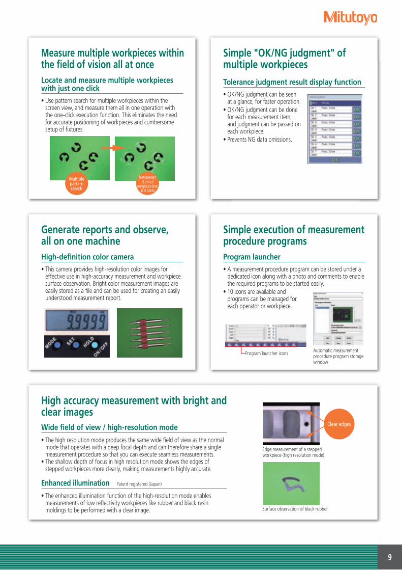
342
240
450610
Take advantage of the largest stage by performingmultiple measurements at one setup.
The measurement results display for OK/NG can be color-coded to meet your requirements.
User-friendly and Convenient XY Stage Movement
New Lineup of Motor-driven Stage Models * QI-C series
• The joystick provides an easy, convenient control for coarse and fine feed of the stage. This effortlessly moving XY stage demonstrates outstanding performance in long-length measurement. The motor-driven stage automatically moves for stitching but only by specifying its start and end points.
Motor-driven stageDedicated remote box
New
Outstanding improvement in operation efficiency and productivityEfficiency
Confirm measurement results quickly and easily
Capable of supporting a variety of workpieces
Video window measurement result display function • Measurement results can be understood intuitively just by
looking at a measurement image. Any out-of-tolerance result data is easily identified by changing its display color. A graphic image with measurement data also leads to creation of a user-friendly report.
Each OK/NG result is color-coded with its display color freely selectable.
Large-stage model and Extensive line up of stages
• The large stage allows you to arrange multiple workpieces and measure them in a single setup, thereby saving valuable time that would otherwise be spent in loading and unloading the stage.
• XY measurement range: Measure workpieces up to 400x200mm.• 100mm Z-stroke allows you to measure tall workpieces.• A maximum load capacity of 20Kg allows you to measure
heavy workpieces.
9
Surface observation of black rubber
Edge measurement of a stepped workpiece (high resolution mode)
Clear edges
Multiple pattern search
Measurement of several
workpieces done all at oncea
Simple "OK/NG judgment" of multiple workpieces
Simple execution of measurement procedure programs
Generate reports and observe, all on one machine
Measure multiple workpieces within the field of vision all at once
Tolerance judgment result display function• OK/NG judgment can be seen
at a glance, for faster operation.• OK/NG judgment can be done
for each measurement item, and judgment can be passed on each workpiece.
• Prevents NG data omissions.
Program launcher• A measurement procedure program can be stored under a
dedicated icon along with a photo and comments to enable the required programs to be started easily.
• 10 icons are available and programs can be managed for each operator or workpiece.
High-definition color camera• This camera provides high-resolution color images for
effective use in high-accuracy measurement and workpiece surface observation. Bright color measurement images are easily stored as a file and can be used for creating an easily understood measurement report.
Locate and measure multiple workpieces with just one click• Use pattern search for multiple workpieces within the
screen view, and measure them all in one operation with the one-click execution function. This eliminates the need for accurate positioning of workpieces and cumbersome setup of fixtures.
Automatic measurement procedure program storage window
Program launcher icons
High accuracy measurement with bright and clear imagesWide field of view / high-resolution mode
• The high resolution mode produces the same wide field of view as the normal mode that operates with a deep focal depth and can therefore share a single measurement procedure so that you can execute seamless measurements.
• The shallow depth of focus in high resolution mode shows the edges of stepped workpieces more clearly, making measurements highly accurate.
Enhanced illumination Patent registered (Japan)
• The enhanced illumination function of the high-resolution mode enables measurements of low reflectivity workpieces like rubber and black resin moldings to be performed with a clear image.
10
Progressive-die pressed parts
Measuring a tiny stepped workpiece
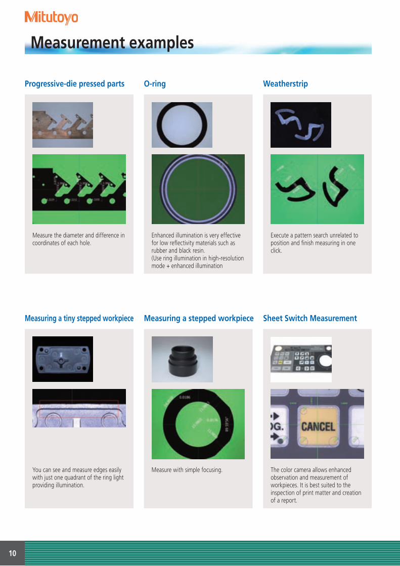
O-ring
Measuring a stepped workpiece
Weatherstrip
Sheet Switch Measurement
Measure the diameter and difference in coordinates of each hole.
You can see and measure edges easily with just one quadrant of the ring light providing illumination.
Enhanced illumination is very effective for low reflectivity materials such as rubber and black resin.(Use ring illumination in high-resolution mode + enhanced illumination
Measure with simple focusing.
Execute a pattern search unrelated to position and finish measuring in one click.
The color camera allows enhanced observation and measurement of workpieces. It is best suited to the inspection of print matter and creation of a report.
Measurement examples

11
QIPAK (two modes) enables quick and easy measurement
Powerful edge-detection functionality enables fast measurementOutlier removal
Auto trace tool
Dual-area contrast tool
Removes outliers caused by anomalies such as debris, burrs and chips.
Automatically detects the edges of unknown contours and obtains point group data.Point group data lets you perform contour form analysis and design value comparison using FORMTRACEPAK-AP (optional).
Automatically sets the amount of illumination so that the contrast between two regions is maximized.Users can also set the optimum intensity to suit the workpiece.
EZ mode(Simple measurement mode)
PRO mode(General purpose measurement mode)
Simple execution and editing of programsSmart editorThis function allows XY-stage target position, illumination condition, etc., to be separately displayed as icons or labels in the list of part programs(automatic measurement procedure programs), thereby simplifying program editing.
Editing an illumination condition according to the dialog
Editing a circle tool on the video window
Editing design values and tolerances according to the dialog
Standard software QIPAK

12
Early detection of process irregularitiesCentralized process management software: MeasurLinkStatistical data can be displayed in real-time, making early detection of process irregularities possible. Early identification of an out-of-control situation enables rapid remedial action to be taken when necessary.
Examples of remedial action• Mold repair or cycle-timing change• Cutting tool adjustment or replacement
Effective use of CAD modelMeasurement support software: QS-CAD I/F2-D CAD model data (DXF-, or IGES-formatted) can be imported into QIPAK. Conversely, QIPAK measurement results can be converted into 2-D CAD model data. The design value for each measurement item is automatically entered. Since the graphics window makes the present location easy to identify, the operator can quickly move the stage a given point in the 2D CAD model.
Easily handle sophisticated dimension and contour evaluations
• A contour measurement is easy to make. Perform contour matching against the design value data.• You can define virtual circles of a given diameter enabling over-pin diameter analysis to be performed.
Contour evaluation and analysis software: FORMTRACEPAK-APData processing software for advanced form analysis that carefully reads point group date acquired via tools such as the auto trace tool.
Example of gear contour matching, and an over-pin diameter analysis
Table
Order No.: 02ATE760Dimensions: 1800(W)×900(D)×740(H)mmMass: 60kg
Foot switch
Standard typeOrder No.: 937179T
Rigid typeOrder No.: 12AAJ088
Stage adapter sets
V-block with clamp Swivel center supportHolder with clamp
Order No.: 172-378 Max. supportable diameter: ø25mm Center height from mounting face: 38-48mmDimensions: 117(H)×90(W)×45(D)mmMass: 0.8kg
Note: An adapter set is required.
Order No.: 172-197 Can be set to an inclination angle of ±10°, in minimum increments of 1°Max. supportable dimensions: When horizontally positioned: ø80×140mm When tilted at 10°angle: ø65×140mmMass: 2.5kg
Note: An adapter set is required.
Order No.: 176-107Maximum clamp length: 35mmDimensions: 62(H)×152(W)×38(D)mmMass: 0.4kg
Note: An adapter set is required.
Stage size10102010
201730174020
176-304 Stage adapter ̶ ○176-310 Stage adapter B ○ ̶
Note: One set consists of two adapters.
107.5
900
685
15801800
30
740
30
60
ø89.1
2843
0
Clamping of thin workpieces such as PCBs and pressed parts.
Clamping of cylindrical objects
Quick data entry while gripping the handle.
These are used when connecting some optional peripherals to the measuring device.
Clamping of the workpiece between centers for effective thread diameter and depth measurements.
Optional accessories
Order No.: Stage adapter : 176-304 Stage adapter B : 176-310Dimensions (1piece): 50(W)×340(D)×15(H)mm Note: The stage adapter B is 280(D).Mass: Stage adapter: 1.5Kg Stage adapter B: 1.2Kg
13
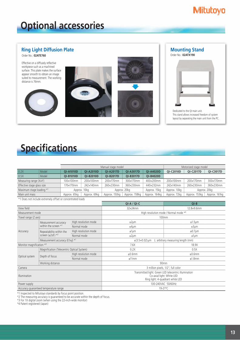
Dedicated to the QI main unit.This stand allows increased freedom of system layout by separating the main unit from the PC.
Manual stage model Motorized stage model0.2X Model QI-A1010D QI-A2010D QI-A2017D QI-A3017D QI-A4020D QI-C2010D QI-C2017D QI-C3017D0.5X Model QI-B1010D QI-B2010D QI-B2017D QI-B3017D QI-B4020DMeasuring range (X×Y) 100×100mm 200×100mm 200×170mm 300×170mm 400×200mm 200×100mm 200×170mm 300×170mmEffective stage glass size 170×170mm 242×140mm 260×230mm 360×230mm 440×232mm 242×140mm 260×230mm 360×230mmMaximum stage loading *1 Approx. 10kg Approx. 20kg Approx. 15kg Approx. 10kg Approx. 20kgMain unit mass Approx. 65kg Approx. 69kg Approx. 150kg Approx. 158kg Approx. 164kg Approx. 72kg Approx. 153kg Approx. 161kg
*1 Does not include extremely offset or concentrated loadsQI-A / QI-C QI-B
View fi eld 32×24mm 12.8×9.6mmMeasurement mode High resolution mode / Normal mode *4
Travel range (Z axis) 100mm
Accuracy
Measurement accuracy within the screen *1
High resolution mode ±2µm ±1.5µmNormal mode ±4µm ±3µm
Repeatability within the screen (±2σ) *2
High resolution mode ±1µm ±0.7µmNormal mode ±2µm ±1µm
Measurement accuracy (E1xy) *1 ±(3.5+0.02) µm L: arbitrary measuring length (mm)Monitor magnifi cation *3 7.6X 18.9X
Optical system
Magnifi cation (Telecentric Optical System) 0.2X 0.5X
Depth of focus High resolution mode ±0.6mm ±0.6mmNormal mode ±11mm ±1.8mm
Working distance 90mmCamera 3 million pixels, 1/2", full color
IlluminationTransmitted light: Green LED telecentric illumination
Co-axial light: White LEDRing light: 4-quadrant white LED
Power supply 100-240VAC 50/60HzAccuracy guaranteed temperature range 19-21ºC
*1 Inspected to Mitutoyo standards by focus point position.*2 The measuring accuracy is guaranteed to be accurate within the depth of focus.*3 For 1X digital zoom (when using the 22-inch-wide monitor)*4 Patent registered (Japan)
Optional accessories
Specifications
Ring Light Diffusion Plate Mounting Stand Order No.: 02ATX190
Effective on a diffusely reflective workpiece such as a machined surface. This plate makes the surface appear smooth to obtain an image suited to measurement. The working distance is 76mm.
Order No.: 02ATE760

14
(332) (478.5) (268.5)(979.5)
1784
9.5
872.5*125* 271.5*360 161.5* 90621
247
9079
339
.5
756.5
80 1625527012 12168168
(768.5)
(127.5)(177.5)(110.5)
12168
534
801
711.5*53.5* 120.5*360
70.5* 90551
9019
8.5
106
1767
8
110 1621521012 168
(768.5)(127.5)(282.5)(195.5) 624
70.5* 551 90
807
711.5*88.5* 175.5*360
9020
4.5
112
1767
8
110 1621521012 12168168
(132)(277.5) (231.5)
(942.5)857.5*
247
90
849.
5
101.5 170.5*360 146.5* 90621
39.5
1779
3
25* 555
80 1625527012 12168168
(232)(377.5) (231.5)
(942.5)
101.5
849.
5
90
857.5*
360 220.5* 146.5* 90621
247
1739
.579
3
75*655
80 1625527012 12168168
Manual stage model
QI-A1010D/B1010D QI-A2010D/B2010D
Unit: mm
QI-A3017D/B3017D
QI-A4020D/B4020D
QI-A2017D/B2017D
QI-A seriesQI-B seriesQI-A4020DManual stage modelThe mounting stand (02ATX190) is optional.
* Varies depending on position of XY stage. Values in parentheses indicate maximum size.
QI-A seriesQI-B seriesQI-A4020DManual stage modelThe mounting stand (02ATX190) is optional.
Dimensions chart

15
(208)(193)86*
547 650
807
17360 101* 9 90551
204.
590
112
678
12 12168168 215 16110 210
(133)(132)
(240)(844)
11051825* 759*
849.
5
133*360 48* 90621
247
9017
39.5
793
12 12168168 80 16255270
(232)(340) (133)
(844)
48*759*
849.
5
110 183*360 621 90
247
9017
39.5
793
75*653
12 12168168 80 16255270
Motorized stage modelUnit: mm
QI-C2010D QI-C2017D
QI-C3017D
The mounting stand (02ATX190) is optional.
* Varies depending on position of XY stage. Values in parentheses indicate maximum size.
QI-C seriesQI-C2017DMotorized stage modelThe mounting stand (02ATX190) is optional.
QI-C seriesQI-C2017DMotorized stage model
072
1804
(2)A
-(CH)
NE, P
rinte
d in
Japa
n
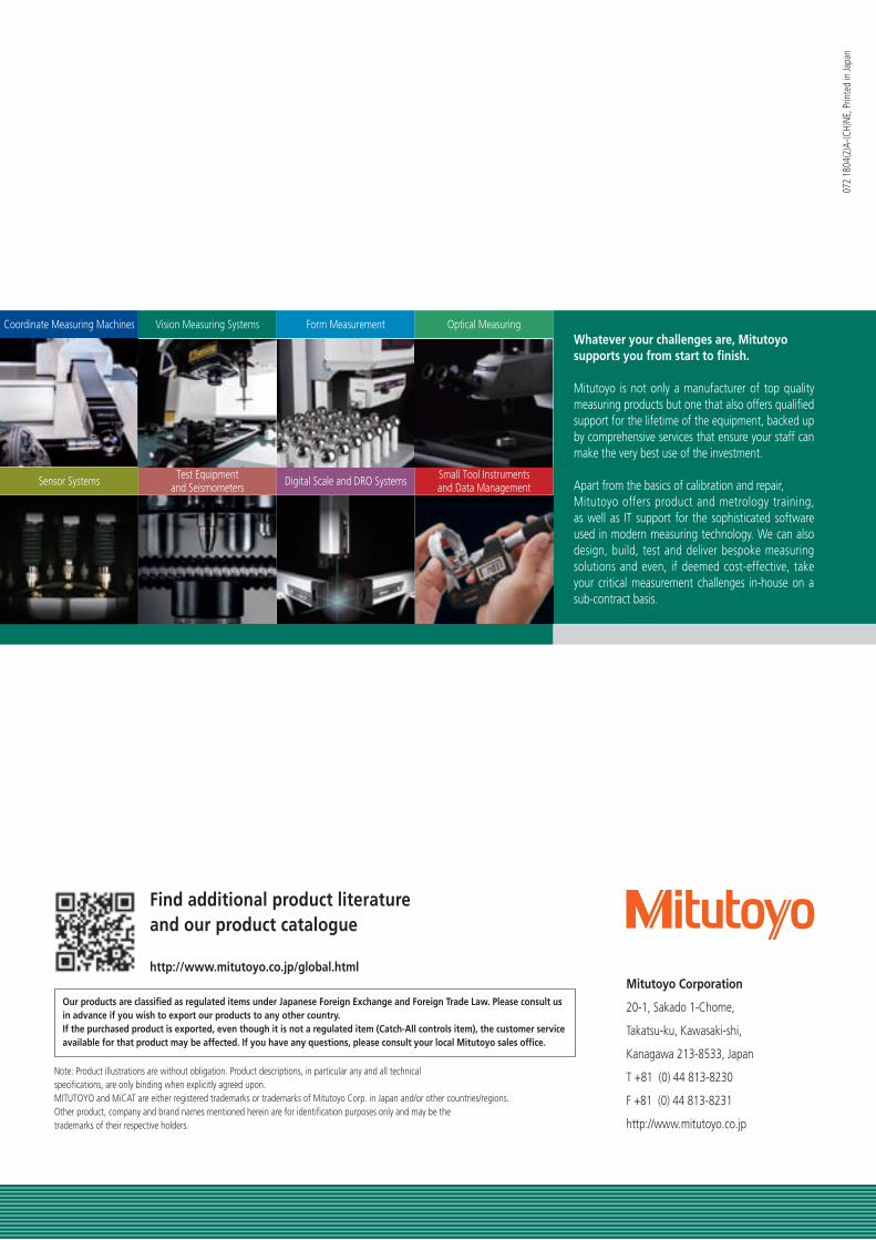
Coordinate Measuring Machines
Sensor Systems
Vision Measuring Systems
Test Equipmentand Seismometers
Form Measurement
Digital Scale and DRO Systems
Optical Measuring
Small Tool Instrumentsand Data Management
http://www.mitutoyo.co.jp/global.html
Find additional product literature and our product catalogue
Mitutoyo Corporation
20-1, Sakado 1-Chome,
Takatsu-ku, Kawasaki-shi,
Kanagawa 213-8533, Japan
T +81 (0) 44 813-8230
F +81 (0) 44 813-8231
http://www.mitutoyo.co.jp
Whatever your challenges are, Mitutoyo supports you from start to finish.
Mitutoyo is not only a manufacturer of top quality measuring products but one that also offers qualified support for the lifetime of the equipment, backed up by comprehensive services that ensure your staff can make the very best use of the investment.
Apart from the basics of calibration and repair, Mitutoyo offers product and metrology training, as well as IT support for the sophisticated software used in modern measuring technology. We can also design, build, test and deliver bespoke measuring solutions and even, if deemed cost-effective, take your critical measurement challenges in-house on a sub-contract basis.
Note: Product illustrations are without obligation. Product descriptions, in particular any and all technical specifications, are only binding when explicitly agreed upon.MITUTOYO and MiCAT are either registered trademarks or trademarks of Mitutoyo Corp. in Japan and/or other countries/regions. Other product, company and brand names mentioned herein are for identification purposes only and may be the trademarks of their respective holders.
Our products are classified as regulated items under Japanese Foreign Exchange and Foreign Trade Law. Please consult us in advance if you wish to export our products to any other country.If the purchased product is exported, even though it is not a regulated item (Catch-All controls item), the customer service available for that product may be affected. If you have any questions, please consult your local Mitutoyo sales office.