quick action couplings - safeway hyd · pdf filewarning statement safety guide — quick...
TRANSCRIPT

q u i c k a c t i o n c o u p l i n g sreplacement and Unique o eM Des igns
Made in the USa
warning statement
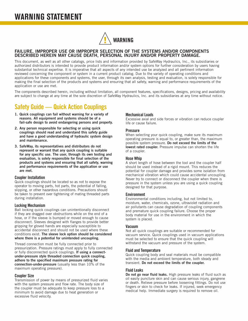
Safety Guide — Quick Action Couplings1. Quick couplings can fail without warning for a variety of
reasons. All equipment and systems should be of a fail-safe design to avoid endangering persons and property.
2. Any person responsible for selecting or using quick couplings should read and understand this safety guide and have a good understanding of hydraulic system design and maintenance.
3. SafeWay, its representatives and distributors do not represent or warrant that any quick coupling is suitable for any specific use. The user, through its own testing and evaluation, is solely responsible for final selection of the products and systems and ensuring that all safety, warning and performance requirements of the application or use are met.
Coupler Installation Quick couplings should be located so as not to expose the operator to moving parts, hot parts, the potential of falling, slipping, or other hazardous conditions. Precautions should be taken to prevent over tightening of mating threaded parts during installation.
Locking Mechanism Ball locking quick couplings can unintentionally disconnect if they are dragged over obstructions while on the end of a hose, or if the sleeve is bumped or moved enough to cause disconnect. Sleeves designed with flanges to provide better gripping for gloved hands are especially susceptible to accidental disconnect and should not be used where these conditions exist. The sleeve lock option should be considered where there is a potential for unintended uncoupling.
Thread connection must be fully connected prior to pressurization. Pressure ratings must apply to fully connected or fully disconnected quick couplings. If using a connect-under-pressure style threaded connection quick coupling, adhere to the specified maximum pressure rating for connection-under-pressure (usually less than 10% of the maximum operating pressure).
Coupler Size Transmission of power by means of pressurized fluid varies with the system pressure and flow rate. The body size of the coupler must be adequate to keep pressure loss to a minimum to avoid damage due to heat generation or excessive fluid velocity.
Mechanical Loads Excessive axial and side forces or vibration can reduce coupler life or cause failure.
Pressure When selecting your quick coupling, make sure its maximum operating pressure is equal to, or greater than, the maximum possible system pressure. Do not exceed the limits of the lowest rated coupler. Pressure impulse can shorten the life of a coupler.
Hose Whip A short length of hose between the tool and the coupler half should be used instead of a rigid mount. This reduces the potential for coupler damage and provides some isolation from mechanical vibration which could cause accidental uncoupling. Never try to connect or disconnect the coupler when there is pressure in the system unless you are using a quick coupling designed for that purpose.
Environment Environmental conditions including, but not limited to, moisture, water, chemicals, ozone, ultraviolet radiation and air pollutants can cause degradation of coupling components and premature quick coupling failure. Choose the proper body material for use in the environment in which the system is placed.
Vacuum Not all quick couplings are suitable or recommended for vacuum service. Quick couplings used in vacuum applications must be selected to ensure that the quick coupling will withstand the vacuum and pressure of the system.
Fluid and Temperature Quick coupling body and seal materials must be compatible with the media and ambient temperature, both steady and transient. Do not exceed the limits of the coupler.
Fluid Leaks Do not go near fluid leaks. High pressure leaks of fluid such as oil easily puncture skin and can cause serious injury, gangrene or death. Relieve pressure before loosening fittings. Do not use fingers or skin to check for leaks. If injured, seek emergency medical help. Immediate surgery is required to remove oil.
FAIlure, Improper uSe or Improper SelecTIon oF The SySTemS AnD/or componenTS DeScrIbeD hereIn mAy cAuSe DeATh, perSonAl Injury AnD/or properTy DAmAge.This document, as well as all other catalogs, price lists and information provided by SafeWay Hydraulics, Inc., its subsidiaries or authorized distributors is intended to provide product information and/or system options for further consideration by users having substantial technical expertise. It is imperative that all aspects of any intended use be analyzed and all pertinent information reviewed concerning the component or system in a current product catalog. Due to the variety of operating conditions and applications for these components and systems, the user, through its own analysis, testing and evaluation, is solely responsible for making the final selection of the products and systems and ensuring that all safety, warning and performance requirements of the application or use are met.
The components described herein, including without limitation, all component features, specifications, designs, pricing and availability are subject to change at any time at the sole discretion of SafeWay Hydraulics, Inc. and its subsidiaries at any time without notice.
! WARNING

TABL
E OF
CON
TENT
S
taBLe OF COntents
Custom Capabilities . . . . . . . . . 3
Sales Aids . . . . . . . . . . . . . . . . . 4 Literature & Advertising, Packaging Options
Industry Application Symbols . 5
Ordering Information . . . . . . . . 5
Product Overview . . . . . . . . . . . 6
S10 Series . . . . . . . . . . . . . . . .7-8 General Purpose Industrial Interchange (Steel, Brass, 303 Stainless)
SH20 Series . . . . . . . . . . . . . .9-10 General Purpose Bruning SM Series Interchange (Steel)
S30 Series . . . . . . . . . . . . . .11-12 Screw Together, High Pressure for Portable Hydraulic Rams (Steel)
S51 Series . . . . . . . . . . . . . .13-14 Screw Together, Maximum Flow with Minimum Spillage (Brass & Steel)
S56 Series . . . . . . . . . . . . . .15-16 Compact Design, High Flow, High Working Pressure (Steel)
FF49 Series . . . . . . . . . . . . .17-18 High Pressure & High Flow Without Spillage (Steel & 303 Stainless)
FFE49 Series . . . . . . . . . . . .19-20 Flush Face, Non-Spill (Steel)
PRODUCT PAGES PRODUCT PAGES
FFEC49 Series . . . . . . . . . . . . . 21 Flush Face, Non-Spill, Connect-Under-Pressure (Steel)
FDB49 Series . . . . . . . . . . . . . . 22 Flush Face, Non-Spill, Hansen DB Series Interchange (316 Stainless)
S20 Series . . . . . . . . . . . . . .23-24 General Purpose Agriculture O.E.M. Couplings (Steel)
S40 Series . . . . . . . . . . . . . .25-26 One-Hand Operation, Agriculture O.E.M. Couplings (Steel)
S70 Series . . . . . . . . . . . . . .27-28 Flowmaster® Connect-Under-Pressure, Agriculture O.E.M. Couplings (Steel)
ISO Agriculture Tips . . . . . . . . 29 Ball Valve and Poppet Valve Models (Steel)
Agriculture O .E .M . . . . . . . . . . . 29 Previous Designs (Steel)
Coupler Adapters . . . . . . . . . . 30 Interconnect Non-Compatible Bodies & Tips (Steel)
S80 & S82 Series . . . . . . . . . . 31 Pneumatic Interchange
Accessories . . . . . . . . . . . . .32-33 Dust Caps & Dust Plugs, Break-Away Clamps, Replacement Seals, Repair Kits, Reducer Bushings
Notes . . . . . . . . . . . . . . . . . . . . 34
Q u i C k a C t i O n C O u p L i n g s , a d a p t e r s & a C C e s s O r i e s
Saf
eWay
MAD
E IN
USAS
afeWay
MAD
E IN U
SA
Saf
eWay
USA
SAFEWAY
SAFEWAY
Saf
eWay
USA
Saf
eWay
USA
Saf
eWay
USA
Saf
eWay
USA
CO
NN
ECTED
SafeW
ay US
A
Saf
eWay
US
A
Saf
eWay
USA
Saf
eWay
USA
Saf
eWay
USA
MAD
E IN U
SAS
afeWay S
afeW
ay
MAD
E IN
USA
Safe
Way
USA
Safe
Way
USASafeW
ay USA

3
Custom CapabilitiesF O C u s O n O r i g i n a L e Q u i p m e n t m a n u F a C t u r e r s
SafeWay will partner with you to develop custom solutions when standard quick coupling products do not meet your unique feature or mounting requirement, and when you need a distinct marketing advantage. We work with various styles, materials and sizes to meet the demands of your unique application to set you apart in the market-place. Please contact the factory to discuss your custom requirements.
CURRENT CUSTOM RANGE INCLUDES:■ general purpose quick action couplings.■ Stab applications – held together by mechanical means.■ non-spill cartridges for custom castings.■ connect-under-pressure.
CUST
OM C
APAB
ILIT
IES
All oF SAFeWAy hyDrAulIcS' proDucTS Are DeSIgneD, mAchIneD & ASSembleD In The uSA.
w w w . s a f e w a y h y d . c o m | 4 0 4 0 n o r e x d r i v e | c h a s k a , m n 5 5 3 1 8 | 8 0 0 . 2 2 2 . 1 1 6 94
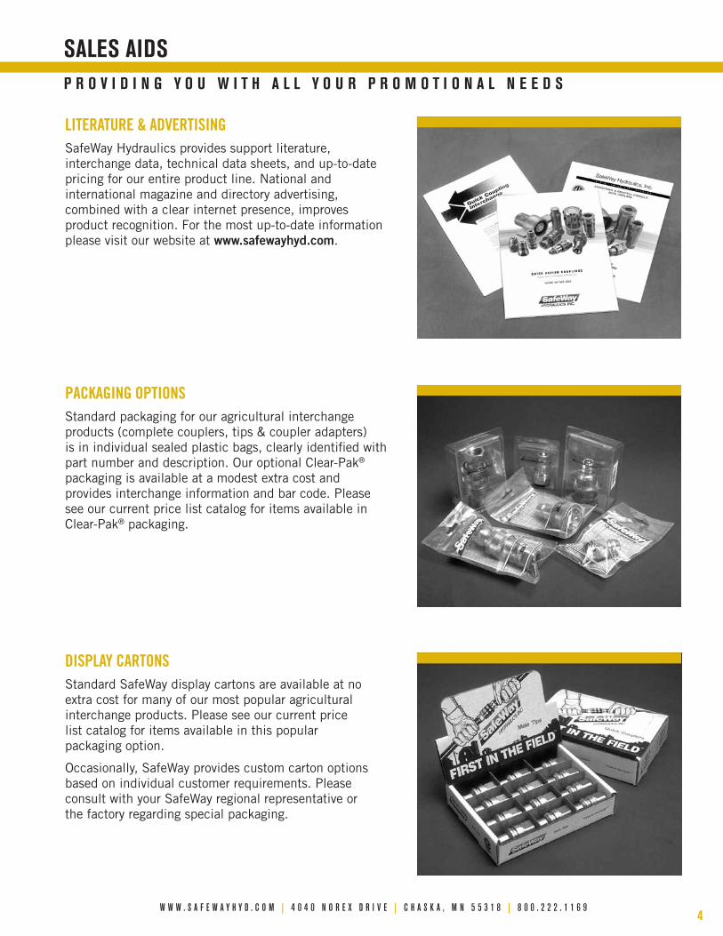
LITERATURE & ADVERTISINGSafeWay Hydraulics provides support literature, interchange data, technical data sheets, and up-to-date pricing for our entire product line. National and international magazine and directory advertising, combined with a clear internet presence, improves product recognition. For the most up-to-date information please visit our website at www.safewayhyd.com.
PACkAGING OPTIONSStandard packaging for our agricultural interchange products (complete couplers, tips & coupler adapters) is in individual sealed plastic bags, clearly identified with part number and description. Our optional Clear-Pak® packaging is available at a modest extra cost and provides interchange information and bar code. Please see our current price list catalog for items available in Clear-Pak® packaging.
DISPLAy CARTONSStandard SafeWay display cartons are available at no extra cost for many of our most popular agricultural interchange products. Please see our current price list catalog for items available in this popular packaging option.
Occasionally, SafeWay provides custom carton options based on individual customer requirements. Please consult with your SafeWay regional representative or the factory regarding special packaging.
p r O v i d i n g Y O u w i t h a L L Y O u r p r O m O t i O n a L n e e d s
saLes aids

5
INDU
STRy
SyM
BOLS
industrY appLiCatiOn sYmBOLs
Ordering inFOrmatiOn
Application symbols indicate which industry a coupling is typically used in. Although, all couplings can be used in any industry, provided they meet existing application requirements.
transpOrtatiOn utiLitYOiL & gas resCue eQuipment
marine & deFense mediCaL miCrOwave
water
industriaL pLants
hYdrauLiC JaCks
maintenanCe & repair OperatiOns
FOOd & Beverage
FOrestrYChemiCaL prOCessing
COnstruCtiOn
agriCuLtureaerOspaCe
When orDerIng SAFeWAy proDucTS pleASe noTe The FolloWIng:
1. catalog number. Nearly all SafeWay quick couplers can be ordered as a complete coupling (male tip half and female body half connected) or as a separate male tip half and female body half. Part numbers are listed in this catalog and in the SafeWay price list.
2. note options or Special requirements. Many of SafeWay’s products are available with off-the-shelf options, such as special O-ring compounds for media compatibility and sleeve-lock to prevent accidental disconnection. Please provide the option number and description when placing your order. Do not hesitate to consult with your SafeWay Distributor or the factory about standard and special order options. They will be happy to assist you.
3. Actual Quantity. When placing your order, please provide individual part number quantity, not number of boxes, packages or master cartons.
exAmple oF hoW To SpecIFy SpecIAl FeATureS AnD SeAl coDeS:
Sxxxx-x-xx-x
PART NUMBERFEATURE CODENone = NoneSleeve Lock = SLNo Valving = NV
SEAL CODENone = Nitrile (Buna-N)Ethylene Propylene = EFlorocarbon (Viton®) = FNeoprene = NViton® is a registered trademark of DuPont Dow Elastomers.

w w w . s a f e w a y h y d . c o m | 4 0 4 0 n o r e x d r i v e | c h a s k a , m n 5 5 3 1 8 | 8 0 0 . 2 2 2 . 1 1 6 96
nOtes: (1) Special low temperature Viton® seals are standard (-40˚ to +482˚ F). (2) S51 Series is available in brass or electroless nickel plated steel (-STL). Both include brass valving & ductile cast iron wing nut or steel hex nut. (3) Varies by body size — consult catalog, SafeWay's website or factory regarding specific applications. (4) Consult catalog or SafeWay website for available Pipe Thread, O-ring Boss (ORB), BSPP and Metric sizes. (5) The FF49, SF49, FFE49 and FFEC49 Series meet the dimensional requirements of Industry Standard ISO 16028. (6) Consult interchange catalog, SafeWay website or the factory for specific interchange details.disclaimer: Interchange information is based on SafeWay products that interconnect due to dimensional compatibility. It does not take into account substantial differences in maximum operating psi and performance between brands or specific features unique to a given brand. Product part numbers and specifications change frequently. Please consult SafeWay’s website (www.safewayhyd.com) or Customer Service regarding interchangeability and technical information.
Viton® is a registered trademark of DuPont Dow Elastomers.
prOduCt OverviewFeatures prOduCts
s10 series s20 series sh20 series s30 series s40 series s51 series s56 series s70 series FF49 series sF49 series FFe49 series FFeC49 series FdB49 series
page numbers 7-8 23-24 9-10 11-12 25-26 13-14 15-16 27-28 17-18 17-18 19-20 21 22
COnstruCtiOnPlated Steel ✔ ✔ ✔ ✔ ✔ ✔ Comb (2) ✔ ✔ ✔ ✔ ✔
Stainless Steel (303) (303) (316L)
Brass ✔ ✔ Comb (2)
Standard Buna-N Seals (-40˚ to +250˚ F) ✔ ✔ ✔ ✔ ✔ ✔ ✔ ✔ ✔ ✔ ✔
Viton® (F) Seals (-15˚ to +450˚ F) (Option) (Option) (Option) (Option) (Option) (Option) (Option) (Option) (Option) ✔ (Option) (Option) ✔ (1)
EPR (E) Seals (-70˚ to +300˚ F) (Option) (Option) (Option) (Option) (Option) (Option) (Option) (Option) (Option) (Option) (Option) (Option)
Other Seal Options ✔ ✔ ✔ ✔ ✔ ✔ ✔ ✔ ✔ ✔ ✔
Flush-Face Design ✔ (5) ✔ (5) ✔ (5) ✔ (5) ✔
Screw-Together (Thread to Connect) ✔ ✔
Wing Nut or Hex Nut Sleeve ✔
Two-Way Sleeve (Push-Pull) ✔ ✔
Sleeve Lock (SL) (Option) (Option) ✔ ✔ (Option)
perFOrmanCe (Consult specifications for details) nOte: k = 1,000 psi
Maximum Operating Pressure (PSI)
Steel 3K-5K 3K-4K 6K 10K 3K-4K 2.5K-3K 4K-5K 3K 6K-10K 3K-5K 4K
Stainless Steel 2K-5K 3K 1.4K-2K
Brass 1.6K-4K
NFPA Rated Flow (GPM) (3) 0.8-50 3-50 3 3-6 3-12 12-76 3-50 12 10-12 10 3-50 12 50
avaiLaBLe BOdY size std. threads
1/8"Pipe Thread (4) ✔
O-ring Boss (4)
1/4"Pipe Thread (4) ✔ ✔ ✔ ✔ ✔ ✔ ✔
O-ring Boss (4) ✔ ✔
3/8"
Pipe Thread (4) ✔ ✔ ✔ ✔ ✔ ✔ ✔ ✔
O-ring Boss (4) ✔ ✔ ✔
Metric Thread (4) ✔
BSPP Thread (4) ✔
1/2"
Pipe Thread (4) ✔ ✔ ✔ ✔ ✔ ✔ ✔ ✔ ✔
O-ring Boss (4) ✔ ✔ ✔ ✔ ✔ ✔
BSPP Thread (4) ✔ ✔ ✔
3/4"Pipe Thread (4) ✔ ✔ ✔ ✔ ✔ ✔ ✔
O-ring Boss (4) ✔ ✔ ✔ ✔
1"Pipe Thread (4) ✔ ✔ ✔ ✔ ✔ ✔
O-ring Boss (4) ✔ ✔ ✔
1-1/4"Pipe Thread (4) ✔ ✔
O-ring Boss (4)
interChangeaBLe with: (6)Aeroquip FD45 FD42 FD48 FD31 FD71 FD51 5600 FD72 FD49 FD89-2000 FD89
Dixon (Perfecting) H AG T AG W K ST HT
Enerpac/Power Team C-604/9795 9794 (PT)
Faster Series HNV NV/NS PVVM NS/PV FB NV/ANV 4SFPV 2FFN 2FFN 2FFI 3FFI
Hansen Series HK WA56000 96 HA15000 QA29000 FF DB
Holmbury Series IB DIN PS P IA HQ HSS HQ HCP
Parker/Pioneer 60 4000 SM 3000 4200 6100 6600 8200 FF/FEM FS FEM FEC
Snap-Tite Series 72 60/61 76 60/61DC8 78 61 68C8 74 74 CP74

7
■ meets dimensional requirements of ISo 7241-1 Series b, the most widely used Industrial Interchange.
■ Available in body sizes from 1/8" to 1" with pipe thread and SAe o-ring boss (orb) standard.
■ Standard materials are steel, 303 stainless steel and brass. When ordering please add a prefix for either stainless steel or brass. example: S105-2 becomes SS105-2 in stainless steel and bS105-2 in brass.
■ Interchangeable half-for-half with Aeroquip FD45, hansen hK, and parker 60 Series as well as others conforming to this interchange.
■ Double shut-off poppet style valving with captive poppet seal provides a durable, guaranteed leak-free seal.
■ Full-flow design for optimum system performance.
■ All S10 Series quick couplings are 100% leak tested.
■ heavy-duty detent ball latch design for a reliable connection time after time.
■ Steel products feature rohS compliant plated surfaces (silver appearance).
■ Seals for most fluids available upon request.
■ only rugged, high quality carbon steel valving and retainers; no powdered metal parts.
■ brass and stainless steel S10 Series couplers are supplied with hardened stainless steel locking detent balls, poppet valve springs and retaining rings for increased corrosion resistance.
■ Sleeve lock, one-way shut-off, and straight-thru designs are available.
■ heavy-duty steel dust caps and dust plugs are available for the male tip halves and female body halves.
■ Field repair kits are available for 3/4" and 1" couplers in all materials and o-ring compounds.
■ method of obtaining and presenting performance data conforms to AnSI (nFpA) T3.20.2.r2, Hydraulic fluid power - Quick action couplings - Test methods.
steeL part numBers desCriptiOn maximum Operating pressure nFpa rated FLOw
Complete Coupler
Female Body half
maletip half
Body size
thread size and description
steel (s) stainless (ss) Brass (Bs)
psi (Bar) psi (Bar) psi (Bar) gpm (Lpm)
S10-1 S105-1 S101-1 1/8" 1/8" Female Pipe 5,000 (345) 5,000 (345) 3,000 (207) 0.8 (3)
S10-2 S105-2 S101-2 1/4" 1/4" Female Pipe 5,000 (345) 5,000 (345) 4,000 (276) 3 (12)
S10-2-6 S105-2-6 S101-2-6 1/4" 9/16"-18 Female ORB 5,000 (345) 5,000 (345) 4,000 (276) 3 (12)
S10-3 S105-3 S101-3 3/8" 3/8" Female Pipe 4,000 (276) 5,000 (345) 3,000 (207) 6 (23)
S10-3-8 S105-3-8 S101-3-8 3/8" 3/4"-16 Female ORB 4,000 (276) 5,000 (345) 3,000 (207) 6 (23)
S10-4 S105-4 S101-4 1/2" 1/2" Female Pipe 4,000 (276) 5,000 (345) 3,500 (241) 12 (45)
S10-4-10 S105-4-10 S101-4-10 1/2" 7/8"-14 Female ORB 4,000 (276) 5,000 (345) 3,500 (241) 12 (45)
S10-6 S105-6 S101-6 3/4" 3/4" Female Pipe 3,500 (241) 3,000 (207) 2,300 (159) 28 (106)
S10-6-12 S105-6-12 S101-6-12 3/4" 1-1/16"-12 Female ORB 3,500 (241) 3,000 (207) 2,300 (159) 28 (106)
S10-8 S105-8 S101-8 1" 1" Female Pipe 3,000 (207) 2,000 (138) 1,600 (110) 50 (189)
S10-8-16 S105-8-16 S101-8-16 1" 1-5/16"-12 Female ORB 3,000 (207) 2,000 (138) 1,600 (110) 50 (189)
Temperature Range: Standard Seals (Buna-N) -40° to +250° F Viton® Option -15° to +450° F EPR Option -70° to +300° F Other Seals Available.Vacuum Data: 27.4 inches Hg. both connected and disconnected — all sizes.
pressure rating (max. Operating pressure) is based on non-pulsating, Low Cycle applications with essentially steady pressure during the operating cycle. please consult factory regarding other applications.
Q u i C k C O u p L e r s i n h a r d e n e d s t e e L , 3 0 3 s t a i n L e s s s t e e L & B r a s s
SafeWay’s S10 Series is a general purpose, double shut-off quick coupling capable of containing a wide variety of fluids. primarily used for the transfer of hydraulic fluid, they can also be used with water, steam, chemicals and some gases. Widely used in both stationary and mobile industrial applications.
S10 Series
perFOrmanCe data
Viton® is a registered trademark of DuPont Dow Elastomers.

w w w . s a f e w a y h y d . c o m | 4 0 4 0 n o r e x d r i v e | c h a s k a , m n 5 5 3 1 8 | 8 0 0 . 2 2 2 . 1 1 6 98
PRESSURE DROP VS. FLOW S10 Series
FLOW (GPM)
PRES
SURE
DRO
P (P
SID)
1 .8 .6 .5 2 3 4 5 6 8 10 20 30 40 50 60 80 100
1
2
3
4 5 6
8 10
20
30
40 50 60
80 100
MIL-H-5606 OIL 100˚ F
= RATED FLOW
1/8"
1/4"
3/8"
1/2"
3/4"
1"
generaL purpOse industriaL interChange QuiCk COupLings
Saf
eWay
USA
E
D
B
G
H
F
C
TIP BODY
Saf
eWay
USA
ACONNECTED
Saf
eWay
USA
E
D
B
G
H
F
C
TIP BODY
Saf
eWay
USA
ACONNECTED
Saf
eWay
USA
E
D
B
G
H
F
C
TIP BODY
Saf
eWay
USA
ACONNECTED
dimensiOns (inches)
Complete Coupler number
Overall Length Body Length diameter wrench Flat diameter tip Length diameter hex
a B C d e F g h
S10-1 2.32 1.89 .93 .56 .66 1.25 .65 .56
S10-2 2.78 2.23 1.14 .75 .88 1.52 .86 .75
S10-2-6 2.90 2.29 1.14 .87 .97 1.58 1.01 .88
S10-3 3.03 2.48 1.39 .87 1.00 1.68 1.01 .88
S10-3-8 3.43 2.68 1.39 1.00 1.22 1.88 1.15 1.00
S10-4 3.47 2.80 1.76 1.12 1.29 1.88 1.23 1.06
S10-4-10 3.67 2.90 1.76 1.12 1.29 1.98 1.44 1.25
S10-6 4.00 3.37 2.13 1.31 1.63 2.26 1.52 1.31
S10-6-12 4.20 3.47 2.13 1.37 1.67 2.36 1.59 1.38
S10-8 4.73 3.94 2.51 1.62 1.88 2.69 1.88 1.63
S10-8-16 4.93 4.04 2.51 1.75 1.98 2.79 1.88 1.63
See pages 32 and 33 for accessories to the S10 Series.
S10 S
ERIE
S

9
■ leak-free poppet valve or rugged ball style valve available.
■ rated at 6,000 psi maximum operating pressure.
■ compact design with smooth, reliable ball latch connection.
■ Interchangeable half-for-half with the parker/pioneer Sm Series and Aeroquip FD48 Series of quick couplings.
■ poppet valve models are 100% leak tested.
■ heavy-duty double shut-off valve design available with either soft seat poppet style valving or ball valve.
■ poppet valve models feature our high flow poppet design with fully captured poppet seal to eliminate seal washout and leakage.
■ Available in 1/4" body size with female threads. both pipe and SAe o-ring boss (orb) threads are available in a variety of sizes.
■ Steel products feature rohS compliant plated surfaces (silver appearance).
■ critical parts are hardened for long service life.
■ machined from solid steel barstock.
■ Dust plugs and dust caps are available.■ method of obtaining and presenting performance data
conforms to AnSI (nFpA) T3.20.2.r2, Hydraulic fluid power - Quick action couplings - Test methods.
g e n e r a L p u r p O s e h Y d r a u L i C & F L u i d t r a n s F e r C O u p L i n g s
The Sh20 Series is a general purpose, double shut-off quick coupling capable of containing a wide variety of fluids. This series can be found anywhere a dependable connection and disconnection of a fluid transfer line is required. Through the years, this interchange has been widely used on both mobile and industrial applications. They can be found on garden tractors, self-propelled combines, skid steer loaders, wire pullers, and hydraulic presses.
SH20 Series
part numBers desCriptiOn Operating pressure nFpa rated FLOw
Complete Coupler
Female Body half
maletip half Body size
thread size and description
maximum
psi (Bar) gpm (Lpm)
SH20-2 SH25-2 SH21-2 1/4" 1/4" Female Pipe 6,000 (414) 3 (12)
SH20-2P SH25-2P SH21-2P 1/4" 1/4" Female Pipe 6,000 (414) 3 (12)
SH20-14 SH25-14 SH21-14 1/4" 9/16"-18 Female ORB 6,000 (414) 3 (12)
SH20-14P SH25-14P SH21-14P 1/4" 9/16"-18 Female ORB 6,000 (414) 3 (12)
SH20-2-3P SH25-2-3P SH21-2-3P 1/4" 3/8" Female Pipe 6,000 (414) 3 (12)
Temperature Range: Standard Seals (Buna-N) -40° to +250° F Viton® Option -15° to +450° F Other Seals Available.Vacuum Data: 27.4 inches Hg. both connected and disconnected — Poppet valved models in all sizes (P suffix).
pressure rating (max. Operating pressure) is based on non-pulsating, Low Cycle applications with essentially steady pressure during the operating cycle. please consult factory regarding other applications.
perFOrmanCe data
Viton® is a registered trademark of DuPont Dow Elastomers.

w w w . s a f e w a y h y d . c o m | 4 0 4 0 n o r e x d r i v e | c h a s k a , m n 5 5 3 1 8 | 8 0 0 . 2 2 2 . 1 1 6 910
generaL purpOse Bruning sm series interChange COupLings
F
G C
Saf
eWay
USA
H
D
E
TIP A
CONNECTED B
BODY
Saf
eWay
USA
F
G C
Saf
eWay
USA
H
D
E
TIP A
CONNECTED B
BODY
Saf
eWay
USA
F
G C
Saf
eWay
USA
H
D
E
TIP A
CONNECTED B
BODY
Saf
eWay
USA
SH20
SER
IES
PRESSURE DROP VS. FLOWSH20 Series
FLOW (GPM)
PRES
SURE
DRO
P (P
SID)
1 2 3 4 5 6 8 10 20 30 40 50 60 80 100
1
2
3
4 5 6
8 10
20
30
40 50 60
80 100
MIL-H-5606 OIL100˚ F
BALL
VALV
EPO
PPET
VALV
E= RATED FLOW
dimensiOns (inches)
Complete Coupler number
Overall Length Body Length diameter wrench Flat diameter tip Length diameter hex
a B C d e F g h
SH20-2 2.52 1.94 1.09 .75 .88 1.32 .86 .75
SH20-2P 2.52 1.94 1.09 .75 .88 1.35 .86 .75
SH20-14 2.52 1.94 1.09 .75 .88 1.32 .86 .75
SH20-14P 2.52 1.94 1.09 .75 .88 1.35 .86 .75
SH20-2-3P 2.92 2.14 1.09 .94 1.06 1.57 1.08 .94
See pages 32 and 33 for accessories to the SH20 Series.

11
■ SafeWay’s S30 Series outperforms other brands by 100%!
■ Full-flow design provides less than half the pressure loss of other brands, allowing for quicker ram response.
■ meets dimensional requirements of this accepted interchange.
■ Interchangeable half-for-half with the parker/pioneer 3000 Series, enerpac c-604 and power Team 9795.
■ Available in 1/4" and 3/8" body size with pipe thread standard.
■ poppet style valving with double shut-off. captive poppet seal provides a durable, guaranteed leak-free seal.
■ All S30 Series quick couplings are 100% leak tested.
■ Fully interchangeable, half-for-half, with ball valve designs.
■ machined from solid steel barstock.
■ Steel products feature rohS compliant plated surfaces (silver appearance).
■ Designed for extreme high pressure applications such as portable hydraulic rams, wire pullers, etc.
■ rated working pressure of 10,000 psi in all sizes. Threaded sleeve locking mechanism mates coupling halves. couplings can be connected under pressure up to 1,000 psi.
■ heavy-duty steel dust caps and dust plugs are available.■ method of obtaining and presenting performance data
conforms to AnSI (nFpA) T3.20.2.r2, Hydraulic fluid power - Quick action couplings - Test methods.
d e p e n d a B L e h i g h p r e s s u r e & h i g h F L O w w O r k h O r s e
The S30 Series is a special purpose, double shut-off fluid transfer quick coupling that provides significantly less pressure drop than couplings of the same type produced by other manufacturers. A threaded sleeve locking mechanism mates the coupling halves and allows connection-under-pressure up to a maximum of 1,000 psi. our heavy-duty poppet valving, while fully interchangeable with ball check models (including older SafeWay products), eliminates low pressure leakage. The S30 Series is designed for extreme high pressure applications, including portable hydraulic rams, wire pullers, and frame straightening equipment.
S30 Series
part numBers desCriptiOn Operating pressure nFpa rated FLOw
Complete Coupler
Female Body half
maletip half Body size
thread size and description
maximum
psi (Bar) gpm (Lpm)
S30-2P S35-2P S31-2P 1/4" 1/4" F/M Pipe 10,000 (690) 3 (12)
S30-3P S35-3P S31-3P 3/8" 3/8" F/M Pipe 10,000 (690) 6 (23)
Temperature Range: Standard Seals (Buna-N) -40° to +250° F Polyurethane Option -40° to +212° F Other Seals Available.Vacuum Data: 27.4 inches Hg. both connected and disconnected — all sizes.
pressure rating (max. Operating pressure) is based on non-pulsating, Low Cycle applications with essentially steady pressure during the operating cycle. please consult factory regarding other applications.
perFOrmanCe data
w w w . s a f e w a y h y d . c o m | 4 0 4 0 n o r e x d r i v e | c h a s k a , m n 5 5 3 1 8 | 8 0 0 . 2 2 2 . 1 1 6 912
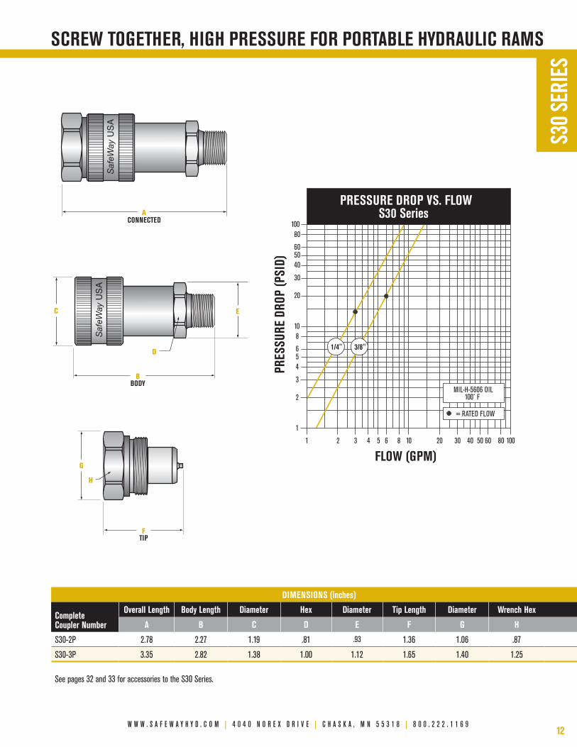
sCrew tOgether, high pressure FOr pOrtaBLe hYdrauLiC rams
CONNECTED BODY TIP F BA
D
G C E
H
Saf
eWay
USA
Saf
eWay
USA
CONNECTED BODY TIP F BA
D
G C E
H
Saf
eWay
USA
Saf
eWay
USA
CONNECTED BODY TIP F BA
D
G C E
H
Saf
eWay
USA
Saf
eWay
USA
S30
SERI
ES
PRESSURE DROP VS. FLOW S30 Series
FLOW (GPM)
PRES
SURE
DRO
P (P
SID)
1 2 3 4 5 6 8 10 20 30 40 50 60 80 100
1
2
3
4 5 6
8 10
20
30
40 50 60
80 100
MIL-H-5606 OIL 100˚ F
= RATED FLOW
1/4" 3/8"
dimensiOns (inches)
Complete Coupler number
Overall Length Body Length diameter hex diameter tip Length diameter wrench hex
a B C d e F g h
S30-2P 2.78 2.27 1.19 .81 .93 1.36 1.06 .87
S30-3P 3.35 2.82 1.38 1.00 1.12 1.65 1.40 1.25
See pages 32 and 33 for accessories to the S30 Series.
13
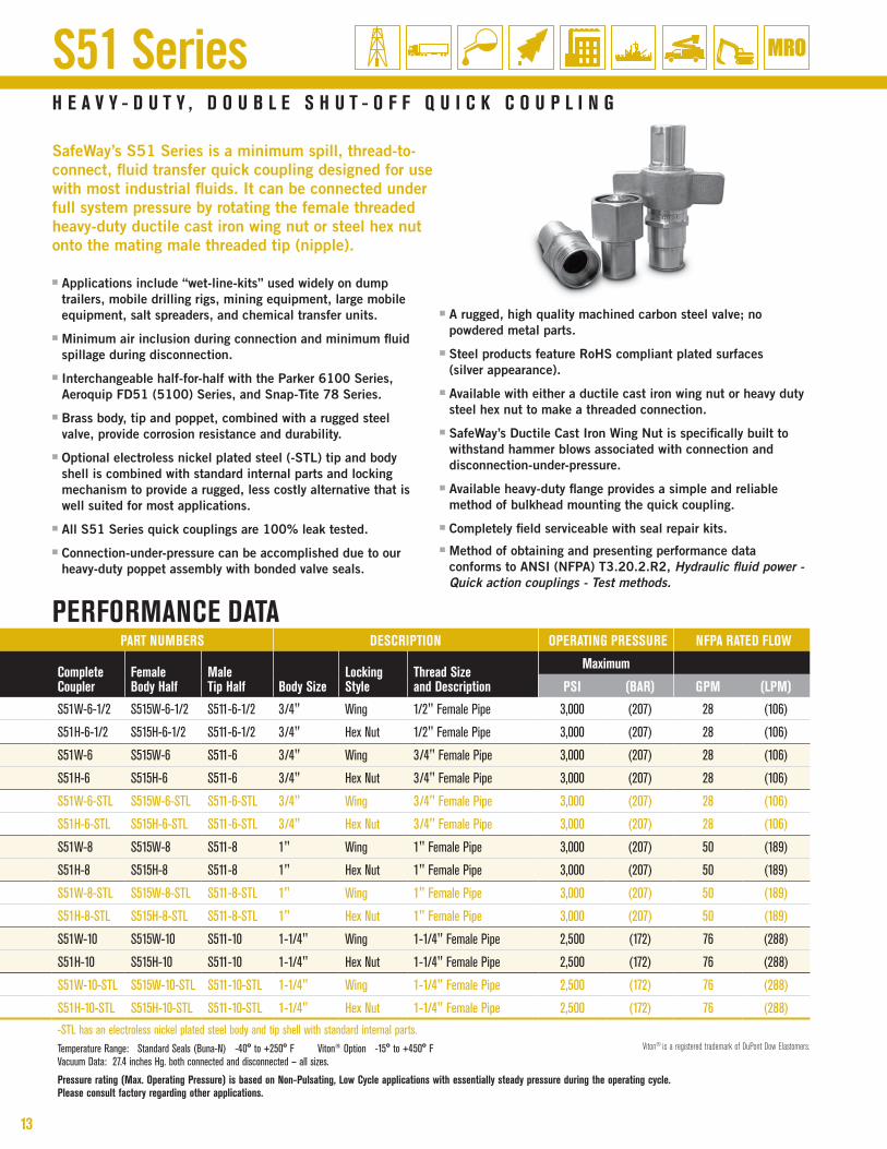
■ Applications include “wet-line-kits” used widely on dump trailers, mobile drilling rigs, mining equipment, large mobile equipment, salt spreaders, and chemical transfer units.
■ minimum air inclusion during connection and minimum fluid spillage during disconnection.
■ Interchangeable half-for-half with the parker 6100 Series, Aeroquip FD51 (5100) Series, and Snap-Tite 78 Series.
■ brass body, tip and poppet, combined with a rugged steel valve, provide corrosion resistance and durability.
■ optional electroless nickel plated steel (-STl) tip and body shell is combined with standard internal parts and locking mechanism to provide a rugged, less costly alternative that is well suited for most applications.
■ All S51 Series quick couplings are 100% leak tested.
■ connection-under-pressure can be accomplished due to our heavy-duty poppet assembly with bonded valve seals.
■ A rugged, high quality machined carbon steel valve; no powdered metal parts.
■ Steel products feature rohS compliant plated surfaces (silver appearance).
■ Available with either a ductile cast iron wing nut or heavy duty steel hex nut to make a threaded connection.
■ SafeWay’s Ductile cast Iron Wing nut is specifically built to withstand hammer blows associated with connection and disconnection-under-pressure.
■ Available heavy-duty flange provides a simple and reliable method of bulkhead mounting the quick coupling.
■ completely field serviceable with seal repair kits.■ method of obtaining and presenting performance data
conforms to AnSI (nFpA) T3.20.2.r2, Hydraulic fluid power - Quick action couplings - Test methods.
h e a v Y - d u t Y , d O u B L e s h u t - O F F Q u i C k C O u p L i n g
SafeWay’s S51 Series is a minimum spill, thread-to-connect, fluid transfer quick coupling designed for use with most industrial fluids. It can be connected under full system pressure by rotating the female threaded heavy-duty ductile cast iron wing nut or steel hex nut onto the mating male threaded tip (nipple).
S51 Series
part numBers desCriptiOn Operating pressure nFpa rated FLOw
Complete Coupler
Female Body half
maletip half Body size
Locking style
thread size and description
maximum
psi (Bar) gpm (Lpm)
S51W-6-1/2 S515W-6-1/2 S511-6-1/2 3/4" Wing 1/2" Female Pipe 3,000 (207) 28 (106)
S51H-6-1/2 S515H-6-1/2 S511-6-1/2 3/4" Hex Nut 1/2" Female Pipe 3,000 (207) 28 (106)
S51W-6 S515W-6 S511-6 3/4" Wing 3/4" Female Pipe 3,000 (207) 28 (106)
S51H-6 S515H-6 S511-6 3/4" Hex Nut 3/4" Female Pipe 3,000 (207) 28 (106)
S51W-6-STL S515W-6-STL S511-6-STL 3/4" Wing 3/4" Female Pipe 3,000 (207) 28 (106)
S51H-6-STL S515H-6-STL S511-6-STL 3/4" Hex Nut 3/4" Female Pipe 3,000 (207) 28 (106)
S51W-8 S515W-8 S511-8 1" Wing 1" Female Pipe 3,000 (207) 50 (189)
S51H-8 S515H-8 S511-8 1" Hex Nut 1" Female Pipe 3,000 (207) 50 (189)
S51W-8-STL S515W-8-STL S511-8-STL 1" Wing 1" Female Pipe 3,000 (207) 50 (189)
S51H-8-STL S515H-8-STL S511-8-STL 1" Hex Nut 1" Female Pipe 3,000 (207) 50 (189)
S51W-10 S515W-10 S511-10 1-1/4" Wing 1-1/4" Female Pipe 2,500 (172) 76 (288)
S51H-10 S515H-10 S511-10 1-1/4" Hex Nut 1-1/4" Female Pipe 2,500 (172) 76 (288)
S51W-10-STL S515W-10-STL S511-10-STL 1-1/4" Wing 1-1/4" Female Pipe 2,500 (172) 76 (288)
S51H-10-STL S515H-10-STL S511-10-STL 1-1/4" Hex Nut 1-1/4" Female Pipe 2,500 (172) 76 (288)
-STL has an electroless nickel plated steel body and tip shell with standard internal parts.Temperature Range: Standard Seals (Buna-N) -40° to +250° F Viton® Option -15° to +450° F Vacuum Data: 27.4 inches Hg. both connected and disconnected — all sizes.
pressure rating (max. Operating pressure) is based on non-pulsating, Low Cycle applications with essentially steady pressure during the operating cycle. please consult factory regarding other applications.
perFOrmanCe data
Viton® is a registered trademark of DuPont Dow Elastomers.

w w w . s a f e w a y h y d . c o m | 4 0 4 0 n o r e x d r i v e | c h a s k a , m n 5 5 3 1 8 | 8 0 0 . 2 2 2 . 1 1 6 914
E
G
C
FTIP
ACONNECTED
BBODY
BBODY
HEX NUT
WING NUT
CO
NN
ECTED
SafeW
ay US
A
D
H J
SafeW
ay US
A
Saf
eWay
US
A
Saf
eW
ay U
SA
K
Saf
eWay
US
A
CO
NN
ECTED
E
G
C
FTIP
ACONNECTED
BBODY
BBODY
HEX NUT
WING NUT
CO
NN
ECTED
SafeW
ay US
A
D
H J
SafeW
ay US
A
Saf
eWay
US
A
Saf
eW
ay U
SA
K
Saf
eWay
US
A
CO
NN
ECTED
E
G
C
FTIP
ACONNECTED
BBODY
BBODY
HEX NUT
WING NUT
CO
NN
ECTED
SafeW
ay US
A
D
H J
SafeW
ay US
A
Saf
eWay
US
A
Saf
eW
ay U
SA
K
Saf
eWay
US
A
CO
NN
ECTED
E
G
C
FTIP
ACONNECTED
BBODY
BBODY
HEX NUT
WING NUT
CO
NN
ECTED
SafeW
ay US
A
D
H J
SafeW
ay US
A
Saf
eWay
US
A
Saf
eW
ay U
SA
K
Saf
eWay
US
A
CO
NN
ECTED
PRESSURE DROP VS. FLOW S51 Series
FLOW (GPM)
PRES
SURE
DRO
P (P
SID)
1 2 3 4 5 6 8 10 20 30 40 50 60 80 100
1
2
3
4 5 6
8 10
20
30
40 50 60
80 100
MIL-H-5606 OIL 100˚ F
= RATED FLOW
3/4" 1" 1-1/4"
sCrew tOgether, maximum FLOw with minimaL spiLLage
S51
SERI
ES
dimensiOns (inches)
Complete Coupler number
Overall Length Body Length wing nut Length wrench Flat diameter tip Length diameter wrench Flat hex hex
a B C d e F g h J k
S51W-6-1/2 4.75 2.72 4.06 1.16 1.25 3.05 1.36 1.16 1.62 —
S51H-6-1/2 4.75 2.72 — 1.16 1.25 3.05 1.36 1.16 1.62 1.75
S51W-6 4.75 2.72 4.06 1.16 1.25 3.05 1.36 1.16 1.62 —
S51H-6 4.75 2.72 — 1.16 1.25 3.05 1.36 1.16 1.62 1.75
S51W-6-STL 4.75 2.72 4.06 1.16 1.25 3.05 1.36 1.16 1.62 —
S51H-6-STL 4.75 2.72 — 1.16 1.25 3.05 1.36 1.16 1.62 1.75
S51W-8 5.40 3.32 4.38 1.43 1.56 3.30 1.74 1.56 1.88 —
S51H-8 5.40 3.32 — 1.43 1.56 3.30 1.74 1.56 1.88 2.12
S51W-8-STL 5.40 3.32 4.38 1.43 1.56 3.30 1.74 1.56 1.88 —
S51H-8-STL 5.40 3.32 — 1.43 1.56 3.30 1.74 1.56 1.88 2.12
S51W-10 5.69 3.66 5.20 1.77 1.89 3.42 2.08 1.88 2.12 —
S51H-10 5.69 3.66 — 1.77 1.89 3.42 2.08 1.88 2.12 2.50
S51W-10-STL 5.69 3.66 5.20 1.77 1.89 3.42 2.08 1.88 2.12 —
S51H-10-STL 5.69 3.66 — 1.77 1.89 3.42 2.08 1.88 2.12 2.50
-STL has an electroless nickel plated steel body and tip shell with standard internal parts. See pages 32 and 33 for accessories to the S51 Series.

15
■ meets dimensional requirements of ISo 7241-1 Series A.
■ A general purpose, fluid transfer quick coupling that provides higher burst pressure and superior flow to that of Aeroquip FD56 (5600) series and parker 6600 series, while providing half-for-half interchangeability.
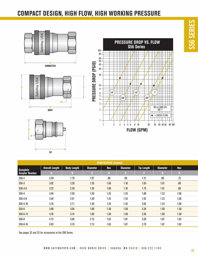
■ Due to SafeWay’s unique poppet style valving, the S56 Series has a shorter overall length and less weight than other brands they replace.
■ manufactured from solid steel barstock.
■ Available in body sizes from 1/4" to 1" with pipe thread and SAe o-ring boss (orb) standard.
■ All S56 Series quick couplings are 100% leak tested.
■ Ideal for minimal space applications.
■ Steel products feature rohS compliant plated surfaces (silver appearance).
■ heavy-duty dust plugs and dust caps available.
■ heavy-duty detent ball latch design for reliable connection time after time.
■ The S56 Series uses solid steel barstock in its valving and retainers; no powdered metal parts. A higher number of detent (locking) balls and a specially hardened male tip (nipple) add to the overall integrity of the product and its higher rated work-ing pressure.
■ unique poppet/seat design allows no extrusion gap, minimizing seal degradation under extreme pressures. Stainless steel valve springs and retainer rings are standard.
■ method of obtaining and presenting performance data conforms to AnSI (nFpA) T3.20.2.r2, Hydraulic fluid power - Quick action couplings - Test methods.
v e r s a t i L e h Y d r a u L i C & F L u i d t r a n s F e r C O u p L i n g s
SafeWay’s S56 Series is a general purpose, double shut-off quick coupling capable of containing a wide variety of fluids. This series can be found anywhere a dependable connection and disconnection of a fluid transfer line is required. rugged construction and low pressure drop make this series ideal for a variety of applications including plant maintenance equipment, skid steer loaders, snow plows, mining, dump trucks, gooseneck trailers and chemical transfer lines.
S56 Series
part numBers desCriptiOn Operating pressure nFpa rated FLOw
Complete Coupler
Female Body half
maletip half Body size
thread size and description
maximum
psi (Bar) gpm (Lpm)
S56-2 S565-2 S561-2 1/4" 1/4" Female Pipe 5,000 (345) 3 (12)
S56-3 S565-3 S561-3 3/8" 3/8" Female Pipe 4,500 (310) 6 (23)
S56-3-6 S565-3-6 S561-3-6 3/8" 9/16"-18 Female ORB 4,500 (310) 6 (23)
S56-4 S565-4 S561-4 1/2" 1/2" Female Pipe 4,000 (276) 12 (45)
S56-4-8 S565-4-8 S561-4-8 1/2" 3/4"-16 Female ORB 4,000 (276) 12 (45)
S56-4-10 S565-4-10 S561-4-10 1/2" 7/8"-14 Female ORB 4,000 (276) 12 (45)
S56-6 S565-6 S561-6 3/4" 3/4" Female Pipe 4,000 (276) 28 (106)
S56-6-12 S565-6-12 S561-6-12 3/4" 1-1/16"-12 Female ORB 4,000 (276) 28 (106)
S56-8 S565-8 S561-8 1" 1" Female Pipe 4,000 (276) 50 (189)
S56-8-16 S565-8-16 S561-8-16 1" 1-5/16"-12 Female ORB 4,000 (276) 50 (189)
Temperature Range: Standard Seals (Buna-N) -40° to +250° F Viton® Option -15° to +450° F Other Seals Available. Vacuum Data: 27.4 inches Hg. both connected and disconnected.
pressure rating (max. Operating pressure) is based on non-pulsating, Low Cycle applications with essentially steady pressure during the operating cycle. please consult factory regarding other applications.
perFOrmanCe data
Viton® is a registered trademark of DuPont Dow Elastomers.
w w w . s a f e w a y h y d . c o m | 4 0 4 0 n o r e x d r i v e | c h a s k a , m n 5 5 3 1 8 | 8 0 0 . 2 2 2 . 1 1 6 916
PRESSURE DROP VS. FLOW S56 Series
FLOW (GPM)
PRES
SURE
DRO
P (P
SID)
1 2 3 4 5 6 8 10 20 30 40 50 60 80 100
1
2
3
4 5 6
8 10
20
30
40 50 60
80 100
MIL-H-5606 OIL 100˚ F
= RATED FLOW
3/4"
1/2"
3/8"
1/4" 1"
COmpaCt design, high FLOw, high wOrking pressure
EG C
FTIP
ACONNECTED
BBODY
H
D
Saf
eWay
USA
Saf
eWay
USA
EG C
FTIP
ACONNECTED
BBODY
H
D
Saf
eWay
USA
Saf
eWay
USA
EG C
FTIP
ACONNECTED
BBODY
H
D
Saf
eWay
USA
Saf
eWay
USA
S56
SERI
ES
dimensiOns (inches)
Complete Coupler number
Overall Length Body Length diameter hex diameter tip Length diameter hex
a B C d e F g h
S56-2 2.48 1.79 1.07 .88 .96 1.31 .86 .75
S56-3 3.02 2.20 1.26 1.06 1.18 1.65 1.01 .88
S56-3-6 3.22 2.30 1.26 1.06 1.18 1.75 1.01 .88
S56-4 3.46 2.56 1.50 1.25 1.35 1.88 1.23 1.06
S56-4-8 3.56 2.61 1.50 1.25 1.35 1.93 1.23 1.06
S56-4-10 3.76 2.71 1.50 1.25 1.35 2.03 1.23 1.06
S56-6 3.98 3.04 1.89 1.38 1.58 2.26 1.58 1.38
S56-6-12 4.18 3.14 1.89 1.38 1.58 2.36 1.58 1.38
S56-8 4.73 3.66 2.13 1.63 1.87 2.69 1.87 1.63
S56-8-16 4.93 3.76 2.13 1.63 1.87 2.79 1.87 1.63
See pages 32 and 33 for accessories to the S56 Series.
17
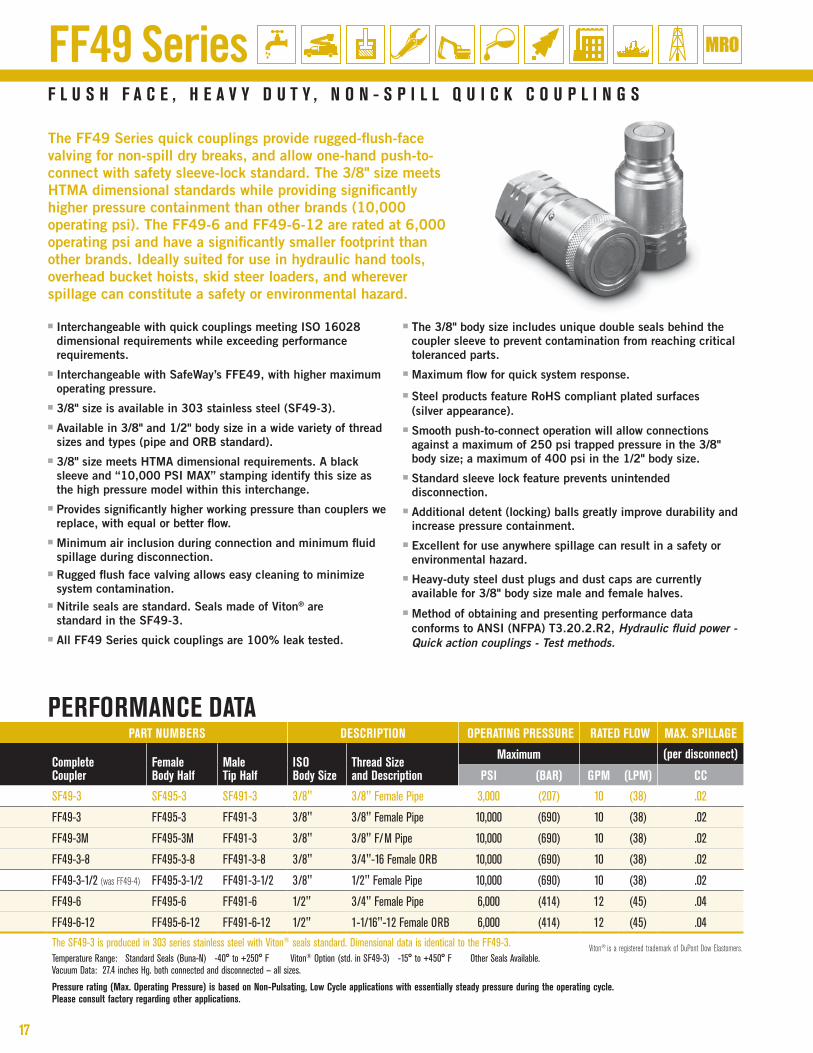
■ Interchangeable with quick couplings meeting ISo 16028 dimensional requirements while exceeding performance requirements.
■ Interchangeable with SafeWay’s FFe49, with higher maximum operating pressure.
■ 3/8" size is available in 303 stainless steel (SF49-3).■ Available in 3/8" and 1/2" body size in a wide variety of thread
sizes and types (pipe and orb standard). ■ 3/8" size meets hTmA dimensional requirements. A black
sleeve and “10,000 pSI mAx” stamping identify this size as the high pressure model within this interchange.
■ provides significantly higher working pressure than couplers we replace, with equal or better flow.
■ minimum air inclusion during connection and minimum fluid spillage during disconnection.
■ rugged flush face valving allows easy cleaning to minimize system contamination.
■ nitrile seals are standard. Seals made of Viton® are standard in the SF49-3.
■ All FF49 Series quick couplings are 100% leak tested.
■ The 3/8" body size includes unique double seals behind the coupler sleeve to prevent contamination from reaching critical toleranced parts.
■ maximum flow for quick system response.
■ Steel products feature rohS compliant plated surfaces (silver appearance).
■ Smooth push-to-connect operation will allow connections against a maximum of 250 psi trapped pressure in the 3/8" body size; a maximum of 400 psi in the 1/2" body size.
■ Standard sleeve lock feature prevents unintended disconnection.
■ Additional detent (locking) balls greatly improve durability and increase pressure containment.
■ excellent for use anywhere spillage can result in a safety or environmental hazard.
■ heavy-duty steel dust plugs and dust caps are currently available for 3/8" body size male and female halves.
■ method of obtaining and presenting performance data conforms to AnSI (nFpA) T3.20.2.r2, Hydraulic fluid power - Quick action couplings - Test methods.
F L u s h F a C e , h e a v Y d u t Y , n O n - s p i L L Q u i C k C O u p L i n g s
FF49 Series
The FF49 Series quick couplings provide rugged-flush-face valving for non-spill dry breaks, and allow one-hand push-to-connect with safety sleeve-lock standard. The 3/8" size meets hTmA dimensional standards while providing significantly higher pressure containment than other brands (10,000 operating psi). The FF49-6 and FF49-6-12 are rated at 6,000 operating psi and have a significantly smaller footprint than other brands. Ideally suited for use in hydraulic hand tools, overhead bucket hoists, skid steer loaders, and wherever spillage can constitute a safety or environmental hazard.
perFOrmanCe data
Viton® is a registered trademark of DuPont Dow Elastomers.
part numBers desCriptiOn Operating pressure rated FLOw max. spiLLage
Complete Coupler
Female Body half
maletip half
isO Body size
thread size and description
maximum (per disconnect)
psi (Bar) gpm (Lpm) CC
SF49-3 SF495-3 SF491-3 3/8" 3/8" Female Pipe 3,000 (207) 10 (38) .02
FF49-3 FF495-3 FF491-3 3/8" 3/8" Female Pipe 10,000 (690) 10 (38) .02
FF49-3M FF495-3M FF491-3 3/8" 3/8" F/M Pipe 10,000 (690) 10 (38) .02
FF49-3-8 FF495-3-8 FF491-3-8 3/8" 3/4"-16 Female ORB 10,000 (690) 10 (38) .02
FF49-3-1/2 (was FF49-4) FF495-3-1/2 FF491-3-1/2 3/8" 1/2" Female Pipe 10,000 (690) 10 (38) .02
FF49-6 FF495-6 FF491-6 1/2" 3/4" Female Pipe 6,000 (414) 12 (45) .04
FF49-6-12 FF495-6-12 FF491-6-12 1/2" 1-1/16"-12 Female ORB 6,000 (414) 12 (45) .04
The SF49-3 is produced in 303 series stainless steel with Viton® seals standard. Dimensional data is identical to the FF49-3.Temperature Range: Standard Seals (Buna-N) -40° to +250° F Viton® Option (std. in SF49-3) -15° to +450° F Other Seals Available. Vacuum Data: 27.4 inches Hg. both connected and disconnected — all sizes.
pressure rating (max. Operating pressure) is based on non-pulsating, Low Cycle applications with essentially steady pressure during the operating cycle. please consult factory regarding other applications.

w w w . s a f e w a y h y d . c o m | 4 0 4 0 n o r e x d r i v e | c h a s k a , m n 5 5 3 1 8 | 8 0 0 . 2 2 2 . 1 1 6 918
PRESSURE DROP VS. FLOW FF49 Series
FLOW (GPM)
PRES
SURE
DRO
P (P
SID)
1 2 3 4 5 6 8 10 20 30 40 50 60 80 100
1
2
3
4 5 6
8 10
20
30
40 50 60
80 100
MIL-H-5606 OIL 100˚ F
= RATED FLOW
3/8" 1/2"
high pressure & high FLOw withOut spiLLage
EIG C
FTIP
H
ACONNECTED
BBODY
D
Saf
eWay
MAD
E IN
USA
SafeW
ayM
ADE IN
USA
SafeW
ayM
ADE IN
USA S
afeW
ay
MAD
E IN
USA
EIG C
FTIP
H
ACONNECTED
BBODY
D
Saf
eWay
MAD
E IN
USA
SafeW
ayM
ADE IN
USA
SafeW
ayM
ADE IN
USA S
afeW
ay
MAD
E IN
USA
EIG C
FTIP
H
ACONNECTED
BBODY
D
Saf
eWay
MAD
E IN
USA
SafeW
ayM
ADE IN
USA
SafeW
ayM
ADE IN
USA S
afeW
ay
MAD
E IN
USA
FF49
SER
IES
dimensiOns (inches)
Complete Coupler number
Overall Length Body Length diameter hex diameter tip Length diameter hex tip diameter
a B C d e F g h i
SF49-3 4.19 2.47 1.19 1.12 1.24 2.35 1.04 .94 .78
FF49-3 4.19 2.47 1.19 1.12 1.24 2.35 1.04 .94 .78
FF49-3M 4.47 2.75 1.19 1.12 1.24 2.35 1.04 .94 .78
FF49-3-8 4.56 2.67 1.19 1.12 1.24 2.52 1.18 1.06 .78
FF49-3-1/2 4.54 2.67 1.19 1.12 1.24 2.50 1.18 1.06 .78
FF49-6 5.20 3.06 1.50 1.38 1.57 2.81 1.55 1.38 .96
FF49-6-12 5.60 3.29 1.50 1.38 1.57 2.98 1.55 1.38 .96
See pages 32 and 33 for accessories to the FF49 Series.

19
FFE49 Series
part numBers desCriptiOn Operating pressure nFpa rated FLOw max. spiLLage
Complete Coupler
Female Body half
maletip half
isO Body size
thread size and description
maximum (per disconnect)
psi (Bar) gpm (Lpm) CC
FFE49-2 FFE495-2 FFE491-2 1/4" 1/4" Female NPT 5,000 (345) 3 (12) .01
FFE49-4 FFE495-4 FFE491-4 1/2" 1/2" Female NPT 4,000 (276) 12 (45) .04
FFE49-4-3/4 FFE495-4-3/4 FFE491-4-3/4 1/2" 3/4" Female NPT 4,000 (276) 12 (45) .04
FFE49-4-10 FFE495-4-10 FFE491-4-10 1/2" 7/8"-14 Female ORB 4,000 (276) 12 (45) .04
FFE49-4-12 FFE495-4-12 FFE491-4-12 1/2" 1-1/16"-12 Female ORB 4,000 (276) 12 (45) .04
FFE49-6 FFE495-6 FFE491-6 3/4" 3/4" Female NPT 4,000 (276) 26 (100) .10
FFE49-6-1 FFE495-6-1 FFE491-6-1 3/4" 1" Female NPT 4,000 (276) 26 (100) .10
FFE49-6-16 FFE495-6-16 FFE491-6-16 3/4" 1-5/16"-12 Female ORB 4,000 (276) 26 (100) .10
FFE49-8 FFE495-8 FFE491-8 1" 1" Female NPT 3,000 (207) 50 (189) .20
FFE49-8-114 FFE495-8-114 FFE491-8-114 1" 1-1/4" Female NPT 3,000 (207) 50 (189) .20
FFE49-8-20 FFE495-8-20 FFE491-8-20 1" 1-5/8"-12 Female ORB 3,000 (207) 50 (189) .20
Temperature Range: Standard Seals (Buna-N) -40° to +250° F Viton® Option -15° to +450° F Other Seals Available. Vacuum Data: 27.4 inches Hg. both connected and disconnected — all sizes.
pressure rating (max. Operating pressure) is based on non-pulsating, Low Cycle applications with essentially steady pressure during the operating cycle. please consult factory regarding other applications.
perFOrmanCe data
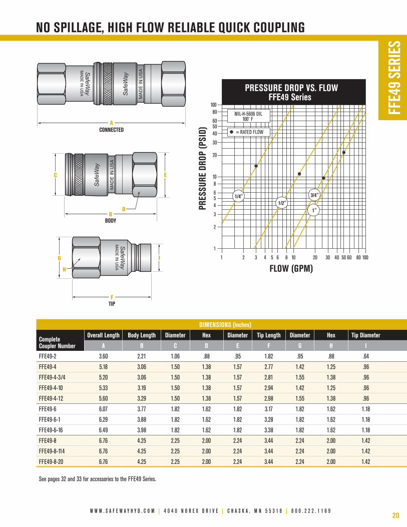
■ Smooth, one hand, push-to-connect locking mechanism.■ minimum air inclusion during connection and minimum fluid
spillage during disconnection.■ Interchangeable half-for-half with parker Fem Series,
Aeroquip FD89, holmbury hQ Series, Faster 2FFI Series, and others conforming to ISo 16028 dimensional requirements.
■ rugged flush face valving allows easy cleaning to minimize system contamination.
■ maximum flow for quick system response.■ Available in ISo 1/4" through ISo 1" body size in a variety of
thread sizes and styles.■ If you require a 3/8" size please use the FF49 Series, which
meets the interchange requirements of ISo 16028 while providing higher operating psi.
■ Anti-blowout buna and Teflon® tip half seals reduce the likelihood of premature failure due to connection under residual system pressure. This residual system pressure is 250 psi max. in the 3/8" body size and higher in the other sizes.
■ Steel products feature rohS compliant plated surfaces (silver appearance).
■ All FFe49 Series quick couplings are 100% leak tested before leaving the factory.
■ heat treated surfaces resist wear.■ Sleeve lock option, to minimize accidental disconnect, is
available upon request.■ method of obtaining and presenting performance data
conforms to AnSI (nFpA) T3.20.2.r2, Hydraulic fluid power - Quick action couplings - Test methods.
SafeWay’s FFe49 Series is a non-spill, push-to-connect, fluid transfer quick coupling designed for use with most industrial fluids. This series is interchangeable with quick couplings meeting Industry Standard ISo 16028 dimensional requirements, and our field proven, heavy-duty FF49 Series. Some basic applications include skid steer loaders, power utility equipment, construction equipment, agricultural equipment, and hydraulic hand tools. use this quick coupling series whenever spillage can result in a safety or environmental hazard, when air inclusion during connection to a hydraulic system cannot be tolerated, and when international interchangeability with other brands is required.
Viton® is a registered trademark of DuPont Dow Elastomers.Teflon® is a registered trademark of DuPont Co.
F L u s h F a C e , n O n - s p i L L Q u i C k C O u p L i n g s
w w w . s a f e w a y h y d . c o m | 4 0 4 0 n o r e x d r i v e | c h a s k a , m n 5 5 3 1 8 | 8 0 0 . 2 2 2 . 1 1 6 920
PRESSURE DROP VS. FLOW FFE49 Series
FLOW (GPM)
PRES
SURE
DRO
P (P
SID)
1 2 3 4 5 6 8 10 20 30 40 50 60 80 100
1
2
3
4 5 6
8 10
20
30
40 50 60
80 100
MIL-H-5606 OIL 100˚ F
= RATED FLOW
3/4"1/2"
1/4"
1"
FFE4
9 SE
RIES
dimensiOns (inches)
Complete Coupler number
Overall Length Body Length diameter hex diameter tip Length diameter hex tip diameter
a B C d e F g h i
FFE49-2 3.60 2.21 1.06 .88 .95 1.82 .95 .88 .64
FFE49-4 5.18 3.06 1.50 1.38 1.57 2.77 1.42 1.25 .96
FFE49-4-3/4 5.20 3.06 1.50 1.38 1.57 2.81 1.55 1.38 .96
FFE49-4-10 5.33 3.19 1.50 1.38 1.57 2.94 1.42 1.25 .96
FFE49-4-12 5.60 3.29 1.50 1.38 1.57 2.98 1.55 1.38 .96
FFE49-6 6.07 3.77 1.82 1.62 1.82 3.17 1.82 1.62 1.18
FFE49-6-1 6.29 3.88 1.82 1.62 1.82 3.28 1.82 1.62 1.18
FFE49-6-16 6.49 3.98 1.82 1.62 1.82 3.38 1.82 1.62 1.18
FFE49-8 6.76 4.25 2.25 2.00 2.24 3.44 2.24 2.00 1.42
FFE49-8-114 6.76 4.25 2.25 2.00 2.24 3.44 2.24 2.00 1.42
FFE49-8-20 6.76 4.25 2.25 2.00 2.24 3.44 2.24 2.00 1.42
See pages 32 and 33 for accessories to the FFE49 Series.
nO spiLLage, high FLOw reLiaBLe QuiCk COupLing
MAD
E IN U
SA S
afeWay
EIG C
FTIP
H
ACONNECTED
BBODY
DS
afeW
ay
MAD
E IN
USA
Saf
eWay
MAD
E IN
USA
MAD
E IN U
SA S
afeWay
MAD
E IN U
SA S
afeWay
EIG C
FTIP
H
ACONNECTED
BBODY
D
Saf
eWay
MAD
E IN
USA
Saf
eWay
MAD
E IN
USA
MAD
E IN U
SA S
afeWay
MAD
E IN U
SA S
afeWay
EIG C
FTIP
H
ACONNECTED
BBODY
D
Saf
eWay
MAD
E IN
USA
Saf
eWay
MAD
E IN
USA
MAD
E IN U
SA S
afeWay

21
FFEC49 SeriesF L u s h F a C e , n O n - s p i L L , C O n n e C t - u n d e r - p r e s s u r e
SafeWay’s FFec49 Series allows one-hand connection with trapped residual pressure in the nipple. It works with Industry Standard ISo 16028 female couplers in 1/2" body sizes from SafeWay and other manufacturers. SafeWay's FFec49 Series products are widely used in the mobile equipment and construction markets on hydraulic attachments for skid steer loaders and hydraulic tools. Ideal for use in environments where thermal expansion of trapped fluid from temperature change or exposure to sun makes connection of the mating half difficult.
■ minimum air inclusion during connection and minimum fluid spillage during disconnection.
■ Interchangeable with parker Fec-502-8Fp.■ bi-directional flow.■ nipple connects under residual pressure by hand.■ hardened locking surface.■ All FFec49 Series couplings are 100% leak tested.■ rohS compliant plated surfaces (silver appearance).■ Dimensionally interchangable with all ISo 16028
compliant 1/2" male tips.■ heavy duty steel construction.■ method of obtaining and presenting performance data
conforms to AnSI (nFpA) T3.20.2.r2, Hydraulic fluid power - Quick action couplings - Test methods.
Safe
Way
USA
A
B C
D E
TIP
part numBers desCriptiOn COnneCt-under-pressure Operating pressure nFpa rated FLOw max. spiLLage
male tipisO Body size
thread size and description
maximum maximum (per disconnect)
psi (Bar) psi (Bar) gpm (Lpm) CC
FFEC491-4 1/2" 1/2" Female Pipe 3,000 (207) 4,000 (276) 12 (45) .04
dimensiOns (inches)
Connect-under-pressure male tip
Overall Length diameter diameter hex hex
a B C d e
FFEC491-4 3.56 1.35 1.20 1.25 1.12Temperature Range: Standard Seals (Buna-N) -40° to +250° F Viton® Option -15° to +450° F Other Seals Available. Vacuum Data: 27.4 inches Hg. both connected and disconnected — all sizes.
pressure rating (max. Operating pressure) is based on non-pulsating, Low Cycle applications with essentially steady pressure during the operating cycle. please consult factory regarding other applications.
perFOrmanCe data
Viton® is a registered trademark of DuPont Dow Elastomers.
3 4
PRES
SURE
DRO
P (P
SID)
21
30
1
2
34568
10
20
40506080
100
FLOW (GPM)
3020 60 80 1005 6 8 10 5040
MIL-H-5606 OIL100˚ F
= RATED FLOW
PRESSURE DROP VS FLOWFFEC49 Series
FFEC
49 S
ERIE
S
w w w . s a f e w a y h y d . c o m | 4 0 4 0 n o r e x d r i v e | c h a s k a , m n 5 5 3 1 8 | 8 0 0 . 2 2 2 . 1 1 6 922
FDB49 SeriesF L u s h Fa C e , n O n - s p i L L , 3 1 6 L s ta i n L e s s s t e e L , h a n s O n d B i n t e r C h a n g e
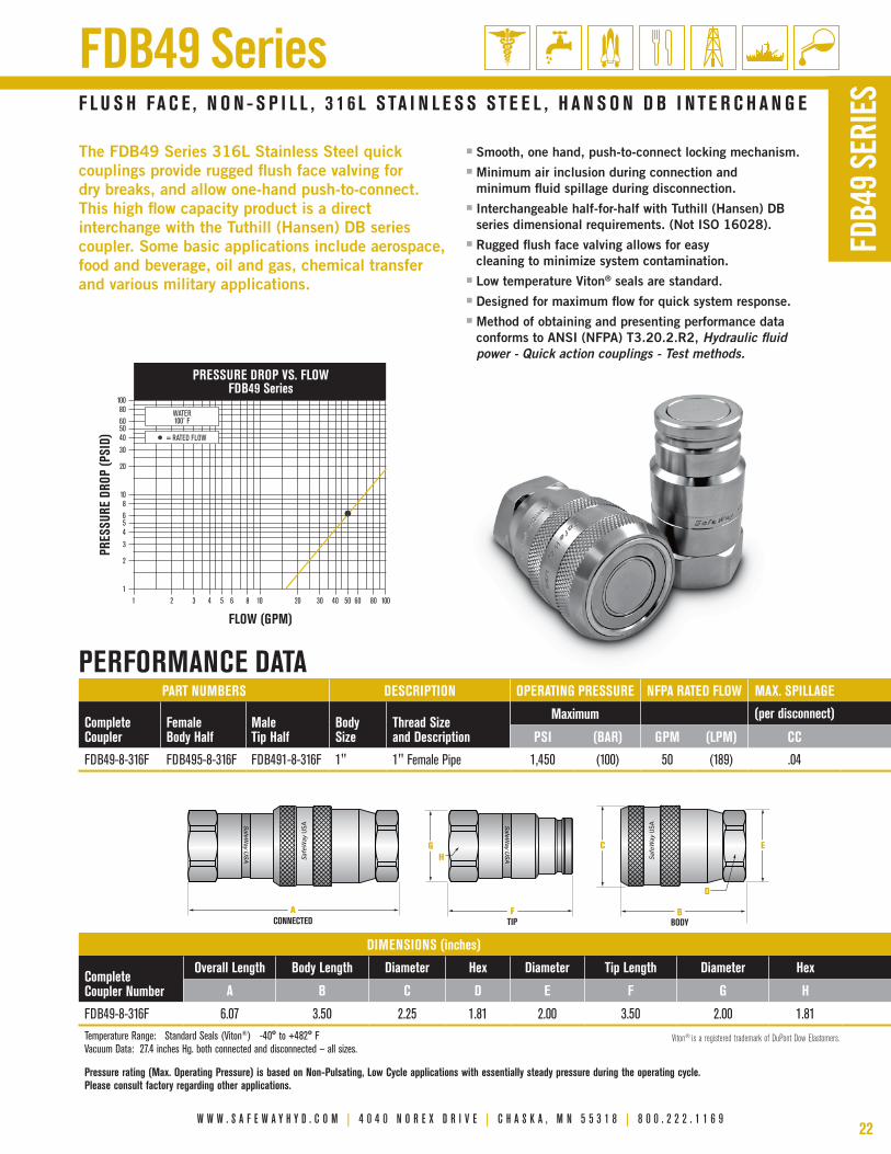
The FDb49 Series 316l Stainless Steel quick couplings provide rugged flush face valving for dry breaks, and allow one-hand push-to-connect. This high flow capacity product is a direct interchange with the Tuthill (hansen) Db series coupler. Some basic applications include aerospace, food and beverage, oil and gas, chemical transfer and various military applications.
■ Smooth, one hand, push-to-connect locking mechanism.■ minimum air inclusion during connection and
minimum fluid spillage during disconnection.■ Interchangeable half-for-half with Tuthill (hansen) Db
series dimensional requirements. (not ISo 16028).■ rugged flush face valving allows for easy
cleaning to minimize system contamination.■ low temperature Viton® seals are standard.■ Designed for maximum flow for quick system response.■ method of obtaining and presenting performance data
conforms to AnSI (nFpA) T3.20.2.r2, Hydraulic fluid power - Quick action couplings - Test methods.
FDB4
9 SE
RIES
part numBers desCriptiOn Operating pressure nFpa rated FLOw max. spiLLage
Complete Coupler
Female Body half
maletip half
Body size
thread size and description
maximum (per disconnect)
psi (Bar) gpm (Lpm) CC
FDB49-8-316F FDB495-8-316F FDB491-8-316F 1" 1" Female Pipe 1,450 (100) 50 (189) .04
perFOrmanCe data
dimensiOns (inches)
Complete Coupler number
Overall Length Body Length diameter hex diameter tip Length diameter hex
a B C d e F g h
FDB49-8-316F 6.07 3.50 2.25 1.81 2.00 3.50 2.00 1.81Temperature Range: Standard Seals (Viton®) -40° to +482° F Vacuum Data: 27.4 inches Hg. both connected and disconnected — all sizes.
pressure rating (max. Operating pressure) is based on non-pulsating, Low Cycle applications with essentially steady pressure during the operating cycle. please consult factory regarding other applications.
Viton® is a registered trademark of DuPont Dow Elastomers.
SafeWay U
SA Safe
Way
USA SafeW
ay USA Sa
feW
ay U
SA
ACONNECTED
GH
FTIP
C E
D
BBODY
1 6432 100806020 30 40 501085
100
605040
30
20
108
654
3
2
1
80
PRESSURE DROP VS. FLOWFDB49 Series
FLOW (GPM)
PRES
SURE
DRO
P (P
SID)
WATER100˚ F
= RATED FLOW

23
■ 1/2" body size meets dimensional requirements of ISo 5675.
■ Available in body sizes from 1/4" through 1", in a variety of thread sizes and styles.
■ Double shut-off design available with either a rugged ball valve or leak-free, high flow poppet valve.
■ All poppet valve models are 100% leak tested before leaving the factory.
■ reliable and durable ball locking mechanism provides smooth operation time after time.
■ critical parts are hardened for long service life.
■ Steel products feature rohS compliant plated surfaces (silver appearance).
■ one-way sleeve design allows implement break-away when the coupling is clamp mounted.
■ Interchangeable half-for-half with the parker/pioneer 4000 Series.
■ referred to as “old reliable” by hands-on users.
■ Dust plugs and dust caps available.
■ heavy-duty double break-away clamp available.■ method of obtaining and presenting performance data
conforms to AnSI (nFpA) T3.20.2.r2, Hydraulic fluid power - Quick action couplings - Test methods.
r e L i a B L e , e C O n O m i C a L , g e n e r a L p u r p O s e C O u p L i n g s
SafeWay’s S20 Series is a general purpose, double shut-off, fluid transfer quick coupling available with either a rugged ball valve or leak-free, high flow poppet valve. The S20 Series is used primarily on agricultural equipment and is recognized as an economical and reliable quick coupling. This series is original equipment on snow plows, garden tractors, full size tractors, front-end loaders, skid steer loaders, earth moving, and mining equipment.
S20 Series
part numBers desCriptiOn Operating pressure nFpa rated FLOw
Complete Coupler
Female Body half
maletip half Body size
thread size and description
maximum
psi (Bar) gpm (Lpm)
S20A-2 S25A-2 S41-2 1/4" 1/4" Female Pipe 3,000 (207) 3 (12)
S20A-2P S25A-2P S41-2P 1/4" 1/4" Female Pipe 3,000 (207) 3 (12)
S20-3 S25-3 S41-3 3/8" 3/8" Female Pipe 3,000 (207) 6 (23)
S20-3P S25-3P S41-3P 3/8" 3/8" Female Pipe 3,000 (207) 6 (23)
S20-4 S25-4 S71-4 1/2" 1/2" Female Pipe 3,000 (207) 12 (45)
S20-4P S25-4P S71-4P 1/2" 1/2" Female Pipe 3,000 (207) 12 (45)
S20-4P-BSP S25-4P-BSP S561-4-BSP 1/2" G 1/2" BSPP Female 4,000 (276) 12 (45)
S20-15 S25-15 S71-15 1/2" 3/4"-16 Female ORB 3,000 (207) 12 (45)
S20-15P S25-15P S71-15P 1/2" 3/4"-16 Female ORB 3,000 (207) 12 (45)
S20-16 S25-16 S71-16 1/2" 7/8"-14 Female ORB 3,000 (207) 12 (45)
S20-16P S25-16P S71-16P 1/2" 7/8"-14 Female ORB 3,000 (207) 12 (45)
S20F-6 S25F-6 S21F-6 3/4" 3/4" Female Pipe 3,000 (207) 28 (106)
S20-8P S25-8P S21-8P 1" 1" Female Pipe 3,000 (207) 50 (189)
Temperature Range: Standard Seals (Buna-N) -40° to +250° F Viton® Option -15° to +450° F Other Seals Available. Vacuum Data: 27.4 inches Hg. both connected and disconnected — Poppet valved models in all sizes (P suffix).
pressure rating (max. Operating pressure) is based on non-pulsating, Low Cycle applications with essentially steady pressure during the operating cycle. please consult factory regarding other applications.
perFOrmanCe data
Viton® is a registered trademark of DuPont Dow Elastomers.

w w w . s a f e w a y h y d . c o m | 4 0 4 0 n o r e x d r i v e | c h a s k a , m n 5 5 3 1 8 | 8 0 0 . 2 2 2 . 1 1 6 924
PRESSURE DROP VS. FLOW S20 Series
FLOW (GPM)
PRES
SURE
DRO
P (P
SID)
1 2 3 4 5 6 8 10 20 30 40 50 60 80 100
1
2
3
4 5 6
8 10
20
30
40 50 60
80 100
MIL-H-5606 OIL 100˚ F
= RATED FLOW
3/4"
1/2"
3/8"
1/4" 1"
generaL purpOse agriCuLturaL O.e.m. COupLings
EG C
FTIP
ACONNECTED
BBODY
Saf
eWay
USA
H
D
Saf
eWay
USA
EG C
FTIP
ACONNECTED
BBODY
Saf
eWay
USA
H
D
Saf
eWay
USA
EG C
FTIP
ACONNECTED
BBODY
Saf
eWay
USA
H
D
Saf
eWay
USA
S20
SERI
ES
dimensiOns (inches)
Complete Coupler number
Overall Length Body Length diameter wrench Flat diameter tip Length diameter hex
a B C d e F g h
S20A-2 2.52 1.94 1.06 .87 .88 1.32 .86 .75
S20A-2P 2.52 1.94 1.06 .87 .88 1.37 .86 .75
S20-3 3.03 2.31 1.32 .87 1.00 1.58 1.08 .94
S20-3P 3.03 2.31 1.32 .87 1.00 1.67 1.08 .94
S20-4 3.66 2.68 1.50 1.00 1.17 1.94 1.22 1.06
S20-4P 3.66 2.68 1.50 1.00 1.17 1.96 1.22 1.06
S20-4P-BSP 3.66 2.68 1.50 1.00 1.17 1.88 1.23 1.06
S20-15 3.66 2.68 1.50 1.00 1.17 1.94 1.22 1.06
S20-15P 3.66 2.68 1.50 1.00 1.17 1.96 1.22 1.06
S20-16 3.66 2.68 1.50 1.00 1.17 1.94 1.22 1.06
S20-16P 3.66 2.68 1.50 1.00 1.17 1.96 1.22 1.06
S20F-6 4.02 3.02 1.88 1.31 1.49 2.15 1.52 1.38
S20-8P 4.52 3.43 2.07 1.62 1.86 2.49 1.88 1.62
See pages 32 and 33 for accessories to the S20 Series.

25
■ 1/2" body size meets dimensional requirements of ISo 5675.
■ Two-way (double acting) sleeve of the S40 Series allows one-hand connect or disconnect when the coupling is clamp or bulkhead mounted.
■ Available in body sizes from 1/4" to 1/2", in a variety of thread sizes and styles.
■ Double shut-off design available with either a rugged ball valve or leak-free, high flow poppet valve.
■ reliable and durable ball locking mechanism provides smooth operation time after time.
■ critical parts are hardened for long service life.
■ Two-way sleeve design allows implement break-away when the coupling is clamp or bulkhead mounted.
■ Interchangeable half-for-half with parker/pioneer 4200 Series.
■ All poppet valve models are 100% leak tested before leaving the factory.
■ Steel products feature rohS compliant plated surfaces (silver appearance).
■ Dust plugs and dust caps available.
■ heavy-duty double break-away clamp available.
■ heavy-duty snap-rings for bulkhead mounting available. ■ method of obtaining and presenting performance data
conforms to AnSI (nFpA) T3.20.2.r2, Hydraulic fluid power - Quick action couplings - Test methods.
O n e - h a n d O p e r a t i O n , g e n e r a L p u r p O s e C O u p L i n g s
SafeWay’s S40 Series is a general purpose, double shut-off fluid transfer quick coupling available with either a rugged ball valve or leak-free, high flow poppet valve. The S40-4 was the first two-way (double acting) sleeve quick coupling, introduced by SafeWay in 1969 as our first product. The S40 Series is widely used wherever the ease and convenience of one-hand connection or disconnection is desired. It is original equipment on a wide variety of agricultural and mobile equipment.
S40 Series
part numBers desCriptiOn Operating pressure nFpa rated FLOw
Complete Coupler
Female Body half
maletip half Body size
thread size and description
maximum
psi (Bar) gpm (Lpm)
S40-2 S45-2 S41-2 1/4" 1/4" Female Pipe 3,000 (207) 3 (12)
S40-2P S45-2P S41-2P 1/4" 1/4" Female Pipe 3,000 (207) 3 (12)
S40-3 S45-3 S41-3 3/8" 3/8" Female Pipe 3,000 (207) 6 (23)
S40-3P S45-3P S41-3P 3/8" 3/8" Female Pipe 3,000 (207) 6 (23)
S40-3P-BSP S45-3P-BSP S41-3P-BSP 3/8" G 3/8" BSPP Female 3,000 (207) 6 (23)
S40-36 S45-36 S41-36 3/8" M16-1.5 Female Metric 3,000 (207) 6 (23)
S40-4 S45-4 S71-4 1/2" 1/2" Female Pipe 3,000 (207) 12 (45)
S40-4P S45-4P S71-4P 1/2" 1/2" Female Pipe 3,000 (207) 12 (45)
S40-4P-BSP S45-4P-BSP S561-4-BSP 1/2" G 1/2" BSPP Female 4,000 (276) 12 (45)
S40-15 S45-15 S71-15 1/2" 3/4"-16 Female ORB 3,000 (207) 12 (45)
S40-15P S45-15P S71-15P 1/2" 3/4"-16 Female ORB 3,000 (207) 12 (45)
S40-6 S45-6 S71-6 1/2" 3/4" Female Pipe 3,000 (207) 12 (45)
S40-6P S45-6P S71-6P 1/2" 3/4" Female Pipe 3,000 (207) 12 (45)
Temperature Range: Standard Seals (Buna-N) -40° to +250° F Viton® Option -15° to +450° F Other Seals Available. Vacuum Data: 27.4 inches Hg. both connected and disconnected — Poppet valved models in all sizes (P suffix).
pressure rating (max. Operating pressure) is based on non-pulsating, Low Cycle applications with essentially steady pressure during the operating cycle. please consult factory regarding other applications.
perFOrmanCe data
Viton® is a registered trademark of DuPont Dow Elastomers.

w w w . s a f e w a y h y d . c o m | 4 0 4 0 n o r e x d r i v e | c h a s k a , m n 5 5 3 1 8 | 8 0 0 . 2 2 2 . 1 1 6 926
EG C
FTIP
ACONNECTED
BBODY
Saf
eWay
USA
H
D
Saf
eWay
USA
EG C
FTIP
ACONNECTED
BBODY
Saf
eWay
USA
H
D
Saf
eWay
USA
EG C
FTIP
ACONNECTED
BBODY
Saf
eWay
USA
H
D
Saf
eWay
USA
PRESSURE DROP VS. FLOW S40 Series
FLOW (GPM)
PRES
SURE
DRO
P (P
SID)
1 2 3 4 5 6 8 10 20 30 40 50 60 80 100
1
2
3
4 5 6
8 10
20
30
40 50 60
80 100
MIL-H-5606 OIL 100˚ F
= RATED FLOW
3/8"
1/4" 1/2"
One-hand OperatiOn agriCuLturaL O.e.m. COupLings
S40
SERI
ES
dimensiOns (inches)
Complete Coupler number
Overall Length Body Length diameter wrench Flat diameter tip Length diameter hex
a B C d e F g h
S40-2 2.52 1.94 1.07 .75 .84 1.32 .86 .75
S40-2P 2.52 1.94 1.07 .75 .84 1.37 .86 .75
S40-3 3.03 2.31 1.32 .87 1.06 1.58 1.08 .94
S40-3P 3.03 2.31 1.32 .87 1.06 1.67 1.08 .94
S40-3P-BSP 3.03 2.31 1.32 .87 1.06 1.67 1.08 .94
S40-36 3.03 2.31 1.32 .87 1.06 1.58 1.08 .94
S40-4 3.66 2.68 1.50 .93 1.06 1.94 1.22 1.06
S40-4P 3.66 2.68 1.50 .93 1.06 1.96 1.22 1.06
S40-4P-BSP 3.66 2.68 1.50 .93 1.06 1.88 1.23 1.06
S40-15 3.66 2.68 1.50 .93 1.06 1.94 1.22 1.06
S40-15P 3.66 2.68 1.50 .93 1.06 1.96 1.22 1.06
S40-6 4.07 2.90 1.50 1.25 1.43 2.16 1.43 1.25
S40-6P 4.07 2.90 1.50 1.25 1.43 2.18 1.43 1.25
See pages 32 and 33 for accessories to the S40 Series.
27
■ 1/2" body size couplers and male tips meet ISo 5675 interchangeability and performance requirements.
■ Available in 1/2" body size, in a variety of thread sizes and styles.
■ After connection, the hydraulic circuit automatically opens when the hydraulic system is operated.
■ Two-way sleeve design allows one-hand connection and break-away when clamp or bulkhead mounted. clamp and snap-rings available.
■ easy one-hand connection to a clamp or bulkhead mounted coupler while male tip and female body half are both — or either — under pressure.
■ All poppet versions are 100% leak tested.
■ Dust plugs and dust caps available.
■ critical parts are hardened for long service life.
■ Steel products feature rohS compliant plated surfaces (silver appearance).
■ may be used with either an open center or closed center hydraulic system that has a control valve.
■ Interchangeable half-for-half with the parker/pioneer 8200 Series.
■ method of obtaining and presenting performance data conforms to AnSI (nFpA) T3.20.2.r2, Hydraulic fluid power - Quick action couplings - Test methods.
O n e - h a n d C O n n e C t i O n u n d e r F u L L s Y s t e m p r e s s u r e
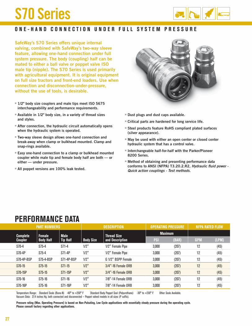
SafeWay’s S70 Series offers unique internal valving, combined with SafeWay’s two-way sleeve feature, allowing one-hand connection under full system pressure. The body (coupling) half can be mated to either a ball valve or poppet valve ISo male tip (nipple). The S70 Series is used primarily with agricultural equipment. It is original equipment on full size tractors and front-end loaders. use when connection and disconnection-under-pressure, without the use of tools, is desirable.
S70 Series
part numBers desCriptiOn Operating pressure nFpa rated FLOw
Complete Coupler
Female Body half
maletip half Body size
thread size and description
maximum
psi (Bar) gpm (Lpm)
S70-4 S75-4 S71-4 1/2" 1/2" Female Pipe 3,000 (207) 12 (45)
S70-4P S75-4 S71-4P 1/2" 1/2" Female Pipe 3,000 (207) 12 (45)
S70-4P-BSP S75-4-BSP S71-4P-BSP 1/2" G 1/2" BSPP Female 3,000 (207) 12 (45)
S70-15 S75-15 S71-15 1/2" 3/4"-16 Female ORB 3,000 (207) 12 (45)
S70-15P S75-15 S71-15P 1/2" 3/4"-16 Female ORB 3,000 (207) 12 (45)
S70-16 S75-16 S71-16 1/2" 7/8"-14 Female ORB 3,000 (207) 12 (45)
S70-16P S75-16 S71-16P 1/2" 7/8"-14 Female ORB 3,000 (207) 12 (45)
Temperature Range: Standard Seals (Buna-N) -40° to +250° F Standard Body Poppet Seal (Polyurethane) -30° to +230° F Other Seals Available. Vacuum Data: 27.4 inches Hg. both connected and disconnected — Poppet valved models in all sizes (P suffix).
pressure rating (max. Operating pressure) is based on non-pulsating, Low Cycle applications with essentially steady pressure during the operating cycle. please consult factory regarding other applications.
perFOrmanCe data

w w w . s a f e w a y h y d . c o m | 4 0 4 0 n o r e x d r i v e | c h a s k a , m n 5 5 3 1 8 | 8 0 0 . 2 2 2 . 1 1 6 928
PRESSURE DROP VS. FLOW S70 Series
FLOW (GPM)
PRES
SURE
DRO
P (P
SID)
1 2 3 4 5 6 8 10 20 30 40 50 60 80 100
1
2
3
4 5 6
8 10
20
30
40 50 60
80 100
MIL-H-5606 OIL 100˚ F
= RATED FLOW
COnneCt-under-pressure agriCuLturaL O.e.m. COupLings
EG
FTIP
ACONNECTED
BBODY
Saf
eWay
USA
H
D
C
Saf
eWay
USA
EG
FTIP
ACONNECTED
BBODY
Saf
eWay
USA
H
D
C
Saf
eWay
USA
EG
FTIP
ACONNECTED
BBODY
Saf
eWay
USA
H
D
C
Saf
eWay
USA
S70
SERI
ES
dimensiOns (inches)
Complete Coupler number
Overall Length Body Length diameter wrench Flat diameter tip Length diameter hex
a B C d e F g h
S70-4 4.34 3.39 1.50 .93 1.06 1.94 1.22 1.06
S70-4P 4.34 3.39 1.50 .93 1.06 1.96 1.22 1.06
S70-4P-BSP 4.34 3.39 1.50 .93 1.06 1.96 1.22 1.06
S70-15 4.34 3.39 1.50 .93 1.06 1.94 1.22 1.06
S70-15P 4.34 3.39 1.50 .93 1.06 1.96 1.22 1.06
S70-16 4.34 3.39 1.50 1.00 1.06 1.94 1.22 1.06
S70-16P 4.34 3.39 1.50 1.00 1.06 1.96 1.22 1.06
See pages 32 and 33 for accessories to the S70 Series.
29
B a L L v a L v e a n d p O p p e t v a L v e m O d e L s
ISO AGRICULTURAL TIPS
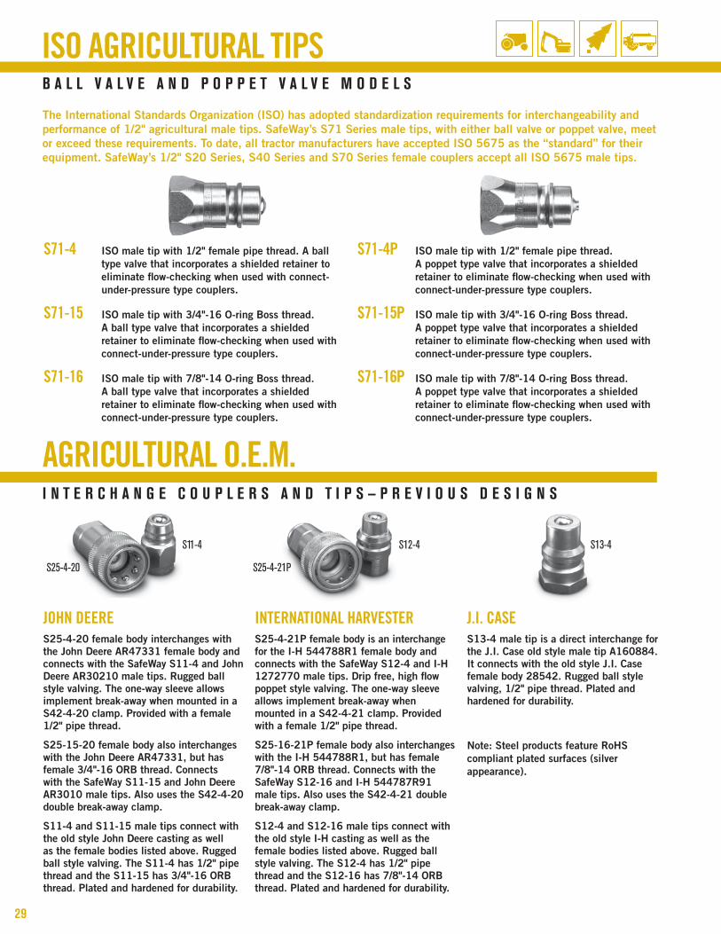
The International Standards organization (ISo) has adopted standardization requirements for interchangeability and performance of 1/2" agricultural male tips. SafeWay’s S71 Series male tips, with either ball valve or poppet valve, meet or exceed these requirements. To date, all tractor manufacturers have accepted ISo 5675 as the “standard” for their equipment. SafeWay’s 1/2" S20 Series, S40 Series and S70 Series female couplers accept all ISo 5675 male tips.
S71-4 ISo male tip with 1/2" female pipe thread. A ball type valve that incorporates a shielded retainer to eliminate flow-checking when used with connect-under-pressure type couplers.
S71-15 ISo male tip with 3/4"-16 o-ring boss thread. A ball type valve that incorporates a shielded retainer to eliminate flow-checking when used with connect-under-pressure type couplers.
S71-16 ISo male tip with 7/8"-14 o-ring boss thread. A ball type valve that incorporates a shielded retainer to eliminate flow-checking when used with connect-under-pressure type couplers.
S71-4P ISo male tip with 1/2" female pipe thread. A poppet type valve that incorporates a shielded retainer to eliminate flow-checking when used with connect-under-pressure type couplers.
S71-15P ISo male tip with 3/4"-16 o-ring boss thread. A poppet type valve that incorporates a shielded retainer to eliminate flow-checking when used with connect-under-pressure type couplers.
S71-16P ISo male tip with 7/8"-14 o-ring boss thread. A poppet type valve that incorporates a shielded retainer to eliminate flow-checking when used with connect-under-pressure type couplers.
JOHN DEERE S25-4-20 female body interchanges with the john Deere Ar47331 female body and connects with the SafeWay S11-4 and john Deere Ar30210 male tips. rugged ball style valving. The one-way sleeve allows implement break-away when mounted in a S42-4-20 clamp. provided with a female 1/2" pipe thread.
S25-15-20 female body also interchanges with the john Deere Ar47331, but has female 3/4"-16 orb thread. connects with the SafeWay S11-15 and john Deere Ar3010 male tips. Also uses the S42-4-20 double break-away clamp.
S11-4 and S11-15 male tips connect with the old style john Deere casting as well as the female bodies listed above. rugged ball style valving. The S11-4 has 1/2" pipe thread and the S11-15 has 3/4"-16 orb thread. plated and hardened for durability.
INTERNATIONAL HARVESTERS25-4-21p female body is an interchange for the I-h 544788r1 female body and connects with the SafeWay S12-4 and I-h 1272770 male tips. Drip free, high flow poppet style valving. The one-way sleeve allows implement break-away when mounted in a S42-4-21 clamp. provided with a female 1/2" pipe thread.
S25-16-21p female body also interchanges with the I-h 544788r1, but has female 7/8"-14 orb thread. connects with the SafeWay S12-16 and I-h 544787r91 male tips. Also uses the S42-4-21 double break-away clamp.
S12-4 and S12-16 male tips connect with the old style I-h casting as well as the female bodies listed above. rugged ball style valving. The S12-4 has 1/2" pipe thread and the S12-16 has 7/8"-14 orb thread. plated and hardened for durability.
J .I . CASES13-4 male tip is a direct interchange for the j.I. case old style male tip A160884. It connects with the old style j.I. case female body 28542. rugged ball style valving, 1/2" pipe thread. plated and hardened for durability.
note: Steel products feature rohS compliant plated surfaces (silver appearance).
AGRICULTURAL O .E .M .i n t e r C h a n g e C O u p L e r s a n d t i p s — p r e v i O u s d e s i g n s
S11-4 S12-4 S13-4
S25-4-21PS25-4-20

w w w . s a f e w a y h y d . c o m | 4 0 4 0 n o r e x d r i v e | c h a s k a , m n 5 5 3 1 8 | 8 0 0 . 2 2 2 . 1 1 6 930
Fae49-56-4Allows Connection of a SafeWay FF491-6 or FFE491-4 or other 1/2” ISO 16028 Male Tip to a SafeWay S56, S20, S40 Series or other 1/2” ISO 5675 Female Body.
s25-4-5Allows Connection of an International Harvester (Old Style) Male Tip to a John Deere Cone (Old Style) Female Body.
Fae56-49-4Allows Connection of a SafeWay S56, S70 Series or other 1/2” ISO 5675 Male Tip to a SafeWay FF495-6 or FFE495-4 or other 1/2” ISO 16028 Female Body.
s25-4-6Allows Connection of a SafeWay S70 Series or other 1/2” ISO 5675 Male Tip to a J.I. Case (Old Style) Female Body.
s25-4-1Allows Connection of a SafeWay S70 Series or other 1/2” ISO 5675 Male Tip to a John Deere (Old Style) Female Body.
s25-4-7Allows Connection of an International Harvester (Old Style) Male Tip to a SafeWay S20, S40, S70 Series or other 1/2” ISO 5675 Female Body.
s25-4-2Allows Connection of a SafeWay S70 Series or other 1/2” ISO 5675 Male Tip to an International Harvester (Old Style) Female Body.
s25-4-7dAllows Connection of an International Harvester (Old Style) Male Tip to a New Style John Deere Female Body.
s25-4-3Allows Connection of a John Deere Cone (Old Style) Male Tip to a SafeWay S20, S40, S70 Series or other 1/2” ISO 5675 Female Body.
s25-4-8Allows Connection of a J.I. Case (Old Style) Male Tip to a SafeWay S20, S40, S70 Series or other 1/2” ISO 5675 Female Body.
s25-4-3dAllows Connection of a John Deere Cone (Old Style) Male Tip to a (New Style) John Deere ISO Casting or ISO 5675.
s25-4-9Allows Connection of a John Deere Cone (Old Style) Male Tip to a J.I. Case (Old Style) Female Body.
s25-4-4Allows Connection of a John Deere Cone (Old Style) Male Tip to an International Harvester (Old Style) Female Body.
s25-4-10Allows Connection of a J.I. Case (Old Style) Male Tip to a John Deere (Old Style) Female Body.
COUPLER ADAPTERSi n t e r C O n n e C t n O n - C O m p a t i B L e t i p s & B O d i e s

31
S80 Seriesp n e u m a t i C a r O - 2 1 0 i n t e r C h a n g e
S82 Series
Operating pressure dimensiOns (inches) thread size npt
part number part name Body size
maximum Length diameter wrench hex
psi (Bar) a B C d
S801-2M Tip 1/4" 300 (20) 1.62 — .56 1/4" Male
S801-2F Tip 1/4" 300 (20) 1.50 — .62 1/4" Female
S805-2 Body 1/4" 300 (20) 1.83 .88 .75 1/4" Female
Operating pressure dimensiOns (inches) thread size npt
part number part name Body size
maximum Length diameter wrench hex
psi (Bar) a B C d
S821-2M Tip 1/4" 300 (20) 1.70 — .56 1/4" Male
S821-2F Tip 1/4" 300 (20) 1.49 — .62 1/4" Female
S821-3M Tip 3/8" 300 (20) 1.91 — .69 3/8" Male
S821-3F Tip 3/8" 300 (20) 1.68 — .81 3/8" Female
S821-3-2M Tip 3/8" 300 (20) 1.88 — .68 1/4" Male
S821-3-2F Tip 3/8" 300 (20) 1.62 — .62 1/4" Female
S825-2M Body 1/4" 300 (20) 2.17 .95 .69 1/4" Male
S825-2 Body 1/4" 300 (20) 2.14 .95 .69 1/4" Female
S825-3M Body 3/8" 300 (20) 2.41 1.19 .94 3/8" Male
S825-3 Body 3/8" 300 (20) 2.43 1.19 .94 3/8" Female
D
TIP A
BODY A
C
D
C
B
FEMALETHREAD
MALE THREAD
DFEMALE THREAD
BODY A
TIP A
C
B
C DMALE
THREAD
s80 series—arO 210 series pneumatic interchange (manual Connect)
s82 series—pneumatic industrial interchange (manual Connect)
p n e u m a t i C i n d u s t r i a L i n t e r C h a n g e
S80
SERI
ESS8
2 SE
RIES

w w w . s a f e w a y h y d . c o m | 4 0 4 0 n o r e x d r i v e | c h a s k a , m n 5 5 3 1 8 | 8 0 0 . 2 2 2 . 1 1 6 932
p r O v i d i n g Y O u w i t h a L L Y O u r h Y d r a u L i C C O u p L i n g n e e d s
ACCESSORIES
DUST CAPS & DUST PLUGSProtective dust caps and dust plugs are available in rubber or metal in a variety of sizes. They should be used whenever possible to help reduce contamina-tion of the hydraulic system and improve service life of the body half (coupling) and the mating tip half (nipple). A molded combination cap/plug is now available. Please refer to the accessories chart on page 33 with your specific requirement.
BREAk-AWAy CLAMPSSafeWay’s heavy-duty double break-away clamps allow one-hand connection when used with two-way sleeve style agricultural quick couplings. They also allow implement break-away when used with either one-way or two-way sleeve agricultural designs. Double break-away clamps are available for 3/8" and 1/2" body size agricultural quick couplings.
Bulkhead mounting rings provide for bulkhead mounting (up to 1/8" thick) of our S40 Series and S70 Series female couplers. Please refer to the accessories chart on page 33 with your specific requirement.
REPLACEMENT SEAL kITSBoth replacement seal kits and individual O-rings and back-up rings are available. Leakage between the female body half (coupling) and the male tip half (nipple) is an indication that the body O-ring needs replacement.
Field repair kits that include the body seal, a new poppet assembly and installation instructions are available for various couplings. Please refer to the accessories chart on page 33 with your specific requirement.
REDUCER BUSHINGSReducer Bushings downsize the 1/2" female pipe thread to either a 3/8" or 1/4" female pipe thread. The S4-2 reduces a 1/2" pipe thread to 1/4". The S4-3 reduces a 1/2" pipe thread to a 3/8".
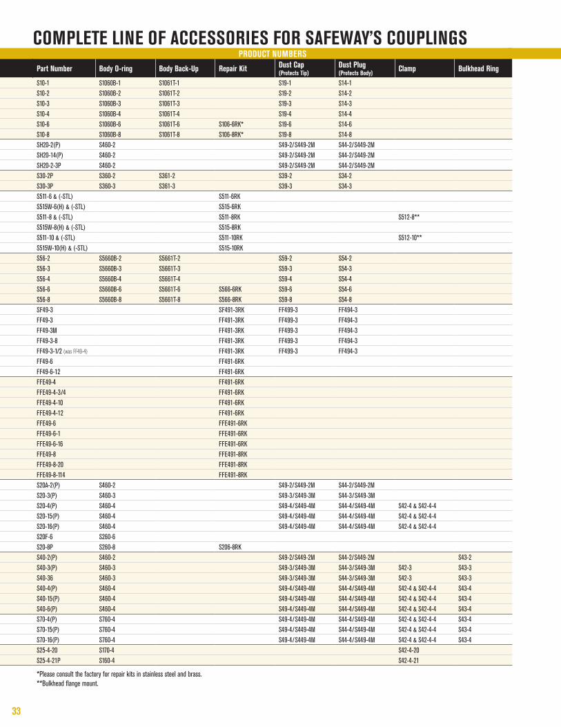
33
COmpLete Line OF aCCessOries FOr saFewaY’s COupLingsprOduCt numBers
part number Body O-ring Body Back-up repair kit dust Cap (protects tip)
dust plug (protects Body)
Clamp Bulkhead ring
S10-1 S1060B-1 S1061T-1 S19-1 S14-1S10-2 S1060B-2 S1061T-2 S19-2 S14-2S10-3 S1060B-3 S1061T-3 S19-3 S14-3S10-4 S1060B-4 S1061T-4 S19-4 S14-4S10-6 S1060B-6 S1061T-6 S106-6RK* S19-6 S14-6S10-8 S1060B-8 S1061T-8 S106-8RK* S19-8 S14-8SH20-2(P) S460-2 S49-2/S449-2M S44-2/S449-2MSH20-14(P) S460-2 S49-2/S449-2M S44-2/S449-2MSH20-2-3P S460-2 S49-2/S449-2M S44-2/S449-2MS30-2P S360-2 S361-2 S39-2 S34-2S30-3P S360-3 S361-3 S39-3 S34-3S511-6 & (-STL) S511-6RKS515W-6(H) & (-STL) S515-6RKS511-8 & (-STL) S511-8RK S512-8**S515W-8(H) & (-STL) S515-8RKS511-10 & (-STL) S511-10RK S512-10**S515W-10(H) & (-STL) S515-10RKS56-2 S5660B-2 S5661T-2 S59-2 S54-2S56-3 S5660B-3 S5661T-3 S59-3 S54-3S56-4 S5660B-4 S5661T-4 S59-4 S54-4S56-6 S5660B-6 S5661T-6 S566-6RK S59-6 S54-6S56-8 S5660B-8 S5661T-8 S566-8RK S59-8 S54-8SF49-3 SF491-3RK FF499-3 FF494-3FF49-3 FF491-3RK FF499-3 FF494-3FF49-3M FF491-3RK FF499-3 FF494-3FF49-3-8 FF491-3RK FF499-3 FF494-3FF49-3-1/2 (was FF49-4) FF491-3RK FF499-3 FF494-3FF49-6 FF491-6RKFF49-6-12 FF491-6RKFFE49-4 FF491-6RKFFE49-4-3/4 FF491-6RKFFE49-4-10 FF491-6RKFFE49-4-12 FF491-6RKFFE49-6 FFE491-6RKFFE49-6-1 FFE491-6RKFFE49-6-16 FFE491-6RKFFE49-8 FFE491-8RKFFE49-8-20 FFE491-8RKFFE49-8-114 FFE491-8RKS20A-2(P) S460-2 S49-2/S449-2M S44-2/S449-2MS20-3(P) S460-3 S49-3/S449-3M S44-3/S449-3MS20-4(P) S460-4 S49-4/S449-4M S44-4/S449-4M S42-4 & S42-4-4S20-15(P) S460-4 S49-4/S449-4M S44-4/S449-4M S42-4 & S42-4-4S20-16(P) S460-4 S49-4/S449-4M S44-4/S449-4M S42-4 & S42-4-4S20F-6 S260-6S20-8P S260-8 S206-8RKS40-2(P) S460-2 S49-2/S449-2M S44-2/S449-2M S43-2S40-3(P) S460-3 S49-3/S449-3M S44-3/S449-3M S42-3 S43-3S40-36 S460-3 S49-3/S449-3M S44-3/S449-3M S42-3 S43-3S40-4(P) S460-4 S49-4/S449-4M S44-4/S449-4M S42-4 & S42-4-4 S43-4S40-15(P) S460-4 S49-4/S449-4M S44-4/S449-4M S42-4 & S42-4-4 S43-4S40-6(P) S460-4 S49-4/S449-4M S44-4/S449-4M S42-4 & S42-4-4 S43-4S70-4(P) S760-4 S49-4/S449-4M S44-4/S449-4M S42-4 & S42-4-4 S43-4S70-15(P) S760-4 S49-4/S449-4M S44-4/S449-4M S42-4 & S42-4-4 S43-4S70-16(P) S760-4 S49-4/S449-4M S44-4/S449-4M S42-4 & S42-4-4 S43-4S25-4-20 S170-4 S42-4-20S25-4-21P S160-4 S42-4-21
*Please consult the factory for repair kits in stainless steel and brass. **Bulkhead flange mount.

w w w . s a f e w a y h y d . c o m | 4 0 4 0 n o r e x d r i v e | c h a s k a , m n 5 5 3 1 8 | 8 0 0 . 2 2 2 . 1 1 6 934
________________________________________________________________________________________
________________________________________________________________________________________
________________________________________________________________________________________
________________________________________________________________________________________
________________________________________________________________________________________
________________________________________________________________________________________
________________________________________________________________________________________
________________________________________________________________________________________
________________________________________________________________________________________
________________________________________________________________________________________
________________________________________________________________________________________
________________________________________________________________________________________
________________________________________________________________________________________
________________________________________________________________________________________
________________________________________________________________________________________
________________________________________________________________________________________
________________________________________________________________________________________
________________________________________________________________________________________
________________________________________________________________________________________
________________________________________________________________________________________
________________________________________________________________________________________
________________________________________________________________________________________
________________________________________________________________________________________
________________________________________________________________________________________
________________________________________________________________________________________
________________________________________________________________________________________
________________________________________________________________________________________
nOtes

4 0 4 0 N o r e x D r i v e | C h a s k a , M N 5 5 3 1 8�p h o N e : 9 5 2 . 4 6 6 . 6 2 2 0 f a x : 9 5 2 . 4 6 6 . 6 2 1 9
1 . 8 0 0 . 2 2 2 . 1 1 6 9 w w w . s a f e w a y h y D . C o M | M a i l @ s a f e w a y h y D . C o M
p r o D U C T C a T a l o G 2 1 0 0 (rev. G)
©2011, safeway hydraulics, inc. printed in the U.s.a.