query processing in tertiary memory databases
TRANSCRIPT
Query Processing in Tertiary Memory Databases*
Sunita Sarawagi
Comput,er Science Division, 396 Soda. Hall IJniversity of California, Berkeley, CA 94720, USA
sunitaQcs.berkeley.edu
Abstract
Wit,11 rapid increase in the number of applica- tions thal, require access to large amounts of da,ta., it is becoming increasingly important for tla.ta.l~aac syst,ems t,o ha.ndle tert,ia.ry storage dcviccs. The cha.ra.ctcristics of tertia.ry mem- ory devices a.re very differ& from secondary storag;c devices that, conventional database sysletr~ a.re designed for. This requires new approa.ches to ma.naging data, loca.tion and movcmcnt, together with query execution in a unilied framework. In this paper WC present methods of scheduling queries, caching and controlling the order of da.ta, rct,rieva.l for eff~- c&1. operation in a tertia.ry rncniory cnviron- nienl. Wc show how careful interspersing of queries and informed cache management can achieve rema.rkable reductions in access time compared 1x1 conventional methods. Our al- goril(hms use a few model pa.rameters for each tertiary memory device and are thus designed to be portable across a wide variety of tert,ia.ry memory devices and da,tnhase t,ypes. We arc
extending the PoS’TGR.ES database system to implements t,he new query processing strate- gics. Jnit,ial mea.surements on the prototype yield impressive results.
*This research was sponsored by NSF Grant, IRI-9107455, AR0 Grant, DAAI,O3-91-Q-0183, and DARPA Contract. DADT63-92-C-0007. Additional support was provided by the IJniversity of Californiaand Digital Equipment Corporation un- tlcr Sequoia 2000 research grant #1.243.
l’ermission to copy with.out ,fcc all or part of this materia.1 is grnntrd provided that the copies arc n,ot ma.de OT distributed fOT
dirrct con~mrrcia.1 advanta.ge, th.e VLDB copyrigh.t notice and Ibe titlr 0.f thr publication an.d its dnte appear, and notice is giwn thw.t ropying is by permission of the Very Large Data Rase l~:l,dowmcnt. l’o copy olherwinr, OT to wprblish, rcquirea a fee aad/oT special permission from the Endowmeat.
Proceedings of the Zlst VLDI3 Conference Zurich, Swiztrrland, 1995
1 Introduction
Applications manipulating large volumes of data are growing in number: earth observation systems, his- torical data base systems, statistical data collections a.nd image and video stora.ge systems are a few exam- ples. There is increa.sing consensus amongst database researchers [St0911 [CHL93] [Se1931 [Moh93] regarding tIhe need of a, database controlled tertiary memory for storing massive a.ruounts of data.
A major limit,ation of traditional DBMSs is the as- sumption tha.t all data resides on magnetic disk or main memory. Therefore all optimization decisions are oriented towa.rds this technology. Tertiary mem- ory, if used at all, functions only as an archival stor- age system to be written once and rarely read. Some da.tabase syst,ems [Isa931 a.llow data to be stored on tertiary memory, but they do so by using a file system to get transparent access to data and store only meta- data information in the database system. This means that the tertiary memory is not under direct control of the database system. One important exception is POSTGR.ES [Ols92]. POSTGRES includes a Sony opti- cal jukebox [Son891 as an additional level of the stor- age hierarchy. The POS’T’GRF,S storage manager can move data. transparent,ly between a disk cache and the jukebox using a. LRU replacement strategy. While this prototype implements the storage manager for tertiary memory, a lot of issues related to tertia.ry memory spe- cific performance optimization still remain unexplored.
Tertiary memory devices pose a challenge to database designers because their performance cha.rac- tedstics are very different from those of magnetic disks. A typical device consists of a large number of storage units, a few read-writ,e drives and even fewer robot arms to switch the stora.ge units between the shelves and the drives. A storage unit, which we generically call a platter, is either a ta.pe cartridge or an optical disk. In Table I we compare several tertiary mem- ory devices with a magnetic disk. The characteristics shown a,rc exchange time (time to unload one stor- age unit from the drive and then load a uew unit and
585
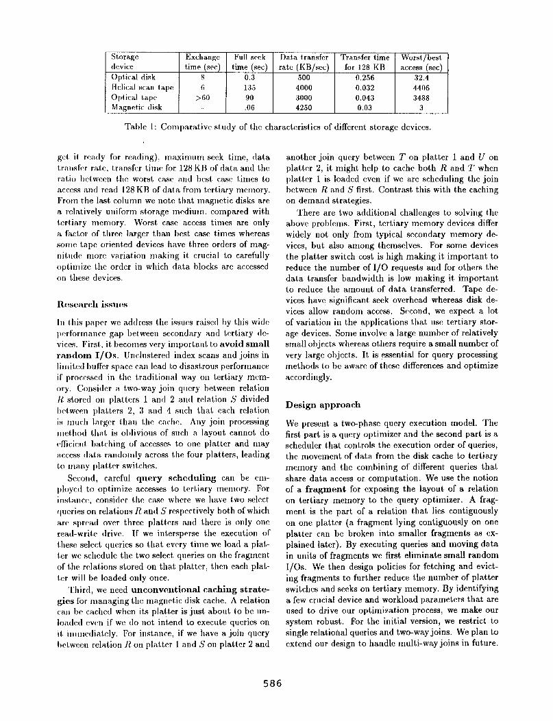
Stora.gc Exchauge l?ull seek Da.1.a tra.nsfer Transfer time Worst/best device time (set) time (set) rate (KB/sec) for 128 KB access (set) Opf,ical disk 8 0.3 500 0.256 32.4 Helical scan t,a.l>c 6 135 4000 0.032 4406 Optic-al tape >GO 90 3000 0.043 3488 Magntdic disk .06 4250 0.03 3
T&le 1: Conlparativc study of the chara,cteristics of different storage devices.
get ii rca.dy for reading), maximum seek time, data transfr~ ra.l.c, tra.nsfcr time for 128 KB of data and the ratio btbween the worst case nnd best, ca.sc t.imes to access a.ntl rca.d 128 K13 of data from tertiary memory. From i,he last column we not,c that magnetic disks arc a. ralatively uniform si#ora.ge medium, compared with tertiary memory. Worst case access times are only a fa.ctor of three larger than best, ca.se times whereas some tape oriented devices have three orders of mag- nitudc more variat,ion ma.king it crucia.1 to carefully optimize the order in which data blocks are accessed on these devices.
R.f?scarch issues
In t,his pa.pcr WC a,dtlrrss thr issurs raised by this wide pc‘rforlna.ncc gap I&ween secondary nnd tprt,iary de- vices. First., it becomes very importa.nt to twoid small random I/OS. Unclusteretl index scans and joins in linlitcd buffer space can lead to disa.strous performance if prowssctl in the tra.ditionaI wa.y on terlia.ry mem- ory. Consider a. t,wo-way join q~rc>ry between relal,ion 1~ stored on platters 1 a,ntl 2 and rela.tion S divided bc%t,wce,n pla,tt,ers 2, 3 a.nd 4 such t,hat each relat,ion is 1nuc11 larger (,ha.rr the ca.c:ht:. Any join processing 111cthot1 that is oblivious of such a. layout ca,nnot do dicirntI batching of a.ccesses to one platter and ma.y R.CCCSS tla,ta. ra.ndomly a.cross the four pla.tters, leading to many pla.tter switches.
Second, careful query scheduling can be cm- ploycd to optimize accesses t#o tcrt(ia.ry memory. For iust,nnce, consitlr>r the ra.se where we ha.vc two select, queries on rela.tions II and S respectively both of which a.rC spud over three platters and there is only one read-write drive. If we inbersperse t#hc execution of these select queries so that every time we load a plat- tcr we schedule the two select queries on the fra.gment of the rrlai,ions stored on that platter, then each plat- ter will be loaded only once.
Third, we need unconventional caching strate- gies for managing the ma.gnetic disk cache. A reMion ca.rr be ca.ched when its plat,ter is just about, t,o be un- lontlcd rvcn if we do not, intend to execute queries on it immedia~tely. For inst#ance, if we have a. join query I~ctwccn relation h’ on pla.tter 1 and S OII platter 2 and
another join query bet,ween T on platter 1 and U on platter 2, it might help to cache both R and T when platter 1 is loaded even if we are scheduling the join between II and S first. Contrast this with the caching on demand stra.tegies.
There a,re two additiona. challenges to solving t,he above problems. First, tert.iary memory devices differ widely not only from typical secondary memory de- vices, but also among themselves. For some devices the platter switch cost is high making it important to reduce the number of I/O requests and for others the data transfer bandwidth is low making it important to reduce the amount of data transferred. Tape de- vices have significant, seek overhead whereas disk de- vices allow random access. Second, we expect a lot of va.riation in the applicat#ions that use tertiary stor- a.ge devices. Sorrre involve a large number of relatively small objects whereas others require a small number of very large object,s. It is essent,ial for query processing methods to be aware of these differences and optimize accordingly.
Design approach
We present a two-phase query execution model. The first part is a query optimizer and the second part is a scheduler that controls the execution order of queries, the movement of data. frorn the disk cache to tertia.ry memory a.nd the combining of different, queries that sha.re data Access or computation. We use the notion of a fragment for exposing the layout of a relation on tertiary memory to the query optimizer. A frag- ment is the part, of a relation that lies contiguously on one platter (a fragment lying contiguously on one platter can be broken into sma.llcr fragments as ex- plained later). By executing queries and moving data in units of fragments we first eliminate small random I/OS. We then design policies for fetching and evict- ing fra.gments to further reduce the number of platter switches and seeks on tertiary memory. By identifying a few crucial device and workload parameters that are used to drive our optimization process, we make our system robust. For the initial version, we restrict to single relatiohal queries and two-way-joins. We plan to extend our design to handle multi-wa.y joins in future.
586
asynchronous i data movement
Execution Unit :1/1
Optical disk or tape : tertiary memory ------------ _______I
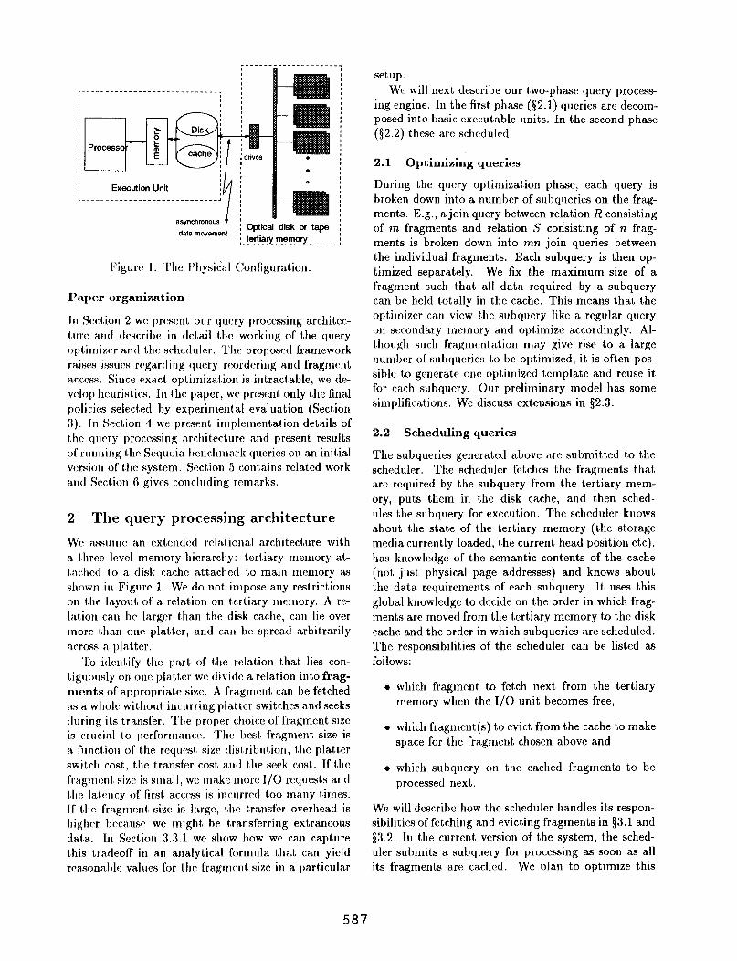
Figure 1: The Physical Configuration.
Paper organization
In Section 2 we present our query processing architec- ture and describe in detail the working of the query optimizer and the scheduler. The proposed fra,mework raises issaf~ qartling query reordering and fragment acc(‘ss. Since exact, optimiza.t,ion is intractable, we de- velop heuristics. In the pa,per, WC present. only the final policies selectred by experimentBid eva.lua.tion (Section 3). III Section 4 we present irllpl(:lucntat,ion deMs of lhe query processing a,rchit,fcture and present results of ruuning the Sequoia. benchma.rk queries on an initial version of i,lw sy&em. ScctAon 5 cont,ains r&ted work a.nd SecGon 0 gives concluding remarks.
2 The query processing architecture
We assu~ne an extcndcd re:lalional architecture with a. l,hree level memory hierarchy: tertiary memory at- t~~.chcd to a disk cache at,ta.chctl t,o main memory as shown in Figure 1. We do not impose any resbrict(ions on the layoul~ of a, relation on terbiary inelnory. A re- Iation can hc larger than the disk cache, ca.n lie over rnore t,han one platter, and can be spread arbitrarily across a. pla.tter.
‘1’0 itlcn18ify the part of the reMion that lies con- t.iguously on one platter we divide a relation into frag- ments of appropriate size. A fra.gment can be fetched as a whole without. incurring pla.tter switches and seeks during its transfer. The proper choice of fragment size is crucial i,o performa.nce. ‘I’hc best fra,gment size is a firnctioii of the request, size dist,ribution, the pla.tAer swibch cost, the f,ransfer cost and the seek cost. If f(ho fragmc>nt. sixc is sma.l1, we make nlore l/O requests and L~IC lal,c>ncy of first access is incurred too ma,ny times. If the fra.gmcnt8 size is Ia.rge, t,hc trsnsfer 0verhea.d is
higher because we might, be t,ra,nsferring extraneous data. In Section 3.3.1 we show how we can capture this bra.deoff in an analytical formula tha.t can yield rcasonablc values for the fragment size in a particular
setup. We will next, describe our two-phase query process-
ing engine. In the first phase ($2.1) queries are decom- posed into basic executa.ble units. In the second phase ($2.2) these are scheduled.
2.1 Optimizing queries
During the query optimization phase, each query is broken down into a number of subqueries on the frag- ments. E.g., a join query between relation R consisting of m fragments and relation S consisting of n frag- ments is broken down into mn join queries between the individual fragments. Each subquery is then op- timized separately. We fix t,he maximum size of a fragment such tha.t all data required by a subquery can be held totally in the cache. This means that the optimizer can view the subquery like a regular query on secondary memory and optimize accordingly. Al- though such fragmentation may give rise to a large number of subqueries to be optimized, it is often pos- sible to generate one optimized template and reuse it for each subquery. Our prelimina.ry model has some simplifications. We discuss extensions in $2.3.
2.2 Scheduling queries
The subqueries generated above are submitted to the scheduler. The scheduler fetches the fragments that are required by the subquery from the tertiary mem- ory, puts them in the disk cache, and then sched- ules the subquery for execution. The scheduler knows a.bout the state of the tertiary memory (the storage media currently loa.ded, the current head position etc), has knowledge of the semantic contents of the cache (not, just, physical page addresses) and knows about the data requirements of each subquery. It uses this g1oba.l knowledge to decide on the order in which frag- rnent,s arc moved from the tertiary memory to the disk ca,che and the order in which subqueries are scheduled. The responsibilities of the scheduler can be listed as follows:
l which fragment to fetch next from the tertiary memory when t#he I/O unit becomes free,
l which fragment(s) to evict from the cache to make spa.ce for the fmgment chosen above and
l which subquery ou the cached fragments to be processed next.
WC will describe how the scheduler handles its respon- sibilities of fetching and evicting fragments in $3.1 and $3.2. In the current version of the system, the sched- uler submits a subquery for processing as soon as all its fragments are ca,ched. We plan to optimize this
587
part of the scheduler to do multiple query optimiza- tion betwtcn the subqucries.
2.3 Extensions to the model
A number of extensions were mado i,o this mode1 of quc\ry processing to ha.ndlc relations wit,h large object,s, t#o ,410~ more efficient use of indexing and to avoid redundant processing. The important ones are listed hclow:
l Da,tabases often have images and video clips which are stored as large objects. In our model, we a.ssume tShat ea.& large object is stored as a spparatc fragment and a select query on a rela- tion wii.11 one of the a.ttributes a large object, is c\xccut~rtl in two phasrs. In the first stage, we do a select on the basf~ relation, get, a list of la.rgc ol)jccts to bc fetched and fetch (#hem in any order in t#he second pha.se.
l We a.ssnme 1.ha.t ra,ch fra.gment has it,s own index. Depending on the size of the index, the DRA can choose bo store it, either on ma.gnetic disk or tar- tia.ry memory. When doing an index scan ou a re- la.tion, it might help to scan t#he index trees first, fintl out which fragincnts contain qlli~lifyillg tuples and fetch only t,hosc fra.gll1c~nt.s la.tcr. This will help remove random I/OS which can be wasteful ou t#ertia.ry memory.
l Although brca,king queries into independent sub- queries is fa.vornble for reducing I/O costs to ter- tiary nlcmory, we n1a.y 1)il.y higher processing cost for SOIIIC queries. For instance, in a hash join if 10le probe relation is broken into 71. fra,gments, then t.he hnsh t,a.ble for each fra.ginent of the build re- la.tion has to bc construct,4 n times. To reduce this overhea.d, WC will modify our scheduler to or- der the execution of subquerics so 1ha.t whenever possible the hash table can be sha.red across mul- tiplc subqueries, This will be treal,ed as a pa.rt, of 1,1lc genera.1 multiple query optilnization to be handled by the scheduler.
l For some queries t,he order of the result tuples is importa.nt and rxcAc.utCing subqucries indepen- &ntly is not possible. In our initial model, we are ignoring queries tShnt require sorted results.
3 Scheduling policies
3.1 Fragment fetch policies
The scheduler ha,s a pool of (*asks which arc tither ISwo-way joins or select queries on a. single fragment, or fdch rc~rluest, for a list of lnrge o1)ject.s. For an index scan on A fragment with the index residing on tertiary
memory, we view the index tree as another fragment and the index scan query as a join between the in- dex and the base fragment. Implicitly, this collection of plans forms a query graph. where the nodes denote the fragments and the edges denote the joins between two fragments. In this graph, an edge between two nodes implies that both the fragments represented by these nodes must reside in the cache together for the query to be processed. Fragments which do not join with any other fragment will be represented as isolated nodes. We are given a limited amount of disk cache, typically, less than the sum of the sizes of the frag- ments queried. The query graph keeps on changing as queries get completed and new queries arrive.
At any time, there is a pool of subqueries waiting t,o be executed, ea.ch of t,hese subqueries requires one or more fragments to be present in the cache for pro- cessing. Of the fra,gments required, some fragments are already in the disk ca.che and others need to be fetched from t#ertiary stora,ge. Of these fragments, some reside on platters iShat are currently loaded and others reside on unloaded platters. Our objective is to migrate these fragments to and from tertiary memory and the disk cache so as to minimize the total time spent doing I/O on teri,ia.ry memory.
The above on-line problem is NP-complete since an off-line restriction of the formulation has been shown to be NP-complete in [MKYSl]. Hence, an algorithm that, finds the optimal solution is’likely to be too ex- pensive to be useful. Consequently, we use a number of heuristics for reducing the search space.
Design Methodology
The design of a good heuristic for fetching fragments is made challenging by the large number of parameters, c.g., cache size, number of users, size of fragments, platter switch cost,, data. transfer cost and seek cost. In order to control the complexity, we designed the algorithm in mu1Gple stages. We first started with an algorithm that, minimizes transfer cost, then we added the platter switch cost to the cost model and refined the algorithm to minimize the sum of the plat- ter switch and transfer cost,. Finally, we incorporated seek cost into the cost model by refining the algorithm. For brevity we present the final resulting set of heuris- tics. We used extensive simulation to aid us in the search for good heuristics.
Optimizing for transfer cost
We first started with the case where the platter switch and seek overhead is zero and minimizing I/O time is equivalent t(o minimizing the total bytes transferred. Even this problem is NP-complete. Hence, we tried out different, heuristics for deciding on the order in
588
which fragments slmultl be fetched from tertiary mem- ory. Some of the important heuristics were: fetch frag- ment with the largest number of queries next; fetch the smallest, fragment next; and fetch fragment that joins with the maximum number of cached fragments next. Amongst these and others that we tried, we found that the policy which performed the best overall was:
POLICY-~: Fetch fragment that joins with the largest sum of sizes of cached fragments. Re- solve ties by choosing fragment that has the greater number of queries.
Incorporating platter switch cost
To ena.ble POLICY-~ to optimize for both platter switches and transfers we refined it as follows: As long a9 there are fragments on the loaded platters that join wibh the cached fragments we fetch fragments from the loadrd platters. When there are no more fragments of that type, we could either fetch fragments from the loaded platters or load a new platter that, contains fragments which join with the cached fragments using the order given by POLICY-~. This decision depends on the amount of cache space available. If the cache space is large so that we do not have to evict active fragments from the cache, we call fetch fragments from the loadetl platters, or else, we need to switch platters. The modified policy is given below:
POLICY-2
Fetch next fragment that joins with the cached fragmentIs and resides on a loaded platter.
Jf no such fragment, If (“no room in cache”)
Switch to an unloaded platter choosing platter with fragments that join with maximum cached fragments
Fetch fragment from the chosen platter Else
Fetch fragment from the loaded platters If no fragment on the loaded platters,
switch an unloaded platter choosing platter with maximum queries
We need a method to estimate if there is “room in cache” for fragments on the loaded platters that do not join with the cached fragments. Clearly, just using the total size of the cache for estimating this predicate is not sufficient because the current set of active fragments in the cache and the fragments that they join with play an important part. Let a be the total size of active fragments in the cache and’b be the total size of fragments that join with cached fragments. Hence a+ 6 is an estimate of the amount, of cache space that, will be needed in the future.
This leads to the notion of pressure on the cache:
a+b Cache pressure = c,
where C is the cache size. Thus the pressure expresses potential demand for the cache as a fraction of the cache size. We can use cache pressure to determine if there is any room for unrelated fragments. The predi- cate “no room in cache” then translates to “cache pres- sure > threshold”. Next we need to choose a value of the “threshold”. Using the same value of the threshold for tertiary memory of widely varying characteristics is not suitable. A low value of the threshold implies more frequent platter switches, which is unsuitable for ter- tiary memory devices with high switch cost. Similarly, high value of the threshold implies more active evic- tion of cached fragments, which is unsuitable when the data bandwidth is low. To understand these tradeoffs, we tried the above algorithm for different values of the threshold, over different tertiary memory devices and workload parameters. From our experiments we ob- served that one important parameter that affects the threshold is the ratio of the platter switch time to the average transfer time incurred in fetching a fragment. When the value of the threshold was set to be this ra- tio we obtained the best overall performance. Hence, in our heuristics we set the value of the threshold to this ratio.
Incorporating seek cost
The seek cost on tape devices consists of a fixed startup cost and a variable search/rewind cost. The only way we can reduce the startup cost is by making fewer I/O requests. The variable search/rewind cost can be re- duded by fetching fragments in the order in which they are placed on tape. In our policies so far we have used a ranking function based on join size for determining the order in which fragments are fetched from a loaded platter. While this order is good for reducing transfer time, it is preferable to fetch fragments in their stor- age order when the goal is to reduce seek cost. Thus, we need to identify which cost is more important to optimize at any time.
Suppose we have a tape of capacity T bytes, trans- fer rate d bytes/second and seek rate s bytes/second. Assuming that on an average the seek distance is a fraction, f, of the tape, the average seek cost is Tfls seconds. This means that seek time dominates trans- fer time only for fragments smaller than Tdf/s bytes. In most tapes, the seek rate is lo-100 times higher than the transfer rate (refer Table 2), so the object size has to be smaller than 150th the tape capacity for the seek cost to dominate the transfer cost (for f = l/3). Hen’ce, when choosing fragments from a loaded
589
platter, if Tdj/ s exceeds’ the avemge fragment size, we use proximity to the ta.pe head as t,lie criteria. for
choosing the next fragment. This formldation assumes that the seek cost is linearly proportional to the dis- tn.nce seek-cd. This assumption does not hold for DLT tal)es where the seek ra.te is higher for la.rger seek dis- tances. For such 1,a.p~~ we nred to put the average seek cost in the formula instead of deriving the average seek cost front the seek rate.
3.2 Fragment eviction policies
Oncr a. fra.gnieut is selected for fetching, we choose fra.gnrerlts to be evictSed from the ca,chc to ma.ke space for this fra.gnient. Like the f&A policy, our eviction policy is a~lso based on the careful combination of a nnlnbcr of simple heuristic policies.
The classical mclle ‘iqlacemtnl, policy is LRU when all ot?jects are of the same size and WEIGHTED-LR.IJ
when the objects are of varying size. In our case, we might also have to evict fragments which ha.ve pen&
ing queries on them. This ma.kes policies like LRU and WEIG HTED-LRU meaningless since we already know t,tta.b the fra.gment will bc used in the future. Hence, to choose among fragments with pending queries we use a policy WC call LEAST-WORK, which evicts the fragment with the fewest, remaining queries.
Tics a.re resolved using a policy we call LEAST-
OVRJr.I,AP. Int,uitively, while resolving ties, we want, t,o avoid evicting fragments that joiu with many over- la.pping fra.g;,nents so that when the overlapping frag ment is fetched it can complete joins with many frag- ments together. Thus, policy LEAST-OVERLAP chooses
the fragment with the least overlap bet*wecn fragments t,ha.t joill bot,h with the given fragment and other cached below.
fragments. Our fina. eviction policy is given
Choose fragment, using LEAST-WORJ<
&solve tics by using LEAST-OVERLAP
Resolve further ties using WEIGJlTED-LRU.
3.3 Pt:rforrna11co rasu1ts
Evalua,ting tht\ benefit from various policies is a difi- cult t,ask, in part becansc it is unclear what, the ba.sc- line performance ought to be. In particular, it is not fcasiblc to pick the optimal schedule as t,he baseline be- ca.use the search space is absurdly large, even for prob- lems of reasonable size. Our approach was to estima.te bounds on t,he opt,imal performance and compare the performance of our policy against these bounds. The baseline policy merely provides a scale for comparison; a.bsolutc performance numbers are less significant.
Anobhcr pra.ctical issue that arises is the choice be- t,ween real vs. simulated tertiary devic&. Loading data
(of sizes UP to a terabyte) and running queries is an inconveniently slow process. Besides, a small set of tertiary devices gives us but a few data points regard- ing performance parameters, whereas much of our in- tuition in heuristic design originated from a deeper understa.nding of the pa.ra.meter space. Therefore, we used an event driven simulator where workload, de- vice, and heuristics were all flexible. Details of the simulation setup are presented next.
3.3.1 Siximlation details
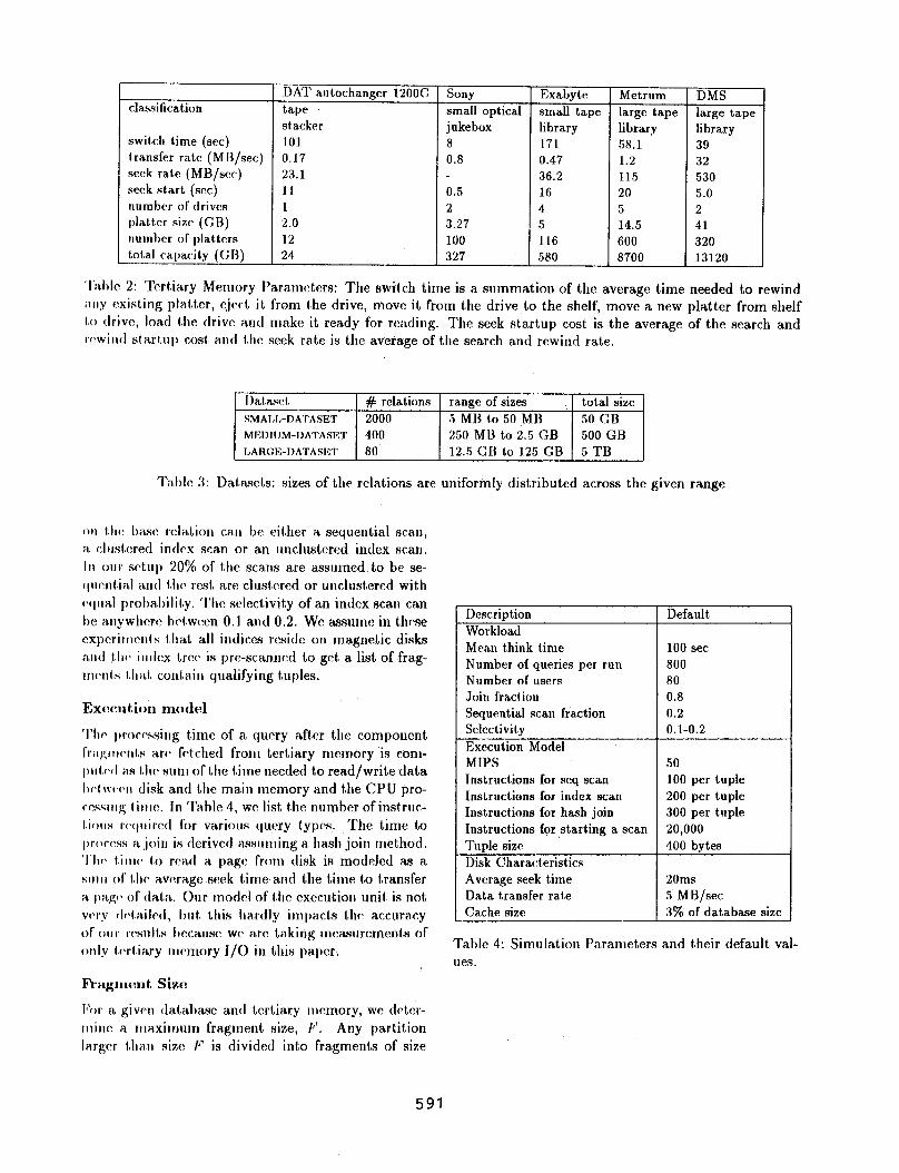
Our simulabor consists of a centralized database sys- tem serving requests from different query streams. We model a closed queuing sysl,em consisting of multiple users who submit a query, wait for the result, and then think for an exponentially distributed time before sub- mitting the next query. Table 2 lists the performance specifications of the four tertiary. memory types we used in our study: (1) the Sony WORM optical juke- box, (2) the Exabyte 8500 tape library, (3) the Metrum RS6000 tape jukebox and (4) Sony’s DMS tape library. These devices were chosen so as to cover adequate rep- resentatives from the diverse tertia.ry memory hard- ware in existence today. Table 3 lists the three datasets that we used as the underlying database. Each dataset is characterized by the range of sizes of the relations and the number of relations. The size of a relation is assumed to be uniformly distributed within the range specified by the dataset. The default size of the cache and the number of users is given in Table 4. Further details about the simulator are given below:
R.elation layout
For laying out the relations on tertiary memory we use the following approach: We divide a relation into par- t,itions of size no more than p. The value of p is always 2 to the pla,tter capncity. These partitions are laid out contiguously on the platters. A partition is stored with equal probability in one of the pa.rtially filled platters that has space for it or a new pla.tter if one is available. We will denote the tota.f number of platters over which da,ta is spread as P. For disk-based platters, the lay- out of da.ta partitions within a. plaiter is not modeled. For tapes, the space between two adjacent pa.rtitions is uniformly dist,ributed between 0 and the total free space left on tape over the number of relations that are assigne< to the tape.’
Workload
Table 4 summarizes the relevant workload parameters and their default values. We simulate a stream of sin- gle relation queries and two-way joins. Base relations for queries are chosen using the 80-20 rule i.e, 80% of the accesses refer to 20% of the relations. The scan
590
classification
switch time (SW) t.ransfer rate (MB/set) seek ra.1.e (MB/src) seek start (WC) num her of drives platkr size- (GR) uumber 0C platters total capac:ity (GR)
DAT autochanger 12OOC tape slacker 101 0.17 23.1 11 1 2.0 12 24
Sony small optical jukebox 8 0.8
0.5 2 3.27 100 327
Exabyte Metrum small tape large tape library library 171 58.1 0.47 1.2 36.2 115 16 20 4 5 5 14.5 116 600 580 8700
DMS large tape library 39 32 I 530 5.0 2 41 320 13120
‘I’al)lc 2: Tertiary Memory Parameters: The swit,ch tirne is a summation of the average time needed to rewind ~I.II.Y nxisl,ing plall~er, ejrct it from the drive, move it from the drive to the shelf, move a new platter from shelf t.o drive, 1oa.d the drive amI make it ready for reading. The seek startup cost is the average of the search and rewind st*art,up cost, a.nd t,he seek rate is the average of the search and rewind rate.
Ihl.a.4 # rehtions range of sizes total size SMAI.I,-DATASET 2000 5 Ml) to 50 MI% 50 GB MEIIN!M-I)ATASET 400 250 MU to 2.5 GB 500 GB
LARGE-IIATASET 80 12.5 GB to 125 GB 5 TB
‘IUlc C!: L)atascts: sizes of the relations are unifortily distributed across the given range
on l.Irr Imsc: relation can he eit,her a sequential sca.ti, ;I cluntcred intlcx aca.n or a.n unclustered index scan. I II our srtup 20% of t,he scans are assumed to be se- ctnf\nt.ial anti t.11~ rest, are clnst~~~~i or uncluatercd with c’ctnal prol&ilily. ‘I‘hc selectivit,y of an index scan can IN anywhcrc bt.wc:cn 0.1 and 0.2. WC a9sumc in thfxae expcrittlmts f.hab all indices reside on magnetic disks and 1.11~ ilitlc:x Irw is pre-scanned to get a list of frag- rrlc~nt~s 1.llil.l contain qualifying tuples.
‘1’11~ tbrorc\ssing time of a. query a,fler the component 1’wg11tvtit.s a.r(’ fc%ched from tertiary memory is com- p11b11 as t.11~ sum of the t,ime needed to read/write data I)VI ww~~ disk and the ma.in memory and the CPU pro- ccssitlg I il,lc. In Ta.hle 4, we list the number of inst.ruc- t.iws rcqnirrd for va.rions query t,ypcs. The time to t)roc(‘ss a. join is derived assnnling a. hash join method. ‘1’11~ t.irtlc> tSo rc\a.d a. page from disk is modeled <as a. $11111 ol’ ~.hr a.vcxrnge seek lime a.nd the time to transfer ii ibiip* of tlatz~ Our model of the execution unil. is n6t vc>ry ~Ir~t.ailf~cl, Init0 this ha.rdly impa.cts the, accuracy of OII~ rcsult,s I~~ause WC arc ta.king measurements of only I.cxri,ia.ry rncm~0r.y J/O in this pil.pCr.
Ia’or a giveu tlntahase and tertiary Illemory, we detar- lninc a tila.xilnum fra.gment size, F’. Any partition Iargc,r t11a11 sixc I’ is divided inbo fra.gments of size
Description Default Workload Mean think time 100 set Number of queries per run 800 Number of users 80 Join fract,ion 0.8 Sequential sca.n fraction 0.2 Selectivity 0.1-0.2
Execution Mode1 MIPS .’ ‘0 Instructions for seq scan 100 per tuple Instructions for index scan 200 per tuple Instructions for huh join 300 per tuple Instructions for starting a scan 20,000
Tuple sisr 400 bytes Disk Charan:t,eristics Average seek time 20ms Data transfer rate 5 .MH/sec Ca.che size 3% of database size
Table 4: Simula.tion Pa.rameters and their default val- ues.
591
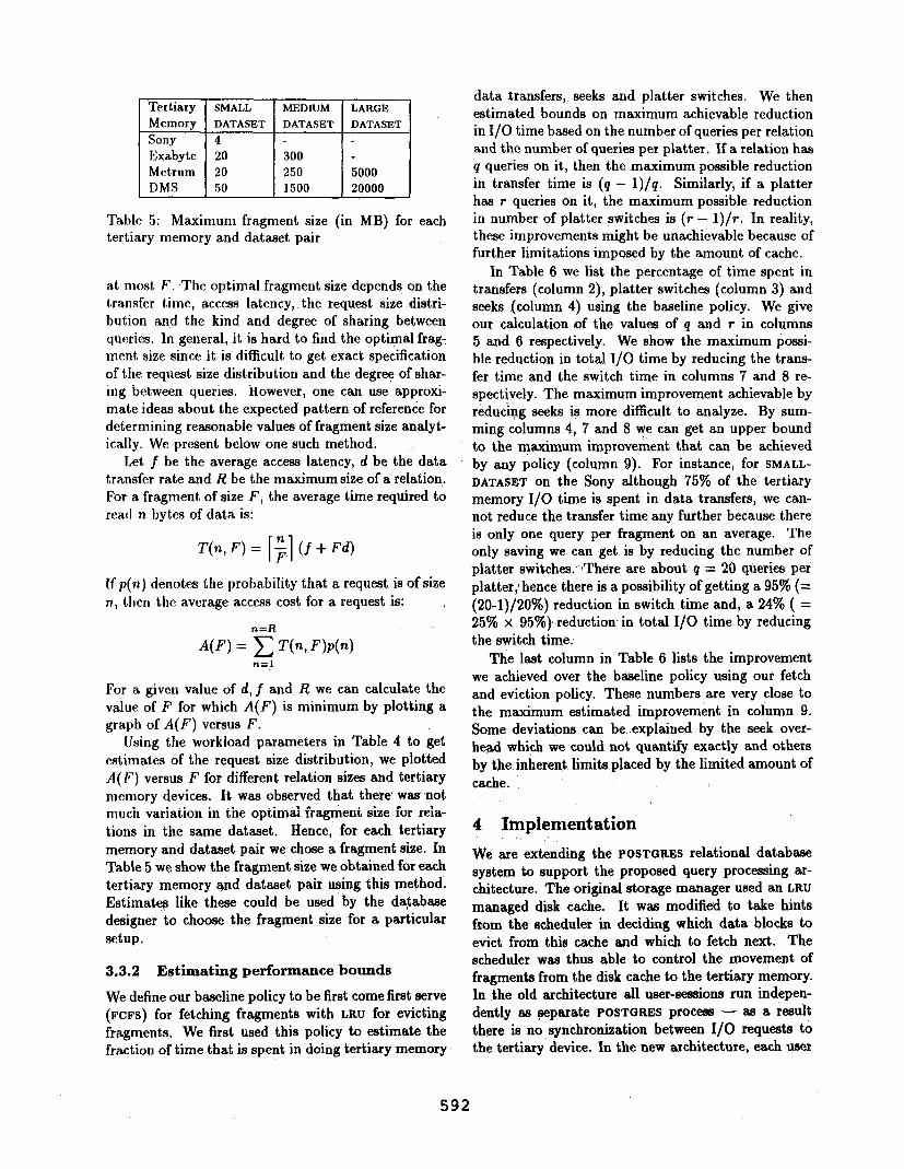
‘htiary SMALL -MEDIUM LARGE
Memory DATASET DATASET DATASET Sony 4
1 DMS SO 1500 20000
Table 5: Maximum fragment size (in MB) for each tertiary memory and dataset pair
at most F. .The optimal fragment size depends on the transfer time, access latency, the request size distri- bution and the kind and degree of sharing between queries. In general, it is hard to find the optimal frag- ment size since it is difficult to get exact specification of the request size distribution and the degree of shar- ing between queries. However, one can use approxi- mate ideas about the expected pattern of referente for determining reasonable values of fragment size analyt- ically. We present below one such method.
Let f be the average access latency, d be the data transfer rate and R be the maximum size of a relation, For a fragment of size F, the average time required to read II bytes of data is:
T(n, F) = [;I (f + Fd)
If p(n) denotes the probability that a request is of size n., then the average access cost for a request is:
n=R
n=l
For a given value of d, f and R we can calculate the value of F for which A(F) is minimum by plotting a graph of A(F) versus F.
Using the workload parameters in Table 4 to get estimates of the request size distribution, we plotted A( I’) versus F for different relation sizes and tertiary memory devices. It was observed that there was not much variation in the optimal fragment size for rela- tions in the same dataaet. Hence, for each tertiary memory and dataset pair we chose a fragment size. In Table 5 we show the fragment size we obtained for each tertiary memory and datsset pair using this method. Estimatq like these could be used by the da;abase designer to choose the fragment size for a particular setup.
3.3.2 Estimating performance bounds
We define our baseline policy to be first come first serve (FCFS) for fetching fragments with LRU for evicting fragments. We first used this policy to estimate the fraction of time that is spent in doing tertiary memory
data transfers, seeks and platter switches. We then estimated bounds on maximum achievable reduction in I/O time based on the number of queries per relation and the number of queries per platter. If a relation has q queries on it, then the maximum possible reduction in transfer time is (q - 1)/q. Similarly, if a platter has r queries on it, the maximum possible reduction in number of platter switches is (r - 1)/r. In reality, these improvements might be unachievable because of further limitations imposed by the amount of cache.
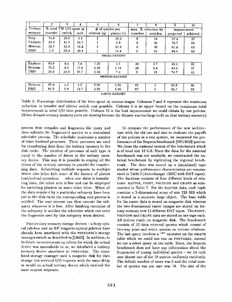
In Table 6 we list the percentage of time spent in transfers (column 2), platter switches (column 3) and seeks (column 4) using the baseline policy. We give our calculation of the values of q and r in columns 5 and 6 respectively. We show the maximum possi- ble reduction in total I/O time by reducing the trans- fer time and the switch time in columns 7 and 8 re- spectively. The maximum improvement achievable by rkdudbg seeks is more difficult to analyze. By sum- ming columns 4, 7 and 8 we can get an upper bound to the maximum improvement that can be achieved by any policy (column 9). For instance, for SMALL- DATASET on the Sony although 75% of the tertiary memory I/O time is spent in data transfers, we can- not reduce the transfer time any further because there is ,only one query per fragment on an average. The only saving we can get is by reducing the number of platter switches.- :Tht?re are about q = 20 queries per platter,‘hence there is a possibility of getting a 95% (= (20-1)/2OY) ‘d t o re UC ion in switch time and, a 24% ( = 25% x 95%) reduction in total I/O time by reducing the switch time:
The last Column in Table 6 lists the improvement we achieved over the baseline policy using our fetch and eviction policy. These numbers are very close to the maximum estimated improvement in column 9. Some deviations can be explained by the seek over- head which we could not quantify exactly and others by the inherent limits placed by the limited amount of cache.
4 Iknpiementation
We are extending the POSTGRES relational database system to support the proposed query processing ar- chitecture. The original storage manager used an LRU managed disk cache. It was modified to take hints from the scheduler in deciding which data blocks to evict from this cache and which to fetch next. The scheduler was thus able to control the movement of fragments from the disk cache to the tertiary memory. In the old architecture all user-sessions run indepen- dently as yparate POSTGRES process - as a result there is no ,synchronization between I/O requests to the tertiary device. In the new architecture, each user
592
1 2 1 3 1 4 5 Tertia.ry % tot,a.l TM I/O spent. in
I 6 7 8 9 10 # of queries per
I ma.x. % reduction by improvement
memory transfer switch seek relation (q) platter (r) transfers switches projected achieved
Sony 71.6 25.0 3.4 1 20.2 0 24 27.4 27
E:xabyte 23.2 42.1 34.7 1 6.8 0 36 70.7 66 Met.rum 16.7 31.9 51.4 1 14.4 0 30 81.4 63
1 I)MS ( 1.9 ( 58.6 1 39.4 1 1 14.4 0 55 94.4 83 SMALL-DATASET
Exabyk! 83.8 8.6 7.6 1.35 1.7 22 3.7 33.3 31 Metrum 75.5 6.9 17.6 1.35 5.18 20 5.6 43.2 37 DMS 30.0 22.3 47.7 1.35 7.2 8 19 74.7 42
MEPIUM-DATASET
Mctrum 97.0 1.1 1.9 5.96 5.96 81 1 83.9 46
I)MS 81.5 5.8 12.7 5.96 5.96 67 5 84.7 59
LARGE-DATASET
‘l’irblc 6: I’ercentagr distribution of the time spent at various stages: Columns 7 and 8 represent the maximum reduction in transfer and platter switch cost possible. Column 9 is an upper bound on the maximum total improvement in tota. I/O time possibJe. Cblumn 10 is the best improvement we could obtain by our policies. (Some data&-tertiary memory pairs ate missing because the dataset was too large to fit on that tertiary memory)
process first compiles and fragments the query, and then submi Is t,he fra.gmant.ed queries to a. centralized sclltdulcr process. The scheduler m&tains a number of slave backeud processes. These processes are used for transferring data from the tertiary memory to the disk cache. Thr number of processes of such type is equal t#o the number of drives in the tertiary mem- ory device. This way it is possible to emplvy all the drives of t,hc tertiary memory in parallel for transfer- ring da.tn. Submitting m~;ltiple requests to multiple tlrivc5 nlso hr4ps hi&: some of t,he latency of plat,ter loit.tl/~~~iloa.tl ol~cra.t.ion --.-- wlion one drive is trarisfcr- ring tla.ta, the robot arm is free and can be employ4 for swit,ching plntters on some other drive. When all iShc da.ta recluind by a. part8icular subqucry ha.ve been p111, in the disk ca.che the corresponding user procrss is notified. ‘I’hc user process can then execute the sub- qnrry whencvm it is free. /\k~ finishing cxccution of t,hc subqucry it, uotifies i,he scheduler which ca.n evict t,he fragment,s used by this subquery when desired.
‘I‘wo tc>rtinry memory st,ora.ge tlevicr:s .- a Sony opti- ~a.1 jukebox and an HP magneto-optical jukebox have a.lrca.dy hcen interfa.ced with t,he POSTGRES'S storage ma.ua.ger switch as described in [Ols92]. In a.ddition, to facilita.tr lucasurements on robots for which the actua.1 device was una.va.ilable to us, we interfackd a. tertiary memory device simula.tor to POSTGRES. The simu- la.ted stora.ge manager used a ma.gnetic disk for da,ta storage but serviced l/O requests wit,11 the sa,me delay as woul(l a,n actual t,ert,ia.ry device which received the same request8 sequence.
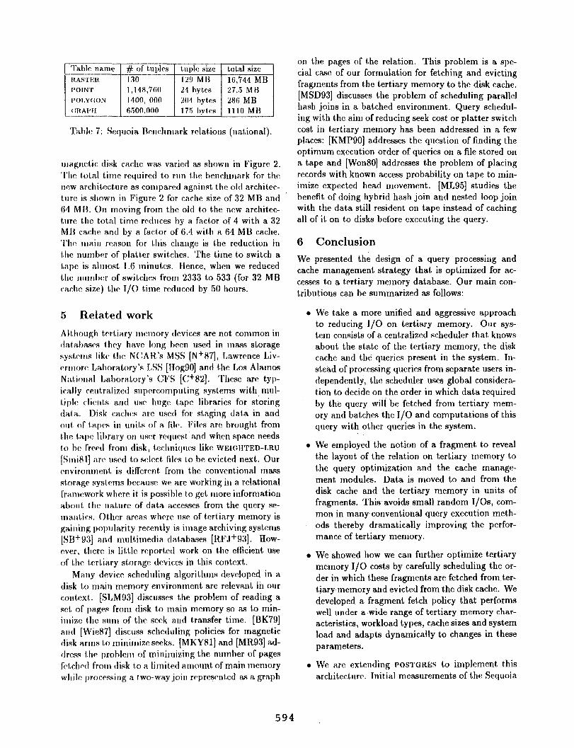
To compare t,he performa.nce of the new architec- ture with the old one and, also to evaluate the pa.yoffs of the policies in a real system, we measured the per- formance of the Sequoia benchmark [SFGM93] queries. We chose the nabional version of the benchmark which is of total size 18 GB. Since the data for the national benchmark was not available, we constructed the na- tional benchmark by replicating the regional bench- mark. The data. was stored on a (simulated) tape stacker whose performance characteristics are summa- rized in Table 2 (Autochanger 1200C with DAT tapes). The da.t,a.base-consists of four different kinds of rela- tions: RASTER, POINT, POLYGON and GRAPH as sum- marized in Table 7. For the RASTER data, each tuple contains a. 2-dimensional array of size 129 MB which is stored as a separate large object. The base table for t,he raster data. is stored on magnetic disk whereas t)he two-dimensional raster images are stored on ter- tiary memory over 12 different, DAT tapes. The POINT,
POLYGON and GRAPH data are stored on one tape each. All indices reside on magnetic disk. The benchmark consists of 10 data retrieval queries which consist of two-way joins and select queries on various relations. The last query involves a “*” operator 011 the GRAPH
table which we could not run on POSTGRES, instead we run a select query on the table. Since, the Sequoia benchmark does not, have any information about the frequencies of posing individual queries - we let each user choose one of the 10 queries uniformly randomly. The default number of users was 5 and the total num- ber of queries ran per user was 10. The size of the
593
~~~
'l'd~lc 7: Sequoia ncnchnla.rk relations (national).
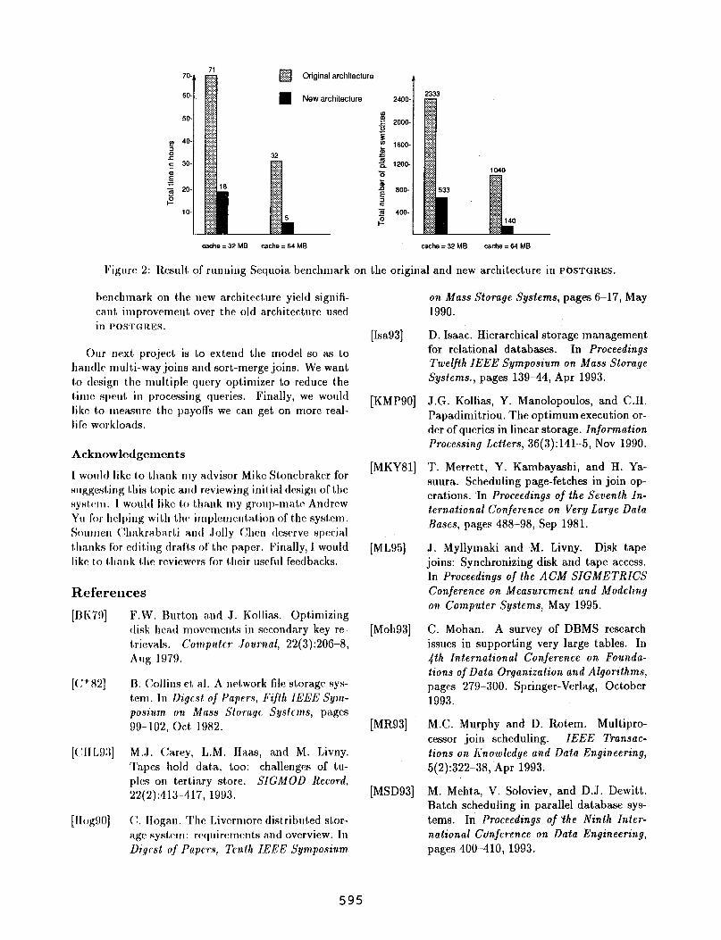
ma.gnctic disk cache was va,ried as shown in Figure 2. ‘UIC I.01,a.l time required to run the benchmark for the new architecture aa compa.red against the old architec- tr~rc: is shown in Figure 2 for ca.che size of 32 MI3 a.nd 64 M R. On moving from the old to the new a,rchitec- ture the total time reduces by a. facCor of 4 with a 32 MH cache a.nd by a. f&or of 6.4 with a 64 MB ca.che. ‘1’11~ Ina.in TCR.SOII for this change is the reduction in 1.11~ number of platter switches. The time to switch a t,a~)e is almost 1.6 minutes. Hence, when we reduced t,he uumbcr of switches from 2333 to 533 (for 32 MB Cil.ClIC size) the I/O time reduced by 50 hours.
5 Related work
Allhough ttrtiilry memory flevices are not common in dil~htJRSf?S they have long I)c~cu used in m;\.ss storage systems like tlw N(:hH.‘s MSS [Nt87], Lawrence Liv- crlnorc I,a.l)ora.tory’s LSS [HogSO] a.nd t,he Los Alamos Nationa. lAora.tory’s CFS [C+82]. ‘l’hcse arc kyJ'-
ically ceutralized suJ)rrcompnling systems with mul- t,iplc cliont,s a.nd usr huge ta.pe libraries for storing tlai,a.. Disk caches a.re. used for st,aging da.ta in a.nd 0111, of tapes in units of a. file. Files are brought from thr tape libra.ry on user request, a.nd when spa.ce needs t,o ho I’rwtl from disk, trclrniqurs like WEMHTED-LRU
[SmiHl] arc‘ used t,o sclcct, files t80 lx evicted next. Our c~nvironmenl, is diflcrent lrom the conventional mass stora.ge S~S~CY~IS hcca.use we are working in a, rela.tional fra,mework where it is possible t,o get more information about, the na.turc of data. ~CCCSSCS from the query sa- malitics. Other area.s where use of tcrt,iary memory is gaining popula.rit,y recently is ima,ge archiving syst,ems [SB+93] and multilnedia. da.ba.bases [ltFJ+93]. TIow- rver, t,hcre is lit,tle reported work on the efficient use of t,lic l.crbia.ry storage devices in this context.
Many device scheduling a.lgorithms developed in a disk to main memory environment arc relevant in our context,. [SI,M93] discusses the problem of reading a set of pages from disk to main memory so as to min- ionize t.he sum of the seek and transfer time. [BK79] a.utl [Wie87] discuss scheduling policies for magnetic disk a.rms t,o minilnize seeks. [MKYHl] and [MR93] ad- dress t.he problem of minimizing the number of pages ft$cl~ctl from disk t,o a. Ii mited a.tnount of main memory while processirlg a l,wo-way join rr:presentcd as a graph
on the pages of the relation. This problem is a spe- cial case of our formulation for fetching and evicting fragments from the tertiary memory to the disk cache. [MSD93] discusses the problem of scheduling parallel hash joins in a batched environment. Query schedul- ing with the aim of reducing seek cost or platter switch cost in tertiary memory has been addressed in a few places: [KMPSO] addresses the question of finding the optimum execution order of queries on a file stored on a tape and [WonSO] addresses the problem of placing records with known access probability on tape to min- imize expected head movement. [ML951 studies the benefit of doing hybrid hash join and nested loop join with the data still resident on tape instead of caching all of it on to disks before executing the query.
6 Conclusion
We presented the design of a query processing and cache management strategy that, is optimized for ac- cesses to a tertiary memory database. Our main con- tributions can be summarized as follows:
We take a. more unified and aggressive approach to reducing J/O on tertiary memory. Our sys- tem consists of a centralized scheduler that knows about the state of the tertiary memory, the disk cache a,nd the queries present in the system. In- stead of processing queries from separate users in- dependently, the scheduler uses global considera- t,ion to decide on the order in which data required by the query wili be fetched from tertiary mem- ory and bat,ches the J/O and computations of this query with other queries in the system.
We employed the notion of a fragment to reveal the layout of the relation on tertiary memory to the query optimization a.nd the cache managc- ment, modules. Data is moved to and from the disk cache and the tertiary memory in units of fragments. This avoids small random I/OS, com- mon in many-conventional query execution meth- ods thereby dramatically improving the perfor- mance of tertiary memory.
We showed how we can further optimize tertiary memory I/O costs by carefully scheduling the or- der in which these fragments are fetched from ter- tiary memory and evicted from the disk cache. We developed a fragment fetch policy that performs well under a wide range of tertiary memory char- act,eristics, workload types, cache sizes and system load and adapts dynamically to changes in these pa.rameters.
We are extending POSTGRES to implement t#his architecture. Initial measurements of the Sequoia
594
7a
6a
50
cache = 32 MB cache = 64 MB
2333
cache = 32 MB cadw=64MB
Figure 2: Result of running Sequoia benchmark on the original and new architecture in P~STGRES.
benchmark on t,he new architecture yield signifi- cn.nt, improvement over the old a,rchitecture used in IWSTGRES.
Our next project is to extend the model so a.s to ha.ndlc mult(i-way joins and sort-merge joins. We want to tlcsign the multiple query optimizer to reduce the tinlc spent in processing queries. Finally, we would like to measure the payofrs we can get on more real- life worklon.ds.
Ackllowlecl~:elllents
1 would like to tha.nk my a.dvisor Mike Stonebra.ker for suggosl,irlg l.his topic and reviewing inil,ial design of the syst,rm. 1 would like to thank my group-ma,tc Andrew YII for helping with the implemcnta.tion of the system. Sounlen (%akra.barti a,ntl Jolly (&XI tlca~rve special t,ha.nks for edit,ing t1radl.s of t,hc: paper. Finally, I would like t,o i,hank the rcviewcrs for lShcir useful feedbacks.
References
[BIi79]
[(:+82]
[( !I1 L93]
[ llog!N~]
F.W. Burton and J. Kollias. Optimizing disk 11ca.d movements in seconda.ry key re- tSricvals. Compukr .Journal, 22(3):206X4, Allff 1979.
B. Collins et n.l. A network file st(oragp sys- tem. lo Dig& of Papers, Fifth IElSE Sym- posi717n on Mass Sforagc Systems, pages 99.-102, act 1982.
M.J. (Carey, L.M. Hans, and M. Livny. Tapes hold data, too: challenges of tu- ples on tertiary store. SJGMOD Record, 22(2):413-417, 19!)3.
(!. IIognn. The Livcrmore dist(rihuted stor- age system: requirements and overview. In
Digest of Papers, ;IEn.th IEEE Synaposium.
[Isa931
[KMPSO]
[MKYU]
[ML951
[Moh93]
[MR93]
[MSD93]
on Mass Storage Systems, pages G-17, May 1990.
D. Isaac. Hierarchical storage management for relational databases. In Proceedings Twelfth IEEE Symposium. on Mass Storage Systems., pages 139~-44, Apr 1993.
J.G. Kollias, Y. Manolopoulos, and C.H. Papadimitriou. The optimum execution or- der of queries in linear storage. Information
Processing Letters, 36(3):141-5, Nov 1990.
‘I’. Merrett, Y. Kambayashi, and H. Ya- suura. Scheduling page-fetches in join op- erations. ‘In Proceedings of the Seventh In- ternational Conference on Very Large Data .Rascs, pages 488-98, Sep 1981.
J. Myllymaki and M. Livny. Disk tape joins: Synchronizing disk and tape access. In Proceedings of the ACM SIGMETRICS Conference on Measurement and Mode1in.g on Computer Systems, May 1995.
C. Mohan. A survey of DBMS research issues in supporting very large tables. In 4th In.ternationa.1 Conference on Founda- tionu of Data Organkation and Algorith.ms, pages 279-300. Springer-Verlag, October 1993.
M.C. Murphy a.nd D. Rotem. Multipro- cessor join scheduling. IEEE Trunsuc- tions on Einowledge and Data Engin,eering, 5(2):322--38;Apr 1993.
M. Mehta, V. Soloviev, and D.J. Dewitt. Batch scheduling in parallel database sys- tems. In Proceedings of ‘th,e Ninth Inter- national Conference on Data Engineering, pages 400.-410, 1993.
595
[N+87] M. Nelson et al. The National Cen- [Won801 C.K. Wong. Minimizing expected head ter for Atmospheric Research Mass Stor- movement in two dimensional and one di- age System. In Digest of Papers, Eighth menaional mass storage systems. ACM IEEE Symposium on Mass Storage Sys- Computing Surveys, 12(2):167-78, Jun terns, pages 12-20, May 1987. 1980.
[Ola92] Michael Allen Olson. Extending the POSTGRES database system to manage tertiary storage. Master’s thesis, Univer- sity of California, Berkeley, 1992.
[RFJ+93] M.F. Riley, .J.J. Feenan Jr., et al. The de- sign of multimediaobject support in DEC Rdb. Digital Technical Journal, 5(2):50- 64, 1993.
[SB+93] T. Stephenson, R. Braudes, et al. Mass storage systems for image management and distribution. In Digest of Papers, Twelfth IEEE Symposium. on Mass Storage Sys- tem.s, pages 233-240, Apr 1993.
[Se1931 P. Selinger. Predictions and challenges for database systems in the year 2000. In Proceedin,gs of the Nineteenth International Conference on Very Large Data Bases, pages 667-675, 1993.
[SFGM93] M. Stonebraker, J. Frew, K. Gardels, and J. Meredith. The sequoia 2000 storage benchmark. SIGMOD Record, 22(2):2--11, 1993.
[SLMSS] B. S g ee er, P. Larson, and R. McFadyen. Reading a set of disk pages. In Proceedings of the Nineteenth International Conference on Very Large Data Bases, pages 592-603, 1993.
[Smi81] A.J. Smith. Long term file migration: de- velopment and evaluation of algorithms. Communications of the ACM, 24(8):521- 32, Aug 1981.
[Son891 Sony Corporation, Japan. Writable Disk Drive WDD-600 and Writable Disk WDM- 6DL0 Operating Instructions, 1989. 3-751- 047-21(1).
[St0911 M. StonebTaker. Managing persistent ob- jects in a multi-level store. SIGMOD Record, 20(2):2-11, 1991.
[Wie87] G. Wiederhold. File organization for database design. McGraw-Hill, New York, 1987.
596