query based uml modeling - umd israustin/ense623.d/projects06.d/dennymathewproje… · this project...
TRANSCRIPT

1
Query Based UML Modeling
Validation and Verification of the System Model and Behavior for a Hydraulic Crane
Denny Mathew
ENPM 643System Validation and VerificationInstructor: Dr. Mark AustinFall 2006
2
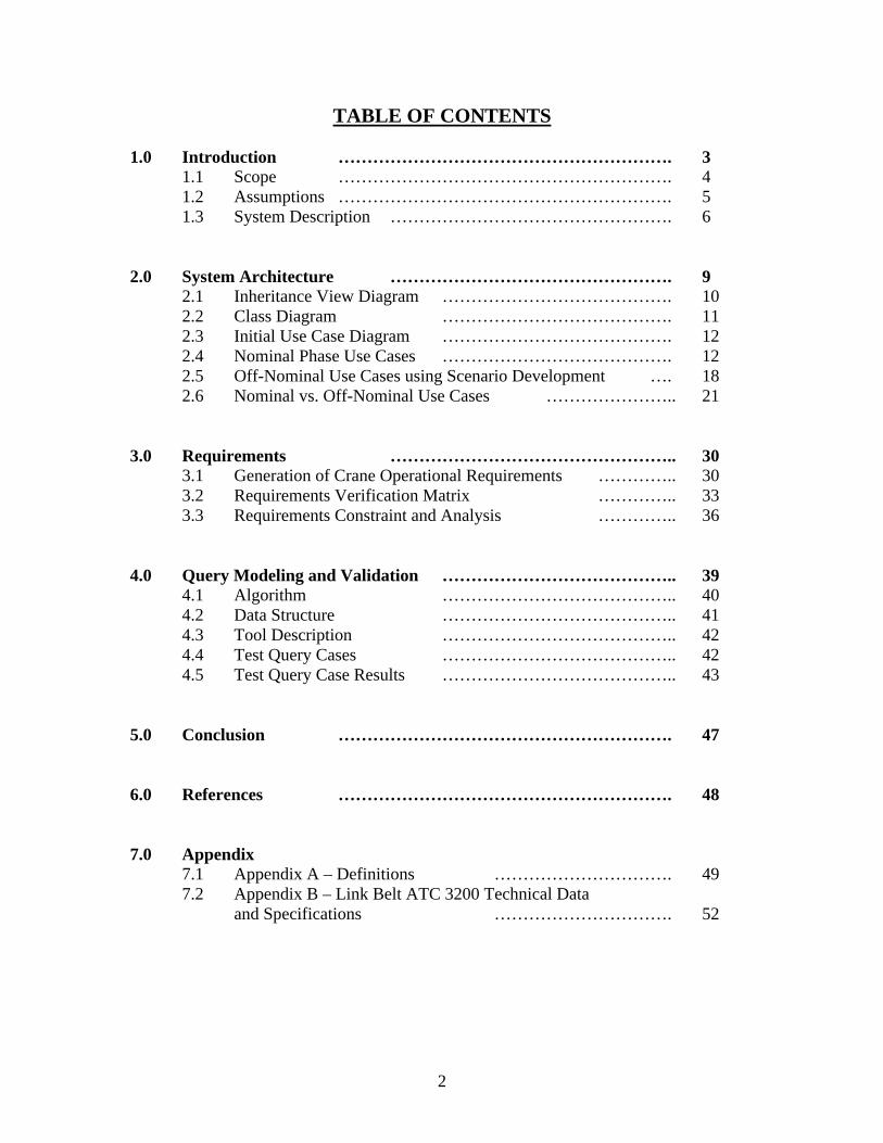
TABLE OF CONTENTS
1.0 Introduction …………………………………………………. 31.1 Scope …………………………………………………. 41.2 Assumptions …………………………………………………. 51.3 System Description …………………………………………. 6
2.0 System Architecture …………………………………………. 92.1 Inheritance View Diagram …………………………………. 102.2 Class Diagram …………………………………. 112.3 Initial Use Case Diagram …………………………………. 122.4 Nominal Phase Use Cases …………………………………. 122.5 Off-Nominal Use Cases using Scenario Development …. 182.6 Nominal vs. Off-Nominal Use Cases ………………….. 21
3.0 Requirements ………………………………………….. 303.1 Generation of Crane Operational Requirements ………….. 303.2 Requirements Verification Matrix ………….. 333.3 Requirements Constraint and Analysis ………….. 36
4.0 Query Modeling and Validation ………………………………….. 394.1 Algorithm ………………………………….. 404.2 Data Structure ………………………………….. 414.3 Tool Description ………………………………….. 424.4 Test Query Cases ………………………………….. 424.5 Test Query Case Results ………………………………….. 43
5.0 Conclusion …………………………………………………. 47
6.0 References …………………………………………………. 48
7.0 Appendix7.1 Appendix A – Definitions …………………………. 497.2 Appendix B – Link Belt ATC 3200 Technical Data
and Specifications …………………………. 52

3
1.0 Introduction
This project report is a detailed case study on the development and use of a query based UML modeling tool. Throughout the last decade, UML along with its derivative, SysML have been used throughout the software and engineering communities to model system level architectures for various systems and subsystems. UML/SysML was designed to provide simple but powerful constructs for modeling a wide range of systems engineering problems. It is particularly effective in specifying requirements, structure, behavior, and allocations, and constraints on system properties to support engineering analysis. The language is intended to support multiple processes and methods such as structured, object-oriented, and others, but each methodology may impose additional constraints on how a construct or diagram kind may be used.
As flexible as UML/SysML may be, one of its drawbacks is that it is not very useful in an interactive dynamic format. Once a UML model is created, it is essentially a static system model that is little more than a “pretty picture”. It would be greatly beneficial if it could be queried, and dynamically linked. Querying would enable an engineer to see how a particular element in a UML model is linked to another element, and also how changing one would alter the overall model. Currently this capability is lacking. Although relatively intuitive on small systems, the ability to query and dynamically link various UML models is of huge consequence on large and complex projects. This case study looks at a software algorithm model, the UML Query and Link Analysis Tool (UQLAT), for querying and dynamically linking UML models. Much of this work is done by me as part of an Independent Research and Development (IRAD) effort for my company, Raytheon. As a result of this, I am not allowed to disclose the actual algorithm or screenshots of the querying tool. However, this case study will discuss the data structure, general algorithm logic, and results of sample queries and dynamic links for a particular system.
For this case study, in addition to the UQLAT, a full Verification and Validation analysis was conducted on a hydraulic crane. The case study includes a full system architecturedevelopment, including use cases, scenario development, requirements generation, verification of the system, and finally validation using the UQLAT.

4
1.1 Scope
This case study focuses on the operational sequencing of an all-terrain hydraulic crane, using positive (nominal) and negative (off-nominal) use cases to model overall system behavior. The systems architecture describes crane operation across five distinct phases:
Pre-Start Initiation Handling and Attaching the Load Lifting the Load Maneuvering the Load Ending Lift
These five phases describe the entire operational lifecycle of a stationary crane. This case study has chosen the route of using nominal and off-nominal use cases to describeoverall system architecture1. Nominal and off-nominal use cases are described using activity diagrams in the Higraph style. Nominal use cases describe the crane system as it is intended to operate during a particular phase, whereas the off-nominal use casesdescribe how a nominal operation can be negatively affected, leading to either serious injury or fatality. To arrive at the off-nominal use cases, a separate failure analysis was conducted. The outcome of this failure analysis was the development of off-nominal use cases. There can theoretically be hundreds of off-nominal use cases. However to keep this case study manageable, only the most pertinent off-nominal use cases were included. Each nominal use case was matched up to no more than 3 off-nominal use cases for brevity.
Finally, only the nominal and off-nominal use cases presented in this case study are analyzed using UQLAT.
1 Reference 2

5
1.2 Assumptions
The analysis conducted for this report considers the hydraulic all-terrain mobile crane system commonly used at various construction sites. The analysis is kept at a general level without reference to a particular model.
Furthermore, the following conditions were used to bind and constrain the analysis of the crane system for this report:
- Crane Type: Only all-terrain mobile cranes are considered for this report. Crawlers, tower-cranes, floating platform cranes, derricks, lattice-structure cranes and truck-based “non-outrigger” cranes are not covered by the analysis in this report.
- Risk: Only safety-related risks are evaluated and analyzed for the failure analysis when developing off-nominal use cases. Safety related risks are injury and fatality. Mission assurance risk, financial risk, and any other non-safety risks are not evaluated in this report.
- Operation: Only stationary crane operations are considered for this report. There are additional crane safety requirements and conditions that exist for cranes when in motion. However these requirements are beyond the scope of this report.
- Analysis Extent: The level of analysis for this case study is constrained at the operational level. In other words, only the operational system architecture is studied here. The various lower level mechanical, software, and electrical functions are not discussed, unless there is a direct bearing on the operational phases.

6
1.3 System Description
Hydraulic cranes are very simple by design but can perform monumental tasks that would otherwise seem impossible. In a matter of minutes, these machines can raise multi-ton bridge beams on highways, heavy equipment in factories and even lift beachfront houses onto pilings. The hydraulic crane is based on a simple concept -- the transmission of forces from point to point through a fluid. Most hydraulic machines use some sort of incompressible fluid, a fluid that is at its maximum density. Oil is the most commonly used incompressible fluid for hydraulic machines, including hydraulic cranes. In a simple hydraulic system, when a piston pushes down on the oil, the oil transmits all of the original force to another piston, which is driven up.
A hydraulic pump creates the pressure that moves the pistons. Pressure in a hydraulic system is created by one of two types of hydraulic pumps: the variable-displacement pump, and the gear pump. Most hydraulic truck cranes use two-gear pumps that have a pair of inter-meshing gears to pressurize the hydraulic oil. When pressure needs to increase, the operator pushes the foot throttle to run the pump faster. In a gear pump, the only way to get high pressure is to run the engine at full power.
For this case study, a representative hydraulic crane model was chosen for comparative analysis. The model chosen was the 200 ton-capacity Link-Belt ATC 3200 hydraulic truck crane2. This crane uses a 388 in3 diesel engine that generates up to 184 horsepower. The engine is connected to three two-gear pumps, including:
Main pump - This pump operates the piston rod that raises and lowers the boom, as well as the hydraulic telescoping sections that extend the boom. The main pump is able to generate 170.7 gpm of pressure. It generates more pressure than the other two pumps because it is responsible for moving much more weight.
Pilot pressure counterweight pump - A hydraulic truck crane uses counterweights on the back of the cab to keep it from tipping over. These are added and removed by a hydraulic lift that has its own pump. The counterweight gear pump can generate 1,400 psi.
Steering/outrigger pump - One pump controls the steering and the outriggers. The outriggers are used to stabilize the truck during lifting operations. Because steering and outrigger operation are not performed simultaneously, they run off of the same pump. This pump generates 1,600 psi.
Some basic parts of a hydraulic truck crane include:
Boom - The large arm mainly responsible for lifting Counterweights - Multi-ton weights placed on the back of the cab to prevent the
crane from tipping during lifts Jib - Lattice structure that extends out of the boom Outriggers - Supports that keep the crane balanced Rotex gear - Large gear under the cab that allows the boom to be rotated
2 Appendix B

7
Boom Level Indicator - Array of lights located in the cab just above the operator's eye level; flashes if crane's lifting limits are reached
Reinforced-steel cable Hook Clutch Joystick
The most recognizable part of any crane is the boom. This is the steel arm of the crane that holds the load. Rising up from just behind the operator's cab, the boom is the essential piece of a crane, allowing the machine to raise loads to heights of several dozen feet.
Reinforced-steel cable lines run from a winch just behind the operator's cab, extending up and over the boom and jib. The lines run up the boom and jib and attach to a metal ball that keeps the lines pulled taut when no load is attached to the hook.
To maneuver the load, the boom has to be able to move right and left, as well as up and down. Underneath the operator's cab is a Rotex gear on a turntable bearing that turns at 1.5 revolutions per minute (rpm). It is driven by a bidirectional, hydraulic motor mounted on the cab and housed in a metal cover to prevent injuries. The rotation is controlled by a foot-operated, hydraulic pedal in the cab.
Hydraulic truck cranes are used to lift heavy loads to tall heights, and it's important that the truck be completely stable during the lifting operation. The tires don't offer the necessary stability needed, so the truck employs outriggers that act as balances to keep the crane from leaning too much to one side or the other. The outriggers use hydraulics to lift the entire truck, tires and all, off the ground. The outriggers are comprised of the beam, which is the leg of the outrigger, and the pad, which is the foot. Sometimes, "floats" or “load distribution blocks” are placed under the pad to dissipate the force of the crane and the load over concrete or pavement. Floats are usually wood planks that are lined up to create a base that is larger than the pad itself.
The Link-Belt ATC 3200 hydraulic truck crane has two basic types of controls for maneuvering a load:
Joysticks - There are two joysticks in the cab. One controls left-to-right movement of the boom, and the other controls forward and aft movement.
Foot pedals - These pedals are responsible for retracting and extending the telescoping sections of the boom. They also control the amount of pressure being generated by the pump.
Joy sticks and foot pedals are connected to hydraulic hoses that connect various hydraulic rams to spool valves. The spool valve is connected to the hydraulic pump via a third hose that is placed between the two hoses that run from the spool valve to the hydraulic ram. When a joystick is pushed in one direction, it causes the valve to shut off one of the

8
hydraulic hoses leading to the ram and open the other. Which way the joystick is pushed determines whether the piston in the hydraulic ram slides inward or out.
Prior to any lift, the operator enters data into a computer known as the boom level indicator located inside the cab, including the weight of the object to be lifted and the height to which it is to be lifted. This computer serves as the operator's backup, warning the operator if the crane is being pushed beyond its capability. Using a binder of load rating charts in the cab, the operator also determines the angle of lift and the radius of the boom. Once all of this is entered, the computer can track the progress of the lift and warn the driver if the crane is nearing its limitations. If the boom is lifted too high for the load amount, a series of lights and audible alerts just above the inside of the front window will begin to light up.
There are at least two other people needed to perform a lift properly, including the oilerand the signalman. These two people along with any other construction crew involved with the construction process comprise the “ground personnel”. The oiler is responsible for making sure that all of the crane's parts are in place and secured prior to any lift. He or she also acts as a spotter during a lift to ensure that the lift is being performed properly. The signalman, as the name suggests, gives hand signals to the operator during the lift to make sure the load is being maneuvered correctly.

9
2.0 System Architecture
The operational sequence of a crane consists of five distinct phases that are conducted in order. Each of these five phases, in turn have many steps and actions that need to be completed. The proper sequencing of actions are:
1. Phase 1 Initiate pre-start inspection: these are a set of instructions and checklists that a crane operator must ensure are in place before turning on the engine
2. Phase 2 Handle and attach the load: this phase includes the placement and positioning of the load onto the crane hook
3. Phase 3 Lift the load: this phase is the actual raising of the crane boom with the load fully attached (vertical movement)
4. Phase 4 Maneuver the load: this phase is when the load is cleared for horizontal movement, and any subsequent vertical movements
5. Phase 5 End lifting: this phase includes the lowering of a load, and all post landing operations
Fig. 1 Crane Operational Phase
Initiate Pre-Start Inspection
Handle & Attach the Load
Lift the Load Maneuver the Load
End Lifting
Phase 1 Phase 2 Phase 3 Phase 4 Phase 5

10
2.1 Inheritance View Diagram
The inheritance view shows a detailed view of the attributes and functions of the crane system. The attributes and functions are split between the main system and the subsystem of the crane.
Fig. 2 Inheritance View Diagram

11
2.2 Class Diagram
The class diagram depicts the overall structural breakdown of the crane along with its subsystems. Each subsystem is shown with its major function.
CRANE
Boom
Lift ( )
Counterweight
Tipping ( ) Support ( )
Rotex Gear
Rotation ( )
Boom Level Indicator
Load Limit ( )
Clutch
Brake ( )
Joystick
Position ( )Balance ( )
Reinforced Steel Cable
Lift ( )
Jib
Support ( )
Hook
Attach ( )Lift ( )
Outrigger
Balance ( )Support ( )
Fig.3 Crane Class Diagram

12
2.3 Initial Use Case Diagram
Fig.4 Initial Use Case
2.4 Nominal Phase Use Cases
This section describes the nominal use cases for the five operational phases of the crane. Activity diagrams using the Higraph notation is employed to show the time sequence and order of the various functions and actions within each phase. The Activity diagrams describe how a particular phase is supposed to properly execute its operations. The rectangular boxes are action elements, whereas the rounded boxes are state elements. Action elements represent events that require user input (ex. pressing a button or typing in a number). State elements represent events that are an outcome of a particular Action element. State elements represent conditions, and do not need to be acted upon.
CRANE
ACTOR
Crane Operator
Signalman
Oilman
Initiate Pre-Start Inspection
Handle and Attach the Load
Lift the Load
Maneuver the Load
End Lifting

13
Use Case 1 - Phase 1: Initiate Pre-Start InspectionDescription: The crane operator goes through a pre-start checklist for safetyPrimary Actor: Crane OperatorPre-Conditions: Crane Operator has access to the crane
Fig. 5 Phase 1 Activity Diagram

14
Use Case 2 - Phase 2: Handle and Attach the LoadDescription: Load is measured, calibrated and put onto the crane hookPrimary Actor: Crane Operator, OilmanPre-Conditions: Pre-Inspection checklist was conducted
Fig 6 Phase 2 Activity Diagram.

15
Use Case 3 – Phase 3: Lift the LoadDescription: Crane lifts the load after it has been attachedPrimary Actor: Crane OperatorPre-Conditions: Pre-Inspection checklist was conducted,
The load has been handled and attached
Fig.7 Phase 3 Activity Diagram

16
Use Case 4 - Phase 4: Maneuver the LoadDescription: Crane moves the load to the desired positionPrimary Actor: Crane Operator, SignalmanPre-Conditions: Pre-Inspection checklist was conducted,
The load has been handled and attachedThe load has been lifted successfully
Fig.8 Phase 4 Activity Diagram

17
Use Case 5 - Phase 5: End LiftingDescription: Crane lands the load, and lifting is brought to an end. Primary Actor: Crane Operator, OilmanPre-Conditions: Pre-Inspection checklist was conducted,
The load has been handled and attachedThe load has been lifted successfullyThe load has been maneuvered successfully
Fig.9 Phase 5 Activity Diagram

18
2.5 Off-Nominal Use Cases using Scenario Development
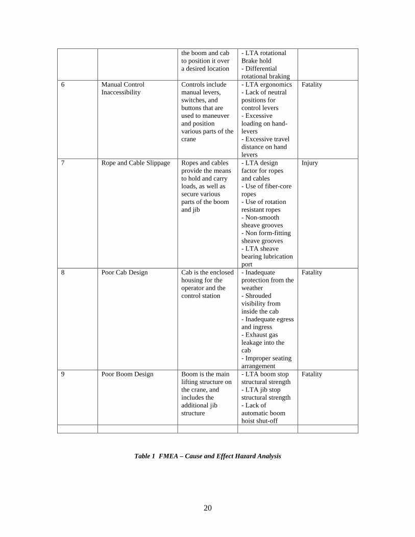
Off-Nominal use cases were developed for the five crane operational phases. The nominal use cases described in section 2.4 depict the sequence of events that are expected to occur during the normal execution of a particular phase. It does not factor in unexpected events, failure events, and other disturbances. However, these events are important in understanding how a system fails, and consequently lead to fatalities. Off-Nominal use cases can be developed using Failure Mode and Error Analysis (FMEA) techniques, and in particular Cause and Effect Hazard Analysis (CEHA). Furthermore, this design project extends the idea presented by Uchitel, Kramer, and Magee in using behavior models by using implied scenarios, as well as correlating positive and negative use cases3. CEHA analysis involves the identification of all possible initiating and contributory hazards that lead to an adverse event flow leading to harm. For this project, a separate CEHA analysis was conducted to identify the major failure points and events, as well as their criticality and consequence levels. These were then combined to form negative or off-nominal use cases in the form of implied scenarios. That work is beyond the scope of this report, but the end results of the CEHA is summarized in Table 1. For each nominal use case, there can be tens of hundreds of off-nominal use cases. However, to keep this project manageable, only the most pertinent off-nominal use cases are discussed for each phase. Finally, each nominal use case is matched up to its corresponding off-nominal use case, by analyzing which off-nominal and nominal use cases have the strongest cause and effect relationship. Some nominal use cases only have one off-nominal use case, while others have many. Some off-nominal use cases are also repeated by other nominal use cases.
It is important to realize that the off-nominal use cases presented in this report are just few of the possible scenarios that exist for each nominal use case. It is by no means an exhaustive list. It should be evident that nominal use cases represent the way a system is intended and expected to work ( a positive), whereas the off-nominal use cases depict the undesired flow of events (a negative). As described by Uchitel, Kramer, and Magee 4, the use of positive and negative implied scenarios are extremely beneficial in discovering system weakness and pitfalls when designing a system, that may not be as easily discovered by simply using UML/SysML or other modeling tools. This in turn, helps one design a more robust and error proof nominal system architecture.
3 Reference 24 Reference 2

19
Failure # Primary Hazard Definition Contributor Consequence1 Poor Startup Crane’s inability to
startup in accordance with established safety procedures
- LTA Training- LTA Physical and Mental Coordination- LTA Procedural Checklist
Injury
2 Forward and backward Instability
Crane’s ability to resist overturning in the direction opposite the boom point while in the unloaded condition
- Crane not designed with shortest allowable boom- Insufficient outrigger structural integrity- Imbalanced weight distribution on all wheels- Excessive design margin between center of gravity and the axis of rotation
Fatality
3 Boom Hoist Mechanism Instability
Boom hoist mechanism supports the boom and controls the boom angle
- Insufficient rope capacity in the boom hoist drum to cover all positions- Insufficient rope strength in the boom hoist drum - LTA braking mechanism to prevent accidental boom lowering- Failure of load-hold check valve
Fatality
4 Load Hoist Mechanism Instability
Load hoist mechanism is a hoist drum and reeving system used for lifting and lowering loads
- Load hoist drums with LTA power- Insufficient thermal rating for load hoist drum brake and clutch- Insufficient rope strength in load hoist drums- Lack of anti-drum rotation controller- Lack of anti-drum rotation hold-check valve mechanism- Improper foot rest
Fatality
5 Swing Mechanism Instability
The swing mechanism rotates
- Lack of boom support
Fatality
20
the boom and cab to position it over a desired location
- LTA rotational Brake hold- Differential rotational braking
6 Manual Control Inaccessibility
Controls include manual levers, switches, and buttons that are used to maneuver and position various parts of the crane
- LTA ergonomics- Lack of neutral positions for control levers- Excessive loading on hand-levers- Excessive travel distance on hand levers
Fatality
7 Rope and Cable Slippage Ropes and cables provide the means to hold and carry loads, as well as secure various parts of the boom and jib
- LTA design factor for ropes and cables- Use of fiber-core ropes- Use of rotation resistant ropes- Non-smooth sheave grooves- Non form-fitting sheave grooves- LTA sheave bearing lubrication port
Injury
8 Poor Cab Design Cab is the enclosed housing for the operator and the control station
- Inadequate protection from the weather- Shrouded visibility from inside the cab- Inadequate egress and ingress- Exhaust gas leakage into the cab- Improper seating arrangement
Fatality
9 Poor Boom Design Boom is the main lifting structure on the crane, and includes the additional jib structure
- LTA boom stop structural strength- LTA jib stop structural strength- Lack of automatic boom hoist shut-off
Fatality
Table 1 FMEA – Cause and Effect Hazard Analysis
21
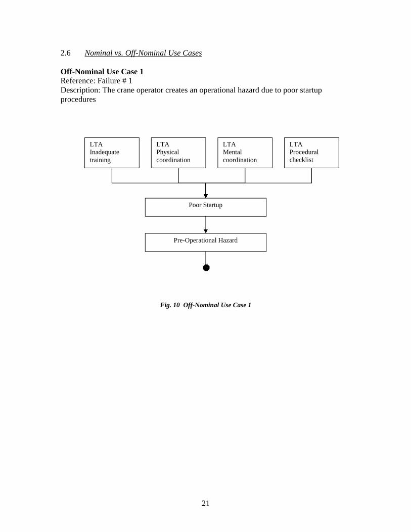
2.6 Nominal vs. Off-Nominal Use Cases
Off-Nominal Use Case 1Reference: Failure # 1Description: The crane operator creates an operational hazard due to poor startup procedures
Fig. 10 Off-Nominal Use Case 1
LTAPhysical coordination
LTAMental coordination
LTA Procedural checklist
Poor Startup
Pre-Operational Hazard
LTA Inadequate training
22
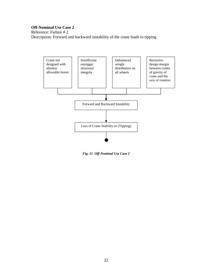
Off-Nominal Use Case 2 Reference: Failure # 2Description: Forward and backward instability of the crane leads to tipping
Fig. 11 Off-Nominal Use Case 2
Insufficient outrigger structural integrity
Imbalanced weight distribution on all wheels
Recessive design margin between center of gravity of crane and the axis of rotation
Forward and Backward Instability
Loss of Crane Stability or (Tipping)
Crane not designed with shortest allowable boom

23
Off-Nominal Use Case 3Reference: Failure # 3Description: Poor boom and rope conditions lead to loss of boom hoist stability
Fig. 12 Off-Nominal Use Case 3
Insufficient rope strength in the boom hoist drum
Less than adequate (LTA) braking mechanism to prevent accidental boom lowering
Failure of load-hold check valve
Boom Hoist Mechanism Instability
Loss of Boom Hoist Mechanism Stability
Insufficient rope capacity in the boom hoist drum to cover all positions

24
Off-Nominal Use Case 4Reference: Failure # 4Description: Poor drum and rope conditions lead to loss of load hoist stability
Fig. 13 Off-Nominal Use Case 4
Insufficient thermal rating for load hoist drum brake and clutch
LTA rope strength in load hoist drums
Poor foot rest
Load Hoist Mechanism Instability
Loss of Load Hoist Mechanism Stability
Load hoist drums with LTA power
Lack of anti-drum rotation hold-check valve mechanism
Lack of anti-drum rotation controller

25
Off-Nominal Use Case 5Reference: Failure # 5Description: Poor brake hold and boom support lead to erratic swinging
Fig. 14 Off-Nominal Use Case 5
Lack of boom support
LTA rotational brake hold
Differential rotational braking
Swing Mechanism Instability
Erratic Swinging

26
Off-Nominal Use Case 6Reference: Failure # 6Description: Poor ergonomics lead to positional errors
Fig. 15 Off-Nominal Use Case 6
Lack of neutral position for control levers
Excessive loading on hand-levers
Excessive travel distance on hand-levers
Manual Control Inaccessibility
Inability to Hold Position
LTA ergonomics

27
Off-Nominal Use Case 7Reference: Failure # 7Description: Poor rope and cable strength leads to premature lifting and landing
Fig. 16 Off-Nominal Use Case 7
Use of fiber-core ropes
Use of rotation resistant ropes
LTA sheave bearing lubrication port
Rope and Cable Slippage
Premature Lifting and Landing of Loads
LTA design factor for ropes and cables
Non-form fitting sheave grooves
Non-smooth sheave grooves

28
Off-Nominal Use Case 8Reference: Failure # 8Description: Poor ergonomic and cab design issues lead to operator errors
Fig. 17 Off-Nominal Use Case 8
Shrouded visibility from inside the cab
Inadequate egress and ingress
Poor Cab Design
Degradation of Operator Coordination
Inadequate Protection from the weather
Improper seating arrangement
Exhaust gas leakage into the cab

29
Off-Nominal Use Case 9Reference: Failure # 9Description: Poor boom design leads to boom overturning
Fig. 18 Off-Nominal Use Case 9
Allocation of Nominal to Off-Nominal Use Cases:
Phase (Nominal) Failure (Off-Nominal)1: Initiate Pre-Start Inspection 12: Handle and Attach the Load 2, 93: Lift the Load 3, 4, 6, 8, 94: Maneuver the Load 3, 5, 6, 7, 8, 95: End Lifting 4, 6, 8
Table 2 Use Case Allocation
LTA boom stop structural strength
LTA jib stop structural strength
Lack of automatic boom hoist shut-off
Poor Boom Design
Overturning of the Boom

30
3.0 Requirements
The requirements generated for this report are done by extensive research of hydraulic cranes. These operational and design requirements are gathered by researching various crane manufacturing operational specifications, and design specifications. The requirements presented here are pertinent and applicable to the five operational phases of a crane. Verification and Validation of these requirements, however, require that a specific hydraulic crane model be chosen. For the purposes of this report, the Link-Belt ATC 3200 hydraulic truck crane was chosen. Operational and Design specifications were obtained from the manufacturer 5, and a full requirement verification and validation was conducted for this particular crane model.
3.1 Generation of Crane Operational Requirements
Req. # Main Requirement Derived Requirement1 To protect against tipping due to excessive
moment loading1.1 Utilize only cranes with appropriately designed booms
2 To protect against accidental lowering of boom 2.1 Install new braking system2.2 Test load-hold valve2.3 Install load-hold valve2.4 Test complete braking hydraulic system2.5 Test braking and valve at the extremes of load and range
3 To prevent backward crane tipping 3.1 Adequate boom structural design3.2 Install jib stop mechanism3.3 Install boom hoist shutoff mechanism
4 To prevent buckling of outriggers 4.1 Reinforce weak outriggers with tension cables
5 To prevent crane tilt 5.1 Test crane unloaded before utilizing it with loads on level surface5.2 Change wheels and tires5.3 Check suspension system
6 To prevent rope damage 6.1 Ensure enough rope length to support all maximum boomextensions
7 To prevent accidental load crashing 7.1 Install adequate power supply for drum7.2 Install new rope7.3 Install properly thermal rated brakes and clutch7.4 Ensure adequate ergonomics (foot rest, seating, etc…)7.5 Install new anti-drum rotation controller7.6 Install anti-drum rotation mechanism
8 To prevent non-smooth rotation of turntable 8.1 Install rotational brake hold that prevents accidental and differential braking related movements
9 To permit reliable and smooth physical coordination of the operator in conducting crane operations.
9.1 Install or modify cab area for each operator9.2 Ensure engine exhaust is prevented from entering the cab
10 To ensure Operator and Ground Personnel can communicate
10.1 Ensure there is a built-in communication channel between the Crane Operator and Ground Personnel
5 Reference 5

31
11 To ensure boom structural integrity is maintained
11.1 Protect boom against environmental degradation11.2 Ensure monthly inspections on boom structural integrity11.3 Ensure proper boom coating to protect against corrosion11.4 Use cranes designed for the proper weather conditions
12 To ensure boom structural integrity is maintained
12.1 Protect against loose boom bolts and rivets
13 To prevent crane tipping 13.1 Check for counterweight attachment connections13.2 Check for structural (i.e. cracks) within the counterweights
14 To prevent rope/cable slippage 14.1 Inspect drum/sheave weekly to ensure smoothness14.2 Use proper drum lubrication to ensure minimum damage from nominal rope/cable shear stress
15 To prevent load slippage from hook 15.1 Ensure proper monthly maintenance and inspection of hook assembly15.2 Do not use loads greater than the hook rating15.3 Avoid harsh impact landing of hook and load hoist assembly
16 To give operator knowledge of crane capabilities and limitations
16.1 Ensure load rating charts are always present before any operation
16.2 Ensure periodic inspections check for updated and clearly legible load rating charts
17 To prevent erratic spin of the turntable 17.1 Ensure turntable guard is in place17.2 Inspect turntable gear mechanisms weekly for wear
18 To ensure smooth movement of boom, jib, and load
18.1 Conduct monthly inspection of all levers and joysticks, including travel and response adjustments18.2 Proper lubrication of connecting parts
19 To protect moving parts against environmental damage
19.1 Ensure guards to protect moving parts are in place before crane operation19.2 Conduct weekly inspections to determine condition of guard19.3 Conduct weekly inspections to determine firm placement of guard (including the bolts and rivets holding it in place)
20 To protect connecting parts (pins, bearings, rods, rivets) against environmental damage
20.1 Conduct weekly inspections to assess connecting part condition20.2 Ensure guard is in place to protect connecting parts
21 To protect crane from tipping during heavy lifting
21.1 Inspect tire condition before every operational cycle21.2 Maintain proper air pressure in the tires
22 To prevent loss of hydraulic pressure due to ruptured hose
22.1 Conduct weekly Inspections for hydraulic hose leakage22.2 Replacement of hoses that exceed minimum threshold thickness22.3 Proper placement of hoses to avoid scrubbing from other mechanical parts22.4 Ensure guard is in place
23 To prevent loss of hydraulic pressure due to hydraulic pump failure
23.1 Monthly Inspections for hydraulic pump pressure23.2 Ensure all leakages are fixed prior to operation23.3 Minimize vibration by using appropriately rated dampeners23.4 Ensure pump casing is not dented and is free from ruptures prior to operation

32
24 To prevent loss of hydraulic pressure due to hydraulic cylinder damage
24.1 Monthly Inspections for hydraulic pump pressure24.2 Ensure all leakages are fixed prior to operation24.3 Minimize vibration by using appropriately rated dampeners24.4 Ensure pump casing is not dented and is free from ruptures prior to operation
25 To prevent loss of hydraulic pressure due to broken hydraulic filter
25.1 Weekly to monthly replacement of hydraulic filter, as needed, depending on operation cycles25.2 Ensure properly recommended filter is used
Table 3 Crane Operational Requirements

33
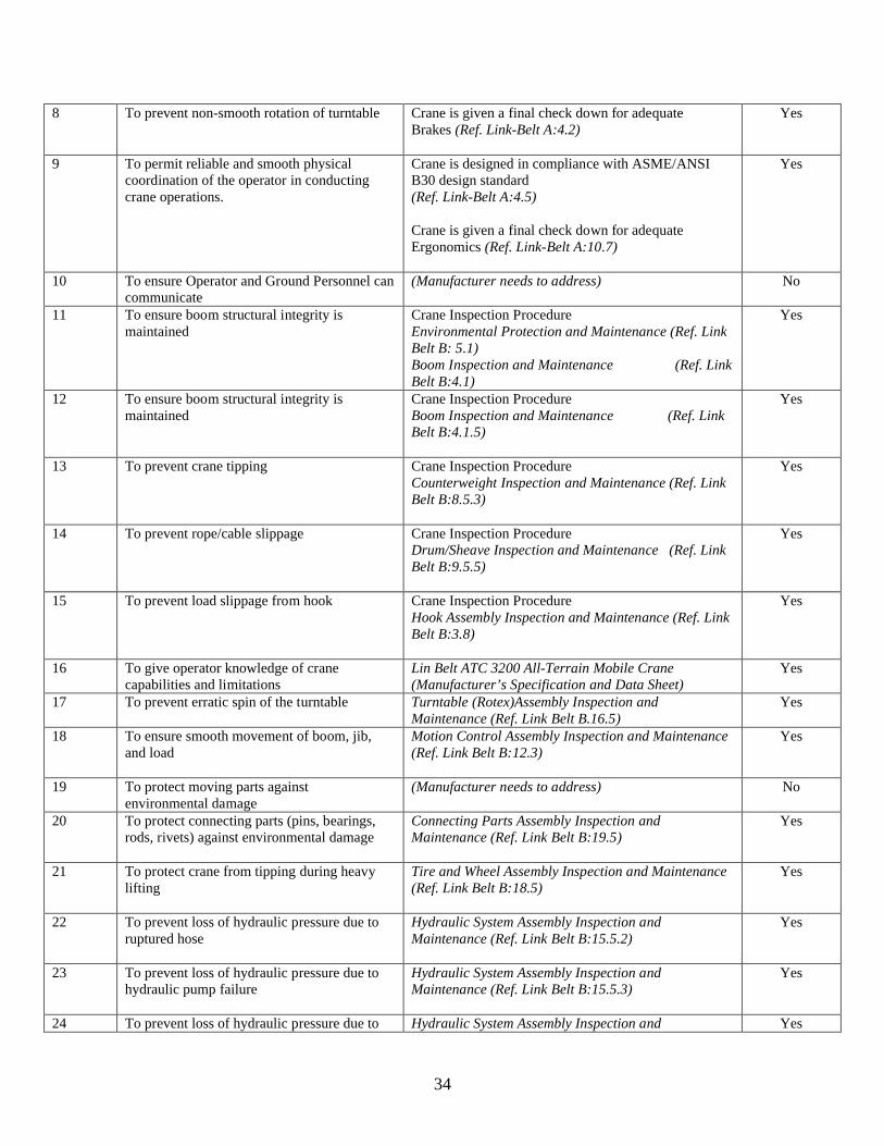
3.2 Requirements Verification Matrix
A Requirements Verification Matrix allows one to formally verify if and how the top-level requirements are met through a specific design implementation. For this report, the Link Belt crane design and operational specifications were matched up against acceptable standard practice and design for hydraulic cranes as designated by the American Society of Mechanical Engineers (ASME) and American National Standards Institute (ANSI). The end result of the verification matrix is to find requirements that cannot be verified or have not been implemented.
Table 4 Requirements Verification Matrix
Req. # Main Requirement System Requirement Reference Verified1 To protect against tipping due to excessive
moment loadingCrane is designed in compliance with ASME/ANSI B30 design standard(Ref. Link-Belt A:4.5)
Yes
2 To protect against accidental lowering of boom
(Manufacturer needs to address) No
3 To prevent backward crane tipping Crane is designed in compliance with ASME/ANSI B30 design standard(Ref. Link-Belt A:4.5)
Yes
4 To prevent buckling of outriggers Crane is designed in compliance with ASME/ANSI B30 design standard(Ref. Link-Belt A:4.5)
Yes
5 To prevent crane tilt Crane is designed in compliance with ASME/ANSI B30 design standard(Ref. Link-Belt A:4.5)
Crane is given a final check down of its wheel and suspension system before delivery to operator(Ref. Link-Belt A:7.13)
Yes
6 To prevent rope damage Crane is designed in compliance with ASME/ANSI B30 design standard(Ref. Link-Belt A:4.5)
Crane is given a final check down for adequate rope length and quality before delivery to operator(Ref. Link-Belt A:8.1)
Yes
7 To prevent accidental load crashing Crane is designed in compliance with ASME/ANSI B30 design standard(Ref. Link-Belt A:4.5)
Crane is given a final check down for adequate Drum (Ref. Link-Belt A:4.1)Rope (Ref. Link-Belt A:8.1)Thermal rating (Ref. Link-Belt A:7.1)Ergonomics (Ref. Link-Belt A:10.5)Power supply(Ref. Link-Belt A:5.1)
Yes
34
8 To prevent non-smooth rotation of turntable Crane is given a final check down for adequate Brakes (Ref. Link-Belt A:4.2)
Yes
9 To permit reliable and smooth physical coordination of the operator in conducting crane operations.
Crane is designed in compliance with ASME/ANSI B30 design standard(Ref. Link-Belt A:4.5)
Crane is given a final check down for adequateErgonomics (Ref. Link-Belt A:10.7)
Yes
10 To ensure Operator and Ground Personnel can communicate
(Manufacturer needs to address) No
11 To ensure boom structural integrity is maintained
Crane Inspection ProcedureEnvironmental Protection and Maintenance (Ref. Link Belt B: 5.1) Boom Inspection and Maintenance (Ref. Link Belt B:4.1)
Yes
12 To ensure boom structural integrity is maintained
Crane Inspection ProcedureBoom Inspection and Maintenance (Ref. Link Belt B:4.1.5)
Yes
13 To prevent crane tipping Crane Inspection ProcedureCounterweight Inspection and Maintenance (Ref. Link Belt B:8.5.3)
Yes
14 To prevent rope/cable slippage Crane Inspection ProcedureDrum/Sheave Inspection and Maintenance (Ref. Link Belt B:9.5.5)
Yes
15 To prevent load slippage from hook Crane Inspection ProcedureHook Assembly Inspection and Maintenance (Ref. Link Belt B:3.8)
Yes
16 To give operator knowledge of crane capabilities and limitations
Lin Belt ATC 3200 All-Terrain Mobile Crane (Manufacturer’s Specification and Data Sheet)
Yes
17 To prevent erratic spin of the turntable Turntable (Rotex)Assembly Inspection and Maintenance (Ref. Link Belt B.16.5)
Yes
18 To ensure smooth movement of boom, jib, and load
Motion Control Assembly Inspection and Maintenance(Ref. Link Belt B:12.3)
Yes
19 To protect moving parts against environmental damage
(Manufacturer needs to address) No
20 To protect connecting parts (pins, bearings, rods, rivets) against environmental damage
Connecting Parts Assembly Inspection and Maintenance (Ref. Link Belt B:19.5)
Yes
21 To protect crane from tipping during heavy lifting
Tire and Wheel Assembly Inspection and Maintenance(Ref. Link Belt B:18.5)
Yes
22 To prevent loss of hydraulic pressure due to ruptured hose
Hydraulic System Assembly Inspection and Maintenance (Ref. Link Belt B:15.5.2)
Yes
23 To prevent loss of hydraulic pressure due to hydraulic pump failure
Hydraulic System Assembly Inspection and Maintenance (Ref. Link Belt B:15.5.3)
Yes
24 To prevent loss of hydraulic pressure due to Hydraulic System Assembly Inspection and Yes

35
hydraulic cylinder damage Maintenance (Ref. Link Belt B:15.5.4)
25 To prevent loss of hydraulic pressure due to broken hydraulic filter
Hydraulic System Assembly Inspection and Maintenance (Ref. Link Belt B:15.5.7)
Yes
Using the Requirements Verification Matrix, the following three requirements were not met by the Link Belt design and operational specifications:
Req. # Main Requirement System Requirement Reference Verified2 To protect against accidental lowering of
boom(Manufacturer needs to address) No
10 To ensure Operator and Ground Personnel can communicate
(Manufacturer needs to address) No
19 To protect moving parts against environmental damage
(Manufacturer needs to address) No
Table 5 Unmet Requirements

36
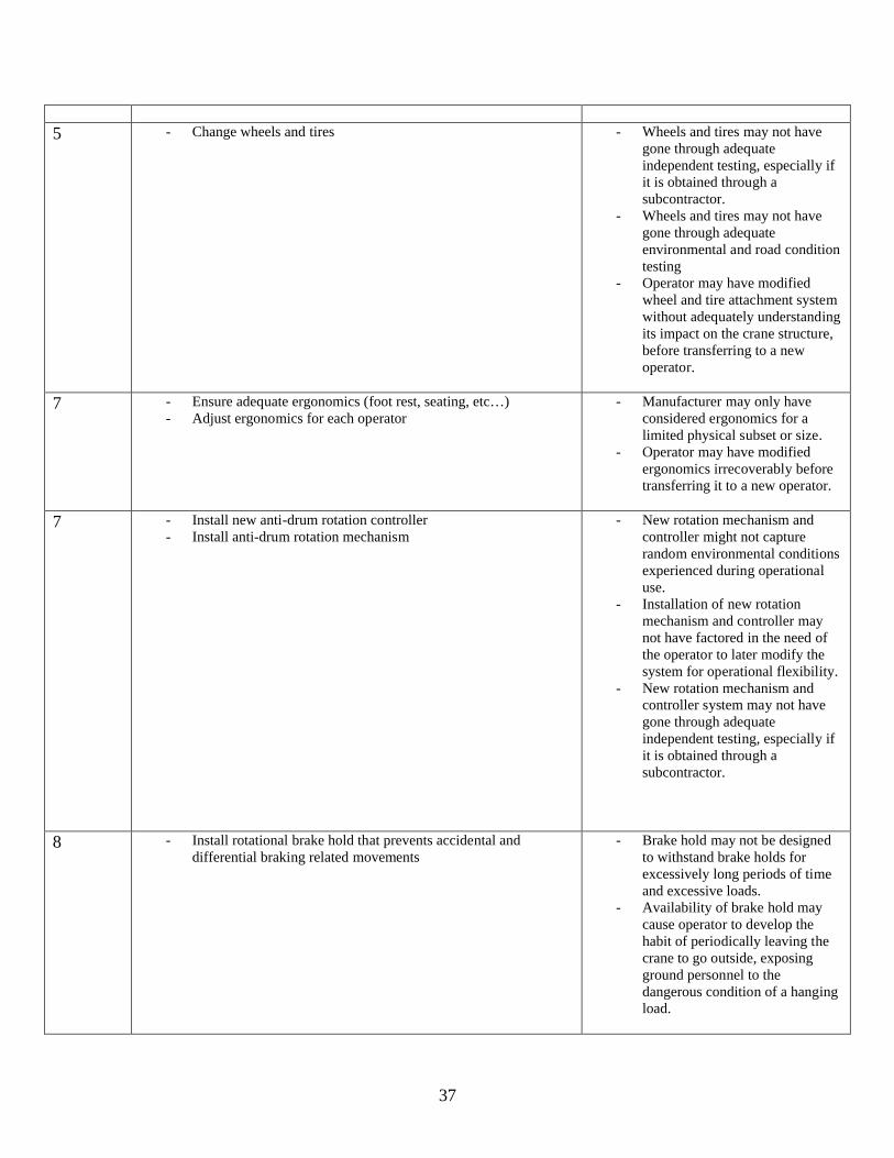
3.3 Requirements Constraint and Analysis
Requirements Constraint and Analysis (RCA) checks for important safety critical requirements and then analyzes them for limitations, feasibility, and ease of implementation. The purpose of RCA is to see how well the requirements are developed and the extent to which they can be realistically and practically implemented. The following are some of the more important safety critical hydraulic crane requirements analyzed using RCA.
Req. # Derived Requirement RCA2 - Install new braking system
- Test braking at the extremes of load and range- Test complete braking hydraulic system
- New braking system might have inadequate life-cycle.
- Accelerated testing of brakes does not capture random environmental conditions experienced during operational use.
- Hydraulic braking system testing might only be exposed to smooth linear loadings, whereas operational load movements are often abrupt.
- New braking system may not have gone through adequate independent testing, especially if it is obtained through a subcontractor.
3 - Install jib stop mechanism- Install boom hoist shutoff mechanism
- New shutoff/stop system might have inadequate life-cycle.
- Accelerated testing of shutoff/stop system does not capture random environmental conditions experienced during operational use.
- Installation of shutoff/stop system may not have factored in the need of the operator to later modify the system for operational flexibility.
- New shutoff/stop system may not have gone through adequate independent testing, especially if it is obtained through a subcontractor.
4 - Reinforce weak outriggers with tension cables - Tension cables can be easily removed or damaged by the operator.
- Tension cables are a less than satisfactory means of compensating for a poorly designed outrigger.
- Tension cables might induce excessive buckling stress beyond the buckling strength of outriggers.
37
5 - Change wheels and tires - Wheels and tires may not have gone through adequate independent testing, especially if it is obtained through a subcontractor.
- Wheels and tires may not have gone through adequate environmental and road condition testing
- Operator may have modified wheel and tire attachment system without adequately understanding its impact on the crane structure, before transferring to a new operator.
7 - Ensure adequate ergonomics (foot rest, seating, etc…) - Adjust ergonomics for each operator
- Manufacturer may only have considered ergonomics for a limited physical subset or size.
- Operator may have modified ergonomics irrecoverably before transferring it to a new operator.
7 - Install new anti-drum rotation controller- Install anti-drum rotation mechanism
- New rotation mechanism and controller might not capture random environmental conditions experienced during operational use.
- Installation of new rotation mechanism and controller may not have factored in the need of the operator to later modify the system for operational flexibility.
- New rotation mechanism and controller system may not have gone through adequate independent testing, especially if it is obtained through a subcontractor.
8 - Install rotational brake hold that prevents accidental and differential braking related movements
- Brake hold may not be designed to withstand brake holds for excessively long periods of time and excessive loads.
- Availability of brake hold may cause operator to develop the habit of periodically leaving the crane to go outside, exposing ground personnel to the dangerous condition of a hanging load.

38
10 - Communication channel between Ground Personnel and Crane Operator
- Wireless communication channel between ground personnel and operator can be degraded by signal interference
- A secondary communication channel between the operator and ground personnel would minimize signal interference.
Table 6 Requirements Constraint and Analysis
39
4.0 Query Modeling and Validation
Traditional UML/SysML is not very useful in an interactive dynamic format. In another words, once a system model has been created in UML, it is essentially a static model, with limited or nonexistent ability to be queried and modified dynamically. It would be greatly beneficial if a system model that has been created can be queried to see how one element is related to another and to see all its dependencies and hierarchy. Querying would enable an engineer to see how a particular element in a UML model is linked to another element, and also how changing one would alter the overall model. Currently this capability is lacking. Although relatively intuitive on small systems, the ability to query and dynamically link various UML models is of huge consequences on large and complex projects.
This report looks at a software algorithm model, the UML Query and Link Analysis Tool (UQLAT), for querying and dynamically linking UML models. Much of this work is done by me as part of an Independent Research and Development (IRAD) effort for my company, Raytheon. As a result of this, I am not allowed to disclose the actual algorithm or screenshots of the querying tool, due to UQLAT being currently used for a Bid Proposal. The UQLAT tool will however be openly disclosed and formally presented at the 2007 INCOSE International Symposium to be held from June 24 – June 28, as part of Raytheon’s demonstration. UQLAT will also be freely available for DOD projects. However, this case study will discuss the data structure, and general algorithm of UQLAT, as well as results of sample queries for the hydraulic crane system presented in this report.
The system model that was used for this report includes the nominal and the off-nominal use cases that were developed in Sections 2.4 and 2.5. Here nominal and off-nominal use cases were modeled using UML type block structures. The particular UML diagram that was used was the Activity diagram. UQLAT has been developed to see the link and relationship between the various elements within the Activity diagrams, both for the nominal and off-nominal use cases. The following six types of queries can be conducted in UQLAT:
1) Query any one element within one phase2) Query one element independently across many phases simultaneously3) Query all the inputs from any one element within one phase4) Query all the outputs from any one element within one phase5) Query the link between any one element and other elements within one
phase6) Query the level of any element within any phase

40
UQLAT is a multi-year program, and therefore is still evolving. As a result, the following are the current limitations of the tool:
- UQLAT is limited to Activity diagrams currently- UQLAT is not capable of linking elements across multiple phases (i.e. how is this
element related to another element across all phases)- UQLAT only dynamically updates individual phases. So if one element changes
in one phase, the change is only reflected for that phase
4.1 Algorithm
UQLAT is a UML query tool that was designed and built using a combination of three primary software tools:
ORACLE – A backend ORACLE database serve is used for the storage organization of UML diagrams and all dataORACLE Forms – A GUI is created using Forms to query UQLAT, as well as display the results of a particular queryPython/SQL – Python and SQL are used to implement the algorithm used for querying and processing
The general sequence of events for a query execution is shown and described below.
Fig. 17 Query Sequence of Events
Query using GUI
Database Processing
Algorithm Processing
Query Display in GUI

41
Step 1 – User enters a query against UQLAT using the custom GUI, by choosing one or more parameters from the GUI window. All parameters, except one, are drop down menu type lists that have their values pre-loaded into the GUI from the ORACLE database, as the UML diagrams were being created. The only non pre-loaded parameter is the Name box. This is a free text search box that will search the entire database for specific keywords.Step 2- The query will be passed onto the ORACLE database that houses the entire UML diagram blocks, connections, text, etc… Step 3 - Here a residing algorithm created in Python/SQL will execute automatically to process the user’s input. The algorithm will continually search the database until it has satisfied all the parameter inputs of the user. Step 4 – Finally, the algorithm will provide the desired output, which will then be displayed in a GUI format back to the end user.
4.2 Data Structure
The key ingredient to UQLAT’s algorithm is the creation of a unique data structure that makes it conducive to be queried and linked. Every time an UML diagram is created in UQLAT’s GUI, it stores each element (a block), connecting arrows, text descriptions, time, hierarchy level, and inputs into the ORACLE database. The basic building block in UQLAT is the block element, which are the rectangular boxes used to describe actions or states in an UML diagram. These block elements, which are stored in the database using the data structure are then processed by the UQLAT algorithm. The algorithm is essentially a structured query mechanism that processes the user’s inputs based on the closest search result and the closest relationship it has to any particular block element. The current capability of UQLAT is limited to activity diagrams. The following table fully describes the data structure used in UQLAT.
Data Element Type Description CommentsBlock ID Mixed
NumericUQLAT automatically assigns each block element a computer generated ID making each block element an unique entity within the UQLAT database
Block ID serves as the primary key for the entire UQLAT database
Name Text Textual description of a particular block element
Has to be text string only
Level Integer The hierarchy level at which a particular block exists
For this report, no more than 3 levels are considered to keep UQLAT manageable
Phase Integer The function that is being performed For this report, this corresponds to Phases 1 through 5
Time Element Integer The sequence of events taking place. This need not be in perfect sequence, but its primary purpose is to tell where one event exists spatially with respect to another
Action/State Binary Action – an event that requires executionState – an event that is the outcome of an execution
A: actionS: state
Input Binary Does a block element have an input 0: no

42
1: yesOutput Binary Does a block element have an output 0: no
1: yesNOI Integer Number of inputsNOO Integer Number of outputsRecursive Binary Does a block have a feedback loop 0: no
1: yesPointer Mixed
NumericThe block element address of where one block points towards
Recursive pointers point to themselves
Table 7 UQLAT Data Structure
4.3 Tool Description
The user interface for UQTAL consists of two different GUI screens that are accessible once UQTAL has been installed along with the entire database and source code elements. The first GUI screen is for the initiation of a query, while the second one displays the results of a query. The user selects an input parameter by selecting them from the drop down menu list or typing in a keyword in the Search Name Box. Once the parameters have been selected, the user can Preview his selections to make sure they are accurate, save the search as a template, or execute the query. The results are displayed in a Query Results Form. The query results form will list the input parameter primary and secondary keys, followed by the query results in the Output section. A clickable diagram link will also take you directly to the UML diagram that the output references.
4.4 Test Query Cases
Five different test query samples are presented here. These five samples are selected to represent a broad spectrum of the type of queries that are possible with the UQLAT software.
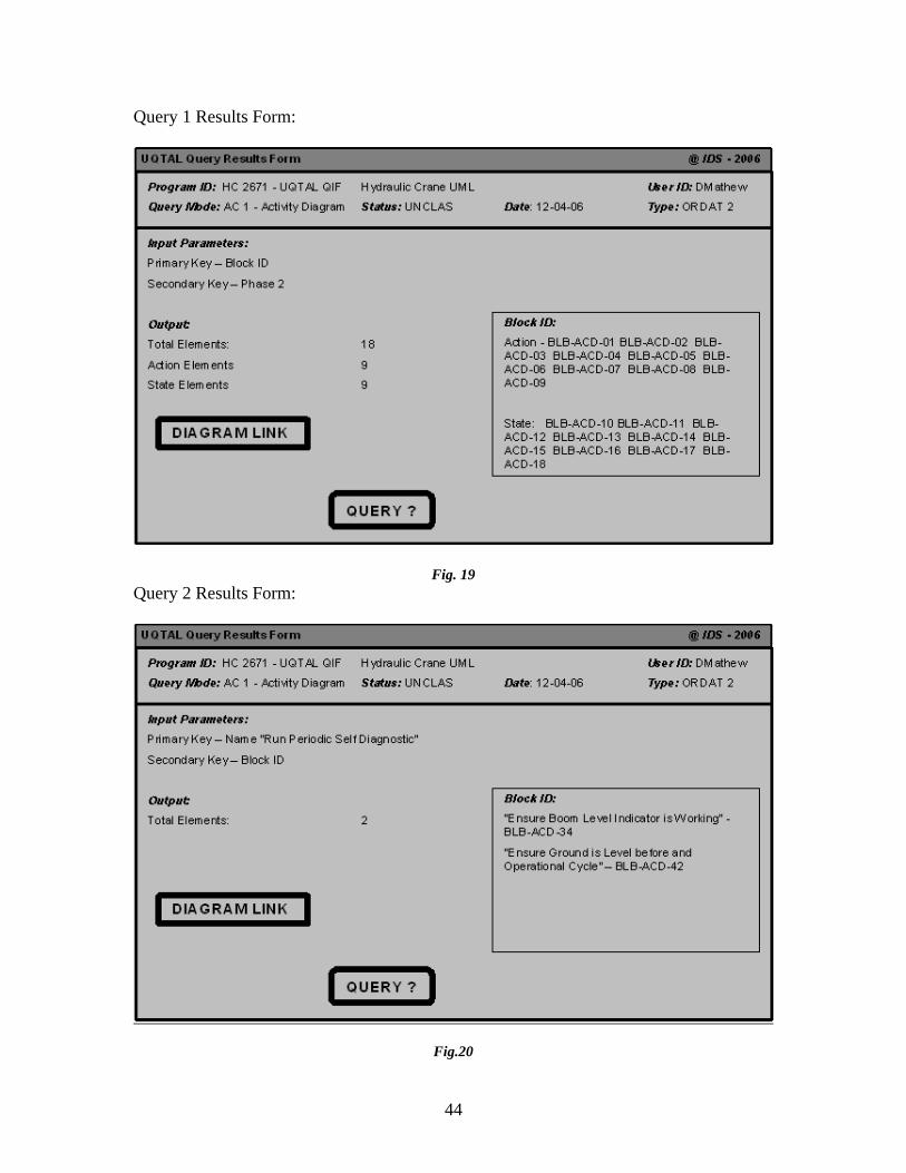
Query 1: How many block elements are there in Phase 2?Solution: 18 total - 9 action and 9 state
Query 2: List all the block elements within one level of block element “Running Periodic Self Diagnostic”
Solution: “Ensure Boom Level Indicator is Working” and “Ensure Ground is Level before an Operational Cycle”
Query 3: List all Phases that have the block element “Level Ground Surface”Solution: Phase 1 and Phase 2
Query 4: What phases have the block elements “Secure Crane”?Solution: Phase 1 and Phase 5,

43
Query 5: What block element is common across Phase 3 and Phase 4?Solution: “Engage Clutch” and “Engage Joystick”
4.5 Test Query Case Results
Query Initiation Form:
Fig. 18 Query Initiation Form
44
Query 1 Results Form:
Fig. 19Query 2 Results Form:
Fig.20

45
Query 3 Results Form:
Fig.21Query 4 Results Form:
Fig. 22

46
Query 5 Results Form:
Fig. 23

47
5.0 CONCLUSION
A detailed system engineering effort goes through system requirements, architecture development, verification, and validation. The current modeling efforts used for systems modeling is not very dynamic and cannot be queried. Without the ability to query and dynamically observe changes, a model does not go very far in aiding a systems engineer. UQLAT has proven itself to be such a tool, and very effective in its ability to transcribe UML models into dynamic and query capable models. Although there are limitations to UQLAT in its current format, primarily in its inability to dynamically link across multiple phases and being limited to activity diagram only, future additions to UQLAT will make it a very versatile tool for systems modeling and analysis.

48
6.0 REFERENCES
1) Austin, Mark. Information-Centric Systems Engineering. Lecture Notes for ENSE 621-622-623. Fall Semester, 2006. University of Maryland, College Park, MD.
2) Uchitel, S., Kramer, J., Magee, J. Incremental Elaboration of Scenario-Based Specifications and Behavior Models using Implied Scenarios January 2004, ACM Transactions ion Software Engineering and Methodology, Vol. 13
3) Fogarty, K., and Austin, Mark. System Modeling and Traceability Applications of the Higraph Formalism September 2006. University of Maryland
4) Magee, Jeff. LTSA: Labeled Transition System Analyser.1999.http://www.doc.ic.ac.uk/~jnm/book/ltsa/LTSA.html
5) Technical Data Specifications and Capacities: Link-Belt ATC 3200 Telescopic Boom All Terrain Crane, March, 2005

49
Appendix A – Definitions
Auxiliary Hoist A supplemental hoisting unit, usually oflower load rating and higher speed than themain hoist.
Axis of Rotation The vertical axis around which the crane's superstructure rotates.
Boom In cranes and derricks, an inclined spar, strut, or other long member supporting the hoisting tackle. Also defined as a structural member attached to the revolving superstructure used for guiding and acting as a support for the load.
Boom Angle Indicator An accessory device that measures the angle of the boom base section centerline to horizontal.
Boom Stops A devise used to limit the angle of the boom at its highest position.
Brake A device used for retarding or stopping motion by friction or power means.
Block Sheaves or grooved pulleys in a frame provided with hook, eye, and strap.
CEHA Cause and Effect Hazard Analysis
Crane A machine consisting of a rotatingsuperstructure for lifting and lowering aload and moving it horizontally on eitherrubber tires or crawler treads.
Counterweight Weights used for balancing loads and the weight of the crane in providing stability for lifting.
Deck The revolving superstructure or turntable bed.

50
Drum The spool or cylindrical member around which cables are wound for raising and lowering loads.
Gantry A structural frame work (also known as an A Frame) mounted on the revolving superstructure of the crane to which the boom supporting cables are reeved.
Headache Ball A heavy weight attached above the hook on a single line or whip line to provide sufficient weight to lower the hook when unloaded.
Holding Brake A brake that automatically sets to prevent motion when power is off.
IMHA Inspection and Maintenance Hazard Analysis
Jib An extension attached to the. boom point to provide added boom length for lifting specified loads.
Load The weight of the object being lifted or lowered, including load block, ropes, slings, shackles, and any other ancillary attachment.
Load Block The assembly of the hook or shackles, swivel, sheaves, pins, and frame suspended from the boom point.
Main Hoist Hoist system or boom used for raising and lowering loads up to maximum rated capacity.
Mechanical Load Brake An automatic type of friction brake used for controlling loads in the lowering direction. This device requires torque from the motor to lower a load but does not impose additional loads on the motor when lifting a load.
OHA Operation Hazard Analysis

51
Outriggers Support members attached to the crane's carrier frame which are used to the crane and may be blocked up to increase stability.
Radius The horizontal distance from the axis of rotation of the crane's superstructure to the center of the suspended load.
Reeving The path that a rope takes in adapting itself to all sheaves and drums of a piece of equipment.
Running Sheave Sheaves that rotate as the hook is raised or lowered
SDHA Scenario Driven Hazard Analysis
Two-Block The condition in which the lower load lock or hook assembly comes in contact with the upper load block or boom point sheave assembly.

52
Appendix B – Link Belt ATC 3200 Technical Data and Specifications

53
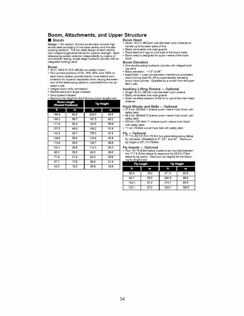
54
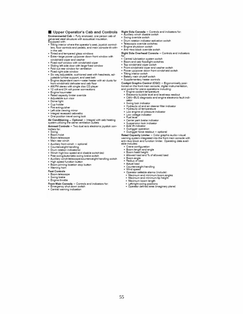
55
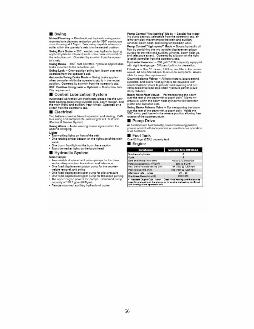
56