quasi z source indirect matrix converter fed induction ...ieeeprojectsmadurai.com/ieee - 2017 -...
TRANSCRIPT

0885-8993 (c) 2016 IEEE. Personal use is permitted, but republication/redistribution requires IEEE permission. See http://www.ieee.org/publications_standards/publications/rights/index.html for more information.
This article has been accepted for publication in a future issue of this journal, but has not been fully edited. Content may change prior to final publication. Citation information: DOI 10.1109/TPEL.2017.2675903, IEEETransactions on Power Electronics
>Manuscript ID TPEL-Reg-2016-09-1832.R1 1
Abstract— This paper describes a flow control of the dye
in the paper mill with the Quasi-Z-Source Indirect Matrix
Converter (QZSIMC) fed induction motor drive. More
than a decade Voltage Source Inverter (VSI) and Current
Source Inverter (CSI) have been used to control the speed
of the induction motor which in turns controls the flow of
dye. Recently Matrix Converter (MC) has been an
excellent competitor for the VSI or CSI for its
compactness. The voltage transfer ratio of the VSI, CSI
and MC has been limited to 0.866. Thus the efficiency of
these converters is less. To improve the voltage transfer
ratio the Quasi-Z- Source Network (QZSN) is to be used
between voltage source and Indirect Matrix Converter
(IMC). Modification in the shoot through duty ratio of the
QZSN varies the voltage transfer ratio greater than 0.866.
The different voltage transfer ratio is needed for different
voltage sag condition. For a variation of the duty ratio of
the QZSN, the fuzzy logic controller has been presented.
To control the IMC vector control with Space Vector
Modulation (SVM) has been presented. This paper
proposes the implementation of QZSIMC adjustable speed
drive for flow control of dye in paper mill during different
voltage sag conditions. A 4kW prototype has been built
and effectiveness of the proposed system is verified with
simulation results and experimental setup. Simulation is
done in MATLAB, Simulink platform. Experimental setup
is done with the aid of TMS320F2812 (Texas Instrument)
processor. The experimental results validate the
maintenance of the speed of induction motor at set
condition, thus controlling the perfect flow of dye in paper
manufacturing technology.
Keywords— Quasi-Z-Source Indirect Matrix Converter,
Fuzzy Logic Controller, Voltage Transfer Ratio, Voltage
Boost Factor, Voltage Sag.
I. INTRODUCTION
ARIABLEspeed induction motor drive finds its
applications in transportation systems, home appliances,
paper and textile mills, rolling and cement mills, pumps, lifts,
compressors, blowers, elevator, conveyors, crushers, machine
tools, and robotics, etc., In the USA, the Electric Power
Research Institute reports that almost 60% to 65% of power
generation is consumed by electric motor drives. In this 75%
of electrical motor drives are pump, fan, and compressor-type
drives. Most of the pumps and fans in industries are used for
fluid flow control. In conventional flow control method, an
induction motor is coupled to the pump and runs at constant
speed. This method causes large energy wastage. Speed
control of the motor by converter can save around 20% energy
at light load [1].
The most generally utilized AC-AC converter topology in
the industry is a traditional DC link voltage source Converter.
DC link capacitor makes the traditional B2BC bulky and
limits service lifetime [2]. Gyugi and Pelly have introduced
the AC-AC converter without DC link component with forced
commutated Cyclo-converter [3]. In 1980, Venturini and
Alesina introduced the Matrix Converter (MC) and they
provided the comprehensive mathematical background [4].
The most impressive alternative to MC is the B2BC due to its
high power density, bi-directional flow of power, reduced
harmonics with sinusoidal waveforms, lower volume and
weight, unity power factor, extended lifetime and dependable
in hostile conditions [5].Dual topologies of MC are Direct
Matrix Converter (DMC) and Indirect Matrix Converter
(IMC). DMC perform single stage conversion (AC-AC), while
the IMC performs two stage conversions (AC-DC-AC)
without DC link capacitor. Even though both converters have
same characteristics, the DMC operates with complex
commutation, while IMC has easy commutation similar to
B2BC [6]. Although many researchers have made significant
process, penetration of MC in industry is less because of its
limitations [7]. Like the B2BC, MC has limited voltage
transfer ratio as 0.866. MC cannot have short circuit the
source and open circuit the load [8].
Much research was carried out to increase the voltage
transfer ratio.Effortless method is to connect a transformer
between the supply and the load. But then again bulky
transformer affects its compactness of the MC. Another way is
to make the MC to operate in over modulation region [9].
However, in this process voltage transfer ratio can be
increased up to unity. Pawel Szcaesniak has proposed matrix
resonant frequency converter which made the voltage transfer
ratio greater than unity. But, in this method synchronization of
MC and resonant source makes control of matrix resonant
frequency converter complex [10]. Peng introduced the Z-
Source Network (ZSN) in the inverter and improves the
Quasi-Z-Source Indirect Matrix Converter Fed
Induction Motor Drive for Flow Control of Dye
in Paper Mill
D.Sri Vidhya, Assistant Professor, Department of Electrical and Electronics Engineering,
K.S.Rangasamy College of Technology, Tiruchengode, India.
Dr.T.Venkatesan, Professor, Department of Electrical and Electronics Engineering, K.S.Rangasamy
College of Technology, Tiruchengode, India.
V

0885-8993 (c) 2016 IEEE. Personal use is permitted, but republication/redistribution requires IEEE permission. See http://www.ieee.org/publications_standards/publications/rights/index.html for more information.
This article has been accepted for publication in a future issue of this journal, but has not been fully edited. Content may change prior to final publication. Citation information: DOI 10.1109/TPEL.2017.2675903, IEEETransactions on Power Electronics
>Manuscript ID TPEL-Reg-2016-09-1832.R1 2
voltage transfer ratio up to 1.12. The ZSN has an additional
advantage that allows short circuit of the source as a
consequence commutation becomes straightforward and
effortless [11]. Quasi-Z-Source Network (QZSN) further
improves the voltage transfer ratio to 4 to 5 times [12].
Incorporation of ZSN/QZSN to DMC/IMC, namely Z-
Source Direct Matrix Converter (ZSDMC) and Z-Source
Indirect Matrix Converter (ZSIMC) increases the voltage
transfer ratio and allows short circuit of the source. An
increase in the voltage transfer ratio provides boost capability
to ZSMC. In ZSDMC, the ZSN is sandwiched between the
source and MC to improve the voltage transfer ratio. The
ZSDMC topology allows entirely silicon solution, but still
requires difficult commutation. In ZSIMC, the ZSN can be
placed in the AC source side or in the DC link. ZSN/QZSN
combined to the IMC’s intermediate DC link results in a not
entirely silicon solution which increases its size and
inductance and capacitance weight in the DC link [13-14].
Integration of ZSN/QZSN into IMC’s AC source side has
proposed by Liu Shuo [15] and simplifies the commutation.
Additional input filters are required to avoid higher order
harmonics of source current. Omar Ellabban et al. have
proposed the modified continuous QZSDMC [16, 17] but it
could not avoid the additional input filters. Liu Shuo et al.
added the continuous QZSN to IMC and developed a new
topology called as Quasi-Z-Source Indirect Matrix Converter
(QZSIMC). This QZSIMC eliminates the extra filter and has
high efficiency [18]. But this topology produces higher
voltage stress on the capacitor in the QZSN. As the capacitor
has 60% of failure rate, stress on the capacitor reduces the
lifetime of the converter [19]. This paper focus on the
discontinuous QZSIMC topology as it provides less voltage
stress on the capacitor in the QZSN.
Input source disturbances in QZSIMC have an immediate
reflection on the load. The unbalanced input voltages and
input voltage sag can result in unwanted output harmonic
currents and voltage sag on the load. This can depreciate the
performance of QZSIMC. A fuzzy logic based compensation
method during unbalanced input voltage condition has
improved the output performance of the ZSMC [20]. By
controlling the shoot through duty cycle, the system can
provide the ride through capability to both balanced and
unbalanced sags [21]. In paper [22], voltage sag compensation
has been implemented with boosting of output voltage and
made in-phase with the input voltage. Almost all the literature
paper has set shoot through duty ratio D as 0.1, 0.15 [14], 0.2
[20] and 0.33 [18] resulting in constant boost. Constant boost
is suitable for system with constant voltage sag. But in
practical application voltage sag occurs only for short duration
and it is not constant. The novelty of the paper is variable
boost with fuzzy controller. Variable boost function was
achieved in paper [23] with fuzzy controller only in
simulation. But, its simulation results show more fluctuation
in the source voltage. In this paper, fuzzy controller in paper
[23] was tuned and better results in simulation were achieved.
Additionally it has been also compared with PI controller to
prove the better performance of fuzzy controller. The
proposed system was implemented in hardware to applied
flow control of dye in the paper production process. The
Seshasayee Paper and Board (SPB) Limited have its own
power generation plant in which there is frequent occurrence
of voltage sags. In SPB Limited Induction motor acquires
almost 80% of the adjustable speed drive for different flow
control of materials. This paper focus on the flow control dye
based on Gram per Square Meter (GSM) of producing paper
in SPB limited. In this paper, implementation of the PI and
fuzzy controller for QZSIMC is done in simulation and fuzzy
controller has been implemented in hardware using 4KW
induction motor. In Section II, the novelty of the proposed
system and its application in dye pump has been explained. In
Section III, topology, working principle of QZIMC fed
induction motor drive and the Space Vector Modulation
pattern for both rectifier and inverter is elucidated. Section IV
elucidates the proposal of a fuzzy logic controller for variable
voltage gain. In Section V, the simulation results of the
presented fuzzy-based QZSIMC are explained in detailed
manner. Section VI presents the experimental implementation
and the results of the QZSIMC fed induction motor with DSP
processor TMS320F2812 (Texas Instrument). In Section VII,
the conclusion has been presented.
II. PROPOSED QZSIMC WITH VARIABLE SHOOT
THROUGH DUTY RATIO D APPLIED TO DYE PUMP
Flow of dye depends on the speed of induction motor. When
voltage sag occurs in the supply voltage it affects the speed of
induction motor. To control the flow of dye even under
voltage sag conditions, the variable boost QZSIMC with fuzzy
controller has been proposed. In this paper a variable boost
capability of the QZSIMC has been tested and analyzed for
different voltage sag conditions. Fig. 1 shows the voltage fed
QZSIMC fed induction motor coupled to dye pump. The
topology of QZSIMC has six parts. It has filter, QZSN,
rectifier, inverter, induction motor and dye pump. The PI
controller or Fuzzy logic controller determines the shoot
through duty ratio D of QZSN and rectifier side modulation
index mr. Inverter side modulation index mi of the SVM is
controlled with the vector controller. To obtain a controllable
input power factor, Space Vector Modulation (SVM)
technique is required which modulates the rectifier. At the
same time, the output voltage fed SVM is applied to the
inverter to modulate three-phase output voltage.
Fig. 1. Block Diagram of Proposed Fuzzy Controller for Quasi-Z-Source
Indirect Matrix converter fed Induction motor drive controlling the Dye Pump.
Fig. 2 shows the storage tank of dye, pump connected to the
outlet of the tank and the induction motor coupled to the
pump. The dye is transferred from the storage tank and mixed
with pulp. The mixture is transferred to the head box of the
paper machine for the manufacturing of paper. The selected

0885-8993 (c) 2016 IEEE. Personal use is permitted, but republication/redistribution requires IEEE permission. See http://www.ieee.org/publications_standards/publications/rights/index.html for more information.
This article has been accepted for publication in a future issue of this journal, but has not been fully edited. Content may change prior to final publication. Citation information: DOI 10.1109/TPEL.2017.2675903, IEEETransactions on Power Electronics
>Manuscript ID TPEL-Reg-2016-09-1832.R1 3
Dye pump has flow capacity of 5 liters per minute for full
speed of an induction motor.
Fig. 2. Real time connection of the dye storage tank, dye pump and induction
motor.
Table I shows the relation between the GSM, flow of dye
and the speed of induction motor. Flow of pulp, dye and starch
determines the GSM and color shading of the paper. Thus the
accuracy of the flow of materials determines the quality of
paper. The proposed system presents the accurate flow of the
dye even under different voltage sag conditions. TABLE I
DYE PUMP (PUMP FLOW CAPACITY 5 LIT/MIN -100%)
N % Speed of Induction
Motor
% Flow of dye in
the pump
GSM of
Paper
1 96 100 120
2 70.8 87.2 80
3 60.6 74.5 75
4 48.8 61.6 70
5 36.4 48.1 65
6 22.7 29.1 60
III. QUASI-Z-SOURCE INDIRECT MATRIX CONVERTER FED
INDUCTION MOTOR DRIVE
A. Topology of the QZSIMC
Fig. 3 shows the topology of the discontinuous QZSIMC
fed induction motor. Two capacitors (Cx1, Cx2), two inductors
(Lx1, Lx2) and one of bidirectional switches (Sx) has been
connected to form QZSN for any one of phase x; x = a, b, c.
Similarly, three QZSN has been connected to the three phase
supply [24].
Fig. 3.The topology of voltage fed Quasi-Z-Source Indirect Matrix converter
fed Induction motor drive.
B. Operating Principle of the QZSIMC
QZSIMC operates in two states namely Non-Shoot-
Through (NST) and Shoot-Through (ST) state. One switching
period Ts has NST and ST state. Tnst and Tstare the time period
of NST and ST state. Shoot through duty ratio is well-defined
as D=Tst/Ts. In NST state the switches (Sx) is closed.
Fig. 4 represents the equivalent circuit of QZSIMC in NST
state. The input voltage of each phase is the sum of the output
voltage and the voltage across the two capacitors in each
phase as in equation (1). During this state, the inductor is
parallel to the capacitor. Hence, the inductor discharges to the
capacitor and the corresponding equation (2).
2
2
2
1
1
1
'
''
''
2
2
2
1
1
1
' Ca
Cc
Cb
Ca
Cc
Cb
ac
cb
ba
Cc
Cb
Ca
Cc
Cb
Ca
ca
bc
ab
V
V
V
V
V
V
V
V
V
V
V
V
V
V
V
V
V
V (1)
2
2
2
2
2
2
,
1
1
1
1
1
1
Lc
Lb
La
Cc
Cb
Ca
Lc
Lb
La
Cc
Cb
Ca
V
V
V
V
V
V
V
V
V
V
V
V (2)
Fig. 4.Equivalent circuit of QZSIMC during NST State.
In ST state the switches (Sx) opens and the upper three
switches of the rectifier (SaU, SbUandScU) are shorted. As the
switches (SaU, SbUandScU) closed the output voltage becomes
zero in the equation (1) in the ST state and it can be rewritten
as in the equation (3). As the switches (Sx) opened, the
inductor charges and its equation are represented in (4).
2
2
2
1
1
1
2
2
2
1
1
1
Ca
Cc
Cb
La
Lc
Lb
La
Lc
Lb
Cc
Cb
Ca
ca
bc
ab
V
V
V
V
V
V
V
V
V
V
V
V
V
V
V (3)
2
2
2
1
1
1
2
2
2
1
1
1
Cc
Cb
Ca
Lc
Lb
La
Lc
Lb
La
Cc
Cb
Ca
V
V
V
V
V
V
V
V
V
V
V
V (4)
Due to the symmetry of QZSN, voltage across the inductor
and capacitor are equal as given in equation (5).
2
2
2
1
1
1
1
1
1
2
2
2
,
Ca
Cc
Cb
Cc
Cb
Ca
Lc
Lb
La
Lc
Lb
La
V
V
V
V
V
V
V
V
V
V
V
V (5)
In steady state, the average voltage across the inductor and
the average current across the capacitor for one switching
period should be equal to zero. The voltage boost factor of
QZSIMC can be expressed as (6),
Dv
vB
i
mqz
21
1
(6)
Where Bqz is the voltage boost factor and D is shoot through
duty ratio of QZSN. The voltage gain G of the proposed
QZSIMC is computed by equation (7),
mBG qz (7)
0885-8993 (c) 2016 IEEE. Personal use is permitted, but republication/redistribution requires IEEE permission. See http://www.ieee.org/publications_standards/publications/rights/index.html for more information.
This article has been accepted for publication in a future issue of this journal, but has not been fully edited. Content may change prior to final publication. Citation information: DOI 10.1109/TPEL.2017.2675903, IEEETransactions on Power Electronics
>Manuscript ID TPEL-Reg-2016-09-1832.R1 4
Where m=mr mi is the modulation index of the indirect matrix
converter, mr is the modulation index of the source side
rectifier, and mi is the modulation index of the load side
inverter. From equation (6), it is evident that the voltage boost
factor Bqz depends on the shoot through duty ratio D. The
voltage gain G can be varied by adjusting the shoot through
duty ratio D. The voltage gain G of proposed QZSIMC can be
greater than unity. It depends on modulation index m and
boost factor Bqz. The shoot through duty ratio D depends on
the modulation index mr of rectifier is expressed in the
equation (8) for maximum voltage boost factor by the [14] as,
rmD 1 (8)
From, equation (6), (7) and (8) and assuming mi as unity,
voltage gain G is expressed as on equation (9).
imD
DG
21
1
(9)
C. Design parameter of QZSN
Inductor voltage and capacitor current can be written
as equation (10).
ccLL VciandiLV (10)
During NST state, the capacitor voltage is equal to inductor
voltage and during ST state the capacitor current is equal to
inductor current. Thus the change in inductor current and
change in capacitor voltage can be written as equation (11).
C
TiVand
L
TVi stL
cnstc
L (11)
Using equations (1) to (6), the change in inductor current and
change in capacitor voltage can be written as equation (12).
is
cis
L iC
DT
D
DVandV
L
TD
D
Di
21
1)1(
12
(12)
where Vi and ii are the voltage and current of the voltage
source, respectively. The designed inductor current ripple ratio
ri and capacitor voltage ripple ratio rcare 0.25 and
0.05.AsΔiL<riiL and ΔVc<rcVcthe designed inductor and
capacitor are given by equation (13).
Zr
mTDCand
mr
ZDTL
c
s
i
s )1( (13)
whereZ is the load impedance. While assuming that thevoltage
source is having unit power factor, ii |Z| =Vim.
D. Space Vector Modulation
In rectifier switch mode, there are two operating states
namely active vector and zero vector states. In order to realize
boost voltage in the QZSN, shoot through is being inserted in
the zero vector state which is shown in Table II. In order to
obtain boost voltage output during shoot through state, three
phase AC supply is short circuited [25].The SVM vector time
periods are calculated by (14).
sszr
sstst
srr
srr
TTTTT
TTTTconstT
TmT
TmT
sin3
sin
(14)
Where mr is the modulation index of the source side rectifier,
is the input current vector angle and and are
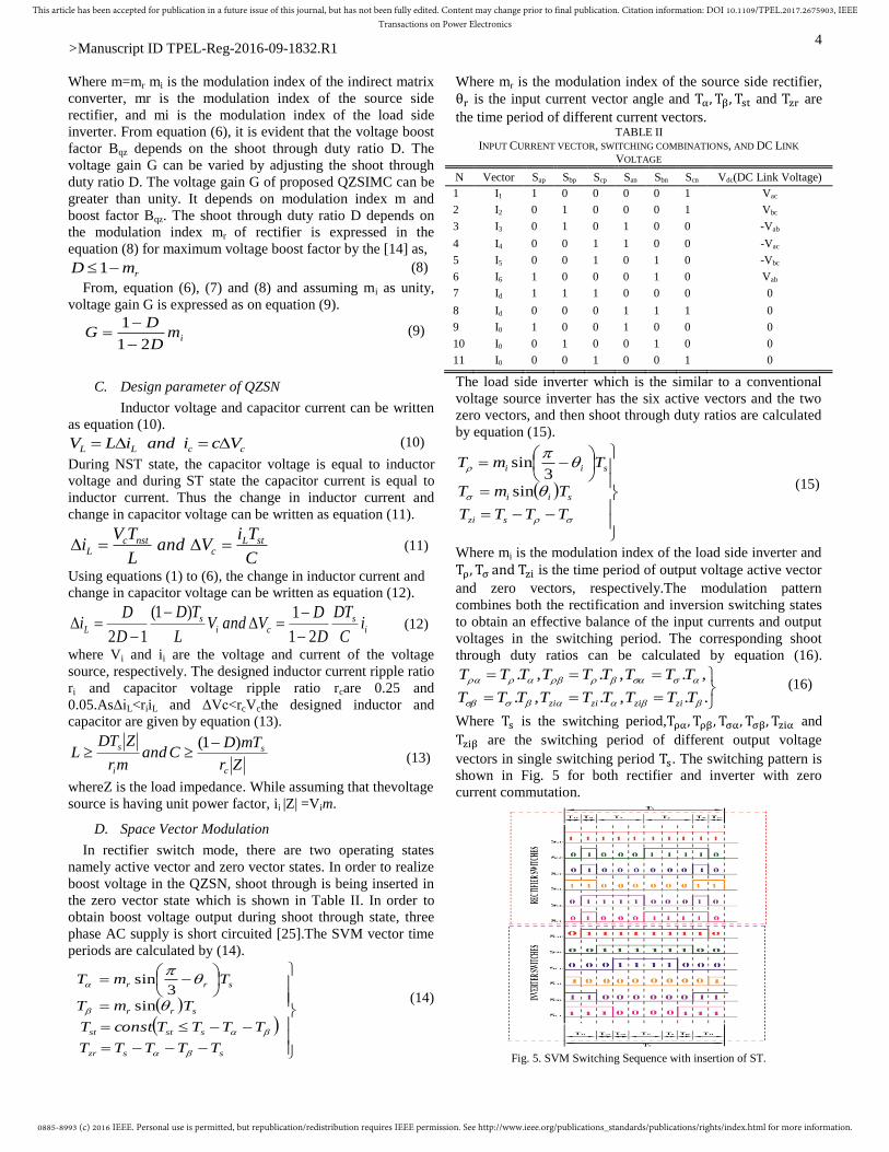
the time period of different current vectors. TABLE II
INPUT CURRENT VECTOR, SWITCHING COMBINATIONS, AND DC LINK
VOLTAGE
N Vector Sap Sbp Scp San Sbn Scn Vdc(DC Link Voltage)
1 I1 1 0 0 0 0 1 Vac
2 I2 0 1 0 0 0 1 Vbc
3 I3 0 1 0 1 0 0 -Vab
4 I4 0 0 1 1 0 0 -Vac
5 I5 0 0 1 0 1 0 -Vbc
6 I6 1 0 0 0 1 0 Vab
7 Id 1 1 1 0 0 0 0
8 Id 0 0 0 1 1 1 0
9 I0 1 0 0 1 0 0 0
10 I0 0 1 0 0 1 0 0
11 I0 0 0 1 0 0 1 0
The load side inverter which is the similar to a conventional
voltage source inverter has the six active vectors and the two
zero vectors, and then shoot through duty ratios are calculated
by equation (15).
TTTT
TmT
TmT
szi
sii
sii
sin3
sin
(15)
Where mi is the modulation index of the load side inverter and
is the time period of output voltage active vector
and zero vectors, respectively.The modulation pattern
combines both the rectification and inversion switching states
to obtain an effective balance of the input currents and output
voltages in the switching period. The corresponding shoot
through duty ratios can be calculated by equation (16).
..,.,.
,.,.,.
TTTTTTTTT
TTTTTTTTT
zizizizi
(16)
Where is the switching period, and
are the switching period of different output voltage
vectors in single switching period . The switching pattern is
shown in Fig. 5 for both rectifier and inverter with zero
current commutation.
Fig. 5. SVM Switching Sequence with insertion of ST.

0885-8993 (c) 2016 IEEE. Personal use is permitted, but republication/redistribution requires IEEE permission. See http://www.ieee.org/publications_standards/publications/rights/index.html for more information.
This article has been accepted for publication in a future issue of this journal, but has not been fully edited. Content may change prior to final publication. Citation information: DOI 10.1109/TPEL.2017.2675903, IEEETransactions on Power Electronics
>Manuscript ID TPEL-Reg-2016-09-1832.R1 5
IV. CONTROL SCHEME BASED ON FLC
In QZSIMC boost factor B and the gain G depend on the
modulation index (m) and shoot through duty ratio D. The
constant modulation index (m) and shoot through duty ratio
D is appropriate for the balanced source, constant load and
constant speed operation. Modulation index m=mr.mi.
A. Control Scheme for Inverter
The vector controller provides control action over the outer
speed loop and inner current loop over with its q-axis
component and d-axis component thereby providing error
free speed tracking. The vector controller fixes the
modulation index (mi) of the load side inverter. When there
is a drop in input voltage, the DC link voltage is being
affected which thereby affects the performance of the vector
controlledinverter fed induction motor drive. Therefore, DC
link voltage plays a major role in the performance of the
QZSIMC. Quasi-Z-Source Network (QZSN) and source side
rectifier decide the DC link voltage. Further, PI and fuzzy
logic controllers are implemented to optimize shoot through
duty ratio D and source side rectifier modulation index (mr),
thereby deciding the gain (G) of the QZSN.
B. PI Controller for Rectifier
Simple proposal and integral controller has been
implemented to decide the shoot through duty ratio D and
source side rectifier modulation index (mr) based on the input
voltage sag conditions. Error in the input voltage and change
in error in the input voltage are fed as input variable to the PI
controller. Shoot through duty ratio D is the output variable of
the PI controller. Using PI tuner in the Matlab Simulink
software the gain of the controller was tuned with Ziegler-
Nichols which robustly stabilize the system.
C. Fuzzy Logic Controller for Rectifier
Fuzzy logic controller structure is shown in Fig. 6.
Fig. 6. Structure of Fuzzy Logic Controller
The design steps are as follows
Step 1: Initial step is to set the inputs and outputs variables.
The input variables that are considered are the Input voltage
error and Speed error. The output variable, shoot through duty
ratio D is being considered.
Step 2:Fuzzification forms the process of converting the
input from numerical or crisp value into fuzzy values and the
outputs from fuzzy value to crisp value. For the conversion
process of crisp values to linguistic terms, fuzzy membership
functions are used. A fuzzy variable contains many fuzzy
subsets which depend on the number of linguistic terms used.
Each of the fuzzy subsets represents one linguistic term which
allows its members to have different grade of membership,
whereby the membership value lies in the interval [0, 1].
Linguistic values chosen for input and output variable are
represented in Table III. TABLE III
FUZZY SET LINGUISTIC TERMS
Parameter Fuzzy Set Expression
Input NB Negative Big
NS Negative Small
Z Zero PS Positive Small
PB Positive Big
Output VL Very Low L Low
M Medium
B Big VB Very Big
Step 3: This step defines fuzzy membership functions.
Based on the designer’s preference and experience, the shape
of the fuzzy membership function is defined. The triangular
shape has been chosen as it provides easy representation, less
computation time and damping of oscillation. Triangular input
and output membership function are selected from the defined
range as shown in Fig. 7.
(a)
(b)
(c)
Fig. 7. Membership function (a) Input –voltage error “VE” (b) Input- Speed
Error “SE”(c) Output –Shoot through Duty ratio “D”
The universe of discourse for fuzzy logic controller is
normalized between [-4, 4] for input and between [0, 0.5] for
output. Linguistic variable NB and PB for inputs are made left
open and right open to incorporate the negative infinite and
positive infinite values. Thus, two input scaling factors
namely VE and SE and one output scaling factor namely D
has to be designed. Input supply voltage to the system is
sinusoidal 230 V. Thus the possible input voltage error range
is from -230 to 230 voltages. Thus voltage error range from [-
160,160] has been scaled down as [-4, 4] from NS to PS. The
range of the NB has been chosen as -230 to -160 with left
open and the range of the PB has been chosen as 160 to 230
Fuzzy Controller
Fuzzifier
Rule Base
Decision Making
Data Base
Defuzzifier
Voltage
error Duty Ratio D
QZSN
SVM for Rectifier
1-D
Speed
error
Input -Voltage Error “VE”
NS ZE NB PS PB
-4 -3 -2 -1 0 1 2 3 4
1
Input -Speed Error “SE”
NS ZE NB PS PB
-4 -3 -2 -1 0 1 2 3 4
1
L M VL B VB
Output - Shoot through Duty Ratio “D”
1
0
0 0.08 0.16 0.24 0.32 0.4 0.48

0885-8993 (c) 2016 IEEE. Personal use is permitted, but republication/redistribution requires IEEE permission. See http://www.ieee.org/publications_standards/publications/rights/index.html for more information.
This article has been accepted for publication in a future issue of this journal, but has not been fully edited. Content may change prior to final publication. Citation information: DOI 10.1109/TPEL.2017.2675903, IEEETransactions on Power Electronics
>Manuscript ID TPEL-Reg-2016-09-1832.R1 6
with right open. The rated speed of the induction motor is
1500 rpm. The possible error range is from -1500 to 1500 rpm.
To achieve minimum speed error the speed error from -50 to
50 has been scaled as -4 to 4 for NS to PS. The range of the
NB has been chosen as -1500 to -25 with left open and the
range of the PB has been chosen as 25 to 1500 with right
open. The range of the shoot through duty ratio has been
limited below 0.5. Thus the range of the shoot through duty
ratio D has been selected from 0 to 0.5.
Step 4: This step defines the rules for selected membership
function. In this case, FLC utilizes fuzzy rules instead of using
a mathematical formula in order to make a decision and
generate control action. The rules are in the form of IF-THEN
statements. For example, IF the input Voltage Error (VE) is
negative small (NS) and the Speed Error (SE) is positive small
(PS) THEN the output is medium (M). 25 rules are framed as
mentioned in Table IV.
TABLE IV
FUZZY RULES
VE
SE
PB PS ZE NS NB
PB VL VL VL L M
PS VL VL L M B
ZE VL L M B VB
NS L M B VB VB
NB M B VB VB VB
Step 5: Finally, the defuzzification process is performed.
Conversion of fuzzy output to crisp output forms the
defuzzification process. Although many defuzzification
methods are available, the most preferred is the centroid
method or center of gravity has been implemented as it is very
precise and provides smooth output. The formula for the
centroid method is given by equation (17).
dzza
z
zdzza
zCentroid
)(
)(
(17)
V. SIMULATION RESULTS AND DISCUSSION
Simulation of the QZSIMC is done with MATLAB Version
7.10.0.499 (R2010a) Simulink in Intel (R) Core (TM) i3 CPU
M370 @ 2.40 GHz Processor. Simulation is done with 4kW
induction motor with rating 415V, 6.5A, 50Hz and 1500 RPM.
To compare the speed control capability of PI and fuzzy
controller different voltage sag condition has been applied to
the supply voltage at 14000 RPM. Fig. 8 and Fig. 9 represents
the speed response of fuzzy and PI controller for 20%, 40%,
60% and 80% voltage sag conditions. Comparison of speed
response for PI and fuzzy controller was made in Fig. 10.
From the speed response Root Mean Square Error (RMSE),
Integral Time Weighted Square Error (ITSE) and Integral
Time Weighted Absolute Error (ITAE) in RPM have been
calculated and tabulated as in Table V. It is evident that the all
the error in the fuzzy controller was less than PI controller.
Thus concluding that speed response of fuzzy controller
wasbetter than PI controller.
Fig. 8. Speed response of PI Controller at different voltage sag conditions.
Fig. 9. Speed response of Fuzzy Controller at different voltage sag
conditions.
Fig. 10.Comparison of speed response of PI and Fuzzy Controller.
TABLE V
COMPARING PI CONTROLLER AND FUZZY CONTROLLER Case PI :
RMSE
Fuzzy:
RMSE
PI :
ITSE
Fuzzy:
ITSE
PI:
ITAE
Fuzzy:
ITAE
Case 1: 20%
voltage sag
7.627 2.413 76.528 24.043 8.718 5.374
Case 2: 40%
voltage sag
9.428 2.405 112.138 24.069 11.006 5.338
Case 3: 60%
voltage sag
12.187 4.794 192.735 30.031 11.976 5.819
Case 4: 80%
voltage sag
120.138 80.391 3960.156 221.27
2702.261 722.465
After proving the superior performance of fuzzy
controller, four casestudies were considered to analyses the
performance of the proposed fuzzy logic based QZSIMC fed
induction motor drive for variable boost function. Different
voltage sag conditions are selected for case study. Case 1, 2, 3

0885-8993 (c) 2016 IEEE. Personal use is permitted, but republication/redistribution requires IEEE permission. See http://www.ieee.org/publications_standards/publications/rights/index.html for more information.
This article has been accepted for publication in a future issue of this journal, but has not been fully edited. Content may change prior to final publication. Citation information: DOI 10.1109/TPEL.2017.2675903, IEEETransactions on Power Electronics
>Manuscript ID TPEL-Reg-2016-09-1832.R1 7
and 4 are simulated with a 20%, 40%,60 % and 80% voltage
sag conditions after 0.2 seconds. The response of the proposed
variable shoot through duty ratio D based on the input voltage
sag and speed error has been discussed. The induction motor
drive is started with no load at a set speed of 1400 RPM.
At 0.1s, the torque load of 10Nm has been applied.
During starting as the speed error are high, the shoot through
occurs. The duty ratio of the shoot through pulse slowly
reduces from 0.4 to 0.1 with repect to the speed error.When
the speed error reaches zero the selection of shoot through
duty ratio become zero. The induction motor drive has been
started with no load at a set speed of 1400RPM and after
transient at 0.25s, the load of 10Nm has been applied.
Case 1: 20% Voltage Sag
In this case voltage sag of 20% occurs after 0.2 s as
shown in the Fig. 11. The input voltage and Vrms voltage
represents a voltage drop of 240 V to 192 V. The Shoot
through pulse starts it firing with a duty ratio of 0.1 after 0.2 s.
The DC link voltage increase as the boosting of voltage is
done after 0.2 s to maintain the speed. The speed response,
outputvoltage, output current and torque even after the 20 %
voltage sag is very good and the motor speed is maintained at
1400 RPM. Thus for a 20% voltage sag the proposed system
works well.
Case 2: 40% Voltage Sag
In this case voltage sag of 40% occurs after 0.2 s as
shown in the Fig. 12.The input voltage and Vrms voltage drops
from 240 V to 144 V the corresponding shoot through duty
ratio also increase to 0.2 from 0.1 when compared to case1.
The DC link voltage boosted output voltage spiked upto 500 V
to maintain the speed. The speed response even after the 40 %
voltage sag is good. But, there occurs small distortion at 0.22
s. After 0.25 s motor actual speed quickly recovers and speed
is maintained at 1400 RPM.
Case 3: 60% Voltage Sag
In this case voltage sag of 60% occurs after 0.2 s as
shown in the Fig. 13. The input voltage and Vrm voltage drop
of 240 V to 96 V, the selection of shoot through duty ratio
becomes 0.3 after 0.2 s. At 0.22 s the speed oscillation is
higher than case 2 but the speed restores itself after 0.25 s and
speed is maintained at 1400 RPM. The DC link voltage
boosted output voltage spiked upto 500 V to maintain the
speed.
Case 4: 80% Voltage Sag
In this case voltage sag of 80% occurs after 0.2 s as
shown in the Fig. 14. When Vrms voltage drop of 240 V to 48
V , the selection of shoot through duty ratio becomes 0.4 after
0.2 s. At 0.22 s the speed oscillation is higher than case 2 but
the speed restores itself after 0.25 s and speed could not
maintained at 1400 RPM.
Fig. 11.Case 1: QZSIMC with 20% voltage sag: Speed, Input voltage,
Vrms of Phase to ground input Voltage, DC Shoot through pulse, DC
link voltage Output Voltage, Output current and Torque.
Fig. 12.Case 2: QZSIMC with 40% voltage sag: Speed, Input voltage, Vrms of Phase to ground input Voltage, DC Shoot through pulse, DC link voltage
Output Voltage, Output current and Torque.

0885-8993 (c) 2016 IEEE. Personal use is permitted, but republication/redistribution requires IEEE permission. See http://www.ieee.org/publications_standards/publications/rights/index.html for more information.
This article has been accepted for publication in a future issue of this journal, but has not been fully edited. Content may change prior to final publication. Citation information: DOI 10.1109/TPEL.2017.2675903, IEEETransactions on Power Electronics
>Manuscript ID TPEL-Reg-2016-09-1832.R1 8
Fig. 13.Case 3: QZSIMC with 60% voltage sag: Speed, Input voltage, Vrms of
Phase to ground input Voltage, DC Shoot through pulse, DC link voltage Output Voltage, Output current and Torque.
Fig. 14. Case 4: QZSIMC with 80% voltage sag: Speed, Input voltage, Vrms of
Phase to ground input Voltage, DC Shoot through pulse, DC link voltage
Output Voltage, Output current and Torque.
VI. HARDWARE IMPLEMENTATION
Hardware implementation has beed carried out with a 4kW
induction motor as in simulation. Set Speed of induction
motor has been decided with the required flow of the dye. The
flow of the dye is determined from the GSM and shading of
paper. Actual Speed of the induction motor is measured by the
Quadrature Encoder Pulse (QEP) sensor. The actual speed of
induction motor input voltage to the QZSN and the input
voltage of induction motor are the parameters fed to the
TMS320F2812 DSP processor. Embedded C coding has been
used to implement the algorithm for fuzzy controller and the
SVPWM. The program for generation of gate pulses for
QZSN, rectifier and inverter has been loaded into DSP
Processor. A snap shot of the experimental setup of the
proposed system has been shown in the Fig. 15.
Fig. 15.Experimental setup of 4kW prototype for QZIMC fed Induction Motor
Drive.
The Fig. 16, Fig. 17, Fig. 18 and Fig. 19 represents
experimental results of case 1 with 20% voltage sag, case 2
with 40% voltage sag, case 3 with 60% voltage sag and case 4
with 80% voltage sag respectively. The Fig. 16-19 shows the
experimental results of speed, DC link voltage, output voltage
and output current for all the cases. From the Fig. 16-18 it is
evident that the speed of induction motor has been maintained
at 1400 RPM with a tolerance of 2%. Speed of the induction
drop from 1400 RPM to 1200 RPM for 80% voltage drop as
evident from the Fig. 19. DC link voltage was maintained at
650 V for 20% voltage sag form Fig. 16. DC link voltage
wasmaintained at 500 V for both 40% and 60 % voltage sag
form Fig. 17 and Fig. 18. But for the 80% voltage drop the
DC link voltage oscillate from 0 V to 600 V as in Fig. 19. For
better understanding of the experimental results, comparison
of all the cases was made in Table VI. Based on the error in
the speed of induction motor the error in the flow of dye pump
occurs. The percentage error in the flow of dye in the dye
pump for a set flow of 40m3 volume of dye was tabulated in
the Table VI. It is evident that the error is within the
prescribed limit of 5% for 20%,40% and 60% voltage sag. For
80% voltage sag error reaches 12%.
0885-8993 (c) 2016 IEEE. Personal use is permitted, but republication/redistribution requires IEEE permission. See http://www.ieee.org/publications_standards/publications/rights/index.html for more information.
This article has been accepted for publication in a future issue of this journal, but has not been fully edited. Content may change prior to final publication. Citation information: DOI 10.1109/TPEL.2017.2675903, IEEETransactions on Power Electronics
>Manuscript ID TPEL-Reg-2016-09-1832.R1 9
Fig. 16. Experimental results of Case 1: QZSIMC with 20% voltage sag :
Speed in RPM, DC link voltage in V, Input voltage in V, Output Voltage in V
and Output current in A with x axis time as 20 ms/div.
Fig. 17. Experimental results of Case 3: QZSIMC with 40% voltage sag :
Speed in RPM, DC link voltage, Input voltage in V, Output Voltage in V and
Output current in A with x axis time as 20 ms/div.
Fig. 18. Experimental results of Case 2: QZSIMC with 60% voltage sag :
Speed in RPM, DC link voltage in V, Input voltage in V, Output Voltage in V
and Output current in A with x axis time as 20 ms/div.
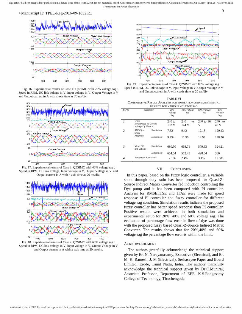
Fig. 19. Experimental results of Case 4: QZSIMC with 80% voltage sag :
Speed in RPM, DC link voltage in V, Input voltage in V, Output Voltage in V
and Output current in A with x axis time as 20 ms/div.
TABLE VI
COMPARATIVE RESULT ANALYSIS FOR SIMULATION AND EXPERIMENTAL
RESULTS FOR VARIOUS VOLTAGE SAG Sl.NO Parameter 20%
Voltage
Sag
40% Voltage
Sag
60% Voltage
Sag
80%
Voltage
Sag
1 Vrms
Input Phase To Ground
Voltage Of Phase A
240 to
192 V
240 to
144 V
240 to 96
V
240 to
48 V
2 RMSE for
Speed
Response
Simulation 7.62 9.42 12.18 120.13
Experiment 9.254 11.50 14.53 148.56
3 Mean DC
link voltage
Simulation 680.50 668.71 579.63 324.21
Experiment 654.54 512.45 498.54 300
4 Percentage Flow error 2.1% 2.4% 3.1% 12.5%
VII. CONCLUSION
In this paper, based on the fuzzy logic controller, a variable
shoot through duty ratio has been proposed for Quasi-Z-
Source Indirect Matrix Converter fed induction controlling the
Dye pump and it has been compared with PI controller.
Analysis for RMSE,ITSE and ITAE were made for speed
response of PI controller and fuzzy controller for different
voltage sag condition. Simulation results indicate the proposed
fuzzy controller has better speed response than PI controller.
Positive results were achieved in both simulation and
experimental setup for 20%, 40% and 60% voltage sag. The
evaluation of percentage flow error in flow of dye was done
with the proposed fuzzy based Quasi-Z-Source Indirect Matrix
Converter. The results shows that for 20%,40% and 60%
voltage sag the percentage flow error is within the limit.
ACKNOWLEDGMENT
The authors gratefully acknowledge the technical support
given by Er. N. Narayanasamy, Executive (Electrical), and Er.
M. K. Ramesh, J. M (Electrical), Seshasayee Paper and Board
Limited, Erode, Tamil Nadu, India. The authors thankfully
acknowledge the technical support given by Dr.C.Muniraj,
Associate Professor, Department of EEE, K.S.Rangasamy
College of Technology, Tiruchengode.

0885-8993 (c) 2016 IEEE. Personal use is permitted, but republication/redistribution requires IEEE permission. See http://www.ieee.org/publications_standards/publications/rights/index.html for more information.
This article has been accepted for publication in a future issue of this journal, but has not been fully edited. Content may change prior to final publication. Citation information: DOI 10.1109/TPEL.2017.2675903, IEEETransactions on Power Electronics
>Manuscript ID TPEL-Reg-2016-09-1832.R1 10
REFERENCES
[1] B. K. Bose, “Global Energy Scenario and Impact of Power Electronics
in 21st Century,” IEEE Transactions on Industrial Electronics, vol. 60, no. 7, pp. 2638-2651, July2013.doi: 10.1109/TIE.2012.2203771.
[2] J.W. Kolar, T. Friedli, J. Rodriguez and P. W. Wheeler, “Review of
Three-Phase PWM AC–AC Converter Topologies,” IEEE Transactions on Industrial Electronics, vol. 58, no. 11, pp. 4988-5006, Nov. 2011.
[3] L. Gyugi, and B. Pelly, “Static Power Frequency Changers, Theory,
Performance and Application,”John Wiley & Sons, New York, USA, 1970.
[4] A. Alesina and M. G. B. Venturini, “Analysis and Design of Optimum-
Amplitude Nine-Switch Direct AC-AC Converters,” IEEE Transactions on Power Electronics, vol. 4, no. 1, pp. 101-112, Jan. 1989.
[5] T. Friedli, J. W. Kolar, J. Rodriguez, P. W. Wheeler, “Comparative
Evaluation of Three-Phase AC–AC Matrix Converter and Voltage DC-Link Back-to-Back Converter Systems,” IEEE Transactions on
Industrial Electronics, vol. 59, no. 12, pp. 4487-4510, Dec. 2012.
[6] P. W. Wheeler, J. Rodriguez, J. C. Clare, L. Empringham and A.
Weinstein, “Matrix Converters: A Technology Review,” IEEE
Transactions on Industrial Electronics, vol. 49, no. 2, pp. 276-288, Apr.
2002. [7] L. Empringham, J. W. Kolar, J. Rodriguez and P.W. Wheeler, J.C.
Clare, “Technological Issues and Industrial Application of Matrix
Converters: A Review,” IEEE Transactions on Industrial Electronics, vol. 60, no. 10, pp. 4260-4271, Oct. 2013.
[8] J. Rodriguez, M. Rivera, J. W Kolar and P. W. Wheeler, "A Review of
Control and Modulation Methods for Matrix Converters,” IEEE Transactions on Industrial Electronics, vol. 59, no. 1, pp. 58-70, Jan.
2012.
[9] Y. Tamai, H. Ohguchi, I. Sato,A. Odaka,H. Mine and J. I. Itoh, “A Novel Control Strategy for Matrix Converters in Over-modulation
Range,” Power Conversion Conference, Nagoya, pp. 1049-1055, Apr.
2007. [10] PawełSzcześniak, "Three-phase AC-AC Power Converters Based on
Matrix Converter Topology, Matrix-reactance frequency converters
concept", Springer-Verlag London 2013. [11] F. Z. Peng “Z-source inverter,” IEEE Transactions on Industry
Applications, vol. 39,no. 2,pp. 504-510,Apr. 2003.
[12] J. Anderson and F. Z. Peng, “Four quasi-Z-Source inverters,” IEEE Power Electronics Specialists Conference, Rhodes, pp. 2743-2749, Jun.
2008.
[13] Ge. Baoming, Lei. Qin, Wei Qian, Fang Zheng Peng, “A Family of Z-Source Matrix Converters,” IEEE Transactions on Industrial
Electronics, vol. 59, no. 1, pp. 35-46, Jan. 2012.
[14] L. Shuo, G. Baoming, H. Abu-Rub , J. Xinjian, and F. Z. Peng, “A novel indirect quasi-Z-source matrix converter applied to induction motor
drives,” in Energy Conversion Congress and Exposition (ECCE), 2013
IEEE, pp. 2440-2444, Sept. 15-19, 2013. [15] L. Shuo, G. Baoming, Y. Xuyang, J. Xinjian, H. Abu-Rub and F. Z.
Peng “A novel quasi-Z-source indirect matrix converter,” International
Journal of Circuit Theory and Applications, 2013. [16] O. Ellabban, H. Abu-Rub and Ge. Baoming, “Field oriented control of
an induction motor fed by a quasi-Z-source direct matrix converter,” Industrial Electronics Society, 39th Annual Conference of the IEEE, vol.
10, no. 13, pp. 4850-4855, Nov. 2013.
[17] O. Ellabban, H. Abu-Rub and Ge. Baoming, “A Quasi-Z-Source Direct Matrix Converter Feeding a Vector Controlled Induction Motor Drive,”
in Emerging and Selected Topics in IEEE Journal of Power Electronics,
vol. 3, no. 2, pp. 339-348, Jun. 2015. [18] L. Shuo, G. Baoming, J. Xinjian, H. Abu-Rub and F. Z. Peng,
“Comparative Evaluation of Three Z-Source/Quasi-Z-Source Indirect
Matrix Converters,” IEEE Transactions on Industrial Electronics, vol. 62, no. 2, pp. 692-701, Feb. 2015.
[19] P. Szcześniak, J. Kaniewski, M. Jarnut, “AC–AC power electronic
converters without DC energy storage: A review,” Energy Conversion and Management, vol. 92, no. 1, Pages 483-497, Mar. 2015.
[20] K. Park, K. B. Lee and F. Blaabjerg, “Improving Output Performance of
a Z-Source Sparse Matrix Converter Under Unbalanced Input-Voltage Conditions,” IEEE Transactions on Power Electronics, vol. 27, no. 4,
pp. 2043-2054, April 2012.
[21] B. Yu, X. Ding, Y. Lu, H. Li and X. Li, "Voltage sags on Quasi-Z-source adjustable-speed drives system," IEEE International Conference
on Mechatronics and Automation, Beijing, pp. 1899-1904, 7-10 Aug.
2011.
[22] M. K. Nguyen, Y. G. Jung and Y. C. Lim, “Single-Phase AC–AC
Converter Based on Quasi-Z-Source Topology,” in IEEE Transactions on Power Electronics, vol. 25, no. 8, pp. 2200-2210, Aug. 2010.
[23] D. Sri Vidhya,T. Venkatesan and N. Kanagaraj, “Fuzzy Logic Controller
for Variable Boost Function in Quasi Z Source Indirect Matrix Converter during Voltage Sag Condition” Int. J. Fuzzy Syst. (2016).
Doi: 10.1007/s40815-016-0221-x.
[24] L. Shuo, G. Baoming, H. Abu-Rub, J. Xinjian and F. Z. Peng, “Modeling, analysis, and motor drive application of quasi – Z source
indirect matrix converter” in the International Journal for Computation
and Mathematics in Electrical and Electronic Engineering, vol. 33,no. 12, pp. 298-319, 2014.
[25] L. Xiong, L. PohChiang,W. Peng and H. Xiaoqing, “Improved
Modulation Schemes for Indirect Z-source Matrix Converter With Sinusoidal Input and Output Waveforms,” IEEE Transactions on Power
Electronics, vol. 27,no. 9,pp. 4039-4050, Sept. 2012.
D.Sri Vidhya was born in chitoor,
Kerala, India, in 1982. She received
B.E degree in Electrical and
Electronics Engineering from Bannari
Amman Institute of Technology,
Sathyamangalam, Tamilnadu, India in
2004 and M.E. degree in Power
Electronics and drives from
K.S.Rangasamy College of
Technology, Tiruchengode, India in
2008. She is currently pursuing the
Ph.D degree in Electrical Engineering
at Anna University, Chennai, India and
working as an Assistant Professor in K.S.Rangasamy College of
Technology, Tiruchengode, India. She has published over 15
research papers in international journals and conferences. Her
research interests are Induction motor drives, Matrix Converters
and Intelligent Techniques.
Dr.T.Venkatesan. was born in Salem,
India, in1971. He received B.E degree in
Electrical and Electronics Engineering
from Regional Engineering College
Tiruchirapalli, Tamilnadu, India in 1997.
He received M.E degree in Power System
Engineering from Annamalai University,
India, in 2002, and received Ph.D. in Anna
University, Chennai, in 2013. Currently he
is working as a Professor in
K.S.Rangasamy College of Technology,
Tiruchengode, India. He has published over 33 research papers
in international journals and conferences. His research interests
are Economic Dispatch, Unit Commitment problem solution
using soft computing techniques, Renewable energy sources,
Induction motor drives and Intelligent Techniques.