quarterly journal9f50f0311489b2d45830-9c9791daf6b214d0c0094462a66… · · 2015-06-30quarterly...
TRANSCRIPT

1 INTECSEA.com
04 > South Stream project
06 > Flow aSSurance SimulationS and hippS deSiGn
08 > BuildinG a "hoBBy-claSS" roV
IN T
hIS
ISSu
E
QuARTERLY
JOuRNALQ4-2011

2 INTECSEA.com
Published by
INTECSEA 15600 JFK Boulevard 9th Floor Houston, TX 77032, USA
Managing Editor
Michelle Lang [email protected]
Contact Information
www.intecsea.com
Global Frontiers has Quick Response (QR) Codes incorporated into this publication. To view expanded articles and links from these codes, please visit the iTunes App Store or the Android Market to choose a QR Reader Application.
Subscribe to INTECSEA's Global Frontiers at www.intecsea.com or scan the code:
Q4 – 2011
Front Cover Image: AUV Deployment – The South Stream Project – Page 4
p.4The South Stream Project INTECSEA and Gazprom apply new levels of technology in the Black Sea.
Inside this Issue
p. 3 President's Letter
p. 9 Arctic News Trenching of Pipelines for Protection
in Ice Environments
p. 10 CNPC – ShenZhen to Hong Kong Submarine Pipeline Project
Nord Stream Pipeline Project Named as Top 5 by Offshore Magazine
p. 11 Inside INTECSEA News, recognitions and events
p. 6 Flow Assurance Simulations Impact HIPPS Design Parameters
Providing a detailed look at how INTECSEA is helping clients through High Integrity Pressure Protection Systems (HIPPS) studies.
p. 8 Building a "Hobby-Class" ROV
Reidar Eliassen takes on the challenge of building a scaled-down model of the real thing–and succeeds–with a creative set of component substitutes.

INTECSEA.com 3GLObAL FRONTIERS Q4-11
"Because of advancement in tools, we have been able to reduce safety factors and increase design efficiency without compromising safety. In fact, safety and reliability have improved since design environments can be more realistically modeled and the response of the design to these environments can be more accurately predicted."
p. 10 CNPC – ShenZhen to Hong Kong Submarine Pipeline Project
Nord Stream Pipeline Project Named as Top 5 by Offshore Magazine
p. 11 Inside INTECSEA News, recognitions and events
Tools
This summer our pool sprang a leak. Record heat and drought had caused our Houston gumbo soil to shift, taking its toll on the underground plumbing. Now, there is quite a bit of plumbing buried around a pool and depending on where the leak is, the consequences can be classified from disastrous to highly aggravating to mildly annoying. Disastrous is a leak in the suction piping connecting to the strainer at the bottom of the pool which would require near destruction of the concrete shell to get to it. Highly aggravating would be a leak in the piping buried deep below the pea gravel concrete deck surrounding the pool; the mildly annoying variety didn’t apply since all my plumbing is beneath concrete.
After some further diagnostics I concluded I would be able to avoid the disaster scenario; the leak was in the return piping underneath the concrete deck. At that point I simply could have hired a contractor to break up the concrete deck, dig up the pipe run, replace the plumbing and pour a new deck. While the financial aspects of this proposition were certainly a consideration, my main motivator to pursue the Do-It-Yourself solution in this circumstance was the prospect of testing out and acquiring a new tool; the rationale being that buying a tool will pay for itself when you consider you might need it again. That is how I have collected quite a large assembly of “barely used” specialty tools which are still awaiting their second use.
Instead of jackhammering the concrete deck I decided to go with the somewhat more civilized route of cutting the deck in 2-ft wide sections and lifting them out one by one, starting at the pool end. As it turned out, I was lucky and had to remove only a couple of sections as the leak was right where the 1.5 inch plastic piping penetrated the pool wall. Relative movement and a poor design resulting in high stress concentrations had cracked the thin-wall pipe. It is amazing it had lasted that long.
What made this job possible (in addition to a fair amount of manual labor) was a concrete saw which is a serious (and highly effective) tool, 6HP gas powered with a 16-inch diamond blade. It is fairly obvious I am a tool aficionado. I collect tools like other people collect fine wines. Over the years I have assembled an eclectic assortment of tools ranging from hydraulic presses to micrometers. I acquire tools to make other tools.
In our engineering business we use powerful tools all the time. Unlike the dumb power tools I am using at home, these are smart, highly sophisticated applications designed and tested to solve complex problems. Although I have never used many of these tools myself, I am intrigued by them since, in many respects, they define our business. In the right hands they help determine technical feasibility and economic viability of deepwater developments.
Recently I had an opportunity to observe the capabilities of advanced CFD (Computational Fluid Dynamics) showing sloshing behavior of the cargo in an LNG carrier down to the level of spray and droplet formations; that is a far cry from the simplified strip theory I grew up with to predict ship motions.
No doubt our abilities to analyze, made possible by exponential increases in computing power, have improved tremendously in the last decades. This comes however with some risks if we are not careful. One risk we are running is putting blind faith in our tools. We should not forget that fantastic engineering feats were achieved with only a slide rule and the theorems and laws of Newton, Castigliano and von-Mises. We launched a man to the moon that way. Intuition and a visceral grasp of the results were needed to do a sense check and validate the results of these computations. When problems become ultra-complex and require even more complex tools to analyze, these attributes may no longer serve us; and the only way to validate our conclusions is to independently verify the results, preferably with different tools; i.e. perform the work twice.
Another trap to avoid is overanalyzing. Not everything requires the most sophisticated tool. Overreliance on these tools can start to diminish efficiency and will cause our engineering instinct to atrophy. I have a large collection of tools at home to accommodate a broad range of needs. Some only require a jigsaw; others a 6HP gasoline powered concrete saw.
Storage is becoming an issue.

4 INTECSEA.com
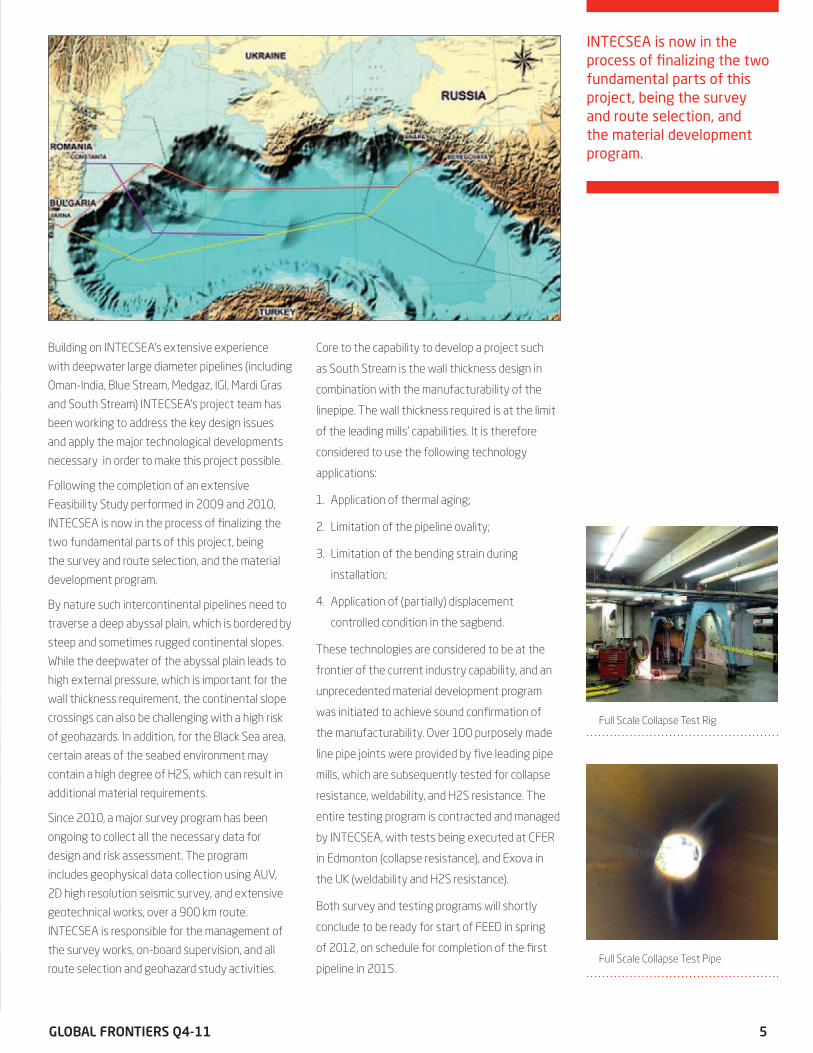
The South Stream Project Takes the Industry Another
Step Forward
by Martijn van Driel
and Alex MayantsWith the realization of Blue Stream pipeline project some 10 years
ago, Gazprom brought the offshore industry to a new level. Since
then, the application of a 24-in pipeline in 2,000m+ water depth has
come to be considered as proven technology. Now, building on the
successful relationship developed on Blue Stream and Nord Stream,
Gazprom subsidiary Giprospetsgaz is working with INTECSEA to
apply a similar approach on the South Stream project, which considers
the use of 32-in diameter in more than 2,200m water depth. To
apply such a large diameter in these water depths involves a step-
out in technology application, but it is within reach. The project will
comprise four parallel pipelines, of over 900 km each.
INTECSEA.com 5GLObAL FRONTIERS Q4-11
INTECSEA is now in the process of finalizing the two fundamental parts of this project, being the survey and route selection, and the material development program.
Building on INTECSEA’s extensive experience
with deepwater large diameter pipelines (including
Oman-India, Blue Stream, Medgaz, IGI, Mardi Gras
and South Stream) INTECSEA’s project team has
been working to address the key design issues
and apply the major technological developments
necessary in order to make this project possible.
Following the completion of an extensive
Feasibility Study performed in 2009 and 2010,
INTECSEA is now in the process of finalizing the
two fundamental parts of this project, being
the survey and route selection, and the material
development program.
By nature such intercontinental pipelines need to
traverse a deep abyssal plain, which is bordered by
steep and sometimes rugged continental slopes.
While the deepwater of the abyssal plain leads to
high external pressure, which is important for the
wall thickness requirement, the continental slope
crossings can also be challenging with a high risk
of geohazards. In addition, for the Black Sea area,
certain areas of the seabed environment may
contain a high degree of H2S, which can result in
additional material requirements.
Since 2010, a major survey program has been
ongoing to collect all the necessary data for
design and risk assessment. The program
includes geophysical data collection using AUV,
2D high resolution seismic survey, and extensive
geotechnical works, over a 900 km route.
INTECSEA is responsible for the management of
the survey works, on-board supervision, and all
route selection and geohazard study activities.
Core to the capability to develop a project such
as South Stream is the wall thickness design in
combination with the manufacturability of the
linepipe. The wall thickness required is at the limit
of the leading mills' capabilities. It is therefore
considered to use the following technology
applications:
1. Application of thermal aging;
2. Limitation of the pipeline ovality;
3. Limitation of the bending strain during
installation;
4. Application of (partially) displacement
controlled condition in the sagbend.
These technologies are considered to be at the
frontier of the current industry capability, and an
unprecedented material development program
was initiated to achieve sound confirmation of
the manufacturability. Over 100 purposely made
line pipe joints were provided by five leading pipe
mills, which are subsequently tested for collapse
resistance, weldability, and H2S resistance. The
entire testing program is contracted and managed
by INTECSEA, with tests being executed at CFER
in Edmonton (collapse resistance), and Exova in
the UK (weldability and H2S resistance).
Both survey and testing programs will shortly
conclude to be ready for start of FEED in spring
of 2012, on schedule for completion of the first
pipeline in 2015.
Full Scale Collapse Test Rig
Full Scale Collapse Test Pipe

6 INTECSEA.com
Figure 1: HIPPS Located at the
Subsea Trees
Introduction With increased development of high pressure-high temperature subsea fields, understanding the performance of subsea High Integrity Pressure Protection Systems (HIPPS) is of key importance.
Recently, INTECSEA has performed HIPPS studies for several of our clients around the world. A significant part of these studies has been a robust flow assurance analysis of the performance of the HIPPS applications. In particular, detailed transient multiphase hydraulic analyses have been performed to both understand the overall system performance and help define key system design parameters.
Using the OLGA transient simulator, INTECSEA has helped our clients define key HIPPS design parameters via detailed analyses of system pressures resulting from all potential HIPPS trigger conditions. The OLGA models have included all key aspects of the fluid and flowpath, including detailed fluid PVT models, wellbores, reservoir inflow performance, HIPPS valves, flowlines, risers, boarding valves, chokes and pressure boosting equipment.
HIPPS Subsea fields are being developed that have shut-in wellhead pressures (SIWPs) that can exceed the desired pressure capacity of the receiving flowline. In these situations, HIPPS are often proposed to protect the downstream piping via isolation to prevent over-pressurization.
A HIPPS is a Safety Instrumented System (SIS) based on a type of Emergency Shutdown (ESD) valve that is controlled via a series of redundant pressure sensors. The system is pre-set to trigger, or activate, at a pressure less than the maximum allowable pressure of the downstream piping to be protected. When the pressure set-point is exceeded, the sensors activate the HIPPS valve to close and protect the downstream system from high pressure. A fortified zone is included immediately downstream of the HIPPS, the length of which is determined by how far the pressure wave travels before the HIPPS valve is closed.
HIPPS allows for downstream flowlines, manifolds, pumps, valves, etc., to be designed with a reduced pressure rating, below the SIWP. With deepwater wellhead pressures approaching (and exceeding) 20 ksi, HIPPS can be used to allow downstream piping to be designed with a pressure rating of 10-15 ksi or lower. For these applications HIPPS can reduce cost, improve project schedule and delivery, and improve system “installability”.
HIPPS Pressure Simulation with OLGA Simulated HIPPS valve performance after a triggering event is demonstrated in Figure 2 (see pg. 7). This example represents the case where the system is activated due to inadvertent closure of a valve located downstream of the HIPPS at time t=0 seconds. The wellhead choke remains open in this example.
As shown in Figure 2, both the wellhead pressure (location 1) and the pressure upstream of the closed valve (location 2) begin climbing immediately as the line packs. This is after an initial pressure surge of ~350 psi at t=0 due to the “water hammer” effect of closing the valve. These pressures continue rising and reach the HIPPS set point (5,500 psig in this case) at t=14 seconds, at which point the HIPPS valve is activated and begins to close. With a prescribed HIPPS valve closure time of 10 seconds, the HIPPS valve is completely closed at t=24 seconds.
With the HIPPS valve closed, the pipeline section downstream of the HIPPS (location 2) is isolated and protected from the high SIWP. The final pressure in the protected section is ~6,700 psig, which is lower than the flowline design pressure of 7,500 psig. Note that the wellhead pressure (location 1) reaches the wellhead shut-in pressure (15,000 psig) in approximately 180 seconds.
Flow Assurance and HIPPS Analysis The graph shown in Figure 2, a result of several prior OLGA runs, represents one of the many outputs of the OLGA analyses and is used to illustrate the system response to one HIPPS trigger scenario. The overall performance of a given
Flow Assurance Simulations Impact hIPPS Design Parameters
by Ronnie Zerpa and Scott Bufton

INTECSEA.com 7GLObAL FRONTIERS Q4-11
system is largely dependent on several key flow assurance and system design parameters. The key to successfully using OLGA results to aid in the HIPPS design is to be certain these parameters and their expected sensitivity ranges are well understood and captured accurately in the OLGA model.
Successful simulation requires an accurate PVT model of the system; particularly important fluid parameters include:
• Gas-oil-ratio, since gas in the system will impact the packing time;
• Water-cut, since oil and water have different moduli of elasticity, and;
• Bubble point, which is important in capturing the flowline pressure build-up rate after a shutdown event, especially if the pressure/temperature state of the fluid crosses the phase envelope boundary.
Other key system design aspects to be considered in the modeling include:
• Valves, subsea pumps, manifolds or other subsea equipment downstream of the potential HIPPS location which have the potential to stop production;
• Choking strategy, i.e., topsides versus subsea choking;
• Hydrate management philosophy and the likelihood of forming a blockage downstream of the HIPPS fortified section;
• Flowline and riser materials of construction and their respective elasticities;
• Bottom-hole pressure recovery after the well is shut-in; and,
• Well flowrates, reservoir pressures, and wellbore productivity indices (PIs), which vary over the life of the field.
Transient analyses and consideration of the above parameters is key to helping define many aspects of the HIPPS design, including: the required HIPPS valve closure time, the HIPPS set point or trigger pressure, the required length of the fortified zone, and feasible values for the pressure rating in
the unfortified (protected) zone. In other words,
transient flow assurance analysis can help in nearly
all aspects of the HIPPS global design.
Simulation Scenarios
During HIPPS screening studies it is critical to
consider all the possible scenarios that could
activate the HIPPS. Selection of these cases is
driven mainly by the field layout and the expected
operating philosophy. Examples of HIPPS triggering
scenarios are many, but can include unplanned
closure of the boarding valve, start-up against
a closed boarding valve, choke failure, a choke
opened in error, and a hydrate or other blockage
downstream of the HIPPS and the fortified zone.
All of these events are simulated with OLGA to
evaluate and define key HIPPS design parameters.
Summary
INTECSEA has performed detailed HIPPS transient
multiphase analyses on a series of projects for our
clients.
For additional information, please see the technical paper “Transient Thermal-Hydraulic Analyses Guide HIPPS Screening, Design Decisions, and Technical Feasibility”, by Ronnie Zerpa and Scott Bufton (IOPF2010-4002, Presented at the 5th International Offshore Pipeline Forum, October 2010, Houston, TX), or contact Scott Bufton at 281-925-2282 or [email protected].
"Through this experience we have acquired expertise and the ability to customize
and apply the above methodology to any subsea or topsides/onshore HIPPS
application. We look forward to the opportunity to
apply our OLGA and HIPPS modeling expertise on our
client’s future projects."
Figure 2: Example of Hipps
Pressure Response After Closure of a
Downstream Valve

8 INTECSEA.com
I have been working in subsea engineering since 1978, so I know quite a bit about real “working class” ROVs costing millions of dollars. You can imagine, that building my own ROV on a budget, turned out to be quite a challenge. Since I did not have access to a lathe or other professional tools at home, I had to use off-the-shelf components. My local home improvement store, Home Depot, became my favorite place to visit to look for components and other necessary tools and supplies.
A typical ROV consists of a structural frame, water- tight housing(s) for the control electronics, an underwater video camera, lights, buoyancy modules, thrusters and an umbilical connecting the ROV to the surface control equipment through an umbilical reel.
The beginning phase of my ROV project often consisted of looking for shelf components, such as thrusters, water tight housings and connectors, online. I quickly realized that the cost for most of these items was completely out of my reach. For example, one ROV thruster used for underwater propulsion that was suitable for my project cost $1,500! The ROV model I was building would need three thrusters; these items alone could have been a showstopper. I was shocked at the price, but not deterred from finishing my project. I figured out that by using a water tight electric motor (from a bilge pump for pleasure boats), a Kort nozzle/propeller assembly (for model boats), and an aluminum coupling connecting the shaft of the electric motor to the propeller shaft, a thruster suitable for my ROV could be built for less than $100.
I also determined the need for a low-cost alternative for the electronic control system, which controls the ROV from the surface. Fortunately, I found a pre-made control system on eBay that was small enough to fit inside the surface control box and the underwater watertight housing. There were several cases like this where inexpensive,
off-the-shelf items were used to substitute rather pricey “professional” underwater and topside components.
The final challenging component was the umbilical. To minimize the diameter and cost of the umbilical, I decided to have the battery that powers the ROV inside the water tight housing. I knew that if the battery was on the surface, the umbilical would have to contain both signal and power leads. The finished product only contains signal leads for control of the ROV, and video signals back to the surface from the built-in color video camera that is the underwater eye of the ROV. The ROV also has built-in underwater lights to illuminate any underwater subjects.
The umbilical is stored on an umbilical reel (also bought from Home Depot), where the control signals pass through a swivel in the center of the reel. This was done so the ROV can be controlled when the reel is turning. This swivel is a telephone cord, untangle swivel, which has sufficient leads to send and receive control signals from the ROV control circuits. It also contains a signal to a buzzer, which is activated in the case that the electronic circuit discovers water inside the water tight housing.
The ROV was tested in a swimming pool and it worked as intended. The water depth was only 5 feet, but the ROV responded very well to the controls sent from the surface control box. In the near future I will take the ROV to a lake where the water tight connections will be fully tested.
The plan is to also install an underwater 3-D video camera on the front frame of the ROV. This video will then be transferred to my computer as soon as the ROV is back on dry land.
All this looking around for suitable components took a long time and many trips to various stores and searches online, but in the end it all came together. I’m proud to say that I now have a fully functional “hobby-class” ROV.
building a “hobby-Class” Remotely Operated under Water Vehicle (ROV)
by Reidar Eliassen
The ROV responded very well at a
depth of 5 feet to the controls sent
from the surface control box.
Completed ROV in the Office
During my years growing up in Norway, I spent my
summers on an island outside of Norway’s second largest
city, Bergen. This island –Osteroy– has very nice lakes where I spent a great deal of
time trout fishing.
As a kid I found myself always wanting to explore the lakes underwater, and after visiting the island a couple of years ago, the
desire to build an underwater vehicle for this purpose
surfaced again. As soon as I arrived back in Houston, I
started my own ROV project.

INTECSEA.com 9GLObAL FRONTIERS Q4-11
ARCTIC NEWS
Pipelines located in ice environments need to be
protected from potential ice gouging created when
a moving ice keel interacts with the seabed, as
indicated in the accompanying figure. The integrity
and operability of the pipeline can be affected
by direct contact between the ice keel and the
pipeline, or from loading imposed on the pipeline
through soil deformation caused by ice gouging.
The conventional method used to protect against
ice gouging damage is through pipeline burial.
The majority of conventional methods of pipeline
burial accomplish a maximum of 2 to 3 meters (m)
of pipeline burial. The research and development
needed to bridge the gap between what is
currently available in trenching technology and
what is needed to effectively and economically
bury pipelines, flowlines, and cables in an ice
gouge environment is a significant undertaking.
The development of new burial technologies
will enable safe and economic hydrocarbon
development in the Arctic and other cold offshore
regions.
INTECSEA Canada has been awarded a contract by
Petroleum Research Newfoundland and Labrador
(PRNL) for Phase 1 of a Joint Industry Project
(JIP) for the “Development of a Trenching System
for Subsea Pipelines, Flowlines and Umbilicals in
Ice Scour Environments”. The trenching system
will be relevant to Arctic and subarctic waters
wherever ice gouging is an issue. INTECSEA will
be responsible for the management of Phase 1
of the JIP and the provision of consulting services
to support the program. The JIP is sponsored by
the Hibernia, Terra Nova, White Rose and Hebron
Projects, offshore Newfoundland.
The goals of the project will be to develop a new
trenching system which is capable of:
a. Trenching to depths greater than current
industry norms (burial depths greater than 3m);
b. Trenching in highly variable soil conditions that
may include sand, gravel, clay, till and bedrock,
including the possible presence of boulders;
c. Trenching in water depths beyond the majority
of trenching requirements (water depths from
5m to 300m); and
d. Operating in harsh marine conditions (for
example, the Western North Atlantic).
The JIP is planned to be a research and technology
development project with four phases. The overall
objective of the project is to prove a trenching
system that is capable of meeting the above
requirements and concluding with a full scale
field demonstration project in Phase 4. The goal
of Phase 1 is to shortlist a number of potential
technology solution providers who will carry out
more detailed engineering and feasibility studies
in Phase 2.
Trenching of Pipelines for Protection in Ice Environments
by Mike Paulin, Joe Cocker, Damien Humby and Duane DeGeer
The work will be performed at INTECSEA’s office in St. John’s, Newfoundland and Labrador. The project will
allow INTECSEA to draw upon the experience that we have
gained over the past 25 years designing Arctic and cold
region pipelines, and is an important step forward in the
ability to safely and efficiently install pipelines and flowlines
in ice scour environments.

10 INTECSEA.com
West-east 2 pipeline runs from west (Korgas
in Xinjiang) to east (Shanghai) and ends at the
south (Guangzhou). This pipeline consists of
one main line and eight branch lines with the
total length of 8,600 km. Guangzhou-Shenzhen
branch line is 62 km including 9 km offshore
pipeline.
QiuYuLing-DaChan Island submarine pipeline
section, from Shenzhen Shawan, runs along the
Qianwan Power Plant offshore high voltage lines
to landfall point at Dachan Island. The submarine
pipeline diameter is 914 mm, design pressure is
10 MPa and operating pressure is 4 MPa with the
gas transmission capacity of 8 billion standard
cubic meters per year.
The Hong Kong branch line will run from the
northwest landfall at Dachan Island End Station
to the landfall point at Black Point Power Station.
The submarine pipeline diameter is 813 mm,
design pressure is 7.0 MPa and operating
pressure is less than 6.3 MPa with the gas
transmission capacity of 6 billion standard cubic
meters per year.
Hong Kong branch line total length is
approximately 20.8 km, including approximately
19.64 km offshore section, with 4.89 km in Hong
Kong waters and approximately 0.8 km onshore
section (not in offshore EPIC scope of work).
In the December Issue (Volume 71, Issue 12), Offshore Magazine
named the Nord Stream Pipeline project as one of the top 5 projects
for 2011. INTECSEA performed the preliminary engineering design for
this project, which is currently the world’s longest subsea pipeline. First
announced in 2001, the project called for construction of two parallel 759-mi, 48-in. pipelines to move
natural gas from Vyborg, Russia, to Lubmin, near Greifswald, Germany. The Nord Stream consortium
includes Gazprom, Wintershall, E.ON Ruhrgas, Gasunie, and GDF SUEZ.
Find Full Article at
offshore-mag.com or
scan QR code.
CNPC – ShenZhen to hong Kong Submarine Pipeline Project
by Lee Chong Fong
Nord Stream Pipeline Project Named as Top 5 by Offshore Magazine: INTECSEA Gets Mention
Sketch Showing Proposed Gas
Pipeline from Shawan to DaChan
Island to Black Point Power Station
The Hong Kong branch line will run from the northwest
landfall at Dachan Island End Station to the landfall point at
Black Point Power Station.

INTECSEA.com 11GLObAL FRONTIERS Q4-11
Inside INTECSEA
INTECSEA Houston Holiday Party Recap by Ashley Helmer
On December 16, 2011, the INTECSEA Houston
operation held its annual Holiday Party at the
Petroleum Club of Houston. The Petroleum Club is
a private club for oil industry professionals, and is
located on the top floor of the ExxonMobil building in
downtown Houston. This was the perfect venue for
the party as it offers a magnificent view of the city.
The night featured a combination of wonderful
food, music and dancing, and most importantly, a
prize giveaway. Ten employees walked away with
prizes ranging from Nutcracker ballet tickets to spa
packages to an iPad. Party goers and their guests
also heard remarks from Uri Nooteboom, President
of INTECSEA, thanking employees and their families
for their hard work and commitment to INTECSEA
throughout the year. Being new to the company,
I had no idea what to expect. I was amazed at the
amount of friendship and admiration that exists
amongst our employees. I truly see why people
consider INTECSEA to be one big family.
I would like to take this opportunity to thank
everyone who attended the event and specifically
thank Michelle Lang for all of her hard work to make
this party such a success. Overall, it was a great time
to celebrate the year’s triumphs with coworkers. I’m
already looking forward to next year’s event!
INTECSEA UK Sponsors Energywise
Masterclass at University in Angola
INTECSEA UK Engineering Manager Neil
Willis recently gave three seminars on subsea
engineering and field development to students
studying for subsea and petroleum degrees at
Agostinho Neto University in Luanda, Angola.
The Energywise Masterclass, held November
11, 2011 at the university in Angola, featured
seminars given by Neil and other key industry
experts in Angola. Students split into field
development teams to perform case
studies, with coaching from the
instructors, and then formally presented
their strategies with critique from the
panel.
INTECSEA was one of several formal
sponsors of the event. Overall, the three-
day masterclass was well received by the
students, and gave Neil and INTECSEA
the opportunity to build relationships with not
only the students, but also the other participants
and sponsors as well.
Singapore Office Wins Award in HSE
WorleyParsons Singapore has won the Risk
Management Award of the Workplace Safety &
Health (WSH) Council. The annual WSH Awards
celebrate and recognize companies and individuals
on a national level for excellence in workplace
safety and health. The award was accepted by
employees from the Singapore office at the 2011
Workplace Safety & Health Awards celebration.
The Risk Management Award recognizes
companies for effectively implementing risk
management to enhance safety and health
performance in their organizations. Winning the
award re-affirms the WorleyParsons Singapore
office’s commitment in achieving Zero Harm,
by actively and consistently improving our
processes and methods, and engaging our
people, contractors and suppliers in expectations
and programs.
Gerard Kreeft, MD of Energywise (left)
and Neil Willis, UK Engineering Manager
(right) with the engineering students
Congratulations to Michael Lim,
Location HSE Manager, and his team
on winning the award and thanks for
their contribution!

12 INTECSEA.com
To contact your nearest INTECSEA office, visit intecsea.com/contact_us.asp
inteQ4 – 2011 INTECSEA.COM