quantum dot downconverters: led package...
TRANSCRIPT

Quantum Dot Downconverters: LED Package Integration
Julian Osinski, Ph.D. VP of Product Marketing
Pacific Light Technologies
1
DOE SSL R&D Workshop, Tampa, FL, January 29, 2014

QD Nanoparticle Emitters
Optical properties controlled by size, materials, shape
0
0.5
1
400 450 500 550 600 650 700Wavelength (nm)
Emission
Absorbance

QD Size (nm)
Bulk Semiconductor
(Infra Red)
Ban
dgap
(eV)
Advantages of QD downconverters
- Precise peak emission placement (± 2 nm) - Very narrow emission peaks (< 35 nm) - Fast radiative decay times—(ns compared to µs) - Very high efficiencies - Soluble--Composites can be clear
3

White Light LEDs: How It’s Done Today
Warm White Yellow + Red Phosphor
Broad, Inefficient
Cool White Yellow Phosphor
LED
4
wasted energy
Blue LEDs + Phosphors Produce White Light
Blue LED
Rare-earth Phosphors
IR, wasted energy
Silicone matrix

Why QDs in LEDs?
• Red or other wavelengths where you want them • Efficacy improvements thanks to narrow spectrum: 20-40% benefit for WW • Customizable spectrum allows improved CRI: >90 easily obtained
QDs Reduce System Cost • Fewer LEDs required in a luminaire • Smaller drivers and heatsinks required
QDs Simultaneously Increase Efficacy and Improve Color Quality
400 450 500 550 600 650 700 750 800Wavelength (nm)
Wasted Energy
With QDs

Replacing Phosphors with QDs in LED Packages
6
Source: Yole
Quantum dots must perform on-chip to contribute significantly to solid-state lighting

On-chip QDs: Practical Requirements
Quantum dot materials need to stand up to a host of environmental demands: • Mixing into silicone: room air, ambient
conditions, possibly with phosphors or fillers • Curing (150C, 1-2hrs) • Lens Molding • Solder Reflow (260C, ~10 sec) • Non-hermetic use condition at high
temperature and blue flux
7
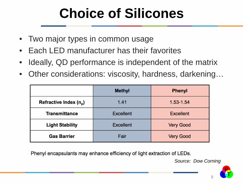
Choice of Silicones
8
• Two major types in common usage • Each LED manufacturer has their favorites • Ideally, QD performance is independent of the matrix • Other considerations: viscosity, hardness, darkening…
Source: Dow Corning
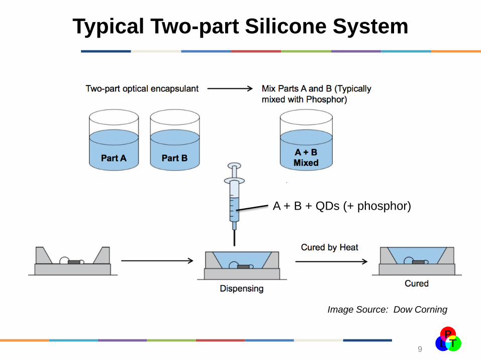
Typical Two-part Silicone System
9
Image Source: Dow Corning
A + B + QDs (+ phosphor)

QD Concentration Control
• Concentrations must be adjusted to accommodate various thickness requirements of the silicone film above the chip.
• Typical film thickness range 50-400 microns • The number-density of QDs above the chip determines
the conversion ratio • The mass per unit area or volume of the QDs required
is very different than that of phosphors and in total is 100’s of times less!
10

Quantum dots can be applied on-chip using most any application techniques and package types
1. Conformal or near-conformal coatings: most high power SSL packages use this approach – Includes COB packages and arrays – Customizable concentrations for various thicknesses – Highest fluxes and temps
• 100+ W/cm2, >125C
Spraying, printing, dispensing, etc:
1mm
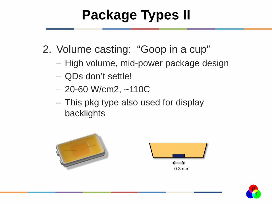
Package Types II
2. Volume casting: “Goop in a cup” – High volume, mid-power package design – QDs don’t settle! – 20-60 W/cm2, ~110C – This pkg type also used for display
backlights
0.3 mm
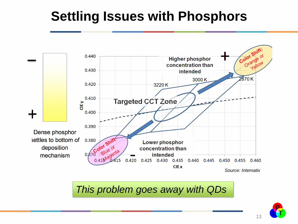
Settling Issues with Phosphors
13
Source: Intematix
This problem goes away with QDs

Package Types III
3. Remote Optic Lowest temperature and flux conditions
• <10W/cm2, <100C typically
10% or more higher efficiency claimed due to photon recycling
Most cost-sensitive, uncertain market acceptance
1mm
Molded or coated optic

Contributions to Heating
15
QD temperature is a function of: • Conductive heating from chip • Stokes loss • Non-radiative losses, quantum efficiency < 100% • Conductive/convective cooling from surfaces Net temperature rise for mid-power LEDs typically 10-20C over Tjn Measurable by thermal camera or monitoring wavelength shift of QD emission.
Tjn
TQDs
THS
Air
Heatsink
50-400 microns
Chip Heat
Stokes Loss Non-rad
Cond
Conv

Temperature Dependence: Low thermal quenching
Previous
New PLT Gen
Best Phosphors

PLT Results on Intensity Dependence
• For PLT materials, no cliff observed up to 50 W/cm, measured in silicone at ambient conditions
• Other tests have been made out to 1000 W/cm2
Conditions: room temp, 3mm laser spot at 450 nm on a red QD + silicone film, pulsed

On-chip QD requirements: Summary
Compatibility with silicones and mfg processes
Tolerant to high temperatures Tolerant to high pump intensity Maintenance of high quantum
efficiencies over life Ideally without a hermeticity
requirement
18
350 450 550 650 750Wavelength (nm)
Red QDs with green phosphor
Red and green phosphor
Actual operational data
Thank you!
Julian Osinski, Ph.D. Pacific Light Technologies [email protected]
Acknowledgements: Drs. Juanita Kurtin, Norbert Puetz, and the entire staff of Pacific Light Technologies
19