quantized constant envelope precoding with psk and qam...
TRANSCRIPT

1536-1276 (c) 2018 IEEE. Personal use is permitted, but republication/redistribution requires IEEE permission. See http://www.ieee.org/publications_standards/publications/rights/index.html for more information.
This article has been accepted for publication in a future issue of this journal, but has not been fully edited. Content may change prior to final publication. Citation information: DOI 10.1109/TWC.2018.2873386, IEEETransactions on Wireless Communications
1
Quantized Constant Envelope Precodingwith PSK and QAM Signaling
Hela Jedda, Student Member, IEEE,Amine Mezghani, Member, IEEE,, A. Lee Swindlehurst, Fellow, IEEE,, and Josef A. Nossek, Life Fellow, IEEE
Abstract—Coarsely quantized massive Multiple-InputMultiple-Output (MIMO) systems are gaining more interestdue to their power efficiency. We present a new precodingtechnique to mitigate the Multi-User Interference (MUI) andthe quantization distortions in a downlink Multi-User (MU)MIMO system with coarsely Quantized Constant Envelope(QCE) signals at the transmitter. The transmit signal vector isoptimized for every desired received vector taking into accounta relaxed version of the QCE constraint. The optimizationis based on maximizing the safety margin to the decisionthresholds of the receiver constellation modulation. Due to thelinear property of the objective function and the constraints, theoptimization problem is formulated as a linear programmingproblem. Simulation results show a significant gain in terms ofthe uncoded Bit Error Rate (BER) compared to the existingprecoding techniques.
Index Terms—Constant Envelope, Coarse Quantization, Con-structive Interference, Downlink Massive Multi-User MIMO,Precoding.
I. INTRODUCTION
THE next generation of mobile communication aims atincreasing 1000-fold the network capacity, 10-100-fold
the number of connected devices and decreasing 5-fold thelatency time and the power consumption compared to 4Gnetworks [1]. To achieve these challenging requirements, thefollowing technologies are the subject of current research:• massive Multiple-Input Multiple-Output (MIMO) sys-
tems, where the Base Stations (BSs) are equipped witha very large number of antennas (100 or more) that cansimultaneously serve many users [2]–[6],
• millimeter-Wave (mmW) communication, i.e. frequenciesranging between 30 GHz and 300 GHz, where the spec-trum is less crowded and greater bandwidth is available[7]–[9] and
H. Jedda is with the Associate Professorship of Signal Processing, TechnicalUniversity of Munich, 80290 Munich, Germany (e-mail: [email protected]).
A. Mezghani is with the Wireless Networking and CommunicationsGroup, University of Texas at Austin, Austin, TX 78712, USA (e-mail:[email protected]).
A. L. Swindlehurst is with the Center for Pervasive Communicationsand Computing, University of California, Irvine, CA 92697, USA (e-mail:[email protected]).
J. A. Nossek is with the Associate Professorship of Signal Processing,Technical University of Munich, 80290 Munich, Germany and also withthe Department of Teleinformatics Engineering, Federal University of Ceará,Fortaleza, Brazil (e-mail:[email protected]).
This work was supported by the National Science Foundation under GrantsECCS-1547155 and CCF-1703635, and by a Hans Fischer Senior Fellowshipfrom the Technische Universität München Institute for Advanced Study.
• smaller cells with ranges on the order of 10-200 m, i.e.pico- and femtocells.
First, massive MIMO systems lead to a drastic increasein the number of Radio Frequency (RF) chains at the BSand hence in the number of the wireless front-end hardwarecomponents. Second, mmW communication implies that thewireless front-end hardware components are operated at muchhigher frequencies. Third, reducing the cell size means thatthe number of cells per unit area is increased and thus resultsin a much more dense wireless network. Combining the threetechnologies means a dramatic increase in the number of RFhardware elements operating at very high frequencies per unitarea. Hence, the RF power consumption per unit area alarm-ingly increases. While the above technologies are foreseenas key technologies for future communication systems, theincrease in power consumption represents a crucial concern.
The most critical front-end elements in terms of powerconsumption, depending on whether the large number ofantennas is situated at the receiver or at the transmitter, are theAnalog-to-Digital Converters (ADCs) in the uplink scenario,and mainly the Power Amplifiers (PAs) and secondarily theDigital-to-Analog Converters (DACs) in the downlink sce-nario, which is the focus of this contribution. According to[10], [11], the PA is considered as the most power hungrydevice at the transmitter side. When the PA is run in thesaturation region, i.e. the highly non-linear region, high powerefficiency is achieved and hence less power is consumed [12].However, the saturation region implies strong non-linear signaldistortions. To omit the signal distortions, while keeping thePA operate in the saturation region, the input signals shouldfulfill the Constant Envelope (CE) property, which leads to aunit Peak-to-Average-Power Ratio (PAPR).
To this end, polar (phase-based) DACs at the transmitterare designed to convert the discrete-time and discrete-valuebase-band signals into continuous-time but discrete-value, i.e.discrete-phase, CE signals. The number of possible discretephases is determined by the resolution of the DAC. The largerthe resolution is, the more accurate the phase information atthe DAC’s output is, but the larger its power consumptionis [13]. To further reduce the hardware power consumption,the DAC’s resolution can be reduced. The use of coarselyquantized DACs is also beneficial in terms of reduced costand circuit area and can further simplify the surrounding RFcircuitry due to the relaxed linearity constraint, leading to veryefficient hardware implementations. In this way, the powerconsumption is reduced twofold: power efficient PAs due to the
1536-1276 (c) 2018 IEEE. Personal use is permitted, but republication/redistribution requires IEEE permission. See http://www.ieee.org/publications_standards/publications/rights/index.html for more information.
This article has been accepted for publication in a future issue of this journal, but has not been fully edited. Content may change prior to final publication. Citation information: DOI 10.1109/TWC.2018.2873386, IEEETransactions on Wireless Communications
2
CE signals and less power consuming polar DACs due to thelow resolution. However, this approach can lead to non-lineardistortions that degrade the system performance and have tobe mitigated by the precoder design in massive Multi-User(MU) MIMO downlink systems.
A. Related Works
Many works have addressed the precoding poblem in thecontext of CE transmit signals for massive MIMO systemssuch that [14]–[18], where the Multi-User Interference (MUI)is minimized subject to the CE constraint. Another work [19]opts for minimizing an upper bound of the Symbol Error Rate(SER) in the case of single-user Multiple-Input Single-Output(MISO) systems for two strategies: antenna-subset selection,where a subset of the antennas is selected for transmission,and unequal power allocation among the antennas, wherethe magnitude of the transmit signal at each antenna is keptconstant over a transmission period but the signal magnitudesat distinct transmit antennas are not necessarily equal. Theauthors of [20] jointly optimize the transmit CE precodingand the constellation in order to minimize the SER in aMISO multicast system. Recent works in [21] and [22] exploitthe constructive part of the MUI to design the CE precoder.The authors in [23] design a CE precoder to maximize theSignal-to-Leakage-plus-Noise Ratio (SLNR). In [24], a CEprecoder is jointly designed with the receive beamforming tominimize the SER for point-to-point MIMO systems, whileadopting antenna grouping for multi-stream transmission. Inthe above contributions, the DACs are assumed to have infiniteresolution.
The contribution in [25] is an early work that addressed theprecoding task with low resolution DACs at the transmitter.A linear Minimum Mean Squared Error (MMSE) precoderis designed, while quantization distortion is taken into ac-count. This precoding design is not given in the context ofcoarsely Quantized Constant Envelope (QCE) signals since theDACs are not polar but cartesian (in-phase- and quadrature).However, the extreme case of 1-bit DACs in [25] representsa special case of coarsely QCE signals. Many contributionsin the literature have studied this special case. They can becategorized in two groups: linear and non-linear precoders.In addition to the linear precoder in [25], we introduced in[26] another linear precoder, where the second-order statisticsof the 1-bit DAC signals are computed based on Price’stheorem [27]. Non-linear precoding techniques in this contextwere introduced in [28]–[33]. The non-linear methods canbe classified with respect to two design criteria: symbol-wiseMinimum Squared Error (MSE) and symbol-wise MaximumSafety Margin (MSM) exploiting the idea of constructiveinterference. In the context of symbol-wise MSE, the authorsin [29] presented a convex formulation of the problem andapplied it to higher-order modulations [30]. The problem for-mulation is based on semidefinite relaxation and squared `∞-norm relaxation. The same optimization problem was solvedmore efficiently in [32] and [34].
In the context of symbol-wise MSM in [28], we presenteda precoding technique based on a minimum Bit Error Rate
(BER) criterion and made use of the box norm (`∞) to relaxthe 1-bit constraint. Recently, the work in [33] proposed amethod to significantly improve linear precoding solutionsin conjunction with 1-bit quantization by properly perturbingthe linearly precoded signal for each given input signal tofavorably impact the probability of correct detection. In [31]the safety margin to the decision thresholds of the receivedPhase-Shift Keying (PSK) symbols is maximized subject toa relaxed 1-bit constraint using linear programming for flat-fading channels and extended in [35] for frequency-selectivechannels. The same optimization problem was solved by theBranch-and Bound algorithm in [36] for the special case of4-PSK.
To the best of our knowledge, the only works that haveconsidered the case of coarsely QCE transmit signals are [37]–[40]. In [37], we propose a symbol-wise MSE precoder basedon gradient-descent under a strict CE constraint or a relaxedpolygon constraint. In [38], the authors extend the methodin [29] to fit the context of QCE transmit signals. In [39],the authors use a greedy approach for the precoder designwhile using symbol-wise MSE as the design criterion. Thecontribution in [40] addresses the task of QCE precoding inthe context of using a single common PA and separate digitalphase shifters for the antenna front-ends. The optimizationproblem consists of designing the QCE precoder while min-imizing the MUI, and the idea of constructive interference,[41], [42], is not exploited as in our work. The concept of QCEprecoding and general constellations for flat-fading channelsis studied in this contribution and is extended partially tofrequency-selective channels in [35] and [43]. It is worthmentioning that the QCE precoding can be combined withappropriate pulse shaping strategies as in [44], [45] to ensurean efficient spectral confinement. In [46], it was shown that CEprecoding is still power efficient even when considering time-based processing. The same investigation can be conductedfor the case of QCE precoding. Here, we focus rather on thespatial design problem.
B. Main Contributions
The main contributions in this paper are summarized asfollows
1) We propose a method for QCE precoding in the contextof massive MIMO systems, where the transmit signalshave constant magnitude and phases drawn from adiscrete set. The precoder design is based on max-imizing the safety margin to the decision thresholdswhile exploiting the idea of constructive interference.The design criterion in [31] is extended to the coarseQCE case, where the QCE constraint is relaxed toa polygon constraint to ensure convexity. While theproposed design for PSK signaling is similar to the workin [22], we employ a relaxed polygon constraint ratherthan a relaxed unit circle constraint as in [22]. Sincethe polygon constraint can be expressed in terms oflinear convex inequalities, this allows us to solve theproblem using linear programming techniques, whichare significantly more efficient. The simulation results

1536-1276 (c) 2018 IEEE. Personal use is permitted, but republication/redistribution requires IEEE permission. See http://www.ieee.org/publications_standards/publications/rights/index.html for more information.
This article has been accepted for publication in a future issue of this journal, but has not been fully edited. Content may change prior to final publication. Citation information: DOI 10.1109/TWC.2018.2873386, IEEETransactions on Wireless Communications
3
related to the proposed method show a significant gainin terms of the uncoded BER compared to the methodin [22].
2) We extend the proposed QCE precoder to the caseof Quadrature Amplitude Modulation (QAM) signaling.The constructive interference idea has been applied pre-viously to QAM signals in [47]–[49] for different designcriteria and in other contexts, e.g for power minimiza-tion. In this contribution, we describe the constructiveinterference regions with modified mathematical expres-sions and a general QAM constellation that include thesafety margin to fit our design criterion. We solve theformulated problem within a pure linear programmingframework, one of the most studied problems in opti-mization. We also provided results where the receiverblindly estimates the QAM scaling factor. We extend theproposed QCE precoder to the case of QAM signaling.
C. Remainder and Notation
The remainder of this paper is organized as follows. InSection II, we present the system model. In Section III,the motivation behind formulating the precoding problemas a linear programming problem is explained. Sections IVand V present the corresponding optimization problems forPSK and QAM signals, respectively. The complexity of eachoptimization problem is discussed in Section VI. Simulationresults are introduced in VII. Finally, Section VIII summarizesthis work.
Notation: Bold lower case and upper case letters indicatevectors and matrices, non-bold letters express scalars. Theoperators (.)∗, (.)T and (.)H stand for complex conjugation,transposition and Hermitian transposition, respectively. Then × n identity (zero) matrix is denoted by In (0n,n). The ndimensional one (zero) vector is denoted by 1n (0n). Thevector em represents a zero-vector with 1 at the m-th position.Additionally, diag (a) denotes a diagonal matrix containingthe entries of the vector a. Every vector a of dimension Lis defined as a =
∑L`=1 a`el . The operator ⊗ denotes the
Kronecker product. The operator ≤ in the context of vectorinequalities applies element-wise to the vector entries.
II. SYSTEM MODEL
The system model shown in Fig.1 consists of a single-cellmassive MU-MIMO downlink scenario with coarsely QCEsignals at the transmitter. The BS is equipped with N antennasand serves M single-antenna users simultaneously, whereN � M . The input signal vector s contains the signals to betransmitted to each of the M users. Each user’s signal is drawnfrom the set S that represents either an S-PSK or S-QAMconstellation, where S denotes the number of constellationpoints. We assume that E[s] = 0M and E[ssH] = σ2
s IM . Thesignal vector s is precoded into the vector x ∈ XN prior to theDACs. The entries of x are amplitude-constrained and the setX is a convex set that can be described by linear inequalitiesas explained in Section III-A. The non-linear function P (•)is a symbol-wise precoder designed to reduce the distortionscaused by the coarse quantization and the MUI. The operator
QCE(•) models the non-linear behavior of the low-resolutionpolar DACs combined with the power allocation at the PAs as
t = QCE(x) =√
Ptx
Nej Qφ (arg(x)), (1)
where the total transmit power Ptx is allocated equally amongthe transmit antennas. The phase quantizer Qφ(•) is a sym-metric uniform real-valued quantizer. It is characterized by itsresolution q that defines the number of discrete output phases
Q = 2q . (2)
In other words, the 2π-phase range is divided into Q 2πQ -
rotationally symmetric sectors. The input signal that belongsto the k-th sector is quantized (mapped) to ej(2k−1) πQ . This canbe mathematically expressed as
Qφ(arg(xn)) =(⌊
arg(xn)2π/Q
⌋+
12
)2πQ, n = 1, · · · , N . (3)
Thus, the information after the CE quantizer lies only in thephase. Hence, the set T is defined as
T =
{√Ptx
Nexp
(j (2i − 1)
π
Q
): i = 1, · · · ,Q
}. (4)
Note that directly designing the mapping between s and twould lead to a discrete optimization problem that is NP-hard.Thus, we design in an intermediate step the vector x ∈ XN ,where X represents a convex relaxation of T as explained inSection III-A.
The signal t is transmitted through a flat-fading channelthat is modeled by the matrix H of elements hmn,m =
1, · · · , M, n = 1, · · · , N . At the M receive antennas, AdditiveWhite Gaussian Noise (AWGN), which is denoted by thevector η ∼ CNC
(0M,Cη = IM
), perturbs the received signals
r = Ht + η. (5)
Since the precoder is implemented symbol-by-symbol, jointprocessing at the receiver would require not only knowledgeof the channel but also the desired received signals themselves,which are unknown at the receiver. Therefore, the precoder isdesigned such that, without any noise, the received signalswould lie in their intended decision regions and no jointreceive processing is necessary. Additionally, coherent datatransmission with multiple BS antennas leads to an antennagain, which depends on the channel realization. Hence, theprecoder design leads in the best case scenario to the fact that,the entries of the received signal vector r do not belong to thenominal decision regions of S but to a scaled version of them.Therefore, rescaling the received signal at each receive antennais required to ensure that the received signal belongs to thenominal decision region. The rescaling operation is modeledby the diagonal real-valued matrix G, as follows
u = G (Ht + η) , (6)
where
G =M∑m=1
gmemeTm, (7)

1536-1276 (c) 2018 IEEE. Personal use is permitted, but republication/redistribution requires IEEE permission. See http://www.ieee.org/publications_standards/publications/rights/index.html for more information.
This article has been accepted for publication in a future issue of this journal, but has not been fully edited. Content may change prior to final publication. Citation information: DOI 10.1109/TWC.2018.2873386, IEEETransactions on Wireless Communications
4
P (•) QCE (•) H +
η
G D (•)sSM
xXN
tTN
y
CM
rCM
uCM
sSM
Fig. 1: Downlink MU-MIMO system model.
with gm > 0, m = 0, · · · , M . The coefficients gm are blindlyestimated at the receiver over a block of received symbolsas explained in Section V-F. Note that no receive processingG is required if S represents the PSK constellation. Finally,based on the decision regions to which the entries of the signalu belong, the decision operation D(•) produces the detectedsymbols s at the users
s = D (G (Ht + η)) . (8)
III. PRECODING TASK
In this work, we make use of the idea of constructive inter-ference optimization [41], [42]. When the downlink channeland all users’ data are known at the transmitter, instantaneousconstructive MUI can be exploited to move the receivedsignals further from the decision thresholds [42]. In contrast tothis, conventional precoding methods (MMSE, Zero-forcing)aim at minimizing the total MUI such that the receivedsignals lie as close as possible to the nominal constellationpoints. Constructive interference optimization exploits thelarger symbol decision regions and thus leads to a more relaxedoptimization.
For every given input signal s and for each channel realiza-tion H, the precoding task is to find
x = P (s,H) . (9)
The task consists of designing the transmit vector x such thats = s holds true with high probability to reduce the detectionerror probability. The symbol-wise precoder aims to mitigateall sources of distortion:• the quantization distortions• the channel distortions, and• the AWGN.
Our goal is to develop a problem formulation that jointlyminimizes all three distortion sources.
A. Mitigation of the Quantization Distortions
First, it is obvious that the quantization distortions can beomitted if we design the precoded vector x such that
x ∈ TN, (10)
i.e. X = T. This would ensure that the quantizer QCE(•)
produces no distortion, and we would have an undistortedtransmit signal t = x. However, the QCE constraint in (10)would lead to a discrete optimization problem due to thediscrete nature of the set T. To avoid this problem, we relax thediscrete set T to the convex set X that represents the polygonbuilt by the Q scaled PSK points of the set T. Thus, theQCE constraint is relaxed to a convex constraint that we call
<
j=
Fig. 2: Illustration of the relaxed polygon constraint for Q=8.
the relaxed polygon constraint. Fig. 2 illustrates the relaxedpolygon constraint for the case of Q = 8. Instead of designingx ∈ TN to completely eliminate the quantization distortions,we design x ∈ XN to minimize them.
The set X can be mathematically described by a set of linearinequalities. For q-bit polar DACs, i.e., where the transmitteddata are constrained to be Q scaled PSK symbols, the polygoncan be constructed by the intersection of Q/4 squares that havean angular shift of 2π/Q. To this end, we define the rotationmatrix Ri of angle βi =
2πQ (i − 1) as
Ri =
[cos βi sin βi− sin βi cos βi
]⊗ IN, i = 1, ...,Q/4. (11)
The system of inequalities that considers the feasible set,i.e. the relaxed polygon constraint, and hence relaxes theconstraint in (10) is given by[
RT1 −RT
1 · · · RTQ4−RT
Q4
]Tx ≤
√Ptx
Ncos
(π
Q
)1NQ, (12)
where x =[<{x}T ={x}T
]T. Since R1 = I2N , the first 4Ninequalities in (12) define the bounds for x. Hence, the relaxedpolygon constraint, i.e. x ∈ XN , is equivalent to
−
√Ptx
2Ncos
(π
Q
)12N ≤ x ≤
√Ptx
Ncos
(π
Q
)12N,
and[RT
2 −RT2 · · · RT
Q4−RT
Q4
]T︸ ︷︷ ︸=E
x ≤√
Ptx
Ncos
(π
Q
)1N (Q−4).
(13)
This reformulation leads to significant computational savingssince the final optimization problem will be written as a linearprogram with bounded variables. As discussed in Section VI,it is beneficial in terms of computational complexity to havefewer inequalities.
1536-1276 (c) 2018 IEEE. Personal use is permitted, but republication/redistribution requires IEEE permission. See http://www.ieee.org/publications_standards/publications/rights/index.html for more information.
This article has been accepted for publication in a future issue of this journal, but has not been fully edited. Content may change prior to final publication. Citation information: DOI 10.1109/TWC.2018.2873386, IEEETransactions on Wireless Communications
5
<
j=
δ
(a) 8-PSK.
<
j=
δ
(b) 16-QAM.
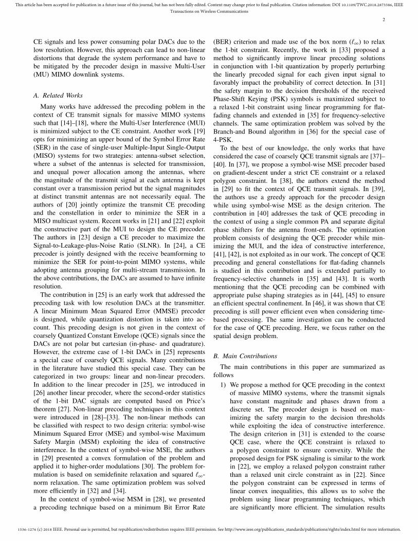
Fig. 3: Decision and symbol regions (in red).
B. Counteracting the Channel Distortions and the Noise
Second, to minimize the channel distortions and the noise,we look deeper into the properties of the constellations. Asillustrated in Fig. 3a and Fig. 3b, each constellation is definedby thresholds that separate the distinct decision regions of theconstellation points. In total, we have as many contiguousdecision regions as constellation points. Each constellationsymbol lies within a Symbol Region (SR) that is a downscaledversion of the decision region. In contrast to the decisionregion, the SR has a safety margin denoted by δ that separatesit from the decision thresholds. When each entry of thenoiseless received signal vector y belongs to the correct SRand thus the correct decision region, the channel distortionsare mitigated. Additionally, the safety margin δ has to belarge enough such that, when perturbed by the additive noise,the received signals do not jump to unintended neighboringdecision regions.
C. General Problem Formulation
In summary, the problem formulation has to take intoaccount the relaxed QCE constraint in (13), the SR for eachreceived signal and maximizing the safety margin. Thus, theoptimization problem for the symbol-wise precoder, which wecall the MSM precoder, can be written in general as follows
maxxδ (14)
s.t. y′m ∈ SRm, ∀m (15)
and x ∈ XN, (16)
where
y′ = Hx (17)
represents the relaxation of y due to the relaxation of (10) to(13). Exact expressions for the safety margin δ and the SRsas a function of x are provided in Section IV and Section Vfor PSK and QAM signaling, respectively.
IV. PROBLEM FORMULATION FOR PSK SIGNALING
A. Symbol Region for PSK Signals
In this section, we assume that the input signals sm, m =1, · · · , M , belong to the S-PSK constellation. The set S in thiscase is defined as
S := {exp (j (2i − 1) θ) : i = 1, · · · , S} , where θ =π
S. (18)
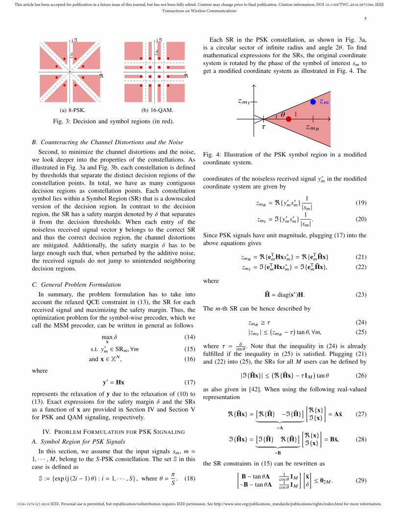
Each SR in the PSK constellation, as shown in Fig. 3a,is a circular sector of infinite radius and angle 2θ. To findmathematical expressions for the SRs, the original coordinatesystem is rotated by the phase of the symbol of interest sm toget a modified coordinate system as illustrated in Fig. 4. The
1
zm
zmR
zmI
τ
θ
Fig. 4: Illustration of the PSK symbol region in a modifiedcoordinate system.
coordinates of the noiseless received signal y′m in the modifiedcoordinate system are given by
zmR = <{y′ms∗m}
1|sm |
(19)
zmI = ={y′ms∗m}
1|sm |
. (20)
Since PSK signals have unit magnitude, plugging (17) into theabove equations gives
zmR = <{eTmHxs∗m} = <{eT
mHx} (21)
zmI = ={eTmHxs∗m} = ={eT
mHx}, (22)
where
H = diag(s∗)H. (23)
The m-th SR can be hence described by
zmR ≥ τ (24)|zmI | ≤
(zmR − τ
)tan θ, ∀m, (25)
where τ = δsin θ . Note that the inequality in (24) is already
fulfilled if the inequality in (25) is satisfied. Plugging (21)and (22) into (25), the SRs for all M users can be defined by
|={Hx}| ≤(<{Hx} − τ1M
)tan θ (26)
as also given in [42]. When using the following real-valuedrepresentation
<{Hx} =[<{H} −={H}
]︸ ︷︷ ︸=A
[<{x}={x}
]= Ax (27)
={Hx} =[={H} <{H}
]︸ ︷︷ ︸=B
[<{x}={x}
]= Bx, (28)
the SR constraints in (15) can be rewritten as[B − tan θA 1
cos θ 1M
−B − tan θA 1cos θ 1M
] [xδ
]≤ 02M . (29)
1536-1276 (c) 2018 IEEE. Personal use is permitted, but republication/redistribution requires IEEE permission. See http://www.ieee.org/publications_standards/publications/rights/index.html for more information.
This article has been accepted for publication in a future issue of this journal, but has not been fully edited. Content may change prior to final publication. Citation information: DOI 10.1109/TWC.2018.2873386, IEEETransactions on Wireless Communications
6
B. Safety Margin for PSK Signals
The safety margin δ in (14) can be expressed for the PSKcase as
δ = minm(sin(θ)zR − cos(θ) |zI |) , (30)
where the operator |•| is applied element-wise to the entries ofzI. Note that an equivalent objective function was introducedin [22] in the context of continuous-phase CE precoding forPSK signaling. In [22], the strict CE constraint is relaxed tothe convex unit circle, whereas in our work the QCE constraintis relaxed to the linear polygon constraint. Consequently, dueto the linear objective function and the linear constraints, ouroptimization problem can be formulated as a linear program-ming problem unlike [22].
C. Optimization Problem
Finally, the optimization problem for the symbol-wise pre-coder with PSK signaling is obtained by combining (14), (29)and (13) and is expressed for the case of Ptx = N as
maxx,δ
[0T
2N 1] [
xδ
]s.t.
B − tan θA 1
cos θ 1M
−B − tan θA 1cos θ 1M
E 0N (Q−4)
[xδ
]≤
[02M
cos(πQ
)1N (Q−4)
],
and
[− cos
(πQ
)12N
0
]≤
[xδ
]≤
[cos
(πQ
)12N
∞
]. (31)
The resulting optimization is a linear programming problemfor which there exist very efficient solution methods [50].In order to solve the problem for different Ptx values, it issufficient to scale the solution of (31) by Ptx
N due to the linearityof the optimization.
When the optimization terminates, the optimal signal x ∈XN is found. The signal t that goes through the channel isobtained as described in (1). In other words, each entry in xgets mapped to the corresponding CE point depending on thecircular sector in which it lies.
D. Interpretation of the Safety Margin δ for PSK Signals
The safety margin δ is a parameter that affects the receiverSignal-to-Noise Ratio (SNR) and the SER. These relationshipswill be given for the relaxed problem; that is the quantizationis omitted and we consider the relaxed received signal y′.The receiver SNR at the m-th user is given by
SNRm =E
[��y′m��2]σ2n
= E[��y′m��2] , (32)
since we assume unit-variance AWGN. The expected value canbe computed by averaging over Ns transmit signals. Hence, weget
SNRm ≥1
Ns
Ns∑i=1
(δ(i)
sin θ
)2
. (33)
Thus, we can conclude that maximizing the safety margin δleads in turn to maximizing the lower bound of the receive
SNR at each user.Moreover, it can be proven that the SER at the m-th user isupper bounded by
SERm ≤ 1 −1
Ns
Ns∑i=1
∫ ∞
− δ(i)
sin θ
erf(δ(i)
cos(θ)+ γ tan(θ)
)1√π
e−γ2
dγ,
(34)
which explains why maximizing δ minimizes the SER.
V. PROBLEM FORMULATION FOR QAM SIGNALING
A. The Need for an Additional Degree of Freedom α
In this section, we assume that the input signals sm,m = 1, · · · , M , belong to the S-QAM constellation, where Sis assumed to be a power of 4. The QAM symbols are drawnfrom the set S defined as
S :={± (2i − 1) ± j (2i − 1) : i = 1, · · · , log4(S)
}. (35)
As explained in Section III, the safety margin δ has to bemaximized such that the entries of the noiseless received signaly′ belong to the intended SRs. The SRs in turn are determinedby the constellation set S and the safety margin δ. Hence, thesafety margin δ must satisfy
δ ≤ 1. (36)
Independently of the available transmit power, the entries of y′cannot have a distance to the decision thresholds larger than 1.Hence, the available transmit power cannot be exploited to thefullest, which is a limitation of the problem formulation.
Thanks to the receive processing G, we can introduce anadditional degree of freedom α such that the entries of thereceived signal y′ do not have to belong to the SRs of the setS but rather to a scaled version of them. That is, the QAMconstellation at each receiver is scaled by α, and thus theconstraint in (36) is replaced by
δ ≤ α, (37)
where α has to be jointly optimized with δ. Note that maximiz-ing δ leads in turn to maximizing α, which leads to a maximalexploitation of the available transmit power. Thus, the entriesof the signal vector x will get closer to the polygon corners,which decreases the variations between t and x.
The factor α denotes the expansion or shrinkage factorof the constellation at the receiver side depending on theavailable transmit power Ptx. As explained in Section III, theoptimization problem is formulated for the specific case, i.e.Ptx = N .
B. Scaled Symbol Region for QAM Signals
In order to describe the SRs for QAM signaling in the samecoordinate system for all possible QAM constellation points,we define a new coordinate system, that is a shifted and rotatedversion of the original coordinate system while considering α.

1536-1276 (c) 2018 IEEE. Personal use is permitted, but republication/redistribution requires IEEE permission. See http://www.ieee.org/publications_standards/publications/rights/index.html for more information.
This article has been accepted for publication in a future issue of this journal, but has not been fully edited. Content may change prior to final publication. Citation information: DOI 10.1109/TWC.2018.2873386, IEEETransactions on Wireless Communications
7
<(om )
j=(om )
δ
om
zmR
zmI
sm(om)
y′m(om)
α
α
αξ1m
αξ2m
Fig. 5: Illustration of the QAM receiver symbol region for<{sm} > 0 and = {sm} > 0 in the shifted coordinate system(in black) and in the shifted and rotated coordinate system (ingray): ξ1/2m
∈ {2,∞}.
First, the QAM coordinate system at each receiver is shiftedby om
om = α
((< {sm} − sgn (< {sm}))
+ j (= {sm} − sgn (= {sm}))
). (38)
We get the following expressions for the received and thedesired signal in the new coordinate system depicted in Fig. 5
ym′(om)= y′m − om
= eTmHx − om (39)
sm(om) = αsm − om= α (sgn (< {sm}) + j sgn (= {sm})) . (40)
Second, the intermediate coordinate system is rotated by thephase of the symbol of interest sm(om). So the received signaly′m has the following coordinates in the shifted and rotatedcoordinate system
zmR =<
{ym′(om)
sm∗(om)
}|sm(om) |
, (41)
and
zmI ==
{ym′(om)
sm∗(om)
}|sm(om) |
. (42)
We get
ym′(om)
sm∗(om)
|sm(om) |= eT
m
(Hx − αc
), (43)
where
H =1√
2diag (sgn (< {s}) − j sgn (= {s}))H, (44)
and
c =1√
2αdiag (sgn (< [s]) − j sgn (= [s])) o. (45)
Note that cm, ∀m, does not depend on α as can be concludedfrom (38) and (45). Plugging (43) into (41) and (42), we get
zmR = eTmVx − α<{cm} (46)
zmI = eTmWx − α= {cm} , (47)
where
V =[<{H} −={H}
](48)
W =[={H} <{H}
]. (49)
The m-th SR, as shown in Fig. 5, can hence be described by
zmR ≥√
2δ (50)
zmR ≤
√(αξ1m − δ
)2+
(αξ2m − δ
)2 (51)
|zmI | ≤
(zmR −
√2δ
)(52)
zmI ≤ −zmR +√
2(αξ2m − δ
)(53)
zmI ≥ zmR −√
2(αξ1m − δ
). (54)
Note that ξ1m and ξ2m ∈ {2,∞} depending on which constel-lation point the symbol of interest sm corresponds to. If sm isone of the outer constellation points, then at least one of ξ1m
or ξ2m must be equal to ∞. Since (50) and (51) are inherentlyfulfilled by (52), (53) and (54), the constraint of the SRs in(15) can be rewritten as
W − V 1M <{c} − = {c}−W − V 1M <{c} + = {c}W + V 1M −< {c} − = {c} −
√2ξ2
−W + V 1M −< {c} + = {c} −√
2ξ1
x√
2δα
≤ 04M . (55)
C. Safety Margin δ for QAM SignalsFor the QAM case, the safety margin δ in (14) can be
expressed as
δ = minm
min( 1√
2(zR − |zI |) ,αξ1 −
1√
2(zR − zI ) ,
αξ2 −1√
2(zR + zI )
), (56)
where the operator |•| is applied element-wise to the entriesof zI .
D. Optimization ProblemWe are interested in maximizing the safety margin as
presented in (14). In contrast to the PSK case, there is aconstraint on δ in the QAM case, stated in (37), which isinherently fulfilled by (55). Combining (14) with the SRconstraint in (55) and the relaxed polygon constraint in (13),we get a linear programming problem for the design of thesymbol-wise precoder for QAM signaling. The optimizationproblem for the case of Ptx = N is given in (57), In order tosolve the optimization problem for different Ptx values, it issufficient to scale the optimal solution of (31) by Ptx
N due tothe linearity of the optimization problem.
Again the optimized vector x ∈ XN goes through thequantizer, as stated in (1), to obtain the transmit vector t.

1536-1276 (c) 2018 IEEE. Personal use is permitted, but republication/redistribution requires IEEE permission. See http://www.ieee.org/publications_standards/publications/rights/index.html for more information.
This article has been accepted for publication in a future issue of this journal, but has not been fully edited. Content may change prior to final publication. Citation information: DOI 10.1109/TWC.2018.2873386, IEEETransactions on Wireless Communications
8
maxx,δ,α
[0T
2N 1 0]
xδα
s.t.
W − V
√21M <{c} − = {c}
−W − V√
21M <{c} + = {c}W + V
√21M −< {c} − = {c} −
√2ξ2
−W + V√
21M −< {c} + = {c} −√
2ξ1E 0N (Q−4) 0N (Q−4)
xδα
≤[
04M
cos(πQ
)1N (Q−4)
]
and
− cos
(πQ
)12N
00
≤xδα
≤cos
(πQ
)12N
∞
∞
. (57)
E. Interpretation of the Safety Margin δ for QAM Signals
Again we consider the relaxed problem; that is the quan-tization is omitted and we consider the received signal y′instead of y. Hence, the receive SNR at the m-th user canbe approximated by
SNRm ≈1
Ns
Ns∑i=1(α(i))2σ2
s . (58)
Since δ ≤ α, we get
SNRm ≥1
Ns
Ns∑i=1(δ(i))2σ2
s . (59)
Thus, maximizing δ results in maximizing the lower bound ofthe receiver SNR.Moreover, it can be proven that the SER at the m-th user isupper bounded by
SERm≤1+1
Ns
Ns∑i=1
∫ 2√
2α(i)−z(i)m,R
−z(i)m,R
(1−2erf
(√2δ(i) + γ
)) 1√π
e−γ2dγ.
(60)
Since erf is a monotonically increasing function, larger valuesof δ lead to minimize the upper bound of the SER.
F. Receive Processing
The variables of the optimization problem are the transmitvector x, the safety margin δ and the expansion factor α.The latter determines the receive processing G. Note thatthe optimal value of α is determined on a symbol-by-symbolbasis, and its value cannot be communicated to the receiver.However, due to the large number of users combined withthe massive MIMO assumption, the fluctuations of α acrossthe symbols are small as explained in Section V-H. Thereforean exact value of α is not required at the receiver. Onlythe positions of the decision thresholds are needed to rescalethe receiver constellation points to the nominal constellationpoints, and these only depend on the mean value of α. Anestimate of the mean of α can easily be computed by averagingover a block of received signals.
After multiplication with the receiver coefficient gm, thescaled received signal is
um = gmrm = gm eTm Ht + gmηm = sm + η′m, (61)
where η′m denotes the deviation of um from the nominalpoint sm due to the AWGN ηm, the SR constraint and the
quantization applied on the relaxed optimized vector x. Then,we can write
|<{rm}|+ |Im{rm}| = g−1m
(|<{sm+η′m}|+|={sm+η
′m}|
)(62)
≈ g−1m (|<{sm}| + |={sm}|)
+ g−1m
(<{η′m} + ={η
′m}
), (63)
where the approximation is very accurate when the receiverSignal-to-Interference-Noise Ratio (SINR) is much largerthan 1, which is the case for massive MIMO systems. Havingzero-mean noise plus interference η′m, we get
E[|<{rm}| + |={rm}|] ≈ g−1m E[|<{sm}| + |={sm}|]
≈ g−1m
√S, (64)
when using the definition of the QAM constellation in (35).Based on (64), we propose a blind estimation method toobtain the scaling factor gm for each user prior to the decisionoperation; that is
gm = T ·
√S∑T
t=1 |<{rm[t]}| + |={rm[t]}|, (65)
where T is the length the received sequence. The method doesnot require any feedback or training from the BS nor anyknowledge of the noise plus interference power at the userterminal.
G. Symbol-wise Processing vs. Block-wise Processing
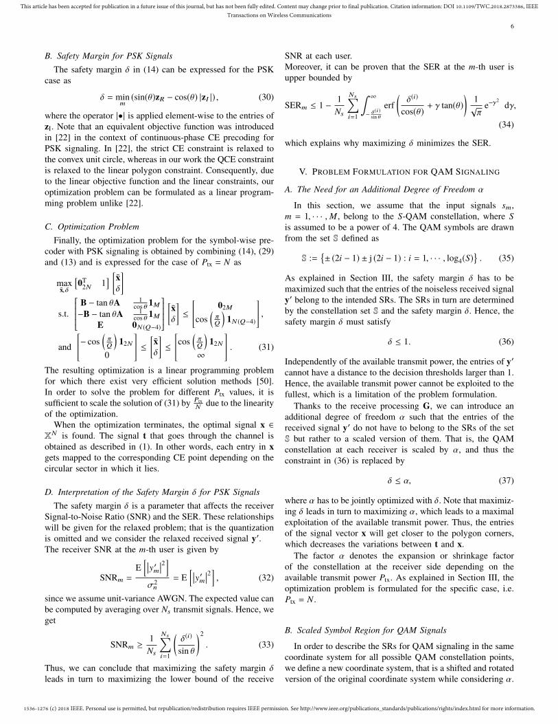
One might ask why we opt for symbol-wise processingand not block-wise processing. The factor α cannot be com-municated to the receiver and hence has to be estimated.The estimation is based on averaging over a block of Treceived signals. Thus, one expects that the design of α at thetransmitter has to be computed for the same block length, i.e.B = T . However, fixing α for a certain block length B meansthat B vectors x have to be designed jointly with a single factorα instead of having a distinct factor α for every vector x. Addi-tionally, the joint optimization of B vectors results in a higher-dimensional linear programming problem, where the numberof inequalities is increased by a factor of B. Hence, block-wiseprocessing not only increases the computational complexityof the problem as can be deduced from Section VI but alsoreduces the degrees of freedom of the optimization problem atthe transmitter. This leads to the entries of the vector x movingfarther from the polygon corners, thus increasing the quanti-zation distortions. This effect is illustrated in Fig. 6, where the
1536-1276 (c) 2018 IEEE. Personal use is permitted, but republication/redistribution requires IEEE permission. See http://www.ieee.org/publications_standards/publications/rights/index.html for more information.
This article has been accepted for publication in a future issue of this journal, but has not been fully edited. Content may change prior to final publication. Citation information: DOI 10.1109/TWC.2018.2873386, IEEETransactions on Wireless Communications
9
B = 1
B = 4
-10
10
-10
10
-2
2
-10
10
-10
10
-2
2
eTmHx eT
mHt 1αeT
mHt
Fig. 6: The noiseless received symbols for an arbitrary user mand an arbitrary i.i.d. channel realization with N = 64, M = 8and Q = 4.
entries of eTmHx, eT
mHt and 1αeT
mHt of an arbitrary user m areobtained by transmitting 1024 16-QAM signal vectors throughan independent and identically distributed (i.i.d.) channel ofcoefficients hmn ∼ CNC(0, 1), n = 1, · · · , N, m = 1, · · · , M ,where N = 64, M = 8 and Q = 4. The optimizationis computed for both symbol-wise processing, i.e. B = 1,and block-wise processing with B = 4. As can be deducedfrom the plots, block-wise processing leads to a larger safetymargin with the relaxed vector x. However, after applying thequantization this gain is lost and the symbol-wise processingis more robust against the quantization operation. This canbe further explained by the results in Table I, which showsE
[‖t,x‖1
N
], the percentange of entries of x that are distorted
due to the quantization and the MSE between t and x. Wesee that increasing B significantly increases the quantizationdistortion. Therefore, symbol-wise processing is chosen in
B = 1 B = 4E
[‖t,x‖1N
]0.2176 0.4432
E[‖t − x‖22
]2.5458 12.6429
TABLE I: Quantization distortion vs. B.
this contribution, i.e, an optimal value of α is designed foreach vector x.
H. One Joint α vs. M Distinct α’s for M Users
Symbol-wise transmit processing followed by block-wisereceive processing is reliable only if the obtained values ofα, i.e. α(i), i = 1, · · · ,T , do not vary much from one vectorx(i) to another. Otherwise, estimating the mean value of αat the receiver would not be sufficient for correct detection.To understand this behavior, we introduce the nominal safety
margin δnom, which is obtained after the receive filter G in thenoise-free case. It can be proven that
δnom ≥
miniδ(i)∑T
i=1 α(i)/T
− 2∆α, (66)
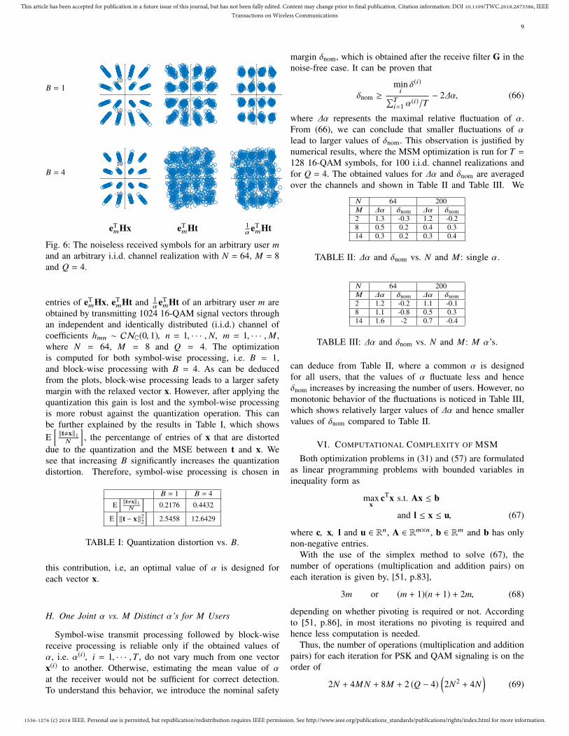
where ∆α represents the maximal relative fluctuation of α.From (66), we can conclude that smaller fluctuations of αlead to larger values of δnom. This observation is justified bynumerical results, where the MSM optimization is run for T =128 16-QAM symbols, for 100 i.i.d. channel realizations andfor Q = 4. The obtained values for ∆α and δnom are averagedover the channels and shown in Table II and Table III. We
N 64 200M ∆α δnom ∆α δnom2 1.3 -0.3 1.2 -0.28 0.5 0.2 0.4 0.314 0.3 0.2 0.3 0.4
TABLE II: ∆α and δnom vs. N and M: single α.
N 64 200M ∆α δnom ∆α δnom2 1.2 -0.2 1.1 -0.18 1.1 -0.8 0.5 0.314 1.6 -2 0.7 -0.4
TABLE III: ∆α and δnom vs. N and M: M α’s.
can deduce from Table II, where a common α is designedfor all users, that the values of α fluctuate less and henceδnom increases by increasing the number of users. However, nomonotonic behavior of the fluctuations is noticed in Table III,which shows relatively larger values of ∆α and hence smallervalues of δnom compared to Table II.
VI. COMPUTATIONAL COMPLEXITY OF MSM
Both optimization problems in (31) and (57) are formulatedas linear programming problems with bounded variables ininequality form as
maxx
cTx s.t. Ax ≤ b
and l ≤ x ≤ u, (67)
where c, x, l and u ∈ Rn, A ∈ Rm×n, b ∈ Rm and b has onlynon-negative entries.
With the use of the simplex method to solve (67), thenumber of operations (multiplication and addition pairs) oneach iteration is given by, [51, p.83],
3m or (m + 1)(n + 1) + 2m, (68)
depending on whether pivoting is required or not. Accordingto [51, p.86], in most iterations no pivoting is required andhence less computation is needed.
Thus, the number of operations (multiplication and additionpairs) for each iteration for PSK and QAM signaling is on theorder of
2N + 4MN + 8M + 2 (Q − 4)(2N2 + 4N
)(69)

1536-1276 (c) 2018 IEEE. Personal use is permitted, but republication/redistribution requires IEEE permission. See http://www.ieee.org/publications_standards/publications/rights/index.html for more information.
This article has been accepted for publication in a future issue of this journal, but has not been fully edited. Content may change prior to final publication. Citation information: DOI 10.1109/TWC.2018.2873386, IEEETransactions on Wireless Communications
10
−6 −4 −2 0 2 4 6 8 10 1210−4
10−3
10−2
10−1
100
Ptx (dB)
Unc
oded
BE
R
MSMSQUID [29]QWF [25]CE [37]CVX-CIO [22]WF-CEThe ideal WF [52]
Fig. 7: Uncoded BER performance for a MU-MIMO systemwith N = 64 and M = 8 for different precoding designs and4-PSK signaling.
and
2N + 8MN + 20M + 3 + (Q − 4)(2N2 + 5N
), (70)
respectively. For the special case of 1-bit quantization, i.e.Q = 4, the complexity is linear in N and M . However, thecomplexity is quadratic in N for Q > 4. Note that the sparsityof E can be exploited by deploying the revised simplex methodto reduce the number of required operations [51, p.89].
VII. SIMULATION RESULTS
For the simulations, we assume a BS with N = 64 antennasserving M = 8 single-antenna users. The channel H is com-posed of i.i.d. Gaussian random variables with zero-mean andunit variance. The numerical results are obtained with MonteCarlo simulations of 100 independent channel realizations.The additive noise is also i.i.d. with variance one at eachantenna. The performance metric is the uncoded BER averagedover the single-antenna users. For the blind estimation of thecoefficients gm we use a block length of T = 128.
In the first simulation set, depicted in Fig. 7, we assume fullChannel State Information (CSI), choose 4-PSK modulationand compare the uncoded BER as a function of the transmitpower Ptx for the following precoders:• The proposed MSM method with Q = 4.• The SQUID precoder presented in [29] with Q = 4,
where the precoder design criterion is the symbol-wiseMSE between u and s under a quantization constraint.The latter is equivalent to the QCE constraint for thespecial case Q = 4. The SQUID precoder is a semi-definite relaxation based algorithm.
• The quantized Wiener Filter (WF) precoder denoted by"QWF" from [25] with Q = 4. This precoder design isbased on linearizing the quantizer and considering theresulting quantization noise as additive Gaussian noise.
• The CE precoder presented in [37] denoted by "CE [37]",with Q = ∞, where the symbol-wise MSE between yand a scaled version of s is minimized under the CEconstraint. The scaling factor that is applied to s is jointlyoptimized.
−10 0 10 2010−4
10−3
10−2
10−1
100
Ptx (dB)
Unc
oded
BE
R
QPSK8-PSK16-PSK16-QAM64-QAM
(a) Q = 4
−10 0 10 2010−4
10−3
10−2
10−1
100
Ptx (dB)
Unc
oded
BE
R
QPSK8-PSK16-PSK16-QAM64-QAM
(b) Q = 8
Fig. 8: Uncoded BER performance of MSM for a MU-MIMOsystem with N = 64 and M = 8 for different modulationschemes: MSM (solid lines), the ideal WF (dashed lines).
• The CE precoder from [22] denoted by CVX-CIO thataims at maximizing the constructive interference underthe CE constraint.
• The WF precoder followed by the CE quantizer with Q =∞ denoted by "WF-CE", and
• The WF precoder in the ideal case denoted by "The idealWF" from [52], where neither quantization nor the CEconstraint is applied to the transmit signal.
It can be seen that the CE constraint leads to a loss of almost2 dB at a BER of 10−2 compared to the ideal WF and a lossof less than 1.5 dB when using the unquantized symbol-wiseprecoders proposed in [37] and in [22]. The 1-bit quantization,which represents the QCE case of Q = 4, leads to more lossesthat depend on the precoder design. With the use of the linearprecoder QWF a loss of more than 4 dB at a BER of 10−2 isnoticed. However, the non-linear precoders MSM and SQUIDimprove the performance drastically and show a loss of slightlymore than 2 dB compared to the ideal case at the cost ofhigher computational complexity. Nevertheless, the proposedMSM method is more efficient than SQUID as it is based ona purely linear programming formulation.
In the second simulation set, depicted in Fig. 8a and Fig. 8b,the uncoded BER is plotted as a function of the transmit powerPtx using the MSM precoder for different modulation schemesand two different values of Q: Q = 4 and Q = 8. Highervalues of Q are omitted since the obtained results do not differmuch from the case of Q = 8. In addition, it is beneficial interms of computational complexity and power consumptionto keep Q as small as possible. As expected, the higher thenumber of symbols in the modulation scheme, the higher theBER for a given Ptx value. However, the increase of the DACresolution q and thus the resulting increase in Q leads to aperformance improvement, which depends on the modulationscheme. Interestingly, the 16-QAM results outperform the 16-PSK results with a gain of almost 4 dB at a BER of 10−2 forthe case of Q = 4, whereas in the case of Q = 8 the gainreduces to 3 dB and the 16-PSK modulation outperforms the16-QAM for transmit power values larger than 15 dB.

1536-1276 (c) 2018 IEEE. Personal use is permitted, but republication/redistribution requires IEEE permission. See http://www.ieee.org/publications_standards/publications/rights/index.html for more information.
This article has been accepted for publication in a future issue of this journal, but has not been fully edited. Content may change prior to final publication. Citation information: DOI 10.1109/TWC.2018.2873386, IEEETransactions on Wireless Communications
11
−10 0 10 2010−4
10−3
10−2
10−1
100
QPSK8-PSK
16-PSK
Ptx (dB)
Unc
oded
BE
R
MSMCVX-CIOCVX-CIO-noCE
(a) Q = 4
−10 0 10 2010−4
10−3
10−2
10−1
100
QPSK 8-PSK
16-PSK
Ptx (dB)
Unc
oded
BE
R
MSMCVX-CIOCVX-CIO-noCE
(b) Q = 8
Fig. 9: Comparison of the uncoded BER performance betweenMSM, CVX-CIO from [22] and CVX-CIO-noCE for a MU-MIMO system with N = 64 and M = 8.
Since the optimization problem in [22] has some similaritieswith our proposed MSM, we compare the uncoded BER per-formance for both designs in Fig. 9. In our simulation, we passthe entries of x obtained by the CVX-CIO method through theCE quantizer to get QCE signals. Additionally, we introducethe method denoted by CVX-CIO-noCE that is the same asCVX-CIO with an instantaneous power constraint instead ofthe CE constraint. As can be seen from the results, CVX-CIO and CVX-CIO-noCE do not perform optimally underthe constraint of QCE transmit signals. However, the losscompared to MSM reduces when the quantization resolutionincreases. The method introduced in [21], which is basedon the Riemannian Conjugate Gradient (RGC) approach forCE precoding with the use of the constructive interferenceprinciple, shows similar performance as the CVX-CIO methodin the quantized case.
The fourth simulation set, depicted in Fig. 10, addressesthe system performance in the presence of channel estimationerrors. The estimated channel is defined as
Hν =√
1 − νH +√νΓ, (71)
where Γ is a random matrix with i.i.d. zero-mean and unit-variance entries. We can see that the performance of theproposed MSM precoder in the case of erroneous channelestimation is still better than the linear WF followed by theCE quantizer with Q = ∞.
In the last simulation set, we counted the average numberof iterations required by the MSM precoder. The results aresummarized in Table IV, where we observe that around 50iterations are required for all modulation schemes for Q = 4and more than 100 iterations for Q > 4.
Nb. of iter Q = 4 Q = 8 Q = 164-PSK 45.77 121.05 187.638-PSK 50.15 123.91 191.5516-PSK 54.94 128.74 199.6116-QAM 43.25 120.42 187.3264-QAM 43.04 120.30 188.30
TABLE IV: Average number of iterations of MSM.
0 0.1 0.2 0.3 0.4 0.5 0.6 0.7 0.8 0.910−3
10−2
10−1
100
Channel Estimation Error: ν
Unc
oded
BE
R
MSM, Q = 4MSM, Q = 8MSM, Q = 16The ideal WF
Fig. 10: Uncoded BER performance as a function of thechannel estimation error variance for 16-QAM signaling andPtx = 10 dB.
VIII. CONCLUSION
We proposed a symbol-wise precoder for a massive MU-MIMO downlink system with coarsely QCE signals at thetransmit antennas. The CE constraint is motivated by the highPA power efficiency for CE input signals, and the coarsequantization provides further power savings due to the use ofthe low-resolution polar DACs. The MSM precoder is based onmaximizing the safety margin to the receiver decision thresh-olds taking the QCE constraint into account. When relaxingthe QCE constraint to a linear convex set, the optimizationproblem can be formulated as a linear programming problem,and thus can be efficiently solved via a number of methods.The proposed precoding method comprises both PSK andQAM modulation schemes.
The extension of the proposed method to frequency-selective channels is straightforward. However, it requireshigher computational complexity since block-wise processingis required to better mitigate the Inter-Symbol Interference(ISI). Our initial work on this case was presented in [35].
REFERENCES
[1] A. Osseiran, F. Boccardi, V. Braun, K. Kusume, P. Marsch, M. Maternia,O. Queseth, M. Schellmann, H. Schotten, H. Taoka, H. Tullberg, M. A.Uusitalo, B. Timus, and M. Fallgren, “Scenarios for 5G Mobile andWireless Communications: The vision of the METIS project,” IEEECommunications Magazine, vol. 52, no. 5, pp. 26–35, 2014.
[2] T. L. Marzetta, “Noncooperative Cellular Wireless with UnlimitedNumbers of Base Station Antennas,” IEEE Transactions on WirelessCommunications, vol. 9, no. 11, pp. 3590–3600, 2010.
[3] F. Rusek, D. Persson, B. K. Lau, E. G. Larsson, T. L. Marzetta, andF. Tufvesson, “Scaling Up MIMO: Opportunities and Challenges withVery Large Arrays,” IEEE Signal Processing Magazine, vol. 30, no. 1,pp. 40–60, 2013.
[4] J. Hoydis, S. ten Brink, and M. Debbah, “Massive MIMO in theUL/DL of Cellular Networks: How Many Antennas Do We Need?”IEEE Journal on Selected Areas in Communications, vol. 31, no. 2,pp. 160–171, 2013.
[5] H. Q. Ngo, E. G. Larsson, and T. L. Marzetta, “Energy and SpectralEfficiency of Very Large Multiuser MIMO Systems,” IEEE Transactionson Communications, vol. 61, no. 4, pp. 1436–1449, 2013.
[6] L. Lu, G. Y. Li, A. L. Swindlehurst, A. Ashikhmin, and R. Zhang, “AnOverview of Massive MIMO: Benefits and Challenges,” IEEE Journalof Selected Topics in Signal Processing, vol. 8, no. 5, pp. 742–758, 2014.
[7] A. L. Swindlehurst, E. Ayanoglu, P. Heydari, and F. Capolino,“Millimeter-Wave Massive MIMO: The Next Wireless Revolution?”IEEE Communications Magazine, vol. 52, no. 9, pp. 56–62, 2014.

1536-1276 (c) 2018 IEEE. Personal use is permitted, but republication/redistribution requires IEEE permission. See http://www.ieee.org/publications_standards/publications/rights/index.html for more information.
This article has been accepted for publication in a future issue of this journal, but has not been fully edited. Content may change prior to final publication. Citation information: DOI 10.1109/TWC.2018.2873386, IEEETransactions on Wireless Communications
12
[8] Y. Niu, Y. Li, D. Jin, L. Su, and A. V. Vasilakos, “A Survey ofMillimeter Wave Communications (mmWave) for 5G: Opportunities andChallenges,” Wireless Networks, vol. 21, no. 8, pp. 2657–2676, 2015.
[9] T. S. Rappaport, Millimeter Wave Wireless Communications. UpperSaddle River N.J.: Prentice Hall, 2015.
[10] “EARTH PROJECT INFSO-ICT-247733 EARTH Deliverable D2.3,”January 31, 2012.
[11] O. Blume, D. Zeller, and U. Barth, “Approaches to Energy EfficientWireless Access Networks,” in Proc. 4th International Symposium onCommunications, Control and Signal Processing (ISCCSP), 2010.
[12] P. Varahram, S. Mohammady, B. M. Ali, and N. Sulaiman, PowerEfficiency in Broadband Wireless Communications, 1st ed. Boca Raton:CRC Press, 2014.
[13] S. Cui, A. J. Goldsmith, and A. Bahai, “Energy-Constrained ModulationOptimization,” IEEE Transactions on Wireless Communications, vol. 4,no. 5, pp. 2349–2360, 2005.
[14] S. K. Mohammed and E. G. Larsson, “Single-User Beamformingin Large-Scale MISO Systems with Per-Antenna Constant-EnvelopeConstraints: The Doughnut Channel,” IEEE Transactions on WirelessCommunications, vol. 11, no. 11, pp. 3992–4005, 2012.
[15] ——, “Per-Antenna Constant Envelope Precoding for Large Multi-UserMIMO Systems,” IEEE Transactions on Communications, vol. 61, no. 3,pp. 1059–1071, 2013.
[16] ——, “Constant-Envelope Multi-User Precoding for Frequency-Selective Massive MIMO Systems,” IEEE Wireless CommunicationsLetters, vol. 2, no. 5, pp. 547–550, 2013.
[17] C. Mollen and E. G. Larsson, “Multiuser MIMO Precoding withPer-Antenna Continuous-Time Constant-Envelope Constraints,” in 2015IEEE 16th International Workshop on Signal Processing Advances inWireless Communications (SPAWC). IEEE, 2015, pp. 261–265.
[18] J.-C. Chen, “Low-Complexity Constant Envelope Precoding Using FiniteResolution Phase Shifters for Multiuser MIMO Systems With LargeAntenna Arrays,” IEEE Transactions on Vehicular Technology, 2018.
[19] J. Pan and W.-K. Ma, “Constant Envelope Precoding for Single-UserLarge-Scale MISO Channels: Efficient Precoding and Optimal Designs,”IEEE Journal of Selected Topics in Signal Processing, vol. 8, no. 5, pp.982–995, 2014.
[20] S. Zhang, R. Zhang, and T. J. Lim, “MISO Multicasting With ConstantEnvelope Precoding,” IEEE Wireless Communications Letters, vol. 5,no. 6, pp. 588–591, 2016.
[21] F. Liu, C. Masouros, P. V. Amadori, and H. Sun, “An Efficient ManifoldAlgorithm for Constructive Interference Based Constant Envelope Pre-coding,” IEEE Signal Processing Letters, vol. 24, no. 10, pp. 1542–1546,2017.
[22] P. V. Amadori and C. Masouros, “Constant Envelope Precoding byInterference Exploitation in Phase Shift Keying-Modulated MultiuserTransmission,” IEEE Transactions on Wireless Communications, vol. 16,no. 1, pp. 538–550, 2017.
[23] H. Shen, W. Xu, A. Lee Swindlehurst, and C. Zhao, “Transmitter Opti-mization for Per-Antenna Power Constrained Multi-Antenna Downlinks:An SLNR Maximization Methodology,” IEEE Transactions on SignalProcessing, vol. 64, no. 10, pp. 2712–2725, 2016.
[24] S. Zhang, R. Zhang, and T. J. Lim, “Constant Envelope Precoding forMIMO Systems,” IEEE Transactions on Communications, vol. 66, no. 1,pp. 149–162, 2018.
[25] A. Mezghani, R. Ghiat, and J. A. Nossek, “Transmit Processing withLow Resolution D/A-Converters,” in Proc. 16th IEEE InternationalConference on Electronics, Circuits and Systems - (ICECS), 2009, pp.683–686.
[26] O. B. Usman, H. Jedda, A. Mezghani, and J. A. Nossek, “MMSEPrecoder for Massive MIMO Using 1-Bit Quantization,” in Proc. IEEEInternational Conference on Acoustics, Speech and Signal Processing(ICASSP), 2016, pp. 3381–3385.
[27] R. Price, “A Useful Theorem for Nonlinear Devices Having GaussianInputs,” IEEE Transactions on Information Theory, vol. 4, no. 2, pp.69–72, 1958.
[28] H. Jedda, J. A. Nossek, and A. Mezghani, “Minimum BER Precodingin 1-Bit Massive MIMO Systems,” in Proc. IEEE Sensor Array andMultichannel Signal Processing Workshop (SAM), 2016.
[29] S. Jacobsson, G. Durisi, M. Coldrey, T. Goldstein, and C. Studer,“Nonlinear 1-Bit Precoding for Massive MU-MIMO with Higher-OrderModulation,” in Proc. 50th Asilomar Conference on Signals, Systemsand Computers, 2016, pp. 763–767.
[30] ——, “Quantized Precoding for Massive MU-MIMO,” IEEE Transac-tions on Communications, vol. 65, no. 11, pp. 4670–4684, 2017.
[31] H. Jedda, A. Mezghani, J. A. Nossek, and A. L. Swindlehurst, “MassiveMIMO Downlink 1-Bit Precoding with Linear Programming for PSKSignaling,” in Proc. 18th IEEE International Workshop on SignalProcessing Advances in Wireless Communications (SPAWC), 2017.
[32] O. Castañeda, T. Goldstein, and C. Studer, “POKEMON: A Non-LinearBeamforming Algorithm for 1-Bit Massive MIMO,” in Proc. IEEEInternational Conference on Acoustics, Speech and Signal Processing(ICASSP), 2017, pp. 3464–3468.
[33] A. Swindlehurst, A. Saxena, A. Mezghani, and I. Fijalkow, “MinimumProbability-of-Error Perturbation Precoding for the One-Bit MassiveMIMO Downlink,” in Proc. IEEE International Conference on Acous-tics, Speech and Signal Processing (ICASSP), 2017, pp. 6483–6487.
[34] O. Castañeda, S. Jacobsson, G. Durisi, M. Coldrey, T. Goldstein, andC. Studer, “1-bit Massive MU-MIMO Precoding in VLSI,” IEEE Journalon Emerging and Selected Topics in Circuits and Systems, vol. 7, no. 4,pp. 508–522, 2017.
[35] H. Jedda, A. Mezghani, J. A. Nossek, and A. L. Swindlehurst, “MassiveMIMO Downlink 1-Bit Precoding for Frequency Selective Channels,”in 2017 IEEE 7th International Workshop on Computational Advancesin Multi-Sensor Adaptive Processing (CAMSAP). IEEE, 2017.
[36] L. T. N. Landau and R. C. de Lamare, “Branch-and-Bound Precodingfor Multiuser MIMO Systems with 1-Bit Quantization,” IEEE WirelessCommunications Letters, 2017.
[37] A. Noll, H. Jedda, and J. A. Nossek, “PSK Precoding in Multi-UserMISO Systems,” in Proc. 21st International ITG Workshop on SmartAntennas (WSA). Berlin: VDE Verlag, 2017.
[38] S. Jacobsson, O. Castaneda, C. Jeon, G. Durisi, and C. Studer, “Non-linear Precoding for Phase-Quantized Constant-Envelope Massive MU-MIMO-OFDM,” in 2018 25th International Conference on Telecommu-nications (ICT). IEEE, 2018, pp. 367–372.
[39] A. Nedelcu, F. Steiner, M. Staudacher, G. Kramer, W. Zirwas, R. S.Ganesan, P. Baracca, and S. Wesemann, “Quantized Precoding for Multi-Antenna Downlink Channels with MAGIQ,” in Proc. 22nd InternationalITG Workshop on Smart Antennas (WSA). Berlin: VDE Verlag, 2018.
[40] M. Kazemi, H. Aghaeinia, and T. M. Duman, “Discrete-Phase ConstantEnvelope Precoding for Massive MIMO Systems,” IEEE Transactionson Communications, vol. 65, no. 5, pp. 2011–2021, 2017.
[41] C. Masouros, T. Ratnarajah, M. Sellathurai, C. B. Papadias, and A. K.Shukla, “Known Interference in the Cellular Downlink: A PerformanceLimiting Factor or a Source of Green Signal Power?” IEEE Communi-cations Magazine, vol. 51, no. 10, pp. 162–171, 2013.
[42] C. Masouros and G. Zheng, “Exploiting Known Interference as GreenSignal Power for Downlink Beamforming Optimization,” IEEE Trans-actions on Signal Processing, vol. 63, no. 14, pp. 3628–3640, 2015.
[43] H. Jedda and J. A. Nossek, “Quantized Constant Envelope Precodingfor Frequency Selective Channels,” in 2018 IEEE Statistical SignalProcessing Workshop (SSP). IEEE, 2018, pp. 213–217.
[44] H. Jedda, M. M. Ayub, J. Munir, A. Mezghani, and J. A. Nossek,“Power- and Spectral Efficient Communication System Design Using1-Bit Quantization,” in Proc. International Symposium on WirelessCommunication Systems (ISWCS), 2015, pp. 296–300.
[45] H. Jedda, A. Mezghani, and J. A. Nossek, “Spectral Shaping with LowResolution Signals,” in Proc. 49th Asilomar Conference on Signals,Systems and Computers, 2015, pp. 1437–1441.
[46] C. Mollen, E. G. Larsson, and T. Eriksson, “Waveforms for the MassiveMIMO Downlink: Amplifier Efficiency, Distortion, and Performance,”IEEE Transactions on Communications, vol. 64, no. 12, pp. 5050–5063,2016.
[47] Y. Li, C. Tao, A. Lee Swindlehurst, A. Mezghani, and L. Liu, “DownlinkAchievable Rate Analysis in Massive MIMO Systems With One-BitDACs,” IEEE Communications Letters, vol. 21, no. 7, pp. 1669–1672,2017.
[48] M. T. Kabir, M. R. A. Khandaker, and C. Masouros, “Interference Ex-ploitation in Full Duplex Communications: Trading Interference Powerfor Both Uplink and Downlink Power Savings,” ArXiv e-prints, no.1703.10666, 2017.
[49] M. Alodeh, S. Chatzinotas, and B. Ottersten, “Symbol-Level MultiuserMISO Precoding for Multi-Level Adaptive Modulation,” IEEE Trans-actions on Wireless Communications, vol. 16, no. 8, pp. 5511–5524,2017.
[50] S. P. Boyd and L. Vandenberghe, Convex Optimization. Cambridge:Cambridge University Press, 2004.
[51] G. B. Dantzig and M. N. Thapa, Linear Programming, ser. Springerseries in operations research. New York and London: Springer, 1997-.
[52] M. Joham, W. Utschick, and J. A. Nossek, “Linear Transmit Processingin MIMO Communications Systems,” IEEE Transactions on SignalProcessing, vol. 53, no. 8, pp. 2700–2712, 2005.

1536-1276 (c) 2018 IEEE. Personal use is permitted, but republication/redistribution requires IEEE permission. See http://www.ieee.org/publications_standards/publications/rights/index.html for more information.
This article has been accepted for publication in a future issue of this journal, but has not been fully edited. Content may change prior to final publication. Citation information: DOI 10.1109/TWC.2018.2873386, IEEETransactions on Wireless Communications
13
Hela Jedda (S’15) received the B.S. (2011) andM.S. (2014) degrees in Electrical and ComputerEngineering from the Technical University of Mu-nich, Germany. She is currently working toward thePh.D. degree in Information and Communicationengineering at the same university. In the fall term2016, she was a Visiting Scholar at the University ofCalifornia, Irvine, CA, USA. Her research focus issignal processing for massive MIMO systems withlow resolution digital-to-analog converters.
Amine Mezghani Amine Mezghani (S’08, M’16)received the Dipl.-Ing. degree in Electrical Engi-neering from the Technical University of Munich,Germany, the Diplome d’ Ingénieur degree from theécole Centrale Paris, Paris, France, and the Ph.D.degree in Electrical Engineering from the TechnicalUniversity of Munich, in 2015. In Summer 2017,he joined the University of Texas at Austin as aPostdoctoral Fellow. Prior to this, he was a Post-doctoral Scholar with the Department of ElectricalEngineering and Computer Science, University of
California, Irvine, CA, USA. His current research interests include millimeter-wave massive MIMO, hardware constrained radar and communication sys-tems, and the interface between information theory and antenna theory.He was the recipient of the joint Rohde & Schwarz and EE departmentOutstanding Dissertation Award in 2016. He has published about hundredpapers, particularly on the topic of signal processing and communicationswith low resolution analog-to-digital and digital-to-analog converters.
A. Lee Swindlehurst (S’83, M’84, SM’99, F’04)received the B.S. (1985) and M.S. (1986) degrees inElectrical Engineering from Brigham Young Univer-sity (BYU), and the PhD (1991) degree in ElectricalEngineering from Stanford University. He was withthe Department of Electrical and Computer Engi-neering at BYU from 1990-2007, where he servedas Department Chair from 2003-06. During 1996-97, he held a joint appointment as a visiting scholarat Uppsala University and the Royal Institute ofTechnology in Sweden. From 2006-07, he was on
leave working as Vice President of Research for ArrayComm LLC in San Jose,California. Since 2007 he has been a Professor in the Electrical Engineeringand Computer Science Department at the University of California Irvine,where he served as Associate Dean for Research and Graduate Studies inthe Samueli School of Engineering from 2013-16. During 2014-17 he wasalso a Hans Fischer Senior Fellow in the Institute for Advanced Studies atthe Technical University of Munich. His research focuses on array signalprocessing for radar, wireless communications, and biomedical applications,and he has over 300 publications in these areas. Dr. Swindlehurst is a Fellowof the IEEE and was the inaugural Editor-in-Chief of the IEEE Journal ofSelected Topics in Signal Processing. He received the 2000 IEEE W. R. G.Baker Prize Paper Award, the 2006 IEEE Communications Society StephenO. Rice Prize in the Field of Communication Theory, the 2006 and 2010IEEE Signal Processing SocietyâAZs Best Paper Awards, and the 2017 IEEESignal Processing Society Donald G. Fink Overview Paper Award.
Josef A. Nossek (S’72, M’74, SM’81, F’93,LFâAZ2013) received the Dipl.-Ing. and the Dr.techn. degrees in electrical engineering from theUniversity of Technology in Vienna, Austria in 1974and 1980, respectively. In 1974 he joined SiemensAG in Munich, Germany as a member of technicalstaff, in 1978 he became supervisor, and from 1980on he was Head of Department. In 1987 he waspromoted to be Head of all radio systems design.From 1989 to 2016 he has been Full Professor forcircuit theory and signal processing at the Munich
University of Technology (TUM). He was President Elect, President andPast President of the IEEE Circuits and Systems Society in 2001, 2002 and2003 respectively. He was Vicepresident of VDE (Verband der Elektrotechnik,Elektronik und Informationstechnik e.V.) 2005 and 2006, President of VDE2007 and 2008 and Vicepresident again in 2009 and 2010.. His awardsinclude the ITG Best Paper Award 1988, the Mannesmann Mobilfunk (nowVodafone) Innovationsaward 1998, the Award for Excellence in Teachingfrom the Bavarian Ministry for Science, Research and Art in 1998. Fromthe IEEE Circuits and Systems Society he received the Golden Jubilee Medalfor ’Outstanding Contributions to the Society’ in 1999 and the EducationAward in 2008. In 2008 he also received the Order of Merit of the FederalRepublic of Germany and in 2009 he has been elected member of the GermanNational Academy of Engineering Sciences (acatech). In 2013 he rerceived aHonorary Doctorate and in 2014 the Ring of Honor from VDE. Since 2016he is an Emeritus of Excellence of TUM and Full Professor at the FederalUniversity of Ceara, Brasil.