quantification of qualitative defects for automobile...
TRANSCRIPT

QUANTIFICATION OF QUALITATIVE DEFECTS FOR AUTOMOBILE CUSTOMERS
A THESIS SUBMITTED IN PARTIAL FULLFILLMENT OF THE REQUIREMENT FOR THE DEGREE OF
Bachelor of Technology
Metallurgical and Materials Engineering Department
By
MUKUND AGARWAL (110MM0345)
ABHISHEK SAHOO (110MM0105)
DEPARTMENT OF METALLURGICAL AND MATERIALS ENGINEERING
NATIONAL INSTITUTE OF TECHNOLOGY, ROURKELA
May, 2014

2 | P a g e
QUANTIFICATION OF QUALITATIVE DEFECTS FOR AUTOMOBILE CUSTOMERS
A THESIS SUBMITTED IN PARTIAL FULLFILLMENT OF THE REQUIREMENT FOR THE DEGREE OF
Bachelor of Technology
Metallurgical and Materials Engineering Department
By
MUKUND AGARWAL (110MM0345)
ABHISHEK SAHOO (110MM0105)
UNDER THE GUIDANCE OF PROF. SWAPAN KUMAR KARAK
DEPARTMENT OF METALLURGICAL AND MATERIALS ENGINEERING
NATIONAL INSTITUTE OF TECHNOLOGY, ROURKELA
May, 2014
National Institute of Technology
Rourkela
Certificate
This is to certify that the thesis entitled “Quantification of Qualitative Defects for Automobile
Customers” being submitted by Mukund Agarwal (110MM0345), Abhishek Sahoo (110MM0105), for
the partial fulfillment of the requirements of Bachelor of Technology degree in Metallurgical and
Materials engineering is a bona fide thesis work done by them under my supervision during the
academic year 2013-2014, in the Department of Metallurgical and Materials Engineering, National
Institute of Technology Rourkela, India.
The results presented in this thesis have not been submitted elsewhere for the award of any other
degree or diploma.
Date: (Prof. Swapan Kumar Karak)
Metallurgical and Materials Engineering National Institute of Technology Rourkela
Rourkela, 769008 Odisha, India
4 | P a g e
ACKNOWLEDGMENT
At the outset, we would like to express our sincere gratitude to our guide Prof. Swapan Kumar Karak,
Metallurgical and Materials Engineering, NIT Rourkela, for giving us the opportunity to work with him
and also providing excellent guidance and continuous assistance throughout the project work.
His constant criticism, advice, assertions, appreciation were very vital and irrevocable, giving us that
boost without which it wouldn’t have been possible for us to finish our project. We have received
endless support and guidance from him, right from the development of ideas, deciding the
experiments and methodology of work and this presentation. We are thankful to him for his
encouragement throughout the project.
We are also thankful to Mr. Soumilya Nayak, FPTG; Mr. Jeetendra Kr. Sahu, CRM - Tata Steel
Jamshedpur for individual, infrastructure & technology support without which this project would not
have been possible.
We wish to express our heartfelt gratitude to Dr. B.C. Ray, HOD, Metallurgical and Materials
Engineering, NIT Rourkela for giving us an opportunity to work on this project.
We also like to extend our thanks to Mr. Uday Kumar Sahu for his continous support and help
rendered while carrying out our experiments, without which the completion of this project would
have been at stake. We would also like to thank all the staff members of MME Dept., NITR and
everyone who in some way or the other has provided us valuable guidance, suggestion and help for
this project.
Date: Mukund Agarwal (110MM0345)
Abhishek Sahoo (110MM0105)
Bachelors in Technology Metallurgical and Materials Engineering National Institute of Technology Rourkela
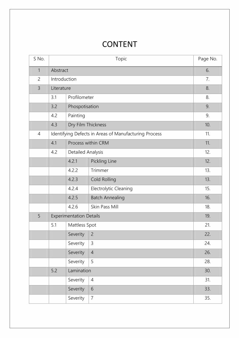
CONTENT
S No. Topic Page No.
1 Abstract 6.
2 Introduction 7.
3 Literature 8.
3.1 Profilometer 8.
3.2 Phospotisation 9.
4.2 Painting 9.
4.3 Dry Film Thickness 10.
4 Identifying Defects in Areas of Manufacturing Process 11.
4.1 Process within CRM 11.
4.2 Detailed Analysis
2
12.
4.2.1 Pickling Line 12.
4.2.2 Trimmer 13.
4.2.3 Cold Rolling 13.
4.2.4 Electrolytic Cleaning 15.
4.2.5 Batch Annealing 16.
4.2.6 Skin Pass Mill 18.
5 Experimentation Details 19.
5.1 Mattless Spot 21.
Severity 2 22.
Severity 3 24.
Severity 4 26.
Severity 5 28.
5.2 Lamination 30.
Severity 4 31.
Severity 6 33.
Severity 7 35.

6 | P a g e
5.3 Roll Mark/Dent 37.
Severity 2 38.
Severity 3 40.
Severity 4 42.
Severity 5 44.
5.4 Scratch 46.
Severity 2 47.
Severity 3 49.
Severity 4 51.
.
5.5 Gouge Mark 53.
Severity 4 54.
Severity 6 56.
6 Result & Discussion 58.
7 Conclusion 60.
8 References 61.
ABSTRACT
Increasing productivity by minimizing the defects is of utmost importance to any steel industry. Cold
Rolling Mill plays a very important role due to its very complex processes and the products end use.
Deliverance of high quality product to the customer, relentlessly understanding their requirement and
regular feedback became the basis for working on this project. During the process where a coil from
Hot Strip Mill (HSM) goes into the Pickling Line to Cold Rolling Mill to Batch Annealing to Final
Packaging and Dispatch amidst various other processes, it acquires various defects that need to be
catered before delivery to the customer. Some defects can be minimized through improvement in
maintenance and some are inherent (where CRM is a customer).
The aim of the project is form a quantitative comparative study with the help of profilometer analysis
of Raw CRCA, Phospotised CRCA, and Painted CRCA of stainless steel samples. On the basis of
comparison, one will be able to conclude upto what severity a particular defect will be passed.
Among the various defects analyzed by profilometer, the Lamination & Gouge Mark are the most
severed defects. The difference in total roughness obtained between defected and non-defected area
after 1st layer of painting was the order of 5 – 40 µm for Lamination & 8 – 10 µm for Gouge mark. This
shows that these defects are highly prone to customer complaints and often goes for rejection. The
difference upto 1 µm are passed without much scrutiny. Anything beyond 1 µm difference calls for
action by both manufacturer & customer.
Keywords: Cold Rolled Cold Annealed, Annealing, Surface Profilometer, Roughness, Flat product
Defects, Automobile Sheets
8 | P a g e
2 | INTRODUCTION
Defects are inherent to any manufacturing industry. A lot of resources and money is spent on
minimizing this.
Quantification of Defects helps reject defected pieces and manage mass production with ease. Cold
Rolling Mill or CRM is the customer of Automobile Customers. The CRCA coils produced is used in what
see as the everyday utility vehicles in the form of 2-Wheeler, 3-Wheeler and Multi Wheelers. Apart
from this, they are used in other several industries as well.
The same idea has been implemented, and this project tries to quantify the qualitative defects
produced in CRM.
The project is mainly divided into 4 main stages:
1. Collection of samples of different defects of varying severity (Range 1-7).
2. Conducting the profilometer test of Raw CRCA Sample before sending it for Phospotisation.
3. Conducting the Profilometer test of Phospotised sample before sending it for a layer of
painting.
4. Conducting the Profilometer test of Painted sample and performing a thorough comparison.
The comparison will help in ascertaining upto what severity a defect can be passed.

LITERATURE
3.1 | ABOUT PROFILOMETER
Profilometer is an instrument to measure a surface's profile, in order to quantify its
roughness. They are categorized as Contact and Non-Contact Profilometer [1].
Optical Profilometer, a non-contact type profilometer has been used in this project to the
study the surface’s profile. Optical Profile measures height variation. It provides accurate
surface measurements, produces high quality three-dimensional surface maps of the object
under test.
2D Surface Metrology:
Surface metrology is defined as a tool to measures
surface roughness by studying surface geometry as
shown in fig.
Measuring surface roughness is one of the
important concern for a wide range of industries
and applications. This includes auto component
wear, medical implant efficacy to various other
industrial application.
3D Surface Metrology
3D surface metrology uses 3D
surface profilers to provide a 3
dimensional perspective to the
surface, Fig: 3.1.2; these 3D
surface profilers using the light
wavelengths provides more
Fig: 3.1.1
Fig: 3.1.2
10 | P a g e
effective surface imaging and measurement.
3D surface metrology offers the opportunity to get the 3D dimensional perspective compared to cross
section analysis from 2D surface analysis.
Instrument Used:
About Wyko NT9100 Profiler:
Specification: Model - Vecco NT9100,
Magnification – 5X,
Measurement Array – 640 x 480,
Field of View – 1.2 mm.
3.2 | Phospotisation
Phosphatisation is a process of treating the steel to create a layer of phosphate on its surface whereby
metal phosphate layers are formed on base material which are hardly soluble.
The main areas of application/advantages include:
Temporary corrosion protection for steel, when stored for limited period of time.
Improving the sliding properties when cold forming steel.
Improved powder and paint coating adhesions.
The most common phosphating chemistry include iron phosphate, zinc phosphate, manganese
phosphate. The Phosphating may be a 3 or 5 stage process. The 3 stage process takes into account
Clean/Phosphate, Rinse, Rinse/Seal and the 5 stage process proceeds as Clean, Rinse, Activated Rinse,
Phosphate, Rinse.
The one utilised during these experiments is the Titanium Phosphate.
3.3 | Painting
After the Raw CRCA samples have been phosphatised, the samples are subjected to ED. Then 2-3 layers
of Spray/other form of Painting is carried out on the CRCA sheets [2]. Different automobiles
manufacturers follow different practices accounting for different thickness of layers of paint. This may
be followed by an optional layer of lacker to provide optimum finish to the auto components.
Fig: 3.1.3

Dry Film Thickness
Various coatings are incorporated on the Raw CRCA sample before the end utilisation by the
customers in form of Automobiles.
The first layer of painting should have a minimum Dry Film Thickness (DFT). This is equivalent to 30
microns for Spray Painting.
After putting the first layer of spray paint, the sample was put in the oven at the temperature of 105-
110º C for 20 minutes for surface drying and optimum finish.

12 | P a g e
4 | IDENTIFYING DEFECTS IN AREAS OF MANUFACTURING PROCESS
The primary input material to the cold rolling complex is hot rolled coils. The cold rolled
products are broadly under the categories: (a) annealed coils (b) galvanised coils and (c) cold
rolled full hard coils.
The cold rolled products from the CRM Complex are designed to cater to various market
segments such as construction, general engineering, automobile, white goods, packaging etc.
4.1 | Process within CRM:
Pickling Line
Trimmer
Cold Rolling Mill
Electrolytic cleaning
Batch Annealing
Skin Pass Mill
Re-Coiling Line
Packing and Despatch
Fig: 4.1.1
4.2 | DETAILED ANALYSIS
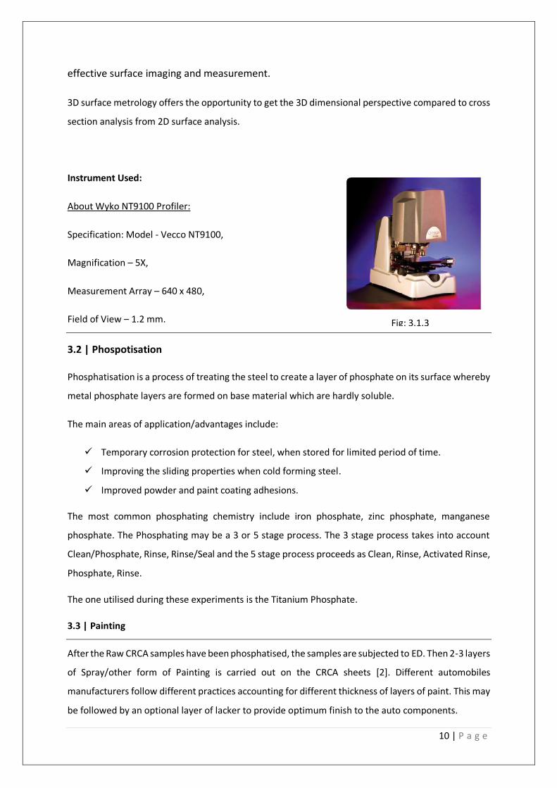
4.2.1 | Pickling Line
Pickling is an important stage in the process sequence prior to cold rolling. Hot rolled coil serve
as the input material for the cold rolling. It has an oxide film or scale on their surface. Pickling
eliminates these oxides on the hot rolled strip surface to facilitate subsequent cold rolling. In
pickling, the surface of strip is passed through an inorganic acid (hydrochloric or sulphuric
acid). The strip is passed through acid bath to remove the oxide.
Defect due to Poor Pickling
Under pickling/ Black Patch should not be there. Arises due to pickling stoppages (pickling
tank, entry trouble, welder, trimmer, chopper).
Fig: 4.2.1
Fig: 4.1.2
14 | P a g e
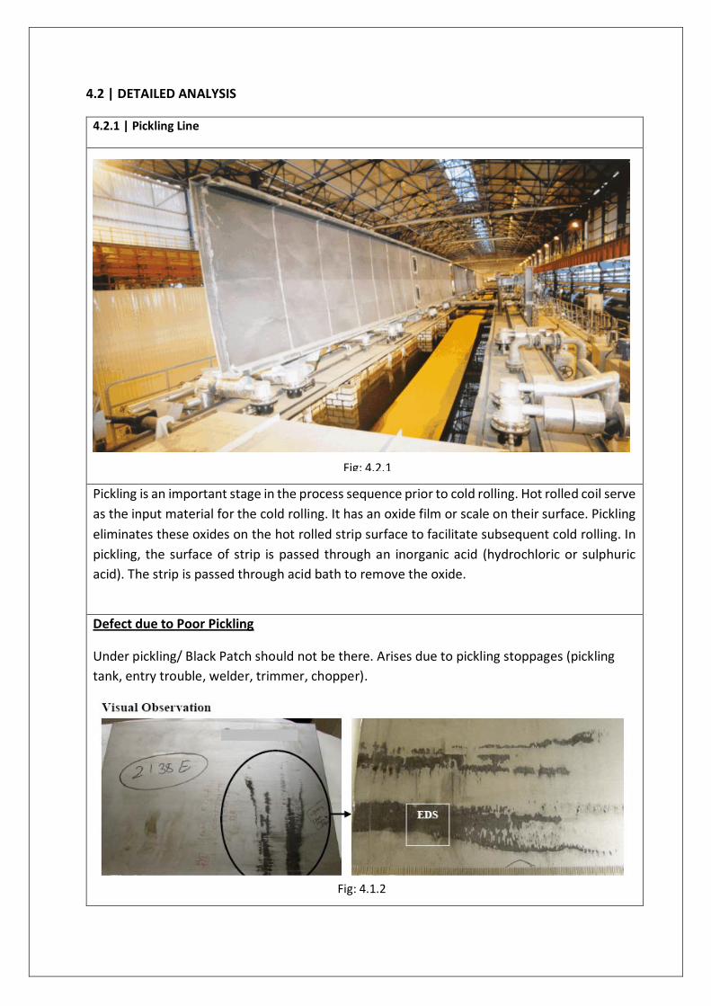
4.2.2 | Trimmer
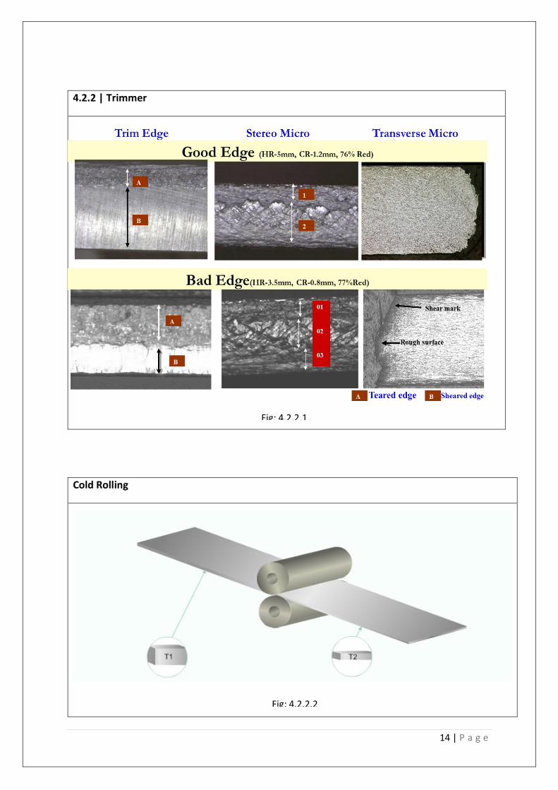
Cold Rolling
Fig: 4.2.2.1
Fig: 4.2.2.2
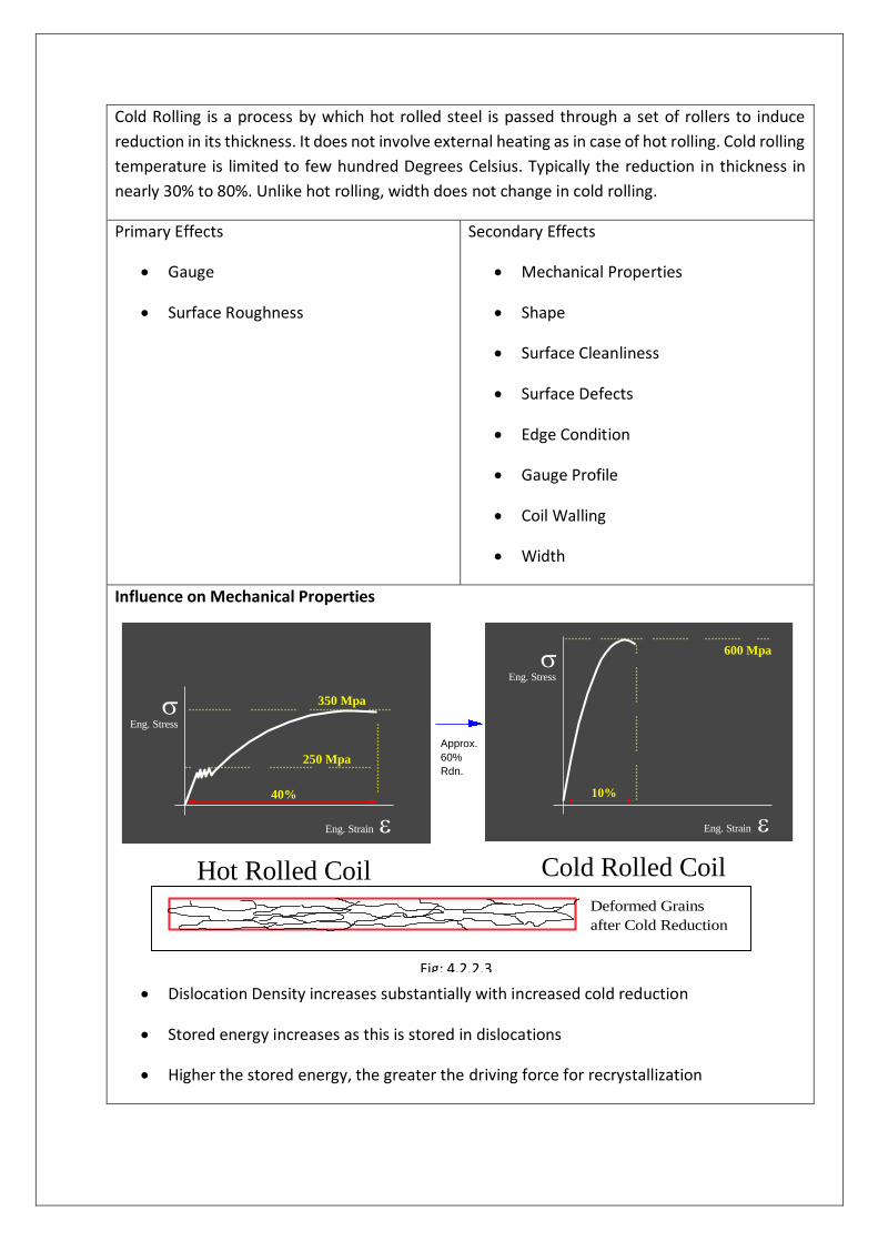
Cold Rolling is a process by which hot rolled steel is passed through a set of rollers to induce
reduction in its thickness. It does not involve external heating as in case of hot rolling. Cold rolling
temperature is limited to few hundred Degrees Celsius. Typically the reduction in thickness in
nearly 30% to 80%. Unlike hot rolling, width does not change in cold rolling.
Primary Effects
Gauge
Surface Roughness
Secondary Effects
Mechanical Properties
Shape
Surface Cleanliness
Surface Defects
Edge Condition
Gauge Profile
Coil Walling
Width
Influence on Mechanical Properties
Dislocation Density increases substantially with increased cold reduction
Stored energy increases as this is stored in dislocations
Higher the stored energy, the greater the driving force for recrystallization
Eng. Stress
Eng. Strain
250 Mpa
350 Mpa
40%
Hot Rolled Coil
Eng. Stress
Eng. Strain
600 Mpa
10%
Cold Rolled Coil
Approx.
60%
Rdn.
Deformed Grains
after Cold Reduction
Fig: 4.2.2.3
16 | P a g e
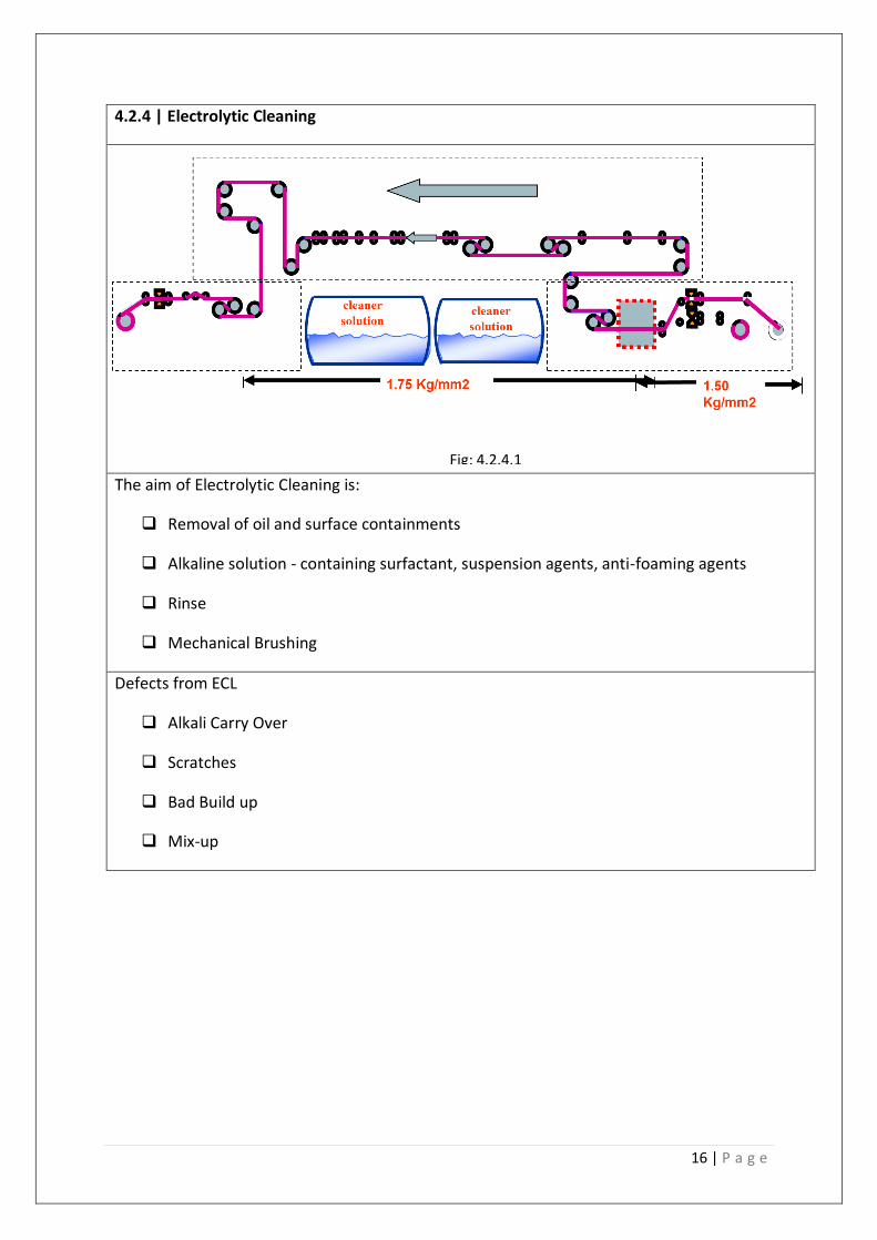
4.2.4 | Electrolytic Cleaning
The aim of Electrolytic Cleaning is:
Removal of oil and surface containments
Alkaline solution - containing surfactant, suspension agents, anti-foaming agents
Rinse
Mechanical Brushing
Defects from ECL
Alkali Carry Over
Scratches
Bad Build up
Mix-up
Fig: 4.2.4.1
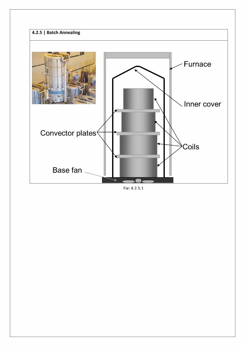
4.2.5 | Batch Annealing
Fig: 4.2.5.1
18 | P a g e
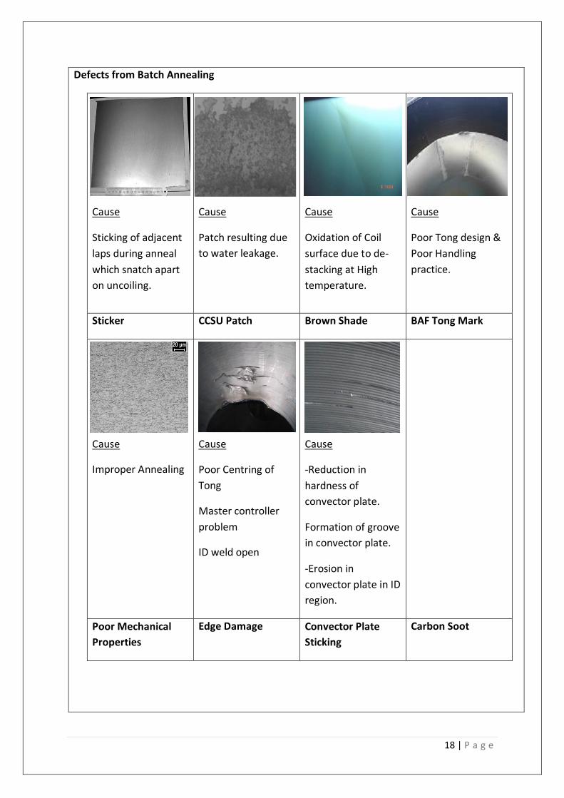
Defects from Batch Annealing
Cause
Sticking of adjacent
laps during anneal
which snatch apart
on uncoiling.
Cause
Patch resulting due
to water leakage.
Cause
Oxidation of Coil
surface due to de-
stacking at High
temperature.
Cause
Poor Tong design &
Poor Handling
practice.
Sticker CCSU Patch Brown Shade BAF Tong Mark
Cause
Improper Annealing
Cause
Poor Centring of
Tong
Master controller
problem
ID weld open
Cause
-Reduction in
hardness of
convector plate.
Formation of groove
in convector plate.
-Erosion in
convector plate in ID
region.
Poor Mechanical
Properties
Edge Damage Convector Plate
Sticking
Carbon Soot
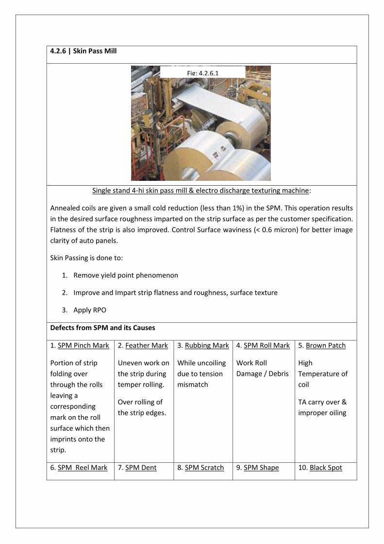
4.2.6 | Skin Pass Mill
Single stand 4-hi skin pass mill & electro discharge texturing machine:
Annealed coils are given a small cold reduction (less than 1%) in the SPM. This operation results
in the desired surface roughness imparted on the strip surface as per the customer specification.
Flatness of the strip is also improved. Control Surface waviness (< 0.6 micron) for better image
clarity of auto panels.
Skin Passing is done to:
1. Remove yield point phenomenon
2. Improve and Impart strip flatness and roughness, surface texture
3. Apply RPO
Defects from SPM and its Causes
1. SPM Pinch Mark
Portion of strip
folding over
through the rolls
leaving a
corresponding
mark on the roll
surface which then
imprints onto the
strip.
2. Feather Mark
Uneven work on
the strip during
temper rolling.
Over rolling of
the strip edges.
3. Rubbing Mark
While uncoiling
due to tension
mismatch
4. SPM Roll Mark
Work Roll
Damage / Debris
5. Brown Patch
High
Temperature of
coil
TA carry over &
improper oiling
6. SPM Reel Mark 7. SPM Dent 8. SPM Scratch 9. SPM Shape 10. Black Spot
Fig: 4.2.6.1

20 | P a g e
5 | EXPERIMENTAL DETAILS
Experimentation:
A total of 40 samples cut in the size of 20 cm x 15 cm are taken for the experiment. A two dimensional
(2-D), three dimensional (3-D), X, Y Profile are generated for each sample for each of the three cases
– Raw CRCA sample, Phospotised Sample, After Painted sample. A scanned image for each of the 3
cases is also taken to have a naked eye observation. The following “Scanned Images” for each of the
3 cases gives a brief idea how they look from the naked eye:
Fig 5.1: Raw CRCA Sample (20 cm x 15 cm) Fig 5. 2: Phospotised CRCA Sample (20 cm x 15 cm)
Fig 5.3: Painted CRCA Sample (20 cm x 15 cm)
The layer of Phosphate is of the order of 1-2 microns and the layer of paint is the order of 30 microns.
A similar profilometer test is conducted on the in-market automobile sample. The total thickness
include the phosphate is of the order of 100 – 130 microns.

The following gives an idea of the 2-D & 3-D figure generated by the profilometer.
Fig 5.4: 2-D Interactive Display for a defected Fig 5.5: 3-D Interactive Display for a defected sample.
The following figure shows the X & Y Profile of the CRCA sample.
Fig 5.6: X-Profile of the CRCA sample Fig 5.7: Y-Profile of the CRCA sample
Similar Cup Test was carried out for another set of samples collected separately to check for failure of
the samples.
Experimental analysis of all the defect against the available severity has been carried out.
22 | P a g e
5.1 | DEFECT: MATTLESS SPOT
Definition:
Matteless spot are caused by carbon soot, dirt or iron fines on strip pickup by the roll in certain
areas while rolling in Skin Pass Mill. This results in insufficient transfer of matte to the strip
surface. This insufficient transfer of matte on strip surface is called as Matteless spot. The
following are the severity of Mattless Spot collected for experimental analysis.
SEVERITY – 2 | 3 |4 | 5
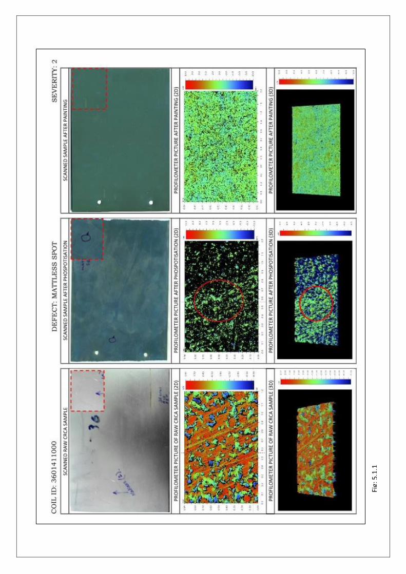
Fig:
5.1
.1

24 | P a g e
Fig:
5.1
.2

Fig:
5.1
.3

26 | P a g e
Fig:
5.1
.4
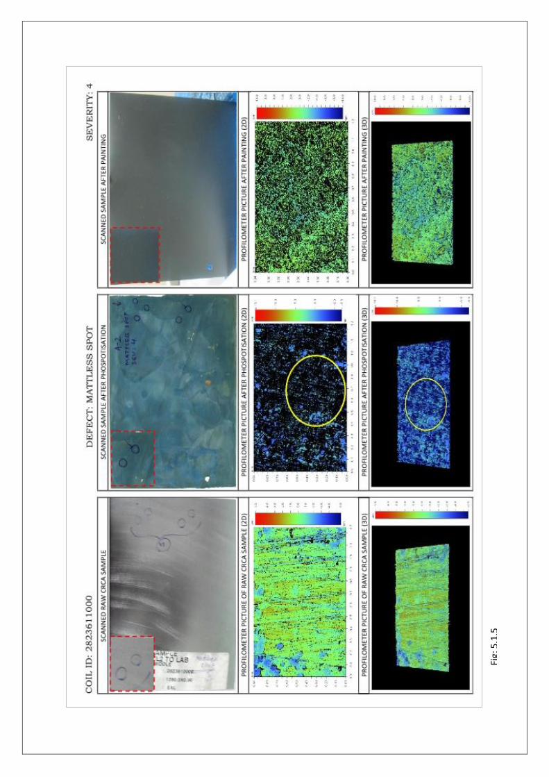
Fig:
5.1
.5

28 | P a g e
Fig:
5.1
.6
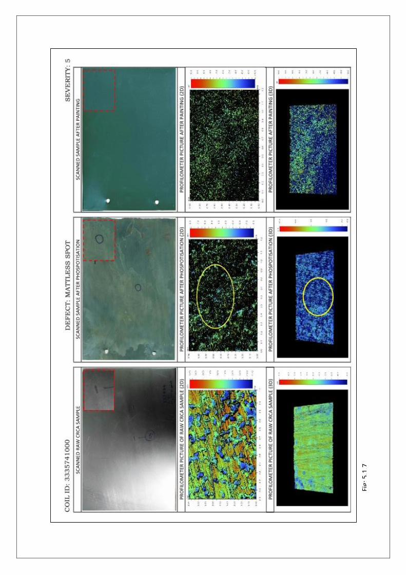
Fig:
5.1
.7
30 | P a g e
e
Fig:
5.1
.8
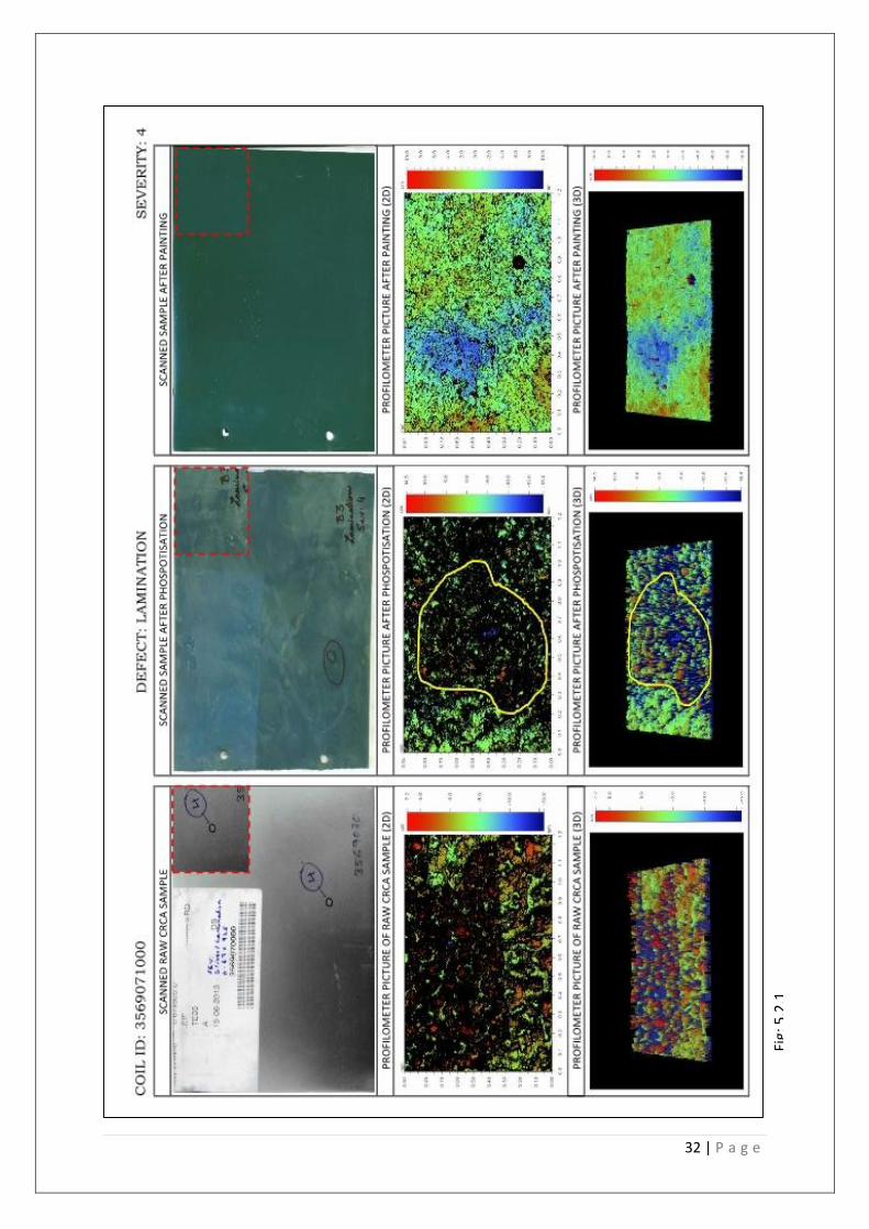
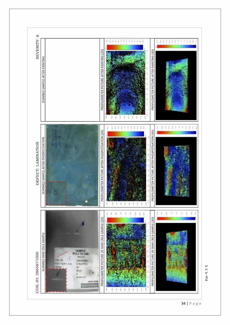
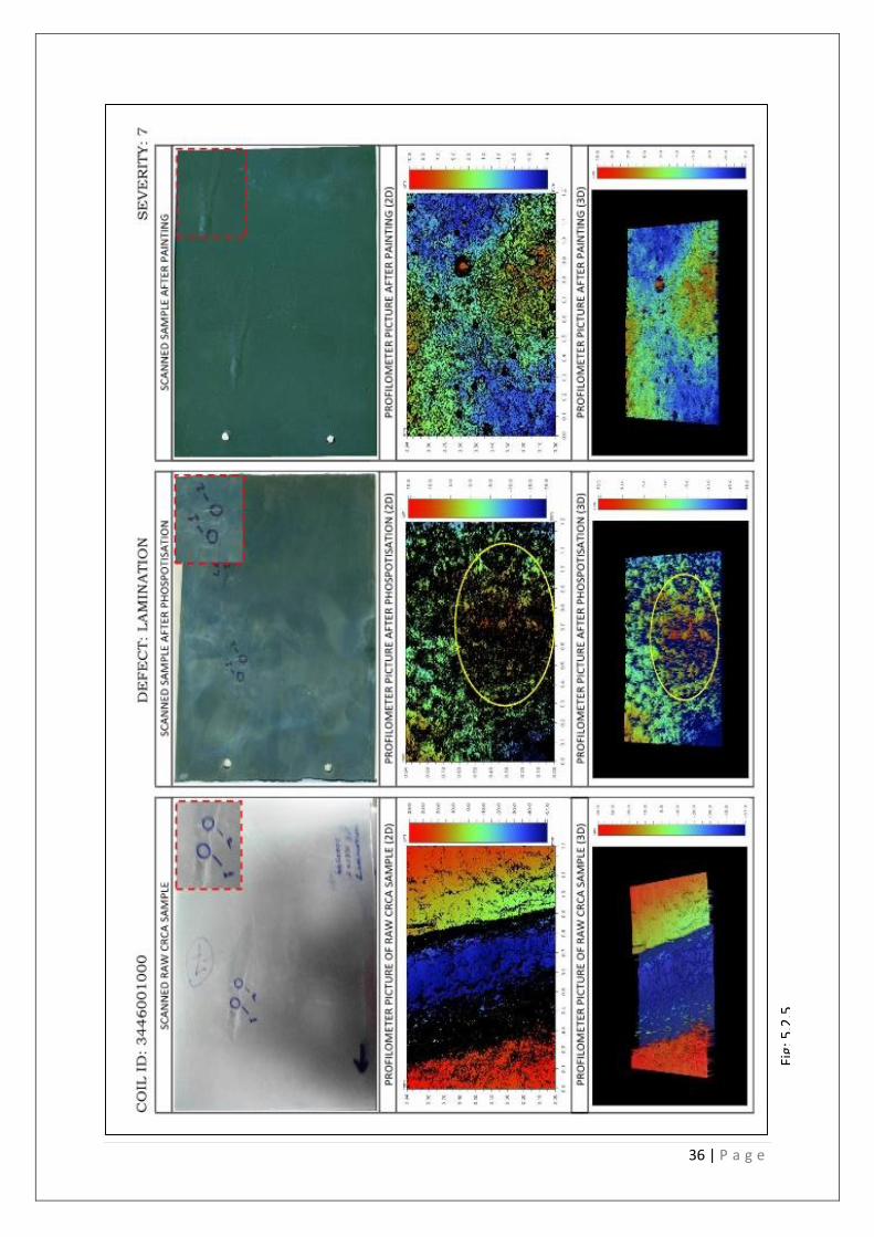
5.2 | LAMINATION
Definition This is the slag and oxidized metallic inclusions at the surface of the internal pipe due to solidification shrinkage prevent welding during hot rolling. This defect is similar to sliver but the peeling surface is more extensive. Causes -This defect may arise from exposed blowholes. When surface have oxidized and fail to weld up during hot rolling. -Inadequate dropping of slab.
SEVERITY – 4 | 6 | 7
32 | P a g e
Fig:
5.2
.1
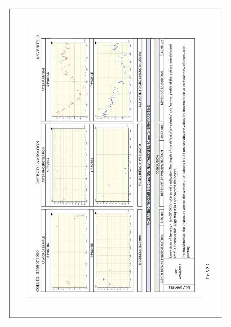
Fig:
5.2
.2
34 | P a g e
Fig:
5.2
.3
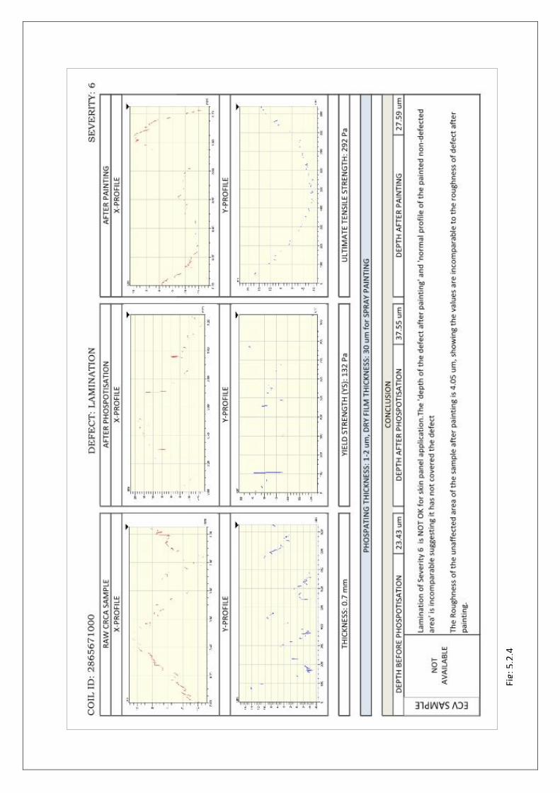
Fig:
5.2
.4
36 | P a g e
Fig:
5.2
.5

Fig:
5.2
.6
38 | P a g e
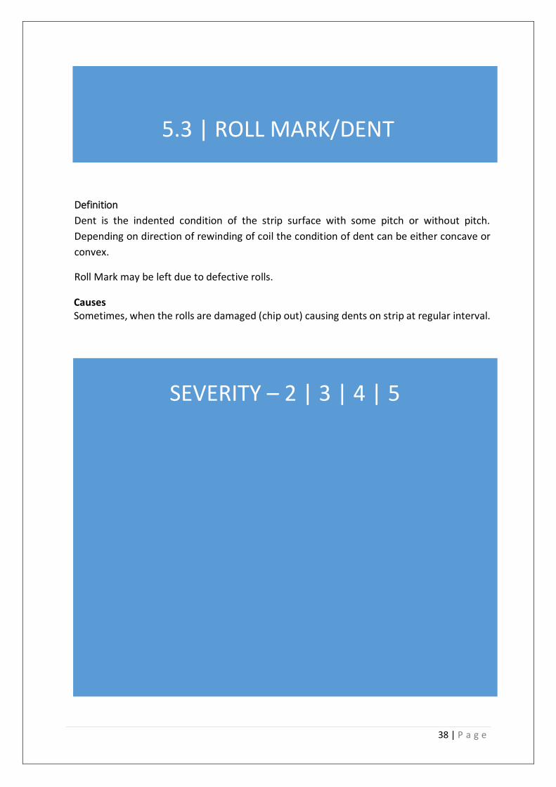
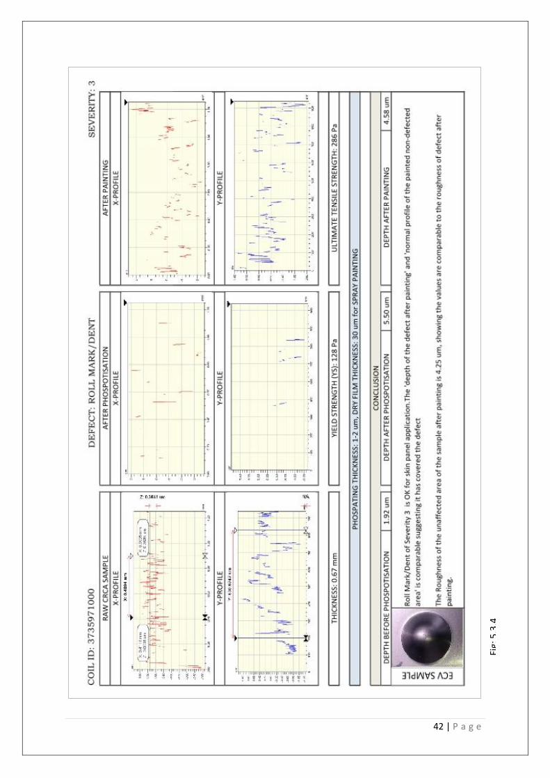
5.3 | ROLL MARK/DENT
Definition
Dent is the indented condition of the strip surface with some pitch or without pitch.
Depending on direction of rewinding of coil the condition of dent can be either concave or
convex.
Roll Mark may be left due to defective rolls.
Causes Sometimes, when the rolls are damaged (chip out) causing dents on strip at regular interval.
Remedy
Changed the damaged roll whenever required or condition the rolls time to time.
SEVERITY – 2 | 3 | 4 | 5
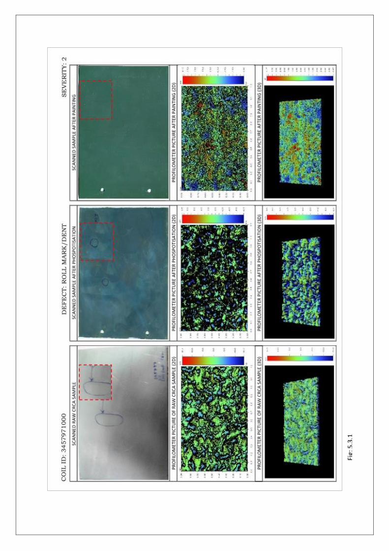
Fig:
5.3
.1
40 | P a g e
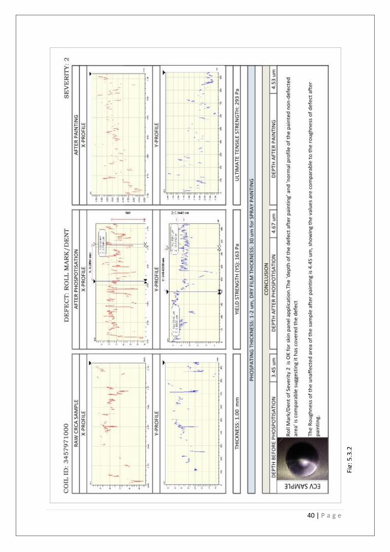
Fig:
5.3
.2
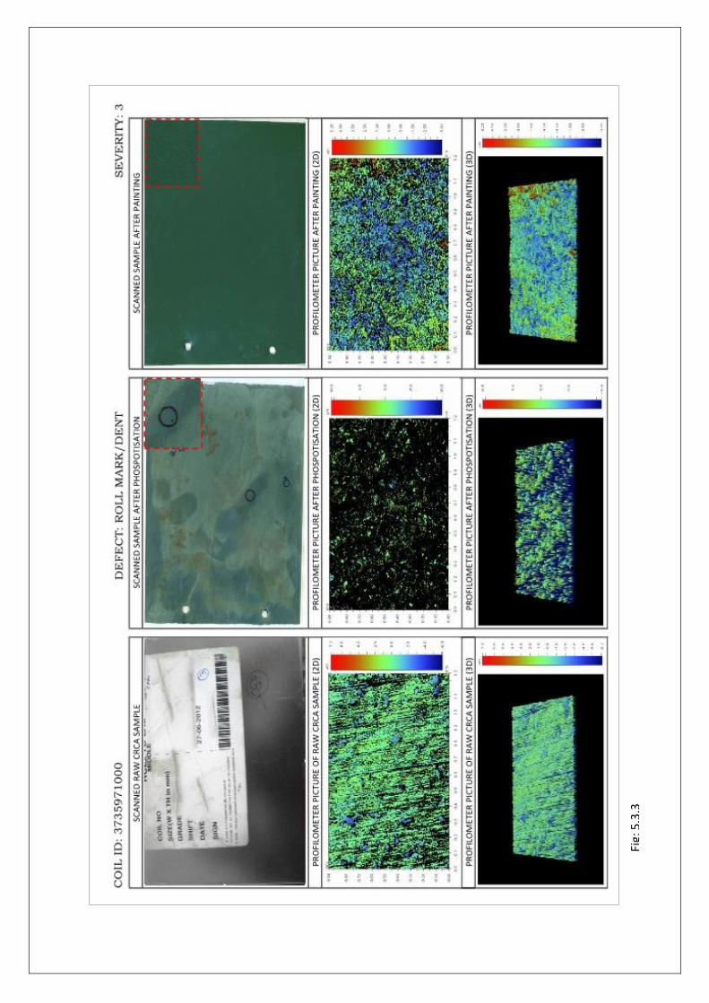
Fig:
5.3
.3
42 | P a g e
Fig:
5.3
.4
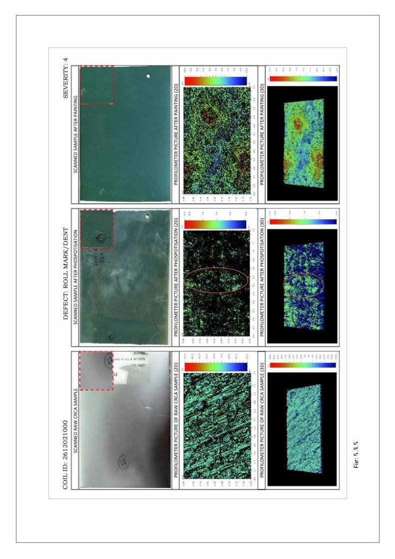
Fig:
5.3
.5

44 | P a g e
Fig:
5.3
.6

Fig:
5.3
.7

46 | P a g e
Fig:
5.3
.8

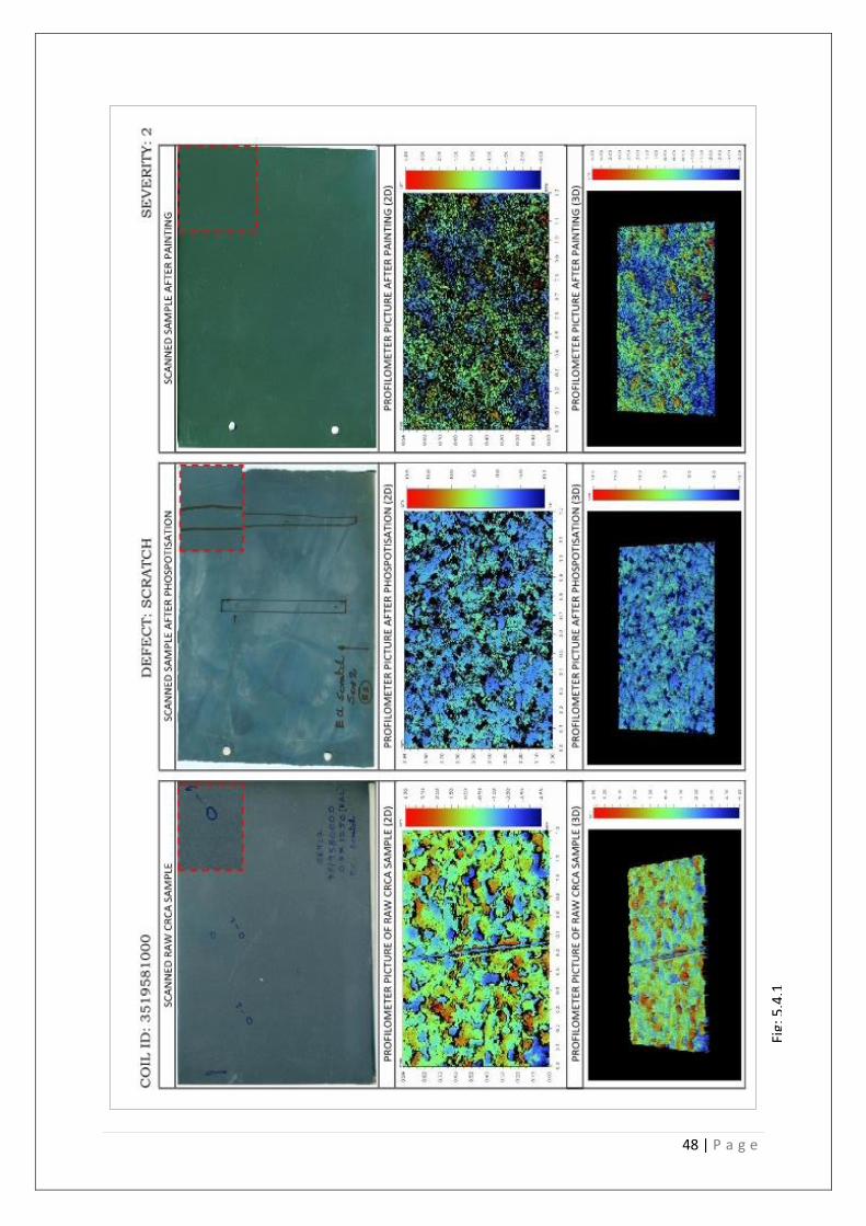
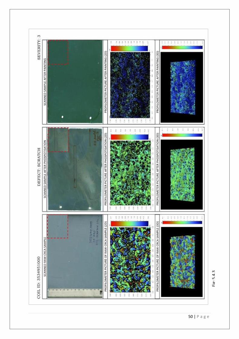
5.4 | SCRATCH
Definition During processing of cold rolled coil it passes through various processing lines. During processing if sheets gets in contact with any stationary part / equipment of the line or non-rotating roll that will lead to a scratch mark on the sheet.
SEVERITY – 2 | 3 | 4
48 | P a g e
Fig:
5.4
.1

Fig:
5.4
.2
50 | P a g e
Fig:
5.4
.3

Fig:
5.4
.4

52 | P a g e
Fig:
5.4
.5
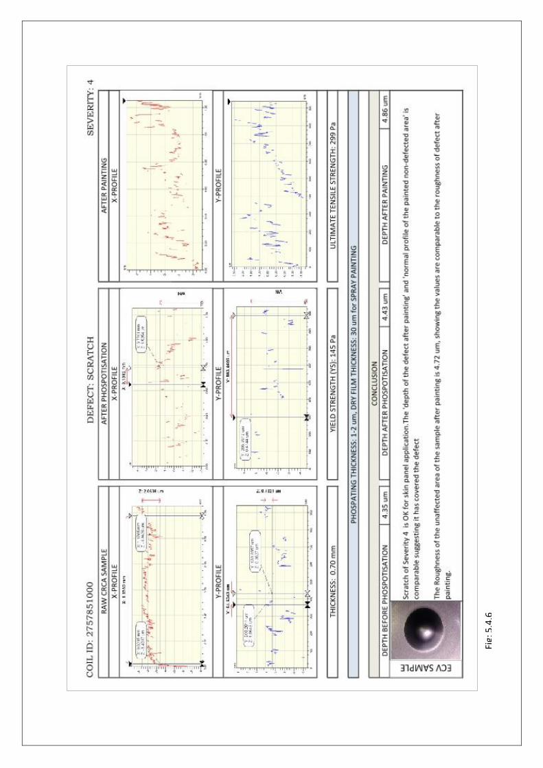
Fig:
5.4
.6

54 | P a g e
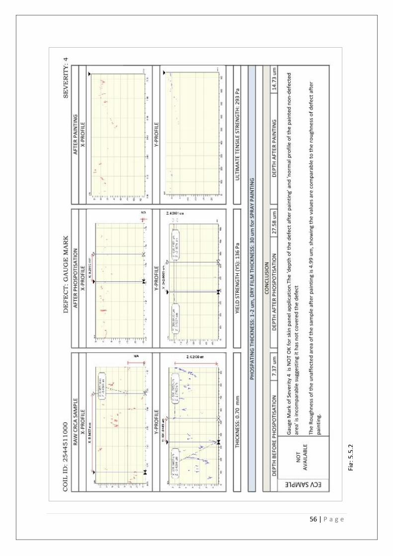
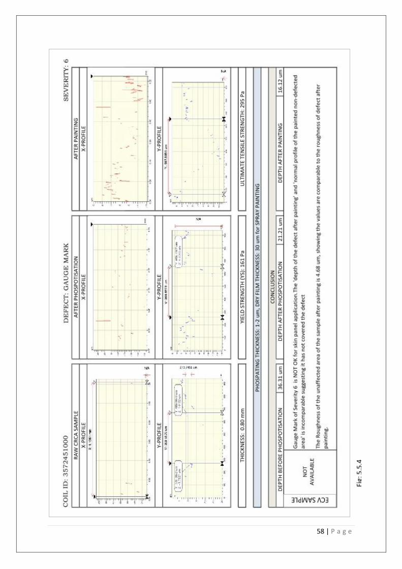
5.5 | GOUGE MARK
Definition This erupts in rolling direction. Some are pit type and others appear only as surface pattern, relatively long (Slip scratches). Mostly these are hot strip scratches of various dimensions and sometimes it undergoes a small degree of over rolling / lapping. If the strip is damaged in its hot condition, the defect undergoes scaling and may be rolled closed.
Causes:-
i. This defect is caused by Hot Mill guide device, etc. is rolled down for less depth and
discoloured to dull appearance.
ii. This defect also caused by guide device at Pickling or Cold Rolling Process.

Fig:
5.5
.1
56 | P a g e
Fig:
5.5
.2

Fig:
5.5
.3
58 | P a g e
Fig:
5.5
.4

6 | RESULT AND DISCUSSION
The following table gives an overall picture to the experiments carried out above
Roughness Rp (Peak) Rv (Valley) Rt [(Total) = (Peak+Valley)] Rt: AFTER PAINT
(GENERAL SURFACE)
DEFECT SEV BEFORE AFTER
AFTER PAINT BEFORE AFTER
AFTER PAINT BEFORE AFTER
AFTER PAINT BEFORE AFTER
AFTER PAINT
MATTLESS SPOT
2 0.72 0.58 0.65 1.72 1.63 1.76 2.99 0.87 1.95 4.72 2.49 3.71 3.45
MATTLESS SPOT
3 0.72 0.82 0.48 1.98 1.54 1.71 2.40 1.87 0.54 4.38 3.37 2.25 2.88
MATTLESS SPOT
4 0.60 0.53 0.59 2.20 1.96 1.47 2.10 4.13 1.57 4.30 6.09 3.04 2.88
MATTLESS SPOT
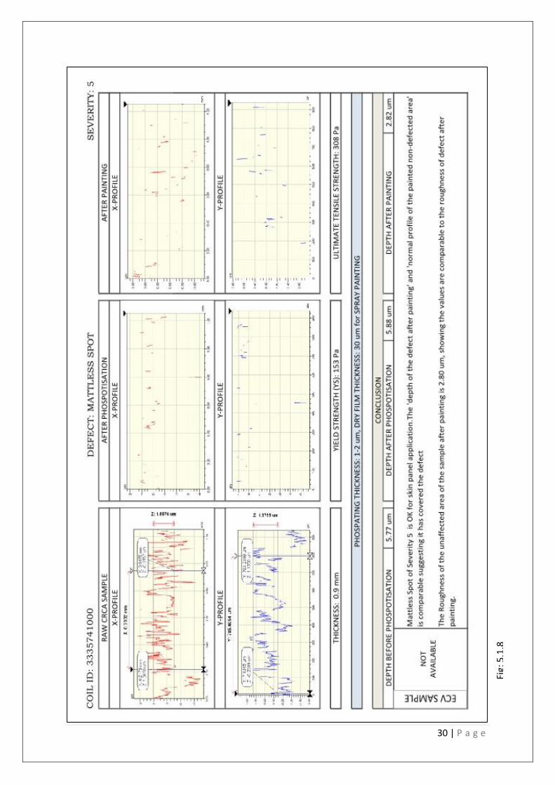
5 0.79 1.00 0.64 2.22 2.63 1.57 3.49 3.25 1.25 5.70 5.88 2.82 2.80
LAMINATION 4 1.04 2.02 2.10 3.80 6.24 5.17 1.70 13.31 5.28 5.50 19.58 10.45 3.93
LAMINATION 6 4.65 10.15 6.89 11.53 20.71 9.85 11.90 16.84 17.74 23.43 37.55 27.59 4.05
LAMINATION 7 26.78 19.08 12.64 26.74 42.28 19.92 47.85 36.91 20.17 74.59 79.19 40.09 4.33
ROLL MARK/Dent
2 0.88 1.08 0.70 2.24 3.36 1.69 2.21 5.71 2.84 3.45 4.67 4.53 4.45
ROLL MARK/Dent
3 0.35 1.39 0.72 1.07 1.97 2.29 0.85 3.54 2.29 1.92 5.50 4.58 4.25
ROLL MARK/Dent
4 0.91 1.12 0.82 3.42 3.35 1.54 1.79 2.08 3.38 5.21 5.61 4.92 3.64
ROLL MARK/Dent
5 0.59 0.94 0.78 2.87 1.28 2.92 2.25 2.07 2.24 5.13 3.36 5.16 4.73
SCRATCH 2 1.26 0.65 0.61 2.49 2.86 1.78 2.81 1.08 1.72 5.31 3.94 3.50 3.46
SCRATCH 3 1.88 1.49 0.99 4.83 5.20 1.97 3.51 6.34 1.95 8.34 11.54 3.92 3.81
SCRATCH 4 0.32 1.22 0.81 2.29 2.74 2.46 2.06 1.69 2.40 4.35 4.43 4.86 4.72
GAUGE MARK
4 1.60 14.14 1.54 3.38 3.69 2.20 4.00 23.90 12.53 7.37 27.58 14.73 4.99
GAUGE MARK
6 1.28 1.56 1.09 14.92 3.34 5.27 21.39 17.87 10.85 36.31 21.21 16.12 4.68
Fig 6.1: Profilometer analysis of the Defected - Raw CRCA sample, Phospotised CRCA, After Paint
CRCA; General Surface (After paint) sample. Note: All numerical figures are in micrometer.
The defects encountered were Mattless Spot, Lamination, Roll Mark/ Dent, Scratch & Gauge
Mark. The Scratch defects includes ECL, TCM, SPM & RCL. The ECL scratch was approximately
2 micrometer higher than other types of scratch and so were considered together.
60 | P a g e
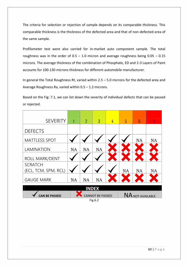
The criteria for selection or rejection of sample depends on its comparable thickness. This
comparable thickness is the thickness of the defected area and that of non-defected area of
the same sample.
Profilometer test were also carried for in-market auto component sample. The total
roughness was in the order of 0.5 – 1.0 micron and average roughness being 0.05 – 0.15
microns. The average thickness of the combination of Phosphate, ED and 2-3 Layers of Paint
accounts for 100-130 microns thickness for different automobile manufacturer.
In general the Total Roughness Rt, varied within 2.5 – 5.0 microns for the defected area and
Average Roughness Ra, varied within 0.5 – 1.2 microns.
Based on the Fig: 7.1, we can list down the severity of individual defects that can be passed
or rejected.
INDEX
CAN BE PASSED CANNOT BE PASSED NA NOT AVAILABLE Fig 6.2
SEVERITY 1 2 3 4 5 6 7
DEFECTS
MATTLESS SPOT
NA NA
LAMINATION NA NA NA
ROLL MARK/DENT
SCRATCH
(ECL, TCM, SPM, RCL)
NA NA NA
GAUGE MARK NA NA NA

7 | CONCLUSION
This study has made a detailed profilometer analysis of defected CRCA Stainless Steel obtained from
SPM, ECL, RCL, PLTCM, LD2, HSM samples in its Raw, Phospotised, and Painted form. The
quantification of qualitative defects throws a new dimension and some important conclusions drawn
from the results presented here are:
1. Mattless Spot up to 5 Severity range can be passed. The difference in total roughness obtained
between defected and non-defected area after 1st layer of painting was the order of 0.2 – 0.5
µm.
2. Lamination with the severity range of 4-7 cannot be passed. The difference in total roughness
obtained between defected and non-defected area after 1st layer of painting was the order of
5 - 40 µm.
3. Roll Mark/Dent up to 3 Severity can be passed. The difference in total roughness obtained
between defected and non-defected area after 1st layer of painting was the order of 0.25 –
1.5 µm.
4. Scratch up to 4 Severity can be passed. The difference in total roughness obtained between
defected and non-defected area after 1st layer of painting was the order of 0.2 – 0.4 µm.
5. Gouge Mark from Severity 4-7 cannot be passed. The difference in total roughness obtained
between defected and non-defected area after 1st layer of painting was the order of 8 – 10
µm.

62 | P a g e
8| REFERENCES
1. Center for Engineering and Physical Science Research, Columbia University;
http://www.clean.cise.columbia.edu/equipment/equipmentlist/122-wyko-nt9100-
profiler
2. Improved surface quality of exposed automotive steels by J. G. Speer, D. K. Matlock,
N. Myers, and Y. M. Choi; October 10, 2002