quality of service and quality of experience measurements on ip
TRANSCRIPT

1
Quality of Service and Quality of Experience Measurements
on IP Multicast Based IPTV Systems
Gábor Lencse, Balázs Steierlein
SZE, 9026 Győr, Egyetem tér 1. Phone: +36 96 613 665, fax: +36 96 613 646
e-mail: [email protected], [email protected]
Abstract: The essential protocols of IP multicast based IPTV systems (IGMP, PIM-SM) are introduced. The operation of the IP multicast based IPTV systems is demonstrated on a small test network. The bandwidth requirement of the multicast and unicast based IPTV systems are compared. The value of different Quality of Service parameters (packet loss, jitter, IGMP latency) and their effect to the Quality of Experience are measured.
Keywords: quality of service, quality of experience, IPTV, IP multicast, IGMP, PIM-SM
1. Introduction ITU-T defines Internet Protocol Television (IPTV) as “Multimedia services such as
television/video/audio/text/graphics/data delivered over IP-based networks managed to support the required level of QoS/QoE, security, interactivity and reliability.” [1] From this definition, it is evident that IPTV is different form multimedia services over the public Internet; IPTV requires a managed network to guarantee the required level of the properties mentioned in the definition above.
Why is bare bandwidth not enough? What more properties should the networks have and how do they influence the users’ satisfaction with the services? The IPTV definition above motivates the investigation of several aspects, out of which we have chosen the Quality of Service (QoS) and the Quality of Experience (QoE). The first one can be described by quantities such as network delay, jitter, packet loss, bit error rate, etc. that can be measured at network level. The second one means the quality of the users’ experience which is subjective. It can be measured by Mean Opinion Score (MOS) methods. According to the current industrial practices, upper limits are defined for some QoS parameters and if these limits are kept, the users should be satisfied. Some more precise relationships between QoS and QoE will be shown later in this paper.
Another important issue is the use of IP multicast. It will be shown that this is the only sane way of servicing a high and rapidly growing number of IPTV subscribers.

2
Multimedia Research Group forecasts an annual grow rate of 26% in the number of global IPTV subscribers for the time interval from 2010 to 2014. [2] This growth gives us a good reason to deal with the topic.
The remainder of this paper is organised as follows. First, IP multicast systems and their most important and widely used protocols (IGMP and PIM-SM) are introduced. Second, the operation of the IP multicast is demonstrated on a test network. Third, the bandwidth requirement of the multicast streaming and that of the unicast streaming are compared. Fourth, the effect of the value of different QoS parameters to the QoE is examined. Finally, the paper is closed with the conclusions.
2. IP multicast systems Our current most well known IP based applications/protocols (such as HTTP, FTP,
SMTP, DNS, etc.) use unicast addressing at IP level: a packet (IP datagram) is travelling from one host to another single host. In contrast, IP multicast means that an IP packet sent from one host should arrive to multiple hosts, the members of an IP multicast group. The number of the members of an IP multicast group can be arbitrarily high and the resource consumption of the sending of a packet is not at all increasing with the number of the receivers. It can be possible by sending the packet to a group IP address as destination address. The most important protocols of IP multicasting will be briefly introduced in the following subsections.
2.1. Internet Group Management Protocol
Internet Group Management Protocol (IGMP) is used by the hosts to join to or to leave a group. It is taken place between the hosts and the first-hop router. IGMP has 3 versions. IGMPv1 (described in RFC 1112) is now obsolete and is no more in use. IGMPv2 (RFC 2236) is the most widely used version in current IPTV systems, but IGMPv3 (RFC 3376) has new functionalities and may replace IGMPv2 later. In the following we focus on IGMPv2 as is it the most appropriate one for our research.
How IGMP works? The multicast router periodically sends an IGMP Host Membership Query message (shortly Query), to find out which groups have members. This Query is sent to the all-hosts IP multicast address (224.0.0.1), thus the messages is delivered to all the hosts residing on the given network. The TTL (Time to Live) value of the datagram carrying the Query message is always set to 1. Thus the Query message may not be delivered to hosts on a different network. The group members will reply with a Host Membership Report message (shortly Report). The following method is used to avoid the congestion of the report messages. The hosts do not reply promptly, but after the expiry of a random timer only. The replying hosts set the address of the group that they are members of as the destination IP address of the Report message thus it will be delivered to all the hosts (on the local network) belonging to the given group. If a host receives a Report message before the expiry of its own random timer then the host withdraws its own Report message. In this way, the router receives a single Report message per groups only. This is enough, because if there is even a single member of a group connected to the router, the router must forward the multicast stream.

3
If a host joins to an empty group (a group that has no members) then the host will not wait until a Query message, but sends a Report message to the router indicating its intention to be the first member of the group. To avoid the risk of the Report message being lost, the host should repeat the message within a short time period.
If there are multiple IGMP capable routers on a network then the so called IGMP Querier Election mechanism is used to decide which one should send the Query messages on the a network. (The router having the IP address with the smallest numeric value will be the Querier. To decide this, the routers send general Queries to all the networks they are connected to. All the IGMP capable routers start in Querier state and may change later to Non-Querier state.)
In IGMPv2, the hosts are able to send Leave messages. (Lacking this function, IGMPv1 is not suitable for group management is IPTV systems.) This message is sent to the all-routers IP multicast address (224.0.0.2). When a router receives a Leave message it sends a group specific Query message to the group that was specified in the Leave message. If the router does not receive an answer (a Report message) before the expiry of the Max Response Time then the router will consider the group empty. Using this solution with the Leave message, it turns out for the router very soon that a stream has no more listener so the router does not have to deliver the stream unnecessarily until the next periodic membership query.
IPv6 uses the Multicast Listener Discovery (MLD) protocol instead of IGMP. MLD operates in the same way as IGMP, except that MLD uses ICMPv6 to carry its messages. See RFC 2710 for more information.
2.2. Protocol Independent Multicast - Sparse Mode
Protocol Independent Multicast builds multicast trees on the basis of routing information obtained from a unicast routing protocol (e.g. RIP, OSPF) – this is why it is called protocol independent. It has four variants, out of which the two most important ones are:
1. PIM-Sparse Mode is the most widely used multicast routing protocol. PIM-SM does not suppose group members everywhere thus sends multicast traffic into those directions where it has been requested.
2. PIM-Dense Mode builds the multicast trees by flooding the whole network by multicast traffic and then pruning back the branches of the traffic distribution tree where no receivers of the multicast traffic are present.
In the rest of this paper, we use PIM-SM (RFC 2362). This protocol can be used for multicast routing within one Autonomous System (AS). PIM-SM does not have an own topology discovery method, but uses the Routing Information Base (RIB) of the unicast routing protocol applied in the AS. With the help of this "outer" RIB, PIM-SM builds its own Multicast Routing Information Base (MRIB). Unlike unicast RIB (that specifies the next router towards the destination of the packets) MRIB specifies the reverse path from the subnet to the router.

4
The operation of PIM-SM has the following three phases.
2.2.1. Building a Rendezvous Point Tree from the receives to RP
In the first phase, the Rendezvous Point Tree (RP-tree) is being built in the following way. The receivers send their IGMP (or MLD) Join messages with the required group address as destination IP address. The Designated Router (DR) of the receiver (that was elected from among the local routers before) receives the IGMP Join message and sends a PIM Join message to the RP. This PIM Join message travels through the routers in the network and the RP-tree is being built. The PIM Join messages have the marking: (*,G). The first element is the IP address of the streaming source, and the second one is the IP address of the multicast group. The * means, that when a receiver joins a group, it will receive the traffic from all the sources that send steam to multicast group G. The PIM Join messages do not need to travel until the RP, it is enough to reach a point where the RP-tree is already built. This is why RP-tree is also called shared tree. The PIM Join messages are resent while there is at least a single member in the group. When the last receiver leaves the group then DR sends a (*,G) PIM Prune message to prune the tree until the point where there are other receivers connected.
2.2.2. Registration, building SPT from RP to the source and Register-stop
In the second phase, when a data source first sends to a group, the first hop router (DR) of the source encapsulates the data packets of the source into unicast messages called Register messages and send them to RP. From the Register messages, the RP router knows that the source is ready to send the stream. RP decapsulates the Register messages, and forwards the contained streaming data message to the appropriate multicast group (if it has at least a single member). In addition to this, RP sends an (S,G) Join message to the source. As this message travels to the source, the routers along its path register the (S,G) pair to their table (if they do not have it yet). When this Join message arrives to the subnet of the source (S) or to a router that already has an (S,G) pair registered in its table, then the streaming data flow from the S source to RP by multicast routing. Now the Shortest Path Tree (SPT) between S and RP was built. This process is called the Registration of the source [3]. After that, RP sends a Register-Stop message to indicate that the first hop router of the source does not need to send Register messages (encapsulating the multicast data packets into unicast messages).
2.2.3. Building SPT from the receivers to the source
In the third phase, another SPT is being built; it is built from the receivers to the source. Why is it necessary? The path of the packets from the source to the receivers through RP may be not optimal. To eliminate this, the DR of the receiver may initiate the building of a source specific RP-tree towards the source (in this way possibly leaving out RP from the path). To do this, DR sends an (S,G) Join message to the source (S). When this message arrives to the subnet of the source (S) or to a router that already has an (S,G) pair, then the streaming data starts flowing from the S source to the receiver using this new SPT. Now, the receiver receives all the streaming data packets twice. To eliminate this, de DR of the receiver sends an (S,G) Prune message towards

5
RP. This message will prune the unnecessary tree parts and the streaming data will not arrive to the receiver through the old SPT (from RP) any more.
3. Experimenting with IP multicast based streaming
3.1. Testing the operation of IP multicast
The operation of IP multicast was tested on the network shown in Fig. 1. The Xorp open source software routing platform was chosen for routing purposes (so all the four devices are standard PC-s; of course, the routers have multiple network interfaces).
Figure 1. Test network for IP multicast
The Rendezvous Point (RP) was statically set to the eth0 interface of Router 1. The IP addresses and unicast routing were also set to be static. The followings were also set on all interfaces:
ifconfig <ethX> allmulti route add –net 224.0.0.0/4 dev <ethX>
Of course, the default gateway was set on the source and client computers. The default settings of the routers in the /boot/config-<kernel version> configuration file were kept untouched:
CONFIG_IP_MULTICAST=y CONFIG_IP_ADVANCED_ROUTER=y CONFIG_IP_MROUTE=y CONFIG_IP_PIMSM_V2=y
The VLC player was used to send the test video to the 239.255.3.100 multicast address. When the Client was not receiving, the streaming data was flowing from the Source to Router 1 only: Router 1 did not forward it to Router 2. As it can be seen on the Wireshark capture below (Fig. 2.), when the Client (192.168.1.2) starts the stream by its VLC player then the program sends an IGMP Report message to the 239.255.3.100 group address. Router 2 (the DR of the client) receives the IGMP Report and sends a PIM-SM Join to Router 1. Router 1 starts forwarding the steam through Router 2 and the stream arrives to the Client.

6
Figure 2. The Client sends an IGMP Report message and the streaming data arrives
If someone wants to stop receiving the stream, he should send an IGMP Leave message. VLC did it when we stopped the stream (Fig. 3.).
Figure 3. IGMP Leave message and the following IGMP Query message
As it can also be seen in Fig. 3., Router 2 (192.168.1.1) sent an IGMP Query message right after receiving the IGMP Leave message. (If no answer arrives within the Max Response Time, Router 2 sends a second IGMP Query message. And if no answer arrives within the Max Response Time Router 2 stops the stream.)
3.2. Comparison of multicast and unicast streaming
The advantage of the multicast streaming over the unicast one was demonstrated on the test networks shown in Fig. 4. The Clients were connected to the router through a 3Com switch (3Com 2948-SFP Plus) with the IGMP Snooping function enabled. The Source sent the stream only once.
Figure 4. Test network for comparing multicast and unicast streaming
Using unicast addressing, the source had to send the stream 6 times: separately to each Client.
Figure 5. and Figure 6. show the amount of transmitted data in the function of time using multicast and unicast addressing, respectively. The bandwidth consumption of the unicast streaming was about 6 times more than that of the multicast streaming.

7
Figure 5. Bandwidth usage of the multicast streaming
Figure 6. . Bandwidth usage of the unicast streaming
This very important result empirically shows that while the bandwidth requirement of the multicast streaming is constant in the function of the number of active clients, the bandwidth requirement of the unicast streaming is directly proportional to the number of active clients.
It was also examined what happened if the bandwidth was not enough! Another very simple test network (shown in Fig. 7.) was used.
Figure 7. Test network for the examination of the effect of too little bandwidth

8
The Source was connected to the switch through a 10Mbit/s hub to limit the bandwidth. It was chosen to be able to exhaust its bandwidth even by two streams.
The streaming was started on both clients. The Wireshark graph (Fig. 8.) shows that the aggregate traffic was sometimes under the 10Mbit/s limit and sometimes the 10Mbit/s was not enough (as we had a variable bit rate video).
Figure 8. The aggregated bandwidth consumption of the two unicast streams
If the bandwidth was too small for the two unicast streams then the picture stopped moving and when started moving again, the previous “frozen” image was still present for one or two seconds as a kind of ghost image (looking like the one in the analogue world) see Fig 9.
Figure 9. Left: the original picture; right: the distorted one, see explanation above
If 10Mbit/s is not enough for 2 clients, then 10Gbit/s is not enough for 2000 clients! It follows from this result that the use of IP multicast is the only sane way for an IPTV provider company servicing a significant number of active clients.
4. Examining Quality of Experience in the function of Quality of Service parameters
The test network shown in Fig. 1. was used for the measurements. The effect of the following three QoS parameters was examined: packet loss, jitter, IGMP latency. The picture of the received and decoded video stream was observed. The results were evaluated subjectively, as QoE is a subjective measure.
4.1. The effect of the packet loss
Packet loss was caused by the following iptables rule used on Router 2:
iptables –A FORWARD –p udp –m statistic --mode random --probability [0<=x<=1] –j DROP

9
This rule causes that Router 2 randomly drops a certain proportion (x) of the forwarded UDP packets. The probability x was increased from 0.1% to 2% in 0.1% steps and from 2% to 10% in 1% steps. After setting the probability of packet drop, the packets were observed for 30 seconds by Wireshark. The number of packets with wrong sequence number was plotted in the function of the probability of packet drop in Fig. 10.
0
100
200
300
400
500
600
0,1
0,2
0,3
0,4
0,5
0,6
0,7
0,8
0,9 1
1,10 1,
21,
31,
41,
51,
61,
71,
81,
9 2 3 4 5 6 7 8 9 10
Pack
ets
wit
h w
rong
seq
uenc
e nu
mbe
r
Probability of packet drop [%]
Figure 10. The number of packets with wrong sequence number in the function of the probability of packet drop
Blockiness could sometimes be observed in the streamed video even at 0,1% probability of packet drop, but it was rare and the video was played continuously (Fig 11., left side). Serious degradation of the quality was observed at 1%: sometimes the picture was fallen apart or the video stopped (Fig 11., right side). At 10% the video become useless, there was regular blockiness on the whole picture and the video was no more a continuously moving picture (Fig. 12). Because of this, it was no reason to continue the observation above 10%.
Figure 11. The result of packet loss ratio of 0.1% (left side) and 1% (right side)

10
Figure 12. The result of packet loss ratio of 10%
4.2. The effect of the jitter
The netem Linux kernel component was used to cause jitter. The tc command line tool was used to control netem. By default, netem influences the outgoing traffic, so the following was set for the eth0 interface of Router2:
tc qdisc add dev eth0 root netem delay 0ms <x>ms
Fig 13. shows the effect of the value of the jitter to the experienced quality of the picture. The jitter values smaller than 50ms caused no visible artefacts in the picture. Blockiness appeared above 50ms, but it happened rarely and was small in size. Above 90ms, the picture was not enjoyable.
Figure 13. The effect of the jitter to the quality of the picture
Fig. 14 and 15. demonstrate the quality of the picture for different jitter values.
11
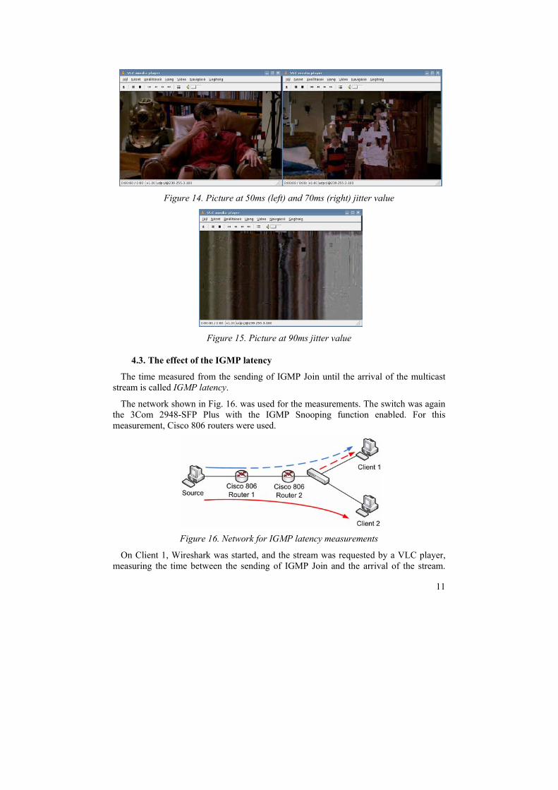
Figure 14. Picture at 50ms (left) and 70ms (right) jitter value
Figure 15. Picture at 90ms jitter value
4.3. The effect of the IGMP latency
The time measured from the sending of IGMP Join until the arrival of the multicast stream is called IGMP latency.
The network shown in Fig. 16. was used for the measurements. The switch was again the 3Com 2948-SFP Plus with the IGMP Snooping function enabled. For this measurement, Cisco 806 routers were used.
Figure 16. Network for IGMP latency measurements
On Client 1, Wireshark was started, and the stream was requested by a VLC player, measuring the time between the sending of IGMP Join and the arrival of the stream.

12
This process was repeated 18 times. As there were no other group members, the PIM tree was built and pruned every time when the VLC player running on Client 1 entered and left the group. A blues dashed line shows in Fig. 16. where the PIM tree had to be built and pruned.
After that, the measurements were repeated with the only difference that during the measurements the media stream was continuously played on Client 2. Continuous red line shows the stream for Client 2 and dashed red line shows the steam for Client 1 in Fig. 16. The IGMP latency results for the two cases are summarized on the diagram in Fig 17. The reason of the serious difference is evident: in the second case the stream was continuously flowing to Client 2, so the PIM tree was ready, only the IGMP Join was necessary.
In our small test network, the IGMP latency was so small in both cases, that it is invisible for the user. However, there is a significant difference between the IGMP latency of an empty and non empty group, so in a real-life-size network, the value of the IGMP latency can influence the QoE.
0
5
10
15
20
25
30
1 2 3 4 5 6 7 8 9 10 11 12 13 14 15 16 17 18
IGM
P la
tenc
y [m
s]
number of experiments
for empty group
for non empty group
Figure 17. IGMP latency measurement results
5. Conclusion We have introduced the essential protocols of IP multicast based IPTV systems. We
have shown why only the IP multicast based solution and not the unicast based one should be used for IPTV systems. We have demonstrated how the values of different Quality of Service parameters (packet loss, jitter, IGMP latency) effect to the Quality of Experience.
References
[1] ITU-T Recommendation Y.1901 (01/2009) – Requirements for the support of IPTV services (clause 3.2.15)
[2] Multimedia Research Group, Inc: "IPTV Global Forecast – 2010 to 2014" http://www.mrgco.com/iptv/gf1210.html
[3] Beau Williamson - Cisco Press Publications – Developing IP Multicast Networks