quality control tools - docs.esko.com · quality control tools serve any of these reasons: • to...
TRANSCRIPT

Automation Engine
Quality Control tools
12 - 2019
Automation Engine
Contents1. Concept and Overview............................................................................................................................. 5
2. Automation Engine Viewer......................................................................................................................62.1. Introduction....................................................................................................................................... 6
2.1.1. Supported File Types..............................................................................................................82.1.2. Starting the Viewer from the Pilot........................................................................................ 9
2.2. User Interface..................................................................................................................................102.2.1. Viewer Window Overview.....................................................................................................112.2.2. The File Selector................................................................................................................... 122.2.3. The Toolbar........................................................................................................................... 132.2.4. The (Top) Tools Panel........................................................................................................... 142.2.5. The Navigator Panel............................................................................................................. 152.2.6. The View Panel......................................................................................................................152.2.7. The Channels Panel..............................................................................................................162.2.8. The Info Panel.......................................................................................................................17
2.3. Working with Prepared View Data.................................................................................................172.3.1. Concept..................................................................................................................................172.3.2. Prepare for Viewer Task....................................................................................................... 182.3.3. Speed Up For Viewing.......................................................................................................... 202.3.4. Managing View Data.............................................................................................................20
2.4. How To............................................................................................................................................. 212.4.1. Zoom and Pan...................................................................................................................... 212.4.2. Change Clipping.................................................................................................................... 222.4.3. Inspect Channels...................................................................................................................232.4.4. Highlight Overprint............................................................................................................... 262.4.5. Measure Distances and Angles........................................................................................... 262.4.6. Measure Heights and Widths.............................................................................................. 282.4.7. Measure Color.......................................................................................................................292.4.8. Print........................................................................................................................................30
2.5. Working with Graphics................................................................................................................... 312.5.1. Checking Barcodes............................................................................................................... 312.5.2. Checking Braille.....................................................................................................................322.5.3. Seamless View.......................................................................................................................332.5.4. Compensating Distortion..................................................................................................... 362.5.5. Using Advanced View tools..................................................................................................37
2.6. Comparing Files...............................................................................................................................402.6.1. Intro........................................................................................................................................402.6.2. Difference View Modes and Options.................................................................................. 422.6.3. Difference Adjustments........................................................................................................44
ii

Contents
2.6.4. Matching Channels............................................................................................................... 442.6.5. Alignment Tools.................................................................................................................... 46
2.7. Working with Annotations..............................................................................................................492.8. Working with Multi-Page Files........................................................................................................50
2.8.1. Page List Panel......................................................................................................................502.8.2. Reader Spread View............................................................................................................. 512.8.3. Comparing Multi-Page Files................................................................................................. 52
2.9. Working with RIP data.................................................................................................................... 522.10. Keyboard Shortcuts.......................................................................................................................55
3. PitStop Preflight...................................................................................................................................... 573.1. Preflight Concept.............................................................................................................................573.2. The PitStop Profile Editor...............................................................................................................57
3.2.1. Setting Up the PitStop Profile Editor...................................................................................573.2.2. Smart Preflight: Using Variable Names in PitStop Profiles................................................59
3.3. Preflight with PitStop Task............................................................................................................. 603.3.1. Preflight Tab.......................................................................................................................... 613.3.2. Certified Tab.......................................................................................................................... 623.3.3. Report Tab............................................................................................................................. 633.3.4. Color Tab............................................................................................................................... 64
3.4. Verify Certification Task.................................................................................................................. 65
4. Global Vision Inspection Tasks............................................................................................................. 664.1. Introduction..................................................................................................................................... 664.2. Recurring Options in Global Vision Tasks..................................................................................... 664.3. Inspection Results as Annotations in Viewers..............................................................................69
4.3.1. Seeing Inspection Annotations in the WebCenter Viewer.................................................694.4. Inspect Artwork............................................................................................................................... 72
4.4.1. Concept and Workflow.........................................................................................................724.4.2. Compare Artwork Tab.......................................................................................................... 744.4.3. Report Tab............................................................................................................................. 75
4.5. Inspect Barcodes.............................................................................................................................764.5.1. Concept and Workflow.........................................................................................................764.5.2. Check Barcodes Tab............................................................................................................. 784.5.3. Report Tab............................................................................................................................. 82
4.6. Inspect Braille.................................................................................................................................. 834.6.1. Concept and Workflow.........................................................................................................834.6.2. Check Braille Tab.................................................................................................................. 844.6.3. Report Tab............................................................................................................................. 84
4.7. Inspect Spelling............................................................................................................................... 844.7.1. Concept and Workflow.........................................................................................................854.7.2. Check Spelling Tab................................................................................................................854.7.3. Report Tab............................................................................................................................. 86
4.8. Inspect Text......................................................................................................................................86
iii

Automation Engine
4.8.1. Concept and Workflow.........................................................................................................864.8.2. Compare Text Tab.................................................................................................................874.8.3. Report Tab............................................................................................................................. 87
4.9. Global Vision Profile Editor............................................................................................................ 874.9.1. Concept and Workflow.........................................................................................................874.9.2. Interface Overview................................................................................................................884.9.3. Prepare PDF Window............................................................................................................894.9.4. Comparing files.....................................................................................................................904.9.5. Inspecting Barcodes............................................................................................................. 944.9.6. Translating Braille............................................................................................................... 1004.9.7. Comparing Text...................................................................................................................1014.9.8. Checking Spelling................................................................................................................1034.9.9. Shortcut Keys...................................................................................................................... 104
5. Other QC Tasks......................................................................................................................................1055.1. Check Print Rules (PRC)................................................................................................................1055.2. Compare PDF................................................................................................................................ 105
iv
1Automation Engine
1. Concept and OverviewQuality Control tools serve any of these reasons:
• to prevent unnecessary work. For example preflighting incoming designs and refusing tostart prepress work on those that did not match a specific basic profile.
• to check the work you have done. Once you have started preparing, editing or outputtingfiles, there are many reasons to check if what you have done is as intended. Detailedinspection and comparing helps preventing many errors.
These tools can be interactive tools or Automation Engine tasks that report a status.
Learn more in
• Automation Engine Viewer on page 6
• PitStop Preflight on page 57
• Global Vision Inspection Tasks on page 66
• Other QC Tasks on page 105.
Note: This is not an overview of all Esko QC tools. This only describes the tools availablethrough Automation Engine.
5
2 Automation Engine
2. Automation Engine Viewer
2.1. Introduction
What is the Automation Engine Viewer?
The Automation Engine Viewer is a QC tool that enables you to view, check and comparegraphic production data.
The Viewer is started from within the Automation Engine Pilot, and can so be used by anyoneon a Mac or Windows computer in your network. It is not uncommon that staff from outsidethe prepress department like CSRs also use this tool.
Supporting many File Formats, Comparing and more
The Viewer supports many different file types: PDF, AI, ArtPro, images and even bitmap RIPdata. Learn more in Supported File Types on page 8.
You can compare files and analyse their differences, even when they have different file typesand even when they have a different size. Learn more in Comparing Files on page 40.
Other Esko Viewers
• The Esko Bitmap Viewer is similar to the Automation Engine Viewer, but only supports RIPdata. It is a standalone application and is only available on Windows.
• The Esko WebCenter Viewer is similar to the Automation Engine Viewer, with addedfunctionality for comments and approval and it also supports CAD and 3D files. This toolruns in a web browser..
Started from the Pilot
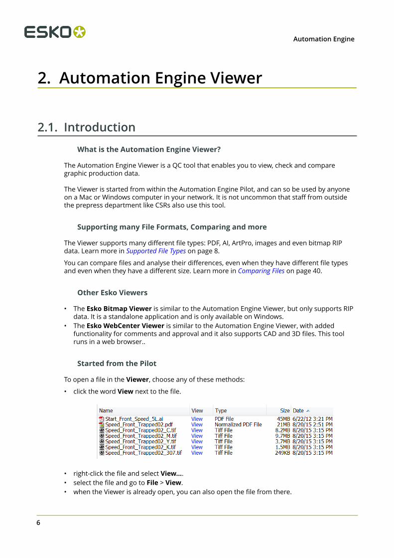
To open a file in the Viewer, choose any of these methods:
• click the word View next to the file.
• right-click the file and select View....• select the file and go to File > View.• when the Viewer is already open, you can also open the file from there.
6

2Automation Engine
Here 's an example of a file open for inspection in the Viewer:
The Concept of Prepared View Data
Foremost, a viewer tool must be reliable, it must show data in a correct way. The Viewer doesthis by using the same technology as the Esko editors and RIPs.
The next main challenge for any viewer is to combine these features:
• opening files fast, even when they are big.• being able to zoom in very deep, to show high detail, preferably also fast.
This is why you have a choice: to open files in the Viewer with or without first creatingPrepared View Data. Learn more in Working with Prepared View Data on page 17.
Limiting who can use deep zoom
When a user does not have the User Access Right for deep zoom, then
• you can only view file that has prepared view data.• your zoom is restricted.
This can help you avoid that a group of users, that does not need a too detailed view, wouldcause load problems on the server by accidental deep zooms.
7

2 Automation Engine
Learn more in Defining User Access Rights and Working with Prepared View Data on page 17.
2.1.1. Supported File Types
The Automation Engine Viewer supports these file types:
Graphic files, both with and without prepared View Data
Esko normalized data:
• Esko PDF
• Esko PDFPLA
Non-normalized graphic files:
• PDF• ArtPro• AI (when PDF compatible)• (E)PS. For Adobe Illustrator ‘EPS’ file types,
the same restrictions are valid as inPackEdge.
Images, both with and without prepared View Data
Supported:
• Esko CT
• Image EPS
• DCS/EPS• PSD• TIFF (< 600 ppi)• JPEG
Not Supported:
• images with Progressive Scan compression• images including linework• RGB images
This data can be viewed when you first usethe Image Import task.
RIP'ed data (Digital Film files), only with prepared View Data
• Esko LEN/LENX
• TIFF (> 600 ppi)
• DCS 2.0 (> 600 ppi)• VIEW (Imaging Engine print simulation files)
8

2Automation Engine
Note:
• To be able to open TIFF, LEN or print simulation files from Imaging Engine with theAutomation Engine Viewer, you can prepare view data for your files using either:
• the Make all output files ready for viewing option in your Imaging Engine task,
• the Prepare for Viewer task.
See the documentation of your Imaging Engine task (in the RIP'ing with Imaging Enginechapter) for more information.
• You cannot prepare LENX files for viewing with the Prepare for Viewer task. However, youcan either:
• use the Make all output files ready for viewing option in your Imaging Engine task,
• view them in the Bitmap Viewer (without preparation).
How different Graphic File Types are Streamed to the Viewer
The data shown in the Viewer are always pixels, referred to as 'View Data'. Usually, you needto zoom in quite deep to see these pixels appear. This is also because these pixels can be(re-)created on the fly: when you zoom in further, you are automatically shown a new set ofview data that again guarantees an optimal view.
The way that graphic files (non-images) become these pixel data is different for these groups offiles:
• Normalized files. These are automatically converted to view data the moment you openthem in the Viewer.
• PDF native, (E)PS and AI files are automatically normalized first before they are convertedto view data.
• ArtPro native files. Here you have the choice to also have them normalized first or to havethem shown in the Viewer using the same technology that visualizes them in ArtPro. Bothmethods are fully automatic.
• Prepared View Data. You can prepare this view data beforehand, so that when you openthe file in the Viewer, it opens instantly. Learn more about this important topic in Workingwith Prepared View Data on page 17.
When the view data was not prepared, it will be created automatically when you open thefile in the Viewer. The time this takes depends on the available power on the server and onthe size of the file (Horizontal -Vertical + the amount of inks).
Learn more about controlling these automatic normalization steps and more in the Viewer topicin the Configure panel (Tools > Configure > Viewer).
2.1.2. Starting the Viewer from the Pilot
Started from a Pilot
You can use as many Viewers as you have Pilot connections. Opening the Viewer does notallocate an extra Pilot connection.
9

2 Automation Engine
Note: You can even open multiple Viewers on the same workstation by opening a second Pilot(File > New window) and opening a file in the Viewer from there. Mind that this not requiredwhen comparing files. Learn more in Comparing Files on page 40.
Note: Opening the viewer itself takes some time, so do not close the viewer when regularlyviewing files.
"View" Statuses in the PilotThe View column can display any of these Viewer related statuses:
• (-). A dash indicates that the file is not viewable. For example TXT, XML, PAF, TCP, non-PDFoffice documents, etc.
• . The word 'View' in black indicates that the file is viewable when its file type asindicated by the file type extension corresponds with its real file type.
• . This indicates that the file can be viewed and that prepared view data areavailable. The file will open quickly. Learn more in Working with Prepared View Data on page17.
• . This indicates that the file can be viewed. Because no view data were prepared, theywill be created on the fly while opening the file in the Viewer.
• . This indicates that the file can not be viewed because it has prepared data thatare outdated. Solve this by deleting the view data or by preparing new view data. Learn howin Working with Prepared View Data on page 17.
Digital Film (RIP'ed) Files
To view digital film files in the Viewer, the situation is slightly different.
• For LEN files, you always need prepared view data.
• . This indicates that the file has up-to-date view data and can be viewed.• . This indicates that the file has no view data. It can therefore not be viewed
in the Viewer.• indicates that the .LEN files have view data, but that the view data is not in
sync with the original file and can therefore not be viewed.• For TIFF files, the behavior depends on the resolution of the file:
• A TIFF file with a resolution lower than 600 ppi can be viewed without having preparedview data.
• A TIFF file with a resolution higher than 600 ppi must have up-to-date prepared view datato be able to view it.
Note: The resolution is only checked after you clicked on . A warning will be shownwhen no view data are found when required.
Learn more in Working with RIP data on page 52.
2.2. User Interface
10
2Automation Engine
2.2.1. Viewer Window Overview
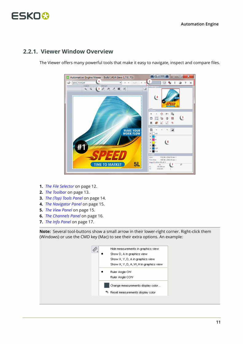
The Viewer offers many powerful tools that make it easy to navigate, inspect and compare files.
1. The File Selector on page 12.2. The Toolbar on page 13.3. The (Top) Tools Panel on page 14.4. The Navigator Panel on page 15.5. The View Panel on page 15.6. The Channels Panel on page 16.7. The Info Panel on page 17.
Note: Several tool-buttons show a small arrow in their lower-right corner. Right-click them(Windows) or use the CMD key (Mac) to see their extra options. An example:
11

2 Automation Engine
Tip: Hover the mouse over a button icon to read a short explanation (and often also a tip).
Tip: Hover the mouse on the right of the view area and drag the divider to give the left or rightpart more space. The resulting width of the tools panel will be remembered and restored foreach user.
Tip: You can open or collapse the tool panels by clicking on their small white arrow:
2.2.2. The File Selector
You can open files by clicking on in the Pilot. You can also open files by using the fileselector on board the Viewer:
• Click on to select a file from within a Job or Container.• Click on the drop-down icon to select a file from the list of recently viewed files.• Click on the arrows to scroll through the recently viewed files or to see other pages of an
open file.
Note: You can navigate through these files by using the keyboard shortcuts End, Home andPage Up / Down.
Limiting How Many Files you can Open
Each file that you have opened is a "file streaming session" from the Automation Engine serverto this Viewer client.
12

2Automation Engine
Attention: Mind that when you compare 2 files, that this is counted as 2 file streamingsessions.
To prevent that the server allocates too much computer memory to any Viewer, the followingtools serve to optimize that server memory:
• When you close the Viewer, all file streaming sessions to that Viewer are closed.• When, in the drop-down list, you click on ... Reset file list ..., all file streaming sessions are
also closed. Choose this when you want to continue using the Viewer with other files thanthose recently viewed.
• If there is no recent activity on a file already opened in the Viewer (zooming, measuring),then this file streaming session will be closed. Mind that this does not automatically closethe file in the Viewer.
• By default, an Automation Engine server only allows a maximum of 4 file streaming sessionsfor all connected Viewers. An administrator can change this number in the Server Admin webtool, in the item 'Processing Capabilities' of the Server Setup. When the maximum is reachedand an extra session is requested, the user will get a warning dialog that the maximum ofsessions was reached.
Note: An example: You have set a limit of 4 file streaming sessions.
• Pilot user 1 opens a file in his Viewer and compares it with another one. The total streamingsessions at this moment is 2.
• Then, users 2 and 3 also each open 1 file in their Viewer. The total streaming sessions at thismoment is 4.
• Then, user 2 gets up from his workstation to get a coffee but leaves the Viewer and the fileopen. He stays away 5 minutes. Before he is back, his file streaming session automaticallycloses, which brings the total streaming sessions at that moment back to 3.
• Then, user 3 also starts to compare his file with another one. The total streaming sessionsat this moment is 4.
• Then, user 2 is back at his workstation. His file is still open in the Viewer but the streamingsession for that file was already closed on the server a few minutes ago. He tries a zoom in.He gets an error that the maximum of 4 session is already reached.
2.2.3. The Toolbar
• The progress bar shows the progress of view data being streamed to your Viewer.Learn more in Working with Prepared View Data on page 17.
• Multi-page options (only shown when viewing a multi page file). Learn more inWorking with Multi-Page Files on page 50.
• The compare tool allows you to compare two files. Learn more in Comparing Files onpage 40.
• The annotations panel becomes available when your files has XFDF annotations. Learnmore in Working with Annotations on page 49.
13

2 Automation Engine
• The information button opens a dialog that shows the file's XMP metadata (the same one
as when you when you select a file in the Pilot and click in the Files view).
Note: Any barcodes mentioned in the XMP are of barcodes created with Esko tools. Thebarcode measurement tool on-board this Viewer can also detect and measure otherbarcodes.
• The print button allows to print what you see in the Viewer. Learn more in Print on page30.
• The help button opens the Viewer's online help in the local default browser.• The close button closes the file that is being viewed (not the whole Viewer).
2.2.4. The (Top) Tools Panel
The top tools panel offers the Viewer's most used tools. You can customize which tools you seeby right-clicking it and selecting or deselecting some tools.
Note: You can select a tool even when it is not currently available in the Viewer. For example,the Page list tool can be added to the top tools panel while working on a single page file forwhich this tool is not activated. This tool will then automatically appear in the panel the nexttime it can be used.
•Click on the right to hide or show all the right side panels (Tools, Navigator, View,Channels, Info).
•Click to show or hide the panel. Hiding the top tools panel automatically shows the rightside panels and vice-versa.
The top tools panel can offer the following tools:
Page List Tools
These are only shown when viewing multi-page files. Learn more in Working with Multi-Page Fileson page 50.
Inspect Tools•
Zoom tool. Right-click it to see extra options.•
Zoom out tool.•
Pan tool.
Select the tool and drag the image by holding down the left mouse button and moving themouse. You can temporarily switch to the Pan tool by holding down the space button.
Learn more in Zoom and Pan on page 21.
Measure Tools•
Ruler. Learn more in Measure Distances and Angles on page 26.•
Caliper. Learn more in Measure Heights and Widths on page 28.
14

2Automation Engine
• Densitometer. Learn more in Measure Color on page 29.
• Calculate screening and angle. Learn more in Working with RIP data on page 52.
• Inspect barcode. Learn more in Checking Barcodes on page 31.
• Inspect braille. Learn more in Checking Braille on page 32.
Compare Tools
The compare tools are automatically shown when you activated the Compare mode.
Learn more in Comparing Files on page 40.
2.2.5. The Navigator Panel
The Navigator panel shows a preview that indicates your current zoom and many otherviewing choices. Click on the preview to reposition your (same size) zoom area.
Tip: You can resize the navigator panel:
2.2.6. The View Panel
The View panel offers the following tools:
• Previous view: Shows you the previous view. Hold the Shift key to go to the first view.• Next view: Shows you the next view. Hold the Shift key to go to the last view.•
Rotate view tool. Hold down the Shift key when clicking to reverse the rotate direction.Or use the keyboard shortcuts Ctrl + Shift + '+' (90 degrees CW) and Ctrl + Shift + '-' (90degrees CCW).
• Mirror view: Mirrors the current view (Ctrl + M).•
Invert view: Inverts the current view (typically used when viewing only one channel).
• Background Color: Allows to change the background color of the image and/or thesurrounding viewer window. This can be useful when evaluating an image that will beprinted on a material that is not white. Setting a color for the image does not affect thechannels or any color measurements.
• Show margins (trim box): Shows the file’s trim box as a blue dashed line. Learn more inChange Clipping on page 22.
• View from back: Mirrors the current view and also reverses the sequence in which
the channels are shown. This is useful when viewing files that are printed on the back of atransparent material and therefore contain areas using opaque ink.
15
2 Automation Engine
• Set overprint highlight color: Highlights the overprints in a color of your choice. Learnmore in Highlight Overprint on page 26.
• Seamless view: Simulates a seamless layout. Learn more in Seamless View.
• Total Area Coverage: Shows the sum of all separation-densities at a certain point or
area in your document. Learn more in Using Advanced View tools on page 37.•
Flexo Plate: Shows a single separation as a flexo plate, by simulating both the colorand the missing too small percentages. Learn more in Using Advanced View tools on page37.
• Flexo Print: Shows the effect of highlight dot gain on the file. Learn more in Using
Advanced View tools on page 37.•
Break Out: Shows an area of a single separation where the percentage is lower thanthe first visible dot. Learn more in Using Advanced View tools on page 37.
• Registration Error: Shows a simulation of the file printed with registration errors.
Learn more in Using Advanced View tools on page 37.
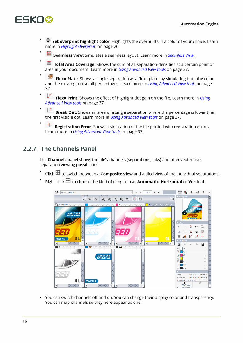
2.2.7. The Channels Panel
The Channels panel shows the file’s channels (separations, inks) and offers extensiveseparation viewing possibilities.
• Click to switch between a Composite view and a tiled view of the individual separations.• Right-click to choose the kind of tiling to use: Automatic, Horizontal or Vertical.
• You can switch channels off and on. You can change their display color and transparency.
You can map channels so they here appear as one.
16

2Automation Engine
Learn more in How to Inspect Channels.
2.2.8. The Info Panel
The Info panel displays:
• file information: Size and Trim Size• viewing conditions: current Magnification (zoom), mouse position, results from the ruler.
To change the units, click on one of the small triangles and select the unit (pt, mm, cm, inch).
2.3. Working with Prepared View Data
2.3.1. Concept
As mentioned when introducing the Viewer and also when explaining how different files arestreamed to the Viewer, preparing view data can be important to guarantee both speed anddetail when viewing files.
When you regularly experience significant delays when opening files, then consider preparingview data first. Files with prepared view data always open fast.
Zooming and panning will be faster on files with prepared view data. The load on the server isalso smaller when using prepared view data.
Note: When a (deep) zoom needs a resolution that is higher than the prepared one, the datafor that zoom area will automatically be streamed from the server. You may notice this delay(visible in the progress bar).
Tip: Ctrl-Shift-V displays the current view resolution.
Workflow
The Prepare For Viewer task creates prepared view data. Depending on your workflow, the sizeof the files and how consistent viewing delays are, you can choose to launch this task in one ormore of these ways:
• Ad hoc (manually), by selecting a file in the Pilot and launching the Prepare For Viewer task.When you often use this, consider making it a favorite ticket.
• Automatic, as part of workflow tickets. For example, when you often check RIP data inthe Viewer, then consider adding the Prepare For Viewer task as a workflow step after the
17

2 Automation Engine
RIP'ing step. Some users also add a Wait for Action (CheckPoint) task to create a QC step inthe users' To-Do list. An example:
• Automatic, for all files in a specific folder. For example, when you check all files arrivingin a specific folder, you can have that folder automatically launch the Prepare For Viewer taskon all incoming files. This way, you win time when opening those files in the viewer. Learnmore in Speed Up For Viewing on page 20.
Make sure your Prepared View Data is Up-To-Date
As mentioned in Starting the Viewer from the Pilot, you will not be able to view a file when ithas prepared view data that is outdated (older than the source file). This will be indicated by aspecific status in the View column: .
View data typically becomes outdated because the source file has a more recent modificationdate. So make sure you only create the prepared view data as a last step before checking it inthe viewer.
Attention: Prepared view data becomes useless when the source file was manuallymoved or renamed.
Note: When you move a source file with the Copy or Move File task, then the view data willfollow automatically.
Learn more in Managing View Data on page 20.
2.3.2. Prepare for Viewer Task
This task creates view data that will be used when you open its input file(s) in the AutomationEngine Viewer. The supported files types are those that the Viewer supports.
Attention: In many cases, you do not have to use this task before opening a file in theViewer. Learn more about this choice and workflows using prepared view data here.Find an introduction to the Automation Engine Viewer here.
18

2Automation Engine
• Resolution for non-images:
• Optimal: The task uses a smart algorithm to decide the optimal resolution for the viewdata (the one that offers the best balance insuring both speed and detail). The calculatedresolution is mentioned in the tasks 'details' and log file.
• Custom: Specify the resolution yourself.
Attention: We advise to only set a custom resolution in cases where you foundthat the optimal setting created a too small or too large set of view data.
• Anti-aliasing: This smooth-ens the staircase effect when images are generated from line-art objects.
• Merge Similar Inks: This merges inks that have a same name but have a different ruling orangle.
Attention: We strongly advise to enable this option when viewing ArtPro files orNormalized PDF files generated by ArtPro.
• Automatic grouping of input files into digital film sets: When digital film separations(RIP'ed files) are grouped into sets, they will open together in the Viewer and can so beinspected as a composite image. See some examples in Working with RIP data on page52.
• When this option is not selected, the list of task input files that the user manuallyselected or that a workflow created for this ticket will be grouped regardless of theirfile names. This is how you can for example get a composite view of these files (wherenot all have the same name before the suffix with the ink name):
• When this option is selected, the grouping is done automatically based on the filenames of the task input files. Using above example, you would then get 2 groups for
19
2 Automation Engine
composite viewing: one with only 3 separations from the Shrek files and one with oneseparation from the GreenMan file.
2.3.3. Speed Up For Viewing
As mentioned in Concept of View Data, you can have prepared view data created automaticallyfor all new files in a subfolder of a Job Folder.
Attention: Using this option will generate view data as soon as a file is written in thisfolder. And when a file in this folder is updated, its view data will be regenerated. Thiscan lead to overhead on the server when view data are generated that will not be used.Therefore, as a more optimal alternative, consider inserting a Prepare for Viewer taskat the right place in your workflows.
• To add this functionality to a folder, right-click any folder in a Job folder and select SpeedUp for Viewing. The folder will get a specific icon . From that moment on, AutomationEngine will automatically launch the Prepare for Viewer task on all new or modified files(that the Speed Up for Viewing task supports as input files).
The ticket of the Prepare for Viewer task that is used for these automatically launchedtasks is defined in the Configure tool.
Tip: When you are creating Jobs based on a template Job that has a subfolder with theattribute "Speed Up for Viewing", then this attribute will be inherited in the folder in thenew Job.
Note: When, in such a folder, a file is opened and being edited in Esko PackEdge or EskoPlato, you do not want to have view data re-created every time you click Save. That is whythe Prepare for Viewer task only starts and updates the view data once the file is closed inthe editor.
• To stop this functionality, right-click the folder and select Speed Up for Viewing to switch itoff again. This attribute is also removed automatically when the Job is removed, exported orarchived.
2.3.4. Managing View Data
The Prepare for Viewer Task creates the prepared view data in a hidden .view folder next to theinput file.
Warning: Accessing that hidden folder and deleting, moving or renaming this view datamanually will create Viewer errors.
The size of the view data depends on the chosen resolution and on the size and amount ofchannels of the source file.
Because this data is not small and temporary by nature, the following mechanisms help toclean up the prepared view data:
• When you demote a Job (by removing, exporting or archiving it), all view data in that jobfolder is automatically deleted.
• You can manually delete the (hidden) prepared view data, by:
20

2Automation Engine
• right-clicking a file and choosing Delete View Data. This removes the prepared view datafor that selected file only.
• right-clicking a folder and choosing Delete View Data. This removes the prepared viewdata for all files in that folder and its subfolders.
2.4. How To
This is an overview of frequently used tools that you can use on all types of files.
2.4.1. Zoom and Pan
Zooming•
Double click the zoom tool itself to zoom. If a selection was already made (for examplewhen measuring), the zoom will fit that selection to the window.
• Scroll the mouse to zoom in/out with the location of the mouse point as center.• For a marquee zoom, hold down the right button and drag the mouse.• Right-click (ctrl-click on a Mac) to see extra options:
• About the Zoom to 1:1 view:
• First use Set Monitor Resolution to inform this viewer about the current monitor. Thisvalue is saved per user per client computer. Learn more in this KB article.
• Then define what a click on Zoom to 1:1 view means. Choose to make it Zoom toreal size or choose to make it Zoom to 1:1 pixel to zoom to the resolution of the image,offering a lot of detail.
• Use and in the View panel to see a previous or next view.
Panning
Select the pan tool and drag the image by holding down the left mouse button and movingthe mouse. You can temporarily switch to the pan tool by holding down the space button.
While panning, you can still use these ways to zoom in/out with the mouse point as the center:
• double-click to zoom in• right-click to zoom out• scroll to zoom in/out.
21
2 Automation Engine
Keyboard Shortcuts
• No matter which tool you have selected, you can always use the right mouse button tozoom in:
• combine it with a right-click to zoom in by a factor 2.• combine it with holding down the Ctrl button to zoom out by a factor 2.
• Ctrl-'Arrow' pans the image 25% of the window size in the direction of the used arrow.
• Ctrl-Shift-Spacebar temporarily switches to the pan tool to allow one drag pan.
• In the View panel, when clicking and to see a previous or next view, hold Shift to gothe very first / last view.
• Photoshop style keyboard shortcuts:
• Ctrl-'+' zooms in with a factor 2.
• Ctrl-'-' zooms out with a factor 2.
• Ctrl-'0' fits the file in the window.
• PackEdge style keyboard shortcuts:
• F5 zooms in with a factor 2.
• F6 zooms out with a factor 2.
• F7 temporarily switches to the pan tool to allow one drag pan.
• F8 temporarily switches to the zoom tool to allow one drag zoom.
• F9 fits the file to fit in the window.
2.4.2. Change Clipping
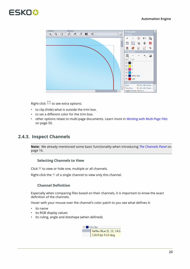
The trim box is often used as the basis for step and repeat of a one-up. It is good practice thatthe trim box corresponds to the bounding box of the die line.
Click to see the trim box as a blue dashed line. This allows you to check if the trim boxcorrectly fits the die line.
In below example, we see that the trim box fits on the 'CAD' line. Also notice the size values inthe Info panel:
22
2Automation Engine
Right-click to see extra options:
• to clip (hide) what is outside the trim box.• to set a different color for the trim box.• other options relate to multi-page documents. Learn more in Working with Multi-Page Files
on page 50.
2.4.3. Inspect Channels
Note: We already mentioned some basic functionality when introducing The Channels Panel onpage 16.
Selecting Channels to View
Click to view or hide one, multiple or all channels.
Right-click the of a single channel to view only this channel.
Channel Definition
Especially when comparing files based on their channels, it is important to know the exactdefinition of the channels.
Hover with your mouse over the channel's color patch to you see what defines it:
• its name• its RGB display values• its ruling, angle and dotshape (when defined).
23

2 Automation Engine
Changing the Appearance of a Channel
Double-click a channel to open its Channel Colors dialog.
The top part shows the Original Color Definition and is read-only.
The bottom part allows you to change the way the channel is displayed. This is for exampleuseful when the file contains a white separation because it will be printed on clear plastic. Tosee that separation better in the Viewer, you might want to display it as pink. To do this, setnew RGB values, or double click the color path and to pick a color.
Use the drop-down list to choose a color of another channel in the file. Select Opaque to makethe selected channel displayed opaque.
A channel of which you changed the display is marked with an asterisk (*)
Note: These display changes are not remembered the next time you open this file in theViewer.
Use the arrows at the bottom to browse through all channels, so that you can modifyseveral channels without reopening this dialog.
Use the button to reset the display to the channel's original color definition.
Changing how Single Channels are Displayed
Click to display a single channel in black instead of its own color.
Note: This setting is remembered the next time you open the Viewer.
A right-click on also offers to show single channel as black with show all effect. This viewuses black rather than a grey value for a display pixel that represents a partially covered area.This makes it easier to detect areas with small dots in RIP'ed files. An example:
24

2Automation Engine
Changing the Sequence of the Channels
Opaque inks cover previously printed inks, so the sequence when viewing these channels isalso important. You can change their display sequence by using the buttons. Moving achannel down means putting it later in the printing sequence, which would put it on top of theother channels.
Tip: You can also change the sequence by dragging the colored box of a channel to a differentposition.
Note: This display sequence does not have any influence on the actual printing sequence, onlythe display in the viewer is affected.
When you changed the channel sequence, click on to reset it to the original channelsequence. Right-click to choose what you are resetting (channel order, color definitions orboth).
Merging or Splitting the Display of Similar InksInks with a same name are by default shown as one same ink, even when they have a differentruling, angle or dot shape defined.
If you want to see such inks as separate channels, disable the setting Viewing Preferences > Merge Similar Inks in the Viewer item of the Configure panel. After a restart of the Viewer, youcan then click to unfold the channel and change view settings for the separate ones:
Learn more in Matching Channels on how to insist considering them as one channel whilecomparing.
Keyboard Shortcuts• Hold down Ctrl and press one of the number keys to select the corresponding channel and
deselect all other channels. 1 is the first channel, 2 is the second etc.
When you have more than 9 channels, use Ctrl-Shift-0, Ctrl-Shift-1,... , Ctrl-Shift-9 to selectchannels 10 to 19.
25

2 Automation Engine
• Ctrl-0 selects all channels.
• Ctrl-N selects a single channel. When multiple channels are selected, the first channel willbe selected. When a single channel is selected, the channel after the currently selected willbe selected, or when the currently selected is the last, the first will be selected.
2.4.4. Highlight Overprint
Click to get a clear indication of all areas where two or more active channels areoverlapping (keyboard shortcut Ctrl-H).
This tool is useful when checking trapping:
To change the highlight color, click the Overprint Highlight color patch and choose a customone.
2.4.5. Measure Distances and Angles
To measure between two points:
26
2Automation Engine
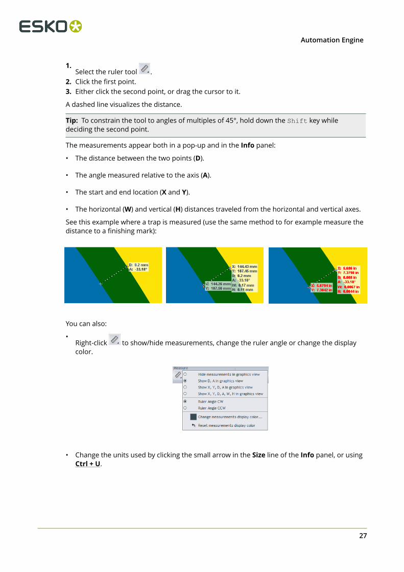
1.Select the ruler tool .
2. Click the first point.3. Either click the second point, or drag the cursor to it.
A dashed line visualizes the distance.
Tip: To constrain the tool to angles of multiples of 45°, hold down the Shift key whiledeciding the second point.
The measurements appear both in a pop-up and in the Info panel:
• The distance between the two points (D).
• The angle measured relative to the axis (A).
• The start and end location (X and Y).
• The horizontal (W) and vertical (H) distances traveled from the horizontal and vertical axes.
See this example where a trap is measured (use the same method to for example measure thedistance to a finishing mark):
You can also:
•Right-click to show/hide measurements, change the ruler angle or change the displaycolor.
• Change the units used by clicking the small arrow in the Size line of the Info panel, or usingCtrl + U.
27
2 Automation Engine
Tip: You can combine the ruler tool with other view tools. For example: click on a point, thenchange the view (by zooming out, panning or turning back to a previous view), and then clickthe second measuring point.
2.4.6. Measure Heights and Widths
Use the caliper tool to measure the height or width of multiple, typically aligned, (text)objects. You can measure freely or you can use fixed preset sizes.
Click to activate it and start measuring using the last chosen style.
Right-click the tool to choose a style or to manage fixed presets.
• Free Selection (default)
• Click on a first point of measurement.• Move or drag to the second point.
Tip: You can use all zoom and scroll functions while you are navigating to the first orsecond point.
• Click on the second point. While moving the mouse, a pop-up displays the current gapsize and the X / Y coordinate.
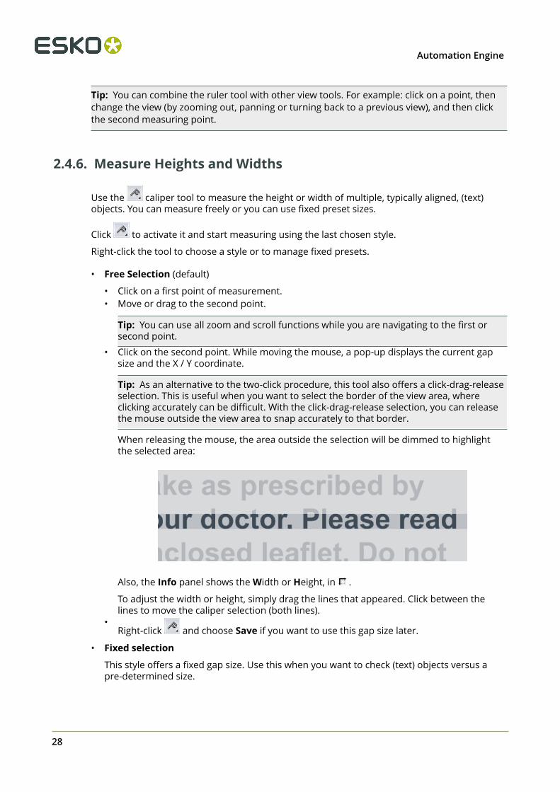
Tip: As an alternative to the two-click procedure, this tool also offers a click-drag-releaseselection. This is useful when you want to select the border of the view area, whereclicking accurately can be difficult. With the click-drag-release selection, you can releasethe mouse outside the view area to snap accurately to that border.
When releasing the mouse, the area outside the selection will be dimmed to highlightthe selected area:
Also, the Info panel shows the Width or Height, in .
To adjust the width or height, simply drag the lines that appeared. Click between thelines to move the caliper selection (both lines).
•Right-click and choose Save if you want to use this gap size later.
• Fixed selection
This style offers a fixed gap size. Use this when you want to check (text) objects versus apre-determined size.
28

2Automation Engine
•Right-click and choose Change if you see no list of gap sizes yet.
• Use the dialog to Add or Delete gap sizes. Define their orientation as either Height orWidth. Click OK to close.
• Start using the selected gap size.
Tip: The caliper selection will disappear if you switch to another tool. You can also clearit explicitly by choosing Clear in the tool's right-click menu.
2.4.7. Measure Color
Select the densitometer tool and either click a point in your file, or click and drag arectangle, to measure the color.
The measured dot percentage in that point or area are shown in the Channels panel, and thelocation in the Info panel.
Tip: Double-click the densitometer to make a measurement based on the current selection or,when no selection is active, based on the current view.
By default, the measured densities are also shown in a pop-up near the location you measured(right-click the tool to hide or show this pop-up).
In below example, you might be interested in the Total Area Coverage of that specific area (asshown in the result for 'All' channels: 334%):
Note: There is a dedicated tool to check TAC. Learn more in Total Area Coverage on page 38.
When viewing Digital Film files (RIP data), you can change the units in the pop-up. Click thesmall arrow next to the current unit and select your preferred units.
29
2 Automation Engine
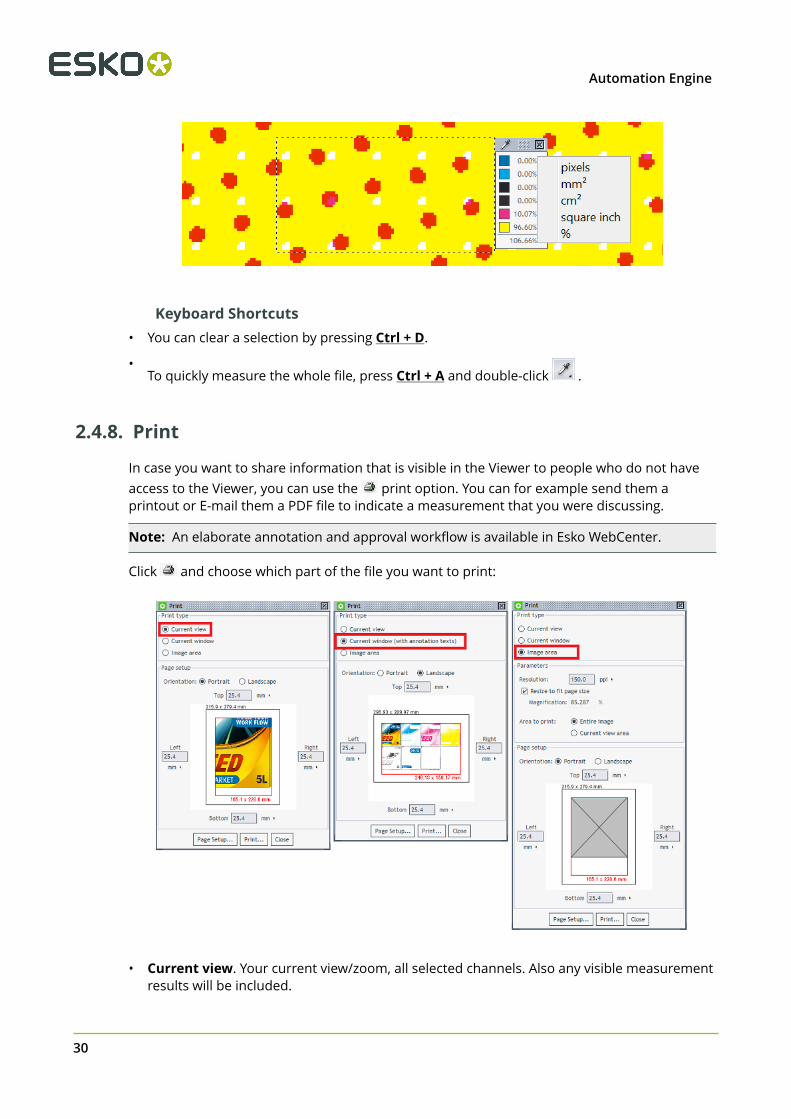
Keyboard Shortcuts• You can clear a selection by pressing Ctrl + D.
•To quickly measure the whole file, press Ctrl + A and double-click .
2.4.8. Print
In case you want to share information that is visible in the Viewer to people who do not haveaccess to the Viewer, you can use the print option. You can for example send them aprintout or E-mail them a PDF file to indicate a measurement that you were discussing.
Note: An elaborate annotation and approval workflow is available in Esko WebCenter.
Click and choose which part of the file you want to print:
• Current view. Your current view/zoom, all selected channels. Also any visible measurementresults will be included.
30
2Automation Engine
• Current window. Whatever the Viewer window shows will be printed (possibly extended tofill the chosen page size). Also, any annotations will be included too.
• Image area. By default this is the whole file, no matter what the current view or zoom is.You still have extra parameters to define the area and to choose all or only the selectedchannels.
2.5. Working with Graphics
2.5.1. Checking Barcodes
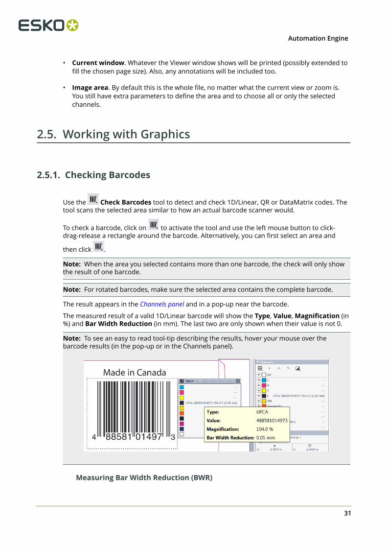
Use the Check Barcodes tool to detect and check 1D/Linear, QR or DataMatrix codes. Thetool scans the selected area similar to how an actual barcode scanner would.
To check a barcode, click on to activate the tool and use the left mouse button to click-drag-release a rectangle around the barcode. Alternatively, you can first select an area and
then click .
Note: When the area you selected contains more than one barcode, the check will only showthe result of one barcode.
Note: For rotated barcodes, make sure the selected area contains the complete barcode.
The result appears in the Channels panel and in a pop-up near the barcode.
The measured result of a valid 1D/Linear barcode will show the Type, Value, Magnification (in%) and Bar Width Reduction (in mm). The last two are only shown when their value is not 0.
Note: To see an easy to read tool-tip describing the results, hover your mouse over thebarcode results (in the pop-up or in the Channels panel).
Measuring Bar Width Reduction (BWR)
31

2 Automation Engine
The measured BWR can be slightly different from what was entered when creating the barcode(in PackEdge, ArtPro or Adobe Illustrator (DeskPack). This is due to the resolution of the pixeldata that are being measured. Typically, a difference in width of 1 pixel causes a different resultin the Automation Engine Viewer or when using the Inspect Barcodes task.
This table shows the maximum deviation that can occur when measuring BWR:
Automation Engine Viewer Inspect Barcodes task
Without preparedview data
Prepared viewdata at 600 ppi
600 ppi 300 ppi
Max. Dev. (mm) 0.0300 0.0125 0.0100 0.0110
Note on reading Pharma codes
A Pharma barcode can be read in 2 possible directions.
When using this ‘Inspect Barcodes’ tool, it will show 2 values. Next to those values, an arrowindicates which direction was used to measure:
When a Pharma barcode is placed vertically,
• 'Top to bottom' equals 'right to left' when you would rotate the barcode 90 degrees CW.• 'Bottom to top' equals 'left to right' when you would rotate the barcode 90 degrees CW.
2.5.2. Checking Braille
Use the Check Braille tool to detect and translate braille from a selected language.
To check braille, click to activate the tool and use the left mouse button to click-drag-release a rectangle around the braille. Alternatively, you can first select an area and then click
.
32

2Automation Engine
The result appears in the Channels panel and in a pop-up near the braille.
When the braille contains multiple lines of text, the result will add a line number in squarebrackets before the text of each line.
When the selected area contains more than one block of braille, the results from all blocks willbe shown. An extra number will indicate the number of the block. The tool-tip also helps tovisualise this:
Language selectionBraille is written in a specific language. The translation therefore depends on which languagethe braille was originally coded in.
Right-click to select that language. You can choose to do this before or after you measuredthe braille. By default, English is selected.
2.5.3. Seamless View
Click Seamless view to check how well the file is suited for seamless printing.
By default, the seamless repetition is made around the trim box. When no trim box is defined(in the XMP metadata), the repetition will be made around the image’s boundaries.
33

2 Automation Engine
Activating this tool immediately shows a seamless repetition and offers these extra options:
• to decide the color of the seamless guide lines.
• to show or hide the seamless guide lines (keyboard shortcut Ctrl-R).
• to set the seamless trim box to the current selection. Learn more below.
• to reset the seamless trim box. Learn more below.
• to enable a seamless view after you first manually defined an overlap zone. Learn morebelow.
Checking if Screening is SeamlessWhen viewing screened data in this view, you can then zoom in to the relevant edges and checkif the file will print seamless:
34

2Automation Engine
Tip: You can use Seamless Screening in Imaging Engine to stretch the screen slightly so the dotsfit together at the edges.
Tip: When the guide lines disturb the view, click to hide them.
Learn more about viewing RIP'ed data in Working with RIP data on page 52.
Making the Seamless Crop Area Smaller
To select a different area for the seamless repetition (smaller than the trim box), use the seamless crop tool.
This tool has two functions:
• When no selection is active, a click on sets the current selection to be identical to thecurrent seamless crop area. Initially this will be the trim box, or, when none is defined, theimage boundary. You can now modify the selection to the wished trim area by dragging thecorners or sides. When done modifying, click again to confirm. A new seamless view iscalculated and shown.
• When you already have an active selection (a rectangle in a black dashed line) that isdifferent from the current seamless crop area, a click on sets the seamless crop area tobe identical to that selection.
To revert to the original seamless crop area, click .
Seamless View with an Overlap
The Overlap option helps to check files that do not have a rectangular clipping but a die
line with a specific shape. Combined with , you use the tool to define the overlap that youneed to see the effect of a seamless print.
An example:
The file we are viewing is a label that has already been repeated for a narrow-web layout. Thestaggered cut type repetition makes it necessary to define an overlap:
35
2 Automation Engine
Follow these steps to use an overlap in order to reach a seamless view:
1. Open the file and click to activate seamless view (based on the trim box). The view is notseamless yet (as in the left side of above example).
2. Click on to enable working with an overlap.3. Click on to enable moving guide line(s).4. With your mouse, approach the guide line(s) that you want to drag and move (maybe zoom
in as well).5. When the mouse cursor changes into a double arrow, define the overlap by dragging that
guide line to the wanted new position (in an example like the above, drag the top and/orbottom guide line inwards).
6. Click on again to confirm that this is the new crop area you want to see in a seamlessview. A new view is calculated that now should look seamless (as in the right side of aboveexample).
Keyboard Shortcuts
• Ctrl-R toggles the seamless guide lines on and off.
• Ctrl-D clears the current selection.
2.5.4. Compensating Distortion
What is Distortion?Distortion in graphic files is done to pre-compensate the distortion that will happen whenit is printed, for example in flexo printing. Such distortion is typically done when RIP'ing, thelast step before printing, but in some workflows the digital file is already distorted (or scaled)before the RIP'ing.
The Viewer uses the file’s XMP metadata to detect if and by how much the file was distorted (Vand/or H).
The Compensate Distortion Tool
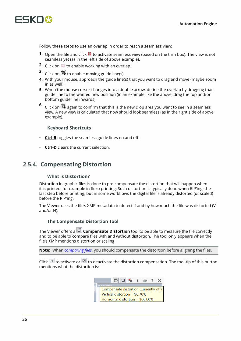
The Viewer offers a Compensate Distortion tool to be able to measure the file correctlyand to be able to compare files with and without distortion. The tool only appears when thefile's XMP mentions distortion or scaling.
Note: When comparing files, you should compensate the distortion before aligning the files.
Click to activate or to deactivate the distortion compensation. The tool-tip of this buttonmentions what the distortion is:
36

2Automation Engine
When distortion compensation is active, the size and resolution are also adjusted in the Infopanel. Here is an example where the file has a vertical distortion of 96.70% :
Compensating Scale and/or DistortionIn some workflows scaling is done instead of distortion. The viewer allows to compensate the(XMP) scaling in the same way as it does for distortion.
When you open a file where the XMP mentions both distortion and scaling, right-click tochoose what you want to have compensated: distortion, scaling or both.
2.5.5. Using Advanced View tools
Showing or Hiding Advanced View ToolsRight-click the background of the View panel to show or hide these Advanced View Tools.
Enabling Flexo Tools for Screened Data too
Because the 3 Flexo related tools are specifically designed for non-screened data,they are by default disabled for screened data (their buttons are greyed out).
However, these Flexo Tools can be useful for screened data too, but only if you use them at azoom ratio where the individual screen dots are not visible. Right-click the background of theView panel and select the option to enable them for screened data too.
Attention: In these tools, when entering (percentage) decimal values, use a point, nota comma.
37
2 Automation Engine
Total Area Coverage
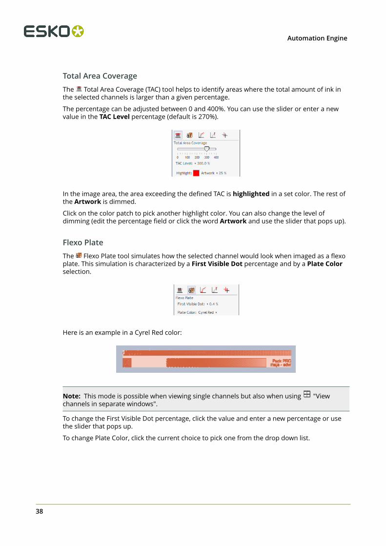
The Total Area Coverage (TAC) tool helps to identify areas where the total amount of ink inthe selected channels is larger than a given percentage.
The percentage can be adjusted between 0 and 400%. You can use the slider or enter a newvalue in the TAC Level percentage (default is 270%).
In the image area, the area exceeding the defined TAC is highlighted in a set color. The rest ofthe Artwork is dimmed.
Click on the color patch to pick another highlight color. You can also change the level ofdimming (edit the percentage field or click the word Artwork and use the slider that pops up).
Flexo Plate
The Flexo Plate tool simulates how the selected channel would look when imaged as a flexoplate. This simulation is characterized by a First Visible Dot percentage and by a Plate Colorselection.
Here is an example in a Cyrel Red color:
Note: This mode is possible when viewing single channels but also when using "Viewchannels in separate windows".
To change the First Visible Dot percentage, click the value and enter a new percentage or usethe slider that pops up.
To change Plate Color, click the current choice to pick one from the drop down list.
38
2Automation Engine
Flexo Print
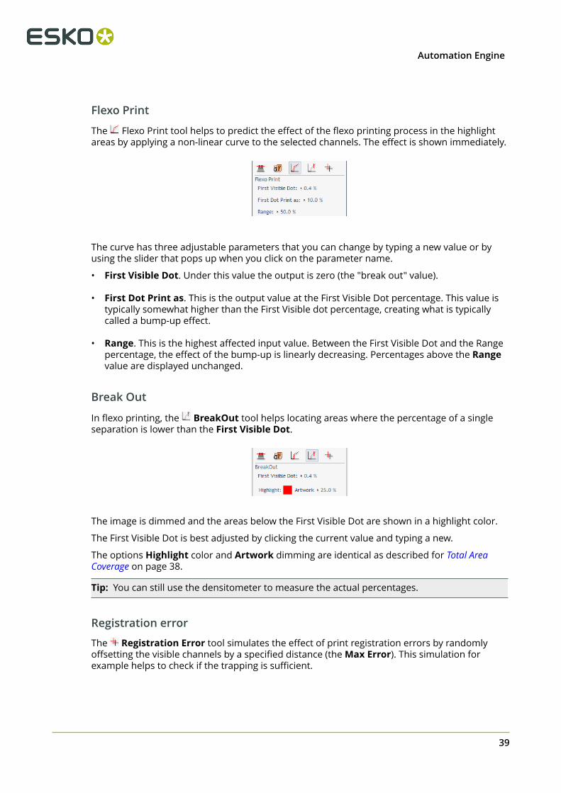
The Flexo Print tool helps to predict the effect of the flexo printing process in the highlightareas by applying a non-linear curve to the selected channels. The effect is shown immediately.
The curve has three adjustable parameters that you can change by typing a new value or byusing the slider that pops up when you click on the parameter name.
• First Visible Dot. Under this value the output is zero (the "break out" value).
• First Dot Print as. This is the output value at the First Visible Dot percentage. This value istypically somewhat higher than the First Visible dot percentage, creating what is typicallycalled a bump-up effect.
• Range. This is the highest affected input value. Between the First Visible Dot and the Rangepercentage, the effect of the bump-up is linearly decreasing. Percentages above the Rangevalue are displayed unchanged.
Break Out
In flexo printing, the BreakOut tool helps locating areas where the percentage of a singleseparation is lower than the First Visible Dot.
The image is dimmed and the areas below the First Visible Dot are shown in a highlight color.
The First Visible Dot is best adjusted by clicking the current value and typing a new.
The options Highlight color and Artwork dimming are identical as described for Total AreaCoverage on page 38.
Tip: You can still use the densitometer to measure the actual percentages.
Registration error
The Registration Error tool simulates the effect of print registration errors by randomlyoffsetting the visible channels by a specified distance (the Max Error). This simulation forexample helps to check if the trapping is sufficient.
39

2 Automation Engine
The effect is shown immediately. Here is an example:
When you change the value of the Max Error, click Try Again to see the new effect. Thisallows using zoom and pan tools to visually inspect the effects of a given registration error ondifferent parts of the design.
Note: The tool randomly shifts all channels with the Max Error distance, but all under arandom angle.
If you want to see another random simulation, click Try Again.
2.6. Comparing Files
2.6.1. Intro
The viewer allows to compare files and inspect their differences.
To compare two files, open a first file ("Current"), then click the Compare button andchoose a second file ("Reference") from the dialog.
In compare mode, an extra toolbar offers to rotate, mirror or invert the reference file or alignthe 2 files.
The extra buttons in the Channels panel (and also the Top Tools bar) offer several ways to viewthe differences.
40

2Automation Engine
Tip: While comparing, you can still use other tools like changing view windows, zooming,panning, rotating, measuring etc.
You can stop comparing and close the reference file by clicking again.
Two Ways of Comparing
The Viewer offers 2 comparison modes:
• Compare Channels. This is the default mode. It shows differences that it finds in channelswith identical definitions. Learn more here.
• Compare HSV. This mode compares colors. Learn more here.
File Types and Precision
You can compare files that have a different file type. For example comparing an AI design withits final production PDF or comparing that one-up PDF with its step & repeat version, or evenwith its RIP'ed version.
Some file types require a conversion before they can be shown in the viewer. Theseconversions can cause small, insignificant differences. Here are some general guidelinesregarding differences in different file types:
• Be aware of hidden file conversions as described in How different Graphic File Types areStreamed to the Viewer on page 9.
• Do not compare prepared with non-prepared files. Especially the 'Compare Channels'mode will detect differences due to the different sets of pixels in the Viewer.
41
2 Automation Engine
• When you need to compare an Esko normalized file with its (original) non-normalizedversion, you can set up a workflow where you always keep the first file version right afterthe normalization, before you start to edit it, and then compare that file with the (final)edited version.
Note: The tool to Calculate Screening and Angle ( ) is disabled when you are comparingfiles and at least one of the files is not RIP data (a PDF for example).
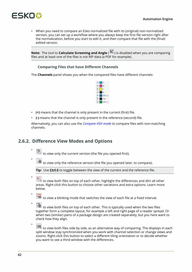
Comparing Files that have Different Channels
The Channels panel shows you when the compared files have different channels:
• (+) means that the channel is only present in the current (first) file.
• (-) means that the channel is only present in the reference (second) file.
Alternatively, you can also use the Compare HSV mode to compare files with non-matchingchannels.
2.6.2. Difference View Modes and Options
• to view only the current version (the file you opened first).
• to view only the reference version (the file you opened later, to compare).
Tip: Use Ctrl-S to toggle between the view of the current and the reference file.
• to view both files on top of each other, highlight the differences and dim all other
areas. Right-click this button to choose other variations and extra options. Learn morebelow.
• to view a blinking mode that switches the view of each file at a fixed interval.
• to view both files on top of each other. This is typically used when the two files
together form a complete layout, for example a left and right page of a reader spread. Orwhen two (similar) parts of a package design are created separately, but you here want tocheck how they align.
• to view both files side by side, as an alternative way of comparing. The displays in each
split window stay synchronized when you work with channel selection or change views andzooms. Right-click this button to select a different tiling orientation or to decide whetheryou want to see a third window with the differences.
42
2Automation Engine
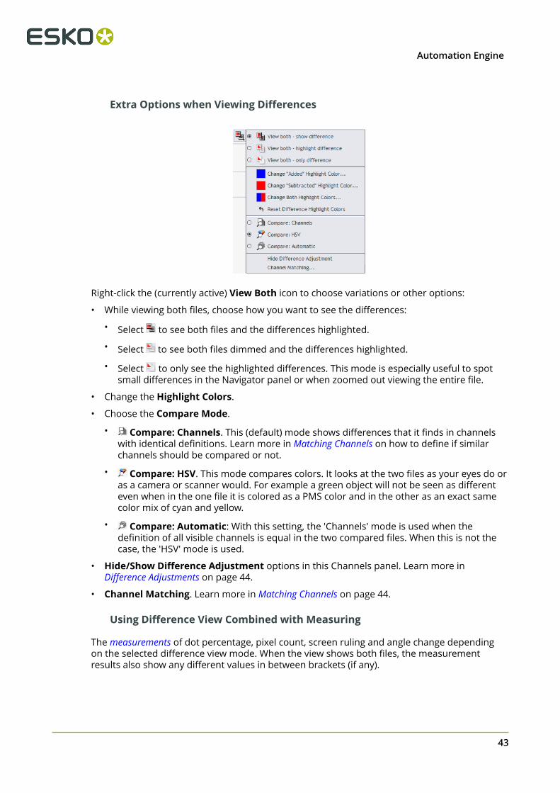
Extra Options when Viewing Differences
Right-click the (currently active) View Both icon to choose variations or other options:
• While viewing both files, choose how you want to see the differences:
• Select to see both files and the differences highlighted.
• Select to see both files dimmed and the differences highlighted.
• Select to only see the highlighted differences. This mode is especially useful to spotsmall differences in the Navigator panel or when zoomed out viewing the entire file.
• Change the Highlight Colors.
• Choose the Compare Mode.
• Compare: Channels. This (default) mode shows differences that it finds in channelswith identical definitions. Learn more in Matching Channels on how to define if similarchannels should be compared or not.
• Compare: HSV. This mode compares colors. It looks at the two files as your eyes do oras a camera or scanner would. For example a green object will not be seen as differenteven when in the one file it is colored as a PMS color and in the other as an exact samecolor mix of cyan and yellow.
• Compare: Automatic: With this setting, the 'Channels' mode is used when thedefinition of all visible channels is equal in the two compared files. When this is not thecase, the 'HSV' mode is used.
• Hide/Show Difference Adjustment options in this Channels panel. Learn more inDifference Adjustments on page 44.
• Channel Matching. Learn more in Matching Channels on page 44.
Using Difference View Combined with Measuring
The measurements of dot percentage, pixel count, screen ruling and angle change dependingon the selected difference view mode. When the view shows both files, the measurementresults also show any different values in between brackets (if any).
43

2 Automation Engine
2.6.3. Difference Adjustments
Compare ModesThese modes are described above in Extra Options when Viewing Differences on page 43.
Difference ThresholdWhen comparing files that are not perfectly aligned or that have minor tonal differences, youcan specify a threshold on when a difference should be highlighted. This allows you to make adistinction between minor and major differences.
Type a percentage in Difference Threshold or use the slider that appears when you click onthe small arrow.
Here is an example where the lines that are due to a file conversion disappear when changingthe threshold to 5:
2.6.4. Matching Channels
Sometimes you may want to compare channels that do not have a same channel definition.For example:
44
2Automation Engine
• A channel that is actually the same but has a different display color in the 2 compared files.For example an ink 'Cut' that was defined to look green in one file and pink in the other.
• Channels that are related but have different ink names in the 2 files. For example '123'and 'Pantone 123 C'.
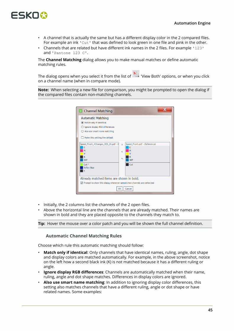
The Channel Matching dialog allows you to make manual matches or define automaticmatching rules.
The dialog opens when you select it from the list of 'View Both' options, or when you clickon a channel name (when in compare mode).
Note: When selecting a new file for comparison, you might be prompted to open the dialog ifthe compared files contain non-matching channels.
• Initially, the 2 columns list the channels of the 2 open files.• Above the horizontal line are the channels that are already matched. Their names are
shown in bold and they are placed opposite to the channels they match to.
Tip: Hover the mouse over a color patch and you will be shown the full channel definition.
Automatic Channel Matching Rules
Choose which rule this automatic matching should follow:
• Match only if identical: Only channels that have identical names, ruling, angle, dot shapeand display colors are matched automatically. For example, in the above screenshot, noticeon the left how a second black ink (K) is not matched because it has a different ruling orangle.
• Ignore display RGB differences: Channels are automatically matched when their name,ruling, angle and dot shape matches. Differences in display colors are ignored.
• Also use smart name matching: In addition to ignoring display color differences, thissetting also matches channels that have a different ruling, angle or dot shape or haverelated names. Some examples:
45

2 Automation Engine
• An ink 'K' at 120 LPI will match to the other file's ink 'K' at 66 LPI.
• Inks with names that only differ in use of upper and lower case. For example: 'KiwiGreen' will mach to 'Kiwi green'.
• Inks with names that only differ in color book specification. For example: '660' willmatch to 'Pantone 660 C' and 'Cyan' will match to 'Process Cyan'.
• Inks with names that are known abbreviations of each other. For example 'C' and'Cyan'.
The effect of the chosen rule is immediately shown in the two columns.
Note: Select Make this setting the default when you not only want to apply this rule to thecurrent file, but during every comparison (without need to open this dialog).
Manually Matching Channels
When the automatic matching does not yet match all the channels that you want to comparedirectly, you can also manually match channels.
To do this, select the source and the target channel (one in each column) and then press or ,depending on which way you want the mapping to go.
Channels that changed are marked with an asterisk (*).
To revert a channel to its original definition, select it and click .
2.6.5. Alignment Tools
Alignment tools help you compare files with different sizes, or files with the same size wherethe content is offset differently from the trim box.
46

2Automation Engine
You can align such files by using these tools:
• Rotating, mirroring or inverting the reference file might already help to align.
• Click to choose any of these methods:
• To align both files on a specific corner.• To align both files with the help of the ruler tool. Learn more in Align from Ruler, Auto Align
from Ruler and Auto Align.• Click for a quick access to Auto Align.• Click to align based on their margins (trim box). When no trim box information is
included in the file's XMP, the file's boundary is used instead.• Use to indicate an offset manually.• Click to use the alignment settings for other pages in this file.
Align from RulerYou can use the ruler tool to indicate a point in each file that you want to align.
1. While viewing the differences, zoom in on an area where you will indicate two alignmentpoints that represent the same position in their file, for example a corner of an object.
2.Click to view only the reference file.
3. Click and select Align From Ruler from the list. A pop-up dialog will remind you howto proceed ; click OK to close it.
When your mouse cursor is at this moment showing a zoom or pan tool, click toturn it into a + cursor.
4. In this reference file, click to indicate the first alignment point.For example you can select a corner (shown here in a red circle):
47

2 Automation Engine
5.
Click or use Ctrl + S to switch to the current file. Use shortcuts for a one-time zoom orpan.
6. Indicate the corresponding point, that will now be in a different position.In our example, that same corner (shown here in a blue circle):
7. Click again to align the files according the alignment points indicated.
Switch back to the "View Both" mode to see how well this worked:
Note:
Depending on how precisely you defined the second point, you may have to zoom in andrepeat the steps above to align your files with more precision.
Alternatively, you can align your files more automatically using the Auto Align from Ruler orAuto Align tools.
Auto Align from Ruler
Auto Align from Ruler is used the same way as the Align from Ruler tool, but is moreaccurate at a high resolution.
When the data surrounding the alignment points match, the tool will be able to increase thealignment precision (and have a good alignment with fewer iterations).
Auto AlignAuto Align (Ctrl + L) does not use the ruler, but uses the currently visible view of the twocompared images to attempt an automatic alignment.
48

2Automation Engine
Using this tool repeatedly with one or more zoom-ins can be a very easy and fast way to aligntwo files.
For convenience, a separate tool button is available to perform an automatic alignment
without having to open the alignment pop-up menu.
When a ruler selection is active, clicking performs an Auto Align from Ruler, otherwise itdoes an Auto Align based on the current view.
2.7. Working with Annotations
Based on XFDF
The five "Inspection" tasks generate XFDF files that contain inspection annotations. These XFDFfiles are written in a hidden subfolder.
When viewing a file in the Automation Engine Viewer that has such XFDF data, the Annotation list button appears in the tool bar.
Click to see the file's annotations in the Annotation list panel.
The Annotation List Panel
• Click its toolbar icons to choose the type of annotations that you want to see detailed. Tool-tips mention their type. They are greyed out when no such annotations are available.
• Each annotation is assigned a specific number and color.• Select an annotation in the panel to see it's colored rectangle highlighted in the main
window. When Fit view to selected annotation is selected, the window will also zoom in tothat object or found difference.
• For multi-page files, the panel shows the annotations of all pages.
49

2 Automation Engine
• Annotations can show as outdated when the modification date of the viewed file is newerthan the date when the inspection task was run on that file (modification dates of anyreferenced files from the input file are not taken into account).
Learn more about the content of the annotations in the pages on their respective task: InspectBarcodes, Inspect Braille, Inspect Spelling, Inspect Artwork, Inspect Text.
Caution: When you move or copy the input file using the Copy or Move File task or thePublish on WebCenter task, the hidden folder with the XFDF file will be moved as well.However, when you move the input file with other tools, Automation Engine is notaware and the XFDF file will not move along and will so not be found from the new filelocation.
2.8. Working with Multi-Page Files
When opening a multi-page file, extra viewing tools become available:
2.8.1. Page List Panel
Click to open the Page List panel. Right-click to define the size of the thumbnails.
Click on a thumbnail to see that page in the main window.
50

2Automation Engine
Note: The Top Tools bar also offers , a tool to mark pages. However this tool is only usefulin the Esko WebCenter Viewers.
Keyboard Shortcuts
• End. Go to last page (last file when multiple files open)• Home. Go to first page (first file when multiple files open).• Page Down. Go to next page.• Page Up. Go to previous page.
2.8.2. Reader Spread View
Click to enable a Reader Spread view, showing pairs of pages as they will appear in the finalprinted result.
Attention: The compare mode is disabled while reader spread view is enabled (andvisa versa).
A reader spread shows two pages stitched together on their trim boxes. First and last pagesare shown with an empty (white) area next to it.
Clicking now shows the previous / next reader spread.
In reader spread view, one page is the active page. That page has its page number highlighted
in the Page list panel and, when clicking , its trim box is shown.
In the View panel, right-click to use these page related options:
51

2 Automation Engine
• choose to show the margins (trim box) of both pages when in reader spread view.• choose to only clip on margins in reader spread view.• choose to show the margins of the two pages in different colors.
2.8.3. Comparing Multi-Page Files
When comparing two multi-page files, the viewer presents an option panel:
• Compare to page. Select which page in the reference file you want to compare with thecurrent page in the current file. By default, this is the page with the same page number (ifthis page exists).
• Decide which (other) pages should be compared:
• Current page only.
• Current and following pages. As long as there are pages in both files, it continuescomparing their next pages.
• All pages. Same as above, but now also compares the pages before the current one, ifany.
2.9. Working with RIP data
A Composite View of RIP'ed Separations
52
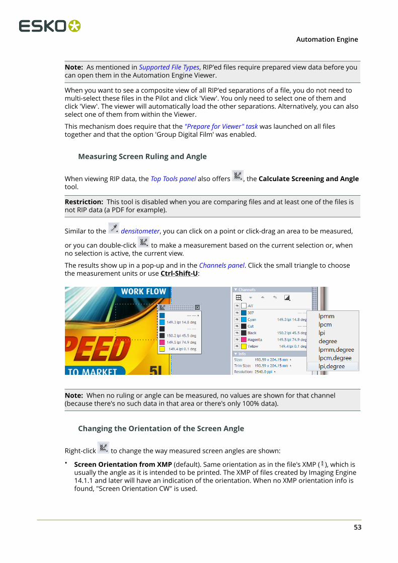
2Automation Engine
Note: As mentioned in Supported File Types, RIP'ed files require prepared view data before youcan open them in the Automation Engine Viewer.
When you want to see a composite view of all RIP'ed separations of a file, you do not need tomulti-select these files in the Pilot and click 'View'. You only need to select one of them andclick 'View'. The viewer will automatically load the other separations. Alternatively, you can alsoselect one of them from within the Viewer.
This mechanism does require that the "Prepare for Viewer" task was launched on all filestogether and that the option 'Group Digital Film' was enabled.
Measuring Screen Ruling and Angle
When viewing RIP data, the Top Tools panel also offers , the Calculate Screening and Angletool.
Restriction: This tool is disabled when you are comparing files and at least one of the files isnot RIP data (a PDF for example).
Similar to the densitometer, you can click on a point or click-drag an area to be measured,
or you can double-click to make a measurement based on the current selection or, whenno selection is active, the current view.
The results show up in a pop-up and in the Channels panel. Click the small triangle to choosethe measurement units or use Ctrl-Shift-U:
Note: When no ruling or angle can be measured, no values are shown for that channel(because there's no such data in that area or there's only 100% data).
Changing the Orientation of the Screen Angle
Right-click to change the way measured screen angles are shown:
• Screen Orientation from XMP (default). Same orientation as in the file's XMP ( ), which isusually the angle as it is intended to be printed. The XMP of files created by Imaging Engine14.1.1 and later will have an indication of the orientation. When no XMP orientation info isfound, "Screen Orientation CW" is used.
53

2 Automation Engine
• Screen Orientation (C)CW. You can also choose to see the screen angle CW (clockwise,downwards counting) or CCW (counter-clockwise, upwards counting).
Checking Registration Errors while Viewing Dots
The registration error tool is also available when viewing RIP data.
Here is an example where a white gap appears on a file that was trapped with 0.2 mm, whilesimulating a max error of 0.3 mm:
Extra Set of View Data for Print Simulation
When using advanced screening effects, it is possible that the dot on screen does not look likethe dot when printed.
Esko RIPs allow creating an extra set of view data that simulate the printed dots. This is anextra option in the tab 'Output' of an Imaging Engine task ticket.
An example. On the left we see a Concentric screen at 27% (with its typical ring-shaped holes).On the right we see its print simulation, where the holes were filled with ink:
Learn more about creating print simulation view data in the user guide of Imaging Engine, inInspecting Screens with Advanced Screening Effects.
Note: For the Automation Engine Viewer, both the RIP files and the extra print simulation files(with an extension .view) still need to be prepared for viewing.
54

2Automation Engine
2.10. Keyboard Shortcuts
Note: Many of these keyboard shortcuts are also mentioned on the page describing therelated topic.
On a Mac, as a standard practice, replace below mentioned Right-click by ctrl-click andreplace Ctrl- by cmd-.
Table: Keyboard Shortcuts
Ctrl-Down Arrow Pan 1/4 window down
Ctrl-Left Arrow Pan 1/4 window left
Ctrl-Right Arrow Pan 1/4 window right
Ctrl-Up Arrow Pan 1/4 window up
End Go to last file or page
Home Go to first file or page
Page Down Go to next file or page
Page Up Go to previous file or page
Ctrl-Shift-Spacebar Temporarily shift to pan mode (hand)
Ctrl Switches the zoom in tool to a zoom out tool
Ctrl-'+' Zoom in by a factor 2
Ctrl-'-' Zoom out by a factor 2
Ctrl-Shift-'+' Rotate view 90 degrees clockwise
Ctrl-Shift-'-' Rotate view 90 degrees counter clockwise
Ctrl-0 Show all channels
Ctrl-1 to Ctrl-9 Show channel 1 to 9
Ctrl-Shift-0 to Ctrl-Shift-9 Show channel 10 to 19
Ctrl-A Select all
Ctrl-D Clear selection
Ctrl-H Toggle overprint highlight on/off
Ctrl-L Auto align
Ctrl-M Mirror view
Ctrl-N Toggle between channels showing them one at a time
Ctrl-O Open (current) file
55

2 Automation Engine
Ctrl-R Toggle seamless view guide lines on/off
Ctrl-S Toggle between current and previous view (in difference view mode)
Ctrl-U Toggle size units
Ctrl-Shift-U Toggle resolution and screen ruling units
Ctrl-Shift-V Displays (2 seconds) the current view resolution
F1 Show online help
F2 Previous view
Shift-F2 Next view
F5 Zoom in
F6 Zoom out
F7 Temporarily shift to pan tool. Returns to previous tool after one panoperation
F8 Temporarily shift to zoom tool. Returns to previous tool after one zoomoperation
F9 Zoom to fit image in current view
Table: Mouse Shortcuts
Right button + click Zoom in by a factor 2
Right button + drag Zoom in on the selected area
Right button + Ctrl + click Zoom out by a factor 2
Double-click Screening and
Angle tool
Measure screen ruling and angle centered in currentselection
Double-click Densitometer Measure dot percentage for current selection (if any present)or current view
Double-click Zoom tool Zoom to fit selection (if any present) or full image
56
3Automation Engine
3. PitStop Preflight
3.1. Preflight Concept
Preflighting can be done for several reasons:
• Just to check a file (no "fixes" done).• To check and correct ("fix").• To do more than just fixes, to edit a file through one or many "actions".
There also several ways to make preflighting a part of your workflow:
• You can send the design back for others to correct it.• You can correct what was found to be wrong and continue the workflow.• Right before sending the file to output, you can do (another) final check, now to prevent
outputting wrong data.
ToolsAutomation Engine's PitStop Profile Editor is where you can create and manage
• PitStop Profiles: A set of rules that a file's content should adhere to.
• PitStop Action Lists: A set of changes you want to execute on a file.
In Automation Engine, you can use these profiles or action lists by using the Preflight withPitStop task.
3.2. The PitStop Profile Editor
You can create and manage PitStop PDF Profiles and Action Lists in Automation Engine'sPitStop Profile Editor.
You can find an extensive documentation on PitStop on https://www.enfocus.com/en/support/manuals/pitstop-server-manuals.
We here limit our description to topics specific to Automation Engine:
3.2.1. Setting Up the PitStop Profile Editor
This tool is one of the client tools that you can download from the Automation Engine ServerWeb Page.
1. Open this Server Web Page by entering http://<name of your server> or http://<name of your server>:9999 in the address field of your browser. You can find this toolin the section Client Apps, in the page Tools.
57

3 Automation Engine
2. Click Download to install the PitStop Profile Editor on your client computer.
• On Windows:
1. Double-click the downloaded Automation Engine PitStop ProfileEditor.exe.
2. Click Next and click Yes to confirm the installation.3. Browse to the install location, by default C:\Esko.4. Click Next and click Finish.
• On Mac:
1. Double-click the downloaded Automation Engine PitStop ProfileEditor.dmg.
2. Double-click the resulting .pkg file.3. Click Continue and click Change Install Location to specify an install location.4. Click Install and fill in your credentials to confirm.5. When "The installation was successful" appears, click Close to finish the
installation.3. Start the application from:
• (Windows)All Programs > Esko > Automation Engine PitStop Profile Editor > PitStopProfile Editor.
• (Mac)Applications > Automation Engine PitStop Profile Editor > PitStop ProfileEditor.
4. In Edit > Preferences, fill in the host name of your Automation Engine server. This isneeded to make this tool see the profiles and action lists on that server.
58

3Automation Engine
3.2.2. Smart Preflight: Using Variable Names in PitStop Profiles
Juts like when using task Tickets, you can reduce the number of profiles and action lists byusing SmartNames . In PitStop terminology, this concept is named "Smart Preflight".
Follow these steps:
1. Use the Pilot to create SmartNames. Learn more in Creating a SmartName (General).2. In the PitStop Profile Editor, select one of the PDF Profiles and click on . Choose New
and choose any of its options.3. In the open profile, enable one of the options in the category CHECK ON.
a) Choose any of the Available Checks.b)
Click on and choose Enable Variable Names('Variable Names' is PitStop'sterm for SmartNames).
4. Click on the blue SmartName icon to open a list with all global SmartNames.
5. Select a Variable (SmartName) and click OK.
You can use a SmartName in fields that require
• text• numbers
59

3 Automation Engine
• measurements with a size in "mm", "cm" , "in", "p" (picas) or "pt" (points)
Attention: Measurements needs to include the unit! For example "210 mm".When no unit is specified, it assumes points as unit.
For example, to represent A4 dimensions, the SmartName should resolve to"210 mm" and "297 mm". If the SmartName resolves to "210" and "297", thedimensions will be seen as 74 mm x 105 mm .
• a toggle that sets a check-box to on or off.
• Off = a SmartName value "0", "FALSE" or empty.• On = a SmartName value "1", "TRUE" or anything else.
3.3. Preflight with PitStop Task
Basics of the Preflight with PitStop task
The Preflight with PitStop task allows you to preflight a PDF file in Automation Engine usingtechnology from Enfocus. This KB article shows which version of PitStop is used internally in this"Preflight with PitStop" task.
Attention: When the input file is a normalized PDF, the task does not allow to runprofiles with the option "Allow Fixes" selected. It then also does not allow to runaction lists, regardless whether these actions change the file or not.
Note: This task uses the latest Enfocus PitStop Server preflight technology (its version number ismentioned in the report).
Preflight Result States
As a workflow step, this task by default offers four output pins where your input files can endup (hover your cursor over a pin to see its default name):
• Finished OK: When the preflight resulted in an OK status (no warnings or errors werefound).
• Finished with Warnings: When the preflight resulted in warnings (but no errors).
• Finished with Errors: When the preflight resulted in one or more errors.
• Error: When the task encounters an error unrelated to the preflight status.
60

3Automation Engine
Learn more about controlling task statuses here.
3.3.1. Preflight Tab
You can use this task to run one or more Action Lists and/or run a preflight Profile.
Attention: An Enfocus preflight profile can also contain action lists.
You can create action lists and profiles in the PitStop Profile Editor that comes with AutomationEngine.
• Action Lists: Use Add or Remove to define which action lists you want to run. Use MoveUp / Down to change the order in which they will be executed.
• Profile: If you want to check the PDF against a profile, select a preflight profile from the list.
Note: You can use Variable Names inside profiles or action lists. This makes the profile oraction list 'smart'. Learn more about this concept of Smart Preflight in Smart Preflight: UsingVariable Names in PitStop Profiles on page 59
Extra Task Status Options When Used as a Single Ticket
When you open a single ticket (when it is not a step in a workflow), extra options appear (as inabove screen shot):
• In When rules are violated, choose what happens when preflighting results in errors: Taskends with warning or Task fails.
• In When warnings appear, choose what happens when preflighting results in warnings:Task ends OK, Task ends with warning or Task fails.
61
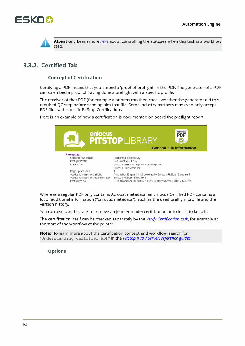
3 Automation Engine
Attention: Learn more here about controlling the statuses when this task is a workflowstep.
3.3.2. Certified Tab
Concept of Certification
Certifying a PDF means that you embed a 'proof of preflight' in the PDF. The generator of a PDFcan so embed a proof of having done a preflight with a specific profile.
The receiver of that PDF (for example a printer) can then check whether the generator did thisrequired QC step before sending him that file. Some industry partners may even only acceptPDF files with specific PitStop Certifications.
Here is an example of how a certification is documented on board the preflight report:
Whereas a regular PDF only contains Acrobat metadata, an Enfocus Certified PDF contains alot of additional information ("Enfocus metadata"), such as the used preflight profile and theversion history.
You can also use this task to remove an (earlier made) certification or to insist to keep it.
The certification itself can be checked separately by the Verify Certification task, for example atthe start of the workflow at the printer.
Note: To learn more about the certification concept and workflow, search for"Understanding Certified PDF" in the PitStop (Pro / Server) reference guides.
Options
62
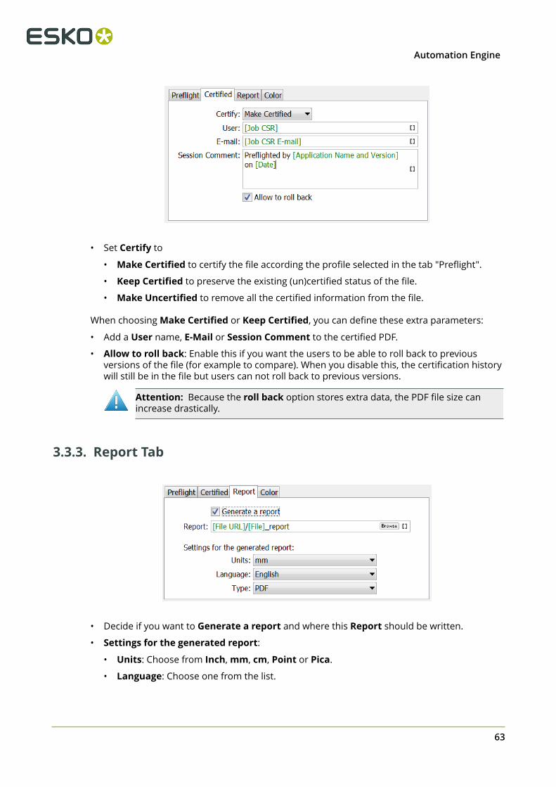
3Automation Engine
• Set Certify to
• Make Certified to certify the file according the profile selected in the tab "Preflight".
• Keep Certified to preserve the existing (un)certified status of the file.
• Make Uncertified to remove all the certified information from the file.
When choosing Make Certified or Keep Certified, you can define these extra parameters:
• Add a User name, E-Mail or Session Comment to the certified PDF.
• Allow to roll back: Enable this if you want the users to be able to roll back to previousversions of the file (for example to compare). When you disable this, the certification historywill still be in the file but users can not roll back to previous versions.
Attention: Because the roll back option stores extra data, the PDF file size canincrease drastically.
3.3.3. Report Tab
• Decide if you want to Generate a report and where this Report should be written.
• Settings for the generated report:
• Units: Choose from Inch, mm, cm, Point or Pica.
• Language: Choose one from the list.
63

3 Automation Engine
• Type: Choose if you want a PDF or XML report, or both.
Preflight Report Contents
A preflight report contains the Errors and Warnings found during the preflight, and also liststhe Fixes it may have done.
An example of the first page of a PDF report:
Tip: You can make reports appear on their own task status output pin. Learn more inConfiguring Output Statuses.
3.3.4. Color Tab
64

3Automation Engine
Preflighting often includes color conversions. Unlike normalized PDFs, native PDFs can containobjects in RGB or device independent color spaces.
When the action list or profile includes a color conversion, you can here specify the default ICCprofile that will be used for objects that were not tagged with one yet.
To do so, select Enable Color Management and choose an ICC profile for the object types inGrayscale, RGB, CMYK or Lab.
3.4. Verify Certification Task
Note: The concept of certification is described in this page about the tab 'Certify' in the 'Preflightwith PitStop' task.
Certifying a PDF stores the preflight information on board the PDF file. This includes thepreflight profile, the preflight report and the information whether the PDF has subsequentlybeen modified.
If you do not re-certify a PDF after it has been modified, it is no longer certified.
You can certify a PDF using PitStop Pro, PitStop Server or by using the 'Preflight with PitStop'task.
The Verify Certification task checks if the PDF file was certified to comply with the settings ofthe profile that you indicated in Verify against a Profile.
The task's status will be 'Verification OK' when the profile that was used to certify the PDF isidentical or stricter than the profile selected in this task.
65

4 Automation Engine
4. Global Vision Inspection Tasks
4.1. IntroductionAutomation Engine offers a set of tasks that use technology from the company Global Vision:
• Inspect Artwork compares files.• Inspect Barcodes detects and decodes barcodes in the file.• Inspect Braille detects and decodes braille in the file.• Inspect Spelling checks spelling (of a chosen language).• Inspect Text checks text rules.
Profiles
Several of these tasks ask you to select an inspection Profile. You can change and create suchprofiles using the Global Vision profile Editor.
These Tasks Require a Software License from Global Vision
To enable these Inspection tasks, you need to get a license from Global Vision and then have itinstalled on Automation Engine. You can also purchase this license via Esko, as a subscription.
Learn more in the Configure panel where you do this.
4.2. Recurring Options in Global Vision TasksThe following options are available in several Global Vision tasks:
Resolution
Several tasks first rasterize the files to RGB files and then inspect that data (PNG files). Thisoption allows you to define the resolution of these RGB images. The minimum supportedresolution is 72 ppi, the maximum is 2400 ppi.
Note: The default resolution is 300 ppi. Do not set this higher when it is not necessary.Creating high resolution raster data is a significant load for the server. See this other note withspecific information about a different resolution that is used to inspect barcodes.
Note: Low resolutions like 72 ppi may not be good enough to detect differences. Especiallybraille needs a higher resolution.
Note: These RGB images are written in a central temporary folder that is automaticallydeleted when the task ends successfully.
66
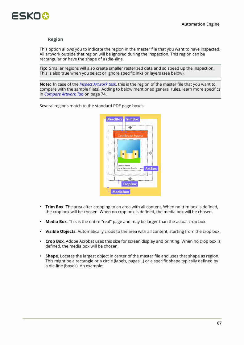
4Automation Engine
Region
This option allows you to indicate the region in the master file that you want to have inspected.All artwork outside that region will be ignored during the inspection. This region can berectangular or have the shape of a (die-)line.
Tip: Smaller regions will also create smaller rasterized data and so speed up the inspection.This is also true when you select or ignore specific inks or layers (see below).
Note: In case of the Inspect Artwork task, this is the region of the master file that you want tocompare with the sample file(s). Adding to below mentioned general rules, learn more specificsin Compare Artwork Tab on page 74.
Several regions match to the standard PDF page boxes:
• Trim Box. The area after cropping to an area with all content. When no trim box is defined,the crop box will be chosen. When no crop box is defined, the media box will be chosen.
• Media Box. This is the entire "real" page and may be larger than the actual crop box.
• Visible Objects. Automatically crops to the area with all content, starting from the crop box.
• Crop Box. Adobe Acrobat uses this size for screen display and printing. When no crop box isdefined, the media box will be chosen.
• Shape. Locates the largest object in center of the master file and uses that shape as region.This might be a rectangle or a circle (labels, pages...) or a specific shape typically defined bya die-line (boxes). An example:
67

4 Automation Engine
Alternatively, you can define the shape in the Options... dialog:
• Define shape by Inks. Use this when you want to specify the shape by using thebounding box of all data in the here defined ink. You here typically define the ink of thedie line. All objects inside the shape (contour) that can be formed out of the data in thatink will be inspected. Process inks are not supported to define a shape.
Click on to get a list of the inks of the input file. Use Ctrl/cmd- or Shift-select to selectmultiple inks.
Note: In case of the Inspect Artwork task, although you here selected them from theinput file, the ink(s) will serve to find a region in the master file.
Note: The input field is not case sensitive.
Attention: When specifying multiple inks (for example "die,cut,knife"),
• only the first one of which a shape can be made will be used.• when none of them can be used as a shape, the task will result in an error.
• Define shape by Layers. Similar to above Inks. All objects inside the shape (contour) thatcan be formed out of the data in that layer will be inspected.
Ignoring Ink or Layers
Ignoring an ink or layer means that their data will not be part of the raster image and so notpart of the inspection.
• Ignore Inks. Click on to have them read from the task input file (you can multi-selectin this dialog). Use this for example if you have made a difference in the ink used for text.In such case, you could here choose to ignore that ink to check if there are any unwanteddifferences in the other inks.
• Ignore Layers. Same as above "Ignore Inks", but to ignore layers. You can for exampleignore the layer that contains the images.
Attention: It is also common to here ignore the ink or layer that was used to definea region based on a shape. For example: inspect the region defined by the shape ofthe ink "die line" and also here also add the ink "die line"'to ignore it from thecomparison.
68
4Automation Engine
Report
All "Inspect" tasks write report(s).
• Report File. Define the report's location and name. When you use SmartNames to definea relative path, the report will be created relative to the parent folder of the input file. Thetask will fail when the report tries to overwrite the input file.
Tip: You can configure an extra output pin to see the report appear on its own pin. Learnmore in Configuring Output Statuses.
• Report Type. Choose whether you want a PDF and/or an XML report.
• A PDF report contains several pages, showing and describing what it found during theinspection. The first page shows the bounding box of the region that was inspected.
The first page of the report shows a preview of the RGB data. It also shows bounding boxaround the region that was inspected (in pink). When any inks or layers were ignored,this data will also not be shown here.
• An XML report contains the file URLs and details of what was found during theinspection.
• Add annotations output pin. This will add an extra workflow step output pin so it becomespossible to launch specific tasks on the XFDF annotation file (if the type of task writes it).learn more about working with these annotation files in Inspection Results as Annotations inViewers on page 69.
4.3. Inspection Results as Annotations in Viewers
The five "Inspection" tasks generate XFDF files that contain inspection annotations. These XFDFfiles are written in a hidden subfolder.
These annotations show up in the Automation Engine Viewer. Learn more in Working withAnnotations on page 49.
These annotations can also show up in the WebCenter Viewer. Learn more in the below pageabout Seeing Inspection Annotations in the WebCenter Viewer on page 69.
4.3.1. Seeing Inspection Annotations in the WebCenter Viewer
There are 2 ways to see the annotations in the WebCenter Viewer:
• When publishing an inspected file from Automation Engine to WebCenter.• When launching the inspection from WebCenter itself.
Publishing an Inspected File to WebCenter
When you ran an inspection task in Automation Engine and you then use the Publish onWebCenter task, you can select its option Publish Annotations to make sure that also the XFDFfile is published to the chosen WebCenter project.
When you then view the document in the WebCenter Viewer, the annotations will also bevisible.
69

4 Automation Engine
Launching the Inspection from WebCenter
In this case, WebCenter triggers the inspection(s) (and creation of the XFDF). It does this as partof a WebCenter Task that triggers a workflow on its own OBGE (or on an external AutomationEngine).
We illustrate this workflow by means of an example:
Attention: This example assumes you are familiar with creating WebCenter Tasks.Learn more in the WebCenter documentation.
Here are the main steps to set up this workflow:
1. In your WebCenter project (template), define a WebCenter Task that contains a SubmitWorkflow that will launch the inspection task(s) on a graphics file.
2. The Submit Workflow step in that WebCenter Task links to a workflow that uses inspectiontasks where you configured an extra output pin in for the annotation file. This XFDF file is soforwarded to the Integrate with WebCenter task (more details on this task in below steps).For example:
3. The Submit Workflow step in that WebCenter Task needs to use the Workflow
Parameters "Add Document properties" See an example:
70
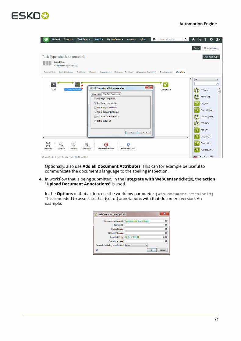
4Automation Engine
Optionally, also use Add all Document Attributes. This can for example be useful tocommunicate the document's language to the spelling inspection.
4. In workflow that is being submitted, in the Integrate with WebCenter ticket(s), the action"Upload Document Annotations" is used.
In the Options of that action, use the workflow parameter [wfp.document.versionid].This is needed to associate that (set of) annotations with that document version. Anexample:
71

4 Automation Engine
4.4. Inspect Artwork
Note: This is one of several inspection tasks that use technology from the company GlobalVision. Learn about the general concept and setup in the Introduction on page 66.
4.4.1. Concept and Workflow
Concept
This task compares one or more 'sample' files to a 'master' file. It selects the defined region ofinterest, aligns the files and then compares them. It supports multi-page inspections as well asstep & repeat files.
Comparing files is typically done
• to make sure files are identical when you ignore a specific ink or layer.• to make sure only the intended differences are there.
The tasks detects these types of differences:
• Text changes (moved, missing, broken, added)• Font changes (size, style)• Graphics (deletion, insertion, change)• Color• Registration
Technique
The task prepares RGB raster data of the sample and master file at a custom resolution andthen compares that raster data.
This task compares colors, meaning the way as if a human eye or a camera or a scanner looksat the files. For example if the task sees that a green object is the exact same color in bothmaster and sample file, it will not see this as a difference, no matter what separations thatgreen color is made up of.
Note: In the Automation Engine Viewer, the default compare mode is one that comparesseparations ('channels'). In that mode, the Viewer will detect a difference if the same greenobject is in one file made up of a Pantone ink and in the other file a mix of CMYK. The Vieweralso offers the mode to compare HSV values, which is similar to the mode this task uses.
Note: This task is similar to the Compare PDF task.
The found differences are mentioned in the report file but are also written as an XFDF file (astandard Acrobat comments file). When you open the inspected sample file in the AutomationEngine Viewer, the viewer will read this XFDF file and show its contents in the annotations list.Learn more in Working with Annotations on page 49.
72

4Automation Engine
Smart comparing
The task automatically uses these features:
• Rotation detection. The task detects if the sample file is a rotated version of the master fileand takes this into account when inspecting.
• Skew correction and alignment. This is for example useful when one of the files is a scanthat was slightly angled when being scanned.
• Repeat detection. The task automatically detects if a file is a repeated area inside the otherfile. Such detected repeats are mentioned and shown in the report file.
Supported File Types
The sample and the master files can be any of these file types:
• PDF• Normalized PDF• PDFPLA• AI Adobe Illustrator (when PDF compatible)• TIFF (1-bit and 8-bit. Multichannel images are not supported)• LEN• JPEG• PNG• BMP• Folder
Detailed Reporting
A detailed PDF report lists and visualises the found differences. An XML report details thecoordinates of where differences were found. Learn more in Report Tab on page 75.
Status and Workflow Output Pins
The sample file (task input file) is also the task output file. This makes it easy to continue yourworkflow with this file. It will be placed on one of these output pins:
• Match. When no differences were found.
• Mismatch. When one or multiple differences were found.
• Error. When the task itself could not function properly. For example when no profile wasselected, when the master file could not be found or when the files could not be matched.
See an example (to help visualize the output pins, an end status step was created with thesame name as the status):
73

4 Automation Engine
Tip: To get that extra output pin for the report(s) as in above example, you will need toconfigure it as mentioned in the page about the inspection report.
Integration with Automation Engine Viewer
When opening the sample file in the Automation Engine Viewer, the area where differenceswere found are shown in red rectangles and automatically become part of the Annotationslist. Learn more in Working with Annotations on page 49.
4.4.2. Compare Artwork Tab
• Compare With. Indicate the master file you that want to compare your input sample file(s)with.
Note: This field needs a full URL (path). When using SmartNames, make sure you alsodefine a file extension.
When the task input is a folder, you here also need to define a folder. The first file in themaster folder is compared with the first one in the sample folder. The second master one tothe second sample one, etc. When the amount of files in the input folder is not equal to thatin the master folder, the task ends in error. The task does not check files in subfolders.
• Compare Resolution. This option is present in several Global Vision tasks. Learn more inGeneric Option "Resolution".
• Profile. An inspection profile is a collection of parameters that define how (precise) toinspect. Profiles differ (slightly) in thresholds of what you consider as differences. They arecentrally located *.ini files that you can adapt using the "Global Vision Profile Editor". You canthere both adapt the default inspection profiles or create your own.
Attention: The profiles listed below are the default ones from Global Vision. Youmight use a (test-)version that already offers other profiles that were fine-tuned forEsko prepress workflows.
• None. The task will end in error when you do not select a profile.
• Booklet. Choose this setup to compare multi-page files. It will compare all pages of thesample file with each same-number page of the master-file. Alternatively, for a slightlymore precise inspection, choose Digital and select Multipage.
74

4Automation Engine
• Digital to Scan. Choose this profile to compare a digital artwork file to a scanned masterfile.
• Digital. Choose this profile to compare revisions or variations of digital artwork.
• Proof. Choose this profile to compare files that are supposed to be the same. This istypically to compare digital artwork against a digital proof. Also use it to compare aproof against a printed hard copy. This profile uses refine, auto distort and smoothing tocompensate for changes in the image.
• Scan to Scan. Choose this profile to compare scanned files.
Note: The parameters of the chosen profile are listed on the last page of the report.
• Multipage. By default only the first page of a document is inspected. Select this option tocompare all pages of the input multi-page sample file to each same-number page of themaster file.
Note: The task will end in error when the sample file and the master file do not have thesame number of pages.
Note: This option is ignored when the profile 'Booklet' is chosen (or any other customprofile that already uses the multipage parameter in its configuration).
• Region. This option is present in all Global Vision tasks. Learn its basics in Generic Option"Region". As this task has both a master and sample file(s), these following notes areimportant:
Note: When using a region based on a Shape, the task looks for the content of the definedshape in the master file and looks for that similar content in the sample file. This also donewhen choosing regions based on Trim or Media Box: the content in that box of the masterfile will be looked for in the sample file and then compared.
Caution: Even when you select an ink or layer from the list of those in the inputsample file, this ink or layer is used to find a shape in the master file.
• Ignore Inks and Ignore Layers. These options are present in several Global Vision tasks.Learn more in Generic Options "Ignore Inks or Layers".
• Configure. This button opens the item in the configure panel where you can activate thesoftware license that you acquired from Global Vision.
4.4.3. Report Tab
This option is present in several Global Vision tasks. Learn more in the Generic Option "Report".We here only mention some specifics for this task.
Caution: The last page of the PDF report summarizes the parameters of the profilechosen in the task ticket. Any parameters that were chosen separately in the Esko ticket(like resolution), and that overruled parameters in that profile, are not mentioned here.This means that the here mentioned 'Desired DPI' is possibly not the one that wasreally used for inspection.
75

4 Automation Engine
4.5. Inspect Barcodes
Note: This is one of several inspection tasks that use technology from the company GlobalVision. Learn about the general concept and setup in the Introduction on page 66.
4.5.1. Concept and Workflow
This task inspects all barcodes in a file. It scans and decodes them and verifies their grade(quality level) against the minimum grade chosen in the ticket.
A barcode quality problem could for example be that it is too small or it could have too littlecolor contrast, a QR code could miss some parts, etc.
You can also check if the barcodes defined in the Product or Job database are present in thefile.
The main advantage of this task is that you do not have to open these files and check themvisually or use a device to verify them. The detailed report is also a useful step in your qualitycontrol process.
Note: You can use the Global Vision Profile Editor to compare barcodes in a master and samplefile.
This task also checks the barcode "quiet zones". For 2D barcodes, a specific grade is given forthese zones, one for each side, 100% when the zone is big enough.
Supported Barcodes
Attention: Add-on codes and composite codes are not supported. UPC-A or EAN-13add-on codes are recognized but are not graded.
• 1D/Linear codes:
• PharmaCode• RSS/GS1 Databar Omnidirectional Stacked• RSS/GS1 Databar Expanded• RSS/GS1 Databar Limited• RSS/GS1 Databar Stacked• RSS/GS1 Databar Expanded Stacked• RSS/GS1 Databar Omnidirectional• RSS/GS1 Databar Truncated• UPC-E• UPC-A• EAN 13• EAN 8• Code 39• Code 93• Code 128
76
4Automation Engine
• GS1 128• MSI• Interleaved 2 of 5• Codabar• ITF-14• ITF-16• Telepen (only decoding supported)• Code 11 (only decoding supported)• UPC-A add-on codes (only decoding supported)
• 2D codes:
• Data Matrix• GS1 Data Matrix• QR• MicroQR
Detecting Rotated Barcodes
For linear barcodes, the option "Support Rotation" in the profile needs to be enabled inorder to be guaranteed that a rotated barcode is detected. If the option is not enabled, linearbarcodes can only be detected when in 0, 90, 180 and 270 degree angles.
However, because linear barcodes can be sheared, it is possible that rotated barcodes are stilldetected even if the option "Support Rotation" is not enabled.
Rotated 2d barcodes with an angle other that 0, 90, 180, 270 degrees can not be guaranteed tobe detected.
Supported File Types
The input file types supported by this task are the same as described here for the Inspect Artworktask, here excluding the type 'Folder'.
Status and Workflow Output Pins
The task input file is also the task output file. It will be placed on one of these output pins:
• OK. When all barcodes are conform to the chosen minimum barcode grade and, when thatoption is selected, all the barcodes described as product or job barcode are found (withtheir specified parameters). Learn about these options in this next page.
• Not OK (status 'Warning'). When one or more barcodes are not conform the chosenminimum grade, or, when that option is selected, when a barcode described as product orjob barcode is not found or has different parameters. This is also the status when the inputfile has no barcodes.
• Warning. When all barcodes are conform the chosen minimum grade, and, when thatoption is selected, when a barcode described as product or job barcode is not found or hasdifferent parameters.
• Error. When the task itself could not function properly. For example when no profile wasselected, or no license was available.
See an example (to help visualize the output pins, an end status step was created with thesame name as the status):
77
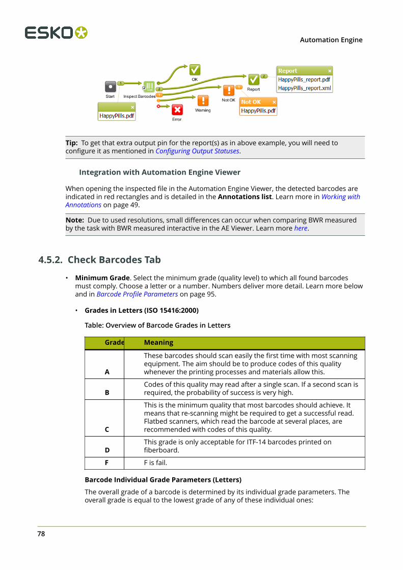
4 Automation Engine
Tip: To get that extra output pin for the report(s) as in above example, you will need toconfigure it as mentioned in Configuring Output Statuses.
Integration with Automation Engine Viewer
When opening the inspected file in the Automation Engine Viewer, the detected barcodes areindicated in red rectangles and is detailed in the Annotations list. Learn more in Working withAnnotations on page 49.
Note: Due to used resolutions, small differences can occur when comparing BWR measuredby the task with BWR measured interactive in the AE Viewer. Learn more here.
4.5.2. Check Barcodes Tab
• Minimum Grade. Select the minimum grade (quality level) to which all found barcodesmust comply. Choose a letter or a number. Numbers deliver more detail. Learn more belowand in Barcode Profile Parameters on page 95.
• Grades in Letters (ISO 15416:2000)
Table: Overview of Barcode Grades in Letters
Grade Meaning
A
These barcodes should scan easily the first time with most scanningequipment. The aim should be to produce codes of this qualitywhenever the printing processes and materials allow this.
BCodes of this quality may read after a single scan. If a second scan isrequired, the probability of success is very high.
C
This is the minimum quality that most barcodes should achieve. Itmeans that re-scanning might be required to get a successful read.Flatbed scanners, which read the barcode at several places, arerecommended with codes of this quality.
DThis grade is only acceptable for ITF-14 barcodes printed onfiberboard.
F F is fail.
Barcode Individual Grade Parameters (Letters)
The overall grade of a barcode is determined by its individual grade parameters. Theoverall grade is equal to the lowest grade of any of these individual ones:
78

4Automation Engine
Table: Value of Individual Grade Factors in overall Barcode grade (Letters)
BarcodeGroupType
IndividualGradeParameter Meaning
1D/Linear
MinimumReflectance
Pass or fail grade (A or F) and the minreflectance value (darkest part of thebarcode).
1D/Linear
SymbolContrast
The difference in contrast between thedarkest and the lightest part of a barcode(%).
1D/Linear
MinimumEdgeContrast
Pass or fail grade (A or F) determined by theminimum contrast between a space and itsadjacent bars.
1D/Linear Modulation
The ratio between symbol contrast andminimum edge contrast.
1D/Linear Defects
The amount of discrepancies in thereflectance of a barcode.
1D/Linear Decode
Pass or fail grade (A or F) determined bywhether the barcode was generated correctly(i.e. sufficient spacing between bars).
1D/Linear Decodability The ease of barcode identification.
2D ModulationThe contrast difference between light anddark regions.
2D Decode
Pass or fail grade (A or F) determined bywhether the barcode was generated correctly(for example sufficient spacing betweenbars).
2DAxial Non-Uniformity
The difference in length of the two axis of thebarcode.
2DGrid Non-Uniformity
The vector deviation of the barcode from anideal position.
2D
FixedPatternDamage
The damage done to the pattern of abarcode.
2D
UnusedErrorCorrection
The amount of unused error correctionembedded in the barcode.
• Grades in Numbers (ISO 15416:2016)
This new calculation method can in some cases result in a higher averaged score for theabove parameters using this interpolation method compared with the method usingletters (ISO 15416:2000).
79

4 Automation Engine
Find more details about the decimal grades method in http://www.aisvision.com/files/2815/1602/9515/ISO_15416_December_2016_Changes.pdf and in https://www.sis.se/api/document/preview/921309/.
There are 41 possible grades: 0.0 , 0.1, 0.2 up to 4.0 (source http://www.axicon.com/fractional-grading.html).
Table: Value of Individual Grade Factors in overall Barcode grade (Numbers)
GradeSymbolcontrast ModulationDecodabilityDefects Decode
Rmax/Rmin
Min.EdgeContrast
0.0<15%
<30%
<20%
>30% Fail < 2 < 15%
0.1to0.9
15%to19%
30%to39%
20%to24% NA
1.0to1.9
20%to38%
40%to49%
25%to36%
26%to30%
2.0to2.9
39%to54%
50%to59%
37%to49%
21%to29%
3.0to3.9
55%to69%
60%to69%
50%to61%
16%to20%
4.0>=70%
>=70%
>=62%
<=15% Pass >= 2
>=15%
• Profile. An inspection profile is a collection of parameters that defines how (precise) toinspect. They are centrally located *.ini files that you can adapt using the Esko tool "GlobalVision Profile Editor". You can there both adapt the default inspection profiles or create yourown.
When unsure, use the Default profile. Selecting None will result the task to end in error.
• Compare barcode data with job or product barcode data. When this option is selected,the task will, after having checked the minimum grade, also check if all barcodes specifiedin the Product Part Properties or in the Job Setup of the input file are present as such in thisfile. Not just their type or code, but also all the other parameters entered in those productor job parameters.
This table shows you how the terms in Automation Engine's product and job parametersmap to the terms used by Global Vision (that are also used in the reports).
Automation Engine term Global Vision term
BOBST Laetus Pharma Code
CLF-8 Laetus Pharma Code
CODABAR Codabar
CODE-128 Code 128
80
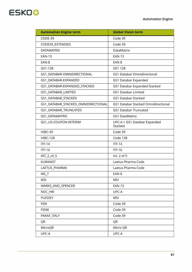
4Automation Engine
Automation Engine term Global Vision term
CODE-39 Code 39
CODE39_EXTENDED Code 39
DATAMATRIX DataMatrix
EAN-13 EAN 13
EAN-8 EAN 8
GS1-128 GS1 128
GS1_DATABAR-OMNIDIRECTIONAL GS1 Databar Omnidirectional
GS1_DATABAR-EXPANDED GS1 Databar Expanded
GS1_DATABAR-EXPANDED_STACKED GS1 Databar Expanded Stacked
GS1_DATABAR_LIMITED GS1 Databar Limited
GS1_DATABAR_STACKED GS1 Databar Stacked
GS1_DATABAR_STACKED_OMNIDIRECTIONAL GS1 Databar Stacked Omnidirectional
GS1_DATABAR_TRUNCATED GS1 Databar Truncated
GS1_DATAMATRIX GS1 DataMatrix
GS1_US-COUPON-INTERIM UPC-A + GS1 Databar ExpandedStacked
HIBC-39 Code 39
HIBC-128 Code 128
ITF-14 ITF-14
ITF-16 ITF-16
INT_2_of_5 Int. 2 of 5
KURANDT Laetus Pharma Code
LAETUS_PHARMA Laetus Pharma Code
MS_7 EAN 8
MSI MSI
MARKS_AND_SPENCER EAN 13
NDC_HRI UPC-A
PLESSEY MSI
PZN Code 39
PZN8 Code 39
PARAF_ITALY Code 39
QR QR
MicroQR Micro QR
UPC-A UPC-A
81
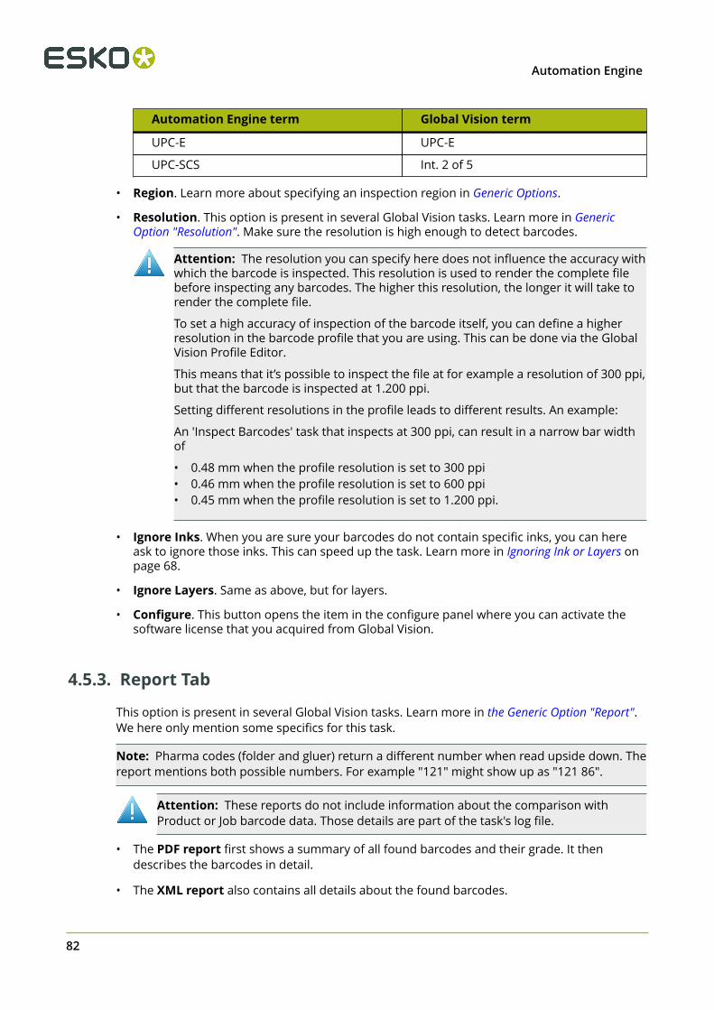
4 Automation Engine
Automation Engine term Global Vision term
UPC-E UPC-E
UPC-SCS Int. 2 of 5
• Region. Learn more about specifying an inspection region in Generic Options.
• Resolution. This option is present in several Global Vision tasks. Learn more in GenericOption "Resolution". Make sure the resolution is high enough to detect barcodes.
Attention: The resolution you can specify here does not influence the accuracy withwhich the barcode is inspected. This resolution is used to render the complete filebefore inspecting any barcodes. The higher this resolution, the longer it will take torender the complete file.
To set a high accuracy of inspection of the barcode itself, you can define a higherresolution in the barcode profile that you are using. This can be done via the GlobalVision Profile Editor.
This means that it’s possible to inspect the file at for example a resolution of 300 ppi,but that the barcode is inspected at 1.200 ppi.
Setting different resolutions in the profile leads to different results. An example:
An 'Inspect Barcodes' task that inspects at 300 ppi, can result in a narrow bar widthof
• 0.48 mm when the profile resolution is set to 300 ppi• 0.46 mm when the profile resolution is set to 600 ppi• 0.45 mm when the profile resolution is set to 1.200 ppi.
• Ignore Inks. When you are sure your barcodes do not contain specific inks, you can hereask to ignore those inks. This can speed up the task. Learn more in Ignoring Ink or Layers onpage 68.
• Ignore Layers. Same as above, but for layers.
• Configure. This button opens the item in the configure panel where you can activate thesoftware license that you acquired from Global Vision.
4.5.3. Report Tab
This option is present in several Global Vision tasks. Learn more in the Generic Option "Report".We here only mention some specifics for this task.
Note: Pharma codes (folder and gluer) return a different number when read upside down. Thereport mentions both possible numbers. For example "121" might show up as "121 86".
Attention: These reports do not include information about the comparison withProduct or Job barcode data. Those details are part of the task's log file.
• The PDF report first shows a summary of all found barcodes and their grade. It thendescribes the barcodes in detail.
• The XML report also contains all details about the found barcodes.
82

4Automation Engine
4.6. Inspect Braille
Note: This is one of several inspection tasks that use technology from the company GlobalVision. Learn about the general concept and setup in the Introduction on page 66.
4.6.1. Concept and Workflow
This task detects braille, translates it to a chosen language and displays information such asthe language, number of dots, number of characters, number of lines, dot spacing, characterspacing, word spacing and line spacing values.
Braille should comply to the Marburg Medium braille specification. Braille that does not complymight get misinterpreted. For example wrongly grouping dots of different characters into onecharacter, or not detecting certain dots to be part of the braille, or not recognizing the braille atall.
The task can also compare the found braille to a given text.
Note: You can use the Global Vision Profile Editor to compare braille data between a masterand sample file.
Supported File Types
The input file types supported by this task are the same as described here for the Inspect Artworktask, except the type 'Folder'.
Status and Workflow Output Pins
When finished, the task input file will be placed on one of these output pins:
• OK. When no error occurred and when the compare option is not enabled.
• Not OK (status "warning"). When the option compare was used and found a mismatch.
Attention: A mismatch will not be shown in the report file (the actual comparison isdone with the report data). Mismatches are mentioned at the bottom of the task logfile. For example:
INFO: GlobalVisionTask.INFO.ComparingWithBrailleDataERROR: GlobalVisionTask.Message.BrailleDataDifference (< correct text >, < mismatch >)
• Error. When the task itself could not function properly. For example when no license wasavailable.
Tip: To get an extra output pin for the report(s), you will need to configure it as mentioned inthe page about the inspection report.
83

4 Automation Engine
Integration with Automation Engine Viewer
When opening the inspected file in the Automation Engine Viewer, the detected braille isindicated in red rectangles and is detailed in the Annotations list. Learn more in Working withAnnotations on page 49.
4.6.2. Check Braille Tab
• Language. Braille is written in a specific language. Some braille characters mean differentthings in different languages. Select the language in which you think that the braille code iswritten. You then will get the correctly translated version in that language.
Note: A language translation set is an XML file that describes mapping of characters. Some(pharma) companies create their own mapping style. You can use the Global Vision ProfileEditor to export and add custom languages.
• Compare. Enable this option to compare the text resulting from all the detected andtranslated braille with the text written in this field or resolved by a SmartName in this field.To indicate a new line in the text, add a space in the text field.
Attention: The comparison is done with the text in this field, not with text presentinside an external file.
Note: If your file has separate groups of braille that you want to compare with a text youdefined here in this field, you can work with layers. Add the different groups of braille todifferent layers in your file and use the option Select Layers to control which translatedbraille you here compare with the here defined (smart) text.
• Region. Learn more about specifying an inspection region in Generic Option 'Region".• Resolution. Make sure the resolution is high enough to detect braille. 72 ppi for example
will not be sufficient to detect the braille objects. Learn more in Generic Option "Resolution".• Select Inks. Braille is usually present in a specific ink or layer. Specify one or more inks
that contain the braille data. Once braille is found in one ink, all braille is expected to bein that ink (all braille in another selected ink will then be ignored). The list of inks does notdetermine the order in which the inks are searched.
• Select Layers. Same as Select Inks, but for layers. Except that when you specify multiplelayers, that not just the first (found) layer will be checked.
• Configure. This button opens the item in the configure panel where you can activate thesoftware license that you acquired from Global Vision.
4.6.3. Report Tab
This option is present in several Global Vision tasks. Learn more in the Generic Option "Report".
4.7. Inspect Spelling
Note: This is one of several inspection tasks that use technology from the company GlobalVision. Learn about the general concept and setup in the Introduction on page 66.
84

4Automation Engine
4.7.1. Concept and Workflow
Concept
This task checks the spelling of the text in the input file. You need to specify the language thetext is written in. This can also be a custom dictionary.
Attention: This task only checks spelling of live text objects (not of contourized text).
Supported File Types
This task supports PDF, Normalized PDF, PDFPLA, AI (when PDF compatible), TXT, DOC(X), RTF,XML, HTML and XLS(X) files.
Status and Workflow Output Pins
When finished, the task input file will be placed on one of these output pins:
• Match (status "OK"). When the spelling was correct.
• Mismatch (status "Warning"). When the spelling was not correct.
• Error. When no live text was found or when the task itself could not function properly (forexample when no license was available).
Tip: To get an extra output pin for the report(s), you need to configure it as mentioned in thepage about the inspection report.
Integration with Automation Engine Viewer
When opening the inspected file in the Automation Engine Viewer, the spelling violations areindicated in the Annotations list. Learn more in Working with Annotations on page 49.
4.7.2. Check Spelling Tab
• Language. Select the language the text is written in.
Note: You can customize a language (dictionary) by using the Global Vision Profile Editor.
• Region. Learn more about specifying an inspection region in Generic Option "Region".
Tip: When your file contains live text in more than one language, you could organize thedifferent texts in specific layers and then specify a layer selection in this task.
85

4 Automation Engine
• Select Layers. You can specify one or more layers that contain the text in the selectedlanguage.
4.7.3. Report Tab
This option is present in several Global Vision tasks. Learn more in the Generic Option "Report".
4.8. Inspect Text
Note: This is one of several inspection tasks that use technology from the company GlobalVision. Learn about the general concept and setup in the Introduction on page 66.
4.8.1. Concept and Workflow
Concept
This task compares the text in the input file with the text in another file. You select a profilethat defines how should be compared and what should be seen as a difference (for example ifyou consider a font type or font size change a difference).
Attention: This task only detects and compares live text objects (not contourized text).
Supported File Types
This task supports PDF, Normalized PDF, PDFPLA, AI (when PDF compatible), TXT, DOC(X), RTF,XML, HTML and XLS(X) files.
Note: For XLS(X) files only the visible text is checked, so not the text outside the visible part ofthe cell.
Status and Workflow Output Pins
When finished, the task input file will be placed on one of these output pins:
• Match (status "OK"). When the text matches.
• Mismatch (status "Warning"). When the text does not match.
• Error. When one of the files has no live text or when the task itself could not functionproperly (for example when no license was available).
Tip: To get an extra output pin for the report(s), you need to configure it as mentioned in thepage about the inspection report.
Integration with Automation Engine Viewer
86
4Automation Engine
When opening the inspected file in the Automation Engine Viewer, the found differences areindicated in the Annotations list. Learn more in Working with Annotations on page 49.
4.8.2. Compare Text Tab
• Compare with. Indicate the file (full URL) that contains the text that you want to comparewith the text from the input file. For example: your input file is a PDF and you compare itwith a Word file containing the original text.
• Profile. Select a profile that defines what should be seen as a difference and otherparameters. Learn more about these profiles in the Global Vision Profile Editor.
• Region. Learn more about specifying an inspection region in Generic Option 'Region".• Select Layers. You can specify one or more layers that contain the text.
4.8.3. Report Tab
This option is present in several Global Vision tasks. Learn more in the Generic Option "Report".
4.9. Global Vision Profile Editor
4.9.1. Concept and Workflow
The Global Vision Profile Editor is a version of Global Vision’s standalone application ArtProof/ScanProof. This Esko version has a different interface and functionality.
The main reason for an Esko user to use the Global Vision Profile Editor is to be able to testand manage the Profiles that are used in Automation Engine's Inspection tasks.
You can also use its interactive tools to compare artwork, inspect barcodes, translate braille,inspect text or spelling.
Caution: This application is very memory intensive, especially when you open filesthat are large in dimensions, or if you request a high resolution. Check if your localcomputer has enough memory on http://www.esko.com/systemrequirements (sectionAutomation Engine - Client).
License from Global Vision
As with the Inspection tasks, you need a license from Global Vision to use this application. Thiswas introduced here.
How to Install
This application is one of the tools that you can download from the Automation Engine Serverweb page.
87
4 Automation Engine
• Open this Server web page by entering http://<name of your master server> or http://<name of your master server>:9999 in the address field of your browser.
• Download this application from Client Apps > Tools.
• When asked for the Host Name, enter the name of your Automation Engine server whereyou have installed your license from Global Vision.
General Working
This application first creates rasterized files at a chosen resolution and then inspects thesefiles.
PDF files or AI files are first opened in a Prepare PDF window. You can there for example chooseto ignore inks or layers before the file is being rasterized.
File Support
• PDF and AI files (when PDF compatible)• RIP data: TIFF, LEN• Pictures: BMP, PNG, JPG
The Inspect Text and Inspect Spelling modes also support these file types:
• DOC, XLS, XLSX, XML, HTML
4.9.2. Interface Overview
1. File Menu. To load files or change the resolution that artwork files will be rasterizedwith.
Tip: You can also load files via double-clicking inside the master or sample panel. Also dothis if you loaded a wrong file and want to replace it with another.
2. Reset Interface. To clear the inspection window and all the loaded files. Do this before
starting to inspect a completely different set of files.3. Back. To close the inspection window.4.
Editor Modes. To choose to compare , inspect barcodes or translate braille .5. Action. To choose the type of action for that mode.6. Profile. To choose the specific profile for that mode and action.
Note: Choose Manage at the bottom of the list when you want to add, copy, rename ordelete a profile without activating any inspection mode. Be aware that 'Apply' also saves themade changes!
7. or or to start the inspection.8. Cancel Inspection. To stop the inspection while running.
88

4Automation Engine
9. Configure Inspection Parameters. When in inspection mode, use this one to view or
make changes to the selected profile and re-execute the changed profile.
Note: If you want save the changes to the profile, then select 'Manage' from the Profile'sdrop-down list.
Note: This icon is disabled when the chosen profile is one that was installed with theapplication (those are read-only). Use 'Manage' from the Profile's drop-down list to make acustom copy of such a profile. You can then view and make changes to that new profile.
10. Help. To change various preferences. The Hi-Contrast option is explained in Comparing
files on page 90.
4.9.3. Prepare PDF Window
When loading PDF or AI files, they are first opened in a Prepare (Master/Sample) PDFwindow. This is where you can still rotate or crop the file or hide selected separations or layersbefore the file is rasterized. These changes do not modify the original PDF/AI file.
Tool bar
• , Marquee Zoom (drag an area), Central Zoom In/Out and TotalView. These functions only affect the view in this dialog ; they do not decide what will berasterized.
• Reload file. Choose this to discard any changes made so far and re-opens the file in this"Prepare PDF" window.
• Accept. Click accept to confirm any changes you made, start the rasterization process.When done, the PDF Prepare window closes and the resulting raster data is shown in the(master or sample) "Inspection" window.
• Close. Choose this to cancel this preparation and close this window.
Left Panels• Enable overprint. In prepress environments, leave this enabled.
• You can choose to limit the region to the file's Media, Trim or Crop Box.
• Layers and Separations:
Click the eye icon to hide them in this view and exclude them from the raster data. Clickagain to show / include them again.
Right-click the name of a layer or separation to enable or disable "Use Shape as Region".Select this when you want this (die) layer or separation to be used as shape to be inspected.When no shape can be extracted from the chosen layer or separation, the crop box will bechosen.
Note: Only one layer or separation can serve as region shape at a time.
89
4 Automation Engine
• Process. The process inks cannot be used to extract a region based on a shape. You canonly double click them to hide/show them in this view and exclude/include them from theraster data.
4.9.4. Comparing files
Note: This is a quick start guide. We also assume you have read the introduction pages of theInspection tasks and of the Profile Editor.
1.Select the Compare mode .
2. Choose the Action 'Compare'.3. Choose the Profile you want to inspect with. Learn more in Compare Profile Parameters on
page 92.4. In , choose the resolution at which you want to inspect.5. In , load a master and sample file.
Note: When a file is loaded, click next to the name of the master or sample file to getinformation about the raster data or to change the appearance of the file in this window.
When loading PDF (compatible) files, the Prepare PDF window will open. Learn more aboutthis extra step in Prepare PDF Window on page 89.
6. Once a file is loaded, you can use the Inspection toolbar to make some changes before youstart the inspection. For PDF files, you could already have done some of those changes inthe Prepare PDF window.
• Define which region you want to have inspected. Select an option and a blue
dashed line will indicate the resulting region.
• Crop Box. This is typically the whole file. Learn more about PDF boxes in recurringoptions.
• Marquee. Select it and then drag an area. Optionally, when you want to target a
block of text in a single ink, click on Crop Contents to crop to the content in thatmarquee.
• Visible Objects.
• Shape. Select this option then click in the center of the shape you want. When noshape can be found, the largest object in the middle will be used as shape.
Note: The last used type of region stays selected for the next loaded master file.
• To Reload the file. In case of a PDF file, the Prepare PDF window will open again.
• To Rotate or Mirror the file.
90

4Automation Engine
Note: The application already detects rotations between master and sampleautomatically.
• Marquee Zoom and Total View. The chosen view does not affect the region toinspect.
7. Click to start the inspection. The region that you defined in the master will be looked forin the sample and then compared.
Note: Click to cancel the inspection.
8. When the inspection is finished, an inspection window and a panel shows you the founddifferences found in the sample file.
• Use the Inspection window toolbar to help visualise the result:
• Click the small arrows to speed up or down the flashing of the differences.
• to show only the master or to show only the sample image. In these modes,
you can click on the flash-button itself to change (back) to a combined view withflashing differences.
• to show or hide the whole difference image.
Note: In Preferences, the option Hi-Contrast Difference Image enables adifference view that uses a blue background (re-run the inspection to get this optionto take effect).
• to show or hide an edge difference image.
• to show or hide the mask (change the color in Preferences).
• to show or hide the box around the difference.
• to show or hide the number of the difference.
• Repeats found: Valid when one of the images is a step & repeat file of the other. Learnmore about the parameters for detecting repeats in Compare Profile Parameters on page92.
91
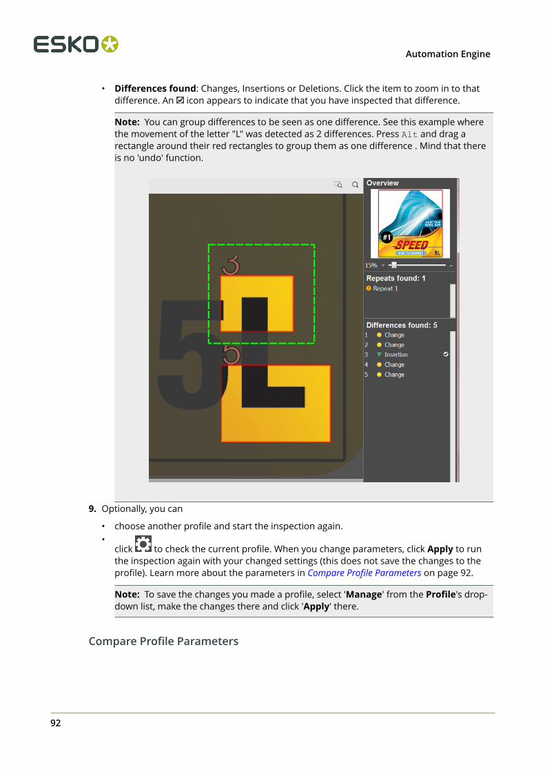
4 Automation Engine
• Differences found: Changes, Insertions or Deletions. Click the item to zoom in to thatdifference. An icon appears to indicate that you have inspected that difference.
Note: You can group differences to be seen as one difference. See this example wherethe movement of the letter "L" was detected as 2 differences. Press Alt and drag arectangle around their red rectangles to group them as one difference . Mind that thereis no 'undo' function.
9. Optionally, you can
• choose another profile and start the inspection again.•
click to check the current profile. When you change parameters, click Apply to runthe inspection again with your changed settings (this does not save the changes to theprofile). Learn more about the parameters in Compare Profile Parameters on page 92.
Note: To save the changes you made a profile, select 'Manage' from the Profile's drop-down list, make the changes there and click 'Apply' there.
Compare Profile Parameters
92
4Automation Engine
General
• Difference grouping (pixels). The radius for grouping differences together (0 to 999).
TextThis relates to text in PDFs, even when contourised. Also scans saved as PDF.
• Low contrast. Parameters typically for areas with color on color, like a black text on top ofan image.
• Minimum detection size (pixels). Ignores differences detected below this amount ofpixels.
• Maximum difference shift (pixels). Maximum allowable pixel tolerance before an itemis seen as a difference.
• Sensitivity. Sets the sensitivity to detect differences. Enter a value or use the slider.• Advanced
• Reduce image noise and imperfections. This produces a less pixelated image. Mindthat a higher value may inhibit difference detection (0 to 20).
• Correct text kerning and image shift. Reduces detection of small changes in textkerning and image shifts (0 to 5).
• High contrast. Same type of parameters as above for low contrast, but here for highcontrast areas, for example a black text on a white background.
ArtworkThese parameters are valid for all objects other than text. You can set the same type ofparameters as those for "Text", as described above.
Color
Enhanced color detection (digital). Enable this option when you are comparing digital filesand you want to use an enhanced method of detecting color differences.
• Minimum detection size (pixels). Ignores differences detected below this amount ofpixels.
• Sensitivity. Sets the sensitivity to detect differences. Enter a value or use the slider.
Repeat Detection
When comparing a file with a repeated version of that file, use these parameters to fine-tunethe detection of the repeats and their content.
• Find repeating shapes. Matches comparable images by their shape (5% to 99%).• Find repeating content. Checks how similar their content is, by checking the maximum
amount of allowable differences between repeats (5% to 99%). Mind that values greaterthan 30 may degrade the quality of repeat detection.
ScanThese parameters are relevant when the file is a scan of a printed sample.
93
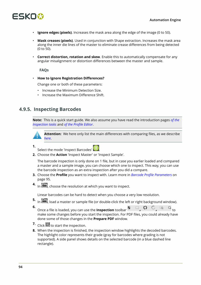
4 Automation Engine
• Ignore edges (pixels). Increases the mask area along the edge of the image (0 to 50).
• Mask creases (pixels). Used in conjunction with Shape extraction. Increases the mask areaalong the inner die lines of the master to eliminate crease differences from being detected(0 to 50).
• Correct distortion, rotation and skew. Enable this to automatically compensate for anyangular misalignment or distortion differences between the master and sample.
FAQs
• How to Ignore Registration Differences?
Change one or both of these parameters:
• Increase the Minimum Detection Size.• Increase the Maximum Difference Shift.
4.9.5. Inspecting Barcodes
Note: This is a quick start guide. We also assume you have read the introduction pages of theInspection tasks and of the Profile Editor.
Attention: We here only list the main differences with comparing files, as we describehere.
1.Select the mode 'Inspect Barcodes' .
2. Choose the Action 'Inspect Master' or 'Inspect Sample'.
The barcode inspection is only done on 1 file, but in case you earlier loaded and compareda master and a sample image, you can choose which one to inspect. This way, you can usethe barcode inspection as an extra inspection after you did a compare.
3. Choose the Profile you want to inspect with. Learn more in Barcode Profile Parameters onpage 95.
4. In , choose the resolution at which you want to inspect.
Linear barcodes can be hard to detect when you choose a very low resolution.5. In , load a master or sample file (or double-click the left or right background window).6.
Once a file is loaded, you can use the Inspection toolbar tomake some changes before you start the inspection. For PDF files, you could already havedone some of those changes in the Prepare PDF window.
7. Click to start the inspection.8. When the inspection is finished, the inspection window highlights the decoded barcodes.
The highlight color represents their grade (gray for barcodes where grading is notsupported). A side panel shows details on the selected barcode (in a blue dashed linerectangle).
94

4Automation Engine
9. Optionally, you can
• choose another profile and start the inspection again.•
click to check the current profile. When you change parameters, click Apply to runthe inspection again with your changed settings (this does not save the changes to theprofile). Learn more about the parameters in Barcode Profile Parameters on page 95.
Note: To save the changes you made a profile, select 'Manage' from the Profile's drop-down list, make the changes there and click 'Apply' there.
Barcode Profile Parameters
Note: On this page, we use the term 'linear' for 1D/Linear barcodes.
Linear
• Process
Disable this if you do not want linear barcodes inspected.
• Scan Gap Horizontal
This is the number of columns to skip between 2 scans when detecting vertically orientedlinear barcodes. A higher value increases detection speed but may reduce accuracyof detection. Adjust this parameter if there are issues with detecting vertical orientedbarcodes.
95

4 Automation Engine
• Scan Gap Vertical
This is the number of rows to skip between 2 scans when detecting horizontally orientedlinear barcodes. A higher value increases detection speed but may reduce accuracy ofdetection. Adjust this parameter if there are issues with detecting horizontal orientedbarcodes.
• Min. Quality Score
This is the minimum number of scan lines that must be decoded properly. The lower, thehigher the detection rate but also a higher chance of false positives. The default value is 5.
• Min. Vicinity Horizontal (pixels)
When a same barcode is detected twice (same type, same decoded value, sameorientation), this is the minimum horizontal distance in pixels between them to merge thedetection of the duplicate barcodes.
• Min. Vicinity Vertical (pixels)
Same as above, but the vertical distance.
• Edge Threshold
This is the minimum transition value used to detect the transition between spaces and bars.Use low values to detect high contrast barcodes and high values for low contrast codes.
• Ignore quiet zone
Enable/disable quiet zone verification for barcodes that require a quiet zone.
• Support Rotation
Enable/disable detection of non-90-degree-rotated linear barcodes (barcodes not at 0, 90,270 degree orientations).
• Support Negative Barcodes
Enable/disable detection of barcodes in (white) knockout.
• Ignore Checksum
Enable/disable checksum verification for UPC/EAN barcodes.
• Grade Output Format: An older method uses letters to grade the quality of the barcode.The ISO 15416:2016 implements a new calculation method resulting in decimal numeric
96

4Automation Engine
grades. This is more precise. The inspection report will show the grading in the format thatwas selected in this profile.
• ISO/IEC 2016 Standard (uncheck for 2000 standard). The '2000' standard sticks torounded numbers ; the '2016' one uses decimals values as well.
• Include in Grading: Data Structure
If checked this will include Data Structure grading in overall grading.
Note: The overall grading is determined by the lowest ISO grading parameter. Non ISOgrading parameters are not included in the overall grading by default.
Example: If 'Include in Grading: Data Structure' is checked and it receives a grading of D,and D is the lowest grading, then the overall grading will be D.
• Include in Grading: Quiet Zone
If checked this will include Quiet Zone grading in overall grading.
• Include in Grading: Narrow Bar
If checked this will include Narrow Bar grading in overall grading.
• Include in Grading: Wide to Narrow Ratio
If checked this will include Wide-to-Narrow-Ratio in overall grading.
• Fail Grading if BWR out of the specified range
Will fail the grading if Bar Width Reduction is out of specified range (adjustable ; default isminimum BWR set at -0.10 and maximum BWR at 0.10).
Linear Types
Enable or disable the type of linear barcodes that you want to have detected.
Data Matrix
• Process
Disable this if you do not want data matrix codes detected and inspected.
• Max. Number Codes
This is the maximum expected number of data matrix codes with unique sizes that can bedetected in an inspection. The higher this value, the slower the detection.
• Scan Gap
This is the horizontal scan gap. A higher value increases detection speed but may reduceaccuracy of detection. Adjust this parameter if there are issues with detecting data matrixbarcodes.
• Detection Level
This is the general level of the effort the algorithm spends on detection. A higher valueincreases accuracy but decreases detection.
• Edge Threshold
This is the minimum transition value used to detect the transition between light and darkcells. Use low values to detect high contrast codes and high values for low contrast codes.
97

4 Automation Engine
• Min. Size Cell (pixels)
This is the minimum size in pixels of a data matrix cell. Increase this value to remove smalldata matrix candidates and to avoid small artifacts being detected as false codes.
• Max. Size Code (pixels)
This is the maximum size of the data matrix code in pixels. Use it to remove big data matrixcandidates and speed up detection of codes. Decrease this value if larger data matrix codesare mis-detected.
• Max. Skew Angle
This is the maximum data matrix skew angle in degrees. Increase this value to allowdetection of skewed or rotated data matrix codes.
QR
• Process
Disable this if you do not want QR and Micro QR codes inspected.
• Scan Gap Horizontal
Same as mentioned above for linear barcodes.
• Scan Gap Vertical
Same as mentioned above for linear barcodes.
• Min. Quality Score
Same as mentioned above for linear barcodes.
• Edge Threshold
98

4Automation Engine
Same as mentioned above for data matrix codes.
General
• Red Light Simulation
Enable/Disable red light simulation when grading barcodes.
• Filters
Adjust these filters when there are issues with barcode detection due to noise. None = Nofiltering (default), 1x = filter one time, 2x = filter two times.
• Smooth Filter. Enable/disable smoothing the image with a Gaussian filter. The effect isblurring the image to remove noise and ease barcode detection on degraded images.
• Median Filter. Enable/disable using a Median filter to remove noise and ease barcodedetection on degraded images. This filter removes noise while preserving barcode edges.
• Open Filter. Enable/disable using an Open filter to remove small light noise such as thinstraight vertical lines on barcode and ease barcode detection.
• Close Filter. Enable/disable using a Close filter to remove small dark noise and easebarcode detection.
FAQs
Should I get the same grade results at different resolutions?Grade results can be different when done at a different resolution, especially theDecodability. Decodability measures bar/space ratios against the standard.
An example: at 600 DPI, wide barcode bars may be 10 pixels and narrow bars 5 pixels,resulting in a wide to narrow bar ratio of 2. At 300 DPI, wide barcode bars may be 5 pixels andnarrow bars 2 or 3 pixels, resulting in a different wide to narrow bar ratio. Especially when
99

4 Automation Engine
the narrowest bar is very small (1 or 2 pixels), the decodability may be different. In general, ahigher DPI produces more accurate grade results.
4.9.6. Translating Braille
Note: This is a quick start guide. We also assume you have read the introduction pages of theInspection tasks and of the Profile Editor.
Attention: We here only list the main differences with comparing files, as we describehere.
1.Select the mode 'Inspect Braille' .
2. Choose the Action 'Translate Master' or 'Translate Sample'. The braille inspection is onlydone on 1 file, but in case you already loaded a master and a sample, you can choose whichone to inspect. This way, you can use the braille inspection as an extra inspection after youdid a compare.
3. Choose the Profile you want to inspect with. For braille, the profile only defines whatlanguage the braille is written in and should be translated back to.
4. In , choose the resolution at which you want to inspect. Braille can be hard to detectwhen you choose a very low resolution.
5. In , load a master or sample file (or load them via double-clicking the left or rightbackground window).
6.Once a file is loaded, you can use the Inspection toolbar tomake some changes before you start the inspection. For PDF files, you could already havedone some of those changes in the Prepare PDF window.
Learn more about this toolbar in the pages on Comparing files on page 90.7. Click to start the translation.8. When the inspection is finished, the inspection window highlights the found braille and a
side panel shows details on the selected group of braille (in the blue dashed line rectangle).
100

4Automation Engine
Tip: In the Braille Details panel, you may need to use the slider under the Translationcharacters to read more of the translated text.
Braille Profile ParametersThe Braille Language Editor enables you to add, modify or delete braille characters of achosen language.
4.9.7. Comparing Text
Note: This is a quick start guide. We also assume you have read the introduction pages of theInspection tasks and of the Profile Editor.
Attention: We here only list the main differences with comparing files, as we describehere.
1.Select the mode 'Inspect Text' .
2. Choose the Action 'Compare'.3. Choose the Profile you want to compare with. Learn more in Text Compare Profile
Parameters on page 102.4. In , choose the resolution at which you want to inspect.
101

4 Automation Engine
5. In , load a master and load a sample file (or double-click the left or right backgroundwindow).
6.For each loaded file, you can use the Inspection toolbar tomake some changes before you start the inspection. For PDF files, you could already havedone some of those changes in the Prepare PDF window.
Learn more about this toolbar in the pages on Comparing files on page 90.7. Click to start the comparison of the text.8. When the inspection is finished, a side panel lists the found differences. Select one to zoom
in to that difference.
Text Compare Profile Parameters
Tip: Hover with your mouse over the parameters to see the tool tips with more info.
Difference Types
Indicate whether these text parameters can cause a difference or not.
Languages
These parameters are important to set the text reading order. All languages are supported indifferent orientations, but the profile requires one choice:
• Left to Right. For standard western text.
• Right to Left. For example for Arabic, Hebrew and Farsi.
• Asian. For texts where characters represent words (and often left to right).
Reading Order
Choose a Correction Level (see the tool-tips).
Templates
Using an Inspection Template enables to find smaller fragments of text that may be repeatedacross a carton. The template can also instruct to inspect only a specific section
These templates are "Quality Review of Documents" templates (QRD), a standard used in theEMA (pharma) world.
Choose between
• None.
• Carton/label.• Custom. Pick one from the offered list.
.
Advanced
102

4Automation Engine
• Table and Line processing. Choose whether you want to ignore or check underlines andtables.
• Microsoft Word Document Options. Choose whether you want to ignore any content inheaders/footers in Word documents.
4.9.8. Checking Spelling
Note: This is a quick start guide. We also assume you have read the introduction pages of theInspection tasks and of the Profile Editor.
Attention: We here only list the main differences with comparing files, as we describehere.
1.Select the mode 'Spell Check' .
2. Choose the Action 'Inspect Master' or 'Inspect Sample'. The spell check is only done on1 file, but in case you already loaded a master and a sample, you can choose which oneto inspect. This way, you can use the spell check as an extra inspection after you did acompare.
3. Choose the Profile you want to inspect with. These are dictionaries. Learn more in SpellCheck Profile Parameters on page 103.
4. In , choose the resolution at which you want to inspect.5. In , load a master or sample file (or double-click the left or right background window).6.
Once a file is loaded, you can use the Inspection toolbar tomake some changes before you start the inspection. For PDF files, you could already havedone some of those changes in the Prepare PDF window.
Learn more about this toolbar in the pages on Comparing files on page 90.7. Click to start the spelling check.8. When the check is finished, a side panel lists the found problems. Click on one to zoom in to
that problem.
Spell Check Profile ParametersWhen spell-checking, the only profile parameter is the choice of language (dictionary).
To create a custom dictionary, go to Manage in the Profile's list, select and copy a default oneand save it with a different name.
When you opened a custom dictionary, use the buttons or right-click the dialog to add/modify/delete a word. You can also first copy an external list of words and then paste that clipboardlist in this dialog.
103

4 Automation Engine
4.9.9. Shortcut Keys
Table: Shortcut Keys Global Vision Profile Editor
Key Function
CTRL/CMD - M Load master file.
CTRL/CMD - S Load sample file.
CTRL/CMD - S when inInspection mode
Opens the chosen profile.
F11 When in Inspection window of the Compare mode, navigatesto the next difference. (On Mac, you may need to switch off thesystem preferences default for F11.)
Mouse Track Wheel • On Windows: Scroll up to magnify the image. Scroll down toreduce the magnification.
• On Mac: Scroll down to magnify the image. Scroll up to reducethe magnification.
Left mouse button After taking a marquee zoom, hold down and move within thewindow to pan the view.
ALT + Select/DragRectangle
When in Inspection window of the Compare mode, to groupdifferences.
SHIFT + Select/DragRectangle
Marquee zoom.
104

5Automation Engine
5. Other QC Tasks
5.1. Check Print Rules (PRC)Print Rule Checker (PRC) is an old technology on board the Esko editor PackEdge. It checks thefile, completely or partially, for potential printing problems or violations of standard printingconventions. These checks can include insufficient line thickness, wrong halftone densities, theuse of too many inks, and various other production related issues.
The Check Print Rules (PRC) task checks the file according a rule set that you made inPackEdge. The task adds the results of its checks into the Normalized PDF file. When you thenopen this file in PackEdge, you can quickly see a full report of these checks and use dedicatedtools to quickly navigate to the parts where rules were violated.
Task options:
• Select the Ruleset from the drop-down list. These were created in PackEdge and saved in adefault central folder. Learn more about defining such rule sets in the PackEdge user guide.
Note: In this background task version of PRC, rules on 'Small Parts' and 'Close Objects' arenot checked.
• PRC Report. Enable this also get a .txt report that describes the used rule set and the foundinfringements.
• Decide what the state of the task should be when rules are violated: Task ends with awarning or Task fails .
5.2. Compare PDF
Concept and workflowThis task compares the input PDF file(s) to a reference PDF file. It creates TIFF files of eachseparation and then compares those.
You can see the found differences in a separate layer or file and also in an XML report.
105

5 Automation Engine
Note: The Inspect Artwork task also serves to compare files but is more elaborate.
The task can have these output states:
• Match: No differences were found.
• Mismatch: Differences were found.
• Error: The task itself malfunctioned (reference file was not found, no license wasavailable...).
Task Options
• Compare
• Compare With. Define the reference file with which you want to compare the input PDFfile(s).
• Select the Compare Region (of both input and reference file) within which you want tocompare. Learn more about page boxes here.
• Set the Compare Resolution for the automatically created TIFF files. Enter a valuebetween 50 and 300 ppi.
• Set the Noise Tolerance. The compare resolution defines in what detail you compare thefiles. This noise tolerance however defines how strict you want to compare: what do youconsider as a difference? If you do not want the most strict form, you can here define atolerance.
The distance in this field represents the maximum (horizontal or vertical) distancebetween isolated pixels for them to be ignored. An isolated pixel is a pixel that isdifferent in both files but that has all surrounding pixels equal in both files. The higheryou put the value, the more tolerant you are against noise. The more you allow noise,the less strict the comparison will be. The default is '0 mm' (no differences allowed, moststrict).
An example: A comparison shows 2 isolated pixels that are 10 mm apart and also 2isolated pixels that are only 2 mm apart. If you now set the noise tolerance to '5 mm',then the set of isolated pixels that are 10 mm apart will be ignored in the comparison.
• Ignore Separations. Add the names of separations to ignore during the comparison.For example for multilingual variants you may want to ignore the separation(s) thatcontain(s) text.
Tip: Double-click on a line in the canvas and use the small drop-down list to selectseparations of the ticket's input file.
• Differences
• Output in: Define the folder where you want to save the file containing the founddifferences and the report file. When you type in a name, it will be created as a subfolderof the input file.
Note: This field is thus only valid when you enable one or both of the below options.
• Select Create Differences layer if you want to add the found differences in a separatelayer.
106
5Automation Engine
Note: When page boxes are different and/or separations do not match, the task willreport a mismatch but will not create a difference layer.
In Layer File, when you use the SmartName [File], the extra layer will be added toyour input file. Alternatively, you could browse to an existing PDF file or use SmartNamesto have a new one created automatically, for example "[file]_Diff".
• Select Report differences to file to save the differences in a separate XML report file.This XML file has the extension *.comp. When the files don’t match, this report containsthe coordinates of the mismatched pixels for each separation.
Note: In the Esko editor Neo, you can insert these .comp files on top of the opened PDFto see the coordinates of where differences were found.
Tip: You can configure an extra output pin to see your report appear on its own pin.Learn more in Configuring Output Statuses.
107