quality and versatility of automatic leafcell generation
TRANSCRIPT

* 07/16/96
* ##
Quality and Versatility of Quality and Versatility of Automatic Leafcell GenerationAutomatic Leafcell Generation
Submitted: April 2004
Kaushik Jogesh PatelDepartment of Electrical Engineering
University of TennesseeKnoxville, TN 37996
Project in Lieu of ThesisProject in Lieu of Thesis

* 07/16/96
* ##
7/1/2004 2
Project Goal
To demonstrateQualityVersatility of Automatic Leafcell Generation
Abstract
This goal of this project is to demonstrate the quality and versatility of Automatic Leafcell Generation (which will be referred to as ALG).Comparing manual layouts with those generated by an ALG tool in terms of area, delay, and design time will show the quality of layouts.Versatility will be demonstrated by generating two new tech files corresponding to two additional processes.

* 07/16/96
* ##
7/1/2004 3
Design and Verification Flow
Schematic specifies desired logic and the W/L of each transistor. The resulting net-list is then simulated using Spectre.
Cadence Design Systems’® Virtuoso uses the schematic for manual layout design.
ProGenesis® - an ALG tool, accepts the same FET-level net-list as Virtuoso (after a format conversion) to generate the layout automatically.
Manual and automatic layouts are then simulated using detailed transistor models (Spectre).
Schematic(Logic-level)
Schematic(FET-level)
Custom
Layout2Layout1
Simulation
DRC/LVS
ProGenesis
Design/Verification flow
Design and verification of leaf-cells for standard-height libraries can be realized using the design flow [1] shown in the figure above.
As seen in the figure, the designer starts with a hierarchical schematic to specify the desired logic and the resulting net-list is then simulated using detailed transistor models (Spectre). Once functionally verified, the layout can be obtained using different methods. For manual design, the Cadence Design Systems [2] custom integrated circuit design bundle was used as it provides an integrated flow. ProGenesis can be used for automatic leafcellgeneration. ProGenesis accepts the same transistor-level net-list as Virtuoso (after a format conversion). Post-layout simulations are then performed for both manual and automatically generated layouts to show their results are functionally identical. The resulting layouts are also verified to have no design rule violations and to correspond to the original schematic.
* 07/16/96
* ##
7/1/2004 4
Steps in Automatic Layout Generation
ProSpin(Netlist - CEL)
Schematic(Logic-level)
Schematic(FET-level)
ProGen(CEL - AGD)
ProView
A2GD(AGD - GDS)
Import GDS
Netlist Conversion
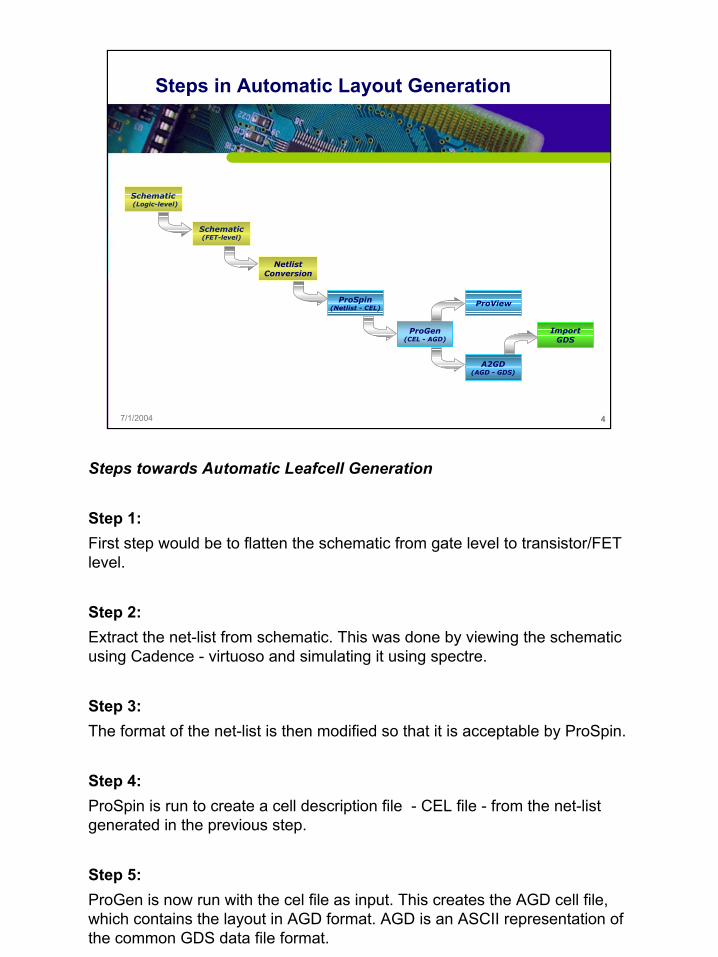
Steps towards Automatic Leafcell Generation
Step 1: First step would be to flatten the schematic from gate level to transistor/FET level.
Step 2:Extract the net-list from schematic. This was done by viewing the schematic using Cadence - virtuoso and simulating it using spectre.
Step 3:The format of the net-list is then modified so that it is acceptable by ProSpin.
Step 4:ProSpin is run to create a cell description file - CEL file - from the net-list generated in the previous step.
Step 5:ProGen is now run with the cel file as input. This creates the AGD cell file, which contains the layout in AGD format. AGD is an ASCII representation of the common GDS data file format.

* 07/16/96
* ##
7/1/2004 5
Schematic (Logic-Level)
Schematic (Logic-Level)
The figure above is an example of a logic-level schematic, identified by the NAND2 blocks that just has the input-output interfaces.

* 07/16/96
* ##
7/1/2004 6
Schematic (FET-Level)
Schematic (FET-Level)
The figure above is an example of a FET-level schematic, identified by having just flat FETs and no logic-level blocks in it.

* 07/16/96
* ##
7/1/2004 7
Netlist Format Change
\+0 (Y A 0 0) ami06N w=3e-06 l=6e-07 as=4.5e-12 ad=4.5e-12ps=6e-06 pd=6e-06 m=1 region=sat
\+1 (Y A vdd! vdd!) ami06P w=6e-06 l=6e-07 as=9e-12 ad=9e-12ps=9e-06 pd=9e-06 m=1 region=sat
.SUBCKT invx1 A Y
m0 Y A vss vss TN w=3e-06 l=6e-07
m1 Y A vdd vdd TP w=6e-06 l=6e-07
.ENDS
Original Netlist
Netlist With Format Change – to suit ALG tool
Netlist Format Change
The format of the netlist – obtained from spectre simulation – has to be changed to suit ProGenesis tools. A script that automatically does this format change is provided by ProGenesis.

* 07/16/96
* ##
7/1/2004 8
ProSpin
• ProSpin can read in a Spice net-list and convert it to the format required by the ProGen tool.
• ProSpin is also capable of accessing generators to perform other special functions when porting an old design from one process to a new process (but we have not tried this yet).
[3]
ProSpin [3]
ProSpin reads in SPICE netlists describing individual cells and produces corresponding CEL files to be read by the ProGen tool. A CEL file specifies the generators that should be called to create the final layout data and contains cell-specific information such as transistor sizes and node names.
Scaling Transistors
If the transistors need to be scaled by width or gate length, e.g., when porting netlists from an older technology, the following commands can be placed in a technology file - prospin.tcl - to get linear scaling:prospin_set option width_ratio_pfet xprospin_set option width_ratio_nfet xprospin_set option length_ratio_pfet xprospin_set option length_ratio_nfet x
Where x can be set to equal the scaling value:Widthdesired = x * widthnetlist
Setting these options allows the use of different scaling factors for p and n transistors.

* 07/16/96
* ##
7/1/2004 9
ProGen
[3]
ProGen [3]
ProGen reads in CEL files and produces physical layout based on the cell characteristics, the generators specified, and the technology-specific information (.db file) created using ProTech. After reading the CEL file, ProGen invokes the proper generators to produce a loose physical layout. ProGen then compacts this initial layout to produce a final cell that is as small as possible while conforming to all design rules and layout constraints.

* 07/16/96
* ##
7/1/2004 10
ProView
ProView
Proview is a tool to view the layout, which is in AGD file format.
* 07/16/96
* ##
7/1/2004 11
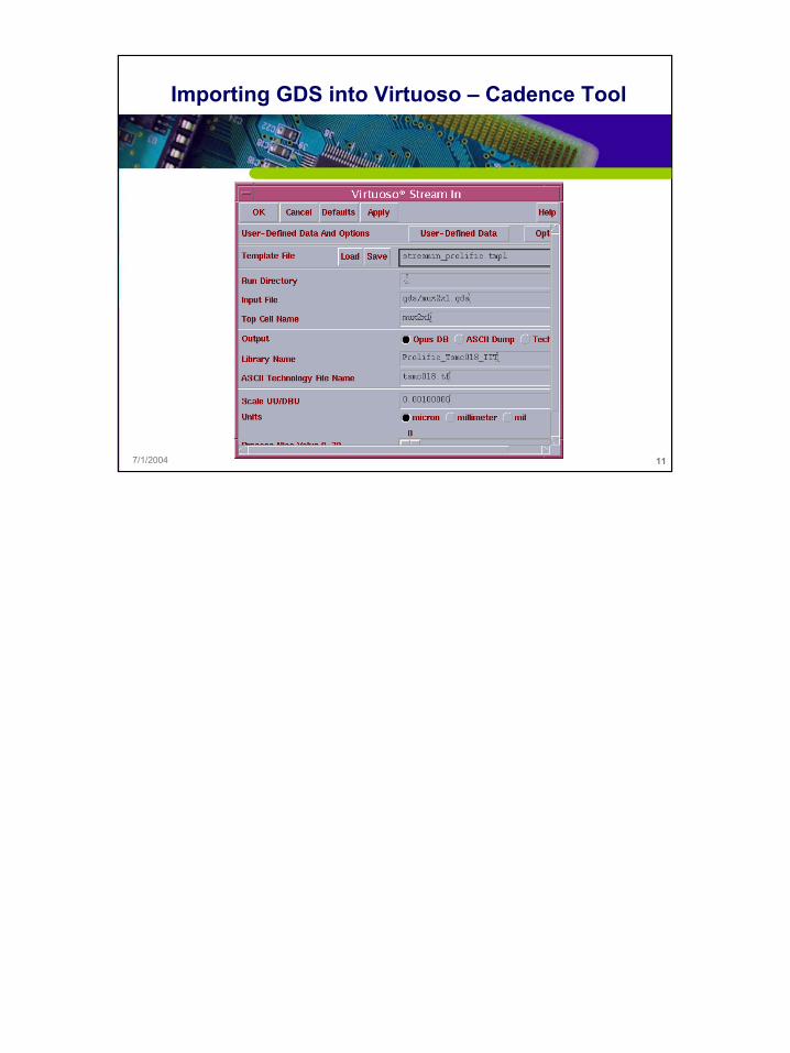
Importing GDS into Virtuoso – Cadence Tool

* 07/16/96
* ##
7/1/2004 12
Manual Layout vs. Automatic Layout (Inverter)
Manual Layout Automatic Layout

* 07/16/96
* ##
7/1/2004 13
Manual Layout vs. Automatic Layout (MUX2to1)
Manual Layout Automatic Layout

* 07/16/96
* ##
7/1/2004 14
Manual Layout vs. Automatic Layout (D Flip-Flop)
Manual Layout Automatic Layout

* 07/16/96
* ##
7/1/2004 15
Comparison Table to Determine Quality…
-3100310362247224210411-12404413211723548610-352153617231728859
-1220219416131901848-1081178020872419777-146240515051728676102584259818301660655788486113151267574
0184209118110374131562326244103789927215244239518461201
DifferenceAutoManualAutoManualTrans+NetsNumber
PercentDelayAreaComplexityCircuit
In a one-semester graduate course [4], students produced both manual and automated layouts conforming to a standard-height cell format. Typical projects for this course included counters, shift-registers, flip-flops, multipliers and dividers. Those results were used to create a comparison table of manual and automatically generated layouts. The columns in the table include circuit complexity (number of nets and FETs), area in square microns, delay in nanoseconds, design time and percent difference between the automatic and manual layouts – a custom parameter calculated by taking the product of area and delay for the automated layout minus the product of area and delay for the manual layout divided by the area-delay product for the manual case. The designs included in the table were those that met standard-height requirements, passed DRC and post-layout simulation. The measurements made were also consistent.
Comparison results showed that the manual and automated layouts differ by 15 percent or less and that ProGenesis appears to be better for more complex circuits. Since the students are novices at both using ProGenesis and in producing manual layouts, these results should not be used to make definitive judgments about the quality of the tool. However, automated layouts are generated within minutes (sometimes taking up to two hours on a Sun Enterprise 220) with almost no effort on the part of the student whereas manual layout of circuits like these generally requires at least ten hours of tedious labor.

* 07/16/96
* ##
7/1/2004 16
Versatility of ALG tool
Migration to other processes and technologies.Existing setup of ALG tool for AMI-06 technology.Setup ALG tool to generate library for TSMC-02 and AMI-04 technologies to prove versatility.(AMI-06, AMI-04, and TSMC-02 have lambda values of 0.3, 0.2, and 0.1 microns respectively)
Versatility of Automatic Leafcell Generation
It is important to cope with the continually changing technologies in the semiconductor industry. Consider a cell library designed for a particular process and technology. If the same library were to be developed for a different technology, using the ALG tool would be easier and faster compared to manual re-design.
Projects done in the graduate course mentioned earlier used the cell library targeting AMI-06 technology. MOSIS® provides scalable CMOS (SCMOS) design rules compliant to various technologies. To determine the versatility of ALG tool, cell libraries for three technologies (AMI-06, AMI-04, and TSMC-02) were developed using SCMOS_SUBM design rules with lambda of 0.3, 0.2 and 0.1.
Setup of ALG tools to automatically generate layouts targeting AMI-04 and TSMC-02 technologies (lambda of 0.20 and 0.10 microns respectively) wasnewly done, whereas existing setup targeting AMI 0.6 (lambda of 0.30) was slightly modified to generate the library consistent with standard height of an existing library done manually at IIT.
The layouts complied with standard-height format, passed DRC, and were verified through post-layout simulations. The new libraries developed through the ALG tool were then compared to that done manually by another university - IIT [6]. In all library comparisons, the cell templates- height and

* 07/16/96
* ##
7/1/2004 17
ProGenesis® Suite
Three Main ProGenesis ToolsProTechProSpinProGen
ProGen
.cel
ProSpin
Netlist
.agd
.db
ProTech
ProGenesis Suite
ProGenesis includes 3 main tools used to create layout from netlists: ProTech, ProSpin, and ProGen.
The detailed explanation of each tool is given later.

* 07/16/96
* ##
7/1/2004 18
ProTech
ProGen
.cel
ProSpin
Netlist
.agd
.db
ProTech
ProTech [3]
ProTech is the tool used to configure fabrication technology specifications, design styles, and layer information. ProTech is used to enter or modify the following types of information:
• Design Options: Transistor layout and folding, compaction and routing options.
• Design Rules: Mandatory and preferred rules specified by the fab.
• Layer Data: Specify GDS layer data and text.
• Cell Template: Cell height, well tie behavior, and rail and well sizes.
Having an existing example of a ‘.db’ file setup for AMI-06 technology, there were some changes made for other technologies. The following major values were changed:
As shown in the figure, under cell template tab, the cell height and routing grids in both x and y direction were changed according to the standard height of cells at IIT, and with the lambda of other technology.
Unlike other values which would work if scaled according to lambda (since it is

* 07/16/96
* ##
7/1/2004 19
Results to add to UT’s Library
A cell library for TSMC-02 technology corresponding to the one in IITA cell library for AMI-04 technology corresponding to the one in IITA cell library for AMI-06 technology corresponding to the one in IIT

* 07/16/96
* ##
7/1/2004 20
Manual IIT Layout vs. Automatic Layout (MUX2to1; AMI-06)
Manual Layout Automatic Layout

* 07/16/96
* ##
7/1/2004 21
Comparison Table to Determine Versatility (AMI-06)
01261262882881312515615036028813229694288288143
137984432360184
2625625410808643970181181288288116318117621621695
DifferenceAutoIITAutoIITTrans+NetsNumber
PercentDelayAreaComplexityCircuit

* 07/16/96
* ##
7/1/2004 22
Manual IIT Layout vs. Automatic Layout (MUX2to1; TSMC-02)
Manual Layout Automatic Layout

* 07/16/96
* ##
7/1/2004 23
Comparison Table to Determine Versatility (TSMC-02)
0565632321312563634032132048483232143
-245464040184
610110310496397078783232116
297072322495
DifferenceAutoIITAutoIITTrans+NetsNumber
PercentDelayAreaComplexityCircuit

* 07/16/96
* ##
7/1/2004 24
Automatic Layout (MUX2to1; AMI-06 and AMI-04)
AMI-06 Layout AMI-04 Layout

* 07/16/96
* ##
7/1/2004 25
References
[1] EWME 2004 – “Teaching Custom And Automated Cell Design”- Donald W. Bouldin, Chandra Tan and Kaushik J. Patel[2] Cadence Design Systems, http://www.cadence.com[3] ProGenesis Documentation[4] ECE 651, University of Tennessee, http://vlsi1.engr.utk.edu/ece/bouldin_courses/[5] Prolific, Inc., http://www.prolificinc.com[6] MOSIS, http://www.mosis.org[7] ECE Department at IIT, http://www.ece.iit.edu/~cad/scells/

* 07/16/96
* ##
Thank You !
Thank You !