quadrant machinists handbook - alro.com machinists handbook machining plastics made easy...
TRANSCRIPT

Find us online @quadrantepp
QUADRANTMACHINISTSHANDBOOKMachining Plastics Made Easy
8 0 0 - 3 6 6 - 0 3 0 0 quadrantplastics.com Brought to you by:

CONTENTS TABLE OF
Fabrication Guidelines .....................................................................................
Machinability ....................................................................................................
Drilling Guidelines ............................................................................................ Troubleshooting - Drilling ................................................................................
Sawing Guidelines ...........................................................................................
End Milling/ Slotting Guidelines ...................................................................... Face Milling ......................................................................................................
Troubleshooting - Turning & Boring ................................................................
Troubleshooting - Cutting Off ..........................................................................
Turning Guidelines ...........................................................................................
Annealing .........................................................................................................
Air Annealing Guidelines .................................................................................Diagrams .......................................................................................................... Conversions .....................................................................................................Notes .................................................................................................................
11131517
3
1921222325
3127
3335
9OVERVIEWPLASTICS
“YOUR SOURCE FOR ENGINEERING PLASTICS” ISO 9001: 2008 Certified
• Over $10 million in stock at Alro Plastics• Same day cutting and shipping for quick delivery
Please Return To:
Name:
Company:
Dept:
Address:
City:
State:
Zip:
Phone:
Email:
2
BROAD INVENTORY
OFFERING:/ Engineering Plastic Rods from 1/8” diameter to 15 3/4” diameter
/ Engineering Plastic Sheets from 1/8” to 7” thick
800-877-2576 | alroplastics.com

3
The following guidelines are presented for those machinists not familiar with the machining characteristics of plastics. They are intended as guidelines only and may not represent the most optimum conditions for all parts. The troubleshooting quick reference guides in this booklet should be used to correct undesirable surface finishes or material responses during machining operations. All Quadrant materials are stress relieved to ensure highest degree of machinability and dimensional stability. However, the relative softness of plastics (compared to metals) generally results in greater difficulty maintaining tight tolerances during and after machining. A good rule of thumb for tolerances of plastic parts is +/- .001˝ per inch of dimension although tighter tolerances are possible with very stable, reinforced materials.
WHEN MACHINING QUADRANT STOCK SHAPES REMEMBER...
4
• Thermal expansion is up to 10x greater with plastics than metals
• Plastics lose heat more slowly than metals, so avoid localized overheating
• Softening (and melting) temperatures of plastics are much lower than metals
• Plastics are much more elastic than metals
Because of these differences, you may wish to experiment with fixtures, tool materials, angles, speeds and feed rates to obtainoptimum results.
GETTING STARTED
• Positive tool geometries with ground peripheries are recommended
• Carbide tooling with ground top surfaces is suggested for optimum tool life and surfaces finish. Polycrystalline diamond tooling provides optimum surface finish when machining Duratron® PBI.
• Use adequate chip clearance to prevent clogging
• Adequately support the material to restrict deflection away from the cutting tool
COOLANTS
Coolants are generally not required for most machining operations (not including drilling and parting off). However, for optimum surface finishes and close tolerances, non-aromatic, water soluble coolants are suggested. Spray mists and pressurized air are very effective means of cooling the cutting interface. General purpose petroleum based cutting fluids, although suitable for many metals and plastics, may contribute to stress cracking of amorphous plastics such as Quadrant® PC 1000, Quadrant® PSU, Duratron® U1000 PEI, and Quadrant® PPSU.
MACHINING TIPS
Coolants are strongly suggested during drilling operations, especially with notch sensitive materials such as Ertalyte® PET-P, Duratron® PAI, Duratron® PBI and glass or carbon reinforced products.
In addition to minimizing localized part heat-up, coolants prolong tool life. Two (flood) coolants suitable for most plastics are Trim E190 and Trim Sol LC SF (Master Chemical Corporation – Perrysburg, OH).
3 4
FABRICATION GUIDELINES
800-877-2576 | alroplastics.com

THREADING & TAPPINGThreading should be done by single point using a carbide insert and taking four to five 0.001˝ passes at the end. Coolant usage is suggested.
For tapping, use the specified drill with a two flute tap. Remember to keep the tap clean of chip build-up. Use of a coolant during tapping is also suggested.
Use of a coated tap can improve the toughness of threads in a notch sensitive material.
MILLINGSufficient fixuring allows fast table travel and high spindle speeds when end milling plastics. When face milling, use positive geometry cutter bodies.
SAWINGBand sawing is versatile for straight, continuous curves or irregular cuts. Table saws are convenient for straight cuts and can be used to cut multiple thicknesses and thicker cross sections up to 4˝ with adequate horsepower. Saw blades should be selected based upon material thickness and surface finish desired.
5 6
SAWING TIPS• Rip and combination blades with a 0º tooth rake and 3º to 10º tooth set are best for general sawing in order to reduce frictional heat.
• Hollow ground circular saw blades without set will yield smooth cuts up to 3/4˝ thickness.
• Tungsten carbide blades wear well and provide optimum surface finishes.
FABRICATION GUIDELINES
800-877-2576 | alroplastics.com

The insulating characteristics of plastics require consideration during drilling operations, especially when hole depths are greater than twice the diameter.
Small diameter holes (1/32˝ to 1˝ diameter)
High speed steel twist drills are generally sufficient for small holes. To improve swarf removal, frequent pulling out (peck drilling) is suggested. A slow spiral (low helix) drill will allow for better swarf removal.
Large diameter holes (1˝ diameter & larger)
A slow spiral (low helix) drill or general purpose drillbit ground to 118º point angle with 9º to 15º lip clearance is recommended. The lip rake should be ground (dubbed off) and the web thinned.
It is generally best to drill a pilot hole (maximum 1/2˝ diameter) using 600 to 1,000 rpm and a positive feed of 0.005˝ to 0.015˝ per revolution. Avoid hand feeing because of the drill grabbing which can result in microcracks forming. Secondary drilling at 400 to 500 rpm at 0.008 to 0.020˝ per revolution is required to expand the hole to larger diameters.
A two step process using both drilling and boring can be use on notch sensitive materials such as Ertalyte® PET-P and glass reinforced materials. This minimizes heat build-up and reduces the risk of cracking.
7 8
TURNINGTurning operations require inserts with positive geometries and ground peripheries. Ground peripheries and polished top surfaces generally reduce material build-up on the insert, improving the attainable surface finish. A fine grained C-2 carbide is generally best for turning operations.
1. Drill a 1˝ diameter hole using an insert drill at 500 to 800 rpm with a feed rate of 0.005 to 0.015˝ per revolution.
2. Bore the hole to final dimensions using a boring bar with carbide insert with 0.015˝ to 0.030˝ radii at 500 to 1,000 rpm and a feed rate of 0.005 to 0.101˝ per revolution.
DRILLINGTIP:
800-877-2576 | alroplastics.com

9 10
Acet
ron®
GP
POM
-C
1Ac
etro
n® PO
M-H
, Ace
tron®
AF
1Ac
etro
n® A
F Bl
end
1
Dura
tron®
CU6
0 PB
I 10
Dura
tron®
T42
03 P
AI
5Du
ratro
n® T
4301
PAI
5
Dura
tron®
T45
01 P
AI
6Du
ratro
n® T
4503
PAI
6
Dura
tron®
T45
40 P
AI
6Du
ratro
n® T
5530
PAI
8
Dura
tron®
U10
00 P
EI &
U23
00 P
EI
3, 7
Erta
lyte
® P
ET-P
2
Erta
lyte
® T
X PE
T-P
2 Fl
uoro
sint
® M
T01
3Fl
uoro
sint
® 5
00 P
TFE
1Fl
uoro
sint
® 2
07 P
TFE
1Fl
uoro
sint
® H
PV
1
Ketro
n® 1
000
PEEK
5
Ketro
n® G
F30
PEEK
7
Ketro
n® C
F30
PEEK
7
Ketro
n® H
PV P
EEK
6
Nyla
tron®
MC9
01 P
A6 &
MC9
07 P
A6
1Ny
latro
n®
GS
PA66
& G
SM P
A6
1Ny
latro
n®
GSM
Blu
e PA
6, N
SM P
A6 &
703
XL
2
Quad
rant
® N
ylon
101
PA6
6 1
Quad
rant
® P
C 10
00
2Qu
adra
nt®
PSU
3
Quad
rant
® P
PSU
3
Tech
tron®
CM
PSB
G PP
S 5
Tech
tron®
CM
PSG
F 7
Tech
tron®
PPS
3
Tech
tron®
HPV
PPS
3
225
POM
-C
130
0 PE
T 2
410C
PE
I 4
420
PEI
442
0V
PEI
448
0 PE
EK
449
0 HR
PE
EK
450
0 HR
PT
FE
252
0 HR
PA
I 4
CMP
LL5
PET
2CM
P XL
20
PAI
5
ww
w.q
uadr
antp
last
ics.
com
SEM
ITRO
N M
ATER
IALS
Follo
w g
uide
lines
for m
ost s
imila
r bas
e re
sin
B
ASE
RESI
N
MAT
ERIA
L
RELA
TIVE
MAC
HINA
BILI
TY
(1
to 1
0:
1 =
Eas
iest
)
MACHINABILITY
800-877-2576 | alroplastics.com

Smaller diameter holes • High speed twist drills • Peck drill suggested
Larger diameter holes • Drill pilot hole • Use slow speed spiral drills or inserted drills
Proteus® PP, Quadrant® PC 1000, Quadrant® PSU, Quadrant® PPSU and Duratron® PEI based materials
Fluorosint® PTFE (1) based materials
NominalHoleDiameter
0.007 - 0.0150.015 - 0.0250.020 - 0.050
0.007 - 0.0150.015 - 0.0250.020 - 0.050
0.002 - 0.0050.015 - 0.0250.020 - 0.050
0.007 - 0.0150.015 - 0.0250.020 - 0.050
0.007 - 0.0150.015 - 0.0250.020 - 0.050
1/2" or larger
0.015 - 0.025
FeedIn./Rev.
Symalit®
PVDF and ECTFE based materials
Ertalyte® PET-Pbased materials
Duratron® PAI and Duratron® PI based materials
Duratron® PBIbased materials
Techtron® PPS based materials
TIVAR® UHMW-PE, Nylatron® PA6, Acetron® POM based materials
0.002 - 0.0050.004 - 0.0080.008 - 0.012
Ketron® PEEK based materials
1/16" to 1/4"1/2" to 3/4"1" to >2"
0.007 to 0.0150.015 to 0.0250.020 to 0.050
1/16" to 1/4"1/2" to 3/4"1" to >2"
1/16" to 1/4"1/2" to 3/4"1" to >2"
1/16" to 1/4"1/2" to 3/4"1" to >2"
1/16" to 1/4"1/2" to 3/4"1" to >2"
0.002 - 0.0050.015 - 0.0250.020 - 0.050
1/16" to 1/4"1/2" to 3/4"1" to >2"
1/16" to 1/4"1/2" to 3/4"1" to >2"
1/16" to 1/4"1/2" to 3/4"1" to >2"
(1) For Fluorosint® MT01 PTFE contact Quadrant’s Technical Service Team
11 12
TIP
DRILLING GUIDELINES
TIP:
800-877-2576 | alroplastics.com

13 14
DIFF
ICUL
TY
C
OMM
ON C
AUSE
1. In
corr
ectly
sha
rpen
ed d
rill
2. In
suffi
cien
t cle
aran
ce3.
Fee
d to
o he
avy
1. W
rong
type
dril
l2.
Inco
rrec
tly s
harp
ened
dril
l3.
Fee
d to
o lig
ht4.
Dul
l dril
l5.
Web
too
thic
k6.
Not
pec
k dr
illin
g
1. F
eed
too
heav
y2.
Cle
aran
ce to
o gr
eat
3. T
oo m
uch
rake
(thi
n w
eb a
s de
scrib
ed)
1. T
oo m
uch
clea
ranc
e2.
Fee
d lig
ht3.
Dril
l ove
rhan
g to
o gr
eat
4. T
oo m
uch
rake
(thi
n w
eb a
s de
scrib
ed)
1. F
eed
too
heav
y2.
Dril
l not
cen
tere
d3.
Dril
l gro
und
off-
cent
er
1. D
rill g
roun
d of
f-ce
nter
2. W
eb to
o th
ick
3. In
suffi
cien
t cle
aran
ce4.
Fee
d ra
te to
o he
avy
5. P
oint
ang
le to
o gr
eat
1. D
ull d
rill
2. T
oo m
uch
clea
ranc
e3.
Poi
nt a
ngle
too
smal
l
1. F
eed
too
heav
y2.
Spi
ndle
spe
ed to
o sl
ow3.
Dril
l ent
ers
next
pie
ce to
o fa
r4.
Cut
-off
tool
leav
es n
ib,
w
hich
defl
ects
dril
l5.
Web
too
thic
k6.
Dril
l spe
ed to
o he
avy
at s
tart
7. D
rill n
ot m
ount
ed o
n ce
nter
8. D
rill n
ot s
harp
ened
cor
rect
ly
1. D
ull c
ut-o
ff to
ol2.
Dril
l doe
s no
t pas
s co
mpl
etel
y th
roug
h pi
ece
1. F
eed
too
light
of d
rill
2. S
pind
le s
peed
too
fast
3. In
suffi
cien
t lub
ricat
ion
from
coo
lant
TAPE
RED
HOLE
BURN
T OR
MEL
TED
SURF
ACE
CHIP
PING
OF
SURF
ACES
CHAT
TER
FEED
MAR
KS O
R SP
IRAL
LIN
ES O
N IN
SIDE
DIA
MET
ER OV
ERSI
ZE H
OLES
UNDE
RSIZ
E HO
LES
HOLE
S NO
T CO
NCEN
TRIC
BURR
AT
CUT-
OFF
RAPI
D DU
LLIN
G OF
DRI
LL
DRILLING NOTES
800-877-2576 | alroplastics.com

15 16
Proteus® PP, Quadrant® PC 1000, Quadrant® PSU,
Quadrant® PPSU and Duratron® PEI based materials
Fluorosint® PTFE (1) based materials
Symalit®
PVDF and ECTFE based materials
Ertalyte® PET-Pbased materials
Duratron® PAI and Duratron® PI based materials
Duratron® PBIbased materials
Techtron® PPS based materials
TIVAR® UHMW-PE,Nylatron® PA6, Acetron® POM based materials
Ketron® PEEK based materials
(1) For Fluorosint® MT01 PTFE contact Quadrant’s Technical Service Team
Tooth Form
MaterialThickness
PitchTeeth/In.
Band SpeedsFt./Min.
Precision Butress
10-14 6 3 3
2,500 2,000 1,5003,000
<.5" >3.0".5"-1.0" 1.0"-3.0"
Precision Butress
10-14 6 3 3
3,500 3,000 2,5004,000
<.5" >3.0".5"-1.0" 1.0"-3.0"
Precision Butress
4,300 3,500 3,0005,000
10-14 6 3 3
<.5" >3.0".5"-1.0" 1.0"-3.0"
Precision Butress
10-14 6 3 3
3,500 3,000 2,5004,000
<.5" >3.0".5"-1.0" 1.0"-3.0"
3,500 3,000 2,5004,000
Precision Butress
10-14 6-8 3 3
<.5" >3.0".5"-1.0" 1.0"-3.0"
2,5003,000
Precision
10-14 6-8
<.5" .5"-1.0"
1,5002,000
3 3
1.0"-3.0" >3.0"
Butress
4,300 3,500 3,0005,000
Precision Butress
10-14 6-8 3 3
<.5" >3.0".5"-1.0" 1.0"-3.0"
Precision Butress
4,300 3,500 3,0005,000
10-14 6-8 3 3
<.5" >3.0".5"-1.0" 1.0"-3.0"
Precision Butress
3,000 1,500
10 10
.375"-1.0" 1.0"-2.0"
SAWING GUIDELINES
800-877-2576 | alroplastics.com
17 18(1) For Fluorosint® MT01 PTFE contact Quadrant’s Technical Service Team
Depthof Cut
RecommendCarbide
Speed,Feet/Min.
Feed,In./Tooth
0.2500.050
270 - 450300 - 500
0.002, 0.003, 0.005,0.008, 0.001, 0.002, 0.004
1/4", 1/2", 3/4", 1", 2",1/4", 1/2", 3/4"
0.2500.050
270 - 450300 - 500
0.002, 0.003, 0.005,0.008, 0.001, 0.002, 0.004
1/4", 1/2", 3/4", 1", 2",1/4", 1/2", 3/4"
0.2500.050
270 - 450300 - 500
0.002, 0.003, 0.005,0.008, 0.001, 0.002, 0.004
1/4", 1/2", 3/4", 1", 2",1/4", 1/2", 3/4"
0.1500.060
500 - 750
0.0200.005
1/4", 1/2", 3/4", 1", 2",1/4", 1/2", 3/4"
0.2500.050
270 - 450300 - 500
0.002, 0.003, 0.005,0.008, 0.001, 0.002, 0.004
1/4", 1/2", 3/4", 1", 2",1/4", 1/2", 3/4"
0.1500.060
500 - 700550 - 750
0.0100.005
1/4", 1/2", 3/4", 1", 2",1/4", 1/2", 3/4"
0.1500.060
1300 - 15001500 - 2000
0.0200.005
1/4", 1/2", 3/4", 1", 2",1/4", 1/2", 3/4"
0.035
500 - 800
0.006 - 0.035
1/4", 1/2", 3/4", 1", 2",1/4", 1/2", 3/4"
0.015
250 - 350
0.002 - 0.006
1/4", 1/2", 3/4", 1", 2",1/4", 1/2", 3/4"
Proteus® PP, Quadrant® PC 1000, Quadrant® PSU,
Quadrant® PPSU andDuratron® PEI based materials
Fluorosint® PTFE (1) based materials
Symalit®
PVDF and ECTFE based materials
Ertalyte® PET-Pbased materials
Duratron® PAI and Duratron® PI based materials
Duratron® PBIbased materials
Techtron® PPS based materials
TIVAR® UHMW-PE,Nylatron® PA6, Acetron® POM
based materialsKetron® PEEK based materials
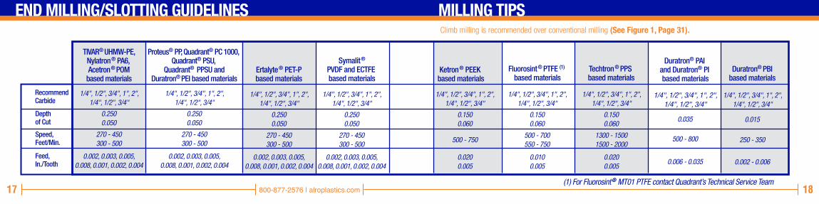
Climb milling is recommended over conventional milling (See Figure 1, Page 31).
END MILLING/SLOTTING GUIDELINES MILLING TIPS
800-877-2576 | alroplastics.com

19 20
500 - 700550 - 750
0.1500.060
(1) For Fluorosint® MT01 PTFE contact Quadrant’s Technical Service Team
Depthof Cut
Speed,Feet/Min.
Feed,In./Tooth
Proteus® PP, Quadrant® PC 1000, Quadrant® PSU,
Quadrant® PPSU and Duratron® PEI based materials
Fluorosint® PTFE (1) based materials
Symalit®PVDF and ECTFE based materials
Ertalyte® PET-Pbased materials
Duratron® PAI and Duratron® PI based materials
Duratron® PBIbased materials
Techtron® PPS based materials
TIVAR® UHMW-PE,Nylatron® PA6, Acetron® POM
based materialsKetron® PEEK based materials
0.1500.060
1300 - 15001500 - 2000
0.0200.005
0.1500.060
1300 - 15001500 - 2000
0.0200.005
0.1500.060
1300 - 15001500 - 2000
0.0200.005
0.1500.060
0.0200.005
500 - 750
0.1500.060
270 - 450300 - 500
0.0200.005
0.0100.005
0.035
500 - 800
0.006 - 0.035
0.015
250 - 350
0.002 - 0.006
0.1500.060
1300 - 15001500 - 2000
0.0200.005
FACE MILLING (C-2, Carbide Tool) MILLING TIPSClimb milling is recommended over conventional milling (See Figure 1, Page 31).
800-877-2576 | alroplastics.com

21 22
Mel
ted
Surfa
ce1.
Du
ll to
ol2.
In
suffi
cien
t sid
e cl
eara
nce
3.
Insu
ffici
ant c
oola
nt s
uppl
y
1.
Feed
too
heav
y2.
To
ol im
prop
erly
sha
rpen
ed3.
Cu
tting
edg
e no
t hon
ed
1.
Tool
rubs
dur
ing
its re
treat
2.
Burr
on
poin
t of t
ool
1.
Poin
t ang
le to
o gr
eat
2.
Tool
not
per
pend
icul
ar to
spi
ndle
3.
Tool
def
lect
ing
4.
Feed
too
heav
y5.
To
ol m
ount
ed a
bove
or
be
low
cen
ter
1.
Poin
t ang
le n
ot g
reat
eno
ugh
2.
Tool
dul
l3.
Fe
ed to
o he
avy
1.
No c
ham
ber b
efor
e cu
t-of
f
diam
eter
2.
Dull
tool
Roug
h Fi
nish
Spira
l Mar
ks
Conc
ave
or
Co
nvex
Sur
face
s
Nib
s or
Bur
rsat
Cut
-off
Poin
t
Burr
s on
Out
side
Diam
eter
Mel
ted
Surfa
ce
Roug
h Fi
nish
Chat
ter
Burr
s at
Edg
e of
Cut
Crac
king
or
Chip
ping
of
Corn
ers
1.
Tool
dul
l or h
eel r
ubbi
ng2.
In
suffi
cien
t sid
e cl
eara
nce
3.
Feed
rate
too
slow
4.
Spin
dle
spee
d to
o fa
st
1.
Feed
too
heav
y2.
In
corr
ect c
lear
ance
ang
les
3.
Shar
p po
int o
n to
ol
(slig
ht n
ose
radi
us re
quire
d)4.
To
ol n
ot m
ount
ed o
n ce
nter
1.
No c
ham
fer p
rovi
ded
at
sh
arp
corn
ers
2.
Dull
tool
3.
Insu
ffici
ent s
ide
clea
ranc
e4.
Le
ad a
ngle
not
pro
vide
d on
to
ol (t
ool s
houl
d ea
se o
ut o
f
cut g
radu
ally,
not
sud
denl
y)
1.
Too
muc
h po
sitiv
e ra
ke o
n to
ol2.
To
ol n
ot e
ased
into
cut
(to
ol s
udde
nly
hits
wor
k)3.
Du
ll to
ol4.
To
ol m
ount
ed b
elow
cen
ter
5.
Shar
p po
int o
n to
ol
(slig
ht n
ose
radi
us re
quire
d)
1.
Too
muc
h no
se ra
dius
on
tool
2.
Tool
not
mou
nted
sol
idly
3.
Mat
eria
l not
sup
porte
d pr
oper
ly4.
W
idth
of c
ut to
o w
ide
(use
2 c
uts)
DIFF
ICUL
TY
COM
MON
CAU
SE
DIFF
ICUL
TY
COM
MON
CAU
SE
TURNING & BORING CUTTING OFF NOTESNOTES
800-877-2576 | alroplastics.com

23 24
Inserts with positive geometries and ground peripheries• Use Recommended Turning Tooling Geometry (See Figure 2, page 32).
Turning Guidelines (C-2, Carbide Tool)
www.quadrantplastics.comNOTESTurning Tips
Inserts with positive geometries and ground peripheries • Use Recommended Turning Tooling Geometry (See Diagram 2, page 32).
Nylatron®, Nylon (PA), Acetron®,Polycarbonate (PC), Polysulfone (PSU) and Ultem® PEI based materials
Fluorosint® PTFE basedmaterials
Depthof Cut
.150" deep cut
.025" deep cut.150" deep cut.025" deep cut
.150" deep cut
.025" deep cut
500 - 600600 - 700
350 - 500500 - 600
600 - 1000600 - 700
.010 - .015
.004 - .007.010 - .015.003 - .008
0.150" deep cut0.025" deep cut
350 - 500500 - 600
0.010 - 0.0150.003 - 0.008
.010 - .016
.004 - .007
.025" deep cut
150 - 225
.002 - .006
SpeedFeet/Min.
Feed,In./Min.
Ketron® PEEK based
materials
Ertalyte®
PET based materials
Torlon® (PAI) based
materialsCelazole® PBI
Techtron®
PPS based materials
0.015 - 0.25
(1) For Fluorosint® MT01 PTFE contact Quadrant’s Technical Service Team
Depthof Cut
Speed,Feet/Min.
Feed,In./Rev
Proteus® PP, Quadrant® PC 1000, Quadrant® PSU,
Quadrant® PPSU and Duratron® PEI based materials
Fluorosint® PTFE (1) based materials
Symalit®
PVDF and ECTFE based materials
Ertalyte® PET-Pbased materials
Duratron® PAI and Duratron® PI based materials
Duratron®
PBIbased materials
Techtron® PPS based materials
TIVAR® UHMW-PE,Nylatron® PA6, Acetron® POM based materials
Ketron® PEEK based materials
0.150" deep cut0.025" deep cut
500 - 600600 - 700
0.010 - 0.0150.004 - 0.007
0.150" deep cut0.025" deep cut
600 - 1000600 - 700
0.010 - 0.0160.004 - 0.007
0.150" deep cut0.025" deep cut
500 - 600600 - 700
0.010 - 0.0150.004 - 0.007
0.150" deep cut0.025" deep cut
100 - 300250 - 500
0.010 - 0.0200.005 - 0.010
0.025" deep cut
300 - 800
0.004 - 0.025
0.025" deep cut
150 - 225
0.002 - 0.006
0.150" deep cut0.025" deep cut
500 - 600600 - 700
0.010 - 0.0150.004 - 0.007
0.150" deep cut0.025" deep cut
500 - 600600 - 700
0.010 - 0.0150.004 - 0.007
TURNING GUIDELINES (C-2, Carbide Tool) TURNING TIPS
800-877-2576 | alroplastics.com

25 26
WHEN SHOULD PARTS BE ANNEALED AFTER MACHINING TO ENSURE OPTIMUM PART PERFORMANCE?Experience has shown us that very few machined plastic parts require annealing after machining to meet dimensional or performance requirements.
All Quadrant stock shapes are annealed using a proprietary stress relieving cycle to minimize any internal stresses that may result from the manufacturing process. This assures you that the material will remain dimensionally stable during and after machining.
Machined-in stress can reduce part performance and lead to premature part failure. To prevent machined-in stress, it is important to identify the causes.
IMPROVED CHEMICAL RESISTANCEPolycarbonate, polysulfone, and Duratron® PEI, like many amorphous (transparent) plastics may be annealed to minimize stress crazing. Duratron® PAI also benefits from post machining annealing. Annealing finished parts becomes more important as machining volume increases. Annealing after machining reduces ˝machined-in˝ stresses that can contribute to premature failure.
BETTER FLATNESS AND TIGHTER TOLERANCE CAPABILITYExtremely close–tolerance parts requiring precision flatness and non-symmetrical contour sometimes require intermediate annealing between machining operations. Improved flatness can be attained by rough machining, annealing and finish machining with a very light cut. Balanced machining on both sides of the shape centerline can also help prevent warpage.
IMPROVED WEAR RESISTANCEExtruded or injection molded Duratron®
PAI parts that require high PV’s or the lowest possible wear factor benefit from an additional cure after machining. This curing process optimizes the wear properties. Only Duratron® PAI benefits from such a cycle.
MACHINED-IN STRESS IS CREATED BY:
• Using dull or improperly designed tooling
• Excessive heat – generated from inappropriate speeds and feed rates
• Machining away large volumes of material – usually from one side of the stock shape
To reduce the potential for machined-in stress, review the fabrication guidelines for the specific material. Recognize that guidelines change as the material type changes.
BENEFITS OF POST-MACHINING ANNEALING
ANNEALING POST MACHINING
800-877-2576 | alroplastics.com

27 28
Finish machining of critical dimensions should be performed after annealing.
IMPORTANT: Annealing cycles have been generalized to apply to a majority of machined parts. Changes in heat up and hold time may be possible if cross sections are thin. Parts should be fixtured during annealing to prevent distortion.
Type 6 Nylons
Type 6/6 Nylons
Ertalyte® PET-P
Acetron® GP POM-C
Acetron® POM-H
Quadrant® PC 1000
Quadrant® PSU
4 hours to 300˚ F
4 hours to 350˚ F
4 hours to 350˚ F
4 hours to 310˚ F
4 hours to 320˚ F
4 hours to 275˚ F
4 hours to 330˚ F
30 minutes per 1/4” Thickness
30 minutes per 1/4” Thickness
30 minutes per 1/4” Thickness
30 minutes per 1/4” Thickness
30 minutes per 1/4” Thickness
30 minutes per 1/4” Thickness
30 minutes per 1/4” Thickness
50˚ F per hour
50˚ F per hour
50˚ F per hour
50˚ F per hour
50˚ F per hour
50˚ F per hour
50˚ F per hour
Oil or Nitrogen
Oil or Nitrogen
Oil or Nitrogen
Nitrogen or Air
Nitrogen or Air
Air
Air
• Ensure parts are fixtured to desired shape or flatness. • Do not unfixture until parts have completed entire cycle and are cool to the touch. • Do not take short-cuts.
MATERIAL HEAT UP HOLD COOL DOWN ENVIRONMENTTIP:
POST MACHINING AIR ANNEALING GUIDELINES
Type 6 Nylons
Type 6/6 Nylons
Ertalyte® PET-P
Acetron® GP POM-C
Acetron® POM-H
Quadrant® PC 1000
Quadrant® PSU
4 hours to 300˚ F
4 hours to 350˚ F
4 hours to 350˚ F
4 hours to 310˚ F
4 hours to 320˚ F
4 hours to 275˚ F
4 hours to 330˚ F
30 minutes per 1/4” Thickness
30 minutes per 1/4” Thickness
30 minutes per 1/4” Thickness
30 minutes per 1/4” Thickness
30 minutes per 1/4” Thickness
30 minutes per 1/4” Thickness
30 minutes per 1/4” Thickness
50˚ F per hour
50˚ F per hour
50˚ F per hour
50˚ F per hour
50˚ F per hour
50˚ F per hour
50˚ F per hour
Oil or Nitrogen
Oil or Nitrogen
Oil or Nitrogen
Nitrogen or Air
Nitrogen or Air
Air
Air
• Ensure parts are fixtured to desired shape or flatness. • Do not unfixture until parts have completed entire cycle and are cool to the touch. • Do not take short-cuts.
MATERIAL HEAT UP HOLD COOL DOWN ENVIRONMENT
800-877-2576 | alroplastics.com

29 30
• Ensure parts are fixtured to desired shape or flatness. • Do not unfixture until parts have completed entire cycle and are cool to the touch. • Do not take short-cuts.
MATERIAL
Quadrant® PPSUDuratron® PEI
Duratron® PAI
Duratron® PI
Techtron® PPS
Ketron® PEEK
4 hours to 390˚ F
4 hours to 350˚ F
4 hours to 300˚ F4 hours to 375˚ F4 hours to 300˚ F4 hours to 420˚ F4 hours to 470˚ F4 hours to 500˚ F4 hours to 300˚ F4 hours to 450˚ F4 hours to 600˚ F
30 minutes per 1/4” thickness
30 minutes per 1/4” thickness60 minutes per 1/4” thickness60 minutes per 1/4” thickness
60 minutes per 1/4” thickness60 minutes per 1/4” thickness
1 day1 day1 day
3 to 10 days
50˚ F per hour
50˚ F per hour
50˚ F per hour
50˚ F per hour
50˚ F per hour
Nitrogen or Air
Air
Air
Air
Air
HEAT UP HOLD COOL DOWN ENVIRONMENT
Finish machining of critical dimensions should be performed after annealing.
IMPORTANT: Annealing cycles have been generalized to apply to a majority of machined parts. Changes in heat up and hold time may be possible if cross sections are thin. Parts should be fixtured during annealing to prevent distortion.
TIP:POST MACHINING AIR ANNEALING GUIDELINES
• Ensure parts are fixtured to desired shape or flatness. • Do not unfixture until parts have completed entire cycle and are cool to the touch. • Do not take short-cuts.
MATERIAL
Quadrant® PPSUDuratron® PEI
Duratron® PAI
Duratron® PI
Techtron® PPS
Ketron® PEEK
4 hours to 390˚ F
4 hours to 350˚ F
4 hours to 300˚ F4 hours to 375˚ F4 hours to 300˚ F4 hours to 420˚ F4 hours to 470˚ F4 hours to 500˚ F4 hours to 300˚ F4 hours to 450˚ F4 hours to 600˚ F
30 minutes per 1/4” thickness
30 minutes per 1/4” thickness60 minutes per 1/4” thickness60 minutes per 1/4” thickness
60 minutes per 1/4” thickness60 minutes per 1/4” thickness
1 day1 day1 day
3 to 10 days
50˚ F per hour
50˚ F per hour
50˚ F per hour
50˚ F per hour
50˚ F per hour
Nitrogen or Air
Air
Air
Air
Air
HEAT UP HOLD COOL DOWN ENVIRONMENT
800-877-2576 | alroplastics.com

31 32
CUTTERROTATION
TABLE FEED
CUTTERROTATION
TABLE FEED
CLIMB MILLING CONVENTIONAL MILLING
5˚
5˚
3˚30'
3˚30' 11̊
CPG
CLIMB MILLING VS. CONVENTIONAL MILLING RECOMMENDED TURNING TOOLING GEOMETRY1
FIG 2
FIG
800-877-2576 | alroplastics.com

33 34
FRAC
TION
S D
ECIM
AL
M
M
.015
6.0
312
.046
8.0
625
.078
1.0
937
.109
3.1
25.1
406
.156
2.1
718
.187
5.2
031
.218
7.2
343
.250
.265
6.2
812
.296
8.3
125
.328
1.3
437
.359
3.3
75.3
906
.406
2.4
218
.437
5.4
531
.468
7.4
843
.500
.515
6.5
312
.546
8.5
625
.578
1 .5
937
.609
3.6
25.6
406
.656
2.6
781
.687
5.7
031
.718
7.7
343
.750
.765
6.7
812
.796
8.8
125
.828
1.8
437
.859
3.8
75.8
906
.906
2.9
218
.937
5.9
531
.968
7.9
843
1.00
0
1/64
1/32
3/64
1/16
5/64
3/32
7/64 1/8
9/64
5/32
11/6
43/
1613
/64
7/32
15/6
41/
417
/64
9/32
19/6
45/
1621
/64
11/3
223
/64
3/8
25/6
413
/32
27/6
47/
1629
/64
15/3
231
/64
1/2
33/6
417
/32
35/6
49/
16
37/6
419
/32
39/6
45/
841
/64
21/3
243
/64
11/1
645
/64
23/3
247
/64
3/4
49/6
425
/32
51/6
413
/16
53/6
427
/32
55/6
47/
857
/64
29/3
259
/64
15/1
661
/64
31/3
263
/64
1
0.
396
0.
793
1.
190
1.
587
1.
984
2.
381
2.
778
3.
175
3.
571
3.
968
4.
365
4.
762
5.
159
5.
556
5.
953
6.
350
6.
746
7.
143
7.
540
7.
937
8.
334
8.
731
9.
128
9.
525
9.
921
10.
318
10.
715
11.
112
11.
509
11.
906
12.
303
12.
700
13.
096
13.
493
13.
890
14.
287
14.6
84 1
5.08
1 1
5.47
8 1
5.87
5 1
6.27
1 1
6.66
8 1
7.06
5 1
7.46
2 1
7.85
9 1
8.25
6 1
8.65
3 1
9.05
0 1
9.44
6 1
9.84
3 2
0.24
0 2
0.63
7 2
1.03
4 2
1.43
1 2
1.82
8 2
2.22
5 2
2.62
1 2
3.01
8 2
3.41
5 2
3.81
2 2
4.20
9 2
4.60
6 2
5.00
3 2
5.40
0
ww
w.q
uadr
antp
last
ics.
com
NOTESCONVERSIONS
800-877-2576 | alroplastics.com

35 36
NOTES
800-877-2576 | alroplastics.com

THERMOPLASTICS & THERMOSETSPlastics are commonly described as being either a thermoplastic (meltable) or a thermoset (non meltable). Thermoset materials such as phenolic and epoxy were developed as early as 1900 and were some of the earliest ˝high volume˝ plastics. Both thermoplastic and thermoset stock shapes are available for machined parts, although thermoplastic stock shapes are much more commonly used today. Their ease of fabrication, self-lubricating characteristics, and broad size and shape availability make thermoplastics ideal for bearing and wear parts as well as structural components.
ALRO PLASTICS LOCATIONS
37
MICHIGANJACKSON (HEADQUARTERS)2218 Enterprise Jackson, MI 49204-0927Local: (517) 787-5500Toll Free: (800) 877-2576Fax: (517) 787-6380
FLORIDACLEARWATER 10585 47th Street N. Clearwater, FL 33762Local: (727) 573-1480Toll Free: (877) 968-9980Fax: (727) 573-1632
GRAND RAPIDS4150 Broadmoor SEGrand Rapids, MI 49512Local: (616) 656-2820Toll Free: (888) 877-2576Fax: (616) 656-2828
LOUISVILLE5620 Shepherdsville RoadLouisville, KY 40228-1014Local: (502) 968-9980Toll Free: (877) 968-9980Fax: (502) 968-5530
LIVONIA34401 Schoolcraft RoadLivonia, MI 48150Toll Free: (800) 877-2576Fax: (517) 787-6380
KENTUCKY
800-877-2576 | alroplastics.com

alroplastics.com
All statements, technical information and recommendations contained in this publication are presented in good faith, based upon tests believed to be reliable and practical field experience. The reader is cautioned, however, that Quadrant Engineering Plastic Products does not guarantee the accuracy or completeness of this information and it is the customer’s responsibility to determine the suitability of Quadrant’s products in any given application. Acetron, CleanStat, Corzan, Duraspin, Duratron, Erta, Ertacetal, Ertalene, Ertalon, Ertalyte, Extreme Materials, Fluorosint, Ketron, MC, Monocast, Novatron, Nylatrack, Nylatron, Polypenco, Proteus, Sanalite, Semitron, Symalit, Techtron, TIVAR, Ultrawear and Vibratuf are registered trademarks of the Quadrant group of companies. * Classix is a registered trademark of Invibio Ltd. Corp.* Rulon is a registered trademark of Saint Gobain Performance Plastics * Torlon and Udel are registered trademarks of Solvay Advanced Polymers * Vespel, Delrin and Teflon are registered trademarks of E.I. DuPont * Noryl and Lexan are registered trademarks of GE Plastics* Celazole is a registered trademark of PBI Performance Products, Inc. * Kynar is a registered trademark of Arkema* Corzan is a registered trademark of Noveon
Design and content created by Quadrant Engineering Plastic Products and are protected by copyright law. Copyright © 2015 The Quadrant group of companies. All rights reserved.
00831 | 2.25.15 | 3,000