quad-thopter: tailless flapping wing robot with 4 pairs · pdf filequad-thopter: tailless...
TRANSCRIPT
Quad-thopter: Tailless Flapping Wing Robotwith 4 Pairs of Wings
Christophe De Wagter∗and Matej Karasek†and Guido de Croon‡
Micro Air Vehicle Laboratory, Delft University of Technology, Kluyverweg 1, The Netherlands
ABSTRACT
We present a novel design of a tailless flappingwing Micro Air Vehicle (MAV), which uses fourindependently driven pairs of flapping wings inorder to fly and perform agile maneuvers. Thewing pairs are arranged such that differentialthrust generates the desired roll and pitch mo-ments, similar to a quadrotor. Moreover, twopairs of wings are tilted clockwise and two pairsof wings anti-clockwise. This allows the MAVto generate a yaw moment. We have constructedthe design and performed multiple flight testswith it, both indoors and outdoors. These testshave shown the vehicle to be capable of agile ma-neuvers, and able to cope with wind gusts. Themain advantage is that the proposed design is rel-atively simple to produce, and yet has the capa-bilities expected of tailless flapping wing MAVs.
1 INTRODUCTION
Flying animals remain unrivaled when it comes to theirflying skills and flight characteristics. Hummingbirds canhover and maneuver in narrow spaces to feed and then sub-sequently fly hundreds of kilometers when migrating [1].Besides the energy and sensory processing aspects, a greatdeal of the advantages of flying animals over current MicroAir Vehicles (MAVs) are attributed to their way of propul-sion. Flapping wings are predicted to achieve higher lift co-efficients than conventional MAV designs, especially whenscaled further down towards insect scales. In addition, theyare expected to have a higher energy efficiency when flying athigher speeds, extending range and duration of the flight [2].
Despite considerable efforts - and successes [3, 4] - in thelast few decades, the dominating MAV types are still rotor-craft, fixed wings or recently combinations of both[5, 6]. Amain reason for this is the difficulty of producing a flappingwing MAV that fulfills some of the promises of animal flight.
On the one hand, there is a large class of ‘tailed’ flap-ping wing MAVs, which goes back to rubber-band flappingwing vehicles designed in the 19th century [7]. Flappingwing MAVs such as ‘small bird’ [8], ‘big bird’ [9], or the
∗Email address: [email protected]†Email address: [email protected]‡Email address: [email protected]
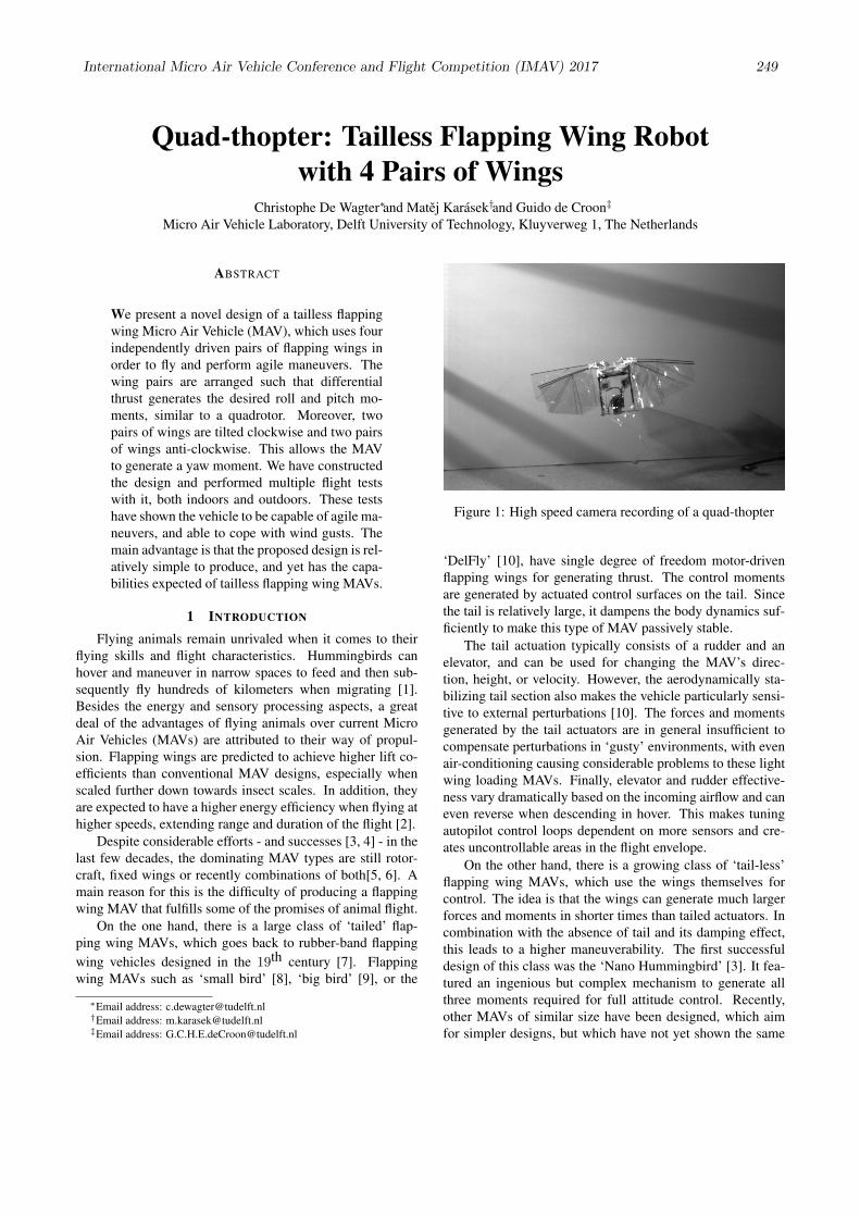
Figure 1: High speed camera recording of a quad-thopter
‘DelFly’ [10], have single degree of freedom motor-drivenflapping wings for generating thrust. The control momentsare generated by actuated control surfaces on the tail. Sincethe tail is relatively large, it dampens the body dynamics suf-ficiently to make this type of MAV passively stable.
The tail actuation typically consists of a rudder and anelevator, and can be used for changing the MAV’s direc-tion, height, or velocity. However, the aerodynamically sta-bilizing tail section also makes the vehicle particularly sensi-tive to external perturbations [10]. The forces and momentsgenerated by the tail actuators are in general insufficient tocompensate perturbations in ‘gusty’ environments, with evenair-conditioning causing considerable problems to these lightwing loading MAVs. Finally, elevator and rudder effective-ness vary dramatically based on the incoming airflow and caneven reverse when descending in hover. This makes tuningautopilot control loops dependent on more sensors and cre-ates uncontrollable areas in the flight envelope.
On the other hand, there is a growing class of ‘tail-less’flapping wing MAVs, which use the wings themselves forcontrol. The idea is that the wings can generate much largerforces and moments in shorter times than tailed actuators. Incombination with the absence of tail and its damping effect,this leads to a higher maneuverability. The first successfuldesign of this class was the ‘Nano Hummingbird’ [3]. It fea-tured an ingenious but complex mechanism to generate allthree moments required for full attitude control. Recently,other MAVs of similar size have been designed, which aimfor simpler designs, but which have not yet shown the same
International Micro Air Vehicle Conference and Flight Competition (IMAV) 2017 249
maneuverability as the Nano Hummingbird and, at the sametime, suffer from very limited flight endurance of several tensof seconds at best [11, 12, 13]. The smallest type of flappingwing MAV of this class is the well-known ‘Robobee’ [14],which for now requires the energy source to be off-board.
Although current tail-less flapping wing MAVs are clos-ing in on the ideal set by nature, none of them are yet bothable to perform real flight missions and at the same time rel-atively easy to construct.
To broaden the field of application of flapping wingMAVs, a light and simple wing actuation mechanism wouldbe needed that can quickly create large attitude control mo-ments in all three axes. Based on this idea, we present in thispaper a new tailless flapping wing MAV design, referred toas a ‘quad-thopter’. The design is similar to a quadrotor, inthe sense that it uses the thrust of four wing pairs to do thrustvectoring (Figure 1). It is also reminiscent of the very early‘Mentor’ design [15], which also had four wing pairs for fly-ing. However, that design used a single main actuator drivingthe 4 wings at the same flapping frequency. The control reliedupon control surfaces interacting with the wake of the flap-ping wings, which had rather low effectiveness, limiting thecontrollability of the system. Instead, the ‘quad-thopter’ candrive all wings independently from zero to maximal thrust,which can generate significant roll and pitch moments, andthe flapping planes of diagonally opposing wing-pairs aretilted with respect to each other for yaw controllability.
The quad-thopter design proposed in this paper representsa close-to-optimal choice in the design space consisting ofthe magnitude of the generated control moments, the con-trol bandwidth, and the weight, size and energy requirementsof the actuators. In addition, the quad-thopter is relativelyeasy to construct with widely available current-day technol-ogy, and has a flight time of 9 minutes or more, dependingon the flight regime. Hence, it is suitable for real-world mis-sions.
In Section 2, we discuss current flapping wing designsand actuators in more detail, in order to get a better under-standing of the difficulties involved in tailless flapping wingMAV design. Then, in Section 3, we present the new de-sign. We study the body’s vibrations in Section 4 and theless evident yaw moment generation in Section 5. We de-scribe the flight characteristics in Section 6, showing picturesof the flapping wing MAV in flight and providing links toflight footage. Finally, we draw conclusions in Section 7.
2 TAIL-LESS FLAPPING WING
2.1 Moment generationMost ornithopter designs use a tail, which provides pas-
sive aerodynamic stabilization and typically carries also con-ventional actuated control surfaces. When the tail is removed,active stabilization becomes necessary and some mechanismis required to create the 3 moments needed to orient and sta-bilize the platform.
(a) (b)
(c) (d)
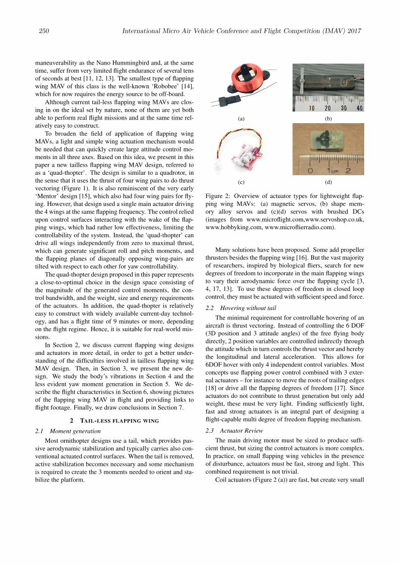
Figure 2: Overview of actuator types for lightweight flap-ping wing MAVs: (a) magnetic servos, (b) shape mem-ory alloy servos and (c)(d) servos with brushed DCs(images from www.microflight.com,www.servoshop.co.uk,www.hobbyking.com, www.microflierradio.com).
Many solutions have been proposed. Some add propellerthrusters besides the flapping wing [16]. But the vast majorityof researchers, inspired by biological fliers, search for newdegrees of freedom to incorporate in the main flapping wingsto vary their aerodynamic force over the flapping cycle [3,4, 17, 13]. To use these degrees of freedom in closed loopcontrol, they must be actuated with sufficient speed and force.
2.2 Hovering without tail
The minimal requirement for controllable hovering of anaircraft is thrust vectoring. Instead of controlling the 6 DOF(3D position and 3 attitude angles) of the free flying bodydirectly, 2 position variables are controlled indirectly throughthe attitude which in turn controls the thrust vector and herebythe longitudinal and lateral acceleration. This allows for6DOF hover with only 4 independent control variables. Mostconcepts use flapping power control combined with 3 exter-nal actuators – for instance to move the roots of trailing edges[18] or drive all the flapping degrees of freedom [17]. Sinceactuators do not contribute to thrust generation but only addweight, these must be very light. Finding sufficiently light,fast and strong actuators is an integral part of designing aflight-capable multi degree of freedom flapping mechanism.
2.3 Actuator Review
The main driving motor must be sized to produce suffi-cient thrust, but sizing the control actuators is more complex.In practice, on small flapping wing vehicles in the presenceof disturbance, actuators must be fast, strong and light. Thiscombined requirement is not trivial.
Coil actuators (Figure 2 (a)) are fast, but create very small
250 International Micro Air Vehicle Conference and Flight Competition (IMAV) 2017
moments, which makes them suitable only for actuation ofconventional tail control surfaces. Shape memory alloys (Fig-ure 2 (b)) have shown high strength at minimal weight, but areslow, fragile and create minimal deflections, that need to beamplified.
Most servos consists of small brushed motors with a re-duction gearbox and include a position feedback mechanismwith a potentiometer (Figure 2 (c)) or magnet and hall effectsensor (Figure 2 (d)). The gear ratio can be altered to changethe speed versus force, but to increase both, a larger and heav-ier motor is needed; its size can even come close to the oneof the main flapping motor. In contrast with the main motorwhich runs all the time, actuator motors are used very ineffi-ciently and only work part of the time.
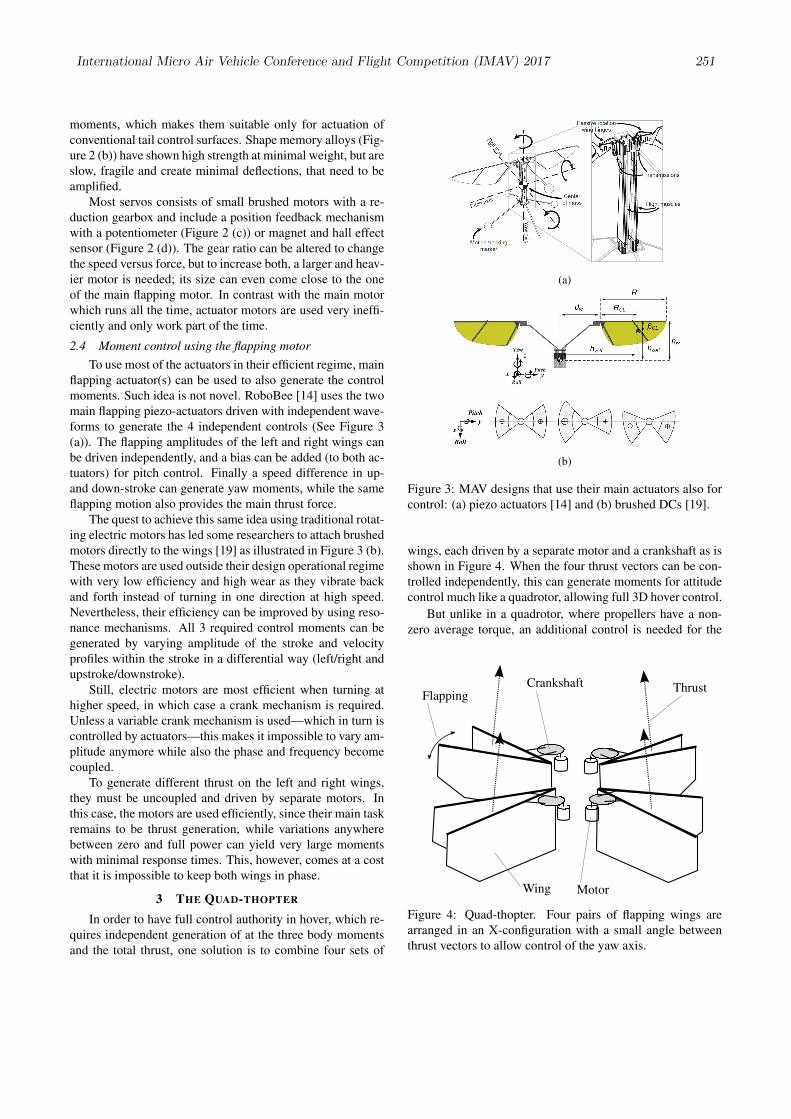
2.4 Moment control using the flapping motorTo use most of the actuators in their efficient regime, main
flapping actuator(s) can be used to also generate the controlmoments. Such idea is not novel. RoboBee [14] uses the twomain flapping piezo-actuators driven with independent wave-forms to generate the 4 independent controls (See Figure 3(a)). The flapping amplitudes of the left and right wings canbe driven independently, and a bias can be added (to both ac-tuators) for pitch control. Finally a speed difference in up-and down-stroke can generate yaw moments, while the sameflapping motion also provides the main thrust force.
The quest to achieve this same idea using traditional rotat-ing electric motors has led some researchers to attach brushedmotors directly to the wings [19] as illustrated in Figure 3 (b).These motors are used outside their design operational regimewith very low efficiency and high wear as they vibrate backand forth instead of turning in one direction at high speed.Nevertheless, their efficiency can be improved by using reso-nance mechanisms. All 3 required control moments can begenerated by varying amplitude of the stroke and velocityprofiles within the stroke in a differential way (left/right andupstroke/downstroke).
Still, electric motors are most efficient when turning athigher speed, in which case a crank mechanism is required.Unless a variable crank mechanism is used—which in turn iscontrolled by actuators—this makes it impossible to vary am-plitude anymore while also the phase and frequency becomecoupled.
To generate different thrust on the left and right wings,they must be uncoupled and driven by separate motors. Inthis case, the motors are used efficiently, since their main taskremains to be thrust generation, while variations anywherebetween zero and full power can yield very large momentswith minimal response times. This, however, comes at a costthat it is impossible to keep both wings in phase.
3 THE QUAD-THOPTER
In order to have full control authority in hover, which re-quires independent generation of at the three body momentsand the total thrust, one solution is to combine four sets of
(a)
(b)
Figure 3: MAV designs that use their main actuators also forcontrol: (a) piezo actuators [14] and (b) brushed DCs [19].
wings, each driven by a separate motor and a crankshaft as isshown in Figure 4. When the four thrust vectors can be con-trolled independently, this can generate moments for attitudecontrol much like a quadrotor, allowing full 3D hover control.
But unlike in a quadrotor, where propellers have a non-zero average torque, an additional control is needed for the
Crankshaft
MotorWing
FlappingThrust
Figure 4: Quad-thopter. Four pairs of flapping wings arearranged in an X-configuration with a small angle betweenthrust vectors to allow control of the yaw axis.
International Micro Air Vehicle Conference and Flight Competition (IMAV) 2017 251
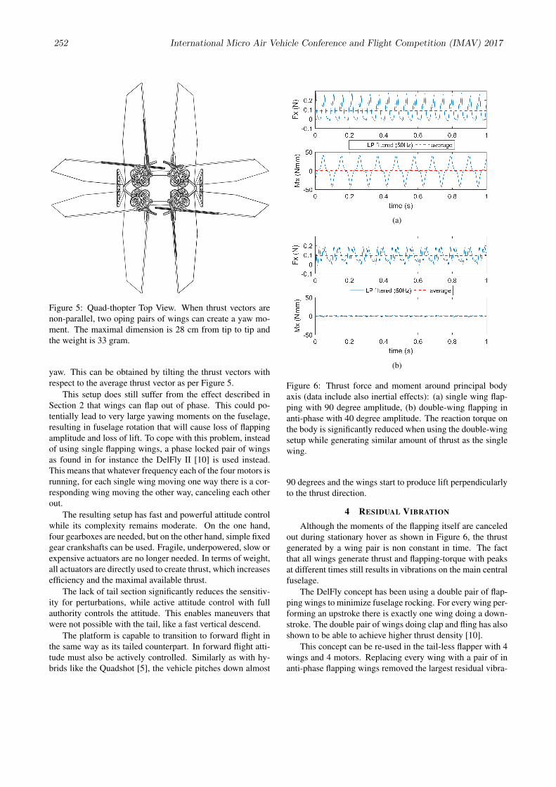
Figure 5: Quad-thopter Top View. When thrust vectors arenon-parallel, two oping pairs of wings can create a yaw mo-ment. The maximal dimension is 28 cm from tip to tip andthe weight is 33 gram.
yaw. This can be obtained by tilting the thrust vectors withrespect to the average thrust vector as per Figure 5.
This setup does still suffer from the effect described inSection 2 that wings can flap out of phase. This could po-tentially lead to very large yawing moments on the fuselage,resulting in fuselage rotation that will cause loss of flappingamplitude and loss of lift. To cope with this problem, insteadof using single flapping wings, a phase locked pair of wingsas found in for instance the DelFly II [10] is used instead.This means that whatever frequency each of the four motors isrunning, for each single wing moving one way there is a cor-responding wing moving the other way, canceling each otherout.
The resulting setup has fast and powerful attitude controlwhile its complexity remains moderate. On the one hand,four gearboxes are needed, but on the other hand, simple fixedgear crankshafts can be used. Fragile, underpowered, slow orexpensive actuators are no longer needed. In terms of weight,all actuators are directly used to create thrust, which increasesefficiency and the maximal available thrust.
The lack of tail section significantly reduces the sensitiv-ity for perturbations, while active attitude control with fullauthority controls the attitude. This enables maneuvers thatwere not possible with the tail, like a fast vertical descend.
The platform is capable to transition to forward flight inthe same way as its tailed counterpart. In forward flight atti-tude must also be actively controlled. Similarly as with hy-brids like the Quadshot [5], the vehicle pitches down almost
(a)
(b)
Figure 6: Thrust force and moment around principal bodyaxis (data include also inertial effects): (a) single wing flap-ping with 90 degree amplitude, (b) double-wing flapping inanti-phase with 40 degree amplitude. The reaction torque onthe body is significantly reduced when using the double-wingsetup while generating similar amount of thrust as the singlewing.
90 degrees and the wings start to produce lift perpendicularlyto the thrust direction.
4 RESIDUAL VIBRATION
Although the moments of the flapping itself are canceledout during stationary hover as shown in Figure 6, the thrustgenerated by a wing pair is non constant in time. The factthat all wings generate thrust and flapping-torque with peaksat different times still results in vibrations on the main centralfuselage.
The DelFly concept has been using a double pair of flap-ping wings to minimize fuselage rocking. For every wing per-forming an upstroke there is exactly one wing doing a down-stroke. The double pair of wings doing clap and fling has alsoshown to be able to achieve higher thrust density [10].
This concept can be re-used in the tail-less flapper with 4wings and 4 motors. Replacing every wing with a pair of inanti-phase flapping wings removed the largest residual vibra-
252 International Micro Air Vehicle Conference and Flight Competition (IMAV) 2017
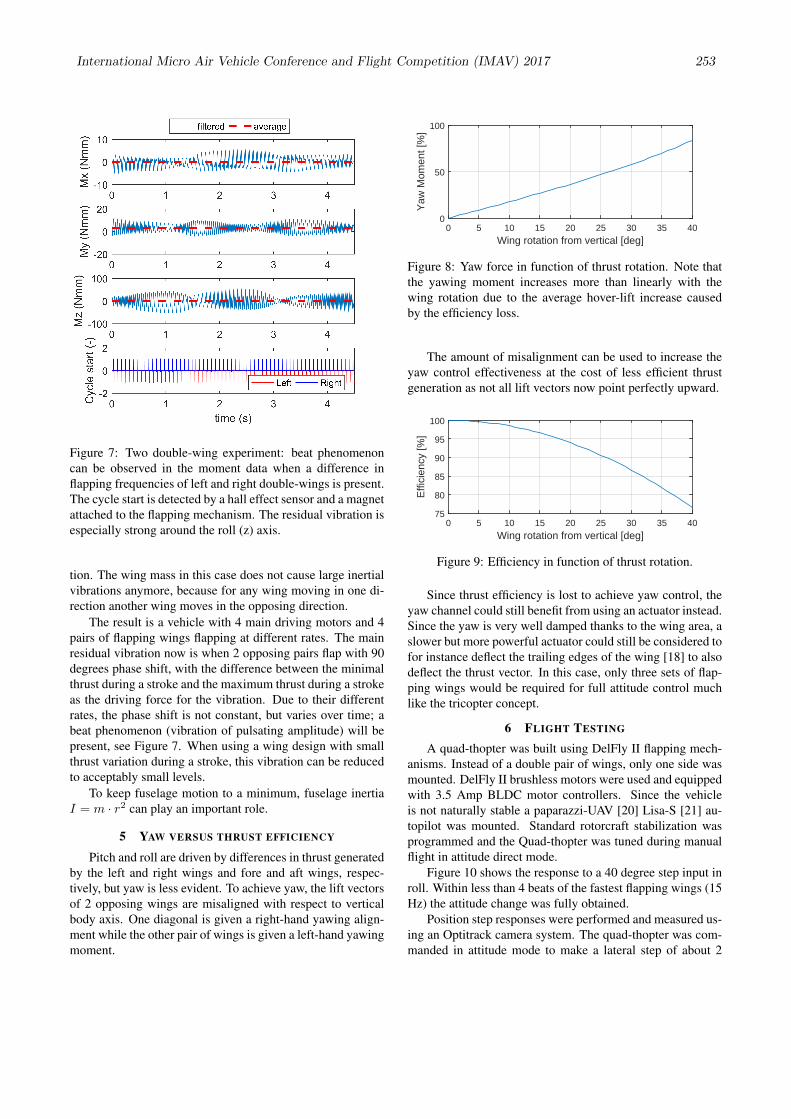
Figure 7: Two double-wing experiment: beat phenomenoncan be observed in the moment data when a difference inflapping frequencies of left and right double-wings is present.The cycle start is detected by a hall effect sensor and a magnetattached to the flapping mechanism. The residual vibration isespecially strong around the roll (z) axis.
tion. The wing mass in this case does not cause large inertialvibrations anymore, because for any wing moving in one di-rection another wing moves in the opposing direction.
The result is a vehicle with 4 main driving motors and 4pairs of flapping wings flapping at different rates. The mainresidual vibration now is when 2 opposing pairs flap with 90degrees phase shift, with the difference between the minimalthrust during a stroke and the maximum thrust during a strokeas the driving force for the vibration. Due to their differentrates, the phase shift is not constant, but varies over time; abeat phenomenon (vibration of pulsating amplitude) will bepresent, see Figure 7. When using a wing design with smallthrust variation during a stroke, this vibration can be reducedto acceptably small levels.
To keep fuselage motion to a minimum, fuselage inertiaI = m · r2 can play an important role.
5 YAW VERSUS THRUST EFFICIENCY
Pitch and roll are driven by differences in thrust generatedby the left and right wings and fore and aft wings, respec-tively, but yaw is less evident. To achieve yaw, the lift vectorsof 2 opposing wings are misaligned with respect to verticalbody axis. One diagonal is given a right-hand yawing align-ment while the other pair of wings is given a left-hand yawingmoment.
Wing rotation from vertical [deg]0 5 10 15 20 25 30 35 40
Yaw
Mom
ent [
%]
0
50
100
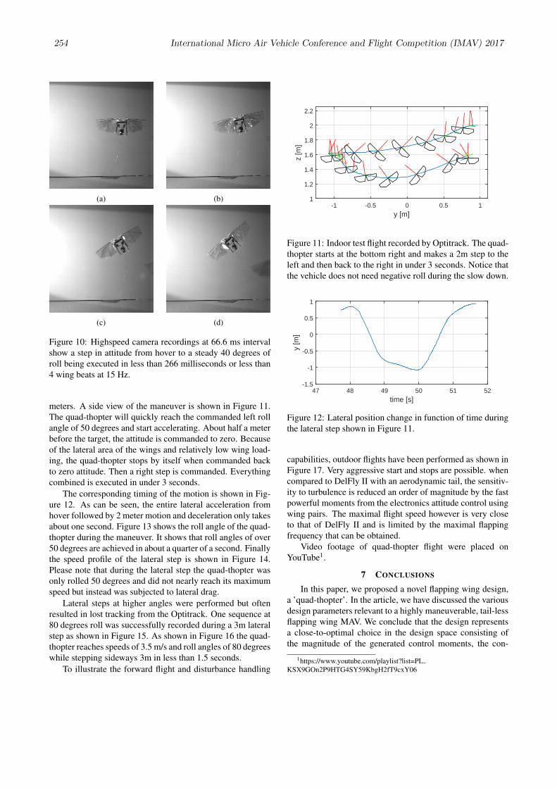
Figure 8: Yaw force in function of thrust rotation. Note thatthe yawing moment increases more than linearly with thewing rotation due to the average hover-lift increase causedby the efficiency loss.
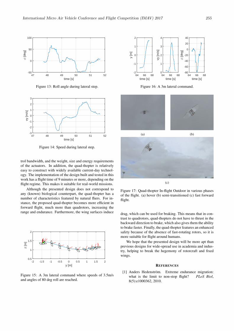
The amount of misalignment can be used to increase theyaw control effectiveness at the cost of less efficient thrustgeneration as not all lift vectors now point perfectly upward.
Wing rotation from vertical [deg]0 5 10 15 20 25 30 35 40
Effi
cien
cy [%
]
75
80
85
90
95
100
Figure 9: Efficiency in function of thrust rotation.
Since thrust efficiency is lost to achieve yaw control, theyaw channel could still benefit from using an actuator instead.Since the yaw is very well damped thanks to the wing area, aslower but more powerful actuator could still be considered tofor instance deflect the trailing edges of the wing [18] to alsodeflect the thrust vector. In this case, only three sets of flap-ping wings would be required for full attitude control muchlike the tricopter concept.
6 FLIGHT TESTING
A quad-thopter was built using DelFly II flapping mech-anisms. Instead of a double pair of wings, only one side wasmounted. DelFly II brushless motors were used and equippedwith 3.5 Amp BLDC motor controllers. Since the vehicleis not naturally stable a paparazzi-UAV [20] Lisa-S [21] au-topilot was mounted. Standard rotorcraft stabilization wasprogrammed and the Quad-thopter was tuned during manualflight in attitude direct mode.
Figure 10 shows the response to a 40 degree step input inroll. Within less than 4 beats of the fastest flapping wings (15Hz) the attitude change was fully obtained.
Position step responses were performed and measured us-ing an Optitrack camera system. The quad-thopter was com-manded in attitude mode to make a lateral step of about 2
International Micro Air Vehicle Conference and Flight Competition (IMAV) 2017 253
(a) (b)
(c) (d)
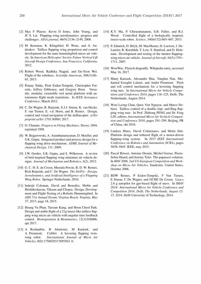
Figure 10: Highspeed camera recordings at 66.6 ms intervalshow a step in attitude from hover to a steady 40 degrees ofroll being executed in less than 266 milliseconds or less than4 wing beats at 15 Hz.
meters. A side view of the maneuver is shown in Figure 11.The quad-thopter will quickly reach the commanded left rollangle of 50 degrees and start accelerating. About half a meterbefore the target, the attitude is commanded to zero. Becauseof the lateral area of the wings and relatively low wing load-ing, the quad-thopter stops by itself when commanded backto zero attitude. Then a right step is commanded. Everythingcombined is executed in under 3 seconds.
The corresponding timing of the motion is shown in Fig-ure 12. As can be seen, the entire lateral acceleration fromhover followed by 2 meter motion and deceleration only takesabout one second. Figure 13 shows the roll angle of the quad-thopter during the maneuver. It shows that roll angles of over50 degrees are achieved in about a quarter of a second. Finallythe speed profile of the lateral step is shown in Figure 14.Please note that during the lateral step the quad-thopter wasonly rolled 50 degrees and did not nearly reach its maximumspeed but instead was subjected to lateral drag.
Lateral steps at higher angles were performed but oftenresulted in lost tracking from the Optitrack. One sequence at80 degrees roll was successfully recorded during a 3m lateralstep as shown in Figure 15. As shown in Figure 16 the quad-thopter reaches speeds of 3.5 m/s and roll angles of 80 degreeswhile stepping sideways 3m in less than 1.5 seconds.
To illustrate the forward flight and disturbance handling
y [m]-1 -0.5 0 0.5 1
z [m
]
1
1.2
1.4
1.6
1.8
2
2.2
Figure 11: Indoor test flight recorded by Optitrack. The quad-thopter starts at the bottom right and makes a 2m step to theleft and then back to the right in under 3 seconds. Notice thatthe vehicle does not need negative roll during the slow down.
time [s]47 48 49 50 51 52
y [m
]
-1.5
-1
-0.5
0
0.5
1
Figure 12: Lateral position change in function of time duringthe lateral step shown in Figure 11.
capabilities, outdoor flights have been performed as shown inFigure 17. Very aggressive start and stops are possible. whencompared to DelFly II with an aerodynamic tail, the sensitiv-ity to turbulence is reduced an order of magnitude by the fastpowerful moments from the electronics attitude control usingwing pairs. The maximal flight speed however is very closeto that of DelFly II and is limited by the maximal flappingfrequency that can be obtained.
Video footage of quad-thopter flight were placed onYouTube1.
7 CONCLUSIONS
In this paper, we proposed a novel flapping wing design,a ’quad-thopter’. In the article, we have discussed the variousdesign parameters relevant to a highly maneuverable, tail-lessflapping wing MAV. We conclude that the design representsa close-to-optimal choice in the design space consisting ofthe magnitude of the generated control moments, the con-
1https://www.youtube.com/playlist?list=PLKSX9GOn2P9HTG4SY59KbgH2fT9cxY06
254 International Micro Air Vehicle Conference and Flight Competition (IMAV) 2017
time [s]47 48 49 50 51 52
? [d
eg]
-50
0
50
100
Figure 13: Roll angle during lateral step.
time [s]47 48 49 50 51 52
vy [m
/s]
-3
-2
-1
0
1
2
3
Figure 14: Speed during lateral step.
trol bandwidth, and the weight, size and energy requirementsof the actuators. In addition, the quad-thopter is relativelyeasy to construct with widely available current-day technol-ogy. The implementation of the design built and tested in thiswork has a flight time of 9 minutes or more, depending on theflight regime. This makes it suitable for real-world missions.
Although the presented design does not correspond toany (known) biological counterpart, the quad-thopter has anumber of characteristics featured by natural fliers. For in-stance, the proposed quad-thopter becomes more efficient inforward flight, much more than quadrotors, increasing therange and endurance. Furthermore, the wing surfaces induce
y [m]-2 -1.5 -1 -0.5 0 0.5 1 1.5 2
z [m
]
0.5
1
1.5
2
Figure 15: A 3m lateral command where speeds of 3.5m/sand angles of 80 deg roll are reached.
time [s]64 66 68
y [m
]
-2
-1
0
1
2
time [s]64 66 68
vy [m
/s]
0
1
2
3
4
time [s]64 66 68
? [d
eg]
-80
-60
-40
-20
0
20
40
Figure 16: A 3m lateral command.
(a) (b)
(c)
Figure 17: Quad-thopter In-flight Outdoor in various phasesof the flight. (a) hover (b) semi-transitioned (c) fast forwardflight.
drag, which can be used for braking. This means that in con-trast to quadrotors, quad-thopters do not have to thrust in thebackward direction to brake, which also gives them the abilityto brake faster. Finally, the quad-thopter features an enhancedsafety because of the absence of fast-rotating rotors, so it ismore suitable for flight around humans.
We hope that the presented design will be more apt thanprevious designs for wide-spread use in academia and indus-try, helping to break the hegemony of rotorcraft and fixedwings.
REFERENCES
[1] Anders Hedenstrom. Extreme endurance migration:what is the limit to non-stop flight? PLoS Biol,8(5):e1000362, 2010.
International Micro Air Vehicle Conference and Flight Competition (IMAV) 2017 255
[2] Max F Platzer, Kevin D Jones, John Young, andJC S. Lai. Flapping wing aerodynamics: progress andchallenges. AIAA journal, 46(9):2136–2149, 2008.
[3] M. Keennon, K. Klingebiel, H. Wonc, and A. An-driukov. Tailless flapping wing propulsion and controldevelopment for the nano hummingbird micro air vehi-cle. In American Helicopter Society Future Vertical LiftAircraft Design Conference, San Francisco, California,2012.
[4] Robert Wood, Radhika Nagpal, and Gu-Yeon Wei.Flight of the robobees. Scientific American, 308(3):60–65, 2013.
[5] Pranay Sinha, Piotr Esden-Tempski, Christopher For-rette, Jeffrey Gibboney, and Gregory Horn. Versa-tile, modular, extensible vtol aerial platform with au-tonomous flight mode transitions. In IEEE AerospaceConference, March 2012.
[6] C. De Wagter, R. Ruijsink, E.J.J. Smeur, K. van Hecke,F. van Tienen, E. v.d. Horst, and B. Remes. Design,control and visual navigation of the delftacopter. arXivpreprint arXiv:1701.00860, 2017.
[7] O. Chanute. Progress in Flying Machines. Dover, 1894,reprinted 1998.
[8] W. Bejgerowski, A. Ananthanarayanan, D. Mueller, andS.K. Gupta. Integrated product and process design for aflapping wing drive-mechanism. ASME Journal of Me-chanical Design, 131, 2009.
[9] J.W. Gerdes, S.K. Gupta, and S. Wilkerson. A reviewof bird-inspired flapping wing miniature air vehicle de-signs. Journal of Mechanism and Robotics, 4(2), 2012.
[10] G. C. H. E. de Croon, Mustafa Percin, B. D. W. Remes,Rick Ruijsink, and C. De Wagter. The DelFly - Design,Aerodynamics, and Artificial Intelligence of a FlappingWing Robot. Springer Netherlands, 2016.
[11] Inderjit Coleman, David and Benedict, Moble andHrishikeshavan, Vikram and Chopra. Design, Develop-ment and Flight-Testing of a Robotic Hummingbird. InAHS 71st Annual Forum, Virginia Beach, Virginia, May57, 2015, page 18, 2015.
[12] Hoang Vu Phan, Taesam Kang, and Hoon Cheol Park.Design and stable flight of a 21g insect-like tailless flap-ping wing micro air vehicle with angular rates feedbackcontrol. Bioinspiration & Biomimetics, 12(3):036006,apr 2017.
[13] A Roshanbin, H Altartouri, M Karasek, andA Preumont. Colibri: A hovering flapping twin-wing robot. International Journal of Micro AirVehicles, 0(0):1756829317695563, 0.
[14] K.Y. Ma, P. Chirarattananon, S.B. Fuller, and R.J.Wood. Controlled flight of a biologically inspired,insect-scale robot. Science, 340(6132):603–607, 2013.
[15] P. Zdunich, D. Bilyk, M. MacMaster, D. Loewen, J. De-Laurier, R. Kornbluh, T. Low, S. Stanford, and D. Hole-man. Development and testing of the mentor flapping-wing micro air vehicle. Journal of Aircraft, 44(5):1701–1711, 2007.
[16] WowWee. Flytech dragonfly. Wikipedia entry, accessedMay 16, 2017.
[17] Matej Karasek, Alexandre Hua, Yanghai Nan, Mo-hamed Esseghir Lalami, and Andre Preumont. Pitchand roll control mechanism for a hovering flappingwing mav. In International Micro Air Vehicle Compe-tition and Conference 2014, pages 118–125, Delft, TheNetherlands, August 2014.
[18] Woei Leong Chan, Quoc Viet Nguyen, and Marco De-biasi. Tailless control of a double clap- and-fling flap-ping wing mav. In Prof. Zhihong PENG and Dr. FengLIN, editors, International Micro Air Vechicle Competi-tion and Conference 2016, pages 291–299, Beijing, PRof China, okt 2016.
[19] Lindsey Hines, David Colmenares, and Metin Sitti.Platform design and tethered flight of a motor-drivenflapping-wing system. In 2015 IEEE InternationalConference on Robotics and Automation (ICRA), pages5838–5845. IEEE, may 2015.
[20] Pascal Brisset, Antoine Drouin, Michel Gorraz, Pierre-Selim Huard, and Jeremy Tyler. The paparazzi solution.In MAV 2006, 2nd US-European Competition and Work-shop on Micro Air Vehicles, Sandestin, United States,October 2006.
[21] BDW Remes, P Esden-Tempski, F Van Tienen,E Smeur, C De Wagter, and GCHE De Croon. Lisa-s2.8 g autopilot for gps-based flight of mavs. In IMAV2014: International Micro Air Vehicle Conference andCompetition 2014, Delft, The Netherlands, August 12-15, 2014. Delft University of Technology, 2014.
256 International Micro Air Vehicle Conference and Flight Competition (IMAV) 2017