quad cities nrc exam scenario 1
TRANSCRIPT

Quad Cities NRC EXAM Scenario 1
- 1 -
Appendix D Scenario Outline Form ES-D-1
Facility: Quad Cities Scenario No.: NRC Scenario 1 Op-Test No.: ILT 08-1 __ Examiners: ____________________________ Operators: _____________________________
____________________________ _____________________________ ____________________________ _____________________________
Initial Conditions: 100% power Turnover: Perform QCOS 1400-01, “Quarterly Core Spray System Flow Rate Test”, for the 1A Core Spray Pump.
Event No.
Malf. No. Event Type*
Event Description
1 None BOP N
QCOS 1400-01, Quarterly Core Spray System Flow Rate Test (“A” Pump only)
2 RD04R ATC/SRO I/C
Control rod drift out (TS)
3 None ATC R
“B” RFP steam leak resulting in Emergency Power Reduction to < 9.8 Mlb/hr Feedwater flow.
4 None BOP/SROI/C
T-12 Oil leak /transfer Aux power to T-11 (TS)
5 DIFC1064018I1 RAISE
ATC I/C
FRV master controller failure (High)
6 RR11A Crew M
LOOP/LOCA (A Recirc Pump Discharge Line Break)
7 DG04A BOP IC
EDG-1 auto start failure
8 HP01 Crew M
Malfunction after EOP entry: HPCI Trip
9 None Crew M
Contingencies: Blowdown at TAF and Restore RPV water level
(N)ormal, (R)eactivity, (I)nstrument, (C)omponent, (M)ajor
ES-301-5 Quantitative attributes: BOP Normal: E1 ATC Reactivity (1 per set): E3 BOP I/C (4 / set): E4 & E7 ATC I/C (4 / set): E2 & E5 SRO-I I/C (4 / set inc 2 as ATC): E2,E4,E5,E7 SRO Tech Spec (2 per set): E2 & E4 ALL Major Transients (2 per set): 1
ES-301-4 Quantitative attributes: Total Malfunctions (5-8): 5 Malfunction(s) after EOP (1-2): E7, E8 Abnormal Events (2-4): E2, E5 Major Transient(s) /E-Plan entry (1-2): E6 EOPs (1-2): 100/200 EOP Contingencies (0-2): 500-1 Critical Tasks (2-3): 4

Quad Cities NRC EXAM Scenario 1
- 2 -
SUMMARY: • The scenario starts at 100% steady state power operation. • The first event is QCOS 1400-01, Quarterly Core Spray System Flow Rate Test (“A” Pump
only ). • A Control Rod begins to drift out. The rod should be inserted and scrammed. The SRO
should address Tech Specs for an inoperable control rod. • The B Feed Pump must be secured due to a steam leak. Emergency Power Reduction is
necessary prior to securing and isolating the pump. • An oil leak is reported on the System Aux Transformer, T-12. The BOP will transfer all
auxiliary power to the Unit Aux transformer, T-11. The SRO should address Tech Specs for loss of an offsite source.
• The Master Feed Reg Valve controller output fails high. RPV water level can be stabilized by taking manual control of the individual Reg Valve controllers.
• A LOCA begins inside the Drywell. With T-12 out of service, the plant trip results in a Loss of Offsite Power (LOOP).
• EDG-1 fails to automatically start, but appropriate operator action can start and load it. • During the attempt to restore RPV Water level, HPCI trips. • The leak rate is more than the capacity of the remaining high pressure systems. The crew
must perform RPV Blowdown in order to restore level with low pressure systems. CRITICAL TASKS: Critical Task #1: When Torus pressure exceeds 5 psig, INITIATE Drywell sprays while in the
safe region of the Drywell Initiation Spray Limit (DSIL), (BWROG PC-5 INIT DW SPRAY).
Critical task #2: When RPV water level approaches –59”, INHIBIT ADS to prevent an
uncontrolled RPV depressurization.(BWROG RPV-4.2/5.2/6.2 Important PSA task has Risk Achievement Worth RAW of 6.06. Accomplishing this task terminates 2 of the 20 most probable Core Damage Sequences).
Critical task #3: With the inability to maintain RPV water level above –142”, with an injection
source lined up and running INITIATE an Emergency Depressurization before RPV water level drops to -166”. (Minimum Steam Cooling RPV Water Level, BWROG RPV 1.1 Loss HP INJ E/D TAF).
Critical task #4 Given a shutdown reactor with an emergency depressurization in progress due to
the inability to maintain RPV water level above –142”, restore RPV water level above –142” using available injection systems in accordance with QGA 100 and QGA 500-1.

Quad Cities NRC EXAM Scenario 1
- 3 -
Simulator setup: 1. Reset to IC-21
(Commands to be utilized DURING the scenario are contained in the CAEP file NRC exam scenario #1.cae) 2. Insert Commands for setup:
• imf dg04a • irf ed54r XFRM82 • imf hp01
3. Verify the flowing commands for scenario performance:
• imf rd04r4631 • irf rd06r4631r inop • ior difc1064018I1 raise • imf rr11a .5 20: • irf rp02r mg_set • irf rp29r reset • irf rp03r mg_set • irf rp28r reset
4. Take the following equipment OOS (hang OOS Card):
• ½ Service Water pump control switches (Bus 14 and Bus 24) in PTL • Zinc injection on 1A RFP
5. Provide the crew with a Holding Load REMA. 6. Provide a current revision of the following procedures, signed off as specified:
• QCOS 1400-01, “Quarterly Core Spray System Flow Rate Test” marked up as partial for the 1A Core Spray pump (Group B test)
• Copy of the Short Duration Time Clock for the 1A Core Spray Pump
7. Provide the key for the 901-16 panel scram toggle switches to the Lead Evaluator 8. Ensure procedures are erased and put away including QGAs. 9. Advance recorders. 10. Clean marked up meter/recorder faces and hard cards. 11. Remove any flags placed by the previous crew.

Quad Cities NRC EXAM Scenario 1
- 4 -
LIST OF POTENTIAL PROCEDURES
− Annunciator Procedures o 901-5 A-3, Rev. 6 o 901-5 E-8, Rev. 9 o 901-3 A-16, Rev. 10
− QCGP 3-1, Rev. 58
− QCGP 2-3, Rev. 67
− QGA 100, Rev. 9
− QGA 200, Rev. 9
− QGA 500-1, Rev. 13
− QCOA 6100-03, Rev. 25
− QCOA 0300-04, Rev. 15
− QCOA 0300-11, Rev. 20
− QCOA 0201-08, Rev. 21
− QCOA 0201-01, Rev. 22
− QOA 6100-01, Rev. 23
− QCOP 3200-05, Rev. 28
− QOP 6100-01, Rev. 20
− QCOP 1300-02, Rev. 27
− QCOP 2900-02, Rev. 20
− QOP 7000-01, Rev. 43
− QCOP 5750-19, Rev. 6
− QCOP 1000-30, Rev. 24
− QCOS 1400-01, Rev.37
− QCOP 2300-06, Rev. 28

Quad Cities NRC EXAM Scenario 1
- 5 -
SHIFT TURNOVER INFORMATION
1. Plant Conditions:
a.) Unit 1 is operating at 100% power. b.) Unit 2 is in a Refueling Outage. Many systems are Out-of-Service.
c.) Technical Specification limitations:
(1) Unit 1: None (2) Unit 2: None
d.) On Line Risk is Green
. 2.) Significant problems/abnormalities:
a.) The ½ Service Water pump is out of service for a cubicle inspection. Work is expected to be completed next shift.
b.) Transformer 81 is out-of service for a repair to the MOD. Transformer 82 is carrying the 13.8 KV loads.
3.) Evolutions/maintenance for the oncoming shift:
a.) Perform QCOS 1400-01, “Quarterly Core Spray System Flow Rate Test” for the 1A Core Spray Pump.
b.) Continue to operate at rated power per QCGP 3-1, Reactor Power Operations

Quad Cities NRC EXAM Scenario 1
- 6 -
Appendix D Required Operator Actions Form ES-D-2
Quad Cities Scenario No.: 1 Event No.: 1 Page 1 of 3 Event Description: QCOS 1400-01, Quarterly Core Spray System Flow Rate Test (Group B Test for 1A Core Spray pump)
Time Position Applicant’s Actions or Behavior
SRO Authorizes performance of QCOS 1400-01 for the 1A Core Spray Pump. Flow rate portion of test only.
EVALUATOR NOTE: The US may log entry into TS 3.5.1 prior to the start of the surveillance in lieu of the required entry at step H.1.h of the procedure.
BOP Contacts the EO to determine ESS Keep Fill pressure from PI 1-1468 located in the 1B Core Spray Room.
SIM OP ROLE PLAY: As the EO dispatched to the 1B Core Spray Room, call back and report the ESS Keep Fill pressure is 70 psig as indicated on PI 1-1468.
BOP Announces start of 1A Core Spray Pump over the plant paging system.
BOP Starts the 1A Core Spray pump.
BOP Verifies the MO 1-1402-38A, CS PMP MIN FLOW VLV, opens.
BOP Contacts EO to inspect the 1A Core Spray pump and valves for leaks.
SIM OP ROLE PLAY: As EO, call back after 1 minute and report “no leaks found on the 1A Core Spray pump and valves thus far. Will monitor the system during the test run.”
BOP Notifies US and logs entry time of 1A Core Spray pump inoperability when the MO 1-1402-4A, CS BYP AND TEST VLV is opened.
BOP Throttles open the MO 1-1402-4A valve to establish approx. 260 psig on PI 1-1450-1A, CS HEADER PRESS.
BOP Verifies the MO 1-1402- 38A closes.

Quad Cities NRC EXAM Scenario 1
- 7 -
Appendix D Required Operator Actions Form ES-D-2
Quad Cities Scenario No.: 1 Event No.: 1 Page 2 of 3 Event Description: QCOS 1400-01, Quarterly Core Spray System Flow Rate Test (Group B Test for 1A Core Spray pump)
Time Position Applicant’s Actions or Behavior
BOP Contacts EO to determine pump suction pressure as indicated on PI 1-1402-40A (located at the 1A CS pump).
SIM OP ROLE PLAY: As the EO, call back and report a suction pressure of 3 psig as indicated on PI 1-1402-40A.
BOP
Throttles MO 1-1402-4A valve to establish a flow rate of approximately 4550 gpm and records data, ( Flow, Discharge pressure, Differential pressure).
BOP Verifies IST criteria for the 1A Core Spray pump flow and discharge pressure are met.
SIM OP ROLE PLAY: If requested again, as EO contacted to report 1A Core Spray Pump Inlet Pressure as indicated on PI 1-1402-40A, report “1A Core Spray Pump inlet pressure is 3 psig”.
BOP Calculates pump differential pressure (discharge-inlet pressure).
SRO Verifies pump differential pressure (discharge-inlet pressure) calculation.
BOP Verifies IST criteria for 1-1402-8A is met by attaining > 4550 gpm flow rate and pump D/P is within IST Acceptable range of 224 to 272 psid.
BOP Contacts EO and requests reading from PI 1-1468, ESS Keep Fill pressure in the 1B Core Spray room.
SIM OP ROLE PLAY: As EO contacted to read PI 1-1468, report wait 1 minute and report the pressure reading as “70 psig”.

Quad Cities NRC EXAM Scenario 1
- 8 -
Quad Cities Scenario No.: 1 Event No.: 1 Page 3 of 3 Event Description:
QCOS 1400-01, Quarterly Core Spray System Flow Rate Test (Group B Test for 1A Core Spray pump)
BOP
Records ESS Keep Fill pressure and compares it with the previous reading. Verifies IST criteria is met for the 1-1402-64A and 1-1402-65A Check Valves since the pressure differential is < 10 psig.
BOP Closes MO 1-1402-4A valve and holds control switch for 25 seconds.
BOP Verifies the MO 1-1402-38A valve opens as system flow decreases.
BOP Notifies the US to exit the LCO for the 1A Core Spray pump.
SRO Exits TS 3.5.1 for the 1A Core Spray pump when the MO 1-1402-4A valve is fully closed.
BOP Contacts EO to verify the leak inspection is complete.
SIM OP ROLE PLAY: As EO, report that “the leak inspection is complete and no leaks were found.”
BOP Stops the 1A Core Spray pump and closes the MO 1-1402-38A valve.
EVALUATOR NOTE: Proceed to Event 2 while the candidate is completing the final steps of the surveillance.
BOP Verifies system fill pressure is being maintained.
BOP Returns surveillance paperwork to the US for verification of Core Spray Subsystem A standby lineup.
EVALUATOR NOTE: The BOP may elect to lower discharge pressure by opening the MO 1-1402-4A valve due to the time it would take to depressurize normally.
SIM OP ROLE PLAY: As EO contacted to determine fill pressure per step F.1.y, report, “70 psig as indicated on PI 1-1468”.

Quad Cities NRC EXAM Scenario 1
- 9 -
Appendix D Required Operator Actions Form ES-D-2
Quad Cities Scenario No.: 1 Event No.: 2 Page 1 of 1 Event Description: Control Rod Drift Out
Time Position Applicant’s Actions or Behavior
SIM OP: Drift out control rod M-8 (HCU 46-31) using the command imf rd04r4631
ATC Acknowledges annunciator 901-5 A-3, “Rod Drift,” and reports control rod M-8 is drifting out.
SRO Directs actions of QCOA 0300-11, “Control Rod Drift,” and QCOA 0300-04, “Mispositioned Control Rod.”
ATC Inserts control rod M-8 using the RMCS to position 00. (Immediate operator action)
ATC Releases RMCS and observes control rod M-8 begins to drift out from position 00, then reinserts control rod M-8 to position 00, and applies continuous insert signal.
ATC Reports control M-8 will NOT latch at position 00.
SRO Directs control rod M-8 scrammed using the Rod Scram Test Switch.
SIM OP: Provide the “Scram Key” to the BOP.
BOP Places the individual Control Rod Scram Test Switch for M-8 into the scram position at the 901-16 panel.
ATC Confirms blue scram light for HCU 46-31 is lit and release RMCS.
BOP Dispatches EO to close the 1-305-105, CRD EXH VLV, for HCU 46-31.
SIM OP ROLE PLAY: As EO dispatched to the North CRD Bank, wait approximately 2 minutes, then insert the following Remote Function to close the 1-305-105 valve: irf rd06r4631r inop Call the NSO to report that “the 1-305-105 valve for HCU 46-31 is closed.”
SRO Declares control rod M-8 inoperable and enters TS 3.1.3, Condition C, which is 3 hours to fully insert and 4 hours to disarm.
SIM OP ROLE PLAY: As QNE: State that you understand that M-8 has drifted out and that you will look at thermal limits.
SRO Enters QCOS 0300-14 to track inoperable rod and electrically disarm.
Proceed to Event 3
Quad Cities NRC EXAM Scenario 1
- 10 -
Appendix D Required Operator Actions Form ES-D-2
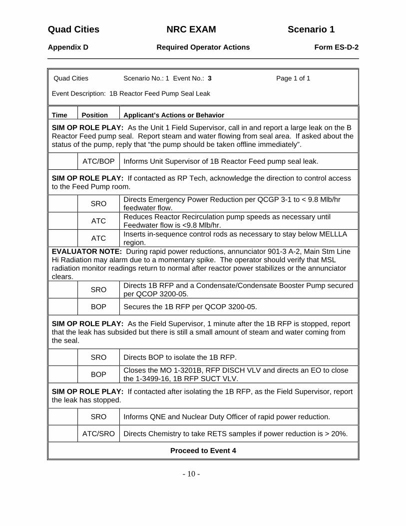
Quad Cities Scenario No.: 1 Event No.: 3 Page 1 of 1 Event Description: 1B Reactor Feed Pump Seal Leak
Time Position Applicant’s Actions or Behavior
SIM OP ROLE PLAY: As the Unit 1 Field Supervisor, call in and report a large leak on the B Reactor Feed pump seal. Report steam and water flowing from seal area. If asked about the status of the pump, reply that “the pump should be taken offline immediately”.
ATC/BOP Informs Unit Supervisor of 1B Reactor Feed pump seal leak.
SIM OP ROLE PLAY: If contacted as RP Tech, acknowledge the direction to control access to the Feed Pump room.
SRO Directs Emergency Power Reduction per QCGP 3-1 to < 9.8 Mlb/hr feedwater flow.
ATC Reduces Reactor Recirculation pump speeds as necessary until Feedwater flow is <9.8 Mlb/hr.
ATC Inserts in-sequence control rods as necessary to stay below MELLLA region.
EVALUATOR NOTE: During rapid power reductions, annunciator 901-3 A-2, Main Stm Line Hi Radiation may alarm due to a momentary spike. The operator should verify that MSL radiation monitor readings return to normal after reactor power stabilizes or the annunciator clears.
SRO Directs 1B RFP and a Condensate/Condensate Booster Pump secured per QCOP 3200-05.
BOP Secures the 1B RFP per QCOP 3200-05.
SIM OP ROLE PLAY: As the Field Supervisor, 1 minute after the 1B RFP is stopped, report that the leak has subsided but there is still a small amount of steam and water coming from the seal.
SRO Directs BOP to isolate the 1B RFP.
BOP Closes the MO 1-3201B, RFP DISCH VLV and directs an EO to close the 1-3499-16, 1B RFP SUCT VLV.
SIM OP ROLE PLAY: If contacted after isolating the 1B RFP, as the Field Supervisor, report the leak has stopped.
SRO Informs QNE and Nuclear Duty Officer of rapid power reduction.
ATC/SRO Directs Chemistry to take RETS samples if power reduction is > 20%.
Proceed to Event 4

Quad Cities NRC EXAM Scenario 1
- 11 -
Appendix D Required Operator Actions Form ES-D-2
Quad Cities Scenario No.: 1 Event No.: 4 Page 1 of 1 Event Description: Transformer 12 Oil Leak/Transfer Aux Power to Transformer 11
Time Position Applicant’s Actions or Behavior
SIM OP ROLE PLAY: As the outside EO, report a large oil leak on Transformer 12. All oil is contained in the burm.
SIM OP ROLE PLAY: If the crew pursues HAZMAT actions per QCOA 0010-15, then call in as Field Supervisor and report, “All oil is contained, and no HAZMAT exists. The HAZMAT Specialist will fill out all required reports.”
SRO Directs removal of Transformer 12 from service.
BOP Transfers aux power to Transformer 11 per QOP 6100-01 or deenergizes Transformer 12 by opening GCB 4-6 and GCB 3-4 and verifying Aux power transfers.
BOP Verifies Transformer 11 voltage and load are normal (in green band) and bus voltages are > 4000 KV after the XFMR 11 to Bus 12 ACB is closed.
BOP Verifies Transformer 11 voltage and load are normal (in green band) and bus voltages are > 4000 KV after XFMR 11 to Bus 13 ACB is closed.
BOP Verifies all 345 KV Bus section breakers are closed.
BOP Notifies BPO prior to opening 345 KV Bus CKT BKR 3-4 and CKT BKR 4-6.
SIM OP ROLE PLAY: As BPO, concur with opening of 345KV Bus CKT BKR 3-4 and 345 KV Bus CKT BKR 4-6.
BOP Opens 345 KV Bus CKT BKR 3-4 and 345 KV Bus CKT 4-6 at the 912-2 panel.
SRO Directs BOP to enter QCOA 6100-01, Loss of Reserve Auxiliary Transformer 12 (22) During Power Operation.
SRO Enters TS 3.8.1 Condition A, one required offsite circuit inoperable for Unit 1 and directs completion of QCOS 0005-08 within one hour and once per eight hours after.
Proceed to Event 5
Quad Cities NRC EXAM Scenario 1
- 12 -
Appendix D Required Operator Actions Form ES-D-2
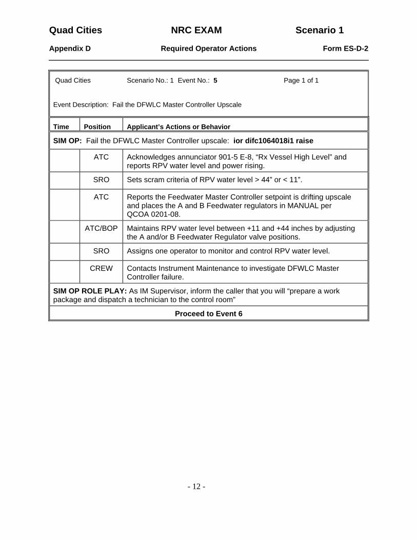
Quad Cities Scenario No.: 1 Event No.: 5 Page 1 of 1 Event Description: Fail the DFWLC Master Controller Upscale
Time Position Applicant’s Actions or Behavior
SIM OP: Fail the DFWLC Master Controller upscale: ior difc1064018i1 raise
ATC Acknowledges annunciator 901-5 E-8, “Rx Vessel High Level” and reports RPV water level and power rising.
SRO Sets scram criteria of RPV water level > 44” or < 11”.
ATC Reports the Feedwater Master Controller setpoint is drifting upscale and places the A and B Feedwater regulators in MANUAL per QCOA 0201-08.
ATC/BOP Maintains RPV water level between +11 and +44 inches by adjusting the A and/or B Feedwater Regulator valve positions.
SRO Assigns one operator to monitor and control RPV water level.
CREW Contacts Instrument Maintenance to investigate DFWLC Master Controller failure.
SIM OP ROLE PLAY: As IM Supervisor, inform the caller that you will “prepare a work package and dispatch a technician to the control room”
Proceed to Event 6

Quad Cities NRC EXAM Scenario 1
- 13 -
Appendix D Required Operator Actions Form ES-D-2
Quad Cities Scenario No.: 1 Event No.: 6 Page 1 of 1 Event Description: LOOP/LOCA (A Loop Reactor Recirc Pump Discharge Line Break)
Time Position Applicant’s Actions or Behavior
SIM OP NOTE: At the Lead Examiners direction, insert a .5% break ramped over 20 minutes on the A Loop Recirc pump discharge line: imf rr011a .5 20:
BOP Acknowledges annunciator 901-3 A-16, “PRI CNMT HIGH PRESSURE.”
SRO Sets scram criteria at 2.0 psig Drywell pressure and directs actions of QCOA 0201-01.
ATC/BOP Investigate cause of Drywell pressure rise by checking the following:
• Reactor Recirculation pump seals
• RBCCW system operation
• Safety/Relief valve leakage
• Drywell to Torus D/P controller operation.
ATC/BOP Notifies Radiation Protection of elevated Containment pressure and evacuates the Reactor Building.
BOP Starts all available Drywell Coolers and monitors leak rate.
SRO Briefs crew on methods of RPV water level, pressure control, and priorities with a loss of offsite power and a LOCA.
ATC Inserts a manual reactor scram when Drywell pressure reaches 2.0 psig.
SRO Enters QGA 100 on RPV low water level and QGA 200 when Drywell pressure reaches 2.5 psig (also re-enters QGA 100).
SRO Directs actions of QGA 100.
ATC Enters and executes actions of QCGP 2-3.
ATC/BOP Verifies isolations and auto actions for 0 inches RPV water level and 2.5 psig Drywell pressure.
Proceed to Event 7 & 8.

Quad Cities NRC EXAM Scenario 1
- 14 -
Appendix D Required Operator Actions Form ES-D-2
Quad Cities Scenario No.: 1 Event No.: 7 & 8 Page 1 of 1 Event Description: U-1 Emergency Diesel Generator Autostart Failure
HPCI Turbine trip
Time Position Applicant’s Actions or Behavior
BOP Reports the following failures: • HPCI Turbine trip • U-1 EDG failed to autostart
BOP Manually starts the U-1 EDG and verifies the B Loop Core Spray and RHR pumps autostart.
BOP Attempts to start HPCI per QCOP 2300-06 (Hard Card), and reports unable to start HPCI.
ATC/BOP Dispatches EO’s to investigate HPCI Turbine failure.
SIM OP ROLE PLAY: As EO dispatched to the HPCI Room, wait 2 minutes and report “you see no apparent cause for the HPCI turbine trip and will contact maintenance for assistance”. SRO Directs RPV water level maintained between 0 and 48 inches using
RCIC and Safe Shutdown Makeup Pump (SSMP). ATC/BOP Starts RCIC for injection per QCOP 1300-02. (Hard Card)
ATC/BOP Starts the SSMP for injection per QCOP 2900-02. (Hard Card)
SRO Verifies RPV pressure < 1060 psig and directs RPV cooldown using ADS valves.
BOP Starts cooldown at < 100°F/hr using the ADS valves, (action dependent on rate of depressurization).
SRO Directs restoration of Electric Plant as follows: • Re-energize RPS A and RPS B • Backfeed Bus 13 and Bus 14 • Restore 480V Bus 15, 16, and/or 17 as needed
ATC/BOP Dispatches EO to re-energize RPS A and RPS B per QOP 7000-01.
ATC/BOP Backfeeds Bus 13 and Bus 14 per QCOA 6100-03.
ATC/BOP Re-energizes Bus 15, 16, and/or Bus 17 per QCOA 6100-03.
SIM OP If requested wait 4 minutes and re-energize RPS A and RPS B from their normal power supplies:
RPS A: mrf rp02r mg_set mrf rp29r reset
RPS B: mrf rp03r mg_set mrf rp28r reset
Quad Cities NRC EXAM Scenario 1
- 15 -
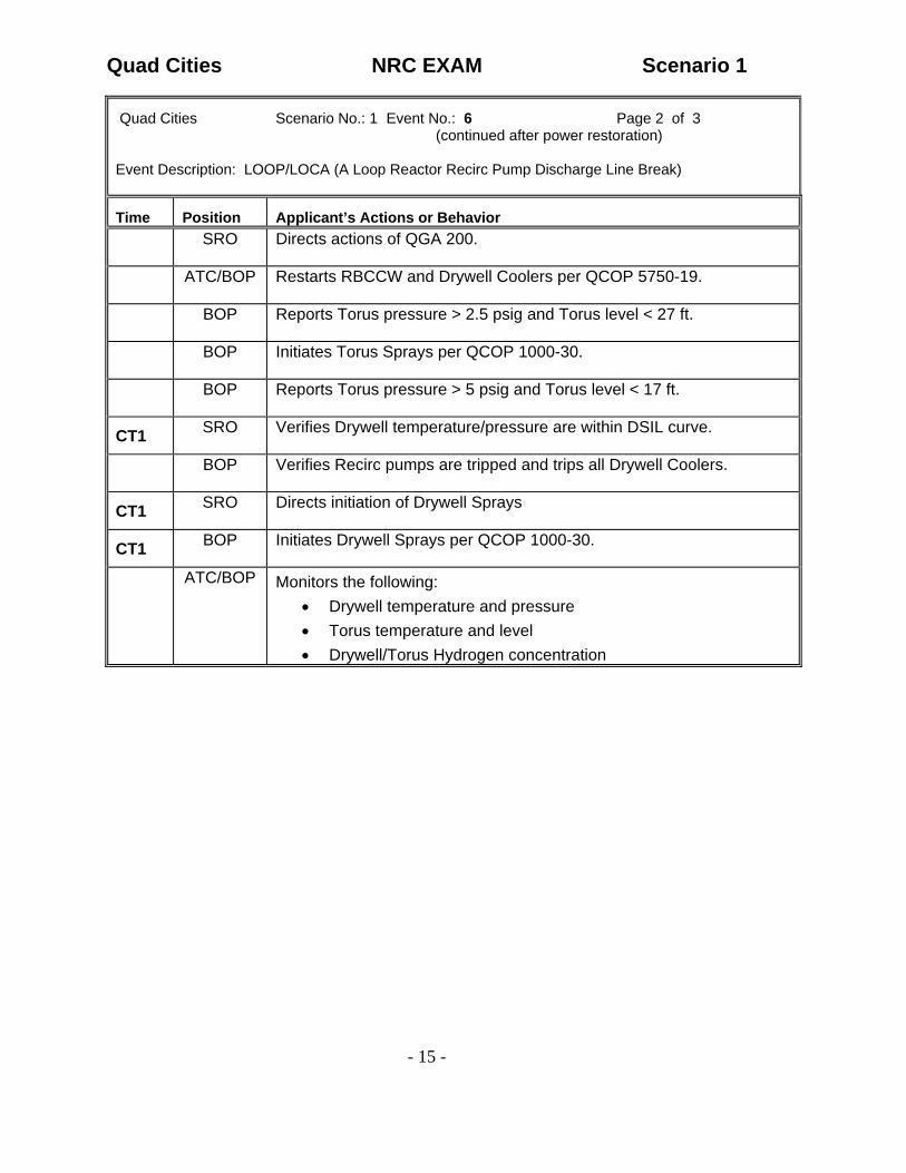
Quad Cities Scenario No.: 1 Event No.: 6 Page 2 of 3 (continued after power restoration)
Event Description: LOOP/LOCA (A Loop Reactor Recirc Pump Discharge Line Break)
Time Position Applicant’s Actions or Behavior
SRO Directs actions of QGA 200.
ATC/BOP Restarts RBCCW and Drywell Coolers per QCOP 5750-19.
BOP Reports Torus pressure > 2.5 psig and Torus level < 27 ft.
BOP Initiates Torus Sprays per QCOP 1000-30.
BOP Reports Torus pressure > 5 psig and Torus level < 17 ft.
CT1 SRO Verifies Drywell temperature/pressure are within DSIL curve.
BOP Verifies Recirc pumps are tripped and trips all Drywell Coolers.
CT1 SRO Directs initiation of Drywell Sprays
CT1 BOP Initiates Drywell Sprays per QCOP 1000-30.
ATC/BOP Monitors the following: • Drywell temperature and pressure • Torus temperature and level • Drywell/Torus Hydrogen concentration

Quad Cities NRC EXAM Scenario 1
- 16 -
Appendix D Required Operator Actions Form ES-D-2
Quad Cities Scenario No.: 1 Event No.: 6 Page 3 of 3 (continued after power restoration)
Event Description: LOOP/LOCA (A Loop Reactor Recirc Pump Discharge Line Break)
SRO Directs further actions of QGA 100 when RPV water level cannot be held above –59 inches.
CT2 SRO Directs BOP to inhibit ADS.
CT2 BOP Inhibits ADS.
SRO Directs use of Alternate Injection Systems.
ATC Injects SBLC per QCOP 1100-02.
ATC Starts a CRD pump if power is available or dispatches an EO to cross-tie the CRD system per QCOP 0300-19.
SIM OP ROLE PLAY: If Condensate crosstie is requested, state “the Unit 2 Condensate system is Out-of-Service.”
SRO Verifies 2 or more Detail F subsystems are available.
• SSMP
• B Core Spray
• B Loop RHR
ATC Reports RPV water level at –142 inches (TAF).
SRO Verifies injection sources are lined up with pumps running.

Quad Cities NRC EXAM Scenario 1
- 17 -
Quad Cities Scenario No.: 1 Event No.: 9 Page 1 of 1 Event Description: RPV Blowdown and Level Restoration
Time Position Applicant’s Actions or Behavior
SRO Enters QGA 500-1 before RPV water level drops to –166 inches and directs actions.
SRO Verifies all rods in and Drywell pressure at or above 2.5 psig.
BOP Reports Torus level > 5 ft.
CT3 SRO Directs BOP to open all 5 ADS valves and leave switches in Manual.
CT3 BOP Opens all 5 ADS valves and leaves switches in Manual.
ATC/BOP Monitor RPV depressurization and RPV water level.
BOP Verifies low pressure ECCS pumps inject when RPV pressure is < 325 psig.
CT4 SRO Directs RPV water level raised to above –142 inches.
CT4 ATC/BOP Restore RPV water level above –142” (TAF) by injecting with low pressure ECCS pumps.
End Of Scenario

Quad Cities NRC EXAM Scenario 2
- 1 -
Appendix D Scenario Outline Form ES-D-1
Facility: Quad Cities Scenario No.: NRC Scenario 2 Op-Test No.: ILT 08-1 _ Examiners: ____________________________ Operators: _____________________________
____________________________ _____________________________ ____________________________ _____________________________
Initial Conditions: 85 % power Turnover: Reverse Main Condenser Flow per QCOP 4400-09, then return to rated power by increasing core flow in accordance with QCGP 3-1 and the REMA.
Event No.
Malf. No. Event Type*
Event Description
1 None BOP N
Reverse Main Condenser flow
2 ED01C BOP IC
GCB 4-6 trip / reclose
3 RM05A SRO TS
DW Rad Mon fails upscale (TS)
4 FW08A ATC IC
FRV Lockup
5 HP13 BOP/SROIC
HPCI Steam leak / failure to isolate (TS)
6 MC08 ATC R
Main Condenser Vacuum leak / Emergency Power Reduction, ( attempt to maintain Main Condenser backpressure < 6.5 in Hg.)
7 RD13A Crew M
Manual Scram / ATWS (Hydraulic)
8 DIHS11130301 ATC IC
Malfunction after Major: Start failure of 1st SBLC Pump
9 MC08 Crew M
Complete Loss of Main Condenser Vacuum
10 None Crew M
Contingencies: Power Level Control QGA 101
* (N)ormal, (R)eactivity, (I)nstrument, (C)omponent, (M)ajor
ES-301-5 Quantitative attributes: BOP Normal: E1 ATC Reactivity (1 per set): E6 BOP I/C (4 per set): E2 & E5 ATC I/C (4 per set): E4 & E8 SRO-I I/C (4/set & 2 as ATC):E2, E4, E5, E8 SRO Tech Spec (2 per set): E3 & E5 ALL Major Transients (2 per set) E7
ES-301-4 Quantitative attributes: Total Malfunctions (5-8): 7 Malfunction(s) after EOP (1-2): E8 Abnormal Events (2-4): E2, E4, E5, E6 Major Transient(s) /E-Plan entry (1-2): E7 EOPs (1-2): 100 EOP Contingencies (0-2): 101 ATWS Critical Tasks (2-3): 5

Quad Cities NRC EXAM Scenario 2
- 2 -
SUMMARY: • The scenario starts with the crew holding power at approximately 85% with no LCOs in
effect. • The BOP operator reverses Main Condenser Circ Water flow. • GCB 4-6 is inadvertently tripped open during a Switchyard breaker inspection. The problem
is resolved and the US directs the BOP to reclose GCB 4-6 per QCOP 6400-08. • The Drywell Radiation Monitor fails upscale. The US must declare the monitor inoperable
and reference Technical Specifications. • The 1A Feedwater Reg Valve locks up. The ATC operator controls RPV water level and,
when the problem is resolved, resets the lock-up. • A steam leak begins in the HPCI room. The crew performs actions from QGA 300 and
manually isolates HPCI when the automatic isolation fails. • Main Condenser begins to degrade due to an air leak. The crew performs QOA 3300-02 and
Emergency Power Reduction. • The loss of vacuum results in a reactor scram, but control rods fail to fully insert due to a
hydraulic ATWS. The crew performs QGA 100 and QGA 101 in response. • When SBLC is initiated, the first pump selected will not start. The alternate pump will start if
a start is attempted. • A complete loss of Vacuum eliminates the Main Condenser as a heat sink. Operators must
manually control RPV Pressure with relief valves. Torus Cooling must be placed in service per QGA 200.
• The scenario is terminated when RPV water level and pressure are controlled in the established bands per QGA 101 and actions are being taken to shutdown the reactor.
CRITICAL TASKS: Critical Task #1: With a HPCI steam line break and a failure of the automatic isolation, take
action to manually isolate the HPCI steam line to terminate a primary system discharge into the Reactor Building.
Critical Task #2: With a reactor scram required and the reactor not shutdown, INHIBIT ADS to
prevent an uncontrolled RPV blowdown and significant power excursion. (BWR RPV-6.2 ATWS PWR/LVL INHIBIT ADS)
Critical Task #3: With a reactor scram required and the reactor not shutdown, TAKE ACTION
TO REDUCE POWER by injecting Boron (prior to exceeding 110°F Torus temperature) and/or inserting control rods to prevent exceeding primary containment design limits. (BWROG RPV-6.1 ATWS/PWR/LVL S/D REACTOR)
Critical Task #4: During an ATWS with conditions met to perform power/level control,
TERMINATE AND PREVENT INJECTION with the exception of Boron, CRD, and RCIC into the RPV until conditions are met to re-establish injection. ((BWROG RPV-6.3 PWR/LVL TERM/PREVENT)
Critical Task #5: When conditions are met to re-establish injection, use available injection
systems to MAINTAIN RPV water level above the Minimum Steam Cooling RPV Water Level ( -166”). (BWROG RPV-6.4 ATWS PWR/LVL RESTORE RPV LVL)

Quad Cities NRC EXAM Scenario 2
- 3 -
Simulator setup: 1. Reset to IC-23.
Verify Main Condenser flow is in the South direction.
2. Insert Commands for setup: • imf hp15 • imf rd13a 100 • ior dihs11130301 off • irf mc20br open • irf mc20ar open
3. Verify the flowing commands for scenario performance:
• imf ed01c • dmf ed01c • imf rm05a 100 :10 • imf fw08a • dmf fw08a • imf hp13 7 2: • irf sw10r run • imf mc08 100 25: • irf rd04r close • irf qg08r 1 • irf qg14r 1 • irf qg09r 1 • dor dihs11130301
4. Take the following equipment OOS (hang OOS Card):
• None. 5. Provide the crew with a Standard Load Drop REMA. 6. Provide the Lead Evaluator with Switching Orders to reclose GCB 4-6. 7. Need to have blank EST available for use during the scenario.
None
8. Ensure procedures are erased and put away including QGAs. 9. Advance recorders. 10. Clean marked up meter/recorder faces and hard cards. 11. Remove any flags placed by the previous crew.

Quad Cities NRC EXAM Scenario 2
- 4 -
LIST OF POTENTIAL PROCEDURES
− Annunciator Procedures
o 901-5 A-8, Rev. 14 o 901-55 A-1, Rev. 10 o 901-5 G-7, Rev. 6 o 901-4 G-17, Rev. 10
− QGA 100, Rev. 9
− QGA 101, Rev. 13
− QGA 200, Rev. 9
− QCOA 0600-01, Rev. 11
− QOA 3300-02, Rev. 34
− QCOP 6400-08, Rev. 14
− QCOP 4400-09, Rev. 20
− QCOP 0300-28, Rev. 27
− QCOP 0250-02, Rev. 11
− QCOP 0201-16, Rev. 5
− QCOP 0600-18, Rev. 20
− QCOP 2400-01, Rev. 18
− QCOP 1000-30, Rev. 23

Quad Cities NRC EXAM Scenario 2
- 5 -
CREW TURNOVER SHIFT TURNOVER INFORMATION
1. Plant Conditions:
a.) Unit 1 is operating at 85% power. b.) Unit 2 is at rated power
c.) Technical Specification limitations:
(1) Unit 1: None (2) Unit 2: None
d.) On Line Risk is Green
. 2.) Evolutions/maintenance for the oncoming shift:
a.) Reverse Main Condenser Flow per QCOP 4400-09. b.) Increase to rated power with Recirc flow per QCGP 3-1, Reactor Power
Operation.

Quad Cities NRC EXAM Scenario 2
- 6 -
Appendix D Required Operator Actions Form ES-D-2
Quad Cities Scenario No.: 2 Event No.: 1 Page 1 of 1 NOTE: Event Description: Reverse Main Condenser Flow from South to North
Time Position Applicant’s Actions or Behavior
SRO Directs Main Condenser flow reversal per QCOP 4400-09.
BOP Verifies annunciator 901-7 C-1, “COND FLOW REV VLVS ON LOCAL CONT,” is NOT in alarm.
BOP Opens South SJAE Suction valves using the Test switch on the 901-7 panel by placing the switch to the “SOU” position.
BOP Places the Circulating Water Flow Selector switch to the “NORTH” position when the South SJAE valves are fully open.
BOP Verifies the following:
• SJAE Suction valves change over
• Condenser seal trough fill and drain valves changeover
• Condenser differential pressure has reversed and vacuum is stable
BOP Verifies after a time delay that one set of seal troughs have drained and the other has filled.
Proceed to Event 2

Quad Cities NRC EXAM Scenario 2
- 7 -
Appendix D Required Operator Actions Form ES-D-2
Quad Cities Scenario No.: 2 Event No.: 2 Page 1 of 1 Event Description: GCB 4-6 Trip and Reclosure
Time Position Applicant’s Actions or Behavior
SIMOP: Trip GCB 4-6 using the command imf ed01c, then delete the GCB 4-6 trip to allow re-close using dmf ed01c
BOP Acknowledges annunciator 912-2 C-3, “345KV CKT BKR TRIP,” and reports GCB 4-6 has tripped.
BOP Refers to annunciator procedure and dispatches an EO to the Relay House.
SIM OP ROLE PLAY: As OAD, call into the Control Room and report you inadvertently bumped the control cabinet for GCB 4-6 while staging equipment for an upcoming modification. You have inspected the cabinet and found no damage. You suggest contacting Transmission and reclosing GCB 4-6.
LEAD EVALUATOR NOTE: Provide a copy of the Switching Orders after the SRO requests them from Transmission.
SRO Contacts Transmission Operations for permission and Switching Orders to reclose GCB 4-6.
SRO Directs reclosure of GCB 4-6 per QCOP 6400-08.
BOP Directs EO in the Relay House to inspect GCB 4-6 and surrounding area prior to closure of the circuit breaker.
SIM OP ROLE PLAY: As EO, call back after approximately 2 minutes, and report area is cleared of all personnel and no safety hazards exist. If directed or asked to complete QCOP 6400-08 steps F.2a.-c., wait 1 minute and report those steps as complete.
BOP
Turns on the 345KV Synchronization Switch with the key and verifies synchroscope is at 12 o’clock and incoming and running voltages are equal.
BOP Closes GCB 4-6 with the control switch at the 912-2 panel and verifies both RED lights are energized.
BOP Turns off 345KV breaker synchronization switch and removes key.
BOP Verifies re-closure cutout toggle switch is in the UP (ON) position.
Proceed to Event 3

Quad Cities NRC EXAM Scenario 2
- 8 -
Appendix D Required Operator Actions Form ES-D-2
Quad Cities Scenario No.: 2 Event No.: 3 Page 1 of 1 Event Description: 1A Drywell Radiation Monitor Upscale Failure
Time Position Applicant’s Actions or Behavior
SIMOP: Fail the 1A Drywell Radiation Monitor Upscale: imf rm05a 100 :10
BOP Acknowledges annunciator 901-55 A-1, “Drywell A High Rad Conc,” and reports the 1-2419A Drywell radiation monitor is indicating full upscale.
ATC Acknowledges annunciator 901-5 A-8, “Group 2 Isol Ch Trip,” and refers to annunciator procedure.
SRO Confirms the 1-2419B Drywell radiation monitor is indicating normally (approximately 3-4 R/hr), and no other indications of increasing radiation levels exist on the following:
• Main Steam Line Radiation monitors
• Offgas Radiation monitors
• Area Radiation monitors
SRO Enters the following Technical Specifications for an inoperable Drywell Radiation monitor:
• PCI 3.3.6.1, Condition A, Place the Channel in Trip Within 24 Hours
• PAM 3.3.3.1, Condition A, Restore Required Channel to Operable Status Within 30 Days
Proceed to Event 4

Quad Cities NRC EXAM Scenario 2
- 9 -
Appendix D Required Operator Actions Form ES-D-2
Quad Cities Scenario No.: 2 Event No.: 4 Page 1 of 1 Event Description: 1A Feedwater Regulator Valve Lock-Up
Time Position Applicant’s Actions or Behavior
SIM OP: Lock-up the 1A FRV using the command: imf fw08a
ATC Acknowledges annunciator 901-5 G-7, “1A FW ACTUATOR TROUBLE,” and reports the 1A FRV has locked up.
ATC Verifies and reports that the 1B FRV is in AUTO and controlling RPV water level.
SRO/ATC Contacts Instrument Maintenance to investigate the 1A FRV lock-up and dispatches EO to the Feedwater Regulator Station to investigate.
BOP Checks Fuse F13 at Panel 901-5 TB-HH and reports the fuse is intact.
EVALUATOR NOTE: The above mentioned fuse is not modeled. When the candidate is at the 901-5 inside panel, inform him/her that “the fuse is intact”.
SIM OP ROLE PLAY: As EO dispatched to the 1A Feed Reg Valve, report that the Nematron is displaying an “Input Signal vs Valve Position Error”.
SIM OP ROLE PLAY: As Instrument Maintenance, wait 3 minutes, delete the lock-up malfunction by inserting the command: dmf fw08a. Call back and report you have corrected the control signal problem by cleaning and securing several leads. You recommend resetting the lock-up.
SRO Directs resetting the 1A FW Regulator valve per QCOA 0600-01 and QCOP 0600-18, step F.4.
ATC Verifies the 1B FRV is controlling RPV water level.
ATC Depresses the 1A VLV RESET pushbutton and holds for five seconds.
ATC Verifies the 1A FRV lock-up reset light extinguishes and the valve is controlling RPV water level.
ATC Places 1A FRV in AUTO per QCOP 0600-18 step F.5
Proceed to Event 5
Quad Cities NRC EXAM Scenario 2
- 10 -
Appendix D Required Operator Actions Form ES-D-2
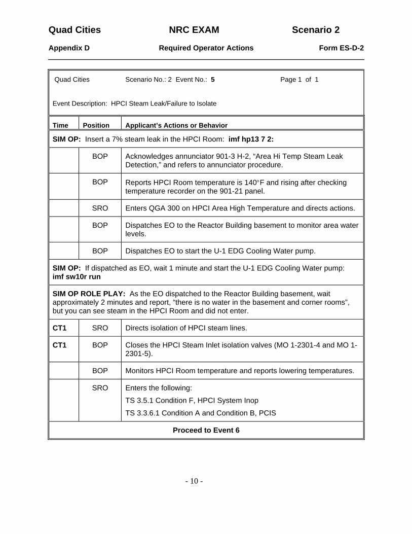
Quad Cities Scenario No.: 2 Event No.: 5 Page 1 of 1 Event Description: HPCI Steam Leak/Failure to Isolate
Time Position Applicant’s Actions or Behavior
SIM OP: Insert a 7% steam leak in the HPCI Room: imf hp13 7 2:
BOP Acknowledges annunciator 901-3 H-2, “Area Hi Temp Steam Leak Detection,” and refers to annunciator procedure.
BOP Reports HPCI Room temperature is 140°F and rising after checking temperature recorder on the 901-21 panel.
SRO Enters QGA 300 on HPCI Area High Temperature and directs actions.
BOP Dispatches EO to the Reactor Building basement to monitor area water levels.
BOP Dispatches EO to start the U-1 EDG Cooling Water pump.
SIM OP: If dispatched as EO, wait 1 minute and start the U-1 EDG Cooling Water pump: imf sw10r run
SIM OP ROLE PLAY: As the EO dispatched to the Reactor Building basement, wait approximately 2 minutes and report, “there is no water in the basement and corner rooms”, but you can see steam in the HPCI Room and did not enter.
CT1 SRO Directs isolation of HPCI steam lines.
CT1 BOP Closes the HPCI Steam Inlet isolation valves (MO 1-2301-4 and MO 1-2301-5).
BOP Monitors HPCI Room temperature and reports lowering temperatures.
SRO Enters the following:
TS 3.5.1 Condition F, HPCI System Inop
TS 3.3.6.1 Condition A and Condition B, PCIS
Proceed to Event 6

Quad Cities NRC EXAM Scenario 2
- 11 -
Appendix D Required Operator Actions Form ES-D-2
Quad Cities Scenario No.: 2 Event No.: 6 Page 1 of 1 Event Description: Main Condenser Vacuum Leak/Emergency Power Reduction/Scram
Time Position Applicant’s Actions or Behavior
SIM OP: Insert a 100% Main Condenser leak ramped over 25 minutes: imf mc08 100 25:
BOP Acknowledges annunciator 901-3 D-2, “Off Gas High Radiation,” and confirms elevated Off-Gas radiation levels at the 901-10 panel.
EVALUATOR NOTE: The Off-Gas radiation monitor readings will increase with an elevated flow rate resulting from air in-leakage. It is not indicative of fuel damage in this case.
BOP Acknowledges annunciator 901-54 C-7, “Normal Process Flow Hi/Lo,” and reports off-gas flow > 100 scfm and Main Condenser backpressure rising.
SRO Enters QOA 3300-02, Loss of Vacuum, and orders Emergency Power Reduction to maintain < 5 inches/Hg backpressure in Main Condenser.
ATC/BOP Reduces Reactor Recirculation flow and inserts control rods as necessary to attempt to maintain Main Condenser backpressure < 5 in Hg.
SRO Sets scram criteria of 6.5 in./Hg Main Condenser backpressure.
ATC/BOP Checks SJAE valve position, steam seal pressure, and dispatches EO’s and Radiation Protection to look for leaks in the LP Heater Bay.
ATC/BOP Dispatches EOs to fill loop seals per QCOP 3300-09 and verify the Main Condenser vacuum breaker is closed and has a water seal.
ATC Scrams the reactor on high Main Condenser backpressure by depressing both manual scram pushbuttons and places the mode switch to the “SHUTDOWN” position.
Proceed to Event 7

Quad Cities NRC EXAM Scenario 2
- 12 -
Appendix D Required Operator Actions Form ES-D-2
Quad Cities Scenario No.: 2 Event No.: 7 Page 1 of 2 Event Description: Hydraulic ATWS
Time Position Applicant’s Actions or Behavior
ATC Reports control rods did NOT insert.
SRO Enters QGA 100, transitions to QGA 101.
SRO Directs actions for Power Leg of QGA 101.
ATC Arms and depresses ARI, and reduces both Reactor Recirc pumps to minimum speed.
CT2 SRO Directs ATC/BOP to inhibit ADS
CT2 BOP Inhibits ADS and places both Core Spray pumps in PTL.
SRO Directs both Reactor Recirc pumps tripped.
ATC Trips both Reactor Recirc pumps.
CT3 SRO Directs control rod insertion per QCOP 0300-28.
ATC Dispatches EO to close the 1-301-25 valve.
CT3 ATC Inserts all CRAM rods to position 00.
CT3 ATC Continues to insert control rods spiraling outward from center of core.
ATC Directs operator to bypass all reactor scrams per QCOP 0300-28.
ATC Resets reactor scram.
ATC Dispatches EO to de-energize ARI by removing fuses in 2201-70A and 2201-70B panels per QCOP 0300-28.
ATC Verifies scram is reset and inserts another manual scram.
ATC Verifies NO control rod movement and resets reactor scram.

Quad Cities NRC EXAM Scenario 2
- 13 -
Appendix D Required Operator Actions Form ES-D-2
Quad Cities Scenario No.: 2 Event No.: 7 Page 2 of 2 Event Description: Hydraulic ATWS
Time Position Applicant’s Actions or Behavior
ATC Directs personnel to individually scram control rods from the 901-16 panel.
SIM OP ROLE PLAY: Attempt to individually scram 3 control rods, then contact the ATC operator and report, “Control rods will not insert from the 901-16 panel.”
SIM OP ROLE PLAY: If requested as EO, closes the 1-301-25 valve using: irf rd04r close
SIM OP ROLE PLAY: If requested, wait approx. 2 minutes and bypass all reactor scrams using: irf qg08r 1
SIM OP ROLE PLAY: If requested as EO, pull the ARI fuses in the 2201-70A and 2201-70B panels in Aux Electric Room using: irf qg14r 1
SIM OP ROLE PLAY: If requested, bypass the Low RPV water level MSIV isolation and High Radiation Offgas isolation per QCOP 0250-02 using: irf qg09r 1
Proceed to Event 8

Quad Cities NRC EXAM Scenario 2
- 14 -
Appendix D Required Operator Actions Form ES-D-2
Quad Cities Scenario No.: 2 Event No.: 8 Page 1 of 1 Event Description: Failure of Initial SBLC Pump to Inject
Time Position Applicant’s Actions or Behavior
SIM OP NOTE: Delete the override for the SBLC switch when the ATC operator selects the 2nd SBLC pump for injection. dor dihs11130301
ATC Reports SBLC tank level and selects a SBLC pump for injection by placing the control switch to SYS 1 or SYS 2.
CT3 ATC Reports the SBLC pump has failed to inject, and selects the other SBLC pump.
ATC Verifies and reports the 2nd SBLC pump is injecting.
ATC Monitors SBLC Tank level for 16% decrease.
Proceed to Event 9
Quad Cities NRC EXAM Scenario 2
- 15 -
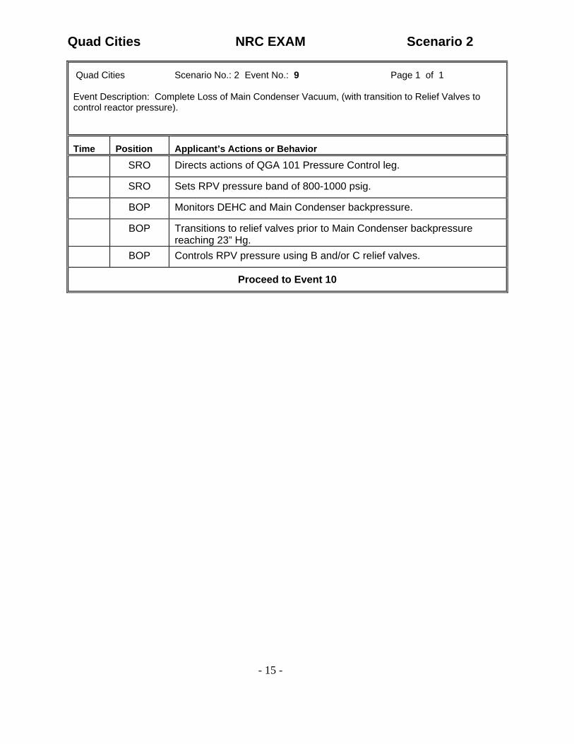
Quad Cities Scenario No.: 2 Event No.: 9 Page 1 of 1 Event Description: Complete Loss of Main Condenser Vacuum, (with transition to Relief Valves to control reactor pressure).
Time Position Applicant’s Actions or Behavior
SRO Directs actions of QGA 101 Pressure Control leg.
SRO Sets RPV pressure band of 800-1000 psig.
BOP Monitors DEHC and Main Condenser backpressure.
BOP Transitions to relief valves prior to Main Condenser backpressure reaching 23” Hg.
BOP Controls RPV pressure using B and/or C relief valves.
Proceed to Event 10

Quad Cities NRC EXAM Scenario 2
- 16 -
Appendix D Required Operator Actions Form ES-D-2
Quad Cities Scenario No.: 2 Event No.: 10 Page 1 of 2 Event Description: RPV Power, Level Control
Time Position Applicant’s Actions or Behavior
SRO Directs actions of QGA 101 Level Control Leg.
BOP Verifies auto actions and isolations for 0 inches RPV water level.
SRO Directs isolations bypassed per QCOP 0250-02.
BOP Contacts EO/SS to bypass RPV low water level MSIV and high offgas radiation isolations per QCOP 0250-02.
SIM OP: If requested, bypass isolations per QCOP 0250-02: irf qg09r 1 SRO Verifies reactor power >5% and RPV water level > -35”.
CT4 SRO Directs termination and prevention of all RPV injection except for Boron and CRD.
CT4 ATC Isolates Condensate/Feed system per QCOP 0201-16 (Hard Card).
CT4 ATC/BOP Trip latches HPCI, and verifies no injection sources except for Boron and CRD are operating.
ATC/BOP Monitors RPV water level and reactor power.
ATC/BOP Reports RPV water level at –35 inches and lowering.
SRO Sets RPV water level band between –166 inches and the level lowered to when reactor power indicates < 5% or RPV water level is -142”, or all ADS valves stay closed and drywell pressure stays below 2.5 psig.
CT5 SRO Directs injection with Condensate/Feed system to maintain RPV water level in established band.
CT5 ATC/BOP Re-establishes injection to control RPV water level in band using the Condensate/Feed system.

Quad Cities NRC EXAM Scenario 2
- 17 -
Appendix D Required Operator Actions Form ES-D-2
Quad Cities Scenario No.: 2 Event No.: 10 Page 2 of 2 Event Description: QGA 200 Actions
Time Position Applicant’s Actions or Behavior
BOP Acknowledges annunciator 901-4 G-17, “Torus Wtr High Temp” and reports Torus temperature is 90°F and rising.
SRO Directs actions of QGA 200.
BOP Monitors and reports containment parameters.
BOP Starts the CAM system per QCOP 2400-01.
SRO Directs Torus Cooling initiated.
BOP Starts Torus Cooling per QCOP 1000-30 (Hard Card).
End of Scenario
Quad Cities NRC EXAM Scenario 3
- 1 -
Appendix D Scenario Outline Form ES-D-1
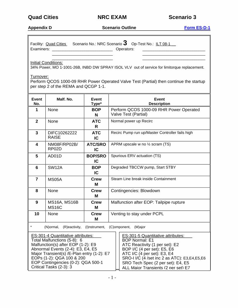
Facility: Quad Cities Scenario No.: NRC Scenario 3 Op-Test No.: ILT 08-1 __ Examiners: ____________________________ Operators: _____________________________
____________________________ _____________________________ ____________________________ _____________________________
Initial Conditions: 34% Power, MO 1-1001-26B, INBD DW SPRAY ISOL VLV out of service for limitorque replacement. Turnover: Perform QCOS 1000-09 RHR Power Operated Valve Test (Partial) then continue the startup per step 2 of the REMA and QCGP 1-1.
Event No.
Malf. No. Event Type*
Event Description
1 None BOP N
Perform QCOS 1000-09 RHR Power Operated Valve Test (Partial)
2 None ATC R
Normal power up Recirc
3 DIFC10262222 RAISE
ATC IC
Recirc Pump run up/Master Controller fails high
4 NM08F/RP02B/ RP02D
ATC/SRO IC
APRM upscale w no ½ scram (TS)
5 AD01D BOP/SROIC
Spurious ERV actuation (TS)
6 SW12A BOP IC
Degraded TBCCW pump, Start STBY
7 MS05A Crew M
Steam Line break inside Containment
8 None Crew M
Contingencies: Blowdown
9 MS16A, MS16B MS16C
Crew M
Malfunction after EOP: Tailpipe rupture
10 None Crew M
Venting to stay under PCPL
* (N)ormal, (R)eactivity, (I)nstrument, (C)omponent, (M)ajor
ES-301-5 Quantitative attributes: BOP Normal: E1 ATC Reactivity (1 per set): E2 BOP I/C (4 per set): E5, E6 ATC I/C (4 per set): E3, E4 SRO-I I/C (4 /set inc 2 as ATC): E3,E4,E5,E6 SRO Tech Spec (2 per set): E4, E5 ALL Major Transients (2 per set) E7
ES-301-4 Quantitative attributes: Total Malfunctions (5-8): 6 Malfunction(s) after EOP (1-2): E9 Abnormal Events (2-4): E3, E4, E5 Major Transient(s) /E-Plan entry (1-2): E7 EOPs (1-2): QGA 100 & 200 EOP Contingencies (0-2): QGA 500-1 Critical Tasks (2-3): 3

Quad Cities NRC EXAM Scenario 3
- 2 -
SUMMARY: • The scenario starts with the plant at approximately 34% power during a startup. The B Loop
of Drywell Sprays is inoperable. • Before power ascension, perform the RHR Power Operated Valve Test, QCOS 1000-09
step H.14 only. • The crew then raises reactor power by increasing Recirc Flow. • When the reactivity manipulation has been sufficiently evaluated, the Master Recirc
Controller will fail high. APRM power, Total Core Flow, and Recirc Pump speeds will all show increasing trends. There are several ways for the ATC operator to take manual control and terminate the transient.
• APRM 6 will fail upscale but a ½ scram will fail to occur. The crew should diagnose this problem and insert a manual ½ Scram. APRM 6 will be inoperable per Tech Specs.
• The D Relief Valve will actuate. The crew responds per QCOA 0203-01 to close the valve and stabilize the plant. One ADS valve will be inoperable per Tech Specs.
• The 1A TBCCW Pump will degrade. The B TBCCW Pump can be manually started and the system stabilized .
• A steam line break inside the Drywell results in a reactor scram and entry into QGA 100 and 200.
• When the only available loop of Drywell Sprays cannot be placed in service, the crew will perform a RPV Blowdown per QGA 500-1.
• When relief valves are opened, tailpipe ruptures pressurize the containment even further. • The crew must perform Containment Venting to stay under the Primary Containment
Pressure Limit (PCPL). CRITICAL TASKS: Critical Task #1: Given an operating plant with a stuck open relief valve, take actions to close
the valve in accordance with QCOA 0203-01. Critical Task #2: When Drywell temperature CANNOT be maintained < 280°F OR Torus
pressure CANNOT be maintained < Pressure Suppression Pressure Limit (PSP), INITIATE an Emergency Depressurization.
Critical Task #3: Before Torus pressure reaches the Primary Containment Pressure Limit (PCPL), INITIATE venting of the containment irrespective of offsite radioactivity release rates. (BWROG PC-7.2 LOCA VENT PC VENT)

Quad Cities NRC EXAM Scenario 3
- 3 -
Simulator setup: 1. Reset to IC-17.
• Verify RWM loads to proper sequence (if not, repeat IC-17 reset). • Withdraw Step 19 to the target out position. • Place DFWLC system in 3-element control. • Increase Reactor Recirc flow until Feedwater flow is 3.0 Mlb/hr. • Verify Recirc Controllers are in MASTER • Place DFWLC system in 3-element control. • Close Feedwater Heater Extraction and Vent Valves (QCGP 1-1 step F.9.k and F.9.l ) • Place the ADSORB INLT/BYP VLVS switch to the TREAT position (901-54)
(Commands to be utilized DURING the scenario are contained in the CAEP file NRC Scenario #3 2. Run CAEP file and verify the following setup commands are inserted:
• trgset 1 “zdifc1026222(1)” • trg 1 “dor difc10262222” • ior dihs1100123a close • imf rp02b • imf rp02d • irf rh20br open • irf rh19br open • trgset 3 “rdv10305117.LT.0.99” • imf rp05a(3) • imf rp05b(3 1) • imf rp05c(3 2) • trgset 4 “zdihs10287303A(1)” • imf ms16a(4) • imf ms16b(4) • imf ms16c(4) • irf ms01r latch • irf ms02r latch • irf ms03r latch • irf ms04r latch • irf ms05r latch • irf ms06r latch
3. Verify the flowing commands for scenario performance are available in the CAEP file:
• ior difc10262222 raise • imf nm08f 100 • imf ad01d 0 • imf sw12a 100 10: • imf ms05a .3 3: • irf rh19ar open
4. Take the following equipment OOS (hang OOS Card/EST): • APRM 5 in Bypass/EST • MO 1-1001-26B Control Switch OOS • MO 1-1001-23B Control Switch OOS

Quad Cities NRC EXAM Scenario 3
- 4 -
5. Provide the crew with a startup REMA. 6. Provide a current revision of the following procedures, signed off as specified:
• QCOS 1000-09, partial for Step #14, RHR B Containment Cooling Valves and IST data attached.
• QCGP 1-1, signed off up to F.9.v • Stopwatch
7 Ensure procedures are erased and put away including QGAs. 8. Advance recorders. 9. Clean marked up meter/recorder faces and hard cards. 10. Remove any flags placed by the previous crew.

Quad Cities NRC EXAM Scenario 3
- 5 -
LIST OF POTENTIAL PROCEDURES
− Annunciator Procedures o 901-3 A-16, Rev. 11 o 901-5 D-13, Rev. 9 o 901-5 A-6, Rev. 8 o 901-5 C-3, Rev. 11 o 901-5 H-1, Rev. 3 o 901-5 B-11, Rev. 10 o 901-3 E-13, Rev. 5 o 901-3 E-14, Rev. 7
− QCGP 1-1, Rev. 78
− QCGP 2-3, Rev. 66
− QGA 100, Rev. 9
− QGA 200, Rev. 9
− QGA 500-1, Rev. 13
− QCOA 0201-01, Rev. 22
− QCOA 0700-03, Rev. 8
− QCOA 0202-02, Rev. 13
− QCOA 0203-01, Rev. 12
− QCOA 0400-01, Rev. 20
− QCOP 0202-03, Rev. 18
− QCOP 1600-13, Rev. 22
− QCOS 1000-09, Rev. 19

Quad Cities NRC EXAM Scenario 3
- 6 -
SHIFT TURNOVER INFORMATION
1. Plant Conditions:
a.) Unit 1 is at approximately 34% power starting up from a weekend outage. b.) Unit 2 is at rated power.
c.) Technical Specification limitations:
(1) Unit 1:
TS 3.6.1.3, Condition A, for the MO 1-1001-26B PCI Valve inoperable. Day 1/7, TLCO 3.6.a, Condition A, One Drywell Spray Subsystem Inoperable
(2) Unit 2: None
d.) On Line Risk is Green
. 2.) Significant problems/abnormalities:
a.) The MO 1-1001-26B, INBD DW SPRAY ISOL VLV, is Out-Of-Service for a limitorque replacement after the valve failed to stroke during performance of QCOS 1000-09.
b.) APRM 5 is bypassed due to erratic indications. Instrument Maintenance is
preparing a troubleshooting package.
3.) Evolutions/maintenance for the oncoming shift:
a.) Complete QCOS 1000-09, RHR Power Operated Valve Test, step 14 only. (Partial for RHR B Containment Cooling Valves)
. b.) Continue the start-up per the REMA and QCGP 1-1, step F.9.v.

Quad Cities NRC EXAM Scenario 3
- 7 -
Appendix D Required Operator Actions Form ES-D-2
Quad Cities Scenario No.: 3 Event No.: 1 Page 1 of 1 NOTE: Event Description: QCOS 1000-09, RHR Power Operated Valve Test for the B Loop Containment Cooling Valves ONLY.
Time Position Applicant’s Actions or Behavior
SRO Authorizes performance of QCOS 1000-09, RHR Power Operated Valve Test, Step 14 for the RHR B Loop Containment Cooling Valves.
BOP Opens and times the MO 1-1001-36B, Torus Test or Spray Valve.
BOP Records time and verifies opening time meets IST criteria.
BOP Closes and times the MO 1-1001-36B valve.
BOP Records time and verifies closing time meets IST criteria.
BOP Opens and times the MO 1-1001-37B, Torus Spray Shutoff Valve.
BOP Records time and verifies opening time meets IST criteria.
BOP Closes and times the MO 1-1001-37B valve.
BOP Records time and verifies closing time meets IST criteria.
BOP Opens and times the MO 1-1001-34B, Torus Test or Spray Valve.
BOP Records time and verifies opening time meets IST criteria
BOP Closes and times the MO 1-1001-34B valve
BOP Records time and verifies closing time meets IST criteria.
BOP Returns the surveillance to the Unit Supervisor for independent verification of the B Loop Containment Cooling Valves.
Proceed to Event 2

Quad Cities NRC EXAM Scenario 3
- 8 -
Appendix D Required Operator Actions Form ES-D-2
Quad Cities Scenario No.: 3 Event No.: 2 Page 1 of 1 Event Description: Normal Power Increase with Reactor Recirculation Pumps
Time Position Applicant’s Actions or Behavior
SRO Directs Reactor power increase per REMA and QCGP 1-1.
ATC Raises Recirculation flow by depressing the RAISE pushbutton on the 1-0262-22, MASTER SPEED DEMAND CONTROLLER.
ATC Monitors Recirculation pump speeds, Total Core Flow, APRM power, RPV water level, and RPV pressure.
BOP Peer checks operation of the 1-0262-22, Master Controller.
ATC Refers to QCGP 3-1 when reactor power is greater than 35%.
ATC/BOP Adjusts Load Set to approximately 10% above Main Generator Load per QCGP 3-1 Attachment D.
ATC Verifies annunciator 901-5 H-4 resets when reactor power is > 38.5%.
ATC Monitors Condensate Demin differential pressure (<30 psid) and Condensate Demin flows (<3000 gpm). Places additional Demineralizers in service as necessary.
SIM OP ROLE PLAY: If requested as EO place additional Demineralizers in service using the commands irf fw02r through fw08r.
NOTE: After the required power change has been completed, proceed to Event 3.

Quad Cities NRC EXAM Scenario 3
- 9 -
Appendix D Required Operator Actions Form ES-D-2
Quad Cities Scenario No.: 3 Event No.: 3 Page 1 of 1 Event Description: Reactor Recirculation Pump Master Controller Fails High
Time Position Applicant’s Actions or Behavior
SIMOP: At the evaluator’s instruction, fail the Reactor Recirculation Master Controller RAISE pushbutton with the following command: ior difc10262222 raise
ATC Reports APRM power, total core flow, and Reactor Recirculation pump speeds increasing.
SRO Directs actions of QCOA 0202-02 and QCOP 0202-03.
ATC Performs one of the following to terminate the power increase:
• Place the 1-0262-25A and 1-262-25B Loop A/B SPEED CONTROLLERS in individual Manual mode.
• Depress the LOWER pushbutton on the 1-0262-22 Master Speed Demand Controller.
• Lock-up both Recirc MG sets by placing the Scoop Tube Power Reset switches to the “LOCKUP” position.
ATC Contacts Instrument Maintenance to investigate cause of the Master Controller failure.
ATC/BOP Adjusts Load Set if necessary
SRO Directs actions of QCOA 0400-01, Reactivity Addition.
ATC Monitors LRPM/APRM levels and SRM period indications for signs off core instabilities.
ATC/BOP Verify Flow Control Line is < 100%.
SIM OP ROLE PLAY: If contacted as QNE acknowledge the report of the Master Controller failure and state you will verify compliance with thermal limits.
Proceed to Event 4

Quad Cities NRC EXAM Scenario 3
- 10 -
Appendix D Required Operator Actions Form ES-D-2
Quad Cities Scenario No.: 3 Event No.: 4 Page 1 of 1 Event Description: APRM 6 Upscale With No ½ Scram
Time Position Applicant’s Actions or Behavior
SIM OP: Fail APRM 6 upscale HI-HI: imf nm08f 100
ATC Acknowledges annunciator 901-5 D-13, “APRM HI-HI OR INOP” and reports APRM 6 indicates HI-HI and RPS B failed to scram.
ATC Manually inserts a ½ scram in RPS B.
SRO Refers to QCOA 0700-03 and directs crew to hold Reactor power constant.
BOP Verifies APRM 6 indicates HI-HI in the 901-37 panel.
ATC Refers to the following annunciator procedures and reports to the Unit Supervisor that all are expected for the condition:
• 901-5 A-6, APRM Upscale High • 901-5 C-3, Rod Out Block • 901-5 H-1, OPRM Trouble/Inop • 901-5 B-11, Channel A/B Neutron Monitor
ATC/BOP Contacts Instrument Maintenance to troubleshoot APRM 6.
SRO Enters TS 3.3.1.1 Condition A, APRM inoperable. Verifies minimum number of APRM’s (4) per TRM 3.3.a are operable.
Proceed to Event 5

Quad Cities NRC EXAM Scenario 3
- 11 -
Appendix D Required Operator Actions Form ES-D-2
Quad Cities Scenario No.: 3 Event No.: 5 Page 1 of 1 Event Description: Spurious ERV Actuation
Time Position Applicant’s Actions or Behavior
SIM OP: Fail the 1-203-3D Relief Valve open: imf ad01d 0
BOP Acknowledges annunciator 901-3 E-13, “Elect Relief Valves 3C/3D/3E Open” and reports the “D” Relief Valve indicates open.
ATC Reports RPV water level and pressure are stable and a 2 MW(e) decrease.
CT1 SRO Directs actions of QCOA 0203-01.
CT1 BOP Places the “D” Relief Valve key switch to the “OFF” position.
BOP Verifies “D” Relief Valve closure by performing one or more of the following:
• At the 901-21 panel, places the TEST/RESET toggle switch to RESET and verifies the green close light is lit on the Acoustic Monitor.
• Decreasing tailpipe temperature on the 1-260-20, VLV LEAK AND CTMT AIR TEMP, Recorder.
• Increase in Main Generator MW(e) output. • Annunciator 901-3 E-13 and 901-3 E-14 clear.
SRO Enters the following Technical Specification conditions: TS 3.5.1 Condition G, One ADS Valve Inoperable, TS 3.4.3 Condition A, Inoperable Relief Valve May refer to TS 3.3.6.3 Condition A, Inoperable Relief Valve (Instrumentation),
Proceed to Event 6

Quad Cities NRC EXAM Scenario 3
- 12 -
Appendix D Required Operator Actions Form ES-D-2
Quad Cities Scenario No.: 3 Event No.: 6 Page 1 of 1 Event Description: 1A TBCCW Pump Degrades/Start Standby Pump
Time Position Applicant’s Actions or Behavior
SIM OP: Degrade the 1A TBCCW pump 100% over 10 minutes: imf sw12a 100 10:
BOP Acknowledges annunciator 912-1 D-2, “Turb Bldg Cooling Water Low Pressure” and reports the U-1 TBCCW Discharge Header pressure is 35 psig and lowering.
BOP Starts the 1B TBCCW pump and reports TBCCW Discharge Header pressure is stable at 40 psig.
BOP Dispatches EO to the 1A TBCCW pump to investigate.
SIM OP ROLE PLAY: As the EO dispatched to the 1A TBCCW pump, wait 2 minutes and report “the 1A TBCCW pump is running hot and sounding noisy.” No leaks were found. If asked, report the 1B TBCCW pump is operating properly.
BOP Secures the 1A TBCCW pump and verifies TBCCW discharge header pressure is stable at approximately 40 psig.
Proceed to Event 7

Quad Cities NRC EXAM Scenario 3
- 13 -
Appendix D Required Operator Actions Form ES-D-2
Quad Cities Scenario No.: 3 Event No.: 7 Page 1 of 2 Event Description: Main Steam Line Break Inside Containment
Time Position Applicant’s Actions or Behavior SIM OP: Insert an “A” MSL break inside containment of .3% over 3 minutes: imf ms05a .3 3:
BOP Acknowledges annunciator 901-3 A-16, “Pri Cnmt High Pressure” and reports Drywell pressure at 1.55 psig and rising.
SRO Sets scram criteria on high Drywell pressure and directs actions of QCOA 0201-01.
ATC/BOP Investigates cause of high Drywell pressure.
ATC/BOP Notifies Radiation Protection and evacuate the Reactor Building.
BOP Starts all available Drywell Coolers.
ATC Inserts a manual reactor scram prior to exceeding 2.5 psig Drywell pressure.
SRO Enters QGA 100 on low RPV water level and high Drywell pressure and directs actions.
ATC Performs QCGP 2-3 Attachment A.
ATC/BOP Verifies auto actions and isolations for 0” RPV water level and 2.5 psig Drywell pressure.
ATC/BOP Reports MSIVs have spuriously isolated.
ATC Controls RPV water level between 0 and 48 inches using the Condensate and Feedwater system.
BOP Reports RPV pressure less than 1060 psig.
SRO Directs RPV cooldown at < 100°F/hr using ADS valves.
BOP Initiates RPV cooldown using B and C ADS valves.

Quad Cities NRC EXAM Scenario 3
- 14 -
Appendix D Required Operator Actions Form ES-D-2
Quad Cities Scenario No.: 3 Event No.: 7 Page 2 of 2 Event Description: Main Steam Line Break Inside Containment
Time Position Applicant’s Actions or Behavior
SRO Enters QGA 200 on 2.5 psig Drywell pressure and directs actions.
BOP Reports Torus pressure < 5 psig and Torus level < 27 ft.
BOP Initiates Torus Sprays per QCOP 1000-30 (Hard Card).
BOP Initiates Torus Cooling and monitors Torus temperature and level.
BOP Starts both Containment Atmospheric Monitors (CAM’s) and monitors Drywell/Torus Hydrogen and Oxygen concentrations.
BOP Reports Torus pressure > 5 psig and Torus level < 17 ft.
SRO Verifies Drywell temperature and pressure are within the Drywell Spray Initiation Limit (DSIL) Curve.
SRO Directs BOP to verify the following: • Both Reactor Recirc pumps tripped. • All Drywell Cooling Fans tripped.
SRO Directs BOP to initiate Drywell Sprays on A RHR Loop.
BOP Reports the MO 1-1001-23A valve will not open.
BOP Dispatches EO to MCC 18-1B to check the breaker and/or manually open the MO 1-1001-23A valve.
SIM OP ROLE PLAY: As EO if dispatched to inspect the breaker, call back and report “ there is an acrid smell but no fire.” SIM OP ROLE PLAY: If directed to manually open the MO 1-1001-23A valve, open the breaker using the command: irf rh19ar open. Then wait 5 minutes and report, “the valve is bound shut and you are unable to open it.” SRO Directs BOP to re-establish RBCCW and Drywell Coolers.
BOP Restarts RBCCW and Drywell Coolers per QCOP 5750-19 (Hard Card).
ATC/BOP Monitors Containment parameters.
Proceed to Event 8

Quad Cities NRC EXAM Scenario 3
- 15 -
Quad Cities Scenario No.: 3 Event No.: 8 Page 1 of 1 Event Description: Blowdown
Time Position Applicant’s Actions or Behavior
BOP Reports Torus pressure 13 psig and rising.
SRO Anticipates Blowdown and directs actions of QCOP 0250-01 to re-open the MSIV’s.
BOP Attempts to reset the Group I isolation per QCOP 0250-01 and reports it will NOT reset.
SRO Monitors Pressure Suppression Pressure (PSP) Curve and determines containment parameters cannot be maintained below limits.
SRO Enters QGA 500-1, RPV Blowdown, and directs actions.
ATC/BOP Verifies all rods in.
BOP Reports Drywell pressure above 2.5 psig.
SRO Directs BOP to prevent Core Spray and LPCI injection NOT needed for core cooling.
BOP Reports Torus level > 5 ft.
CT2 SRO Directs BOP to open all 5 ADS valves and leave switches in MANUAL.
EVALUATOR NOTE: The crew may decide to open only 4 ADS valves due to the status of the D ADS Valve. If this is done, verify the crew addresses Alternate Depressurization systems.
CT2 BOP Opens all 5 ADS valves, leaves switches in MANUAL.
BOP Verifies all 5 ADS valves are open by acoustic monitor indication on the 901-21 panel and reports to the Unit Supervisor.
ATC/BOP Monitors RPV depressurization.
Proceed to Event 9 and 10

Quad Cities NRC EXAM Scenario 3
- 16 -
Appendix D Required Operator Actions Form ES-D-2
Quad Cities Scenario No.: 3 Event No.: 9 & 10 Page 1 of 2 Event Description: ADS Tailpipe Rupture and Venting of Containment to Stay Below PCPL.
SIM OP: When the “A” ADS valve is opened, verify trigger 4 goes true rupturing the tailpipe.
SIM OP NOTE: If Torus pressure exceeds 56 psig, a simulator fault will occur and the simulator may freeze. If this happens, acknowledge the fault and go to RUN.
BOP Reports Drywell and Torus pressure rising rapidly.
BOP Reports Torus AND Drywell pressure are > 25 psig.
CT3 SRO Directs BOP to vent the Torus per QCOP 1600-13, and also states it is “OK to exceed release rates.”
BOP Starts all available Turbine Building and Radwaste Exhaust Fans.
BOP Verifies the following valves are closed:
• AO 1-1601-23
• AO 1-1601-24
• AO 1-1601-60
• AO 1-1601-61
• AO 1-1601-62
• AO 1-1601-63
BOP Evacuates the Reactor AND Turbine Building.
CT3 BOP Places MASTER VENT MODE switch in the APCV position.
BOP Verifies the AO 1-1699-7 valve closed.
CT3 BOP Places the AO 1-1601-24, CIS OVERRIDE, switch in OVERRIDE position for 1 second.
CT3 BOP Simultaneously places the AO 1-1601-23 AND AO 1-1601-60 CIS OVERRIDE switches to the OVERRIDE position and holds them for 1 second.
CT3 BOP Opens the AO 1-1601-24.
SRO Directs BOP to vent to maintain Torus pressure < 53 psig.

Quad Cities NRC EXAM Scenario 3
- 17 -
Quad Cities Scenario No.: 3 Event No.: 9 & 10 Page 2 of 2 Event Description: ADS Tailpipe Rupture and Venting of Containment to Stay Below PCPL.
Time Position Applicant’s Actions or Behavior
CT3 BOP Verifies Torus level is < 27 ft and opens AO 1-1601-60.
CT3 BOP Initiates venting by cycling the AO 1-1699-6 and monitoring Drywell and Torus pressure.
BOP Monitors the ½-1740-19, CHIMNEY GAS ACTIVITY, on the 912-4 panel.
End of Scenario

Quad Cities NRC EXAM Scenario 4
- 1 -
Appendix D Scenario Outline Form ES-D-1
Facility: Quad Cities Scenario No.: NRC Scenario 4 Op-Test No.: ILT 08-1 _ Examiners: ____________________________ Operators: _____________________________
____________________________ _____________________________ ____________________________ _____________________________
Initial Conditions: 100% Power Turnover: Continue to maintain full load per QCGP 3-1 and the REMA.
Event No.
Malf. No. Event Type*
Event Description
1 RD07A ATC IC
CRD Pump trip
2 RD03R ATC IC
Rod drift in one notch after CRD Pump Restart
3a DIHS13401A DIHS13403
ATC R
Emergency Power Reduction for loss of FW Heater String due to 1A1 Heater Level Switch failure, (maintain Reactor Power < 105% and Flow Control Line < 100%)
3b DIHS13401A DIHS13403
BOP IC
1A1 Heater Level Switch restoration and closure of Heater String Bypass Valve. (Terminates reactivity addition)
4 RP04A/RD05R CR01
Crew M
A RPS Trip w 5 rod scram /Manual Scram / Fuel damage
5 RD14A Crew M
Malfunction After EOP: SDV Rupture
6 DIHS10590303 Crew M
Scram Reset Switch failure
7 None Crew M
Contingency: Blowdown due to 2 areas > Max Safe Rads
* (N)ormal, (R)eactivity, (I)nstrument, (C)omponent, (M)ajor
ES-301-5 Quantitative attributes: BOP Normal: None ATC Reactivity (1 per set): E3a BOP I/C (4 per set): E3b ATC I/C (4 per set): E1, E2 SRO-I I/C (4 /set inc 2 as ATC): E1, E2,
E3 SRO Tech Spec (2 per set): None
ES-301-4 Quantitative attributes: Total Malfunctions (5-8): 7 Malfunction(s) after EOP (1-2): E5, E6 Abnormal Events (2-4): E1, E2, E3 Major Transient(s) /E-Plan entry (1-2): E4 EOPs (1-2): QGA 300 & 100 EOP Contingencies (0-2): QGA 500-1 Critical Tasks (2-3): 2

Quad Cities NRC EXAM Scenario 4
- 2 -
SUMMARY: • The scenario starts at 100% power, steady sate operation. • The A CRD Pump trips and the crew is able to restart the B CRD Pump. • When the B CRD Pump is started, control rod L-5 drifts in and settles at position 46. The
SRO and ATC take actions to notify the QNE and return control rod L-5 to position 48 per QCOA 0300-04, “Mispositioned Control Rod”.
• The 1A Feedwater Heater level switch fails. The Crew responds per QCOA 3500-01, “Feedwater Temperature Reduction with the Main Turbine Online”, and QCOA 0400-01, “Reactivity Addition”, by performing an Emergency Power Reduction. When the level switch is restored, the reactivity addition is terminated after closure of the LP Heater String Bypass Valve.
• When the plant is stable, the A RPS MG Set will trip, which results in 5 rods scramming. The ATC Operator should manually scram the reactor in accordance with immediate actions of QCOA 0300-11, “Control Rod Drift”.
• All control rods fully insert during the scram, but fuel damage occurs and the North Scram Discharge Volume ruptures.
• A RPS Bus can be restored from the Alternate source but the Scram Reset Switch fails to function, which prevents isolation of the reactor from the Scram Discharge Volume. The crew performs QGA 300, “Secondary Containment Control”, in response.
• When two areas exceed their Max Safe Radiation Levels, the crew will perform RPV Blowdown per QGP 500-1.
CRITICAL TASKS: Critical Task #1: Given an operating reactor plant and a loss of Feedwater heating, perform
actions to control reactor power and reclose the MO 1-3403, LP HTR STRING BYP VLV, to terminate the reactivity addition.
Critical Task #2: Given an operating reactor plant with a primary system discharging into the
reactor building and the discharge cannot be isolated, INITIATE an emergency depressurization when two or more areas exceed the maximum safe operating levels of the same parameter (radiation, temperature, or water level). (BWROG SC-1.2)
Quad Cities NRC EXAM Scenario 4
- 3 -
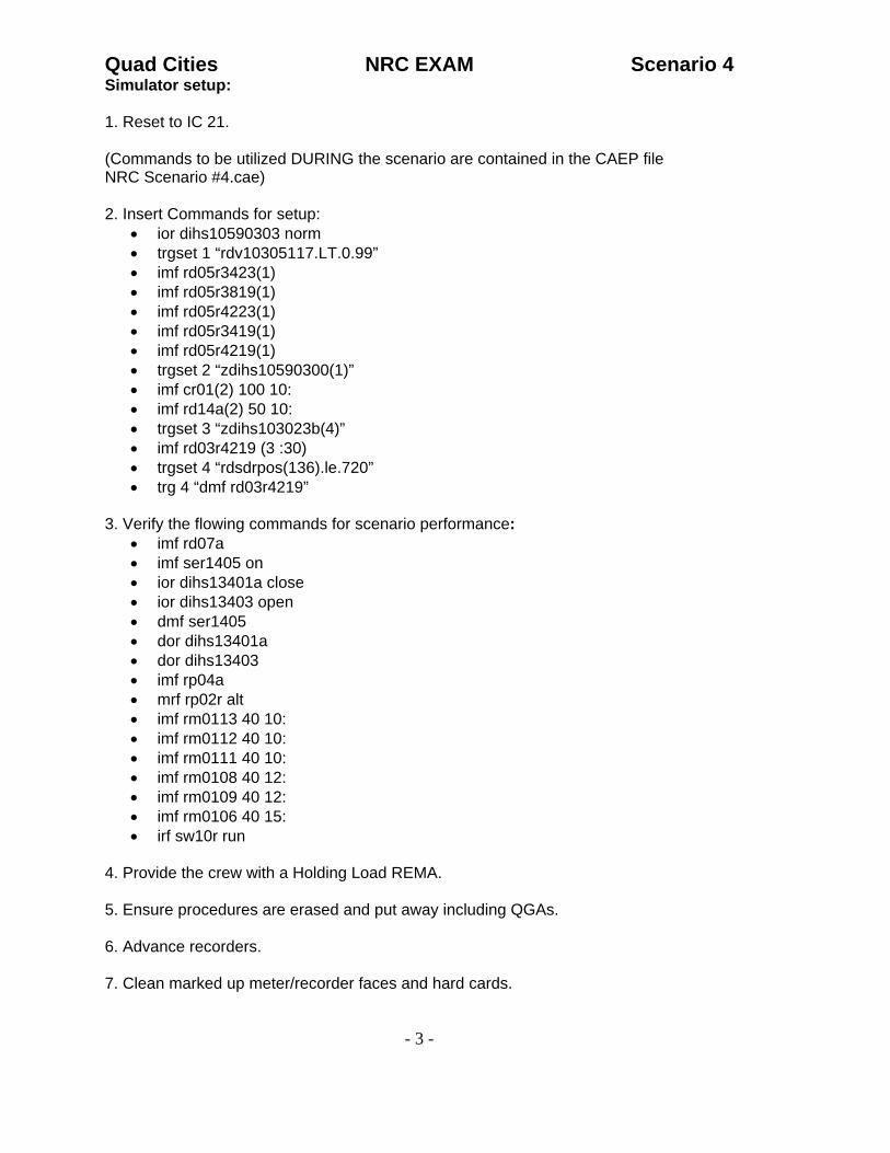
Simulator setup: 1. Reset to IC 21.
(Commands to be utilized DURING the scenario are contained in the CAEP file NRC Scenario #4.cae) 2. Insert Commands for setup:
• ior dihs10590303 norm • trgset 1 “rdv10305117.LT.0.99” • imf rd05r3423(1) • imf rd05r3819(1) • imf rd05r4223(1) • imf rd05r3419(1) • imf rd05r4219(1) • trgset 2 “zdihs10590300(1)” • imf cr01(2) 100 10: • imf rd14a(2) 50 10: • trgset 3 “zdihs103023b(4)” • imf rd03r4219 (3 :30) • trgset 4 “rdsdrpos(136).le.720” • trg 4 “dmf rd03r4219”
3. Verify the flowing commands for scenario performance:
• imf rd07a • imf ser1405 on • ior dihs13401a close • ior dihs13403 open • dmf ser1405 • dor dihs13401a • dor dihs13403 • imf rp04a • mrf rp02r alt • imf rm0113 40 10: • imf rm0112 40 10: • imf rm0111 40 10: • imf rm0108 40 12: • imf rm0109 40 12: • imf rm0106 40 15: • irf sw10r run
4. Provide the crew with a Holding Load REMA. 5. Ensure procedures are erased and put away including QGAs. 6. Advance recorders. 7. Clean marked up meter/recorder faces and hard cards.

Quad Cities NRC EXAM Scenario 4
- 4 -
8. Remove any flags placed by the previous crew.

Quad Cities NRC EXAM Scenario 4
- 5 -
LIST OF POTENTIAL PROCEDURES
− Annunciator Procedures
o 901-5 B-2, Rev. 5 o 901-5 F-2, Rev. 5 o 901-6 F-3, Rev. 1 o 901-6 G-3, Rev. 3
− QCGP 2-3, Rev. 66
− QGA 100, Rev. 9
− QGA 300, Rev. 11
− QGA 500-1, Rev. 13
− QCOA 0300-01, Rev. 16
− QCOA 0300-04 Rev. 15
− QCOA 0300-11, Rev.20
− QCOA 3500-01, Rev. 27
− QCOA 0400-01, Rev. 20
− QOA 7000-01, Rev. 31
− QCOP 3200-05, Rev. 28

Quad Cities NRC EXAM Scenario 4
- 6 -
CREW TURNOVER
1. Plant Conditions:
a.) Unit 1 is operating at 100% power. b.) Unit 2 is operating at 100% power.
c.) Technical Specification limitations:
(1) Unit 1: None (2) Unit 2: None
d.) On Line Risk is Green
. 2.) Evolutions/maintenance for the oncoming shift:
a.) Continue to hold load per QCGP 3-1, Reactor Power Operations. And the REMA.

Quad Cities NRC EXAM Scenario 4
- 7 -
Appendix D Required Operator Actions Form ES-D-2
Quad Cities Scenario No.: 4 Event No.: 1 & 2 Page 1 of 2 NOTE: Event Description: 1A CRD Pump Trip.
Control Rod drift on 1B CRD pump start
Time Position Applicant’s Actions or Behavior
SIM OP: Trip the 1A CRD pump: imf rd07a
ATC Acknowledges annunciator 901-5 B-2, “CRD PP TRIP,” and reports the “1A CRD pump has tripped.”
SRO Sets scram criteria of “2 or more accumulator trouble alarms AND charging water header pressure < 940 psig for 20 minutes.”
ATC Verifies the MO 1-301-2B, 1B PMP DISCH VLV, is closed for the standby pump.
ATC Starts the 1B CRD pump and verifies current is < 34 amps on the 1-302-1B.
SIM OP NOTE: Verify trigger 3 goes true after the 1B CRD pump is started. This will start control rod L-5 drifting in from position 48. Verify trigger 4 goes true at rod position 45 which deletes the rod drift malfunction causing control rod L-5 to settle at rod position 46.
ATC Throttles MO 1-301-2B to maintain 1400-1500 psig discharge pressure.
ATC Closes the MO 1-301-2A in the tripped pump.
ATC Dispatches EO to verify proper operation of running pump.
SIM OP ROLE PLAY: As EO dispatched to the CRD pump, wait 2 minutes and report the 1B CRD pump sounds normal, no leaks, and oil levels are in band. If also requested to check the 1A CRD pump breaker at Bus 13, report “the breaker tripped on overcurrent”.
ATC/BOP Reviews actions of QCOA 0300-01.
ATC Acknowledges 901-5 A-3, “Rod Drift”, and reports control rod L-5 is drifting in.
ATC Refers to QCAN 901-5 A-3, and QCOA 0300-11, Control Rod Drift.

Quad Cities NRC EXAM Scenario 4
- 8 -
Quad Cities Scenario No.: 4 Event No.: 1 & 2 Page 2 of 2 NOTE: Event Description: 1A CRD Pump Trip.
Control Rod drift on 1B CRD pump start
Time Position Applicant’s Actions or Behavior
SRO Notifies Shift Manager and Qualified Nuclear Engineer of control rod L5 drifting in.
ATC Reports control rod L-5 has settled at position 46. Exits QCOA 0300-11 and enters QCOA 0300-04, Mispositioned Control Rod”.
SRO Directs actions of QCOA 0300-04 and directs ATC to withdraw control rod L-5 to position 48.
SIM OP ROLE PLAY: As the QNE, concur with the action to return control rod L-5 to position 48.
ATC Bypasses RWM per QCOP 0207-02 to allow coupling check.
ATC Withdraws control rod L-5 to position 48 and performs a coupling check.
SRO Notifies SOS and Operations Manager.
Proceed to Event 3

Quad Cities NRC EXAM Scenario 4
- 9 -
Appendix D Required Operator Actions Form ES-D-2
Quad Cities Scenario No.: 4 Event No.: 3a Page 1 of 2 Event Description: Emergency Power Reduction for loss of FW Heater String due to 1A1 Heater Level Switch failure.
Time Position Applicant’s Actions or Behavior
SIMOP: Insert the following commands to simulate a failure of the 1A1 Heater level switch (1-3541-32A): imf ser1405 on
ior dihs13401a close ior dihs13403 open
ATC/BOP Acknowledges annunciator 901-6 G-1, “Heater 1A1 Heater High Level,” and verifies the following:
• FCV 1-3101A, 1A1 Emergency Drain Vlv, opens. • MO 1-3401A, Line 1 Htr Inlet Isol Vlv, closed. • MO 1-3402A, Line 1 Htr Outlt Isol Vlv, closed. • MO 1-3403, LP Htr String Byp Vlv, open
ATC/BOP Monitors 1A1 Flash Tank level and reports level is low and dispatches an EO to investigate.
SIM OP ROLE PLAY: As EO dispatched to the 1A1 Flash Tank Level Controller, (LIC 1-3541-9A) wait 3 minutes and report that “level is downscale and you have contacted Electrical Maintenance to assist in troubleshooting”.
ATC/BOP Reports increasing Condensate Demin D/P as indicated on the DPR 1-3340-1, Cond Demin DP, at the 901-6 panel.
SRO Enters and directs actions of QCOA 3500-01 and QCOA 0400-01 and sets scram criteria of reactor power > 105%, or any indication of Core Instabilities.
CT1
SRO Directs Emergency Power Reduction to < 7.6 Mlb/hr Feedwater flow.
CT1
ATC Initiates Emergency Power Reduction by inserting CRAM rods and lowering Recirc pump speeds.
EVALUATOR NOTE: During rapid power reductions, annunciator 901-3 A-2, Main Stm Line Hi Radiation may alarm due to a momentary spike. The operator should verify that MSL radiation monitor readings return to normal after reactor power stabilizes or the annunciator clears.
CREW Monitors and maintains Flow Control Line (FCL) < 100%.
ATC Monitors for indications of core instabilities.
SRO Directs power reduction continued until total Feedwater flow is < 7.6 Mlb/hr.

Quad Cities NRC EXAM Scenario 4
- 10 -
Appendix D Required Operator Actions Form ES-D-2
Quad Cities Scenario No.: 4 Event No.: 3b Page 2 of 2 Event Description: 1A1 Heater Level Switch restoration and closure of LP Heater String Bypass Valve.
Time Position Applicant’s Actions or Behavior
ATC/BOP Monitors D Heater Outlet temperature and Reactor power per QCOA 3500-01, Attachment A, and scrams the reactor if operating below the curve.
ATC/BOP Reports total Feedwater flow is < 7.6 Mlb/hr and annunciator 901-6 G-1 has cleared.
SIM OP ROLE PLAY: When Feedwater flow is < 7.6 Mlb/hr, insert the following commands:
dor dihs13401a dor dihs13403 dmf ser1405
Call in as the EM Supervisor and report “while removing the cover to inspect the 1A1 Heater Level Switch, the switch repositioned. It appears the switch had stuck. A work package will be prepared to clean or replace the switch.”
CT1 SRO Directs closure of MO 1-3403, LP Htr String Byp Vlv, to terminate the
reactivity addition.
CT1 BOP Closes the MO 1-3403, LP Htr String Byp Vlv.
BOP Secures one Reactor Feed pump and one Condensate/Condensate Booster pump per QCOP 3200-05.
Proceed to Event 4

Quad Cities NRC EXAM Scenario 4
- 11 -
Appendix D Required Operator Actions Form ES-D-2
Quad Cities Scenario No.: 4 Event No.: 4 Page 1 of 1 Event Description: RPS A Trip With 5 Control Rod Scram/Manual Scram / Fuel Damage
Time Position Applicant’s Actions or Behavior
SIM OP: Trip RPS A MG Set and verify trigger 1 goes true, scramming 5 control rods: imf rp04a
ATC Reports RPS A has tripped and 5 control rods have scrammed.
ATC Inserts a manual reactor scram IAW QCOA 0300-11
ATC Reports the following: • All rods in. • RPV water level dropped below 0 inches and is recovering with
Condensate and Feedwater system. • RPV pressure is < 1060 psig and controlled by DEHC.
Proceed to Event 5

Quad Cities NRC EXAM Scenario 4
- 12 -
Appendix D Required Operator Actions Form ES-D-2
Quad Cities Scenario No.: 4 Event No.: 5 Page 1 of 2 Event Description: Fuel Damage / North SDV Rupture
Time Position Applicant’s Actions or Behavior
SIM OP: Verify trigger 2 (fuel damage) and trigger 3 (SDV rupture) go true when the Mode Switch is taken to Shutdown. If not, make both triggers true when a full scram is inserted.
SRO Enters QGA 100 on low RPV water level and directs actions.
SRO Directs BOP to verify auto actions for 0 inches RPV water level.
BOP Verifies Group II and Group III isolations complete after RPS A is restored from the alternate power supply.
ATC Performs actions of QCGP 2-3 Attachment A.
ATC Maintains RPV water level band if 0 to 48 inches with Condensate and Feedwater.
SRO Directs RPV cooldown at < 100°F/hr (initially with Main Turbine Bypass valves, then transitions to ADS valves when MSIV’s are closed due to high off-gas radiation levels).
ATC Starts RPV cooldown at < 100°F/hr.
SRO Directs BOP to perform actions of QOA 7000-01.
BOP Performs QOA 7000-01 and restores RPS A on the Alternate supply.
SIM OP ROLE PLAY: If dispatched to restore RPS A from its alternate supply, wait 3 minutes and restore it using: mrf rp02r alt Report the EPA 1A-2 has tripped on underfrequency.
BOP Acknowledges annunciators 901-55/56 A-1, “Drywell High Rad Conc,” and reports Drywell radiation is 30 R/hr and rising.
BOP Acknowledges the following alarms: • 901-3 D-2, Off-Gas Hi Radiation • 901-3 C-2, Off-Gas Hi Hi Radiation • 901-3 A-2, Main Stm Line Hi Radiation • 901-3 D-1, Turb Bldg Hi Radiation
SRO Directs actions of QCOA 1700-04, 1700-05, and 1800-01.
BOP Monitors area radiation levels at the 901-11 panel and evacuates areas as necessary.

Quad Cities NRC EXAM Scenario 4
- 13 -
Appendix D Required Operator Actions Form ES-D-2
Quad Cities Scenario No.: 4 Event No.: 5 Page 2 of 2 Event Description: Fuel Damage / North SDV Rupture
Time Position Applicant’s Actions or Behavior
ATC/BOP Notifies Radiation Protection of area high radiation and request access control established.
ATC/BOP Notifies QNE and Chemistry personnel of high radiation.
BOP Monitors MSL and Off-Gas radiation levels at the 901-2 and 901-10 panels.
SRO Directs closure of all MSIV’s, MSIV drain valves, AO 1-5406 and AO 1-5408A/B.
ATC/BOP Closes all MSIV’s and MSIV drain valves at the 901-3 panel.
ATC/BOP Close the AO 1-5406 and verify the AO 1-5408A and AO 1-5408B close at the 901-54 panel.
Proceed to Event 6

Quad Cities NRC EXAM Scenario 4
- 14 -
Appendix D Required Operator Actions Form ES-D-2
Quad Cities Scenario No.: 4 Event No.: 6 Page 1 of 1 Event Description: Scram Reset Switch Failure
Time Position Applicant’s Actions or Behavior SIM OP: Fail the 1st and 2nd Floor RB Rad Monitor upscale: imf rm0113 40 10:, imf rm0112 40 10:, imf rm0111 40 10:, imf 0108 40 12:, imf rm0109 40 12:, imf rm0106 40 15:
BOP Acknowledges annunciator 901-3 A-1, “Rx Bldg Hi Radiation,” and refers to annunciator procedure.
SRO Enters and directs actions of QGA 300.
ATC/BOP Dispatches EO to start the U-1 EDG Cooling Water Pump.
SIM OP ROLE PLAY: If requested wait approx. 2 minutes and start the U-1 EDGCWP: irf sw10r run
ATC/BOP Dispatches EO to monitor area water levels in the Reactor Building Basement.
SIM OP ROLE PLAY: As EO dispatched to the RB basement, wait approx. 5 minutes and report, “there is no steam or water leaking around the Torus or any of the corner rooms.”
SIM OP ROLE PLAY: As an RP Technician, call in and report, “Steam and water are leaking from the North Scram Discharge Volume. You have verified no other personnel are in the area.”
SRO Directs ATC to reset the reactor scram.
ATC Bypasses the SDV high level, attempts to reset the reactor scram, and reports the scram will NOT reset.
ATC/BOP Continues monitoring Area Radiation and temperatures.
Proceed to Event 7

Quad Cities NRC EXAM Scenario 4
- 15 -
Appendix D Required Operator Actions Form ES-D-2
Quad Cities Scenario No.: 4 Event No.: 7 Page 1 of 1 Event Description: RPV Blowdown on 2 Areas at Max Safe Radiation Levels
Time Position Applicant’s Actions or Behavior ATC/BOP Reports that area radiation levels for the 1st and 2nd Floor Reactor
Building are above max safe levels. SRO Enters QGA 500-1, RPV Blowdown, and directs actions.
SRO Verifies all rods in.
ATC/BOP Reports Drywell pressure < 2.5 psig.
ATC/BOP Reports Torus level > 5 ft.
CT2
SRO Directs ATC/BOP to open all 5 ADS valves and leave switches in MANUAL.
CT2
ATC/BOP Opens all 5 ADS valves and leaves switches in MANUAL.
ATC/BOP Verifies all 5 ADS valves are open by Acoustic Monitor indications on the 901-21 panel.
ATC/BOP Monitor RPV depressurization.
ATC/BOP Report RPV pressure < 100 psig and lowering.
End of Scenario