qtm-hd 6241 qam transcoder module, high definition … are subject to change without notice. ......
TRANSCRIPT

INSTRUCTION MANUAL
One Jake Brown RoadOld Bridge, NJ 08857-1000 USA
(800) 523-6049 • (732) 679-4000 • FAX: (732) 679-4353www.blondertongue.com
©2006 Blonder Tongue Laboratories, Inc. All rights reserved. Specifications are subject to change without notice. Trademarks are the property of their respective owner.
M A D E I N U S A
QT-SeriesQAM TranscoderModel Stock No. DescriptionQTM 6231 QAM Transcoder Module
QTM-HD 6241 QAM Transcoder Module, High Definition
QTM-HD PLUS 6242 QAM, Transcoder Module, High Definition Plus
QTPCM 6232/6232B QT Power Supply & Control Module
QTRC 6233 QAM Transcoder Rack Chassis
QTRA-8 6230 QAM Transcoder Rack Assembly(Contains 8 QTM and a QTPCM in a QTRC)
QTRA-8 & RFCS 6229 QAM Transcoder Rack Assembly(Contains 8 QTM and a QTPCM in a QTRC with a QTRFCS)
AccessoriesModel Stock No. DescriptionQTRFCS 6234 QT RF Combiner and Splitter
(Contains QTRFC, 6234-1 and QTRFS, 6234-2)
QTRFCS-2 6225 QTRFC Combiner and Splitter with 2 Input Splitter (Contains QTRFC, 6234-1 and QTRFS, 6225-2)
BFP-19-IV 3988 1.75” Vented Blank Panel
QTSPS 6239/6239B QT Standby Power Supply with Headend Fan
HDA-16-860-16 6240-16 Headend Distribution Amplifier (with 16 dB Gain, 16 Ports)
HDA-8-860-20 6240-08 Headend Distribution Amplifier (with 20 dB Gain, 8 Ports)
QC-HSK 2720 QCentral Remote Monitoring and Control Software
QTHF 6235 Headend Fan
HWS 2727 Headend Web Server
651210400E

2 QT-SeriesInstruction Manual
We recommend that you write the following information in the spaces provided below.
The information contained herein is subject to change without notice. Revisions may be issued to advise of such changes and/or additions.
Correspondence regarding this publication should be addressed directly to:
Blonder Tongue Laboratories, Inc.
One Jake Brown Road
Old Bridge, NJ 08857
Document Number: 651210400
Printed in the United States of America.
All product names, trade names, or corporate names mentioned in this document are acknowledged to be the proprietary property of the registered owners.
This product incorporates copyright protection technology that is protected by U.S. patents and other intellectual property rights. Reverse engineering or disassembly is prohibited.
Purchase Location Name:
Purchase Location Telephone Number:
Transcoder Digital Address:
Purchase Location Name:
Purchase Location Telephone Number:
Transcoder Digital Address:

3QT-Series Instruction Manual
The lightning flash with arrow-head symbol within an equilateral triangle is intended to alert you to the presence of uninsulated “dangerous voltage” within the product’s enclosure that may be of sufficient magnitude to consti-tute a risk of electrical shock to persons.
WARNING: TO PREVENT FIRE OR SHOCK HAZARD, DO NOT EXPOSE THIS UNIT TO RAIN OR MOISTURE
NOTE TO CATV SYSTEM INSTALLERThis reminder is provided to call the CATV System Installer’s attention to Article 820-40 of the NEC that
provides guidelines for proper grounding and, in particular, specifies that the cable ground shall be connected to the grounding system of the building, as close to the point of cable entry as practical.
!The exclamation point within an equilateral triangle is intended to alert you to the presence of important operating and main-tenance (servicing) instructions in the literature accompanying the product.
TO REDUCE THE RISK OF ELECTRICAL SHOCK, DO NOT REMOVE COVER FROM THIS UNIT. NO USER-SERVICEABLE PARTS INSIDE. REFER SERVICING TO QUALIFIED SERVICE PERSONNEL.

4 QT-SeriesInstruction Manual
Safety Instructions
➥ Read all safety and operating instructions before you operate the transcoder.
➥ Retain all safety and operating instructions for future reference.
➥ Heed all warnings on the transcoder and in the safety and operating instructions.
➥ Follow all installation, operating, and use instructions.
➥ Unplug the transcoder from the AC power outlet before cleaning. Use only a damp cloth for cleaning the exterior of the transcoder.
➥ Do not use accessories or attachments not recommended by Blonder Tongue, as they may cause hazards, and will void the warranty.
➥ Do not operate the transcoder in high-humidity areas, or expose it to water or moisture.
➥ Do not place the transcoder on an unstable cart, stand, tripod, bracket, or table. The transcoder may fall, causing serious personal injury and damage to the transcoder. Install the transcoder only in a mounting rack designed for 19” rack-mounted equipment.
➥ Do not block or cover slots and openings in the transcoder. These are provided for ventilation and protection from overheating. Never place the transcoder near or over a radiator or heat register. Do not place the transcoder in an enclosure such as a cabinet without proper ventilation. Do not mount equipment in the rack space directly above or below the transcoder.
➥ Operate the transcoder using only the type of power source indicated on the marking label. Unplug the transcoder power cord by gripping the plug, not the cord.
➥ The transcoder is equipped with a three-wire ground-type plug. This plug will fit only into a ground-type power outlet. If you are unable to insert the plug into the outlet, contact an electrician to replace the outlet. Do not defeat the safety purpose of the ground-type plug.
➥ Route power supply cords so that they are not likely to be walked on or pinched by items placed upon or against them. Pay particular attention to cords at plugs, convenience receptacles, and the point where they exit from the unit.
➥ Be sure that the outdoor components of the antenna system are grounded in accordance with local, federal, and National Electrical Code (NEC) requirements. Pay special attention to NEC Sections 810 and 820. See the example shown in the following diagram:
WARNING!
You should always follow these instructions to help ensure against injury to yourself and damage to your equipment.

5QT-Series Instruction Manual
Safety Instructions - continued
➥ We strongly recommend using an outlet that contains surge suppression or ground fault protection. For added protection during a lightning storm, or when the transcoder is left unattended and unused for long periods of time, unplug it from the wall outlet and disconnect the lines between the transcoder and the antenna. This will prevent damage caused by lightning or power line surges.
➥ Do not locate the antenna near overhead power lines or other electric light or power circuits, or where it can fall into such power lines or circuits. When installing the antenna, take extreme care to avoid touching such power lines or circuits, as contact with them can be fatal.
➥ Do not overload wall outlets or extension cords, as this can result in a risk of fire or electrical shock.
➥ Never insert objects of any kind into the transcoder through openings, as the objects may touch dangerous voltage points or short out parts. This could cause fire or electrical shock.
➥ Do not attempt to service the transcoder yourself, as opening or removing covers may expose you to dangerous voltage and will void the warranty. Refer all servicing to authorized service personnel.
➥ Unplug the transcoder from the wall outlet and refer servicing to authorized service personnel whenever the following occurs:
❏ The power supply cord or plug is damaged;
❏ Liquid has been spilled, or objects have fallen into the transcoder;
❏ The transcoder has been exposed to rain or water;
❏ The transcoder has been dropped or the chassis has been damaged;
❏ The transcoder exhibits a distinct change in performance.
➥ When replacement parts are required, ensure that the service technician uses replacement parts specified by Blonder Tongue. Unauthorized substitutions may damage the transcoder or cause electrical shock or fire, and will void the warranty.
➥ Upon completion of any service or repair to the transcoder, ask the service technician to perform safety checks to ensure that the transcoder is in proper operating condition.
Returning Product for Repair (or Credit)Returning Product for Repair (or Credit)A Return Material Authorization (RMA) Number is required on all products returned to Blonder Tongue, regardless if the product is being returned for repair or credit. Before returning product, please contact the Blonder Tongue Service Department at 1-800-523-6049, Ext. 4256 or visit our website: www.blondertongue.com for further information.

6 QT-SeriesInstruction Manual
IntroductionThe QT Series is a Modular QPSK to QAM Transcoder supporting up to eight QAM Transcoder Modules, interfaced with a Power & Control Module housed in a specially designed 3RU chassis.The unit transcodes any 24-36 MHz wide QPSK modulated satellite signal to a 6 MHz wide QAM modulated IF signal and translates it to any CATV RF channel assignment in the 54-864 MHz frequency band.The QT Series features a back-lit LCD display with front panel accessible push button controls providing access to all vital unit information, facilitating easy set-up and troubleshooting.Interfacing the QT with Blonder Tongue’s QCentral computer software or HWS provides off-site, remote operation and control including digital adjustment of the QAM RF output level.
Features• Modular Design Allows One to Eight QAM Transcoder Modules in Three Rack Spaces• Fully Agile Output Frequency Range of 54-864 MHz (CATV Ch. 2-135)• Fully Agile Input Transponder Frequency Range of 950-2150 MHz• Provides HDTV Quality Using QTM-HD Modules• Flash Memory Integrated for Easy Firmware Upgrades• Convenient Level Setting and Adjustment with CW Mode Capability• Valuable QPSK SNR Data to Facilitate Easy Antenna Peaking• Hot Swappable Transcoder Modules• Back-Lit LCD Display Panel with Front Panel Accessible Push Button Controls Provides Access to All Vital Unit
Information and Makes Set-Up and Troubleshooting a Breeze• Off-Site Remote Operation and Control Including Digital Adjustment of the QAM RF Output Level with High
Performance QCentral Computer Software Internet Connection• QTM-HD Plus Provides QAM 1024 Capability• HWS Provides Remote Operation and Control over an Internet Connection

7QT-Series Instruction Manual
The Unit
Front Panel - QT
UP
DN
L R
ENTERQTM
QAM TRANSCODERMODULE
STATUS
QTMQAM TRANSCODER
MODULE
STATUS
QTMQAM TRANSCODER
MODULE
STATUS
QTMQAM TRANSCODER
MODULE
STATUS
QTMQAM TRANSCODER
MODULE
STATUS
QTMQAM TRANSCODER
MODULE
STATUS
QTMQAM TRANSCODER
MODULE
STATUS
QTMQAM TRANSCODER
MODULE
STATUS
1
2 3
QT PCMPOWER & CONTROL MODULE
1. Unit Status Indicator - Provides feedback to user based on the following LED conditions:a) Solid Green ON - Indicates valid QPSK and QAM lockb) Flash ON/OFF - QAM signal is in OFF or CW mode c) Flash 1x, 2x or 3x and Pause OFF - Indicates possible upconverter problem, or possible problem with power cabled) Flash 4x and Pause OFF - Indicates possible QAM modulator problem, check
input transponder frequency and data rate to correct (check to make sure in “Auto Mode”)
2. Backlit LCD - 8 character, 2 line Liquid Crystal Display screen used to interact with user to display unit information.
3. Push Button Navigation Controls - Buttons used to navigate between menus and enter unit information.
1. Power Cord Socket - The unit power cord plug socket.2. Fuse Holder - 4.0 Amp., 250V DC, Slo Blo fuse.3. Module Power/Data Cables - 2 cable sets with a 12-pin male connector used to deliver power and data
to each QT unit.4. RS232 Serial Data Ports - Used to plug into and daisy chain QT units for remote monitoring
and configuration.5. Power IN - 12-pin female connector used to plug-in the optional Standby Power unit for redundant support.6. QPSK L-Band Input - Independent 75 Ohm RF connector for feeding appropriate QPSK L-Band satellite
input signal.7. QAM RF Output - Independent 75 Ohm QAM RF Output.8. Power/Data - 12-pin female connector used to plug-in cable for respective module to deliver power and data.
Rear Panel - QT
MODEL: QT PCMSTOCK NO.: 6232
117V 2.0A 60 HzFUSE 4.0A, 250VDC SB
STANDBY
INDATAOUT
POWERIN
POWER/DATA
POWER/DATA
MOD5-8
MOD1-4
QAMRF
OUT
L-BAND IN
POWER/DATA
QAMRF
OUT
L-BAND IN
POWER/DATA
QAMRF
OUT
L-BAND IN
POWER/DATA
QAMRF
OUT
L-BAND IN
POWER/DATA
QAMRF
OUT
L-BAND IN
POWER/DATA
QAMRF
OUT
L-BAND IN
POWER/DATA
QAMRF
OUT
L-BAND IN
POWER/DATA
QAMRF
OUT
L-BAND IN
POWER/DATA
1 5 6
73 8
2 4
Model, Stock No.
QTM
QTM-HD
QTM-HD PLUS
6231
6241
6242
Model, Stock No.
QTM
QTM-HD
QTM-HD PLUS
6231
6241
6242
Model, Stock No.
QTM
QTM-HD
QTM-HD PLUS
6231
6241
6242
Model, Stock No.
QTM
QTM-HD
QTM-HD PLUS
6231
6241
6242
Model, Stock No.
QTM
QTM-HD
QTM-HD PLUS
6231
6241
6242
Model, Stock No.
QTM
QTM-HD
QTM-HD PLUS
6231
6241
6242
Model, Stock No.
QTM
QTM-HD
QTM-HD PLUS
6231
6241
6242
Model, Stock No.
QTM
QTM-HD
QTM-HD PLUS
6231
6241
6242
Drawings are samples for illustration purposes only and are not to scale

8 QT-SeriesInstruction Manual
SpecificationsTechnical Specifications For QTM and QTM-HDSatellite QPSK InputInput Frequency Range: Agile 950-2150 MHz QPSK Bandwidth: Up to 36 MHzFrequency Step: 1 MHzCapture Range: ±5 MHzInput Level Range: -65 to -20 dBmRF Input Impedance: 75 OhmReturn Loss: 8 dB min.FEC Decoding: DVB, DigiCipher® UpgradableSymbol Rate: 2 to 45 MspsCode Rate: Viterbi Auto RecognitionI - Q Format: Normal / Inverted8PSK & QPSK Turbo for QTM-HDQAM OutputOutput Frequency Range: Agile 54-864 MHzChannel Range: CATV Ch. 2-135QAM Bandwidth: 6 MHzOutput Level: +40 dBmVDisplay Error: ±2 dBOutput Level Adjustable Range: 30-40 dBmVModulation Mode QTM: 16, 32, 64, 128, 256 QAM
(8PSK, QPSK Turbo & 256 QAM Capable with QTM-HD only)
Symbol Rate: 1 Msps to 6.9 MspsSpectral Inversion: Auto RecognitionCarrier Suppression: 45 dBRoll Off: 12, 15, 18 %QAM SNR: >40 dBMER QTM: 38 to 42 dB QTM-HD: 40 to 43 dBRF Output Impedance: 75 Ohm Spurious: -60 dBcBroadband Noise: -75 dBc min. (4 MHz BW @40 dBmV Output)Phase Noise QTM-HD @ 10 kHz: -97 dBc QTM @ 10 kHz: -90 dBc Frequency Stability: ± 10 kHz
QAM I/Q Phase Error: <1 DegreeI/Q Amplitude Imbalance: <1 %Controls and IndicatorsPCM Computer Control: 2 RJ11 Rear Panel RS232 Connectors Backlit Liquid Crystal Display (LCD) 5 Navigation/Enter Push ButtonsQTM, QTM-HD Unit Status Indicator: 1 Green LED Per ModuleTechnical Specifications For QTM and QTRA-8MechanicalChassis Dimensions: 5.25 x 19.0 x 12 inchesQTM Dimensions: 5.25 x 10.625 x 1.5 inchesMounting: Standard EIA Unit Height 5.25” x 19”
Wide Rack MountQTM Unit Weight: 1.7 lbsQTRA-8 Weight: 28 lbsQTM PowerRequirement: 100 to 265 VAC, 1AFrequency: 50 to 60 HzPower Consumption (QTM + PCM)
Fuse: 4 Amp, 250 VDC, SBQTM-HD PowerRequirement: 100 to 265 VAC, 1AFrequency: 50 to 60 HzPower Consumption (QTM-HD & PCM)
QTM-HD PLUS PowerRequirement: 100 to 265 VAC, 1AFrequency: 50 to 60 Hz
Power Consumption (QTM-HD PLUS & PCM PLUS)
EnvironmentalOperating Temperature: 0 to 50 °CStorage Temperature: -20 to 70 °CHumidity: 0 to 90 % RH
QTM’s: 1 2 3 4 5 6 7 8
Watts: 17 28 40 52 64 75 86 98
QTM’s: 1 2 3 4 5 6 7 8
Watts: 17 28 40 52 64 75 86 98
QTM’s: 1 2 3 4 5 6 7 8
Watts: 17 28 40 52 64 75 86 98
QTM’s: 1 2 3 4 5 6 7 8
Watts: 17 28 40 52 64 75 86 98
QTM’s: 1 2 3 4 5 6 7 8
Watts: 17 28 40 52 64 75 86 98
QTM’s: 1 2 3 4 5 6 7 8
Watts: 17 28 40 52 64 75 86 98
QTM’s: 1 2 3 4 5 6 7 8
Watts: 17 28 40 52 64 75 86 98
QTM’s: 1 2 3 4 5 6 7 8
Watts: 17 28 40 52 64 75 86 98
QTM-HD: 1 2 3 4 5 6 7 8
Watts: 20 31 42 55 68 82 94 107
QTM-HD: 1 2 3 4 5 6 7 8
Watts: 20 31 42 55 68 82 94 107
QTM-HD: 1 2 3 4 5 6 7 8
Watts: 20 31 42 55 68 82 94 107
QTM-HD: 1 2 3 4 5 6 7 8
Watts: 20 31 42 55 68 82 94 107
QTM-HD: 1 2 3 4 5 6 7 8
Watts: 20 31 42 55 68 82 94 107
QTM-HD: 1 2 3 4 5 6 7 8
Watts: 20 31 42 55 68 82 94 107
QTM-HD: 1 2 3 4 5 6 7 8
Watts: 20 31 42 55 68 82 94 107
QTM-HD: 1 2 3 4 5 6 7 8
Watts: 20 31 42 55 68 82 94 107
QTM-HD PLUS: 1 2 3 4 5 6 7 8
Watts: 20 31 42 55 68 82 94 107
1 2 3 4 5 6 7 8
Watts: 20 31 42 55 68 82 94 107
1 2 3 4 5 6 7 8
Watts: 20 31 42 55 68 82 94 107
1 2 3 4 5 6 7 8
Watts: 20 31 42 55 68 82 94 107
1 2 3 4 5 6 7 8
Watts: 20 31 42 55 68 82 94 107
1 2 3 4 5 6 7 8
Watts: 20 31 42 55 68 82 94 107
1 2 3 4 5 6 7 8
Watts: 20 31 42 55 68 82 94 107
1 2 3 4 5 6 7 8
Watts: 20 31 42 55 68 82 94 107

9QT-Series Instruction Manual
Technical Specifications For QTRFCSRF Combiner - (Stock No. 6234-1)Inputs: 8Outputs: 1Insertion Loss 54-500 MHz: 9.7 dB 500-860 MHz: 10.7 dBIsolation Between Ports 1-4: 30 dBIsolation Between Ports 5-8: 45 dBIsolation Between Group 1-4 to Group 5-8; 45 dBInput Return Loss: 23 dBOutput Return Loss: 23 dBRF L-Band Splitter - (Stock No. 6234-2)Input: 1Outputs: 8Insertion Loss 950-1750 MHz: 13.5 dB 1750-2050 MHz: 14.5 dBIsolation Between Any Combination of Input Ports (1-8): 20 dBInput Return Loss: 16 dBOutput Return Loss: 16 dB2 Input L-Band Splitter - (Stock No. 6225-2)2 Input L-Band Splitter - (Stock No. 6225-2)2 Input L-Band SplitterInputs: 2Output: 4 per InputInsertion Loss: 950-1750 MHz: 8.5 dB 1750-2050 MHz: 9 dBIsolation Between Ports (1-4) (5-8): 20 dBMechanicalQTRFC (WxHxD): 14.39 x 1.5 x 2.91 inchesQTRFS (WxHxD): 9.69 x 1.52 x 2.92 inches
Technical Specifications For QTPCMElectrical Output Connectors to QTPCM 6232 6232BOutput Voltage Current Max. Current Max.
+5 VDC 5.5 A 7.0 A +10 VDC 3.0 A 3.0 A +2.9 VDC 0.12 A 0.12 A +3.3 VDC 8.5 A 10.0 AEnvironmentalOperating Temperature: 0 to 50 °CStorage Temperature: -20 to 70 °CHumidity: 0 to 90 % RHMechanicalDimensions (WxHxD): 19.0 x 1.75 x 14.5 inchesWeight: 6.5 lbs.
Technical Specifications for Headend Web Server
Programming Capabilities
IP Addressing Modes: Fixed or DHCP
Front Panel Settable User Name & Password
Front Panel Settable Headend Name
HTTP Web Browser Interface Requires No Additional SoftwareMechanical
Dimensions: 10.0 x 19.0 x 1.75 inches
Weight: 4 lbs.
Mounting: Standard EIA Unit Height10.0” x 19” Wide Rack Mount
Controls & Connectors
Front Panel: Backlit Liquid Crystal Display (LCD)
5 Navigation/Enter Push Buttons3 Green Ethernet Status LEDs
Rear Panel Serial Ports: RS 232, RJ-11 Port for Connection QT Headend RS 232, RJ-11 Port for Firmware Upgrade Only
Rear Panel Ethernet Port: RJ-45
Physical Layer: 10BaseT RJ-45 WAN/LAN Ethernet Port
Media Access and Link Layers: Per IEEE 802.3 (Ethernet)AC Power
Voltage: 117 ± 10% VAC
Frequency: 60 Hz
Power Consumption: 2W
Fuse: 0.25AEnvironmental
Operating Temperature Range: 0 to 50°C
Storage Temperature Range: -20 to 70°C
Humidity: 0 to 90 % RH

10 QT-SeriesInstruction Manual
Installing the Transcoder
Installing the Transcoder in a RackInstalling the Transcoder in a RackMountingThe transcoder chassis is 5.25 inches tall, 19 inches wide, and 12 inches deep. You can mount the transcoder in a standard EIA, 24 inch (610 mm) deep, enclosed rack. Secure the transcoder chassis front panel to the rack by inserting four machine screws, with cup washers, through the four mounting holes in the front panel.
WARNING!
Optional Remote Monitoring & Control
QCentral Remote Monitoring & Control SoftwareQCentral Remote Monitoring & Control SoftwareAn optional Remote Monitoring & Control Software package (QCentral) is available from Blonder Tongue. This custom software application is designed to be used for the ability to monitor and configure a Transcoder headend. The software is a program that can be used locally in the direct connect mode via a null modem cable or remotely in the dial out mode using an external RS-232 serial modem at the headend and the remote site. • The software features a user friendly graphical interface and is compatible with widely available Windows®
based computers.• The software allows the operator to create a unique file for each independent transcoder headend. The operator
can then access the software to monitor, control and configure the units. • The QAM output signal can be remotely turned off allowing the operator the ability to "remotely heal" a
problem transcoder channel by shutting it down and activating a spare transcoder. The transponder signal from the problem transcoder can be activated on the spare and the output QAM signal placed on the previous output channel within the unit range.
• A QCentral Headend Starter Kit is available which includes all of the hardware interconnect components needed for a QT Headend to directly connect and control the headend. The external modem is purchased separately. The Starter Kit can be ordered from Blonder Tongue as Stock No. 2720.
• Single Unit Software Licenses are provided free of charge. They can be obtained by sending the complete unit address (found in the Advanced Interactive Sequence, see Operating Instructions, Level 4) via email to: [email protected]
When installing one or more QT units in a headend rack, it is recommended to leave a 1 rack unit space (1.75” high) between units to maximize air flow, but it is not required. This space helps to reduce heat build-up in a headend rack and will help to extend the product life span.
IMPORTANT! DO NOT block the unit’s ventilation holes.
For safe and reliable operation, the transcoder requires a proper ground connection for the third prong of the transcoder power cord plug

11QT-Series Instruction Manual
Headend Web Server (HWS)Headend Web Server (HWS)The Headend Web Server (HWS) from Blonder Tongue allows an operator the means to remotely access a QAM Transcoder Series headend from anywhere in the world using a web browser over the Internet without requiring any additional software to be installed. The HWS is an add-on hardware based solution housed in a single height, rack mountable unit. It features a built-in web server that hosts software just like the QCentral software to communicate to the QT headend. Just like the original QCentral software, the HWS is a valuable addition so that an operator can quickly and painlessly get real time information from a remote headend location to troubleshoot and even fix a field failure from the business office or anywhere any internet connection is available. The easy to use interface provides many functions, such as display and control of the input transponder frequency, the output channel, digital signal level, the signal to noise ratio as well as the ability to remotely turn off the QAM signal and turn on a hot spare unit. We have built in many advanced features such as DHCP or static IP support as well as 2 levels of password control including read/write and read only access modes.The Headend Web Server is the perfect tool for the QAM Transcoder digital headend. It offer’s the ultimate customer service solution for remote and unmanned headend locations with it’s user activated capability to “remotely diagnose and heal a field problem” and eliminating the need for a costly truck roll or lengthy downtime. Contact Blonder Tongue today to get your Headend Web Server for the QT Series.
QAM Signal Level TestingThis section describes the preferred method for measuring and setting the QAM output level of the unit. It requires the ability to output a CW (carrier wave) QAM signal.
QAM Signal Level in CW ModeQAM Signal Level in CW ModeThe CW QAM signal is used to provide the true equivalent signal level for the QAM carrier. The QT Series is capable of supplying the output QAM signal in CW mode. This simplifies the level measurement process dramatically because the level does not need to be adjusted for the limitation in analyzer bandwidth settings. After setting the appropriate level in CW mode, the modular transcoder is changed back to normal mode.Any meter that can measure CW Carrier Power Level can be used. The CW Carrier Level is equal to the QAM Power Level that will be presented in normal mode.

12 QT-SeriesInstruction Manual
Mechanical Assembly
The ModulesThe QT consists of 3 core modules. QTPCM - QT Power & Control Module QTM - QT QAM Transcoder Module QTRC - QT Rack Chassis
QT Rack Chassis
QT - Power Supply & Control Module (QTPCM)
MODEL: QT PCMSTOCK NO.: 6232
117V 2.0A 60 HzFUSE 4.0A, 250VDC SB
STANDBY
INDATAOUT
POWERIN
POWER/DATA
POWER/DATA
MOD5-8
MOD1-4
UP
DN
L R
ENTER
QT PCMPOWER & CONTROL MODULE
QTMQAM TRANSCODER
MODULE
STATUS
Drawings are samples for illustration purposes only and are not to scale
Front
Front
Rear
QTM-HDHIGH DEFINITION
QAM TRANSCODERMODULE
STATUS
Front
QAMRF
OUT
L-BAND IN
Model, Stock No.
QTM
QTM-HD
QTM-HD PLUS
6231
6241
6242
POWER/DATA
Rear
QTM/QTM-HD - QAMTranscoder Module

13QT-Series Instruction Manual
Installing the Modules in the ChassisInstalling the Modules in the ChassisThe following are the recommended instructions for installation of the modules in a chassis: 1. Mount the QTPCM module in the chassis by gently sliding it into position on the far right most position of
the chassis (facing the front). 2. Tighten the front and rear retaining screw to secure the module in place. 3. Mount all of the appropriate QT modules in the same manner. 4. Install the QTRFCS Combiner/Splitter. If the QTRFCS is not installed, you must install it. 5. Wire the appropriate L-Band input coaxial cables to the QT Modules “QPSK IN L-Band” F connector. 6. Wire the output of each module from the “QAM RF OUT” F connector to the appropriate combining
device. 7. Insert the appropriate power/data cables into the QTPCM 50-pin female connectors labeled “MOD 1-4
and MOD 5-8 POWER/DATA”. ➣ NOTE: Make sure the QTPCM connectors are secure
8. Slightly loosen rear retaining screw on QTPCM and Module #8 (nearest to QTPCM). Slide the cable wire bracket down over the power/data cables (see example below. The cable wire bracket is provided to secure the cable harness in place). Position the cover notches under the retaining screws and tighten screws.
9. Connect the 12-pin power/data cables labeled module 1 to 8 from the QTPCM to the particular transcoder module to the female 50-pin connector labeled “MOD 1-4 and MOD 5-8 POWER/DATA”.
➣ NOTE: Make sure the appropriately labeled cable is connected to the corresponding module. This is done to ensure that the correct module is displayed by the LCD and is actually being communicated with correctly. Keep in mind that the modules are numbered 1 to 8 from left to right on the front and will then be housed 1 to 8 from right to left on the rear.
10. Connect the 12-pin power/cable from the standby power unit to the “Power In” connector of the QTPCM if applicable. The standby power unit can be mounted in the rack or in any easily accessible location.
➣ NOTE: You must connect A/C power to the QTPCM before you connect power from the standby power unit to prevent the unit from immediately going to standby power mode.
11. Connect the A/C power cord to the QTPCM.
QT - Module Loading Front View
Cable Wire Bracket

14 QT-SeriesInstruction Manual
Fully Populated QT Rear View
32 Transcoder Fully Populated QT Front View
8 QAM Channel Combined Combiner
QTRA-8 (3RU)
Modules 1-4Modules 5-8 L-Band Splitter
Blank Panel
QTSPS

15QT-Series Instruction Manual
QAM Transcoder Module Programming RecommendationsQAM Transcoder Module Programming RecommendationsThe following information is provided as a reference to permit optimum performance of the QAM transcoder headend. • DVB 64 & 128 QAM Signals occupy a bandwidth of up to 5.75 MHz • DVB 256 QAM Signals occupy a bandwidth of up to 6.43 MHz • A Standard CATV channel bandwidth is 6.0 MHz • It is recommended to not insert high definition signals that use 256 QAM adjacent to other 256 QAM
high definition signals. • It is recommended to alternate 64 QAM or 128 QAM signals with 256 QAM signals.
������������������������������
������������������������
Signal Overlap Can Occurwith Adjacent 256 Signals
256 QAM 256 QAM
���������������������������������������������������������������
������������
�������
������������
�������
• Placing 256 QAM carriers adjacent to other 256 QAM signals will cause an approximate 3 dB MER degradation of the signal.
QAM Transcoder Power Supply Usage RecommendationsQAM Transcoder Power Supply Usage RecommendationsIt is recommended to only use a maximum of 6 QTM-HD and/or QTM-HD Plus modules with a QTPCM # 6232 in a single rack unit. A QTPCM Plus # 6232B is recommended when 6 to 8 QTM-HD and/or QTM-HD Plus modules are used in a single rack unit.

16 QT-SeriesInstruction Manual
Replacing a QAM Transcoder ModuleReplacing a QAM Transcoder ModuleThe following are the recommended instructions for replacing a QAM Transcoder Module (QTM, QTM-HD, or QTM-HD Plus) while the complete unit is operating: 1. Disconnect the 12-pin power/data cable from the QT Module. 2. Disconnect the RF coaxial cables. 3. Physically remove the QT module from the chassis by loosening the thumbscrew located on the front panel
and the retaining screw on the rear. 4. Physically replace the new QT module in the chassis and tighten rear and front retaining screws. 5. Reconnect all RF coaxial cables. (Ensure the correct cable is wired to the input and output accordingly) 6. Reconnect the 12-pin power/data cable to the module from the QTPCM. ➣ NOTE: Make sure the appropriately labeled cable is connected to the corresponding module.
This is done to ensure that the correct module is displayed by the LCD and is actually being communicated with correctly. Keep in mind that the modules are numbered 1 to 8 from left to right on the front and will then be housed 1 to 8 from right to left on the rear.
When a single QT Module is replaced, the QTPCM changes the setting on the new module to match the old settings. This is intended to make a swap out as simple as possible by minimizing the need to reprogram a QT Module in a swap out condition. This change is not immediate and it may take up to 1 minute before the settings are complete.
Replacing a QTPCMReplacing a QTPCMThe following are the recommended instructions for replacing a Power Supply & Control Module (QTPCM): 1. Remove the standby power cable from the Power In port, if applicable. 2. Remove the A/C power from the QTPCM. 3. Loosen the rear retaining screw and remove the cable wire bracket. 4. Remove the 50-pin power/data cables from the QTPCM. 5. Loosen the front panel retaining thumbscrews. 6. Remove the module from the chassis. 7. Physically replace the new QTPCM in the chassis. 8. Tighten the rear and front retaining screws to secure the module in place. 9. Reconnect the 50-pin power/data cables to the new QTPCM. ➣ NOTE: Make sure the appropriately labeled cable is connected to the corresponding module. This is done
to ensure that the correct module is displayed by the LCD and is actually being communicated with correctly. Keep in mind that the modules are numbered 1 to 8 from left to right on the front and will then be housed 1 to 8 from right to left on the rear.
10. Connect the A/C power cord to the QTPCM.The unit will now reboot. The QTPCM will read the programming information from each QT Module and overwrite its own information from each respective QT Module and display the information accordingly on the LCD. This is designed to make a swap out as simple as possible by minimizing the need to reprogram a QTPCM in a swap out condition. After this installation, a user may reprogram any variable if desired.
11. Reconnect Standby Power after boot-up, if applicable.

17QT-Series Instruction Manual
QT - Operating Interface Instructions
IntroductionThe Blonder Tongue QT Transcoder series uses an easy to read Back-lit LCD (liquid crystal display) and push button switches to control and monitor the QT Modules. The following information describes the LCD methodology and approach. It is broken down into 4 levels of menu interaction described below.
UP
DN
L R
ENTER
QT PCMPOWER & CONTROL MODULE
QT - LCD & Front Panel Navigation Controls
QT - Boot-Up Display Sequence
Level 1 - Boot-Up Display SequenceLevel 1 - Boot-Up Display SequenceWhen the unit is first plugged in for use, the QTPCM interrogates the potential transcoder connections and displays the appropriate module condition on the LCD readout as depicted below.
#1 ISPRESENT
ADDRESS00004455
PRIMARYPOWER
#2 NOTPRESENT
#3 ISPRESENT
#4 ISPRESENT
#5 ISPRESENT
QTM ISREADY
#6 ISPRESENT
#7 ISPRESENT
#8 ISPRESENT
1. Each control module has a unique module address that is set at the factory which is displayed first after the power type. This address is used for remote software capability.
2. Each QAM transcoder module status is identified and reported on the LCD. If a module is identified it is listed as present or not present if not connected.
It is during this cycle that the control module is determining the programming status of each module. Basically, the control module determines if the programming information of the module or it’s own is to be used. This is designed to make module swaps as simple as possible. (See the previous section on replacing a module for details.)
3. Upon completion of the boot-up sequence the QT is ready for use and will proceed to the loop display sequence.
CAUTION DO NOT push any switches on the control module during this sequence as it will NOT respond until it displays "QTM IS READY".

18 QT-SeriesInstruction Manual
#1 INPUTSNR 15.0
#1 OUTCH 111
#2 NOTPRESENT
#3 INPUTNOT LOCK
#3 OUTCH 112
#3 INPUT1563 MHz
#4 INPUTSNR 13.6
#4 OUTCH 113
#4 INPUT1003 MHz
#5 INPUTSNR 14.2
#5 OUTCH 115
#5 INPUT1592 MHz
#6 INPUTSNR 12.8
#6 OUTCH 119
#6 INPUT1032 MHz
#7 INPUTSNR 14.0
#7 OUTCH 120
#7 INPUT1061 MHz
#8 INPUTSNR 12.2
8 OUTCH 122
#8 INPUT1651 MHz
#1 INPUT974 MHz
QT - Loop Display Sequence
1. The top row displays the status for module 1. The following rows display the status information for the remaining modules.
2. The first column displays the SNR Input status of the respective module. If a valid Input signal lock is achieved, the readout will display the estimated Input SNR in dB. If a module is not detected the readout will display the respective module as Not Present. If a Input Lock is not achieved, but the module is present, the readout will display Input Not Lock. 3. Column 2 indicates the output channel information for the respective module. 4. Column 3 indicates the input L-Band frequency information for the respective module.
Level 2 - Loop Display SequenceLevel 2 - Loop Display SequenceAfter the unit has displayed the boot-up sequence it proceeds to the loop sequence. In this mode the LCD displays the actual module status as depicted by the diagram below. This is referred to as the loop sequence because this information is constantly displayed in a scrolling fashion on the LCD readout. The loop sequence may be interrupted at any time by pressing the any of the arrow keys. The diagram is broken up into 8 rows to reflect the eight respective modules that can populate the rack chassis.

19QT-Series Instruction Manual
#1 OUTCH 110
#2 OUTCH 111
#1 INPUT
#2 INPUT #2 LEVEL40 dBmV
#3 OUTCH 112
#3 INPUT
#4 OUTCH 113
#4 INPUT
#1 LEVEL40 dBmV
#3 LEVEL40 dBmV
#4 LEVEL40 dBmV
#2 QAMNORMAL
#1 QAMNORMAL
#3 QAMCW
#4 QAMOFF
#5 OUTCH 115
#6 OUTCH 119
#5 INPUT
6 INPUT #6 LEVEL40 dBmV
#7 OUTCH 120
#7 INPUT
#8 OUTCH 123
8 INPUT
#5 LEVEL40 dBmV
#7 LEVEL40 dBmV
#8 LEVEL40 dBmV
#6 QAMNORMAL
#5 QAMNORMAL
#7 QAMCW
#8 QAMOFF
#1 INPUTSNR 12.2
#2 INPUTSNR 14.3
#3 INPUTNOT LOCK
#4 NOT
PRESENT
#5 INPUTSNR 12.2
#6 INPUTSNR 14.3
#7 INPUTNOT LOCK
#8 NOT
PRESENT
1563 MHz
1265 MHz
974 MHz
1003 MHz
1592 MHz
1032 MHz
1061 MHz
1651 MHz
QT - Main Interactive Sequence
Level 3 - Main Interactive SequenceLevel 3 - Main Interactive SequenceThe main interactive sequence is where all the core module programming is performed. This sequence is accessed anytime a user depresses one of the (L) or (R) arrow navigation keys. The following diagram depicts the LCD screens available in the main interactive sequence. The diagram is broken up into rows and columns. The rows are intended to reflect the respective module information. The last 2 rows (below the dashed line) display the Input signal information for each module. Each of the variables in the first eight rows are user adjustable and the information in the last 2 rows is for display only. The Input signal status information is grouped together to allow the user to get a quick snapshot of all of the modules without requiring the need to scroll through all the module information.
Interactive Sequence LogicInteractive Sequence LogicAccessing this sequence can be achieved at any time by depressing the (L) or (R) arrow navigation buttons. The user may scroll through the menu screens in either direction at any time to reach a desired variable. 1. Each time the unit is turned on and a user depresses the right arrow navigation button for the first time,
the unit will default to # 1 OUT variable. Pushing the left arrow navigation button will present the # 8 Input module information.
2. If no interaction is made to the navigation buttons for approximately 10 seconds, the unit will return to the loop sequence. Depressing the left or right arrow navigation again will return the user to the next or previous location in the sequence.
▼Accessing this sequence can be achieved at any time by depressing the (L) or (R) arrow navigation buttons. ▼Accessing this sequence can be achieved at any time by depressing the (L) or (R) arrow navigation buttons. Accessing this sequence can be achieved at any time by depressing the (L) or (R) arrow navigation buttons.
▼
Accessing this sequence can be achieved at any time by depressing the (L) or (R) arrow navigation buttons.
anytime a user depresses one of the (L) or (R) arrow navigation keys. The following diagram depicts the LCD ▼anytime a user depresses one of the (L) or (R) arrow navigation keys. The following diagram depicts the LCD anytime a user depresses one of the (L) or (R) arrow navigation keys. The following diagram depicts the LCD
▼
anytime a user depresses one of the (L) or (R) arrow navigation keys. The following diagram depicts the LCD

20 QT-SeriesInstruction Manual
Programming a VariableProgramming a Variable 1. When a user arrives at a screen whose variable needs to be changed, the user depresses the ENTER
button until the blinking cursor is displayed. 2. After the blinking cursor is displayed the user simply presses the (UP) or (DN) arrow buttons to
increment or decrement to the appropriate desired value. 3. When the user reaches the desired setting the ENTER button is pressed again to save the change.
The control module then programs the corresponding transcoder module to the new information. 4. The QT displays an affirmative response after information is entered correctly.
The controller will display the “Entry Accepted” response as demonstrated below.
▼
2. After the blinking cursor is displayed the user simply presses the (UP) or (DN) arrow buttons to
▼
2. After the blinking cursor is displayed the user simply presses the (UP) or (DN) arrow buttons to 2. After the blinking cursor is displayed the user simply presses the (UP) or (DN) arrow buttons to ▼ 2. After the blinking cursor is displayed the user simply presses the (UP) or (DN) arrow buttons to
Entry Accepted
Module Not Present
Out of Range
ENTRYACCEPTED
#2 NOTPRESENT
RANGE IS2 - 135
RANGE IS950-2150
6. The QT Series also displays a response to inform the user if an incorrect entry has been made, such as an entry out of the programmed range. The controller does not accept this information and forces the user to re-enter the correct information.
5. Entries can be made to the controller for all eight modules, even if not all modules are installed. The controller will display module “Not Present” response if the module is not installed.
QAM ModesColumn four depicted in the Main Interactive Sequence represents the QAM Mode. The unit has five QAM modes. NORMAL: The normal QAM mode outputs a 6 MHz QAM modulated signal. OFF: The off QAM mode outputs no signal from the module.
(When a module is placed in the QAM OFF Mode, the STATUS LED indicator will blink). CW: The CW QAM mode outputs a CW signal that is very useful for measuring the output level of
the transcoder. (See the QAM Signal Level Testing section for more detail). (When a module is placed in the QAM CW Mode, the STATUS LED indicator will blink).
CW ALL: Puts all QT modules installed in rack chassis into CW mode for ease of level adjustment. NORMAL ALL: Puts all QT modules installed in rack chassis into normal QAM mode.
Output LevelOutput LevelThe QT Transcoder Series features electronic output level control for each of the QAM transcoder modules. The output level can be adjusted in any of the QAM modes listed above. The output level is displayed and measured as an average value.
(See the QAM Signal Level Testing section for more detail). The output level range is 30 dBmV to 40 dBmV. The output level for a QAM CW is a true representation of a QAM signal level. ➣ NOTE: For optimum noise performance, output level for each module should be set nominally at +40 dBmV.

21QT-Series Instruction Manual
Level 4 - Advanced Interactive SequenceLevel 4 - Advanced Interactive SequenceThe advanced interactive menu is easily accessible by depressing the (UP) or (DN) arrow keys on the front of the control module. The user may scroll through the menu screens depicted by continuing to press the up and down navigation keys.
The advanced interactive menu is easily accessible by depressing the (UP) or (DN) arrow keys on the front ▼The advanced interactive menu is easily accessible by depressing the (UP) or (DN) arrow keys on the front
������������
�����������
���������
����������������
����������������
���������������
������������
����������
�����������
������������
�������������
���������������
��������������
������
����������������
Options ����������
�������� ��������
���������
�����������
�����������������������������������������������������������������������������������������������������������
������������������������������������������������������������������������������
�������
����������������������������������
����������������������������������
���������������
Options �����������
�����������
�����������
�����������
�����������
�����������
�����������
��������������
������������������
������������������
�������������������
��������������������
QT - LCD Advanced Interactive Variable Sequence
▼
The advanced interactive menu is easily accessible by depressing the (UP) or (DN) arrow keys on the front
▼
The advanced interactive menu is easily accessible by depressing the (UP) or (DN) arrow keys on the front
Changing an Advanced Interactive VariableChanging an Advanced Interactive Variable 1. To protect the programming information, a user must first remove the unit from the ‘AUTO MODE’ and
place it into the ‘MANUAL MODE’. This ensures a small measure of protection from erroneous changes to the advanced lower level functions of the unit.
2. Once changed to the Manual Mode, any of the available advanced interactive variables can be changed. The available options are generally automatically displayed after the enter key is depressed by scrolling up and down with the cursor. Depressing enter again invokes the change and displays an affirmative response from the unit.
3. To change primary/standby power, the unit must be in the ‘MANUAL MODE’.Several variables are listed as display only variables, such as illustrated below.
CAUTION Extreme caution should be used when modifying a variable in this sequence. These variables are generally not changed and may cause the unit to stop functioning properly.
➣ NOTE: A. When the QT module is set to the Auto Mode, the transcoder will automatically detect the input stream and the LCD will show the correct decoder mode and baud rate.
B. The Decoder Mode consists of four different modes, DVB QPSK, 8PSK, DCII, and Advance (QPSK Turbo). The QTM-HD and QTM-HD Plus can be set to all of the modes, however, the QTM can only be set to the DVB QPSK and DC II modes.

22 QT-SeriesInstruction Manual
Factory ResetFactory ResetThe unit has a “Factory Reset” capability built in that allows a user to erase all the current programming information for the QTPCM and restore it to it’s factory default setting.
To perform this function, press and hold the ▼ (UP) and ▼ (DN) arrow navigation keys simultaneously until the LCD displays “Factory Reset” and then release. This will cause the unit to reset the programmed information to the factory default setting show below.
Factory Reset
FACTORYRESET
The following are the default factory settings the unit will reset to:
MODE: AUTO DECODER: DVBIN RATE: 20.000 MQAM: 128ALPHA: 15%INTERLV: I12, J17BD RATE: 4.761MPOWER: PRIMARY
# 2 OUT CH 102# 2 INPUT 974 MHzQAM: NORMALLEVEL: 40 dBmV
# 1 OUT CH 101# 1 INPUT 974 MHzQAM: NORMALLEVEL: 40 dBmV
# 4 OUT CH 104# 4 INPUT 974 MHzQAM: NORMALLEVEL: 40 dBmV
# 3 OUT CH 103# 3 INPUT 974 MHzQAM: NORMALLEVEL: 40 dBmV
# 6 OUT CH 106# 6 INPUT 974 MHzQAM: NORMALLEVEL: 40 dBmV
# 5 OUT CH 105# 5 INPUT 974 MHzQAM: NORMALLEVEL: 40 dBmV
# 8 OUT CH 108# 8 INPUT 974 MHzQAM: NORMALLEVEL: 40 dBmV
# 7 OUT CH 107# 7 INPUT 974 MHzQAM: NORMALLEVEL: 40 dBmV
CAUTION This will reset all programming information for all eight modules and is only recommended when an error condition is displayed by the LCD that can not be corrected by a normal power cycle!

23QT-Series Instruction Manual
Verify unit is plugged in Verify fuse
Failure Condition Check
No Lock Indication
LCD Not On
Unit Locked w/QAM No Video on Set-top
Troubleshooting TableTroubleshooting Table
Verify input transponder frequency Verify output channel Verify output cable wired from top connector of QT Module Verify output cable wired to appropriate combining device Perform scan on set-top, if available
Verify input L-Band input signal level (-65 to -25 dBm) Verify correct satellite feed Verify L-Band feed wired to bottom connector of QT Module Verify correct input transponder programmed Verify correct decoding mode Verify auto mode
LED Conditions 1) Not On 2) Flash On/Off
3) Flash 4x On & Pause
4) Flash 1x, 2x or 3x & Pause
Verify 12-pin Power/Data cable connected QAM mode is OFF QAM mode in CW Indicates QAM Modulator Problem Check Transponder Frequency & Data Rate Indicates Upconverter Problem Indicates 29V Line Power Supply Problem Indicates Problem with power cable
LCD Indicates Module Not Present, but Module Installed
Verify 12-pin power/data cable connected Verify correct power/data cable connected to module Verify voltages in advanced menu sequence
If LCD Shows “Check Cable” Check for loose wiring harness on the back Replace cable harness
If LCD Indicates “Standby Power” But, Standby Power Not Installed
Check for the DC voltage range from the LCD panel. If out of range, change QTPCM
If LCD Shows “No Data” Not a failed condition.Either no module is present or harness is not connected.
Failure Condition Check
➣ NOTE: For headend configuration and level adjustments, refer to Appendix C Block Diagrams.

24 QT-SeriesInstruction Manual
Appendix A
CATV Channel Frequency Chart54 MHz to 864 MHz
EIAChan.
23456
9596979899141516171819202122789
10111213232425262728293031323334353637383940
MHzCenter
Frequency57636979859399105111117123129135141147153159165171177183189195201207213219225231237243249255261267273279285291297303309315321
EIAChan.
4142434445464748495051525354555657585960616263646566676869707172737475767778798081828384
MHzCenter
Frequency327333339345351357363369375381387393399405411417423429435441447453459465471477483489495501507513519525531537543549555561567573579585
EIAChan.
85868788899091929394
100101102103104105106107108109110111112113114115116117118119120121122123124125126127128129130131132133134135
MHzCenter
Frequency591597603609615621627633639645651657663669675681687693699705711717723729735741747753759765771777783789795801807813819825831837843849855861
Frequency
25QT-Series Instruction Manual
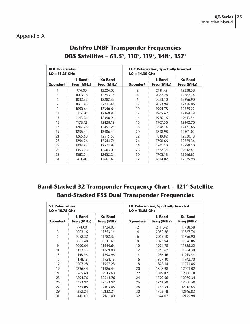
Appendix A
DishPro LNBF Transponder Frequencies DBS Satellites – 61.5°, 110°, 119°, 148°, 157°
RHC PolarizationLO = 11.25 GHz
L-Band Ku-BandXponder# Freq (MHz) Freq (MHz)
1 974.00 12224.00 3 1003.16 12253.16 5 1032.32 12282.32 7 1061.48 12311.48 9 1090.64 12340.64 11 1119.80 12369.80 13 1148.96 12398.96 15 1178.12 12428.12 17 1207.28 12457.28 19 1236.44 12486.44 21 1265.60 12515.60 23 1294.76 12544.76 25 1323.92 12573.92 27 1353.08 12603.08 29 1382.24 12632.24 31 1411.40 12661.40
LHC Polarization, Spectrally InvertedLO = 14.35 GHz
L-Band Ku-BandXponder# Freq (MHz) Freq (MHz)
2 2111.42 12238.58 4 2082.26 12267.74 6 2053.10 12296.90 8 2023.94 12326.06 10 1994.78 12355.22 12 1965.62 12384.38 14 1936.46 12413.54 16 1907.30 12442.70 18 1878.14 12471.86 20 1848.98 12501.02 22 1819.82 12530.18 24 1790.66 12559.34 26 1761.50 12588.50 28 1732.34 12617.66 30 1703.18 12646.82 32 1674.02 12675.98
L-Band Ku-BandXponder# Freq (MHz) Freq (MHz)
1 974.00 12224.00 3 1003.16 12253.16 5 1032.32 12282.32 7 1061.48 12311.48 9 1090.64 12340.64 11 1119.80 12369.80 13 1148.96 12398.96 15 1178.12 12428.12 17 1207.28 12457.28 19 1236.44 12486.44 21 1265.60 12515.60 23 1294.76 12544.76 25 1323.92 12573.92 27 1353.08 12603.08 29 1382.24 12632.24 31 1411.40 12661.40
L-Band Ku-BandXponder# Freq (MHz) Freq (MHz)
2 2111.42 12238.58 4 2082.26 12267.74 6 2053.10 12296.90 8 2023.94 12326.06 10 1994.78 12355.22 12 1965.62 12384.38 14 1936.46 12413.54 16 1907.30 12442.70 18 1878.14 12471.86 20 1848.98 12501.02 22 1819.82 12530.18 24 1790.66 12559.34 26 1761.50 12588.50 28 1732.34 12617.66 30 1703.18 12646.82 32 1674.02 12675.98
L-Band Ku-BandXponder# Freq (MHz) Freq (MHz)
2 2111.42 12238.58 4 2082.26 12267.74 6 2053.10 12296.90 8 2023.94 12326.06 10 1994.78 12355.22 12 1965.62 12384.38 14 1936.46 12413.54 16 1907.30 12442.70 18 1878.14 12471.86 20 1848.98 12501.02 22 1819.82 12530.18 24 1790.66 12559.34 26 1761.50 12588.50 28 1732.34 12617.66 30 1703.18 12646.82 32 1674.02 12675.98
Band-Stacked 32 Transponder Frequency Chart – 121° SatelliteBand-Stacked FSS Dual Transponder Frequencies
VL PolarizationLO = 10.75 GHz
L-Band Ku-BandXponder# Freq (MHz) Freq (MHz)
1 974.00 11724.00 3 1003.16 11753.16 5 1032.32 11782.32 7 1061.48 11811.48 9 1090.64 11840.64 11 1119.80 11869.80 13 1148.96 11898.96 15 1178.12 11928.12 17 1207.28 11957.28 19 1236.44 11986.44 21 1265.60 12015.60 23 1294.76 12044.76 25 1323.92 12073.92 27 1353.08 12103.08 29 1382.24 12132.24 31 1411.40 12161.40
HL Polarization, Spectrally InvertedLO = 13.85 GHz
L-Band Ku-BandXponder# Freq (MHz) Freq (MHz)
2 2111.42 11738.58 4 2082.26 11767.74 6 2053.10 11796.90 8 2023.94 11826.06 10 1994.78 11855.22 12 1965.62 11884.38 14 1936.46 11913.54 16 1907.30 11942.70 18 1878.14 11971.86 20 1848.98 12001.02 22 1819.82 12030.18 24 1790.66 12059.34 26 1761.50 12088.50 28 1732.34 12117.66 30 1703.18 12146.82 32 1674.02 12175.98
L-Band Ku-BandXponder# Freq (MHz) Freq (MHz)
1 974.00 11724.00 3 1003.16 11753.16 5 1032.32 11782.32 7 1061.48 11811.48 9 1090.64 11840.64 11 1119.80 11869.80 13 1148.96 11898.96 15 1178.12 11928.12 17 1207.28 11957.28 19 1236.44 11986.44 21 1265.60 12015.60 23 1294.76 12044.76 25 1323.92 12073.92 27 1353.08 12103.08 29 1382.24 12132.24 31 1411.40 12161.40
L-Band Ku-BandXponder# Freq (MHz) Freq (MHz)
2 2111.42 11738.58 4 2082.26 11767.74 6 2053.10 11796.90 8 2023.94 11826.06 10 1994.78 11855.22 12 1965.62 11884.38 14 1936.46 11913.54 16 1907.30 11942.70 18 1878.14 11971.86 20 1848.98 12001.02 22 1819.82 12030.18 24 1790.66 12059.34 26 1761.50 12088.50 28 1732.34 12117.66 30 1703.18 12146.82 32 1674.02 12175.98
L-Band Ku-BandXponder# Freq (MHz) Freq (MHz)
2 2111.42 11738.58 4 2082.26 11767.74 6 2053.10 11796.90 8 2023.94 11826.06 10 1994.78 11855.22 12 1965.62 11884.38 14 1936.46 11913.54 16 1907.30 11942.70 18 1878.14 11971.86 20 1848.98 12001.02 22 1819.82 12030.18 24 1790.66 12059.34 26 1761.50 12088.50 28 1732.34 12117.66 30 1703.18 12146.82 32 1674.02 12175.98

26 QT-SeriesInstruction Manual
VL PolarizationLO = 10.75 GHz
L-Band Ku-BandXponder# Freq (MHz) Freq (MHz)
1 970.00 11720.00 3 1010.00 11760.00 5 1050.00 11780.00 7 1090.00 11840.00 9 1130.00 11880.00 11 1170.00 11920.00 13 1210.00 11960.00 15 1250.00 12000.00 17 1290.00 12040.00 19 1330.00 12080.00 21 1370.00 12120.00 23 1410.00 12160.00
HL Polarization, Spectrally InvertedLO = 13.85 GHz
L-Band Ku-BandXponder# Freq (MHz) Freq (MHz)
2 2110.00 11740.00 4 2070.00 11780.00 6 2030.00 11820.00 8 1990.00 11860.00 10 1950.00 11900.00 12 1910.00 11940.00 14 1870.00 11980.00 16 1830.00 12020.00 18 1790.00 12060.00 20 1750.00 12100.00 22 1710.00 12140.00 24 1670.00 12180.00
L-Band Ku-BandXponder# Freq (MHz) Freq (MHz)
1 970.00 11720.00 3 1010.00 11760.00 5 1050.00 11780.00 7 1090.00 11840.00 9 1130.00 11880.00 11 1170.00 11920.00 13 1210.00 11960.00 15 1250.00 12000.00 17 1290.00 12040.00 19 1330.00 12080.00 21 1370.00 12120.00 23 1410.00 12160.00
L-Band Ku-BandXponder# Freq (MHz) Freq (MHz)
1 970.00 11720.00 3 1010.00 11760.00 5 1050.00 11780.00 7 1090.00 11840.00 9 1130.00 11880.00 11 1170.00 11920.00 13 1210.00 11960.00 15 1250.00 12000.00 17 1290.00 12040.00 19 1330.00 12080.00 21 1370.00 12120.00 23 1410.00 12160.00
L-Band Ku-BandXponder# Freq (MHz) Freq (MHz)
2 2110.00 11740.00 4 2070.00 11780.00 6 2030.00 11820.00 8 1990.00 11860.00 10 1950.00 11900.00 12 1910.00 11940.00 14 1870.00 11980.00 16 1830.00 12020.00 18 1790.00 12060.00 20 1750.00 12100.00 22 1710.00 12140.00 24 1670.00 12180.00
L-Band Ku-BandXponder# Freq (MHz) Freq (MHz)
2 2110.00 11740.00 4 2070.00 11780.00 6 2030.00 11820.00 8 1990.00 11860.00 10 1950.00 11900.00 12 1910.00 11940.00 14 1870.00 11980.00 16 1830.00 12020.00 18 1790.00 12060.00 20 1750.00 12100.00 22 1710.00 12140.00 24 1670.00 12180.00
Appendix A
Band-Stacked 24 Transponder Frequency Chart – 105° SatelliteBand-Stacked FSS Dual Transponder Frequencies
27QT-Series Instruction Manual
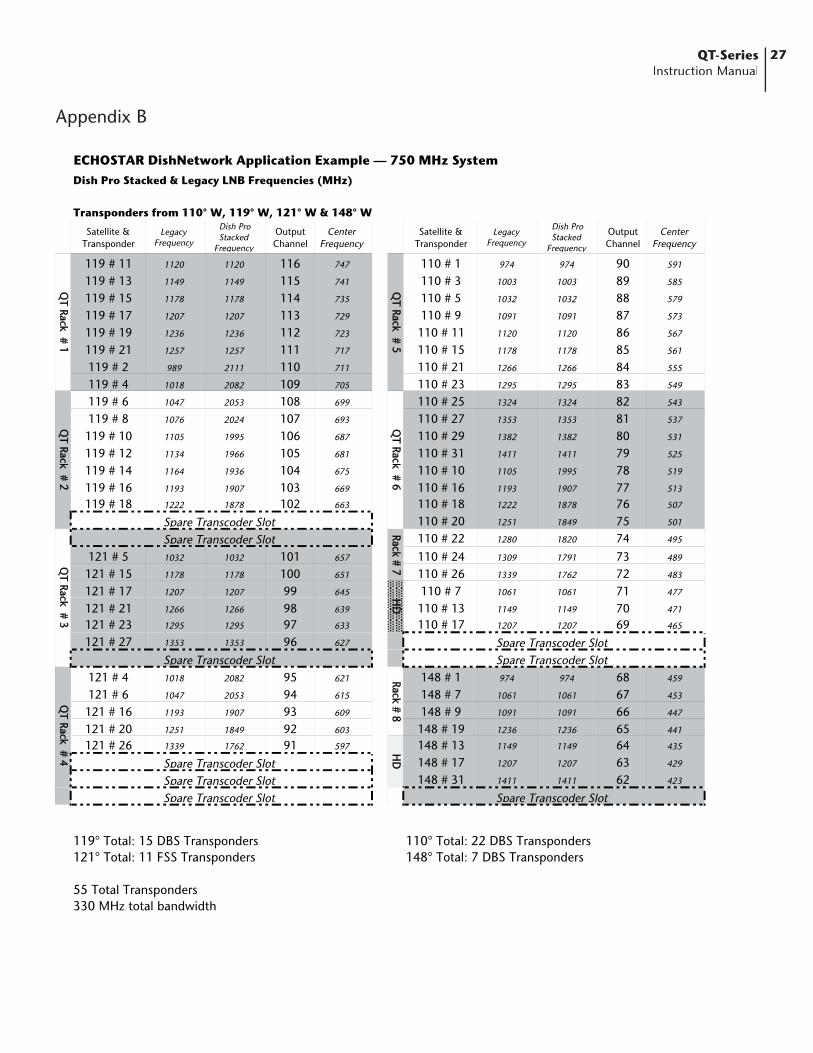
Appendix B
ECHOSTAR DishNetwork Application Example — 750 MHz SystemDish Pro Stacked & Legacy LNB Frequencies (MHz)
Transponders from 110° W, 119° W, 121° W & 148° W
Satellite & Transponder
LegacyFrequency
Dish Pro Stacked
Frequency
OutputChannel
CenterFrequency
Satellite & Transponder
LegacyFrequency
Dish Pro Stacked
Frequency
OutputChannel
CenterFrequency
119 # 11 1120 1120 116 747 110 # 1 974 974 90 591
119 # 13 1149 1149 115 741 110 # 3 1003 1003 89 585
119 # 15 1178 1178 114 735 110 # 5 1032 1032 88 579
119 # 17 1207 1207 113 729 110 # 9 1091 1091 87 573
119 # 19 1236 1236 112 723 110 # 11 1120 1120 86 567
119 # 21 1257 1257 111 717 110 # 15 1178 1178 85 561
119 # 2 989 2111 110 711 110 # 21 1266 1266 84 555
119 # 4 1018 2082 109 705 110 # 23 1295 1295 83 549
119 # 6 1047 2053 108 699 110 # 25 1324 1324 82 543
119 # 8 1076 2024 107 693 110 # 27 1353 1353 81 537
119 # 10 1105 1995 106 687 110 # 29 1382 1382 80 531
119 # 12 1134 1966 105 681 110 # 31 1411 1411 79 525
119 # 14 1164 1936 104 675 110 # 10 1105 1995 78 519
119 # 16 1193 1907 103 669 110 # 16 1193 1907 77 513
119 # 18 1222 1878 102 663 110 # 18 1222 1878 76 507
110 # 20 1251 1849 75 501
110 # 22 1280 1820 74 495
121 # 5 1032 1032 101 657 110 # 24 1309 1791 73 489
121 # 15 1178 1178 100 651 110 # 26 1339 1762 72 483
121 # 17 1207 1207 99 645 110 # 7 1061 1061 71 477
121 # 21 1266 1266 98 639 110 # 13 1149 1149 70 471
121 # 23 1295 1295 97 633 110 # 17 1207 1207 69 465
121 # 27 1353 1353 96 627
121 # 4 1018 2082 95 621 148 # 1 974 974 68 459
121 # 6 1047 2053 94 615 148 # 7 1061 1061 67 453
121 # 16 1193 1907 93 609 148 # 9 1091 1091 66 447
121 # 20 1251 1849 92 603 148 # 19 1236 1236 65 441
121 # 26 1339 1762 91 597 148 # 13 1149 1149 64 435
148 # 17 1207 1207 63 429
148 # 31 1411 1411 62 423
119° Total: 15 DBS Transponders 110° Total: 22 DBS Transponders121° Total: 11 FSS Transponders 148° Total: 7 DBS Transponders
55 Total Transponders330 MHz total bandwidth
QT
Rack#
4Q
TRack
#3
QT
Rack#
5Q
TRack
#6
QT
Rack#
1Q
TRack
#2
HD
HD
Rack#
7
Spare Transcoder SlotSpare Transcoder Slot
Spare Transcoder Slot
Spare Transcoder SlotSpare Transcoder SlotSpare Transcoder Slot
Spare Transcoder SlotSpare Transcoder Slot
Spare Transcoder Slot
Rack#
8

28 QT-SeriesInstruction Manual
Appendix CBlock Diagram
64 QTM Transcoder Rack Assembly
QTRA-8 RF Out 27 dBmV
QTRA-8 RF Out 27 dBmV
QTSPS Stand-byPower
AC IN
QTRA-8 RF Out 27 dBmV
QTRA-8 RF Out 27 dBmV
QTSPS Stand-byPower
AC IN
QTRA-8 RF Out 27 dBmV
QTRA-8 RF Out 27 dBmV
QTSPS Stand-byPower
AC IN
QTRA-8 RF Out 27 dBmV
QTRA-8 RF Out 27 dBmV
QTSPS Stand-byPower
AC IN
GAINCONTROL
SLOPE CONTROL
HDA-8-860-20HEADEND DISTRIBUTIONAMPLIFIER
45 dBmV64 Channel
(384 MHz of QAM)
Covering Channel (2-135)(57-861 MHz)
Block DiagramQTRA-8 Detailed
QTPCMPOWER OUTData OUT/IN
QPSK-INPower/Data
QPSK-INPower/Data
QPSK-INPower/Data
QPSK-INPower/Data
QPSK-INPower/Data
QPSK-INPower/Data
QPSK-INPower/Data
QPSK-INPower/Data
QTM #8
QTM #7
QTM #6
QTM #5
QTM #4
QTM #3
QTM #2
RF Out 40 dBmV
RF Out 40 dBmV
RF Out 40 dBmV
RF Out 40 dBmV
RF Out 40 dBmV
RF Out 40 dBmV
RF Out 40 dBmV
QTM #1RF Out 40 dBmV
QTRFC8-WAY RF COMBINER
8 Channel QAM
RF Out
Combined27 dBmV/Ch.
Remote Control INLoop OUT
-65, -25 dBm
950-2150 MHzQPSK IN
AC IN Stand-by Power
QTRFSL-BAND8-WAYSPLITTER

One Jake Brown RoadOld Bridge, NJ 08857-1000 USA
(800) 523-6049 • (732) 679-4000 • FAX: (732) 679-4353www.blondertongue.com
Limited WarrantyBlonder Tongue Laboratories, Inc. (BT) will at its sole option, either repair or replace (with a new or factory reconditioned product, as BT may determine) any product manufactured by BT which proves to be defective in materials or workmanship or fails to meet the specifications which are in effect on the date of shipment or such other specifications as may have been expressly agreed upon in writing (i) for a period of one (1) year from the date of original purchase (or such shorter period of time as may be set forth in the license agreement specific to the particular software being licensed), with respect to iCentral™ (hardware and software) and all other software products (including embedded software) licensed from BT, (ii) ) for a period of one (1) year from the date of original purchase, with respect to all MegaPort products and fiber optics receivers, transmitters, couplers and integrated receivers/distribution amplifiers (including TRAILBLAZER™, RETRO-LINX™ and TWIN STAR™ products) as well as for VideoCipher® & DigiCipher® satellite receivers, and (iii) for a period of three (3) years from the date of original purchase,with respect to all other BT products. Notwithstanding the foregoing, in some cases, the warranty on certain proprietary sub-assembly modules manufactured by third-party vendors and contained in BT products and on certain private–label products manufactured by third-parties for resale by BT are of shorter duration or otherwise more limited than the standard BT limited warranty. In such cases, BT’s warranty with respect to such third-party proprietary sub-assembly modules and private-label products will be limited to the duration and other terms of such third party vendor’s warranty. In addition, certain products, that are not manufactured but are resold by BT, carry the original OEM warranty for that product. The limited warranty set forth in this paragraph does apply to any product sold by BT, which at the time of sale constituted a Deal Den product, unless specified. Factory reconditioned or refurbished product warranty maybe of shorter duration as specified.
BT will at its sole option, either repair or replace (with a new or factory reconditioned product, as BT may determine) any product sold by BT which at the time of sale constituted a Refurbished item (“Refurbished Product”), which proves to be defective in materials or workmanship or fails to meet the specifications which are in effect on the date of shipment or such other specifications as may have been expressly agreed upon in writing, for a period of ninety (90) days from the date of original purchase, unless specified. Notwithstanding the foregoing, in some cases, the warranty on third party software and on certain proprietary sub-assembly modules manufactured by third-party vendors and contained in BT products and on certain private–label products manufactured by third-parties for resale by BT are of shorter duration or otherwise more limited than the BT limited warranty for Refurbished Products. In such cases, BT’s warranty for Refurbished Products constituting such third party software, third-party proprietary sub-assembly modules and private-label products will be limited to the duration and other terms of such third-party vendor’s warranty. In addition, notwithstanding the foregoing, (i) certain Refurbished Products that are not manufactured (but are resold) by BT, carry the original OEM warranty for such products, which may be longer or shorter than the BT limited warranty for Refurbished Products. All sales of Refurbished Products are final.
To obtain service under this warranty, the defective product, together with a copy of the sales receipt or other satisfactory proof of purchase and a brief description of the defect, must be shipped freight prepaid to: Blonder Tongue Laboratories, Inc., One Jake Brown Road, Old Bridge, New Jersey 08857.
This warranty does not cover damage resulting from (i) use or installation other than in strict accordance with manufacturer’s written instructions, (ii) disassembly or repair by someone other than the manufacturer or a manufacturer-authorized repair center, (iii) misuse, misapplication or abuse, (iv) alteration, (v) lack of reasonable care or (vi) wind, ice, snow, rain, lightning, or any other weather conditions or acts of God.
OTHER THAN THE WARRANTIES SET FORTH ABOVE, BT MAKES NO OTHER WARRANTIES OR REPRESENTATIONS OF ANY KIND, EXPRESS OR IMPLIED, AS TO THE CONDITION, DESCRIPTION, FITNESS FOR A PARTICULAR PURPOSE, MERCHANTABILITY OR AS TO ANY OTHER MATTER, AND SUCH WARRANTIES SUPERSEDE ANY ORAL OR WRITTEN WARRANTIES OR REPRESENTATIONS MADE OR IMPLIED BY BT OR BY ANY OF BT’S EMPLOYEES OR REPRESENTATIVES, OR IN ANY OF BT’S BROCHURES, MANUALS, CATALOGS, LITERATURE OR OTHER MATERIALS. IN ALL CASES, BUYER’S SOLE AND EXCLUSIVE REMEDY AND BT’S SOLE OBLIGATION FOR ANY BREACH OF THE WARRANTIES CONTAINED HEREIN SHALL BE LIMITED TO THE REPAIR OR REPLACEMENT OF THE DEFECTIVE PRODUCT F.O.B. SHIPPING POINT, AS BT IN ITS SOLE DISCRETION SHALL DETERMINE. BT SHALL IN NO EVENT AND UNDER NO CIRCUMSTANCES BE LIABLE OR RESPONSIBLE FOR ANY CONSEQUENTIAL, INDIRECT, INCIDENTAL, PUNITIVE, DIRECT OR SPECIAL DAMAGES BASED UPON BREACH OF WARRANTY, BREACH OF CONTRACT, NEGLIGENCE, STRICT TORT LIABILITY OR OTHERWISE OR ANY OTHER LEGAL THEORY ARISING DIRECTLY OR INDIRECTLY FROM THE SALE, USE, INSTALLATION OR FAILURE OF ANY PRODUCT ACQUIRED BY BUYER FROM BT.
All claims for shortages, defects and non-conforming goods must be made by Buyer in writing within five (5) days of receipt of merchandise, which writing shall state with particularity all material facts, concerning the claim then known to Buyer. Upon any such complaint, Buyer shall hold the goods complained of intact and duly protected, for a period of up to sixty (60) days. Upon the request of BT, Buyer shall ship such allegedly nonconforming or defective goods, freight prepaid to BT for examination by BT’s inspection department and verification of the defect. BT, at its option, will either repair, replace or issue a credit for products determined to be defective. BT’s liability and responsibility for defective products is specifically limited to the defective item or to credit towards the original billing. All such replacements by BT shall be made free of charge f.o.b. the delivery point called for in the original order. Products for which replacement has been made under the provisions of this clause shall become the property of BT. Under no circumstances are products to be returned to BT without BT’s prior written authorization. BT reserves the right to scrap any unauthorized returns on a no-credit basis. Any actions for breach of this contract must be commenced by Buyer within thirteen (13) months after the cause of action has accrued. A copy of BT’s standard terms and conditions of sale, including the limited warranty, is available from BT upon request. Copies of the limited warranties covering third-party proprietary sub-assembly modules and privatelabel products manufactured by third-parties are also available from BT on request. VideoCipher® & DigiCipher® are registered trademarks of Motorola Corp.