qrs grand stop rail installation guide product introduction. stop rail install v1.1(56064i...qrs...
TRANSCRIPT
QRS Grand stop rail installation guideProduct introduction.
The QRS hammer stop system has been designed as a reliable, easy to install and use solutionfor silencing the acoustic piano by preventing the hammers from hitting the strings. Thisfeature is very useful when use in conjunction with the QRS PNOscanII MIDI system and MIDIsound module, providing silent practice mode where the pianist listens to their performance wearing headphones. Another innovative use is digital mode which allows the user to turn the piano into other instruments such as an organ, string section or a variety of other sounds.
The hammer stop system has been carefully engineered to allow precise blocking of the hammer at the point of action travel known as let-off or escapement. The system employees specially formulated rubber as a contact surface which provides an accurate and consistent braking point allowing the hammers to be safely stop with minimal noise. Unlike other systems that use felt or open cell rubbers, the QRS system will remain stable for many hours of use and the overall accuracy will remain consistent over the entire keyboard range.
There are basically two types of piano construction which you will encounter with grand pianos.There is a standard design and a focus beam design. The QRS Hammer Stop system has beendesigned to reliably retrofit into either type without compromising the structure of the piano.
Although the system should fit into most of the piano models without requiring measures beyond this guide however you may encounter a piano that requires slight modifications such as grinding a low spot in a plate casting or you may find the need to cut excess material off the top edge of a bumper rail for instance. In any case if modifications are required to make the system function properly, the mods should be minor.

QRS Grand Hammer stop installation guidePage 2
Before beginning the installation process you will need to determine if minimum space requirements are met with your particular piano brand / model.
Piano compatibility with the Stop rail system,
The most common area that can cause difficulty or prevent the Hammer stop from fitting into a particular piano is the space starting at the bottom of the pin block up to the low point of plate. The amount of available space in this area varies widely among piano models.
The QRS Hammer stop system was designed from the ground up to be as flexible as possible, allowing the system to be installed into most models of grand pianos. The size of key Hammer stop components is minimized to allow the components to be squeezed into very close areas while still maintaining excellent strength characteristics.
Take a look at FIG A. below. Points A and B show the represent the vertical space needed for the hammer stop rail and the points between C and D represents the front to back space required.
The minimum distance between point A and B must not be less than 3/4" and a minimum of 1" between C and D with the hammer in the up position. The space in the A/B area must be great enough to allow the hammer stop rail to remain flush or above the bottom of the pin block so that the action / hammer assembly clears the shaft / bumper rail when removing it.
Cast plateString plane
Pin block
Key bed
Belly timberHammerHammer stop shaft / bumper
SoundboardB
AC D
FIG A

QRS Grand Hammer stop installation guide
Page 3Taking measurements for component placement.
Locating the stop rail bearings requires only a few simple measurements. Using care to acquire accurate measurements and transfer them inside the piano case will make your installation reasonably easy and successful. Please refer to FIG C below relative to taking required measurements. These 2 measurements represent the center axis of the hammer stop rail main shaft.
Before moving the action / key frame from it's correct position, strike a pencil line on the key bed at each end, front edge of the key frame. See FIG B.If the piano is a focus beam type, place a 3rd pencil mark along thesame edge directly in line with the 1st key break at the bass section.
FIG B.
Measure between these points and subtract 1 inch. This willbe the front / back positionfor the center of the shaft.
Measure from bedding point of key frame to top of hammer at rest position.
FIG C
Depth measurement
Height measurement
QRS Grand Hammer stop installation guidePage 4Layout for component placement.
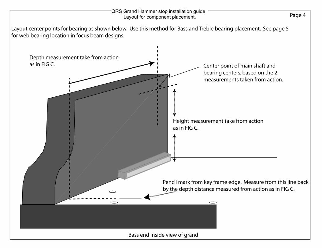
Pencil mark from key frame edge. Measure from this line backby the depth distance measured from action as in FIG C.
Depth measurement take from actionas in FIG C.
Height measurement take from actionas in FIG C.
Center point of main shaft and bearing centers, based on the 2measurements taken from action.
Bass end inside view of grand
Layout center points for bearing as shown below. Use this method for Bass and Treble bearing placement. See page 5for web bearing location in focus beam designs.

QRS Grand Hammer stop installation guidePage 8Component placement
Assemble the main bearing components. Be certain to use the correct screw supplied to hold the bearing seat onto the bearing mount. Tighten the screw 1/8 - 1/4 turn past head to plastic contact.
Locate the main bearings to the piano case. Place a pencil through the bearinghole with the point of the pencil centered on the previously marked center lineswhile pressing the bearing mount firmly to the sidewall and trace the two slotsonto the wood. Once the slots are marked use an 1/8" drill to pilot drill at the midpoint of the slot area.
Fasten the bearing assemblies with the #6 x 5/8" pan head screws. At this pointthe bearing should be very close to the correct location although there is plentyof up / down and left / right adjustment should you need to adjust the position.
Use a pencil to hang the bearing mount in it's proper location relative to linesdrawen on sidewall of piano.
Using another pencil, trace the 2 slots.
USE CARE NOT TO OVER_TIGHTEN! DAMAGE TO PLASTIC CAN OCCUR!!

QRS Grand Hammer stop installation guide
Page 5Section 2Focus beam bearing location
Referencing the pencil mark you made on the keybed previously, measure from the mark in toward the cast flange to the front edge of a combination square as shown in FIG D. While the square is in place at the proper depth make a vertical line on the flange. Also place a horizontal line at the same height used to place the bass and treble end bearings.
These intersecting lines indicate the center point of the main shaft and bearings. See FIG D.
Use one of the web bearings as a template, holding the web bearing against the flange at about 30 to 40 degrees from vertical and the bottom of the bearing pointing forward, center the bearing hole over the center lines and trace the 2 slots onto the casting. The dottedlines show where the bearing was being held to mark the slot area.
FIG D
FIG E
It is possible that certain piano models may require the bearings be oriented at a different angle than shown here.

QRS Grand Hammer stop installation guidePage 6For focus beam bearing location only
With the 2 bearing slots marked on the flange, use a center punch to carefully dimple 2 places in the center of the slot marks to allow accurate drill indexing.
Do not drill the actual bearing center location. The shaft / bearing does notextend into or through the web. Fig E.
Proceed to drill the two 11/64" holes at the 2 center punched locations. It is veryimportant that the two holes are drilled straight and level. The holes need to bedrilled clear through the flange. The 2 holes will be used to mount both bearings to the flange. Fig F
It is a good idea to cover the components in the drilling area with plastic or polyfoam to avoid getting metal chips into the action parts.
Using a true and square wood block cut to the height of the drill bit can aid in keeping the drill bit level and straight. Set the block on the key bed in front of the bit and reference the edge of the block to the drill bit by sight. A combinationsquare will also do the job.
FIG E
FIG F

Depending on the particular piano you are working on the cast flange might be adifferent size and shape requiring a different position. Mount the bearing at some angle which will allow you to adjust the bearing / shaft both forward / backward as well as up / down should you need to fine tune the placement.
The flange wall can vary from model to model and can have some tapper from topto bottom. Normally the tapper is minimal and the bearings can be applied directlyto the flange. If the tapper is severe you may need to use a shim to compensate.
QRS Grand Hammer stop installation guidePage 7Focus beam type component assembly
Assemble the web bearings. Use care when tightening the bearing retainers. The #2screws are threading into plastic and only need to be tightened to the point where the screw head touches the plastic surfaces. There is no significant force on the retainers and only serve to prevent the bearing from possibly walking on the shaft during transport.
Once the two web bearings are assembled they can be mounted onto the cast web of the piano. Use two elliptic washers on the screw head side. The flats of the nuts will need to be aligned with the slot relief so that the nuts set down into the flange slots.
With flanges aligned to the layout lines and secured with the bolts, washers and nutscut the extra bolt length off flush with the nuts using a rotary cut-off tool or fine toothhacksaw blade. Once the bolts are cut, re-tighten the nuts.
Tighten the screws as tight as possible using a standard sized #1 screw driver. Cracks in the bearing seat could occur from over tightening if you attempt to tighten the nuts with a socket or wrench. It's OK to hold the nuts with pliers while tightening.

QRS Grand Hammer stop installation guidePage 2
Take a measurement of the key frame rest block thickness. You will use this measurement to determine the overall shaft length.As you find the optimum position for the shaft / bumper assembly relative to the hammer shanks you will need to determine the specific shaft overhang distance and shaft length. The mainshaft is longer than needed to provide flexibility in alignment and will need cut at both ends. When cutting the steel shaft it is recommended that you cut a bit long and grind or file to exact length
Block width
Once you have the shaft / bumper assembly aligned with the hammer shanks and the shaft ends marked for the proper overhang, compare the distance between your shaft end marks and thedistance between the inside walls of the piano case. The total shaft length should be within 1/8" of the total width inside piano case. Proceed to cut the steel shaft. Bevel ends of shaft after cutting.
The bass end of the shaft must extend past the key frame edge by the width of the key frame rest block minus 1/16".
Sha
ft ov
er h
ang
= fra
me
edge
dis
tanc
e pl
us b
lock
wid
th.
Ham
mer
bum
per
cent
ers
Bas
s
Ham
mer
bum
per
cent
ers
Teno
r
Ham
mer
bum
per
cent
ers
Mid
Tre
ble
Ham
mer
bum
per
cent
ers
Treb
le
Sha
ft ov
er h
ang
= ce
nter
of h
amm
er #
88 to
pia
nosi
de w
all.
To determine shaft overhang on the treble end use hammer shank #88 as a reference point and measure across the shaft to a distance equal to the distance between damper wire #88 and the side wall of the piano case where the bearing mount is attached.
Shaft / bumper layout
QRS Grand Hammer stop installation guidePage 9Locating the main shaft and bumper rails relative to hammers.
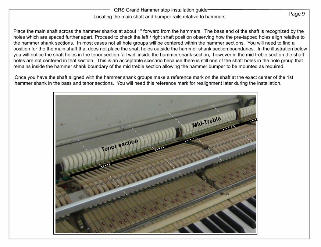
Place the main shaft across the hammer shanks at about 1" forward from the hammers. The bass end of the shaft is recognized by the holes which are spaced further apart. Proceed to check the left / right shaft position observing how the pre-tapped holes align relative to the hammer shank sections. In most cases not all hole groups will be centered within the hammer sections. You will need to find a position for the the main shaft that does not place the shaft holes outside the hammer shank section boundaries. In the illustration below you will notice the shaft holes in the tenor section fall well inside the hammer shank section, however in the mid treble section the shaft holes are not centered in that section. This is an acceptable scenario because there is still one of the shaft holes in the hole group that remains inside the hammer shank boundary of the mid treble section allowing the hammer bumper to be mounted as required.
Tenor section
Mid-Treble
Once you have the shaft aligned with the hammer shank groups make a reference mark on the shaft at the exact center of the 1st hammer shank in the bass and tenor sections. You will need this reference mark for realignment later during the installation.

QRS Grand Hammer stop installation guidePage 9BLocating the main shaft and bumper rails
When installing into a focus beam model piano the shaft will be cut into two sections. One lenght will be for the bass section and the other lenght will cover the remaining hammer sections. Follow the basic layout instructions of the non-focus beam page except you will focus attention primarly to hammer shank / shaft hole alignment of the bass section first.
Focus beam type
Depending on the piano model, you may find that laying out the bass shaft and cutting it to length prior to laying out the treble end will make alignment of the tenor / treble section easier. This also allows the option of flipping the treble shaft section end for end as an additional option which can work well for shaft hole alignment in some cases. In all case the bass shaft assembly should always remain at the bass end of action.
Additionally take measurements from the last damper wire in the bass section to the cast flange where the web bearing is mounted as well as the first damper wire of the tenor section to the treble side of the cast flange. You will then transfer those measurements to the main shaft using the corresponding hammer shanks and marking the shaft. This will be the shaft overhang needed to engage the web bearings. fig M and fig N.
FIG M
FIG N.
Cut shaft here.

QRS Grand Hammer stop installation guidePage 10Preparing main shaft and bumper rails
At this point you have located and aligned the threaded main shaft holes with the hammer shank sections and made reference marks on the shaft at note #1 and at the location of the 1st hammer shank of the tenor section. You will now place the 4 hammer shank bumpers across the shaft and align the slots of the bumpers with the appropriate shaft holes.Place a mark at the end of each bumper so that there is 1/4" of the aluminum overhanging each end of the hammer shank groups. Cut each of the bumpers at the marks and file or sand rough edges. You may find that during the final assembly it is necessary to file someadditional length from some bumpers but it's best to start slightly longer than actually needed and trim to fit.
Be certain slots in bumper are aligned withthe holes in the shaft before marking bumpers.
Mark ends of bumper at 1/4" beyond hammer shank.
Mark ends of bumper at 1/4" beyond hammer shank.

QRS Grand Hammer stop installation guideFor focus beam bearing location only
Once bumpers are cut to lenght apply the self-adheasive felt strips to the inside surfaceof each bumper. Keep the felt centered between the bend and the edge. Apply the feltin 3 sections cutting the felt so that it comes up to the edge of the slots entirely withoutover-hanging the slot.
Apply the rubber stripping to the outside surface of the narrow edge of the tenor, mid-treble and treble bumpers. Do not apply the rubber to the bass bumper at this point.There is one small section of single string notes at the bass end of the action whichuse a thicker rubber strip as included in the kit. Should the shaft / bumper assemblyshift slightly to one side or the other during the final installation you can compensateat that time.
Prepare the main shaft by sliding on a bearing at 4 points along the steel shaft. Install one bearing bewteen each bumper space which is at same location as the action break points.Please note that these bearings are specially designed to maintain there position on the steel main shaft during use and are very snug. DO NOT LUBRICATE AND DO NOT USE TOOLS TO GRIP THE BEARING!
Get the bearing started squarely over the end of the shaft and then tap the bearing with asoft face hammer or small block of wood to get it fully onto the shaft. Use care to tap on theface of the bearing only and not to hit it on the edges which will damage it. Once the bearing is fully on the shaft it should slide along the shaft with reasonable hand force.If you are working with a shaft that has been cut to lenght, be sure to put a smooth bevelon the cut ends to ease bearing istallation.
Hammer bumper locations
Bearing
It is critical to proper function of the stop rail system that the rubber be applied streightand without bumps or waves.

QRS Grand Hammer stop installation guideFor focus beam bearing location only
Once all shaft components are installed you can install the bumpers which are now cutto length. The bumpers are secured with two flat washers and two 4-40 cap screws.
At this point just lightly snug the screws enough to hold the bumpers at the mid point oftheir adjustment range. Don not fully tighten at this point.
With a focus beam type piano you will have additional components at the shaft endson each side of the cast flange.
There are 2 rail links that must be placed onto the shaft before the bearings. Whenplacing the rail links take notice of the 10 degree rotation of the inner square hole inrelation to the rest of the part. This offset is intended to position the link arm in aslight downward projection which helps clear the cast flange when the shaft rotates.
On the bass end of the main shaft install the actuator lever first. The lever has a star shaped hole to allow fine adjustment of the lever orientation. This is important because the lever needs to be slightly forward of center so the control cable can push and pull properly. The normal orientation is such that when the shaft is positioned with the holes facing down the lever will be offset 1 step upward. Note that the as with the other rail components thelever is designed to press onto the shaft with significant resistance. Again, do not lubricate!
BASS TREBLEFIG E
FIG F
FIG G
FIG H
Continue by installing a lock collar on each end of the shaft and then the bearings.
Shaft holes down
Use the thin bearings for a focus beam installation at the cast flange location.

QRS Grand Hammer stop installation guideFinal steps of installation
Focus beam link assembly
At this stage of the installation the main bearings and flange bearings have been installed. Continue the installation by installingthe hardware that couples the rail links together. The hardware included allows for a couple options, again depending on yourspecific model of piano.If the cast flange which hangs down from the plate is short and does not extend forward to far you can use the 1/4" aluminum tubeand 4-40 all-thread stud. Simply cut the tube to the needed length, insert the stud through the links and tubing and fasten securelywith 2 washers and nuts.
If the cast web extends downward and or outward too far to use the tube, use the saddle which allows the links to be joined aroundthe cast flange. As long as there is no interference with the action the saddle can be used in any case.
CouplerTube
Stud, washers and nuts.
Option 1Option 2
Cast flange.

QRS Grand Hammer stop installation guideFor non - focus beam installation
With all of the components prepped and the bearing mounts installed into the piano youcan now continue by installing the main shaft / bumper assemblies.
In a standard, non-focus beam type piano, place the main bearing seats onto the bearingsat both the bass and treble ends of the main shaft assembly. fig J.
Place the shaft / bumper assembly into the piano case and set the bearing seats ontothe main bearing mounts. Install a #4 screw and washer through the slot of the bearingseat and turn screw in until the head touches the plastic. It is assumed that the bearingis reasonably close to the correct location when you installed the mount. There is oneadditional hole on each end of the bearing mount as well as the slot in the seat toallow compensation for misalignment if needed. fig K.
At this point check if the shaft is cut to the correct length. The shaft needs just lessthan 1/8" of left to right moment for unrestricted rotation of assembly. If the shaft isrubbing against the piano side walls as you place it in position, grind the requiredamount to gain the side to side clearance.
Once both ends of the shaft are secured to the bearing mounts check that the assembly rotates freely and that the bumpers can be rotated 90 degrees from a vertical position. When the rubber faces toward the key bed the system is engaged and when the rubber faces forward the system is disengaged. The system must be disengaged when removing the action.
If you find that one of the bumpers is hitting the plate or other piano structure you may needto lower the assembly using the adjustment slots in the main bearing mounts. In all cases the shaft / bumper assembly must not be lower than the tip of the hammers at rest. This assures that the hammers will not catch on the main shaft when sliding the action in or out.
If the bumpers are hitting the pin block when you rotate the shaft toward the disenagaed position you can lower the bumpers using the adjustment slots. In most cases the bumpers will be extending below the shaft 1/8" to 1/4" in their final adjusted position. fig L.Measure the top of the hammer shank at the point of escapement or let off at one inch forward of the hammers, to the lowest bedding point of the key frame. This distance is very close to the final distance needed between the bumper rubber and the key bed.
FIG J
FIG K
FIG L
Shaft
Bumper

QRS Grand Hammer stop installation guideFinal steps of installation
At this point you should have the shaft / bumper assembly installed and verified that theassembly rotates freely from vertical to 90 degrees horizontal.
You can now install the mid bearing mounting brackets and mid bearing mounts. You willnotice that the metal bearing mount brackets are built with an offset. When the bracket isinstalled correctly the offset places the bearing in the center of each action break and is also typically the center of the sostenuto bracket.
There should be a shaft bearing that you previously installed at each break, between bumpers. Attach the bearing seats to the shaft by sliding the opening of the seat over the shaft beside the bearing and then moving the seat over the bearing into position.
You will use 3 mid bearings in a non-focus beam type installation and 2 mid bearings in afocus beam type. With the mid bearing seat now engaged with the shaft bearing you canattach the mid bearing mount to the metal mount bracket. Before snugging the screws onon the mid bearing mount / bracket, position the bracket to the wood beam behind the damper wires. When positioning the bracket, find the position that imposes no stress on the main shaft which would cause binding. The mid bearings should only support the shaft assembly along it's natural path. While holding the bracket / bearing assembly in this position trace the entire slot of the bracket onto the wood.Remove the bracket / bearing mount and pre-drill 2 holes within the traced slot area. Keepthe screws about 1" apart and inside the slot area, allowing enough room to allow for vertical adjustment of the bracket. Fig O.
It is common to see the main belly timber with a tapper in which case you should shim underthe bottom screw of the bracket to prevent distorting the bracket when tightening the screws. Cutting a wedge of wood and drilling a hole for the screw to pass through makes an ideal shim, but a flat washer can also be used. Fig P.
Mid bearing mount
Wedge shim
FIG O
FIG P
FIG Q
The shaft assembly should be now installed with all support bearings in place. Recheck thethe shaft assembly for binding during rotation. If the shaft assembly does not rotate freelyyou need to readjust one or more of the mid bearings. Fig Q.
Bellytimber
QRS Grand Hammer stop installation guideFinal steps of installation
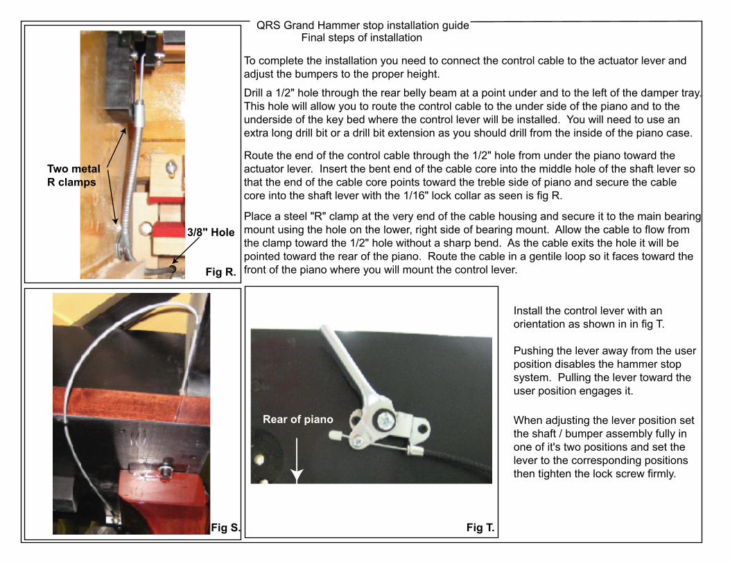
To complete the installation you need to connect the control cable to the actuator lever and adjust the bumpers to the proper height.
Drill a 1/2" hole through the rear belly beam at a point under and to the left of the damper tray.This hole will allow you to route the control cable to the under side of the piano and to the underside of the key bed where the control lever will be installed. You will need to use an extra long drill bit or a drill bit extension as you should drill from the inside of the piano case.
Route the end of the control cable through the 1/2" hole from under the piano toward theactuator lever. Insert the bent end of the cable core into the middle hole of the shaft lever so that the end of the cable core points toward the treble side of piano and secure the cable core into the shaft lever with the 1/16" lock collar as seen is fig R.
Place a steel "R" clamp at the very end of the cable housing and secure it to the main bearingmount using the hole on the lower, right side of bearing mount. Allow the cable to flow fromthe clamp toward the 1/2" hole without a sharp bend. As the cable exits the hole it will be pointed toward the rear of the piano. Route the cable in a gentile loop so it faces toward thefront of the piano where you will mount the control lever.Fig R.
Fig S.
3/8" Hole
Two metal R clamps
Rear of piano
Install the control lever with anorientation as shown in in fig T.
Pushing the lever away from the userposition disables the hammer stopsystem. Pulling the lever toward theuser position engages it.
Fig T.
When adjusting the lever position setthe shaft / bumper assembly fully in one of it's two positions and set thelever to the corresponding positionsthen tighten the lock screw firmly.

QRS Grand Hammer stop installation guideFinal steps of installation
The final steps in the installation involves setting each bumper to the correct height sothat the hammers contact the bumpers at exactly the right point to allow a natural feelof the keyboard.
If the measurements taken earlier in the install process are reasonably accurate you willneed to make just small adjustments to the height of the bumpers. The actual adjustment is done using the small cap head screws that hold the bumper to the shaft. At this point the cap screws should only be slightly snug and will not be fully tightened until the final adjustment is complete. It is critical to understand what the keyboard should feel like when the system is properlyadjusted. We will use the term "crunchy" to describe the feel of keys that require slightly toomuch force to send action to through escapement or let-off. This is the point at which the jack disengages from the knuckle. There is a very fine line between the bumper being too low or too high relative to where it contacts the hammer shanks. Too low and the keys become "crunchy", too high and you will hear the hammer bumping the strings. Whenthe system is adjusted correctly you can play the keys normally with good feel maintainedacross the keyboard. It is important to realize the intention of this system is to silence thepiano under normal playing conditions. At some point if a player is striking the keys withextreme force, some hammers may hit the string causing it to sound to some degree.
To make this fine adjustment of the bumper height easier, we suggest making somesimple height adjustment tools. It can be as simple some sticks that are a 1/2" shorterthan the distance between the key bed and the bottom of the bumper with a 1" flat headscrew threaded into the end. Adjust the screw until it just touches the bottom of the bumperwhen setting on the key bed. Use this as your starting point and then thread the screw inor out the same amount you want to move the bumper up or down.
Key bed
Adjust the screw up or down the same distance you wantto move the bumper.
You will find that normally it is easier to adjust one side of a bumper at a time. Loosen onecap screw just enough to allow the bumper to pivot while fully loosening the screw on theend to are adjusting. Work back and forth from end to end.
After you have made initial adjustments to the bumpers and have placed the action back into the piano, make notes about the feel for each section as you play.
When you have made your final adjustments to the system, be sure to check that all screws have been tightened. Remember that 1/8 to 1/4 turn past contact for plastic parts should be adequate and over tighening will damage the parts.
Height adjustment toolyou can easily make.