qos: policing and shaping configuration guide, cisco ios ... · qos: policing and shaping...
TRANSCRIPT
QoS: Policing and Shaping Configuration Guide, Cisco IOS XE Release3S
Americas HeadquartersCisco Systems, Inc.170 West Tasman DriveSan Jose, CA 95134-1706USAhttp://www.cisco.comTel: 408 526-4000 800 553-NETS (6387)Fax: 408 527-0883

THE SPECIFICATIONS AND INFORMATION REGARDING THE PRODUCTS IN THIS MANUAL ARE SUBJECT TO CHANGE WITHOUT NOTICE. ALL STATEMENTS,INFORMATION, AND RECOMMENDATIONS IN THIS MANUAL ARE BELIEVED TO BE ACCURATE BUT ARE PRESENTED WITHOUT WARRANTY OF ANY KIND,EXPRESS OR IMPLIED. USERS MUST TAKE FULL RESPONSIBILITY FOR THEIR APPLICATION OF ANY PRODUCTS.
THE SOFTWARE LICENSE AND LIMITEDWARRANTY FOR THE ACCOMPANYING PRODUCT ARE SET FORTH IN THE INFORMATION PACKET THAT SHIPPED WITHTHE PRODUCT AND ARE INCORPORATED HEREIN BY THIS REFERENCE. IF YOU ARE UNABLE TO LOCATE THE SOFTWARE LICENSE OR LIMITED WARRANTY,CONTACT YOUR CISCO REPRESENTATIVE FOR A COPY.
The Cisco implementation of TCP header compression is an adaptation of a program developed by the University of California, Berkeley (UCB) as part of UCB's public domain versionof the UNIX operating system. All rights reserved. Copyright © 1981, Regents of the University of California.
NOTWITHSTANDINGANYOTHERWARRANTYHEREIN, ALL DOCUMENT FILES AND SOFTWARE OF THESE SUPPLIERS ARE PROVIDED “AS IS"WITH ALL FAULTS.CISCO AND THE ABOVE-NAMED SUPPLIERS DISCLAIM ALL WARRANTIES, EXPRESSED OR IMPLIED, INCLUDING, WITHOUT LIMITATION, THOSE OFMERCHANTABILITY, FITNESS FORA PARTICULAR PURPOSEANDNONINFRINGEMENTORARISING FROMACOURSEOFDEALING, USAGE, OR TRADE PRACTICE.
IN NO EVENT SHALL CISCO OR ITS SUPPLIERS BE LIABLE FOR ANY INDIRECT, SPECIAL, CONSEQUENTIAL, OR INCIDENTAL DAMAGES, INCLUDING, WITHOUTLIMITATION, LOST PROFITS OR LOSS OR DAMAGE TO DATA ARISING OUT OF THE USE OR INABILITY TO USE THIS MANUAL, EVEN IF CISCO OR ITS SUPPLIERSHAVE BEEN ADVISED OF THE POSSIBILITY OF SUCH DAMAGES.
Any Internet Protocol (IP) addresses and phone numbers used in this document are not intended to be actual addresses and phone numbers. Any examples, command display output, networktopology diagrams, and other figures included in the document are shown for illustrative purposes only. Any use of actual IP addresses or phone numbers in illustrative content is unintentionaland coincidental.
Cisco and the Cisco logo are trademarks or registered trademarks of Cisco and/or its affiliates in the U.S. and other countries. To view a list of Cisco trademarks, go to this URL: http://www.cisco.com/go/trademarks. Third-party trademarks mentioned are the property of their respective owners. The use of the word partner does not imply a partnershiprelationship between Cisco and any other company. (1110R)
© 2013 Cisco Systems, Inc. All rights reserved.

C O N T E N T S
C H A P T E R 1 Policing and Shaping Overview 1
What Is a Token Bucket 2
Traffic Policing 3
Traffic Shaping to Regulate Packet Flow 3
C H A P T E R 2 IPv6 QoS: MQC Traffic Shaping 5
Finding Feature Information 5
Information About IPv6 QoS: MQC Traffic Shaping 5
Implementation Strategy for QoS for IPv6 5
Traffic Policing in IPv6 Environments 6
Additional References 6
Feature Information for IPv6 QoS: MQC Traffic Shaping 7
C H A P T E R 3 Distribution of Remaining Bandwidth Using Ratio 9
Finding Feature Information 9
Prerequisites for Distribution of Remaining Bandwidth Using Ratio 10
Restrictions for Distribution of Remaining Bandwidth Using Ratio 10
Information About Distribution of Remaining Bandwidth Using Ratio 10
Benefits of the Distribution of Remaining Bandwidth Using Ratio Feature 10
Bandwidth-Remaining Ratio Functionality 11
How to Configure Distribution of Remaining Bandwidth Using Ratio 11
Configuring and Applying Bandwidth-Remaining Ratios to Subinterfaces 11
Configuring and Applying Bandwidth-Remaining Ratios to Class Queues 16
Configuration Examples for Distribution of Remaining Bandwidth Using Ratio 20
Example Configuring Bandwidth-Remaining Ratios on Ethernet Subinterfaces 20
Example Verifying Bandwidth-Remaining Ratios on Class Queues 20
Example: Verifying Bandwidth Remaining Ratios 21
Additional References 24
QoS: Policing and Shaping Configuration Guide, Cisco IOS XE Release 3S iii
Feature Information for Distribution of Remaining Bandwidth Using Ratio 25
C H A P T E R 4 QoS Percentage-Based Shaping 27
Finding Feature Information 27
Information About QoS Percentage-Based Shaping 27
Benefits for QoS Percentage-Based Shaping 27
Class and Policy Maps for QoS Percentage-Based Shaping 28
Traffic Regulation Mechanisms and Bandwidth Percentages 28
Burst Size Specified in Milliseconds Option 29
How to Configure QoS Percentage-Based Shaping 29
Configuring a Class and Policy Map 29
Attaching the Policy Map to an Interface 30
Verifying the QoS Percentage-Based Shaping Configuration 32
Troubleshooting Tips 32
Configuration Examples for QoS Percentage-Based Shaping 33
Example Specifying Traffic Shaping on the Basis of a Bandwidth Percentage 33
Example Verifying the QoS Percentage-Based Shaping Configuration 34
Additional References 35
Feature Information for QoS Percentage-Based Shaping 36
C H A P T E R 5 Ethernet Overhead Accounting 39
Finding Feature Information 39
Restrictions for Ethernet Overhead Accounting 39
Information About Ethernet Overhead Accounting 40
Benefits of Ethernet Overhead Accounting 40
Subscriber Line Encapsulation Types 41
Overhead Calculation on the Router 41
Overhead Accounting and Hierarchical Policies 42
Overhead Accounting and Priority Queues 43
How to Configure Ethernet Overhead Accounting 43
Configuring Ethernet Overhead Accounting in a Hierarchical Policy 43
Configuration Examples for Ethernet Overhead Accounting 46
Example: Enabling Ethernet Overhead Accounting 46
Example: Verifying Ethernet Overhead Accounting with User-Defined Option 46
Additional References 47
QoS: Policing and Shaping Configuration Guide, Cisco IOS XE Release 3Siv
Contents

Feature Information for Ethernet Overhead Accounting 48
C H A P T E R 6 MQC Traffic Shaping Overhead Accounting for ATM 51
Finding Feature Information 51
Prerequisites for Traffic Shaping Overhead Accounting for ATM 52
Restrictions for Traffic Shaping Overhead Accounting for ATM 52
Information About Traffic Shaping Overhead Accounting for ATM 53
Benefits of Traffic Shaping Overhead Accounting for ATM 53
BRAS and Encapsulation Types 53
Subscriber Line Encapsulation Types 53
ATM Overhead Calculation 54
ATM Overhead Accounting and Hierarchical Policies 55
Overhead Accounting and Priority Queues 55
How to Configure Traffic Shaping Overhead Accounting for ATM 56
Configuring Traffic Shaping Overhead Accounting for ATM in a Hierarchical Policy 56
Verifying the Configuration of Traffic Shaping Overhead Accounting for ATM 59
Configuration Examples for Traffic Shaping Overhead Accounting for ATM 60
Example Enabling Traffic Shaping Overhead Accounting for ATM 60
Example Verifying Traffic Shaping Overhead Accounting for ATM 61
Additional References 62
Feature Information for MQC Traffic Shaping Overhead Accounting for ATM 63
C H A P T E R 7 QoS Policy Accounting 65
Finding Feature Information 65
Prerequisites for QoS Policy Accounting 65
Restrictions for QoS Policy Accounting 66
Information About QoS Policy Accounting 68
QoS Policy Accounting Feature in Groups 68
Separate Accounting Streams 69
Service Templates 69
Using Service Templates 70
Verifying Service Templates 70
Removing Service Templates 70
Sample Service Templates 71
Service Template 71
QoS: Policing and Shaping Configuration Guide, Cisco IOS XE Release 3S v
Contents
Action Parameter Override 71
Action Parameterization Default Parameters 73
Class Name Override 74
IP Address Parameterization 76
Turbo Button Service 78
Turbo Button Activation 79
Turbo Button Deactivation 80
Turbo Button Override 81
Example Turbo Button Override Deactivation 82
Example Overriding Interim Accounting Interval 83
Subscriber Accounting Accuracy 84
Change of Authorization (CoA) ACK Ordering 85
Change of Authorization Rollback 85
QoS Accounting High Availability 85
How to Use QoS Policy Accounting 86
Assigning a Group or AAA Method List to a Traffic Class 87
Activating Subscriber Accounting Accuracy 89
Troubleshooting Service Templates 90
Configuration Examples for QoS Policy Accounting 91
Example: Using the QoS Policy Accounting Feature in Groups 91
Example: Generating Separate Accounting Streams 91
Additional References 91
Feature Information for the QoS Policy Accounting Feature 92
C H A P T E R 8 PPP Session Queueing on ATM VCs 95
Finding Feature Information 96
Prerequisites for PPP Session Queueing on ATM VCs 96
Restrictions for PPP Session Queueing on ATM VCs 97
Information About PPP Session Queueing on ATM VCs 97
Dynamically Applying QoS Policies to PPP Sessions on ATM VCs 97
PPP Session Queueing Inheritance 98
Interfaces Supporting PPP Session Queueing 98
Mixed Configurations and Queueing 98
Bandwidth Mode and ATM Port Oversubscription 99
Oversubscription at the Session Level 99
QoS: Policing and Shaping Configuration Guide, Cisco IOS XE Release 3Svi
Contents
How to Configure PPP Session Queueing on ATM VCs 99
Configuring PPP Session Queueing Using a Virtual Template 99
Configuring an Hierarchical QoS Policy 100
Associating the Hierarchical Policy Map with a Virtual Template 103
Applying the Virtual Template to an ATM Subinterface 104
Configuring PPP Session Queueing Using Radius 107
Configuring the Policy Map 107
Adding the Cisco QoS AV Pairs to the RADIUS Profile 107
Verifying PPP Session Queueing on ATM VCs 107
Configuration Examples for PPP Session Queueing on ATM VCs 109
Example Configuring PPP Session Queueing on ATM VCs 109
Example Configuring and Applying an Hierarchical Policy Map 109
Example Setting Up RADIUS for PPP Session Queueing on ATM VCs 110
Example Verifying PPP Session Queueing on ATM VCs 110
Additional References 112
Feature Information for PPP Session Queueing on ATM VCs 112
C H A P T E R 9 VP/VC Shaping for PPPoEoA/PPPoA 115
Finding Feature Information 115
Prerequisites for VP/VC Shaping for PPPoEoA/PPPoA 116
Restrictions for VP/VC Shaping for PPPoEoA/PPPoA 116
Configuring VP/VC Shaping for PPPoEoA/PPPoA 116
Configuration Examples for VP/VC Shaping for PPPoEoA/PPPoA 121
Example: Configuring VP/VC Shaping for PPPoEoA/PPPoA 121
Example: Verifying VP/VC Shaping for PPPoEoA/PPPoA 121
Additional References 123
Feature Information for VP/VC Shaping for PPPoEoA/PPPoA 124
C H A P T E R 1 0 Hierarchical Color-Aware Policing 125
Finding Feature Information 125
Prerequisites for Hierarchical Color-Aware Policing 126
Restrictions for Hierarchical Color-Aware Policing 126
Information About Hierarchical Color-Aware Policing 126
Hierarchical Order Policing 126
Limited Color-Aware Policing 127
QoS: Policing and Shaping Configuration Guide, Cisco IOS XE Release 3S vii
Contents

Policing Traffic in Child Classes and Parent Classes 128
How to Configure Hierarchical Color-Aware Policing 130
Configuring the Hierarchical Color-Aware Policing Feature 130
Configuration Examples for Hierarchical Color-Aware Policing 132
Example Enable the Hierarchical Color-Aware Policing Feature 132
Example Disallowing Multiple Entries in Class Map 133
Example Disallowing the Removal of an Active Color-Aware Class Map 133
Example Dismantling a Configuration of the Hierarchical Color-Aware Policing
Feature 133
Example Enabling Hierarchical Color-Aware Policing 134
Example Applying show Command with Hierarchical Color-Aware Policing 135
Additional References 136
Feature Information for Hierarchical Color-Aware Policing 137
C H A P T E R 1 1 IPv6 QoS: MQC Traffic Policing 139
Finding Feature Information 139
Information About IPv6 QoS: MQC Traffic Policing 139
Implementation Strategy for QoS for IPv6 139
Traffic Policing in IPv6 Environments 140
Additional References 140
Feature Information for IPv6 QoS: MQC Traffic Policing 141
C H A P T E R 1 2 Traffic Policing 143
Finding Feature Information 143
Restrictions for Traffic Policing 144
Benefits 144
How to Configure Traffic Policing 145
Configuring Traffic Policing 145
Monitoring and Maintaining Traffic Policing 145
Configuration Examples for Traffic Policing 145
Example Configuring a Service Policy That Includes Traffic Policing 145
Additional References 146
Feature Information for Traffic Policing 147
C H A P T E R 1 3 Policer Enhancement Multiple Actions 149
QoS: Policing and Shaping Configuration Guide, Cisco IOS XE Release 3Sviii
Contents
Finding Feature Information 149
Feature Overview 150
Benefits 151
Restrictions 151
Related Features and Technologies 151
Related Documents 151
Supported Standards MIBs and RFCs 152
Prerequisites 152
Configuration Tasks 153
Configuring Multiple Policer Actions 153
Verifying the Multiple Policer Actions Configuration 153
Troubleshooting Tips 153
Monitoring and Maintaining the Multiple Policer Actions 154
Configuration Examples 154
Example Multiple Actions in a Two-Rate Policer 154
Example Verifying the Multiple Policer Actions 155
Feature Information for Policer Enhancement Multiple Actions 155
C H A P T E R 1 4 Control Plane Policing 157
Finding Feature Information 157
Restrictions for Control Plane Policing 158
Information About Control Plane Policing 159
Benefits of Control Plane Policing 159
Control Plane Terms to Understand 159
Control Plane Policing Overview 159
Output Rate-Limiting and Silent Mode Operation 161
How to Use Control Plane Policing 161
Defining Control Plane Services 161
Verifying Control Plane Services 162
Configuring Control Plane Policing to Mitigate Denial-of-Service Attacks 164
Configuration Examples for Control Plane Policing 166
Example: Configuring Control Plane Policing on Input Telnet Traffic 166
Example: Configuring Control Plane Policing on Output ICMP Traffic 167
Example: Marking Output Control Plane Packets 168
Example: Configuring Control Plane Policing to Mitigate Denial-of-Service Attacks 168
QoS: Policing and Shaping Configuration Guide, Cisco IOS XE Release 3S ix
Contents

Information About Per-Interface QoS for PPPoE Punt Traffics on Cisco ASR 1000 Series
Routers 169
Overview of the Per-Interface QoS for PPPoE Punt Traffic Feature 169
Enabling QoS Policing and Matching for PPPoE Traffic on the Input Interface 169
Disabling QoS Policing and Matching for PPPoE Traffic on the Input Interface 170
Example: Configuring PPPoE and PPPoEDiscovery Packets on the Input Interface and Control
Plane 171
Additional References for Control Plane Policing 171
Feature Information for Control Plane Policing 172
C H A P T E R 1 5 Management Plane Protection 175
Finding Feature Information 176
Prerequisites for Management Plane Protection 176
Restrictions for Management Plane Protection 176
Information About Management Plane Protection 176
In-Band Management Interface 176
Control Plane Protection Overview 177
Management Plane 177
Management Plane Protection Feature 177
Benefits of the Management Plane Protection Feature 178
How to Configure a Device for Management Plane Protection 178
Configuring a Device for Management Plane Protection 179
Examples 180
Configuration Examples for Management Plane Protection 181
Configuring Management Plane Protection on Gigabit Ethernet Interfaces: Example 181
Additional References for Management Plane Protection 181
Feature Information for Management Plane Protection 182
C H A P T E R 1 6 Class-Based Policing 185
Finding Feature Information 185
Information About Class-Based Policing 185
Class-Based Policing Functionality 185
Benefits of Class-Based Policing 186
Restrictions for Class-Based Policing 186
How to Configure Class-Based Policing 187
QoS: Policing and Shaping Configuration Guide, Cisco IOS XE Release 3Sx
Contents

Configuring a Traffic Policing Service Policy 187
Monitoring and Maintaining Traffic Policing 189
Verifying Class-Based Traffic Policing 190
Troubleshooting Tips 191
Configuration Examples for Class-Based Policing 192
Example Configuring a Service Policy That Includes Traffic Policing 192
Verifying Class-Based Traffic Policing 193
Additional References 194
Feature Information for Class-Based Policing 196
C H A P T E R 1 7 QoS Percentage-Based Policing 197
Finding Feature Information 197
Information About QoS Percentage-Based Policing 197
Benefits for QoS Percentage-Based Policing 197
Configuration of Class and Policy Maps for QoS Percentage-Based Policing 198
Traffic Regulation Mechanisms and Bandwidth Percentages 198
Burst Size in Milliseconds Option 199
How to Configure QoS Percentage-Based Policing 199
Configuring a Class and Policy Map for Percentage-Based Policing 199
Attaching the Policy Map to an Interface for Percentage-Based Policing 200
Verifying the Percentage-Based Policing Configuration 202
Troubleshooting Tips for Percentage-Based Policing 202
Configuration Examples for QoS Percentage-Based Policing 203
Example Specifying Traffic Policing on the Basis of a Bandwidth Percentage 203
Example Verifying the Percentage-Based Policing Configuration 203
Additional References 205
Feature Information for QoS Percentage-Based Policing 207
C H A P T E R 1 8 Two-Rate Policer 209
Finding Feature Information 209
Feature Overview 210
Benefits 210
Restrictions for Two-Rate Policing 211
Prerequisites for Two-Rate Traffic Policing 211
Configuration Tasks 211
QoS: Policing and Shaping Configuration Guide, Cisco IOS XE Release 3S xi
Contents

Configuring the Two-Rate Policer 211
Verifying the Two-Rate Policer Configuration 212
Troubleshooting Tips 213
Monitoring and Maintaining the Two-Rate Policer 213
Configuration Examples 213
Example Limiting the Traffic Using a Policer Class 213
Additional References 214
Feature Information for Two-Rate Policer 215
C H A P T E R 1 9 Punt Policing and Monitoring 217
Finding Feature Information 217
Information About Punt Policing and Monitoring 217
Overview of Punt Policing and Monitoring 217
How to Configure Punt Policing and Monitoring 218
Configuring Punt Policing 218
Configuring Punt Policing on an Interface 219
How to Configure Punt Policing and Monitoring 220
Verifying Punt Policing 220
Verifying Queue-Based Punt Policing 220
Verifying Punt Policing Statistics 221
Configuration Examples for Punt Policing and Monitoring 222
Example: Configuring Punt Policing 222
Additional References 223
Feature Information for Punt Policing and Monitoring 224
C H A P T E R 2 0 Port-Shaper and LLQ in the Presence of EFPs 225
Finding Feature Information 225
Restrictions for Port-Shaper and LLQ in the Presence of EFPs 225
Information About Port-Shaper and LLQ in the Presence of EFPs 226
Ethernet Flow Points and LLQ 226
How to Configure Port-Shaper and LLQ in the Presence of EFPs 226
Configuring Hierarchical Policy Maps 226
Configuring an LLQ Policy Map 229
Configuring Port Level Shaping on the Main Interface with Ethernet Flow Points 231
Configuration Examples for Port-Shaper and LLQ in the Presence of EFPs 233
QoS: Policing and Shaping Configuration Guide, Cisco IOS XE Release 3Sxii
Contents

Example: Configuring Hierarchical QoS Port Level Shaping on the Main Interface with
EFPs 233
Example: Configuring Port Level Shaping on the Main Interface with EFPs 234
Additional References 234
Feature Information for Port-Shaper and LLQ in the Presence of EFPs 235
C H A P T E R 2 1 Adaptive QoS over DMVPN 237
Finding Feature Information 237
Prerequisites for Adaptive QoS over DMVPN 237
Restrictions for Adaptive QoS over DMVPN 238
Information About Adaptive QoS over DMVPN 238
Overview of Adaptive QoS over DMVPN 238
Adaptive QoS for Per-Tunnel QoS over DMVPN 239
How to Configure Adaptive QoS over DMVPN 240
Configuring Adaptive QoS for DMVPN 241
Verifying the Adaptive QoS over DMVPN 243
Troubleshooting the Adaptive QoS over DMVPN 244
Configuration Examples for Configuring Adaptive QoS over DMVPN 244
Example Configuring Adaptive QoS over DMVPN 244
Example Verifying Adaptive QoS over DMVPN 245
Example for Troubleshooting Adaptive QoS over DMVPN 246
Additional References 247
Feature Information for Adaptive QoS over DMVPN 248
QoS: Policing and Shaping Configuration Guide, Cisco IOS XE Release 3S xiii
Contents
QoS: Policing and Shaping Configuration Guide, Cisco IOS XE Release 3Sxiv
Contents

C H A P T E R 1Policing and Shaping Overview
Cisco IOS XE QoS offers two kinds of traffic regulation mechanisms--policing and shaping.
You can deploy these traffic regulation mechanisms (referred to as policers and shapers) throughout yournetwork to ensure that a packet, or data source, adheres to a stipulated contract and to determine the QoS torender the packet. Both policing and shaping mechanisms use the traffic descriptor for a packet--indicatedby the classification of the packet--to ensure adherence and service.
Policers and shapers usually identify traffic descriptor violations in an identical manner. They usually differ,however, in the way they respond to violations, for example:
• A policer typically drops traffic, but it can also change the setting or "marking" of a packet. (Forexample, a policer will either drop the packet or rewrite its IP precedence, resetting the type of servicebits in the packet header.)
• A shaper typically delays excess traffic using a buffer, or queueing mechanism, to hold packets andshape the flow when the data rate of the source is higher than expected. (For example, Class-BasedShaping uses a weighted fair queue to delay packets in order to shape the flow.)
Traffic shaping and policing can work in tandem. For example, a good traffic shaping scheme should makeit easy for nodes inside the network to detect misbehaving flows. This activity is sometimes called policingthe traffic of the flow.
This chapter gives a brief description of the Cisco IOS XE QoS traffic policing and shaping mechanisms.Because policing and shaping both use the token bucket mechanism, this chapter first explains how a tokenbucket works. This chapter includes the following sections:
• What Is a Token Bucket, page 2
• Traffic Policing, page 3
• Traffic Shaping to Regulate Packet Flow, page 3
QoS: Policing and Shaping Configuration Guide, Cisco IOS XE Release 3S 1
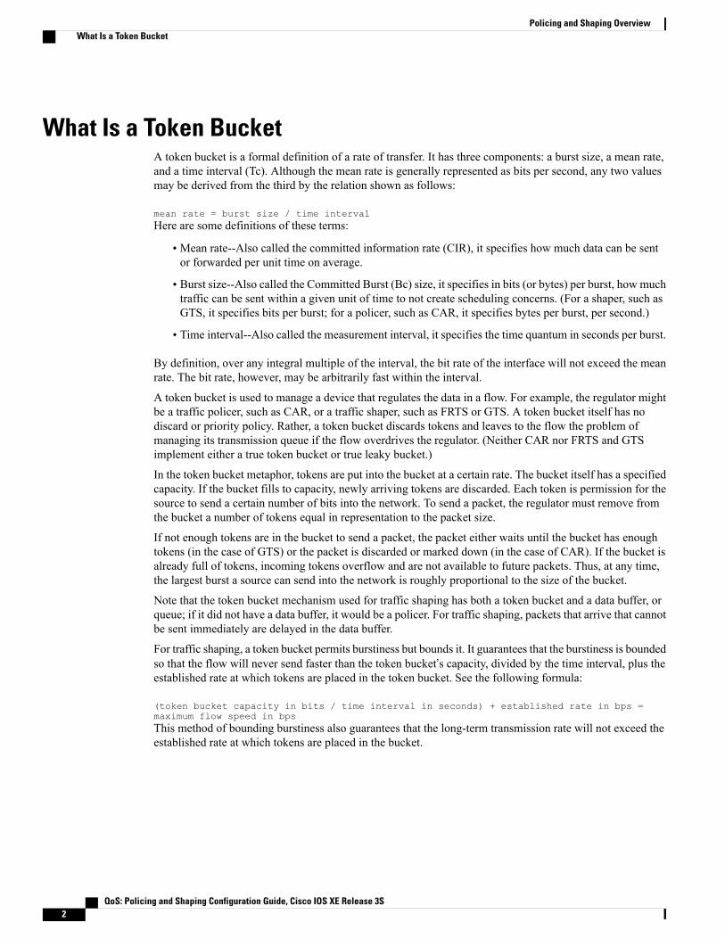
What Is a Token BucketA token bucket is a formal definition of a rate of transfer. It has three components: a burst size, a mean rate,and a time interval (Tc). Although the mean rate is generally represented as bits per second, any two valuesmay be derived from the third by the relation shown as follows:
mean rate = burst size / time intervalHere are some definitions of these terms:
• Mean rate--Also called the committed information rate (CIR), it specifies how much data can be sentor forwarded per unit time on average.
• Burst size--Also called the Committed Burst (Bc) size, it specifies in bits (or bytes) per burst, how muchtraffic can be sent within a given unit of time to not create scheduling concerns. (For a shaper, such asGTS, it specifies bits per burst; for a policer, such as CAR, it specifies bytes per burst, per second.)
• Time interval--Also called the measurement interval, it specifies the time quantum in seconds per burst.
By definition, over any integral multiple of the interval, the bit rate of the interface will not exceed the meanrate. The bit rate, however, may be arbitrarily fast within the interval.
A token bucket is used to manage a device that regulates the data in a flow. For example, the regulator mightbe a traffic policer, such as CAR, or a traffic shaper, such as FRTS or GTS. A token bucket itself has nodiscard or priority policy. Rather, a token bucket discards tokens and leaves to the flow the problem ofmanaging its transmission queue if the flow overdrives the regulator. (Neither CAR nor FRTS and GTSimplement either a true token bucket or true leaky bucket.)
In the token bucket metaphor, tokens are put into the bucket at a certain rate. The bucket itself has a specifiedcapacity. If the bucket fills to capacity, newly arriving tokens are discarded. Each token is permission for thesource to send a certain number of bits into the network. To send a packet, the regulator must remove fromthe bucket a number of tokens equal in representation to the packet size.
If not enough tokens are in the bucket to send a packet, the packet either waits until the bucket has enoughtokens (in the case of GTS) or the packet is discarded or marked down (in the case of CAR). If the bucket isalready full of tokens, incoming tokens overflow and are not available to future packets. Thus, at any time,the largest burst a source can send into the network is roughly proportional to the size of the bucket.
Note that the token bucket mechanism used for traffic shaping has both a token bucket and a data buffer, orqueue; if it did not have a data buffer, it would be a policer. For traffic shaping, packets that arrive that cannotbe sent immediately are delayed in the data buffer.
For traffic shaping, a token bucket permits burstiness but bounds it. It guarantees that the burstiness is boundedso that the flow will never send faster than the token bucket’s capacity, divided by the time interval, plus theestablished rate at which tokens are placed in the token bucket. See the following formula:
(token bucket capacity in bits / time interval in seconds) + established rate in bps =maximum flow speed in bpsThis method of bounding burstiness also guarantees that the long-term transmission rate will not exceed theestablished rate at which tokens are placed in the bucket.
QoS: Policing and Shaping Configuration Guide, Cisco IOS XE Release 3S2
Policing and Shaping OverviewWhat Is a Token Bucket
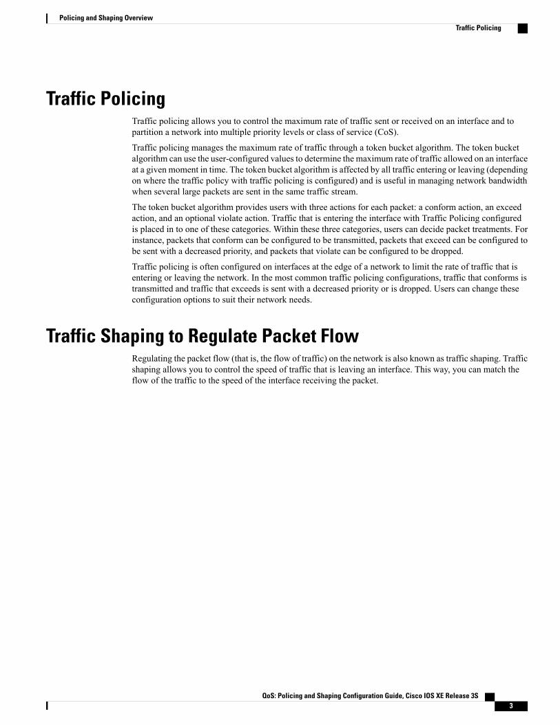
Traffic PolicingTraffic policing allows you to control the maximum rate of traffic sent or received on an interface and topartition a network into multiple priority levels or class of service (CoS).
Traffic policing manages the maximum rate of traffic through a token bucket algorithm. The token bucketalgorithm can use the user-configured values to determine the maximum rate of traffic allowed on an interfaceat a given moment in time. The token bucket algorithm is affected by all traffic entering or leaving (dependingon where the traffic policy with traffic policing is configured) and is useful in managing network bandwidthwhen several large packets are sent in the same traffic stream.
The token bucket algorithm provides users with three actions for each packet: a conform action, an exceedaction, and an optional violate action. Traffic that is entering the interface with Traffic Policing configuredis placed in to one of these categories. Within these three categories, users can decide packet treatments. Forinstance, packets that conform can be configured to be transmitted, packets that exceed can be configured tobe sent with a decreased priority, and packets that violate can be configured to be dropped.
Traffic policing is often configured on interfaces at the edge of a network to limit the rate of traffic that isentering or leaving the network. In the most common traffic policing configurations, traffic that conforms istransmitted and traffic that exceeds is sent with a decreased priority or is dropped. Users can change theseconfiguration options to suit their network needs.
Traffic Shaping to Regulate Packet FlowRegulating the packet flow (that is, the flow of traffic) on the network is also known as traffic shaping. Trafficshaping allows you to control the speed of traffic that is leaving an interface. This way, you can match theflow of the traffic to the speed of the interface receiving the packet.
QoS: Policing and Shaping Configuration Guide, Cisco IOS XE Release 3S 3
Policing and Shaping OverviewTraffic Policing

QoS: Policing and Shaping Configuration Guide, Cisco IOS XE Release 3S4
Policing and Shaping OverviewTraffic Shaping to Regulate Packet Flow

C H A P T E R 2IPv6 QoS: MQC Traffic Shaping
Traffic shaping allows you to limit the packet dequeue rate by holding additional packets in the queues andforwarding them as specified by parameters configured for traffic shaping features
• Finding Feature Information, page 5
• Information About IPv6 QoS: MQC Traffic Shaping, page 5
• Additional References, page 6
• Feature Information for IPv6 QoS: MQC Traffic Shaping, page 7
Finding Feature InformationYour software release may not support all the features documented in this module. For the latest caveats andfeature information, see Bug Search Tool and the release notes for your platform and software release. Tofind information about the features documented in this module, and to see a list of the releases in which eachfeature is supported, see the feature information table at the end of this module.
Use Cisco Feature Navigator to find information about platform support and Cisco software image support.To access Cisco Feature Navigator, go to www.cisco.com/go/cfn. An account on Cisco.com is not required.
Information About IPv6 QoS: MQC Traffic Shaping
Implementation Strategy for QoS for IPv6IPv6 packets are forwarded by paths that are different from those for IPv4. QoS features supported for IPv6environments include packet classification, queuing, traffic shaping, weighted random early detection (WRED),class-based packet marking, and policing of IPv6 packets. These features are available at both the processswitching and Cisco Express Forwarding switching paths of IPv6.
All of the QoS features available for IPv6 environments are managed from the modular QoS command-lineinterface (MQC). The MQC allows you to define traffic classes, create and configure traffic policies (policymaps), and then attach those traffic policies to interfaces.
QoS: Policing and Shaping Configuration Guide, Cisco IOS XE Release 3S 5

To implement QoS in networks that are running IPv6, follow the same steps that you would follow to implementQoS in networks running only IPv4. At a very high level, the basic steps for implementing QoS are as follows:
• Know which applications in your network need QoS.
• Understand the characteristics of the applications so that you can make decisions about which QoSfeatures would be appropriate.
• Know your network topology so that you know how link layer header sizes are affected by changes andforwarding.
• Create classes based on the criteria that you establish for your network. In particular, if the same networkis also carrying IPv4 traffic along with IPv6 traffic, decide if you want to treat both of them the sameway or treat them separately and specify match criteria accordingly. If you want to treat them the same,use match statements such asmatch precedence, match dscp, set precedence, and set dscp. If youwant to treat them separately, add match criteria such asmatch protocol ip andmatch protocol ipv6in a match-all class map.
• Create a policy to mark each class.
•Work from the edge toward the core in applying QoS features.
• Build the policy to treat the traffic.
• Apply the policy.
Traffic Policing in IPv6 EnvironmentsCongestion management for IPv6 is similar to IPv4, and the commands used to configure queueing and trafficshaping features for IPv6 environments are the same commands as those used for IPv4. Traffic shaping allowsyou to limit the packet dequeue rate by holding additional packets in the queues and forwarding them asspecified by parameters configured for traffic shaping features. Traffic shaping uses flow-based queueing bydefault. CBWFQ can be used to classify and prioritize the packets. Class-based policer and generic trafficshaping (GTS) or Frame Relay traffic shaping (FRTS) can be used for conditioning and policing traffic.
Additional ReferencesRelated Documents
Document TitleRelated Topic
IPv6 Configuration GuideIPv6 addressing and connectivity
Cisco IOSMaster Commands List,All Releases
Cisco IOS commands
Cisco IOS IPv6 CommandReference
IPv6 commands
Cisco IOS IPv6 Feature MappingCisco IOS IPv6 features
QoS: Policing and Shaping Configuration Guide, Cisco IOS XE Release 3S6
IPv6 QoS: MQC Traffic ShapingTraffic Policing in IPv6 Environments

Standards and RFCs
TitleStandard/RFC
IPv6 RFCsRFCs for IPv6
MIBs
MIBs LinkMIB
To locate and downloadMIBs for selected platforms,Cisco IOS releases, and feature sets, use Cisco MIBLocator found at the following URL:
http://www.cisco.com/go/mibs
Technical Assistance
LinkDescription
http://www.cisco.com/cisco/web/support/index.htmlThe Cisco Support and Documentation websiteprovides online resources to download documentation,software, and tools. Use these resources to install andconfigure the software and to troubleshoot and resolvetechnical issues with Cisco products and technologies.Access to most tools on the Cisco Support andDocumentation website requires a Cisco.com user IDand password.
Feature Information for IPv6 QoS: MQC Traffic ShapingThe following table provides release information about the feature or features described in this module. Thistable lists only the software release that introduced support for a given feature in a given software releasetrain. Unless noted otherwise, subsequent releases of that software release train also support that feature.
Use Cisco Feature Navigator to find information about platform support and Cisco software image support.To access Cisco Feature Navigator, go to www.cisco.com/go/cfn. An account on Cisco.com is not required.
QoS: Policing and Shaping Configuration Guide, Cisco IOS XE Release 3S 7
IPv6 QoS: MQC Traffic ShapingFeature Information for IPv6 QoS: MQC Traffic Shaping

Table 1: Feature Information for IPv6 QoS: MQC Traffic Shaping
Feature InformationReleasesFeature Name
Traffic shaping allows you to limitthe packet dequeue rate by holdingadditional packets in the queuesand forwarding them as specifiedby parameters configured for trafficshaping features.
Cisco IOS XE Release 2.1IPv6 QoS: MQC Traffic Shaping
QoS: Policing and Shaping Configuration Guide, Cisco IOS XE Release 3S8
IPv6 QoS: MQC Traffic ShapingFeature Information for IPv6 QoS: MQC Traffic Shaping

C H A P T E R 3Distribution of Remaining Bandwidth Using Ratio
The Distribution of Remaining Bandwidth Using Ratio feature allows service providers to configure abandwidth-remaining ratio on subinterfaces and class queues. This ratio specifies the relative weight of asubinterface or queue with respect to other subinterfaces or queues. During congestion, the router uses thisbandwidth-remaining ratio to determine the amount of excess bandwidth (unused by priority traffic) toallocate to a class of nonpriority traffic. The router allocates excess bandwidth relative to the othersubinterface-level queues and class queues configured on the physical interface. By administration of abandwidth-remaining ratio, traffic priority is not based solely on speed. Instead, the service provider canbase priority on alternative factors such as service product and subscription rate.
• Finding Feature Information, page 9
• Prerequisites for Distribution of Remaining Bandwidth Using Ratio, page 10
• Restrictions for Distribution of Remaining Bandwidth Using Ratio, page 10
• Information About Distribution of Remaining Bandwidth Using Ratio, page 10
• How to Configure Distribution of Remaining Bandwidth Using Ratio, page 11
• Configuration Examples for Distribution of Remaining Bandwidth Using Ratio, page 20
• Additional References, page 24
• Feature Information for Distribution of Remaining Bandwidth Using Ratio, page 25
Finding Feature InformationYour software release may not support all the features documented in this module. For the latest caveats andfeature information, see Bug Search Tool and the release notes for your platform and software release. Tofind information about the features documented in this module, and to see a list of the releases in which eachfeature is supported, see the feature information table at the end of this module.
Use Cisco Feature Navigator to find information about platform support and Cisco software image support.To access Cisco Feature Navigator, go to www.cisco.com/go/cfn. An account on Cisco.com is not required.
QoS: Policing and Shaping Configuration Guide, Cisco IOS XE Release 3S 9
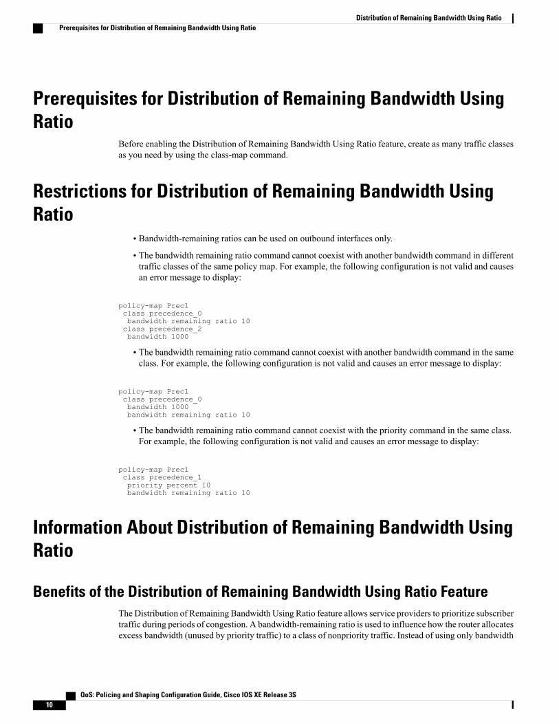
Prerequisites for Distribution of Remaining Bandwidth UsingRatio
Before enabling the Distribution of Remaining Bandwidth Using Ratio feature, create as many traffic classesas you need by using the class-map command.
Restrictions for Distribution of Remaining Bandwidth UsingRatio
• Bandwidth-remaining ratios can be used on outbound interfaces only.
• The bandwidth remaining ratio command cannot coexist with another bandwidth command in differenttraffic classes of the same policy map. For example, the following configuration is not valid and causesan error message to display:
policy-map Prec1class precedence_0bandwidth remaining ratio 10class precedence_2bandwidth 1000
• The bandwidth remaining ratio command cannot coexist with another bandwidth command in the sameclass. For example, the following configuration is not valid and causes an error message to display:
policy-map Prec1class precedence_0bandwidth 1000bandwidth remaining ratio 10
• The bandwidth remaining ratio command cannot coexist with the priority command in the same class.For example, the following configuration is not valid and causes an error message to display:
policy-map Prec1class precedence_1priority percent 10bandwidth remaining ratio 10
Information About Distribution of Remaining Bandwidth UsingRatio
Benefits of the Distribution of Remaining Bandwidth Using Ratio FeatureThe Distribution of Remaining Bandwidth Using Ratio feature allows service providers to prioritize subscribertraffic during periods of congestion. A bandwidth-remaining ratio is used to influence how the router allocatesexcess bandwidth (unused by priority traffic) to a class of nonpriority traffic. Instead of using only bandwidth
QoS: Policing and Shaping Configuration Guide, Cisco IOS XE Release 3S10
Distribution of Remaining Bandwidth Using RatioPrerequisites for Distribution of Remaining Bandwidth Using Ratio

rate, the router considers configured minimum bandwidth rates, maximum bandwidth rates, andbandwidth-remaining ratios when determining excess bandwidth allocation. A bandwidth-remaining ratioadds more flexibility in prioritizing traffic and enables you to influence excess bandwidth allocation by basingthe bandwidth-remaining ratio on factors other than speed.
With bandwidth-remaining ratios, service providers have more flexibility in assigning priority to subinterfacesand queues during congestion. In addition to speed, you can base the bandwidth-remaining ratio on alternativefactors, such as a service product or subscription rate. In this way, for example, you can give higher weightto subinterfaces that carry business services and lower weight to subinterfaces that carry residential services.
Bandwidth-Remaining Ratio FunctionalityA bandwidth-remaining ratio, specified by the bandwidth remaining ratio command, is a value from 1 to1000 that is used to determine the amount of unused (excess) bandwidth to allocate to a class-level queue orsubinterface-level queue during congestion. The router allocates the excess bandwidth relative to the otherclass-level queues and subinterface-level queues configured on the physical interface. The bandwidth-remainingratio value does not indicate a percentage. As the name implies, a ratio is used. For example, a subinterfacewith a bandwidth-remaining ratio of 100 receives 10 times the unused (excess) bandwidth during congestionthan a subinterface with a bandwidth-remaining ratio of 10.
Without bandwidth-remaining ratios, the queueing mechanism or scheduler on the router allocates unused(excess) bandwidth equally among the classes or subinterfaces.
With bandwidth-remaining ratios, unused (excess) bandwidth allocation can be based on factors other thanthe bandwidth rate (for example, the service product or the subscription rate).
Using the bandwidth remaining ratio command, the bandwidth-remaining ratio can be configured differentlyon each subinterface or class. The bandwidth-remaining ratio can range from 1 to 1000. For example, if thereare three subscribers, and the bandwidth-remaining ratios are configured as 9, 7, and 1, and if after prioritytraffic is served, there are 1700 kbps of excess bandwidth, the subscribers get 900 kbps, 700 kbps, and 100kbps, respectively.
How to Configure Distribution of Remaining Bandwidth UsingRatio
You can apply bandwidth-remaining ratios to subinterfaces and/or classes queues.
Configuring and Applying Bandwidth-Remaining Ratios to Subinterfaces
You can apply bandwidth-remaining ratios to outbound subinterfaces only.
>
Note
QoS: Policing and Shaping Configuration Guide, Cisco IOS XE Release 3S 11
Distribution of Remaining Bandwidth Using RatioBandwidth-Remaining Ratio Functionality

SUMMARY STEPS
1. enable2. configure terminal3. policy-map child-policy-name4. class class-map-name5. bandwidth bandwidth-kbps6. Repeat Steps Configuring and Applying Bandwidth-Remaining Ratios to Subinterfaces and Configuring
and Applying Bandwidth-Remaining Ratios to Subinterfaces to configure additional traffic classes, ifneeded.
7. exit8. exit9. policy-map parent-policy-name10. class class-default11. bandwidth remaining ratio ratio12. shape {average | peak} cir [bc] [be]13. service-policy child-policy-name14. exit15. exit16. interface type slot / module / port . subinterface [point-to-point |multipoint]17. service-policy output parent-policy-name18. end
DETAILED STEPS
PurposeCommand or Action
Enables privileged EXEC mode.enableStep 1
Example:
Router> enable
• Enter your password if prompted.
Enters global configuration mode.configure terminal
Example:
Router# configure terminal
Step 2
Creates or modifies a child policy map and enters policy-mapconfiguration mode.
policy-map child-policy-name
Example:
Router(config)# policy-map Child
Step 3
• Enter the name of the child policy map.
QoS: Policing and Shaping Configuration Guide, Cisco IOS XE Release 3S12
Distribution of Remaining Bandwidth Using RatioConfiguring and Applying Bandwidth-Remaining Ratios to Subinterfaces
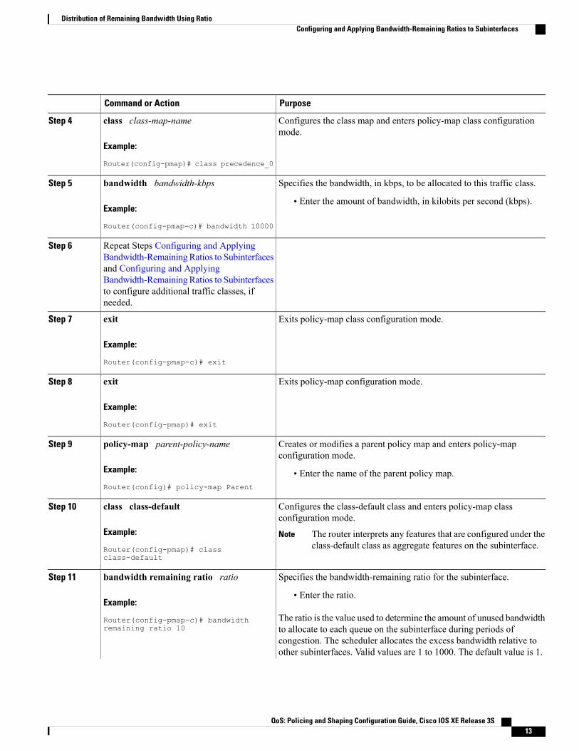
PurposeCommand or Action
Configures the class map and enters policy-map class configurationmode.
class class-map-name
Example:
Router(config-pmap)# class precedence_0
Step 4
Specifies the bandwidth, in kbps, to be allocated to this traffic class.bandwidth bandwidth-kbpsStep 5
Example:
Router(config-pmap-c)# bandwidth 10000
• Enter the amount of bandwidth, in kilobits per second (kbps).
Repeat Steps Configuring and ApplyingBandwidth-RemainingRatios to Subinterfaces
Step 6
and Configuring and ApplyingBandwidth-RemainingRatios to Subinterfacesto configure additional traffic classes, ifneeded.
Exits policy-map class configuration mode.exit
Example:
Router(config-pmap-c)# exit
Step 7
Exits policy-map configuration mode.exit
Example:
Router(config-pmap)# exit
Step 8
Creates or modifies a parent policy map and enters policy-mapconfiguration mode.
policy-map parent-policy-name
Example:
Router(config)# policy-map Parent
Step 9
• Enter the name of the parent policy map.
Configures the class-default class and enters policy-map classconfiguration mode.
class class-default
Example:
Router(config-pmap)# classclass-default
Step 10
The router interprets any features that are configured under theclass-default class as aggregate features on the subinterface.
Note
Specifies the bandwidth-remaining ratio for the subinterface.bandwidth remaining ratio ratioStep 11
Example:
Router(config-pmap-c)# bandwidthremaining ratio 10
• Enter the ratio.
The ratio is the value used to determine the amount of unused bandwidthto allocate to each queue on the subinterface during periods ofcongestion. The scheduler allocates the excess bandwidth relative toother subinterfaces. Valid values are 1 to 1000. The default value is 1.
QoS: Policing and Shaping Configuration Guide, Cisco IOS XE Release 3S 13
Distribution of Remaining Bandwidth Using RatioConfiguring and Applying Bandwidth-Remaining Ratios to Subinterfaces
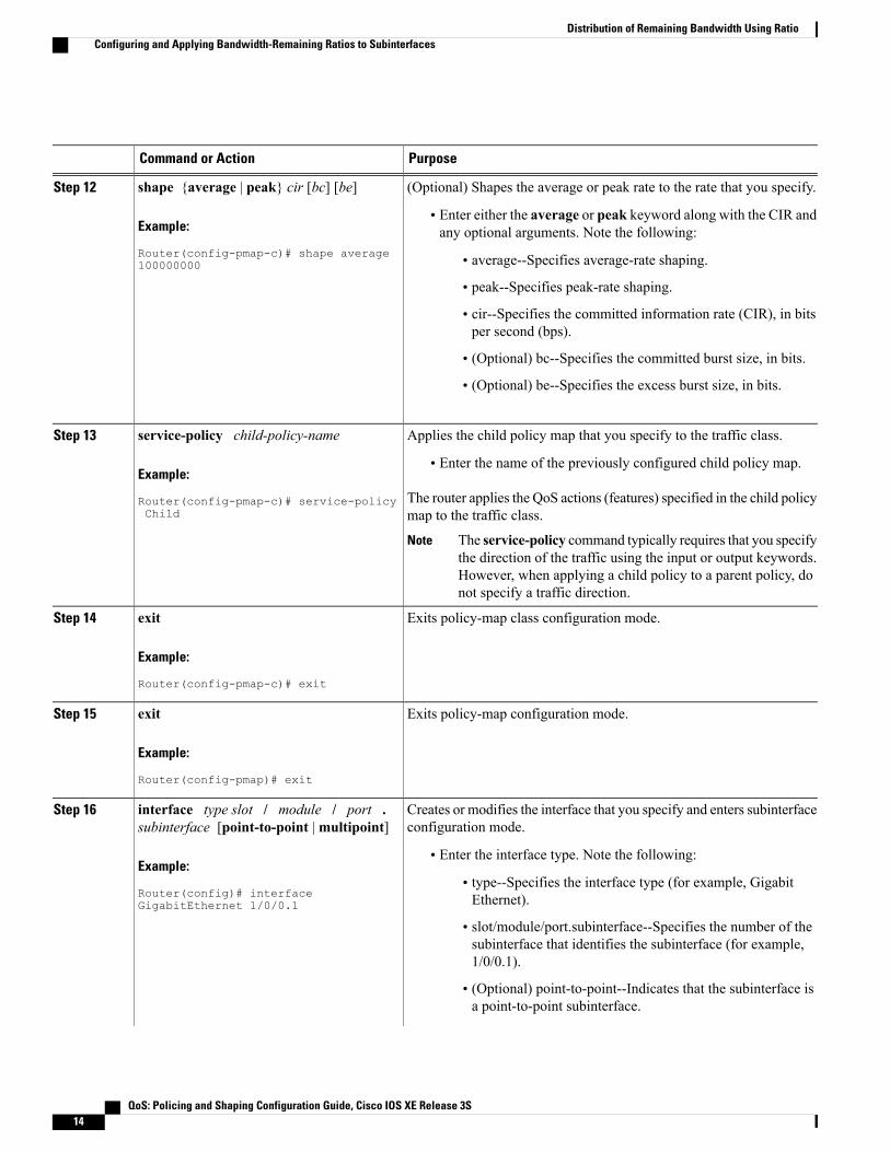
PurposeCommand or Action
(Optional) Shapes the average or peak rate to the rate that you specify.shape {average | peak} cir [bc] [be]Step 12
Example:
Router(config-pmap-c)# shape average100000000
• Enter either the average or peak keyword along with the CIR andany optional arguments. Note the following:
• average--Specifies average-rate shaping.
• peak--Specifies peak-rate shaping.
• cir--Specifies the committed information rate (CIR), in bitsper second (bps).
• (Optional) bc--Specifies the committed burst size, in bits.
• (Optional) be--Specifies the excess burst size, in bits.
Applies the child policy map that you specify to the traffic class.service-policy child-policy-nameStep 13
Example:
Router(config-pmap-c)# service-policyChild
• Enter the name of the previously configured child policy map.
The router applies the QoS actions (features) specified in the child policymap to the traffic class.
The service-policy command typically requires that you specifythe direction of the traffic using the input or output keywords.However, when applying a child policy to a parent policy, donot specify a traffic direction.
Note
Exits policy-map class configuration mode.exit
Example:
Router(config-pmap-c)# exit
Step 14
Exits policy-map configuration mode.exit
Example:
Router(config-pmap)# exit
Step 15
Creates or modifies the interface that you specify and enters subinterfaceconfiguration mode.
interface type slot / module / port .subinterface [point-to-point |multipoint]
Step 16
Example:
Router(config)# interfaceGigabitEthernet 1/0/0.1
• Enter the interface type. Note the following:
• type--Specifies the interface type (for example, GigabitEthernet).
• slot/module/port.subinterface--Specifies the number of thesubinterface that identifies the subinterface (for example,1/0/0.1).
• (Optional) point-to-point--Indicates that the subinterface isa point-to-point subinterface.
QoS: Policing and Shaping Configuration Guide, Cisco IOS XE Release 3S14
Distribution of Remaining Bandwidth Using RatioConfiguring and Applying Bandwidth-Remaining Ratios to Subinterfaces

PurposeCommand or Action
• (Optional) multipoint--Indicates that the subinterface is apoint-to-multipoint subinterface.
Applies the parent policy map to the subinterface.service-policy output parent-policy-nameStep 17
Example:
Router(config-subif)# service-policyoutput Parent
• Enter the output keyword and the name of the parent policy map.
The router shapes the subinterface traffic to the shaping ratespecified in the parent class-default class and applies the QoSactions (features) specified in the child policy map.
Note
During periods of congestion, the router uses thebandwidth-remaining ratio specified in the parent policy mapto allocate unused bandwidth on this subinterface relative toother subinterfaces.
Note
Returns to privileged EXEC mode.end
Example:
Router(config-subif)# end
Step 18
QoS: Policing and Shaping Configuration Guide, Cisco IOS XE Release 3S 15
Distribution of Remaining Bandwidth Using RatioConfiguring and Applying Bandwidth-Remaining Ratios to Subinterfaces

Configuring and Applying Bandwidth-Remaining Ratios to Class Queues
SUMMARY STEPS
1. enable2. configure terminal3. policy-map child-policy-name4. class class-map-name5. shape {average | peak} cir [bc] [be]6. bandwidth remaining ratio ratio7. Repeat Steps Configuring and Applying Bandwidth-Remaining Ratios to Class Queues, Configuring and
Applying Bandwidth-Remaining Ratios to Class Queues, and Configuring and ApplyingBandwidth-Remaining Ratios to Class Queues for each class queue that you want to define, specifyingthe bandwidth-remaining ratio as applicable.
8. exit9. exit10. policy-map parent-policy-name11. class class-default12. shape {average | peak} cir [bc] [be]13. bandwidth remaining ratio ratio14. service-policy child-policy-name15. exit16. exit17. interface type slot / module / port . subinterface [point-to-point |multipoint]18. service-policy output parent-policy-name19. end
DETAILED STEPS
PurposeCommand or Action
Enables privileged EXEC mode.enableStep 1
Example:
Router> enable
• Enter your password if prompted.
Enters global configuration mode.configure terminal
Example:
Router# configure terminal
Step 2
QoS: Policing and Shaping Configuration Guide, Cisco IOS XE Release 3S16
Distribution of Remaining Bandwidth Using RatioConfiguring and Applying Bandwidth-Remaining Ratios to Class Queues
PurposeCommand or Action
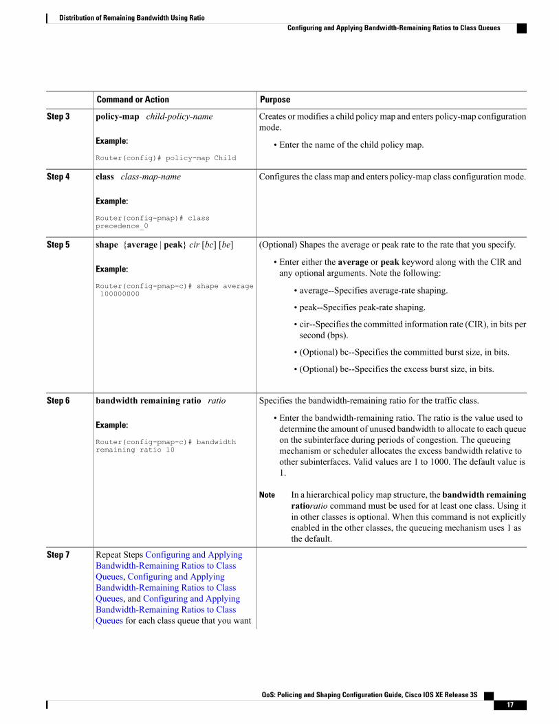
Creates or modifies a child policy map and enters policy-map configurationmode.
policy-map child-policy-name
Example:
Router(config)# policy-map Child
Step 3
• Enter the name of the child policy map.
Configures the class map and enters policy-map class configuration mode.class class-map-name
Example:
Router(config-pmap)# classprecedence_0
Step 4
(Optional) Shapes the average or peak rate to the rate that you specify.shape {average | peak} cir [bc] [be]Step 5
Example:
Router(config-pmap-c)# shape average100000000
• Enter either the average or peak keyword along with the CIR andany optional arguments. Note the following:
• average--Specifies average-rate shaping.
• peak--Specifies peak-rate shaping.
• cir--Specifies the committed information rate (CIR), in bits persecond (bps).
• (Optional) bc--Specifies the committed burst size, in bits.
• (Optional) be--Specifies the excess burst size, in bits.
Specifies the bandwidth-remaining ratio for the traffic class.bandwidth remaining ratio ratioStep 6
Example:
Router(config-pmap-c)# bandwidthremaining ratio 10
• Enter the bandwidth-remaining ratio. The ratio is the value used todetermine the amount of unused bandwidth to allocate to each queueon the subinterface during periods of congestion. The queueingmechanism or scheduler allocates the excess bandwidth relative toother subinterfaces. Valid values are 1 to 1000. The default value is1.
In a hierarchical policy map structure, the bandwidth remainingratioratio command must be used for at least one class. Using itin other classes is optional. When this command is not explicitlyenabled in the other classes, the queueing mechanism uses 1 asthe default.
Note
Repeat Steps Configuring and ApplyingBandwidth-Remaining Ratios to Class
Step 7
Queues, Configuring and ApplyingBandwidth-Remaining Ratios to ClassQueues, and Configuring and ApplyingBandwidth-Remaining Ratios to ClassQueues for each class queue that you want
QoS: Policing and Shaping Configuration Guide, Cisco IOS XE Release 3S 17
Distribution of Remaining Bandwidth Using RatioConfiguring and Applying Bandwidth-Remaining Ratios to Class Queues

PurposeCommand or Action
to define, specifying thebandwidth-remaining ratio as applicable.
Exits policy-map class configuration mode.exit
Example:
Router(config-pmap-c)# exit
Step 8
Exits policy-map configuration mode.exit
Example:
Router(config-pmap)# exit
Step 9
Creates or modifies a parent policy map and enters policy-mapconfiguration mode.
policy-map parent-policy-name
Example:
Router(config)# policy-map Parent
Step 10
• Enter the name of the parent policy map.
Configures the class-default class and enters policy-map class configurationmode.
class class-default
Example:
Router(config-pmap)# classclass-default
Step 11
The router interprets any features that are configured under theclass-default class as aggregate features on the subinterface.
Note
(Optional) Shapes the average or peak rate to the rate that you specify.shape {average | peak} cir [bc] [be]Step 12
Example:
Router(config-pmap-c)# shape average100000000
• Enter either the average or peak keyword along with the CIR andany optional arguments. Note the following:
• average--Specifies average-rate shaping.
• peak--Specifies peak-rate shaping.
• cir--Specifies the committed information rate (CIR), in bits persecond (bps).
• (Optional) bc--Specifies the committed burst size, in bits.
• (Optional) be--Specifies the excess burst size, in bits.
(Optional for class-default or other classes in a hierarchical policy mapstructure) Specifies the bandwidth-remaining ratio for the subinterface.
bandwidth remaining ratio ratio
Example:
Router(config-pmap-c)# bandwidthremaining ratio 10
Step 13
• Enter the bandwidth-remaining ratio. The ratio is the value used todetermine the amount of unused bandwidth to allocate to each queueon the subinterface during periods of congestion. The queueingmechanism or scheduler allocates the excess bandwidth relative toother subinterfaces. Valid values are 1 to 1000. The default value is1.
QoS: Policing and Shaping Configuration Guide, Cisco IOS XE Release 3S18
Distribution of Remaining Bandwidth Using RatioConfiguring and Applying Bandwidth-Remaining Ratios to Class Queues

PurposeCommand or Action
In a hierarchical policy map structure, the bandwidth remainingratioratio command must be used for at least one class. Using itin other classes is optional. When this command is not explicitlyenabled in the other classes, the queueing mechanism uses 1 asthe default.
Note
Applies the child policy map that you specify to the traffic class.service-policy child-policy-nameStep 14
Example:
Router(config-pmap-c)# service-policyChild
• Enter the name of the child policy map. The router applies the QoSactions (features) specified in the child policy map to the traffic class.
The service-policycommand typically requires that you specifythe direction of the traffic using the input or output keywords.However, when applying a child policy map to a parent policymap, do not specify traffic direction.
Note
Exits policy-map class configuration mode.exit
Example:
Router(config-pmap-c)# exit
Step 15
Exits policy-map configuration mode.exit
Example:
Router(config-pmap)# exit
Step 16
Creates or modifies the interface that you specify and enters subinterfaceconfiguration mode.
interface type slot / module / port. subinterface [point-to-point |multipoint]
Step 17
• Enter the interface type. Note the following:
Example:
Router(config)# interfaceGigabitEthernet 1/0/0.1
• type--Specifies the interface type (for example, GigabitEthernet).
• slot/module/port.subinterface--Specifies the number of thesubinterface that identifies the subinterface (for example,1/0/0.1).
• (Optional) point-to-point--Indicates that the subinterface is apoint-to-point subinterface.
• (Optional) multipoint--Indicates that the subinterface is apoint-to-multipoint subinterface.
Attaches the parent policy map to the subinterface.service-policy output parent-policy-nameStep 18
Example:
Router(config-subif)# service-policyoutput Parent
• Enter the outputkeyword and the name of the parent policy map.
When congestion occurs, the class queues receive bandwidthaccording to the specified class-level bandwidth-remaining ratios.
Note
QoS: Policing and Shaping Configuration Guide, Cisco IOS XE Release 3S 19
Distribution of Remaining Bandwidth Using RatioConfiguring and Applying Bandwidth-Remaining Ratios to Class Queues

PurposeCommand or Action
Returns to privileged EXEC mode.end
Example:
Router(config-subif)# end
Step 19
Configuration Examples for Distribution of Remaining BandwidthUsing Ratio
Example Configuring Bandwidth-Remaining Ratios on Ethernet SubinterfacesThe following example shows how to configure bandwidth-remaining ratios on an Ethernet subinterface usinga hierarchical policy. In the example, Gigabit Ethernet subinterface 1/0/0.1 is shaped to 100 Mbps. Duringcongestion, the router uses the bandwidth-remaining ratio of 10 to determine the amount of excess bandwidth(unused by priority traffic) to allocate to the nonpriority traffic on subinterface 1/0/0.1, relative to the othersubinterface-level and class-level queues on the interface.
policy-map Childclass precedence_0bandwidth 10000class precedence_1shape average 100000bandwidth 100
policy-map Parentclass class-defaultbandwidth remaining ratio 10shape average 100000000service-policy Child
interface GigabitEthernet1/0/0.1encapsulation dot1Q 100ip address 10.1.0.1 255.255.255.0service-policy output Parent
Example Verifying Bandwidth-Remaining Ratios on Class QueuesIn the following sample configuration, vlan10_policy is applied on the Gigabit Ethernet subinterface 1/0/0.10and vlan20_policy is applied on the Gigabit Ethernet subinterface 1/0/0.20. During congestion on the interface,subinterface Gigabit Ethernet 1/0/0.20 has 10 times more available bandwidth than subinterface GigabitEthernet 1/0/0.10 because the bandwidth-remaining ratio for subinterface Gigabit Ethernet 1/0/0.20 is 10times more than the bandwidth-remaining ratio for subinterface 1/0/0.10: 100 on subinterface 1/0/0.20 and10 on subinterface 1/0/0.10.
When congestion occurs within a subinterface level, the class queues receive bandwidth according to theclass-level bandwidth-remaining ratios. In the example, the bandwidth for classes precedence_0, precedence_1,and precedence_2 is allocated based on the bandwidth-remaining ratios of the classes: 20, 40, and 60,respectively.
QoS: Policing and Shaping Configuration Guide, Cisco IOS XE Release 3S20
Distribution of Remaining Bandwidth Using RatioConfiguration Examples for Distribution of Remaining Bandwidth Using Ratio

Router# show policy-map
Policy Map child-policyClass precedence_0Average Rate Traffic Shapingcir 500000 (bps)bandwidth remaining ratio 20 <---- Class-level ratio
Class precedence_1Average Rate Traffic Shapingcir 500000 (bps)bandwidth remaining ratio 40 <---- Class-level ratio
Class precedence_2Average Rate Traffic Shapingcir 500000 (bps)bandwidth remaining ratio 60 <---- Class-level ratio
Policy Map vlan10_policyClass class-defaultAverage Rate Traffic Shapingcir 1000000 (bps)bandwidth remaining ratio 10 <---- Subinterface-level ratioservice-policy child-policy
Policy Map vlan20_policyClass class-defaultAverage Rate Traffic Shapingcir 1000000 (bps)bandwidth remaining ratio 100 <---- Subinterface-level ratioservice-policy child-policy
interface GigabitEthernet1/0/0.10encapsulation dot1Q 10snmp trap link-statusservice-policy output vlan10_policyinterface GigabitEthernet1/0/0.20encapsulation dot1Q 20snmp trap link-statusservice-policy output vlan20_policy
Example: Verifying Bandwidth Remaining RatiosThe following sample output from the show policy-map interface command indicates that bandwidth-remainingratios are configured on class-level queues in the policy maps named vlan10_policy and child-policy, whichare attached to Gigabit Ethernet subinterface 1/0/0.10.
Router# show policy-map interface GigabitEthernet 1/0/0.10GigabitEthernet1/0/0.10Service-policy output: vlan10_policyClass-map: class-default (match-any)0 packets, 0 bytes5 minute offered rate 0 bps, drop rate 0 bpsMatch: anyQueueingqueue limit 64 packets(queue depth/total drops/no-buffer drops) 0/0/0(pkts output/bytes output) 0/0shape (average) cir 1000000, bc 4000, be 4000target shape rate 1000000bandwidth remaining ratio 10Service-policy : child-policyClass-map: precedence_0 (match-all)0 packets, 0 bytes5 minute offered rate 0 bps, drop rate 0 bpsMatch: ip precedence 0Queueingqueue limit 64 packets(queue depth/total drops/no-buffer drops) 0/0/0(pkts output/bytes output) 0/0shape (average) cir 500000, bc 2000, be 2000target shape rate 500000
QoS: Policing and Shaping Configuration Guide, Cisco IOS XE Release 3S 21
Distribution of Remaining Bandwidth Using RatioExample: Verifying Bandwidth Remaining Ratios

bandwidth remaining ratio 20Class-map: precedence_1 (match-all)0 packets, 0 bytes5 minute offered rate 0 bps, drop rate 0 bpsMatch: ip precedence 1Queueingqueue limit 64 packets(queue depth/total drops/no-buffer drops) 0/0/0(pkts output/bytes output) 0/0shape (average) cir 500000, bc 2000, be 2000target shape rate 500000bandwidth remaining ratio 40
Class-map: precedence_2 (match-all)0 packets, 0 bytes5 minute offered rate 0 bps, drop rate 0 bpsMatch: ip precedence 2Queueingqueue limit 64 packets(queue depth/total drops/no-buffer drops) 0/0/0(pkts output/bytes output) 0/0shape (average) cir 500000, bc 2000, be 2000target shape rate 500000bandwidth remaining ratio 60
Class-map: class-default (match-any)0 packets, 0 bytes5 minute offered rate 0 bps, drop rate 0 bpsMatch: any
queue limit 64 packets(queue depth/total drops/no-buffer drops) 0/0/0(pkts output/bytes output) 0/0
The following sample output from the show policy-map interface command indicates that bandwidth-remainingratios are configured on class-level queues in the policy maps named vlan20_policy and child-policy, whichare attached to Gigabit Ethernet subinterface 1/0/0.20.
Router# show policy-map interface GigabitEthernet 1/0/0.20GigabitEthernet1/0/0.20Service-policy output: vlan20_policyClass-map: class-default (match-any)0 packets, 0 bytes5 minute offered rate 0 bps, drop rate 0 bpsMatch: anyQueueingqueue limit 64 packets(queue depth/total drops/no-buffer drops) 0/0/0(pkts output/bytes output) 0/0shape (average) cir 1000000, bc 4000, be 4000target shape rate 1000000bandwidth remaining ratio 100Service-policy : child-policyClass-map: precedence_0 (match-all)0 packets, 0 bytes5 minute offered rate 0 bps, drop rate 0 bpsMatch: ip precedence 0Queueingqueue limit 64 packets(queue depth/total drops/no-buffer drops) 0/0/0(pkts output/bytes output) 0/0shape (average) cir 500000, bc 2000, be 2000target shape rate 500000bandwidth remaining ratio 20
Class-map: precedence_1 (match-all)0 packets, 0 bytes5 minute offered rate 0 bps, drop rate 0 bpsMatch: ip precedence 1Queueingqueue limit 64 packets(queue depth/total drops/no-buffer drops) 0/0/0(pkts output/bytes output) 0/0shape (average) cir 500000, bc 2000, be 2000target shape rate 500000
QoS: Policing and Shaping Configuration Guide, Cisco IOS XE Release 3S22
Distribution of Remaining Bandwidth Using RatioExample: Verifying Bandwidth Remaining Ratios

bandwidth remaining ratio 40Class-map: precedence_2 (match-all)0 packets, 0 bytes5 minute offered rate 0 bps, drop rate 0 bpsMatch: ip precedence 2Queueingqueue limit 64 packets(queue depth/total drops/no-buffer drops) 0/0/0(pkts output/bytes output) 0/0shape (average) cir 500000, bc 2000, be 2000target shape rate 500000bandwidth remaining ratio 60
Class-map: class-default (match-any)0 packets, 0 bytes5 minute offered rate 0 bps, drop rate 0 bpsMatch: any
queue limit 64 packets(queue depth/total drops/no-buffer drops) 0/0/0(pkts output/bytes output) 0/0
The following sample output from the show policy-map command indicates that a bandwidth-remaining ratioof 10 is configured on the parent class-default class of the policy map named vlan10_policy.
Router# show policy-map vlan10_policyPolicy Map vlan10_policyClass class-defaultAverage Rate Traffic Shapingcir 1000000 (bps)bandwidth remaining ratio 10service-policy child-policy
The following sample output from the show policy-map command indicates that a bandwidth-remaining ratioof 100 is configured on the parent class-default class of the policy map named vlan20_policy.
Router# show policy-map vlan20_policyPolicy Map vlan20_policyClass class-defaultAverage Rate Traffic Shapingcir 1000000 (bps)bandwidth remaining ratio 100service-policy child-policy
The following sample output from the show policy-map command indicates that bandwidth-remaining ratiosof 20, 40, and 60 are configured on the class queues precedence_0, precedence_1, and precedence_2,respectively.
Router# show policy-map child-policyPolicy Map child-policyClass precedence_0Average Rate Traffic Shapingcir 500000 (bps)bandwidth remaining ratio 20
Class precedence_1Average Rate Traffic Shapingcir 500000 (bps)bandwidth remaining ratio 40
Class precedence_2Average Rate Traffic Shapingcir 500000 (bps)bandwidth remaining ratio 60
QoS: Policing and Shaping Configuration Guide, Cisco IOS XE Release 3S 23
Distribution of Remaining Bandwidth Using RatioExample: Verifying Bandwidth Remaining Ratios

Additional ReferencesRelated Documents
Document TitleRelated Topic
Cisco IOS Quality of Service Solutions CommandReference
QoS commands: complete command syntax,command modes, command history, defaults, usageguidelines, and examples
"Congestion Avoidance Overview" moduleCongestion avoidance
"Applying QoS Features Using the MQC" moduleClass maps, policy maps, hierarchical policy maps,Modular Quality of Service Command-Line Interface(CLI) (MQC)
"Policing and Shaping Overview" moduleTraffic shaping, traffic policing
Standards
TitleStandard
--No new or modified standards are supported by thisfeature, and support for existing standards has notbeen modified by this feature.
MIBs
MIBs LinkMIB
To locate and downloadMIBs for selected platforms,Cisco IOSXE Software releases, and feature sets, useCisco MIB Locator found at the following URL:
http://www.cisco.com/go/mibs
No new or modified MIBs are supported by thisfeature, and support for existing MIBs has not beenmodified by this feature.
RFCs
TitleRFC
--No new or modified RFCs are supported by thisfeature, and support for existing RFCs has not beenmodified by this feature.
QoS: Policing and Shaping Configuration Guide, Cisco IOS XE Release 3S24
Distribution of Remaining Bandwidth Using RatioAdditional References
Technical Assistance
LinkDescription
http://www.cisco.com/cisco/web/support/index.htmlThe Cisco Support and Documentation websiteprovides online resources to download documentation,software, and tools. Use these resources to install andconfigure the software and to troubleshoot and resolvetechnical issues with Cisco products and technologies.Access to most tools on the Cisco Support andDocumentation website requires a Cisco.com user IDand password.
Feature Information for Distribution of Remaining BandwidthUsing Ratio
The following table provides release information about the feature or features described in this module. Thistable lists only the software release that introduced support for a given feature in a given software releasetrain. Unless noted otherwise, subsequent releases of that software release train also support that feature.
Use Cisco Feature Navigator to find information about platform support and Cisco software image support.To access Cisco Feature Navigator, go to www.cisco.com/go/cfn. An account on Cisco.com is not required.
QoS: Policing and Shaping Configuration Guide, Cisco IOS XE Release 3S 25
Distribution of Remaining Bandwidth Using RatioFeature Information for Distribution of Remaining Bandwidth Using Ratio

Table 2: Feature Information for Distribution of Remaining Bandwidth Using Ratio
Feature InformationReleasesFeature Name
The Distribution of RemainingBandwidth Using Ratio featureallows service providers toconfigure a bandwidth-remainingratio on subinterfaces and classqueues. This ratio specifies therelative weight of a subinterface orqueue with respect to othersubinterfaces or queues. Duringcongestion, the router uses thisbandwidth-remaining ratio todetermine the amount of excessbandwidth (unused by prioritytraffic) to allocate to a class ofnonpriority traffic.
In Cisco IOS XE Release 2.1, thisfeature was introduced on CiscoASR 1000 Series Routers.
The following commands wereintroduced ormodified:bandwidthremaining ratio, showpolicy-map, show policy-mapinterface.
Cisco IOS XE Release 2.1MQC--Distribution of RemainingBandwidth Using Ratio
QoS: Policing and Shaping Configuration Guide, Cisco IOS XE Release 3S26
Distribution of Remaining Bandwidth Using RatioFeature Information for Distribution of Remaining Bandwidth Using Ratio

C H A P T E R 4QoS Percentage-Based Shaping
The QoS: Percentage-Based Shaping feature allows you to configure traffic shaping on the basis of apercentage of bandwidth available on the interface. This feature also allows you to specify the committed(conform) burst (bc) size and the excess (peak) burst (be) size (used for configuring traffic shaping) inmilliseconds (ms). Configuring traffic shaping in this manner enables you to use the same policy map formultiple interfaces with differing amounts of bandwidth.
• Finding Feature Information, page 27
• Information About QoS Percentage-Based Shaping, page 27
• How to Configure QoS Percentage-Based Shaping, page 29
• Configuration Examples for QoS Percentage-Based Shaping, page 33
• Additional References, page 35
• Feature Information for QoS Percentage-Based Shaping, page 36
Finding Feature InformationYour software release may not support all the features documented in this module. For the latest caveats andfeature information, see Bug Search Tool and the release notes for your platform and software release. Tofind information about the features documented in this module, and to see a list of the releases in which eachfeature is supported, see the feature information table at the end of this module.
Use Cisco Feature Navigator to find information about platform support and Cisco software image support.To access Cisco Feature Navigator, go to www.cisco.com/go/cfn. An account on Cisco.com is not required.
Information About QoS Percentage-Based Shaping
Benefits for QoS Percentage-Based ShapingThis feature provides the ability to configure traffic shaping on the basis of a percentage of bandwidth availableon an interface, and it allows you to specify burst sizes in milliseconds. Configuring traffic shaping in this
QoS: Policing and Shaping Configuration Guide, Cisco IOS XE Release 3S 27
manner enables you to use the same policy map for multiple interfaces with differing amounts of bandwidth.That is, you do not have to recalculate the bandwidth for each interface or configure a different policy mapfor each type of interface.
Class and Policy Maps for QoS Percentage-Based ShapingTo configure the QoS: Percentage-Based Shaping feature, you must define a traffic class, configure a policymap, and then attach that policy map to the appropriate interface.
In the MQC, the class-map command is used to define a traffic class (which is then associated with a trafficpolicy). The purpose of a traffic class is to classify traffic.
The MQC consists of the following three processes:
• Defining a traffic class with the class-map command.
• Creating a traffic policy by associating the traffic class with one or more QoS features (using thepolicy-map command).
• Attaching the traffic policy to the interface with the service-policy command.
A traffic class contains three major elements: a name, a series of match commands, and, if more than onematch command exists in the traffic class, an instruction on how to evaluate thesematch commands (that is,match-all or match-any). The traffic class is named in the class-map command line; for example, if you enterthe class-map cisco command while configuring the traffic class in the CLI, the traffic class would be named"cisco".
Thematch commands are used to specify various criteria for classifying packets. Packets are checked todetermine whether they match the criteria specified in thematch commands. If a packet matches the specifiedcriteria, that packet is considered a member of the class and is forwarded according to the QoS specificationsset in the traffic policy. Packets that fail to meet any of the matching criteria are classified as members of thedefault traffic class.
Traffic Regulation Mechanisms and Bandwidth PercentagesCisco IOS XE quality of service (QoS) offers two kinds of traffic regulation mechanisms--traffic policingand traffic shaping. A traffic policer typically drops traffic that violates a specific rate. A traffic shaper typicallydelays excess traffic using a buffer to hold packets and shapes the flow when the data rate to a queue is higherthan expected.
Traffic shaping and traffic policing can work in tandem and can be configured in a class map. Class mapsorganize data packets into specific categories ("classes") that can, in turn, receive a user-defined QoS treatmentwhen used in policy maps (sometimes referred to as "service policies").
Before this feature, traffic policing and traffic shaping were configured on the basis of a user-specified amountof bandwidth available on the interface. Policy maps were then configured on the basis of that specific amountof bandwidth, meaning that separate policy maps were required for each interface.
This feature provides the ability to configure traffic policing and traffic shaping on the basis of a percentageof bandwidth available on the interface. Configuring traffic policing and traffic shaping in this manner enablescustomers to use the same policy map for multiple interfaces with differing amounts of bandwidth.
Configuring traffic policing and shaping on the basis of a percentage of bandwidth is accomplished by usingthe police (percent) and shape (percent) commands.
QoS: Policing and Shaping Configuration Guide, Cisco IOS XE Release 3S28
QoS Percentage-Based ShapingClass and Policy Maps for QoS Percentage-Based Shaping

Burst Size Specified in Milliseconds OptionThe purpose of the burst parameters (bc and be) is to specify the amount of traffic to anticipate under normaloperating conditions before traffic is dropped or delayed. Setting sufficiently high burst values helps to ensuregood throughput.
This feature allows you the option of specifying the committed (conform) burst (bc) size and the excess (peak)burst (be) as milliseconds (ms) of the class bandwidth when you configure traffic shaping. The number ofmilliseconds is used to calculate the number of bytes to be used by the QoS: Percentage-Based Shaping feature.
Specifying these burst sizes in milliseconds is accomplished by using the bc and be keywords (and theirassociated arguments) of the shape (percent) command.
How to Configure QoS Percentage-Based Shaping
Configuring a Class and Policy Map
SUMMARY STEPS
1. enable2. configure terminal3. policy-map policy-name4. class {class-name| class-default}5. shape {average | peak} percent percentage [be excess-burst-in-msecms] [bc committed-burst-in-msec
ms]6. end
DETAILED STEPS
PurposeCommand or Action
Enables privileged EXEC mode.enableStep 1
Example:
Router> enable
• Enter your password if prompted.
Enters global configuration mode.configure terminal
Example:
Router# configure terminal
Step 2
QoS: Policing and Shaping Configuration Guide, Cisco IOS XE Release 3S 29
QoS Percentage-Based ShapingBurst Size Specified in Milliseconds Option

PurposeCommand or Action
Specifies the name of the policy map to be created. Enterspolicy-map configuration mode.
policy-map policy-name
Example:
Router(config)# policy-map policy1
Step 3
• Enter the policy map name.
Specifies the class so that you can configure or modify its policy.Enters policy-map class configuration mode.
class {class-name| class-default}
Example:
Router(config-pmap)# class class1
Step 4
• Enter the class name or specify the default class(class-default).
Configures either average or peak rate traffic shaping on thebasis of the specified bandwidth percentage and the optionalburst sizes.
shape {average | peak} percent percentage [beexcess-burst-in-msecms] [bccommitted-burst-in-msecms]
Step 5
Example:
Router(config-pmap-c)# shape average percent25 be 300 ms bc 400 ms
• Enter the bandwidth percentage and optional burst sizes.
Exits policy-map class configuration mode.end
Example:
Router(config-pmap-c)# end
Step 6
Attaching the Policy Map to an Interface
SUMMARY STEPS
1. enable2. configure terminal3. interface type number4. pvc [name] vpi / vci [ilmi | qsaal | smds]5. service-policy {input| output} policy-map-name6. end
DETAILED STEPS
PurposeCommand or Action
Enables higher privilege levels, such as privileged EXEC mode.enableStep 1
QoS: Policing and Shaping Configuration Guide, Cisco IOS XE Release 3S30
QoS Percentage-Based ShapingAttaching the Policy Map to an Interface

PurposeCommand or Action
Example:
Router> enable
• Enter your password if prompted.
Enters global configuration mode.configure terminal
Example:
Router# configure terminal
Step 2
Configures an interface (or subinterface) type and enters interface configurationmode.
interface type number
Example:
Router(config)#
Step 3
• Enter the interface type number.
Depending on the needs of your network, you may need to attach thepolicy map to a subinterface, an ATM PVC, a Frame Relay DLCI, orother type of interface.
Noteinterface serial4/0/0
(Optional) Creates or assigns a name to an ATM PVC and specifies theencapsulation type on an ATM PVC. Enters ATM VC configuration mode.
pvc [name] vpi / vci [ilmi | qsaal |smds]
Step 4
Example:
Router(config-if)# pvc cisco 0/16ilmi
This step is required only if you are attaching the policy map to anATM PVC. If you are not attaching the policy map to an ATM PVC,skip this step and proceed with Attaching the Policy Map to anInterface.
Note
Specifies the name of the policy map to be attached to the input or outputdirection of the interface.
service-policy {input| output}policy-map-name
Step 5
Example:
Router(config-if)#
Policy maps can be configured on ingress or egress routers. They canalso be attached in the input or output direction of an interface. Thedirection (input or output) and the router (ingress or egress) to whichthe policy map should be attached varies according your networkconfiguration. When using the service-policy command to attach thepolicy map to an interface, be sure to choose the router and the interfacedirection that are appropriate for your network configuration.
Note
Traffic shaping is supported on service policies attached to outputinterfaces or output VCs only.
Note
service-policy input policy1
Example:
• Enter the policy map name.
(Optional) Exits interface configuration mode.end
Example:
Router(config-if)# end
Step 6
QoS: Policing and Shaping Configuration Guide, Cisco IOS XE Release 3S 31
QoS Percentage-Based ShapingAttaching the Policy Map to an Interface

Verifying the QoS Percentage-Based Shaping Configuration
SUMMARY STEPS
1. enable2. show class-map [class-map-name]3. show policy-map interface interface-name4. exit
DETAILED STEPS
PurposeCommand or Action
Enables privileged EXEC mode.enableStep 1
Example:
Router> enable
• Enter your password if prompted.
Displays all information about a class map, including the matchcriterion.
show class-map [class-map-name]
Example:
Router# show class-map class1
Step 2
• Enter class map name.
Displays the packet statistics of all classes that are configured forall service policies either on the specified interface or subinterfaceor on a specific PVC on the interface.
show policy-map interface interface-name
Example:
Router#show policy-map interface serial4/0/0
Step 3
• Enter the interface type and number.
(Optional) Exits privileged EXEC mode.exit
Example:
Router# exit
Step 4
Troubleshooting TipsThe commands in the Verifying the QoS Percentage-Based Shaping Configuration, on page 32 section allowyou to verify that you achieved the intended configuration and that the feature is functioning correctly. If,after using the show commands listed above, you find that the configuration is not correct or the feature isnot functioning as expected, perform these operations:
If the configuration is not the one you intended, complete the following procedures:
1 Use the show running-config command and analyze the output of the command.
QoS: Policing and Shaping Configuration Guide, Cisco IOS XE Release 3S32
QoS Percentage-Based ShapingVerifying the QoS Percentage-Based Shaping Configuration
2 If the policy map does not appear in the output of the show running-config command, enable the loggingconsole command.
3 Attach the policy map to the interface again.
If the packets are not beingmatched correctly (for example, the packet counters are not incrementing correctly),complete the following procedures:
1 Run the show policy-mapcommand and analyze the output of the command.
2 Run the show running-config command and analyze the output of the command.
3 Use the show policy-map interface command and analyze the output of the command. Check the thefollowing findings:
1 If a policy map applies queueing, and the packets are matching the correct class, but you see unexpectedresults, compare the number of the packets in the queue with the number of the packets matched.
2 If the interface is congested, and only a small number of the packets are being matched, check thetuning of the transmission (tx) ring, and evaluate whether the queueing is happening on the tx ring. Todo this, use the show controllers command, and look at the value of the tx count in the output of thecommand.
Configuration Examples for QoS Percentage-Based Shaping
Example Specifying Traffic Shaping on the Basis of a Bandwidth PercentageThe following example configures traffic shaping using an average shaping rate on the basis of a percentageof bandwidth. In this example, 25 percent of the bandwidth has been specified. Additionally, an optional bevalue and bc value (300 ms and 400 ms, respectively) have been specified.
Router> enableRouter# configure terminalRouter(config)# policy-map policy1Router(config-pmap)# class class1
Router(config-pmap-c)# shape average percent 25 be 300 ms bc 400 ms
Router(config-pmap-c)# endAfter the policy map and class maps are configured, the policy map is attached to interface as shown in thefollowing example:
Router> enableRouter# configure terminalRouter(config)#
interface serial4/0/0Router(config-if)#
service-policy input policy1Router(config-if)# end
QoS: Policing and Shaping Configuration Guide, Cisco IOS XE Release 3S 33
QoS Percentage-Based ShapingConfiguration Examples for QoS Percentage-Based Shaping
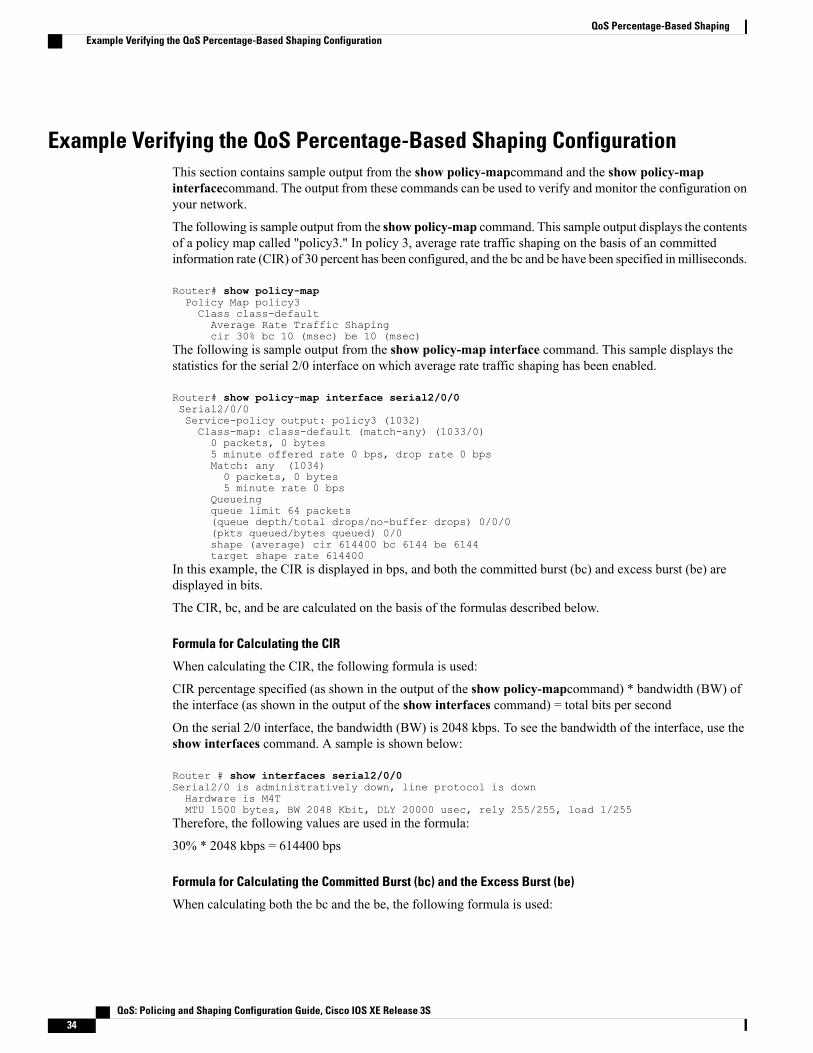
Example Verifying the QoS Percentage-Based Shaping ConfigurationThis section contains sample output from the show policy-mapcommand and the show policy-mapinterfacecommand. The output from these commands can be used to verify and monitor the configuration onyour network.
The following is sample output from the show policy-map command. This sample output displays the contentsof a policy map called "policy3." In policy 3, average rate traffic shaping on the basis of an committedinformation rate (CIR) of 30 percent has been configured, and the bc and be have been specified in milliseconds.
Router# show policy-mapPolicy Map policy3Class class-defaultAverage Rate Traffic Shapingcir 30% bc 10 (msec) be 10 (msec)
The following is sample output from the show policy-map interface command. This sample displays thestatistics for the serial 2/0 interface on which average rate traffic shaping has been enabled.
Router# show policy-map interface serial2/0/0Serial2/0/0Service-policy output: policy3 (1032)Class-map: class-default (match-any) (1033/0)0 packets, 0 bytes5 minute offered rate 0 bps, drop rate 0 bpsMatch: any (1034)0 packets, 0 bytes5 minute rate 0 bps
Queueingqueue limit 64 packets(queue depth/total drops/no-buffer drops) 0/0/0(pkts queued/bytes queued) 0/0shape (average) cir 614400 bc 6144 be 6144target shape rate 614400
In this example, the CIR is displayed in bps, and both the committed burst (bc) and excess burst (be) aredisplayed in bits.
The CIR, bc, and be are calculated on the basis of the formulas described below.
Formula for Calculating the CIR
When calculating the CIR, the following formula is used:
CIR percentage specified (as shown in the output of the show policy-mapcommand) * bandwidth (BW) ofthe interface (as shown in the output of the show interfaces command) = total bits per second
On the serial 2/0 interface, the bandwidth (BW) is 2048 kbps. To see the bandwidth of the interface, use theshow interfaces command. A sample is shown below:
Router # show interfaces serial2/0/0Serial2/0 is administratively down, line protocol is downHardware is M4TMTU 1500 bytes, BW 2048 Kbit, DLY 20000 usec, rely 255/255, load 1/255
Therefore, the following values are used in the formula:
30% * 2048 kbps = 614400 bps
Formula for Calculating the Committed Burst (bc) and the Excess Burst (be)
When calculating both the bc and the be, the following formula is used:
QoS: Policing and Shaping Configuration Guide, Cisco IOS XE Release 3S34
QoS Percentage-Based ShapingExample Verifying the QoS Percentage-Based Shaping Configuration

The bc (or be) in milliseconds (as shown in the show policy-map command) * the CIR in kilobytes (as shownin the show policy-map command) / 1000 = total number of bits
Therefore, the following values are used in the formula:
10 ms * 614400 bps = 6144 bits
Additional ReferencesRelated Documents
Document TitleRelated Topic
Cisco IOS Quality of Service Solutions CommandReference
QoS commands: complete command syntax,command modes, command history, defaults, usageguidelines, and examples
"Applying QoS Features Using the MQC" moduleModular QoSCommand-Line Interface (CLI) (MQC)information about attaching policy maps to interfaces
"Policing and Shaping Overview" moduleTraffic shaping concepts and overview
"Traffic Policing" moduleTraffic policing
Standards
TitleStandard
--No new or modified standards are supported by thisfeature, and support for existing standards has notbeen modified by this feature.
MIBs
MIBs LinkMIB
To locate and downloadMIBs for selected platforms,Cisco IOSXE Software releases, and feature sets, useCisco MIB Locator found at the following URL:
http://www.cisco.com/go/mibs
No new or modified MIBs are supported by thisfeature, and support for existing MIBs has not beenmodified by this feature.
RFCs
TitleRFC
A Single Rate Three Color MarkerRFC 2697
QoS: Policing and Shaping Configuration Guide, Cisco IOS XE Release 3S 35
QoS Percentage-Based ShapingAdditional References

TitleRFC
A Two Rate Three Color MarkerRFC 2698
Technical Assistance
LinkDescription
http://www.cisco.com/cisco/web/support/index.htmlThe Cisco Support and Documentation websiteprovides online resources to download documentation,software, and tools. Use these resources to install andconfigure the software and to troubleshoot and resolvetechnical issues with Cisco products and technologies.Access to most tools on the Cisco Support andDocumentation website requires a Cisco.com user IDand password.
Feature Information for QoS Percentage-Based ShapingThe following table provides release information about the feature or features described in this module. Thistable lists only the software release that introduced support for a given feature in a given software releasetrain. Unless noted otherwise, subsequent releases of that software release train also support that feature.
Use Cisco Feature Navigator to find information about platform support and Cisco software image support.To access Cisco Feature Navigator, go to www.cisco.com/go/cfn. An account on Cisco.com is not required.
QoS: Policing and Shaping Configuration Guide, Cisco IOS XE Release 3S36
QoS Percentage-Based ShapingFeature Information for QoS Percentage-Based Shaping
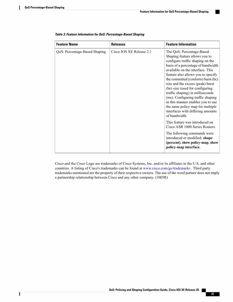
Table 3: Feature Information for QoS: Percentage-Based Shaping
Feature InformationReleasesFeature Name
The QoS: Percentage-BasedShaping feature allows you toconfigure traffic shaping on thebasis of a percentage of bandwidthavailable on the interface. Thisfeature also allows you to specifythe committed (conform) burst (bc)size and the excess (peak) burst(be) size (used for configuringtraffic shaping) in milliseconds(ms). Configuring traffic shapingin this manner enables you to usethe same policy map for multipleinterfaces with differing amountsof bandwidth.
This feature was introduced onCisco ASR 1000 Series Routers.
The following commands wereintroduced or modified: shape(percent), showpolicy-map, showpolicy-map interface.
Cisco IOS XE Release 2.1QoS: Percentage-Based Shaping
Cisco and the Cisco Logo are trademarks of Cisco Systems, Inc. and/or its affiliates in the U.S. and othercountries. A listing of Cisco's trademarks can be found at www.cisco.com/go/trademarks . Third partytrademarks mentioned are the property of their respective owners. The use of the word partner does not implya partnership relationship between Cisco and any other company. (1005R)
QoS: Policing and Shaping Configuration Guide, Cisco IOS XE Release 3S 37
QoS Percentage-Based ShapingFeature Information for QoS Percentage-Based Shaping

QoS: Policing and Shaping Configuration Guide, Cisco IOS XE Release 3S38
QoS Percentage-Based ShapingFeature Information for QoS Percentage-Based Shaping

C H A P T E R 5Ethernet Overhead Accounting
The Ethernet Overhead Accounting feature enables the router to account for downstream Ethernet frameheaders when applying shaping to packets.
• Finding Feature Information, page 39
• Restrictions for Ethernet Overhead Accounting, page 39
• Information About Ethernet Overhead Accounting, page 40
• How to Configure Ethernet Overhead Accounting, page 43
• Configuration Examples for Ethernet Overhead Accounting, page 46
• Additional References, page 47
• Feature Information for Ethernet Overhead Accounting, page 48
Finding Feature InformationYour software release may not support all the features documented in this module. For the latest caveats andfeature information, see Bug Search Tool and the release notes for your platform and software release. Tofind information about the features documented in this module, and to see a list of the releases in which eachfeature is supported, see the feature information table at the end of this module.
Use Cisco Feature Navigator to find information about platform support and Cisco software image support.To access Cisco Feature Navigator, go to www.cisco.com/go/cfn. An account on Cisco.com is not required.
Restrictions for Ethernet Overhead Accounting• Ethernet overhead accounting allows the automatic inclusion of downstream Ethernet frame headers inthe shaped rate.
• If you enable overhead accounting on a child policy, you must enable overhead accounting on the parentpolicy.
QoS: Policing and Shaping Configuration Guide, Cisco IOS XE Release 3S 39
• In a policy map, you must either enable overhead accounting for all classes in the policy or disableoverhead accounting for all classes in the policy. You cannot enable overhead accounting for someclasses and disable overhead accounting for other classes in the same policy.
• Overhead accounting is not reflected in any QoS counters (classification, policing, or queuing).
• Implicit ATM overhead accounting for policers are not supported.
• Implicit L2 overhead (ATM or otherwise) for policers are not supported for certain logical targets(tunnels) when the policy is applied to the logical target. The same limitation exists for queuing andscheduling overhead accounting.
• Police overhead cannot be configured on conditional policers (priority and rate), however, the priorityqueue it used will inherit the queueing overhead from parent shaper if configured.
• Police overhead is not added to the counters and are not reflected in statistics reported by the controlplane.
• The overhead accounting type or value used by policing within a policy map and between the parentpolicy map and the child policy map (in a hierarchical policy map structure) must be consistent.
• The overhead accounting type or value used by queuing features within a policy map and between theparent policy map and the child policy map (in a hierarchical policy map structure) must be consistent.
• In releases preceding to Cisco IOS XE Release 3.9S, the router does not support overhead accountingupdates on attached policies and the policy must be detached from the interface before the overhead canbe modified, then the policy can be reattached to the interface.
• The router does not support overhead accounting for classes with fair-queue, which includes the followingscenarios:
◦When used in conjunction with shape in the same class
◦When used in conjunction with bandwidth in the same class
◦When inherited from a parent or grandparent class through the Parent Level Overhead Accountingfeature introduced in Cisco IOS XE Release 3.9S
Information About Ethernet Overhead Accounting
Benefits of Ethernet Overhead AccountingThe Ethernet Overhead Accounting feature enables the router to account for downstream Ethernet frameheaders when applying shaping to packets. A user-defined offset specifies the number of overhead bytes thatthe router is to use when calculating the overhead per packet. Valid offset values are from +63 bytes to -63bytes of overhead. Before applying shaping, the router calculates the overhead.
Any interface that supports QoS policies will support overhead accounting. Using the policy-map, shape orbandwidth command, you can configure accounting on the interfaces.
QoS: Policing and Shaping Configuration Guide, Cisco IOS XE Release 3S40
Ethernet Overhead AccountingInformation About Ethernet Overhead Accounting
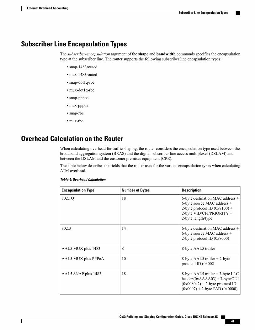
Subscriber Line Encapsulation TypesThe subscriber-encapsulation argument of the shape and bandwidth commands specifies the encapsulationtype at the subscriber line. The router supports the following subscriber line encapsulation types:
• snap-1483routed
• mux-1483routed
• snap-dot1q-rbe
• mux-dot1q-rbe
• snap-pppoa
• mux-pppoa
• snap-rbe
• mux-rbe
Overhead Calculation on the RouterWhen calculating overhead for traffic shaping, the router considers the encapsulation type used between thebroadband aggregation system (BRAS) and the digital subscriber line access multiplexer (DSLAM) andbetween the DSLAM and the customer premises equipment (CPE).
The table below describes the fields that the router uses for the various encapsulation types when calculatingATM overhead.
Table 4: Overhead Calculation
DescriptionNumber of BytesEncapsulation Type
6-byte destination MAC address +6-byte source MAC address +2-byte protocol ID (0x8100) +2-byte VID/CFI/PRIORITY +2-byte length/type
18802.1Q
6-byte destination MAC address +6-byte source MAC address +2-byte protocol ID (0x8000)
14802.3
8-byte AAL5 trailer8AAL5 MUX plus 1483
8-byte AAL5 trailer + 2-byteprotocol ID (0x002
10AAL5 MUX plus PPPoA
8-byte AAL5 trailer + 3-byte LLCheader (0xAAAA03) + 3-byte OUI(0x0080c2) + 2-byte protocol ID(0x0007) + 2-byte PAD (0x0000)
18AAL5 SNAP plus 1483
QoS: Policing and Shaping Configuration Guide, Cisco IOS XE Release 3S 41
Ethernet Overhead AccountingSubscriber Line Encapsulation Types

DescriptionNumber of BytesEncapsulation Type
8-byte AAL5 trailer + 3-byte LLCheader (0xFEFE03) + 1-byteprotocol ID (0xCF)
12AAL5 SNAP plus PPPoA
1-byte version/type (0x11) + 1-bytecode (0x00) + 2-byte session ID +2-byte lengt
6PPPoE
6-byte destination MAC address +6-byte source MAC address +2-byte protocol ID (0x8100) +2-byte VID/CFI/PRIORITY +2-byte protocol ID + 2-byte innertag + 2-byte length or type
22qinq
Overhead Accounting and Hierarchical PoliciesIn hierarchical policies, you can configure overhead accounting for policing, shaping, and bandwidth ontop-level parent policies, middle-level child policies, and bottom-level child policies. Overhead accountingpolicies configured at the parent or grandparent level are inherited by the child queueing features. Overheadaccounting configured on a child policy must also be configured on the parent policy; therefore configuringon the parent or grandparent level is easier.
The parent and child classes must specify the same encapsulation type when enabling overhead accountingand configuring an offset using the user-defined offset [atm] arguments of the bandwidth (policy-map class)command.
The table below summarizes the configuration requirements for overhead accounting.
Table 5: Overhead Accounting Configuration Requirements
Configuration RequirementCurrent ConfigurationPolicy Map or Class
Enabled on child policyEnabledParent
Enabled on parent policyEnabledChild
Enabled on all classes in the childpolicy map, except priority classeswith policing
EnabledChild class
Disabled on all classes in the childpolicy map
DisabledChild class (nonpriority withoutpolicing)
Disabled or enabled on allnonpriority classes in the childpolicy map
DisabledChild class (priority with policing)
QoS: Policing and Shaping Configuration Guide, Cisco IOS XE Release 3S42
Ethernet Overhead AccountingOverhead Accounting and Hierarchical Policies
Overhead Accounting and Priority QueuesOverhead accounting configuration is supported for queuing features (shape, bandwidth and priority) andnon-queuing feature (police) separately. However, priority queue can be integrated with policer.When overheadaccounting is configured on a priority queue, through inheritance, it operates in the following fashion:
• Overhead accounting is added to (or subtracted from) the priority packet for queuing features in thehierarchy (for example, shape in the parent class).
• Overhead accounting is not added to the packet for priority rate enforcement (priority {bandwidth-kbps| percent percentage} [burst]). Although policing overhead accounting is supported, it does not applyto the conditional policer (rate enforcement is implemented through this conditional policer).
How to Configure Ethernet Overhead Accounting
Configuring Ethernet Overhead Accounting in a Hierarchical Policy
SUMMARY STEPS
1. enable2. configure terminal3. policy-map policy-map-name4. class class-map-name5. bandwidth {bandwidth-kbps | [remaining] percent percentage} account {qinq | dot1q} {aal5 | aal3}
subscriber-encapsulation user-defined offset [atm]6. exit7. policy-map policy-map-name8. class class-default9. shape [average] rate account {{qinq | dot1q} {aal5 | aal3} subscriber-encapsulation | user-defined
offset [atm]}10. service-policy policy-map-name11. end
DETAILED STEPS
PurposeCommand or Action
Enables privileged EXEC mode.enableStep 1
Example:Router> enable
• Enter your password if prompted.
QoS: Policing and Shaping Configuration Guide, Cisco IOS XE Release 3S 43
Ethernet Overhead AccountingOverhead Accounting and Priority Queues

PurposeCommand or Action
Enters global configuration mode.configure terminal
Example:Router# configure terminal
Step 2
Creates or modifies the child policy. Enters policy-map configuration mode.policy-map policy-map-nameStep 3
Example:Router(config)# policy-mapBusiness
• The policy-map-name argument represents the name of the child policy map.
Assigns the traffic class you specify to the policy map. Enters policy-map classconfiguration mode.
class class-map-name
Example:Router(config-pmap)# class video
Step 4
• The class-map-name argument represents the name of a previouslyconfigured class map.
Enables class-based fair queueing and overhead accounting.bandwidth {bandwidth-kbps |[remaining] percent percentage}
Step 5
• bandwidth-kbps—The minimum bandwidth allocated for a class belongingto a policy map. Valid values are from 8 to 2,488,320, which represents from1 to 99 percent of the link bandwidth.
account {qinq | dot1q} {aal5 | aal3}subscriber-encapsulationuser-definedoffset [atm]
Example:Router(config-pmap-c)# bandwidth8000 account dot1q aal5snap-pppoa
• percentage—The maximum percentage of the link bandwidth allocated fora class belonging to a policy map. Valid values are from 1 to 99.
• remaining percentage—Theminimum percentage of unused link bandwidthallocated for a class belonging to a policy map. Valid values are from 1 to99.
• account—Enables ATM overhead accounting.
• qinq—Specifies queue-in-queue encapsulation as the BRAS-DSLAMencapsulation type.
• dot1q—Specifies IEEE 802.1QVLAN encapsulation as the BRAS-DSLAMencapsulation type.
• aal5—Specifies the ATM Adaptation Layer 5 that supportsconnection-oriented variable bit rate (VBR) services.
• aal3—Specifies the ATM Adaptation Layer 5 that supports bothconnectionless and connection-oriented links.
• subscriber-encapsulation—Specifies the encapsulation type at the subscriberline. For more information, see the “Configuring Ethernet OverheadAccounting in a Hierarchical Policy” section.
• user-defined—Indicates that the router is to use the offset value that youspecify when calculating ATM overhead.
• offset—Specifies the number of bytes that the router is to use when calculatingoverhead. Valid values are from -63 to 63 bytes.
QoS: Policing and Shaping Configuration Guide, Cisco IOS XE Release 3S44
Ethernet Overhead AccountingConfiguring Ethernet Overhead Accounting in a Hierarchical Policy

PurposeCommand or Action
• atm—(Optional) Applies the ATM cell tax in the ATM overhead calculation.
Exits policy-map class configuration mode.exit
Example:router(config-pmap-c)# exit
Step 6
Creates or modifies the top-level parent policy.policy-map policy-map-nameStep 7
Example:Router(config-pmap)# policy-mapTest
• policy-map-name—Specifies the name of the parent policy map.
Specifies a default class.class class-default
Example:Router(config-pmap)# classclass-default
Step 8
Shapes traffic to the indicated bit rate and enables overhead accounting.shape [average] rate account {{qinq| dot1q} {aal5 | aal3}
Step 9
• average (Optional)—Is the committed burst (Bc) that specifies the maximumnumber of bits sent out in each interval. This option is only supported on thePRE3.
subscriber-encapsulation |user-defined offset [atm]}
Example:Router(config-pmap-c)# shape8000 account qinq aal5snap-dot1-rbe
• rate—Indicates the bit rate used to shape the traffic, in bits per second.Whenthis command is used with backward explicit congestion notification (BECN)approximation, the bit rate is the upper bound of the range of bit rates thatare permitted.
• account—Enables ATM overhead accounting.
• qinq—Specifies queue-in-queue encapsulation as the BRAS-DSLAMencapsulation type.
• dot1q—Specifies IEEE 802.1QVLAN encapsulation as the BRAS-DSLAMencapsulation type.
• aal5—Specifies the ATM Adaptation Layer 5 that supportsconnection-oriented variable bit rate (VBR) services.
• aal3—Specifies the ATM Adaptation Layer 5 that supports bothconnectionless and connection-oriented links.
• subscriber-encapsulation—Specifies the encapsulation type at the subscriberline. For more information, see the “Configuring Ethernet OverheadAccounting in a Hierarchical Policy” section.
• user-defined—Indicates that the router is to use the offset value that youspecify when calculating ATM overhead.
• offset—Specifies the number of bytes that the router is to use when calculatingoverhead. Valid values are from -63 to 63 bytes.
QoS: Policing and Shaping Configuration Guide, Cisco IOS XE Release 3S 45
Ethernet Overhead AccountingConfiguring Ethernet Overhead Accounting in a Hierarchical Policy

PurposeCommand or Action
• atm—(Optional) Applies the ATM cell tax in the ATM overhead calculation.
Configuring both the offset and atm options adjusts the packet size to the offsetsize and then adds the ATM cell tax.
Applies a child policy to the parent class-default class.service-policy policy-map-nameStep 10
Example:Router(config-pmap-c)#service-policy map1
policy-map-name—Specifies the name of a previously configured child policymap.
Do not specify the input or output keywords when applying a child policyto a parent class-default class.
Note
Exits policy-map class configuration mode and returns to privileged EXECmode.end
Example:Router(config-pmap-c)# end
Step 11
Configuration Examples for Ethernet Overhead Accounting
Example: Enabling Ethernet Overhead AccountingThe following configuration example shows how to enable Ethernet overhead accounting. In the example,the configuration of the policy map named ethernet_ovrh shapes class-default traffic at a rate of 200,000 kbpsand enables overhead accounting with a user-defined value of 18. The ethernet_ovrh policy is attached toGigabit Ethernet subinterface 1/0/0.100, thereby enabling overhead accounting on the subinterface.
Router# configure-terminalRouter(config)# policy-map ethernet_ovrhRouter(config-pmap)# class class-defaultRouter(config-pmap-c)# shape average 200000 account user-defined 18!Router(config)# interface GigabitEthernet1/0/0.100Router(config-subif)# service-policy output ethernet_ovrh!Router# show running-config | begin 1/0/0.100
interface GigabitEthernet1/0/0.100encapsulation dot1Q 101pppoe enable group group_ptaservice-policy output ethernet_ovrh
Example: Verifying Ethernet Overhead Accounting with User-Defined OptionThe following sample output for the policy map named ethernet_ovrh indicates that Ethernet overheadaccounting is enabled for shaping and that the user-defined offset is 18 bytes. The sample output from the
QoS: Policing and Shaping Configuration Guide, Cisco IOS XE Release 3S46
Ethernet Overhead AccountingConfiguration Examples for Ethernet Overhead Accounting
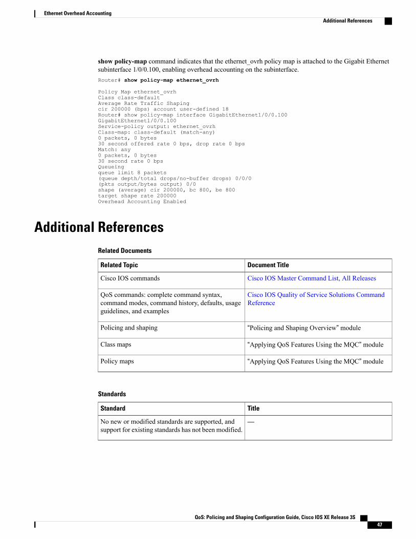
show policy-map command indicates that the ethernet_ovrh policy map is attached to the Gigabit Ethernetsubinterface 1/0/0.100, enabling overhead accounting on the subinterface.Router# show policy-map ethernet_ovrh
Policy Map ethernet_ovrhClass class-defaultAverage Rate Traffic Shapingcir 200000 (bps) account user-defined 18Router# show policy-map interface GigabitEthernet1/0/0.100GigabitEthernet1/0/0.100Service-policy output: ethernet_ovrhClass-map: class-default (match-any)0 packets, 0 bytes30 second offered rate 0 bps, drop rate 0 bpsMatch: any0 packets, 0 bytes30 second rate 0 bpsQueueingqueue limit 8 packets(queue depth/total drops/no-buffer drops) 0/0/0(pkts output/bytes output) 0/0shape (average) cir 200000, bc 800, be 800target shape rate 200000Overhead Accounting Enabled
Additional ReferencesRelated Documents
Document TitleRelated Topic
Cisco IOS Master Command List, All ReleasesCisco IOS commands
Cisco IOS Quality of Service Solutions CommandReference
QoS commands: complete command syntax,command modes, command history, defaults, usageguidelines, and examples
“Policing and Shaping Overview” modulePolicing and shaping
“Applying QoS Features Using the MQC” moduleClass maps
“Applying QoS Features Using the MQC” modulePolicy maps
Standards
TitleStandard
—No new or modified standards are supported, andsupport for existing standards has not been modified.
QoS: Policing and Shaping Configuration Guide, Cisco IOS XE Release 3S 47
Ethernet Overhead AccountingAdditional References

MIBs
MIBs LinkMIB
To locate and downloadMIBs for selected platforms,Cisco IOSXE software releases, and feature sets, useCisco MIB Locator found at the following URL:
http://www.cisco.com/go/mibs
No new or modifiedMIBs are supported, and supportfor existing MIBs has not been modified.
RFCs
TitleRFC
—No new or modified RFCs are supported, and supportfor existing RFCs has not been modified.
Technical Assistance
LinkDescription
http://www.cisco.com/cisco/web/support/index.htmlThe Cisco Support and Documentation websiteprovides online resources to download documentation,software, and tools. Use these resources to install andconfigure the software and to troubleshoot and resolvetechnical issues with Cisco products and technologies.Access to most tools on the Cisco Support andDocumentation website requires a Cisco.com user IDand password.
Feature Information for Ethernet Overhead AccountingThe following table provides release information about the feature or features described in this module. Thistable lists only the software release that introduced support for a given feature in a given software releasetrain. Unless noted otherwise, subsequent releases of that software release train also support that feature.
Use Cisco Feature Navigator to find information about platform support and Cisco software image support.To access Cisco Feature Navigator, go to www.cisco.com/go/cfn. An account on Cisco.com is not required.
QoS: Policing and Shaping Configuration Guide, Cisco IOS XE Release 3S48
Ethernet Overhead AccountingFeature Information for Ethernet Overhead Accounting
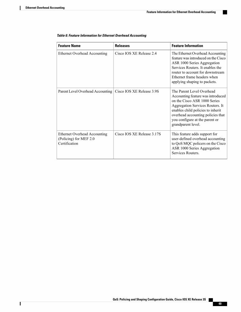
Table 6: Feature Information for Ethernet Overhead Accounting
Feature InformationReleasesFeature Name
The Ethernet OverheadAccountingfeature was introduced on the CiscoASR 1000 Series AggregationServices Routers. It enables therouter to account for downstreamEthernet frame headers whenapplying shaping to packets.
Cisco IOS XE Release 2.4Ethernet Overhead Accounting
The Parent Level OverheadAccounting feature was introducedon the Cisco ASR 1000 SeriesAggregation Services Routers. Itenables child policies to inheritoverhead accounting policies thatyou configure at the parent orgrandparent level.
Cisco IOS XE Release 3.9SParent Level OverheadAccounting
This feature adds support foruser-defined overhead accountingto QoSMQC policers on the CiscoASR 1000 Series AggregationServices Routers.
Cisco IOS XE Release 3.17SEthernet Overhead Accounting(Policing) for MEF 2.0Certification
QoS: Policing and Shaping Configuration Guide, Cisco IOS XE Release 3S 49
Ethernet Overhead AccountingFeature Information for Ethernet Overhead Accounting

QoS: Policing and Shaping Configuration Guide, Cisco IOS XE Release 3S50
Ethernet Overhead AccountingFeature Information for Ethernet Overhead Accounting
C H A P T E R 6MQC Traffic Shaping Overhead Accounting forATM
The MQC Traffic Shaping Overhead Accounting for ATM feature enables a broadband aggregation system(BRAS) to account for various encapsulation types when applying quality of service (QoS) functionality topackets. Typically, in Ethernet digital subscriber line (DSL) environments, the encapsulation from the routerto the digital subscriber line access multiplexer (DSLAM) is Gigabit Ethernet and the encapsulation fromthe DSLAM to the customer premises equipment (CPE) is ATM. ATM overhead accounting enables therouter to account for ATM encapsulation on the subscriber line and for the overhead added by cellsegmentation. This functionality enables the service provider to prevent overruns at the subscriber line andensures that the router executes QoS features on the actual bandwidth used by ATM packets.
• Finding Feature Information, page 51
• Prerequisites for Traffic Shaping Overhead Accounting for ATM, page 52
• Restrictions for Traffic Shaping Overhead Accounting for ATM, page 52
• Information About Traffic Shaping Overhead Accounting for ATM, page 53
• How to Configure Traffic Shaping Overhead Accounting for ATM, page 56
• Configuration Examples for Traffic Shaping Overhead Accounting for ATM, page 60
• Additional References, page 62
• Feature Information for MQC Traffic Shaping Overhead Accounting for ATM, page 63
Finding Feature InformationYour software release may not support all the features documented in this module. For the latest caveats andfeature information, see Bug Search Tool and the release notes for your platform and software release. Tofind information about the features documented in this module, and to see a list of the releases in which eachfeature is supported, see the feature information table at the end of this module.
Use Cisco Feature Navigator to find information about platform support and Cisco software image support.To access Cisco Feature Navigator, go to www.cisco.com/go/cfn. An account on Cisco.com is not required.
QoS: Policing and Shaping Configuration Guide, Cisco IOS XE Release 3S 51
Prerequisites for Traffic Shaping Overhead Accounting for ATMTraffic classes must be configured using the class-map command.
Restrictions for Traffic Shaping Overhead Accounting for ATM• The overhead accounting type or value used within a policy map and between the parent policy mapand the child policy map (in a hierarchical policy map structure) must be consistent.
• You must attach a policy map that is configured with ATM overhead accounting to only an Ethernetinterface (or an IP session on an Ethernet interface).
• Ethernet overhead accounting allows the automatic inclusion of downstream Ethernet frame headers inthe shaped rate.
• If you enable overhead accounting on a child policy, you must enable overhead accounting on the parentpolicy.
• In a policy map, you must either enable overhead accounting for all classes in the policy or disableoverhead accounting for all classes in the policy. You cannot enable overhead accounting for someclasses and disable overhead accounting for other classes in the same policy.
• Overhead accounting is not reflected in any QoS counters (classification, policing, or queuing).
• Implicit ATM overhead accounting for policers are not supported.
• Implicit L2 overhead (ATM or otherwise) for policers are not supported for certain logical targets(tunnels) when the policy is applied to the logical target. The same limitation exists for queuing andscheduling overhead accounting.
• Police overhead cannot be configured on conditional policers (priority and rate), however, the priorityqueue it used will inherit the queueing overhead from parent shaper if configured.
• Police overhead is not added to the counters and are not reflected in statistics reported by the controlplane.
• The overhead accounting type or value used by policing within a policy map and between the parentpolicy map and the child policy map (in a hierarchical policy map structure) must be consistent.
• The overhead accounting type or value used by queuing features within a policy map and between theparent policy map and the child policy map (in a hierarchical policy map structure) must be consistent.
• In releases preceding to Cisco IOS XE Release 3.9S, the router does not support overhead accountingupdates on attached policies and the policy must be detached from the interface before the overhead canbe modified, then the policy can be reattached to the interface.
• The router does not support overhead accounting for classes with fair-queue, which includes the followingscenarios:
◦When used in conjunction with shape in the same class
◦When used in conjunction with bandwidth in the same class
◦When inherited from a parent or grandparent class through the Parent Level Overhead Accountingfeature introduced in Cisco IOS XE Release 3.9S
QoS: Policing and Shaping Configuration Guide, Cisco IOS XE Release 3S52
MQC Traffic Shaping Overhead Accounting for ATMPrerequisites for Traffic Shaping Overhead Accounting for ATM
Information About Traffic Shaping Overhead Accounting forATM
Benefits of Traffic Shaping Overhead Accounting for ATMThe Traffic Shaping Overhead Accounting for ATM feature enables the broadband aggregation system (BRAS)to account for various encapsulation types when applying QoS to packets. Typically, in Ethernet digitalsubscriber line (DSL) environments, the encapsulation from the BRAS to the DSLAM is Gigabit Ethernetand the encapsulation from the DSLAM to the CPE is ATM. ATM overhead accounting enables the BRASto account for ATM encapsulation on the subscriber line and for the overhead added by cell segmentation.This functionality enables the service provider to prevent overruns at the subscriber line and ensures that therouter executes QoS features on the actual bandwidth used by ATM subscriber traffic.
BRAS and Encapsulation TypesBroadband aggregation system (BRAS) uses the encapsulation type that is configured for the DSLAM-CPEside to calculate the ATM overhead per packet.
DSLAM-CPE encapsulation types are based on SubnetworkAccess Protocol (SNAP) andmultiplexer (MUX)formats of ATM adaptation layer 5 (AAL5), followed by routed bridge (RBE), x-1483, x-dot1q-rbe, IP, PPPover Ethernet (PPPoE), or PPP over ATM (PPPoA) encapsulations. Because the DSLAM treats IP and PPPoEpackets as payload, the BRAS does not account for IP and PPPoE encapsulations.
On the BRAS-DSLAM side, encapsulation is IEEE 802.1Q VLAN or Q-in-Q (qinq). However, because theDSLAM removes the BRAS-DSLAM encapsulation, the BRAS does not account for 802.1Q or qinqencapsulation.
AAL5 segmentation processing adds the additional overhead of the 5-byte cell headers, the AAL5 CommonPart Convergence Sublayer (CPCS) padding, and the AAL5 trailer. For more information, see the ATMOverhead Calculation, on page 54.
Subscriber Line Encapsulation TypesThe router supports the following subscriber line encapsulation types:
• snap-rbe
• mux-rbe
• snap-dot1q-rbe
• mux-dot1q-rbe
• snap-pppoa
• mux-pppoa
• snap-1483routed
• mux-1483routed
QoS: Policing and Shaping Configuration Guide, Cisco IOS XE Release 3S 53
MQC Traffic Shaping Overhead Accounting for ATMInformation About Traffic Shaping Overhead Accounting for ATM
• snap-rbe-dot1q
• mux-rbe-dot1q
The encapsulation types listed above are for AAL5, qinq, and dot1q encapsulations. User-definedencapsulations with offsets based on the platform in use are also supported.
Note
ATM Overhead CalculationThe Traffic Shaping Overhead Accounting for ATM feature prevents oversubscription of a subscriber lineby accounting for the ATM encapsulation overhead at the BRAS. When calculating the ATM overhead, theTraffic Shaping Overhead Accounting for ATM feature considers the following:
• The encapsulation type used by the BRAS
• The CPCS trailer overhead
• The encapsulation type used between the DSLAM and the CPE
The offset size (a parameter used to calculate ATM overhead accounting) is calculated using the followingformula:
Offset size in bytes = (CPCS trailer overhead) + (DSLAM to CPE) - (BRAS encapsulation type)
See the table below for the offset sizes, in bytes, derived from this formula.
This offset size, along with the packet size and packet assembler/disassembler (PAD) byte overhead in theCPCS, is used by the router to calculate the ATM overhead accounting rate.
A CPCS trailer overhead of 8 bytes corresponds to AAL5. A CPCS trailer overhead of 4 bytes correspondsto AAL3, but AAL3 is not supported.
Note
Table 7: Offset Sizes, in Bytes, Used for ATM Overhead Calculation
Offset SizeDSLAM to CPECPCS Trailer OverheadBRASEncapsulation Type inUse
-73818dot1q mux-1483routed
-46818dot1q snap-1483routed
414818dot1q mux-rbe
1424818dot1q snap-rbe
818818dot1q mux-dot1q-rbe
1828818dot1q snap-dot1q-rbe
QoS: Policing and Shaping Configuration Guide, Cisco IOS XE Release 3S54
MQC Traffic Shaping Overhead Accounting for ATMATM Overhead Calculation

Offset SizeDSLAM to CPECPCS Trailer OverheadBRASEncapsulation Type inUse
-142818 + 6qot1q mux-pppoa
-124818 + 6qot1q snap-pppoa
-113822qinq mux-1483routed
-86822qinq snap-1483routed
014822qinq mux-rbe
1024822qinq snap-rbe
418822qinq mux-dot1q-rbe
1428822qing snap-dot1q-rbe
-182822 + 6qinq mux-pppoa
-164822 + 6qinq snap-pppoa
ATM Overhead Accounting and Hierarchical PoliciesIn hierarchical policies, you can enable ATM overhead accounting for shaping and bandwidth on parentpolicies and child policies. You are not required to enable ATM overhead accounting on a traffic class thatdoes not contain the bandwidth or shape command. If you enable ATM overhead accounting on a childpolicy, then you must enable ATM overhead accounting on the parent policy. The parent and child classesmust specify the same encapsulation type when ATM overhead accounting is enabled.
Overhead Accounting and Priority QueuesOverhead accounting configuration is supported for queuing features (shape, bandwidth and priority) andnon-queuing feature (police) separately. However, priority queue can be integrated with policer.When overheadaccounting is configured on a priority queue, through inheritance, it operates in the following fashion:
• Overhead accounting is added to (or subtracted from) the priority packet for queuing features in thehierarchy (for example, shape in the parent class).
• Overhead accounting is not added to the packet for priority rate enforcement (priority {bandwidth-kbps| percent percentage} [burst]). Although policing overhead accounting is supported, it does not applyto the conditional policer (rate enforcement is implemented through this conditional policer).
QoS: Policing and Shaping Configuration Guide, Cisco IOS XE Release 3S 55
MQC Traffic Shaping Overhead Accounting for ATMATM Overhead Accounting and Hierarchical Policies

How to Configure Traffic Shaping Overhead Accounting forATM
Configuring Traffic Shaping Overhead Accounting for ATM in a HierarchicalPolicy
SUMMARY STEPS
1. enable2. configure terminal3. policy-map policy-map-name4. class class-map-name5. bandwidth {bandwidth-kbps | percent percentage | remaining percent percentage} account {{qinq | dot1q}
{aal5 | aal3} {subscriber-encapsulation}} | {user-defined offset [atm]}}6. bandwidth remaining ratio ratio [account {qinq | dot1q} [aal5|aal3] {subscriber-encapsulation |
user-definedoffset[atm]}]7. shape [average |peak] mean-rate[burst-size] [excess-burst-size] account {{{qinq | dot1q} {aal5 | aal3}
{subscriber-encapsulation}} | {user-defined offset [atm]}}8. end
DETAILED STEPS
PurposeCommand or Action
Enables privileged EXEC mode.enableStep 1
Example:
Router> enable
• Enter your password if prompted.
Enters global configuration mode.configure terminal
Example:
Router# configure terminal
Step 2
Creates or modifies the child policy and enters policy-map configuration mode.policy-map policy-map-nameStep 3
Example:
Router(config)# policy-mapBusiness
• Enter the policy map name. This is the name of the child policy.
QoS: Policing and Shaping Configuration Guide, Cisco IOS XE Release 3S56
MQC Traffic Shaping Overhead Accounting for ATMHow to Configure Traffic Shaping Overhead Accounting for ATM

PurposeCommand or Action
Assigns the traffic class that you specify for the policy map and enters policy-mapclass configuration mode.
class class-map-name
Example:
Router(config-pmap)# classvideo
Step 4
• Enter the traffic class name. This is the name of the previously configured classmap.
Enables Class-BasedWeighted Fair Queueing (CBWFQ) on the basis of the keywordsand arguments specified, such as the following:
bandwidth {bandwidth-kbps |percent percentage | remaining
Step 5
percent percentage} account {{qinq• bandwidth-kbps --Specifies or modifies the minimum bandwidth allocated for aclass that belongs to a policy map. Valid values are from 8 to 2488320, whichrepresents from 1 to 99 percent of the link bandwidth.
| dot1q} {aal5 | aal3}{subscriber-encapsulation}} |{user-defined offset [atm]}}
Example:
Router(config-pmap-c)#
• percent percentage --Specifies or modifies the minimum percentage of the linkbandwidth allocated for a class that belongs to a policy map. Valid values arefrom 1 to 99.
bandwidth 8000 account dot1qaal5 snap-pppoa
• remaining percent percentage --Specifies or modifies the minimum percentageof unused link bandwidth allocated for a class that belongs to a policy map. Validvalues are from 1 to 99.
• account --Enables ATM overhead accounting.
• qinq --Specifies queue-in-queue encapsulation as the BRAS-DSLAMencapsulation type.
• dot1q --Specifies IEEE 802.1Q VLAN encapsulation as the BRAS-DSLAMencapsulation type.
• aal5 --Specifies the ATM adaptation layer 5 that supports connection-orientedvariable bit rate (VBR) services.
• aal3 --Specifies the ATM adaptation layer 5 that supports both connectionlessand connection-oriented links.
• subscriber-encapsulation --Specifies the encapsulation type at the subscriberline. For more information, see the Subscriber Line Encapsulation Types, onpage 53.
• user-defined --Specifies the offset size that the router uses when calculating theATM overhead.
• offset --Specifies the offset size when calculating ATM overhead. Valid valuesare from -63 to +63 bytes.
• atm --(Optional) Applies the ATM cell tax in the ATM overhead calculation.
(Optional) Specifies the bandwidth-remaining ratio for the subinterface along withATM accounting parameters:
bandwidth remaining ratio ratio[account {qinq | dot1q} [aal5|aal3]
Step 6
{subscriber-encapsulation |user-definedoffset[atm]}] • ratio --Specifies the bandwidth-remaining ratio for the subinterface. Valid values
are 1 to 100. The default value is 1.
QoS: Policing and Shaping Configuration Guide, Cisco IOS XE Release 3S 57
MQC Traffic Shaping Overhead Accounting for ATMConfiguring Traffic Shaping Overhead Accounting for ATM in a Hierarchical Policy
PurposeCommand or Action
Example:
Router(config-pmap-c)#
For the Cisco 7600 series router, valid values are from 1 to 10000. The defaultvalue is 1.
Note
• account --Enables ATM overhead accounting.bandwidth remaining ratio 10account dot1q aal5 snap-pppo • qinq --Specifies queue-in-queue encapsulation as the BRAS-DSLAM
encapsulation type.
• dot1q --Specifies IEEE 802.1Q VLAN encapsulation as the BRAS-DSLAMencapsulation type.
• aal5 --Specifies the ATM adaptation layer 5 that supports connection-orientedVBR services.
• aal3 --Specifies the ATM adaptation layer 5 that supports both connectionlessand connection-oriented links.
• subscriber-encapsulation --Specifies the encapsulation type at the subscriberline. For more information, see the Subscriber Line Encapsulation Types, onpage 53.
• user-defined --Specifies the offset size that the router uses when calculating theATM overhead.
• offset --Specifies the offset size, in bytes, when calculating ATM overhead. Validvalues are from -63 to +63.
• atm --(Optional) Applies the ATM cell tax in the ATM overhead calculation.
Shapes traffic to the indicated bit rate and enables ATM overhead accounting on thebasis of the keywords and arguments specified, such as the following:
shape [average |peak]mean-rate[burst-size]
Step 7
[excess-burst-size] account {{{qinq• average --(Optional) The committed burst (Bc) that specifies the maximumnumber of bits sent out in each interval.
| dot1q} {aal5 | aal3}{subscriber-encapsulation}} |{user-defined offset [atm]}} • peak --(Optional) Specifies the maximum number of bits sent out in each interval
(the Bc + excess burst [Be]). The Cisco 10000 router and the SIP400 (on theCisco 7600 series router) do not support this option.Example:
Router(config-pmap-c)# shape • mean-rate --Also called committed information rate (CIR). Indicates the bit rateused to shape the traffic, in bits per second.8000 account qinq aal5
snap-dot1q-rbe
• burst-size --(Optional) The number of bits in a measurement interval (Bc).
• excess-burst-size --(Optional) The acceptable number of bits permitted to go overthe Be.
• account --Enables ATM overhead accounting.
• qinq --Specifies queue-in-queue encapsulation as the BRAS-DSLAMencapsulation type.
• dot1q --Specifies IEEE 802.1Q VLAN encapsulation as the BRAS-DSLAMencapsulation type.
QoS: Policing and Shaping Configuration Guide, Cisco IOS XE Release 3S58
MQC Traffic Shaping Overhead Accounting for ATMConfiguring Traffic Shaping Overhead Accounting for ATM in a Hierarchical Policy
PurposeCommand or Action
• aal5 --The ATM adaptation layer 5 that supports connection-oriented variablebit rate (VBR) services.
• aal3 --Specifies the ATM Adaptation Layer 5 that supports both connectionlessand connection-oriented links. You must specify either aal3 or aal5.
• subscriber-encapsulation --Specifies the encapsulation type at the subscriberline. For more information, see the Subscriber Line Encapsulation Types, onpage 53.
• user-defined --Specifies the offset size that the router uses when calculating theATM overhead.
• offset --Specifies the offset size when calculating ATM overhead. Valid valuesare from -63 to +63 bytes.
• atm --(Optional) Applies ATM cell tax in the ATM overhead calculation.Configuring both the offset and the atm options adjusts the packet size to theoffset size and then adds ATM cell tax.
Exits policy-map class configuration mode and returns to privileged EXEC mode.end
Example:
Router(config-pmap-c)# end
Step 8
Verifying the Configuration of Traffic Shaping Overhead Accounting for ATM
SUMMARY STEPS
1. enable2. show policy-map [policy-map-name]3. show policy-map session4. show running-config5. exit
DETAILED STEPS
PurposeCommand or Action
Enables privileged EXEC mode.enableStep 1
Example:
Router> enable
• Enter your password if prompted.
QoS: Policing and Shaping Configuration Guide, Cisco IOS XE Release 3S 59
MQC Traffic Shaping Overhead Accounting for ATMVerifying the Configuration of Traffic Shaping Overhead Accounting for ATM

PurposeCommand or Action
(Optional) Displays the configuration of all classes for aspecified policy map or of all classes for all existing policymaps.
show policy-map [policy-map-name]
Example:
Router# show policy-map unit-test
Step 2
• (Optional) Enter the policy map name.
(Optional) Displays the QoS policy map in effect for anIPoE/PPPoE session.
show policy-map session
Example:
Router# show policy-map session
Step 3
(Optional) Displays the contents of the currently runningconfiguration file.
show running-config
Example:
Router# show running-config
Step 4
Exits privileged EXEC mode.exit
Example:
Router# exit
Step 5
Configuration Examples for Traffic Shaping OverheadAccounting for ATM
Example Enabling Traffic Shaping Overhead Accounting for ATMThe following example shows how to enable ATM overhead accounting using a hierarchical policy mapstructure. The Child policy map has two classes: Business and Non-Business. The Business class has priorityand is policed at 128,000 kbps. The Non-Business class has ATM overhead accounting enabled and has abandwidth of 20 percent of the available bandwidth. The Parent policy map shapes the aggregate traffic to256,000 kbps and enables ATM overhead accounting.
Notice that Layer 2 overhead accounting is not explicitly configured for the Business traffic class. If theclass-default class of a parent policy has ATM overhead accounting enabled, you are not required to enableATM overhead accounting on a child traffic class that does not contain the bandwidth or shape command.Therefore, in this example, the Business priority queue implicitly has ATM overhead accounting enabledbecause its parent class-default class has overhead accounting enabled.policy-map Childclass Businessprioritypolice 128000class Non-Business
QoS: Policing and Shaping Configuration Guide, Cisco IOS XE Release 3S60
MQC Traffic Shaping Overhead Accounting for ATMConfiguration Examples for Traffic Shaping Overhead Accounting for ATM

bandwidth percent 20 account dot1q aal5 snap-rbe-dot1qexitexitpolicy-map Parentclass class-defaultshape 256000 account dot1q aal5 snap-rbe-dot1qservice-policy Child
In the following example, overhead accounting is enabled for bandwidth on the gaming and class-defaultclass of the child policy map named subscriber_classes and on the class-default class of the parent policy mapnamed subscriber_line. The voip and video classes do not have accounting explicitly enabled; these classeshave ATM overhead accounting implicitly enabled because the parent policy has overhead accounting enabled.Notice that the features in the parent and child policies use the same encapsulation type.
policy-map subscriber_classesclass voippriority level 1police 8000class videopriority level 2police 8000class gamingbandwidth remaining percent 80 account dot1q aal5 snap-rbe-dot1qclass class-defaultbandwidth remaining percent 20 account dot1q aal5 snap-rbe-dot1q
policy-map subscriber_lineclass class-defaultbandwidth remaining ratio 10 account dot1q aal5 snap-rbe-dot1qshape average 512 account aal5 dot1q snap-rbe-dot1qservice policy subscriber_classes
Example Verifying Traffic Shaping Overhead Accounting for ATM
Router# show policy-map interface
Service-policy output:unit-testClass-map: class-default (match-any)100 packets, 1000 bytes30 second offered rate 800 bps, drop rate 0 bpsMatch: anyshape (average) cir 154400, bc 7720, be 7720target shape rate 154400overhead accounting: enabledbandwidth 30% (463 kbps)overhead accounting: disabledqueue limit 64 packets(queue depth/total drops/no-buffer drops) 0/0/0(packets output/bytes output) 100/1000
Router# show policy-map session output
SSS session identifier 2 -Service-policy output: ATM_OH_POLICY
Class-map: class-default (match-any)0 packets, 0 bytes30 second offered rate 0 bps, drop rate 0 bpsMatch: anyQueueingqueue limit 2500 packets(queue depth/total drops/no-buffer drops) 0/0/0(pkts output/bytes output) 0/0shape (average) cir 10000000, bc 40000, be 40000target shape rate 10000000Overhead Accounting Enabled
QoS: Policing and Shaping Configuration Guide, Cisco IOS XE Release 3S 61
MQC Traffic Shaping Overhead Accounting for ATMExample Verifying Traffic Shaping Overhead Accounting for ATM

The following output from the show running-config command indicates that ATM overhead accounting isenabled for shaping. The BRAS-DSLAM encapsulation is dot1q and the subscriber line encapsulation issnap-rbe based on the AAL5 service.
subscriber policy recording rules limit 64no mpls traffic-eng auto-bw timers frequency 0call rsvp-sync!controller T1 2/0framing sflinecode ami!controller T1 2/1framing sflinecode ami!!policy-map unit-testclass class-defaultshape average percent 10 account dot1q aal5 snap-rbe!
Additional ReferencesRelated Documents
Document TitleRelated Topic
Cisco IOS Quality of Service Solutions CommandReference
QoS commands: complete command syntax,command modes, command history, defaults, usageguidelines, and examples
"Applying QoS Features Using the MQC" moduleModular Quality of Service (QoS) Command-LineInterface (CLI) (MQC), hierarchical policies, policymaps
"Policing and Shaping Overview" modulePolicing and shaping traffic
Standards
TitleStandard
--No new or modified standards are supported by thisfeature, and support for existing standards has notbeen modified by this feature.
QoS: Policing and Shaping Configuration Guide, Cisco IOS XE Release 3S62
MQC Traffic Shaping Overhead Accounting for ATMAdditional References
MIBs
MIBs LinkMIB
To locate and downloadMIBs for selected platforms,Cisco IOSXE software releases, and feature sets, useCisco MIB Locator found at the following URL:
http://www.cisco.com/go/mibs
No new or modified MIBs are supported by thisfeature, and support for existing MIBs has not beenmodified by this feature.
RFCs
TitleRFC
--No new or modified RFCs are supported by thisfeature, and support for existing RFCs has not beenmodified by this feature.
Technical Assistance
LinkDescription
http://www.cisco.com/cisco/web/support/index.htmlThe Cisco Support and Documentation websiteprovides online resources to download documentation,software, and tools. Use these resources to install andconfigure the software and to troubleshoot and resolvetechnical issues with Cisco products and technologies.Access to most tools on the Cisco Support andDocumentation website requires a Cisco.com user IDand password.
Feature Information for MQC Traffic Shaping OverheadAccounting for ATM
The following table provides release information about the feature or features described in this module. Thistable lists only the software release that introduced support for a given feature in a given software releasetrain. Unless noted otherwise, subsequent releases of that software release train also support that feature.
Use Cisco Feature Navigator to find information about platform support and Cisco software image support.To access Cisco Feature Navigator, go to www.cisco.com/go/cfn. An account on Cisco.com is not required.
QoS: Policing and Shaping Configuration Guide, Cisco IOS XE Release 3S 63
MQC Traffic Shaping Overhead Accounting for ATMFeature Information for MQC Traffic Shaping Overhead Accounting for ATM
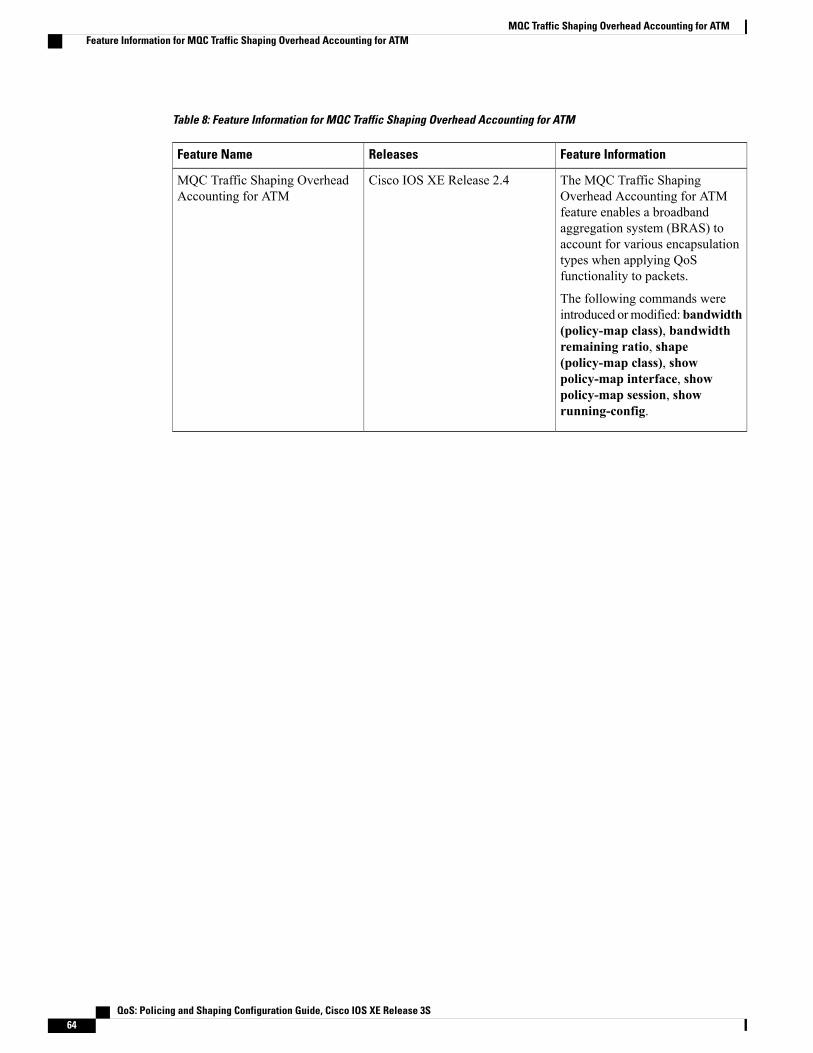
Table 8: Feature Information for MQC Traffic Shaping Overhead Accounting for ATM
Feature InformationReleasesFeature Name
The MQC Traffic ShapingOverhead Accounting for ATMfeature enables a broadbandaggregation system (BRAS) toaccount for various encapsulationtypes when applying QoSfunctionality to packets.
The following commands wereintroduced ormodified:bandwidth(policy-map class), bandwidthremaining ratio, shape(policy-map class), showpolicy-map interface, showpolicy-map session, showrunning-config.
Cisco IOS XE Release 2.4MQC Traffic Shaping OverheadAccounting for ATM
QoS: Policing and Shaping Configuration Guide, Cisco IOS XE Release 3S64
MQC Traffic Shaping Overhead Accounting for ATMFeature Information for MQC Traffic Shaping Overhead Accounting for ATM
C H A P T E R 7QoS Policy Accounting
The QoS Policy Accounting feature helps you accurately account for traffic on your system. It also providesgreater flexibility in assigning quality of service (QoS) configurations to subscribers. In addition, the QoSAccounting High Availability feature ensures that QoS accounting statistics persist, and that the RADIUSaccounting billing server continues to report accounting counters during planned and unexpected RouteProcessor (RP) switchovers. This module describes how to configure QoS policy accounting, use subscribertemplates, and activate subscriber accounting accuracy.
• Finding Feature Information, page 65
• Prerequisites for QoS Policy Accounting, page 65
• Restrictions for QoS Policy Accounting, page 66
• Information About QoS Policy Accounting, page 68
• How to Use QoS Policy Accounting, page 86
• Configuration Examples for QoS Policy Accounting, page 91
• Additional References, page 91
• Feature Information for the QoS Policy Accounting Feature, page 92
Finding Feature InformationYour software release may not support all the features documented in this module. For the latest caveats andfeature information, see Bug Search Tool and the release notes for your platform and software release. Tofind information about the features documented in this module, and to see a list of the releases in which eachfeature is supported, see the feature information table at the end of this module.
Use Cisco Feature Navigator to find information about platform support and Cisco software image support.To access Cisco Feature Navigator, go to www.cisco.com/go/cfn. An account on Cisco.com is not required.
Prerequisites for QoS Policy Accounting• PPP over Ethernet (PPPoE) or PPP over Ethernet over ATM (PPPoEoA) sessions are enabled.
QoS: Policing and Shaping Configuration Guide, Cisco IOS XE Release 3S 65

• The RADIUS server is configured.
• Authentication, authorization, and accounting (AAA) is enabled.
• The subscriber’s user profile on the RADIUS server has been created.
• A policy map is configured.
• A service template is configured.
• Traffic classes have been created.
• Stateful switchover (SSO) and In-service Software Upgrade (ISSU) prerequisites must be met. For moreinformation, see the Cisco IOS High Availability Configuration Guide.
Restrictions for QoS Policy Accounting• In system failover, the following occurs:
• For QoS accounting configured statically at the policy map, QoS accounting statistics are reset tozero.
• For QoS accounting configured dynamically using service templates, sessions no longer exist onthe new active Route Processor (RP).
In Cisco IOS XE Release 3.5S and later releases, high availability (HA) support isavailable for accounting services enabled through a service template. Therefore, QoSaccounting statistics and service sessions are preserved during a system failover and areavailable on the new active RP.
Note
• Multicasting is not supported for QoS policy accounting services.
• The following QoS actions are not supported in service templates:
• account
• fair-queue
• netflow-sampler
• random-detect
• The following QoS filters are not supported in service templates:
• atm
• class-map
• cos
• destination-address
• discard-class
• fr-de
QoS: Policing and Shaping Configuration Guide, Cisco IOS XE Release 3S66
QoS Policy AccountingRestrictions for QoS Policy Accounting

• fr-dlci
• input-interface
• mpls
• not
• packet
• source-address
• vlan
• Service template definition lines may not exceed maximum configuration line length allowed by theCisco IOS CLI. You may need to shorten shell variable names to stay within this limit.
• A template service activated on a session cannot be changed. Instead, you can deactivate it and activatea different template service.
•When a template service is active, a legacy complex parameterized string may not be used to changethe QoS policy active on a session.
• IP address parameterization is supported only for IPv4 and only for named ACLs without remarks. IPaddresses specified in the parameterized service activation are always added to the cloned ACL in thisfixed pattern: "permit ip network mask any" and "permit ip any network mask".
• Service templates are supported only for PPP sessions and may not be activated on subinterfaces.
• Only one turbo button service can be active on a session at any given time. Turbo button service is anyservice that changes a QoS action other than “service-policy xxxx” (changing the child policy) in theclass-default of the parent policy.
• Shell variables, QoS class map, and Access Control List (ACL) names may not have the followingcharacters:
• !
• $
• #
• -
• ,
• >
• <
• Service names are echoed back in the accounting records only for group accounting (when you use$_acctgrp in the service template).
• The IN/OUTQoS policy name active on a session is formed by concatenating the previously active QoSpolicy (or the static QoS policy specified in the last multiservice Change of Authorization (CoA) orAccess-Accept).
• Two template services instantiated from the same service template may not be activated on the sessionat the same time. However, multiple template services instantiated from unrelated service templates canbe active on a session at the same time.
QoS: Policing and Shaping Configuration Guide, Cisco IOS XE Release 3S 67
QoS Policy AccountingRestrictions for QoS Policy Accounting
• Template service support is available only for locally terminated PPP and PPP forwarded sessions onthe Layer 2 Tunneling Protocol (L2TP) Access Concentrator (LAC).
• For PPP forwarded sessions on the LAC, to apply template services via Access-Accept, use the followingconfigurations:
• vpdn authen-before-forward.
• Specify template services only in the user authorization profile (Access-Accept that is receivedafter PPP authentication), not in the authentication profile.
• Only activate template services on the child policy under the parent class-default (only two levels) andon the parent policy (Turbo Button service).
• The default QoS policy can be only two levels deep (Parent + Child under class-default) and should nothave a child policy configured under any class other than the class-default.
• A child policy should be configured under the default parent policy class-default in order for templateservices to be activated at the child level.
• Only rollback due to syntax error checking is supported.
•When multiple service activations or deactivations are included in a single CoA message, the failure ofany operation (activation or deactivation)means that the CoAmust roll back (undo) all previous operationsto restore the session state to what it was before the CoA processing started. In other words, either allthe operations must be processed successfully in a CoA or none at all. A CoA negative ACK (NACK)is sent to the RADIUS.
• For rollback to work during Access-Accept processing, subscriber service multiple-accept processingmust be configured. The failure to process a service in an Access-Accept should roll back (undo) allprevious services in the Access-Accept. The session will come up even if Access-Accept serviceprocessing fails.
• Errors originating in the platform or data plane will not trigger rollback which can result in an incompleteservice.
• Do not modify a service template if its template services are in use or active on sessions. Use the showsubscriber policy ppm-shim-db command to display which template services are in use.
Information About QoS Policy AccountingRADIUS is a networking protocol that provides AAA management. Among other things, each RADIUSaccounting message includes ingress and egress counters. The QoS Policy Accounting feature helps youresolve any inaccuracies between counters.
QoS Policy Accounting Feature in GroupsThe QoS Policy Accounting feature collects and reports the following information to the RADIUS serverper-session:
• Acct-Session-Id
• Ingress and egress packets/bytes/gigawords, packets, and bytes of successfully transmitted packets
QoS: Policing and Shaping Configuration Guide, Cisco IOS XE Release 3S68
QoS Policy AccountingInformation About QoS Policy Accounting
• Parent-Session-Id
• Policy name and class or group name (if the QoS Policy Accounting feature is enabled on the group)
• Service name
• Username
When you enable the QoS Policy Accounting feature on a group and assign it a group name, this featureaggregates packets that meet the following criteria:
• Classified by traffic classes in the same group
• Included in the ingress or egress QoS policy applied on the same target
Separate Accounting StreamsIf you do not assign a traffic class to a group, but instead assign it to an AAAmethod list, separate QoS policyaccounting streams are created for each traffic class. Separate accounting streams allow you to differentiatebetween traffic that matches more than one class. Each unique target, direction, policy name, and class namehas a unique RADIUS Acct-Session-Id value.
Service TemplatesService templates allow you to dynamically change QoS parameters without defining a new QoS policy onthe CLI. You can change QoS policy when a session begins or any time after the session is established. Beforeyou dynamically modify an active QoS deactivate the current service.
To understand service templates, learn the following terms:
• Service templates:
• Are Cisco IOS shell functions
• Have IN QoS policy-map definitions
• Have OUT QoS policy-map definitions
• Are programmatically invoked
• Specify default values for shell variables
• Template services:
• Are QoS service names with a parenthesis in them
• Have a matching shell-map template definition
• Are created dynamically during service template shell function execution
• IN Net effect policy map
• OUT Net effect policy map
QoS: Policing and Shaping Configuration Guide, Cisco IOS XE Release 3S 69
QoS Policy AccountingSeparate Accounting Streams

The QoS Policy Accounting feature, describes how the Cisco IOS shell overrides default values of variablesused in service template shell functions. QoS policy definitions inside a shell map may have shell variablesin place of QoS action parameter values.
Using Service TemplatesTo create a service template, you write the service template in a text editor and you then copy the template tothe CLI. The contents of a shell map block are treated as text.
When you define the service-template policy maps (policy map $_outgoing/$_incoming), there is no CLI helpor prompts available. For example you cannot access the following CLI aids:
• Parser auto completion
• Command options
• Range help
• Syntax checking
There is no editor available to you in the CLI, if you make a mistake you must delete the entire servicetemplate and then configure it again from the start.
Note
Verifying Service Templates
When you write a service template in a text editor you do not have a syntax checking facility. Therefore,before you activate your service template, you must verify its syntax. The following code sample shows howto verify the voice-service1 service template. To verify your own template, replace voice-service1 with yourservice template name.
(shell map voice-service1 police_rate=100000 prec_value=4 queue_size=1)configure terminalno policy-map test-svc_IN <-------- Removes previous service template verifications.no policy-map test-svc_OUT <-------- Removes previous service template verifications.no aaa-accounting group test_svc_GRP <-------- Removes previous service templateverifications.endtrigger voice-service1 _incoming=test-svc_IN _outgoing=test-svc_OUT _acctgrp=test-svc_GRPshow policy-map test-svc-IN <--------Ensure that the output matches the expected service template template service with defaultvalues.show policy-map test-svc-OUT <--------Ensure that the output matches the expected service template template service with defaultvalues.
Removing Service Templates
To remove a service template, at the command line enter:
no shell map voice-service1 police_rate=100000 prec_value=4 queue_size=1 in_h=class-defaultout_h=class-defaultWhere voice-service1 is the name of your service template.
QoS: Policing and Shaping Configuration Guide, Cisco IOS XE Release 3S70
QoS Policy AccountingService Templates
Sample Service Templates
Service Template
This example shows a sample service template:
{configure terminalaccounting group $_acctgrp list defaultpolicy-map $_outgoingclass voippolice $police_rate 60625 0 conform-action transmit exceed-action drop violate-action
dropexit
priority level 1queue-limit 8 packetsset precedence $prec_valueset cos 6aaa-accounting group $_acctgrp
class voip-controlpolice 112000 1000 0 conform-action transmit exceed-action drop violate-action drop
queue-limit $queue_size packetsset precedence 6aaa-accounting group $_acctgrp
policy-map $_incomingclass voippolice 200000 9216 0 conform-action transmit exceed-action transmit violate-action
dropset precedence 5aaa-accounting group $_acctgrp
class voip-controlpolice 112000 21000 0 conform-action transmit exceed-action transmit violate-action
dropset precedence 7aaa-accounting group $_acctgrp
}
Action Parameter Override
Action Parameter Override is a type of service template where shell variables are used in place of parametersfor QoS actions such as police, shape, and bandwidth, configurations entered under a class in a QoS policy.
If you deactivate a template service, the system restores the previously active QoS policy. The QoS policynamemay be different but is structurally and functionally identical to the QoS policy active before the templateservice was activated.
This example generates the service with the following parameters:
Reserved variable initialization before executing the service template shell function:$_incoming = voice-service1>police_rate=200000#prec_value=5#queue_size=32<_IN$_outgoing = voice-service1>police_rate=200000#prec_value=5#queue_size=32<_OUT$_acctgrp = aaa-accounting groupvoice-service1>police_rate=200000#prec_value=5#queue_size=32<_GRP list defaultOUT QoS policy active on the session:
policy-map output_parentclass class-defaultshape average 10000000service-policy output_child
policy-map output_childclass class-default
QoS: Policing and Shaping Configuration Guide, Cisco IOS XE Release 3S 71
QoS Policy AccountingService Templates

IN QoS policy active on the session:
policy-map input_parentclass class-defaultpolice 10000000service-policy input_child
policy-map input_childclass-defaultAfter you activate voice-service1(police_rate=200000,prec_value=5,queue_size=32) on the target session,this is the active OUT policy:
policy-mapoutput_parent$class-default$voice-service1>police_rate=200000#prec_value=5#queue_size=32<_OUT$class-default
class class-defaultshape average 10000000service-policy
output_child$voice-service1>police_rate=200000#prec_value=5#queue_size=32<_OUT$class-defaultpolicy-mapoutput_child$voice-service1>police_rate=200000#prec_value=5#queue_size=32<_OUT$class-default
class voippolice 200000 60625 0 conform-action transmit exceed-action drop violate-action
droppriority level 1queue-limit 8 packetsset precedence 5set cos 6
aaa-accounting group voice-service1>police_rate=200000#prec_value=5#queue_size=32<_GRP
class voip-controlpolice 112000 1000 0 conform-action transmit exceed-action drop violate-action drop
queue-limit 32 packetsset precedence 6
aaa-accounting group voice-service1>police_rate=200000#prec_value=5#queue_size=32<_GRPclass class-defaultAfter you activate voice-service1(police_rate=200000,prec_value=5,queue_size=32) on the target session,this is the active IN policy:
policy-mapinput_parent$class-default$voice-service1>police_rate=200000#prec_value=5#queue_size=32<_IN$class-default
class class-defaultpolice cir 10000000 bc 312500 conform-action transmit exceed-action dropservice-policy
input_child$voice-service1>police_rate=200000#prec_value=5#queue_size=32<_IN$class-defaultpolicy-mapinput_child$voice-service1>police_rate=200000#prec_value=5#queue_size=32<_IN$class-default
class voippolice 200000 9216 0 conform-action transmit exceed-action transmit violate-action
dropset precedence 5
aaa-accounting group voice-service1>police_rate=200000#prec_value=5#queue_size=32<_GRP
class voip-controlpolice 112000 21000 0 conform-action transmit exceed-action transmit violate-action
dropset precedence 7
aaa-accounting group voice-service1>police_rate=200000#prec_value=5#queue_size=32<_GRP
class-default
QoS: Policing and Shaping Configuration Guide, Cisco IOS XE Release 3S72
QoS Policy AccountingService Templates
Action Parameterization Default Parameters
Action Parameterization Default Paramters is a type of service template where shell variables are used inplace of parameters for QoS actions such as police, shape, and bandwidth, configurations entered under aclass in a QoS policy.
If you deactivate a template service, the system restores the previously active QoS policy. The QoS policynamemaybe different but is structurally and functionally identical to the QoS policy active before the templateservice was activated.
OUT QoS policy active on the session:
policy-map output_parentclass class-default
shape average 10000000service-policy output_child
policy-map output_childclass class-defaultIN QoS policy active on the session:policy-map input_parentclass class-defaultpolice 10000000service-policy input_child
policy-map input_childclass-defaultip access-list extended voip-aclpermit ip 10.1.1.0 0.0.0.255 anyip access-list extended voip-control-aclpermit ip 10.2.2.0 0.0.0.255 anyclass-map match-any voipmatch access-group name voip-acl!class-map match-any voip-controlmatch access-group name voip-control-acl!shell map voice-service1 police_rate=100000 prec_value=4 queue_size=1 in_h=class-defaultout_h=class-default{
configure terminalaccounting group $_acctgrp list defaultpolicy-map $_outgoingclass voippolice $police_rate 60625 0 conform-action transmit exceed-action drop violate-action
dropexit
priority level 1queue-limit 8 packetsset precedence $prec_valueset cos 6aaa-accounting group $_acctgrp
class voip-controlpolice 112000 1000 0 conform-action transmit exceed-action drop violate-action drop
queue-limit $queue_size packetsset precedence 6aaa-accounting group $_acctgrp
policy-map $_incomingclass voippolice 200000 9216 0 conform-action transmit exceed-action transmit violate-action
dropset precedence 5aaa-accounting group $_acctgrp
class voip-controlpolice 112000 21000 0 conform-action transmit exceed-action transmit violate-action
dropset precedence 7aaa-accounting group $_acctgrp
}
QoS: Policing and Shaping Configuration Guide, Cisco IOS XE Release 3S 73
QoS Policy AccountingService Templates

After you activate voice-service1 on the target session, this is the active OUT policy:policy-map output_parent$class-default$voice-service1><_OUT$class-default classclass-defaultshape average 10000000service-policy output_child$voice-service1><_OUT$class-default
policy-map output_child$voice-service1><_OUT$class-defaultclass voippolice 10000 60625 0 conform-action transmit exceed-action drop violate-action droppriority level 1queue-limit 8 packetsset precedence 4set cos 6aaa-accounting group voice-service1><_GRPclass voip-controlpolice 112000 1000 0 conform-action transmit exceed-action drop violate-action dropqueue-limit 16 packetsset precedence 6aaa-accounting group voice-service1><GRP
class class-defaultAfter you activate voice-service1 on the target session, this is the active IN policy:policy-map input_parent$class-default$voice-service1><_IN$class-defaultclass class-defaultpolice cir 10000000 bc 312500 conform-action transmit exceed-action dropservice-policy input_child$voice-service1><_IN$class-defaultpolicy-map input_child$voice-service1><_IN$class-defaultclass voippolice 200000 9216 0 conform-action transmit exceed-action transmit violate-action dropset precedence 5aaa-accounting group voice-service1><_GRPclass voip-controlpolice 112000 21000 0 conform-action transmit exceed-action transmit violate-action dropset precedence 7aaa-accounting group voice-service1><_GRPclass-default
Class Name Override
Class name override is a type of service template where shell variables are used in place of parameters forQoS actions such as police, shape, and bandwidth, configurations entered under a class in a QoS policy. Shellvariables may also be used in place of class names in service template policy definitions. Shell variables maycompletely substitute a class name or may be configured as a variable suffix with a constant prefix.
If you deactivate a template service, the system restores the previously active QoS policy. The QoS policynamemay be different but is structurally and functionally identical to the QoS policy active before the templateservice was activated.
OUT QoS policy active on the session:policy-map output_parentclass class-defaultshape average 10000000service-policy output_child
policy-map output_childclass class-defaultIN QoS policy active on the session:policy-map input_parentclass class-defaultpolice 10000000service-policy input_child
policy-map input_childclass-default! Pre-configured ACLs/class-mapsip access-list extended aol_classifier_acl ! Locally pre-configuredpermit ip host 10.1.30.194 anyclass-map match-all voice-control-aol_classifier_reference ! Locally pre-configuredmatch access-group name aol_classifier_acl
QoS: Policing and Shaping Configuration Guide, Cisco IOS XE Release 3S74
QoS Policy AccountingService Templates

! Other pre-configured ACLs/classes here (e.g., voice-aol_classifier_reference,voice-t_online, etc.)! Service template:shell map voice-aol-service1 prec_value=3 police_rate=100000 class_ref=t_onlinein_h=class-default out_h=class-default{
configure terminalaccounting group $_acctgrp list defaultpolicy-map $_outgoingclass voice-control-$class_refpolice 112000 1000 0 conform-action transmit exceed-action drop violate-action drop
queue-limit 16 packetsset precedence 6aaa-accounting group $_acctgrp
class voice-$class_refpolice $poice_rate 60625 0 conform-action transmit exceed-action drop violate-action
droppriority level 1queue-limit 8 packetsset precedence $prec_valueset cos 6aaa-accounting group $_acctgrp
policy-map $_incomingclass voice-control-$class_refpolice 112000 21000 0 conform-action transmit exceed-action transmit violate-action
dropset precedence 7aaa-accounting group $_acctgrp
class voice-$class_refpolice 200000 9216 0 conform-action transmit exceed-action transmit violate-action
dropset precedence $prec_valueaaa-accounting group $_acctgrp
}After you activate voice-aol-service1(class_ref=aol_classifier_reference) on the target session, this is theactive OUT policy:
policy-mapoutput_parent$class-default$voice-aol-service1<class_ref=aol_classifier_reference>_OUT$class-default
class class-defaultshape average 10000000service-policy
output_child$voice-aol-service1<class_ref=aol_classifier_reference>_OUT$class-defaultpolicy-mapoutput_child$voice-aol-service1<class_ref=aol_classifier_reference>_OUT$class-default
class voice-control-aol_classifier_reference ! Reference to pre-configured classpolice 112000 1000 0 conform-action transmit exceed-action drop violate-action drop
queue-limit 16 packetsset precedence 6aaa-accounting group voice-aol-service1<class_ref=aol_classifier_reference>_GRP
class voice-aol_classifier_reference ! reference to pre-configured classpolice 100000 60625 0 conform-action transmit exceed-action drop violate-action
droppriority level 1queue-limit 8 packetsset precedence 3set cos 6aaa-accounting group voice-aol-service1<class_ref=aol_classifier_reference>_GRP
class class-defaultAfter you activate voice-aol-service1(class_ref=aol_classifier_reference) on the target session, this is theactive IN policy:
policy-mapinput_parent$class-default$voice-aol-service1<class_ref=aol_classifier_reference>_IN$class-default
class class-defaultpolice cir 10000000 bc 312500 conform-action transmit exceed-action drop
QoS: Policing and Shaping Configuration Guide, Cisco IOS XE Release 3S 75
QoS Policy AccountingService Templates
service-policyinput_child$voice-aol-service1<class_ref=aol_classifier_reference>_IN$class-defaultpolicy-map input_child$voice-aol-service1<class_ref=aol_classifier_reference>_IN$class-default
class voice-control-aol_classifier_reference ! reference to pre-configured classpolice 112000 21000 0 conform-action transmit exceed-action transmit violate-action
dropset precedence 7aaa-accounting group voice-aol-service1<class_ref=aol_classifier_reference>_GRP
class voice-aol_classifier_reference ! reference to pre-configured classpolice 200000 9216 0 conform-action transmit exceed-action transmit violate-action
dropset precedence 3aaa-accounting group voice-aol-service1<class_ref=aol_classifier_reference>_GRPclass-default
IP Address Parameterization
IP Address Parameterization is a type of Action Parameterization service template in which classifiers maybe dynamically modified by adding more entries to ACLs. The entries to be added in an ACL are a list of IPaddresses in a shell variable.
If you deactivate a template service, the system restores the previously active QoS policy. The QoS policynamemay be different but is structurally and functionally identical to the QoS policy active before the templateservice was activated.
Classes must be predefined; they are not dynamically created.Note
OUT QoS policy active on the session:policy-map output_parentclass class-defaultshape average 10000000service-policy output_child
policy-map output_childclass class-defaultIN QoS policy active on the session:policy-map input_parentclass class-defaultpolice 10000000service-policy input_child
policy-map input_childclass-default! Base ACLs:ip access-list extended IPOne-control-acl ! Base ACL locally pre-configuredpermit ip any host 10.0.132.118permit ip host 10.0.132.118 anypermit ip any host 10.1.245.122permit ip host 10.1.245.122 any
ip access-list extended IPOne-combined-acl ! Base ACL pre-configuredpermit ip any 10.0.132.0 0.0.0.127permit ip 10.0.132.0 0.0.0.127 anypermit ip any 10.1.245.64 0.0.0.63permit ip 10.1.245.64 0.0.0.63 any! Base class-maps:class-map match-any voice-control ! Base class map pre-configuredmatch access-list name IPOne-control-acl ! Match on the base ACL
class-map match-any voice ! base class-map pre-configuredmatch access-list name IPOne-combined-acl ! Match on the base ACL
! Service template:shell map voice-toi prec_value=3 police_rate=100000 ip_list=10.2.1.0/28,10.2.1.0/29in_h=class-default out_h=class-default{
configure terminal! Class-map templates:
QoS: Policing and Shaping Configuration Guide, Cisco IOS XE Release 3S76
QoS Policy AccountingService Templates
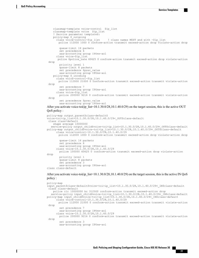
classmap-template voice-control $ip_listclassmap-template voice $ip_list! Service parameter templates:policy-map $_outgoingclass voice-control-$ip_list ! class names MUST end with -$ip_listpolice 112000 1000 0 conform-action transmit exceed-action drop violate-action drop
queue-limit 16 packetsset precedence 6aaa-accounting group IPOne-aol
class voice-$ip_listpolice $police_rate 60625 0 conform-action transmit exceed-action drop violate-action
droppriority level 1queue-limit 8 packetsset precedence $prec_valueaaa-accounting group IPOne-aol
policy-map $_incomingclass voice-control-$ip_listpolice 112000 21000 0 conform-action transmit exceed-action transmit violate-action
dropset precedence 7aaa-accounting group IPOne-aol
class voice-$ip_listpolice 200000 9216 0 conform-action transmit exceed-action transmit violate-action
dropset precedence $prec_valueaaa-accounting group IPOne-aol
After you activate voice-toi(ip_list=10.1.30.0/28,10.1.40.0/29) on the target session, this is the active OUTQoS policy :policy-map output_parent$class-default$voice-toi>ip_list=10.1.30.0/28,10.1.40.0/29<_OUT$class-defaultclass class-default
shape average 10000000service-policy output_child$voice-toi>ip_list=10.1.30.0/28,10.1.40.0/29<_OUT$class-default
policy-map output_child$voice-toi>ip_list=10.1.30.0/28,10.1.40.0/29<_OUT$class-defaultclass voice-control-10.1.30.0/28,10.1.40.0/29police 112000 1000 0 conform-action transmit exceed-action drop violate-action drop
queue-limit 16 packetsset precedence 6aaa-accounting group IPOne-aol
class voice-10.1.30.0/28,10.1.40.0/29police 100000 60625 0 conform-action transmit exceed-action drop violate-action
droppriority level 1queue-limit 8 packetsset precedence 3aaa-accounting group IPOne-aol
class class-default
After you activate voice-toi(ip_list=10.1.30.0/28,10.1.40.0/29) on the target session, this is the active IN QoSpolicy :policy-mapinput_parent$class-default$voice-toi>ip_list=10.1.30.0/28,10.1.40.0/29<_IN$class-defaultclass class-default
police cir 10000000 bc 312500 conform-action transmit exceed-action dropservice-policy input_child$voice-toi>ip_list=10.1.30.0/28,10.1.40.0/29<_IN$class-default
policy-map input_child$voice-toi>ip_list=10.1.30.0/28,10.1.40.0/29<_IN$class-defaultclass voice-control-10.1.30.0/28,10.1.40.0/29police 112000 21000 0 conform-action transmit exceed-action transmit violate-action
dropset precedence 7aaa-accounting group IPOne-aol
class voice-10.1.30.0/28,10.1.40.0/29police 200000 9216 0 conform-action transmit exceed-action transmit violate-action
dropset precedence 3aaa-accounting group IPOne-aol
QoS: Policing and Shaping Configuration Guide, Cisco IOS XE Release 3S 77
QoS Policy AccountingService Templates
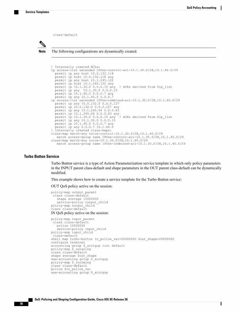
class-default
The following configurations are dynamically created.Note
! Internally created ACLs:ip access-list extended IPOne-control-acl-10.1.30.0/28,10.1.40.0/29permit ip any host 10.0.132.118permit ip host 10.0.132.118 anypermit ip any host 10.1.245.122permit ip host 10.1.245.122 anypermit ip 10.1.30.0 0.0.0.15 any ! ACEs derived from $ip_listpermit ip any 10.1.30.0 0.0.0.15permit ip 10.1.40.0 0.0.0.7 anypermit ip any 10.1.40.0 0.0.0.7
ip access-list extended IPOne-combined-acl-10.1.30.0/28,10.1.40.0/29permit ip any 10.0.132.0 0.0.0.127permit ip 10.0.132.0 0.0.0.127 anypermit ip any 10.1.245.64 0.0.0.63permit ip 10.1.245.64 0.0.0.63 anypermit ip 10.1.30.0 0.0.0.15 any ! ACEs derived from $ip_listpermit ip any 10.1.30.0 0.0.0.15permit ip 10.1.40.0 0.0.0.7 anypermit ip any 0.0.0.7 10.1.40.0
! internally created class-maps:class-map match-any voice-control-10.1.30.0/28,10.1.40.0/29
match access-group name IPOne-control-acl-10.1.30.0/28,10.1.40.0/29class-map match-any voice-10.1.30.0/28,10.1.40.0/29
match access-group name IPOne-combined-acl-10.1.30.0/28,10.1.40.0/29
Turbo Button Service
Turbo Button service is a type of Action Parameterization service template in which only policy parametersin the INPUT parent class-default and shape parameters in the OUT parent class-default can be dynamicallymodified.
This example shows how to create a service template for the Turbo Button service:
OUT QoS policy active on the session:policy-map output_parentclass class-defaultshape average 10000000service-policy output_child
policy-map output_childclass class-defaultIN QoS policy active on the session:policy-map input_parentclass class-defaultpolice 10000000service-policy input_child
policy-map input_childclass-defaultshell map turbo-button in_police_val=20000000 $out_shape=20000000configure terminalaccounting group $_acctgrp list defaultpolicy-map $_outgoingclass class-defaultshape average $out_shapeaaa-accounting group $_acctgrppolicy-map $_incomingclass class-defaultpolice $in_police_valaaa-accounting group $_acctgrp
QoS: Policing and Shaping Configuration Guide, Cisco IOS XE Release 3S78
QoS Policy AccountingService Templates
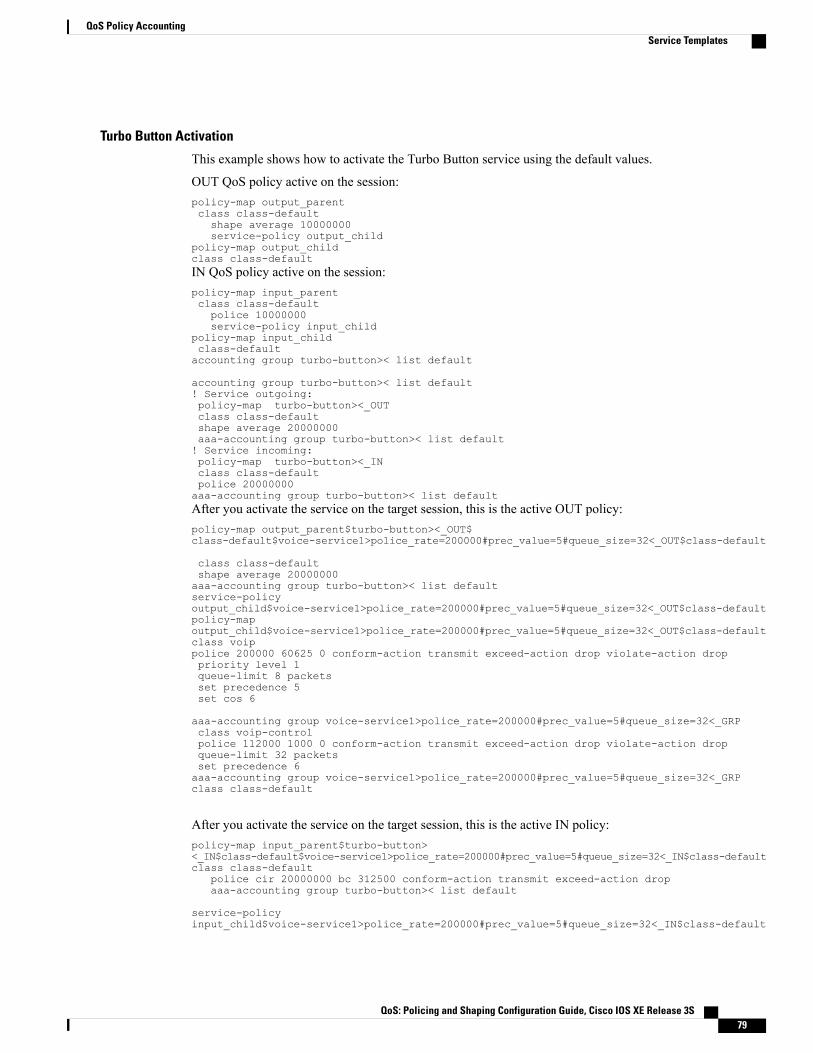
Turbo Button Activation
This example shows how to activate the Turbo Button service using the default values.
OUT QoS policy active on the session:policy-map output_parentclass class-defaultshape average 10000000service-policy output_child
policy-map output_childclass class-defaultIN QoS policy active on the session:policy-map input_parentclass class-defaultpolice 10000000service-policy input_child
policy-map input_childclass-defaultaccounting group turbo-button>< list default
accounting group turbo-button>< list default! Service outgoing:policy-map turbo-button><_OUTclass class-defaultshape average 20000000aaa-accounting group turbo-button>< list default! Service incoming:policy-map turbo-button><_INclass class-defaultpolice 20000000aaa-accounting group turbo-button>< list defaultAfter you activate the service on the target session, this is the active OUT policy:policy-map output_parent$turbo-button><_OUT$class-default$voice-service1>police_rate=200000#prec_value=5#queue_size=32<_OUT$class-default
class class-defaultshape average 20000000aaa-accounting group turbo-button>< list defaultservice-policyoutput_child$voice-service1>police_rate=200000#prec_value=5#queue_size=32<_OUT$class-defaultpolicy-mapoutput_child$voice-service1>police_rate=200000#prec_value=5#queue_size=32<_OUT$class-defaultclass voippolice 200000 60625 0 conform-action transmit exceed-action drop violate-action droppriority level 1queue-limit 8 packetsset precedence 5set cos 6
aaa-accounting group voice-service1>police_rate=200000#prec_value=5#queue_size=32<_GRPclass voip-controlpolice 112000 1000 0 conform-action transmit exceed-action drop violate-action dropqueue-limit 32 packetsset precedence 6aaa-accounting group voice-service1>police_rate=200000#prec_value=5#queue_size=32<_GRPclass class-default
After you activate the service on the target session, this is the active IN policy:policy-map input_parent$turbo-button><_IN$class-default$voice-service1>police_rate=200000#prec_value=5#queue_size=32<_IN$class-defaultclass class-default
police cir 20000000 bc 312500 conform-action transmit exceed-action dropaaa-accounting group turbo-button>< list default
service-policyinput_child$voice-service1>police_rate=200000#prec_value=5#queue_size=32<_IN$class-default
QoS: Policing and Shaping Configuration Guide, Cisco IOS XE Release 3S 79
QoS Policy AccountingService Templates
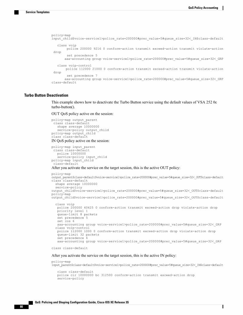
policy-mapinput_child$voice-service1>police_rate=200000#prec_value=5#queue_size=32<_IN$class-default
class voippolice 200000 9216 0 conform-action transmit exceed-action transmit violate-action
dropset precedence 5
aaa-accounting group voice-service1>police_rate=200000#prec_value=5#queue_size=32<_GRP
class voip-controlpolice 112000 21000 0 conform-action transmit exceed-action transmit violate-action
dropset precedence 7
aaa-accounting group voice-service1>police_rate=200000#prec_value=5#queue_size=32<_GRPclass-default
Turbo Button Deactivation
This example shows how to deactivate the Turbo Button service using the default values of VSA 252 0cturbo-button().
OUT QoS policy active on the session:policy-map output_parentclass class-defaultshape average 10000000service-policy output_child
policy-map output_childclass class-defaultIN QoS policy active on the session:policy-map input_parentclass class-defaultpolice 10000000service-policy input_child
policy-map input_childclass-defaultAfter you activate the service on the target session, this is the active OUT policy:policy-mapoutput_parent$class-default$voice-service1>police_rate=200000#prec_value=5#queue_size=32<_OUT$class-defaultclass class-defaultshape average 10000000service-policy
output_child$voice-service1>police_rate=200000#prec_value=5#queue_size=32<_OUT$class-defaultpolicy-mapoutput_child$voice-service1>police_rate=200000#prec_value=5#queue_size=32<_OUT$class-default
class voippolice 200000 60625 0 conform-action transmit exceed-action drop violate-action droppriority level 1queue-limit 8 packetsset precedence 5set cos 6aaa-accounting group voice-service1>police_rate=200000#prec_value=5#queue_size=32<_GRPclass voip-controlpolice 112000 1000 0 conform-action transmit exceed-action drop violate-action dropqueue-limit 32 packetsset precedence 6aaa-accounting group voice-service1>police_rate=200000#prec_value=5#queue_size=32<_GRP
class class-default
After you activate the service on the target session, this is the active IN policy:policy-mapinput_parent$class-default$voice-service1>police_rate=200000#prec_value=5#queue_size=32<_IN$class-default
class class-defaultpolice cir 10000000 bc 312500 conform-action transmit exceed-action dropservice-policy
QoS: Policing and Shaping Configuration Guide, Cisco IOS XE Release 3S80
QoS Policy AccountingService Templates
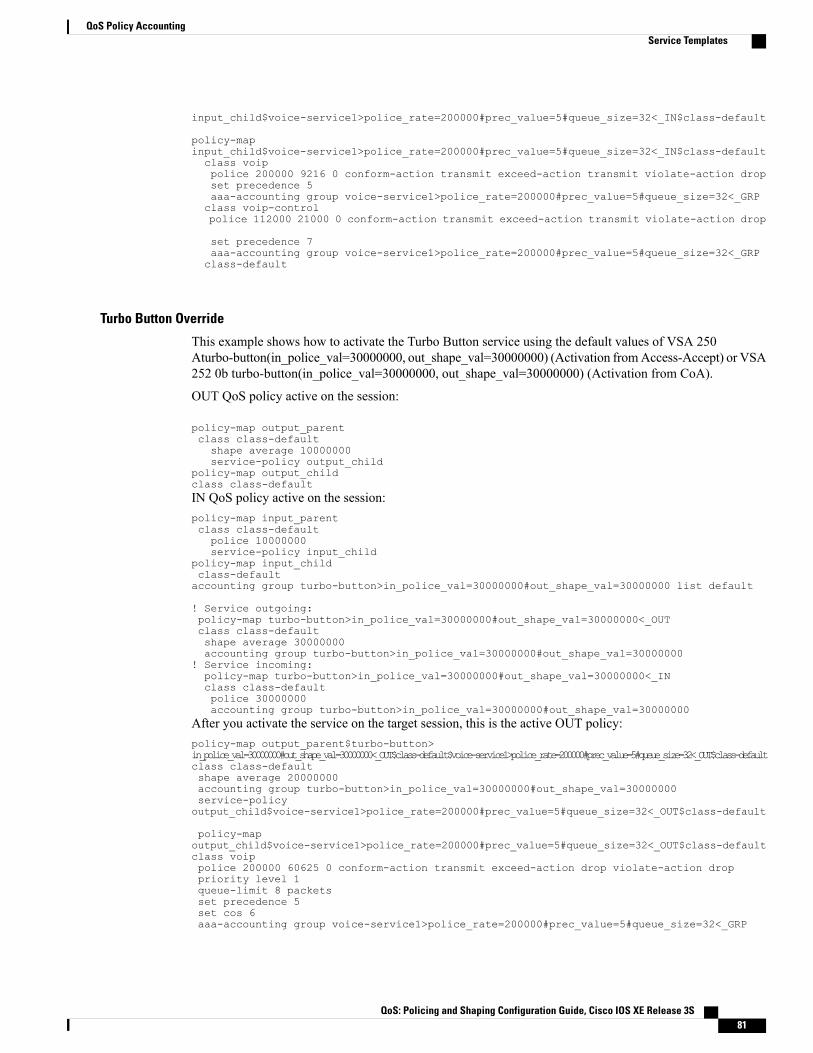
input_child$voice-service1>police_rate=200000#prec_value=5#queue_size=32<_IN$class-default
policy-mapinput_child$voice-service1>police_rate=200000#prec_value=5#queue_size=32<_IN$class-defaultclass voippolice 200000 9216 0 conform-action transmit exceed-action transmit violate-action dropset precedence 5aaa-accounting group voice-service1>police_rate=200000#prec_value=5#queue_size=32<_GRPclass voip-controlpolice 112000 21000 0 conform-action transmit exceed-action transmit violate-action drop
set precedence 7aaa-accounting group voice-service1>police_rate=200000#prec_value=5#queue_size=32<_GRPclass-default
Turbo Button Override
This example shows how to activate the Turbo Button service using the default values of VSA 250Aturbo-button(in_police_val=30000000, out_shape_val=30000000) (Activation fromAccess-Accept) or VSA252 0b turbo-button(in_police_val=30000000, out_shape_val=30000000) (Activation from CoA).
OUT QoS policy active on the session:
policy-map output_parentclass class-defaultshape average 10000000service-policy output_child
policy-map output_childclass class-defaultIN QoS policy active on the session:policy-map input_parentclass class-defaultpolice 10000000service-policy input_child
policy-map input_childclass-defaultaccounting group turbo-button>in_police_val=30000000#out_shape_val=30000000 list default
! Service outgoing:policy-map turbo-button>in_police_val=30000000#out_shape_val=30000000<_OUTclass class-defaultshape average 30000000accounting group turbo-button>in_police_val=30000000#out_shape_val=30000000
! Service incoming:policy-map turbo-button>in_police_val=30000000#out_shape_val=30000000<_INclass class-defaultpolice 30000000accounting group turbo-button>in_police_val=30000000#out_shape_val=30000000
After you activate the service on the target session, this is the active OUT policy:policy-map output_parent$turbo-button>in_police_val=30000000#out_shape_val=30000000<_OUT$class-default$voice-service1>police_rate=200000#prec_value=5#queue_size=32<_OUT$class-defaultclass class-defaultshape average 20000000accounting group turbo-button>in_police_val=30000000#out_shape_val=30000000service-policyoutput_child$voice-service1>police_rate=200000#prec_value=5#queue_size=32<_OUT$class-default
policy-mapoutput_child$voice-service1>police_rate=200000#prec_value=5#queue_size=32<_OUT$class-defaultclass voippolice 200000 60625 0 conform-action transmit exceed-action drop violate-action droppriority level 1queue-limit 8 packetsset precedence 5set cos 6aaa-accounting group voice-service1>police_rate=200000#prec_value=5#queue_size=32<_GRP
QoS: Policing and Shaping Configuration Guide, Cisco IOS XE Release 3S 81
QoS Policy AccountingService Templates
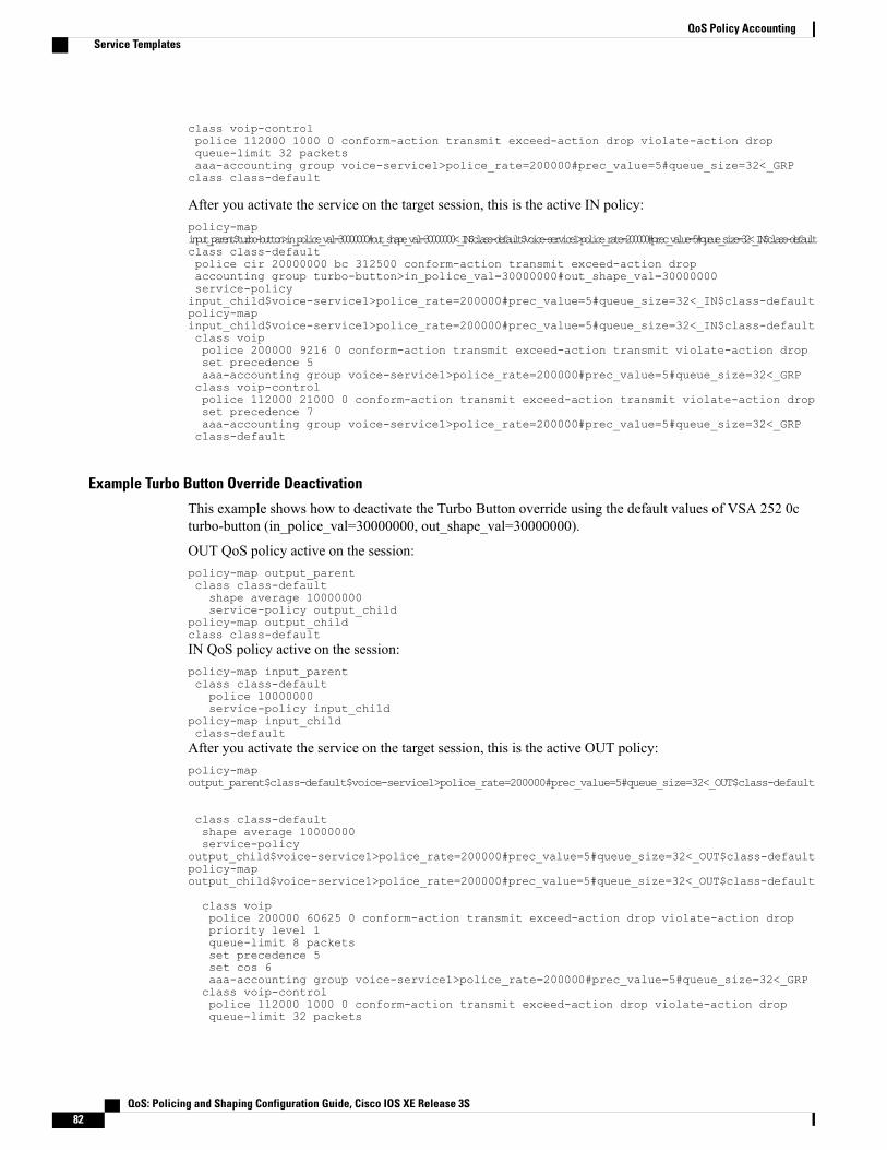
class voip-controlpolice 112000 1000 0 conform-action transmit exceed-action drop violate-action dropqueue-limit 32 packetsaaa-accounting group voice-service1>police_rate=200000#prec_value=5#queue_size=32<_GRPclass class-default
After you activate the service on the target session, this is the active IN policy:policy-mapinput_parent$turbo-button>in_police_val=30000000#out_shape_val=30000000<_IN$class-default$voice-service1>police_rate=200000#prec_value=5#queue_size=32<_IN$class-defaultclass class-defaultpolice cir 20000000 bc 312500 conform-action transmit exceed-action dropaccounting group turbo-button>in_police_val=30000000#out_shape_val=30000000service-policyinput_child$voice-service1>police_rate=200000#prec_value=5#queue_size=32<_IN$class-defaultpolicy-mapinput_child$voice-service1>police_rate=200000#prec_value=5#queue_size=32<_IN$class-defaultclass voippolice 200000 9216 0 conform-action transmit exceed-action transmit violate-action dropset precedence 5aaa-accounting group voice-service1>police_rate=200000#prec_value=5#queue_size=32<_GRPclass voip-controlpolice 112000 21000 0 conform-action transmit exceed-action transmit violate-action dropset precedence 7aaa-accounting group voice-service1>police_rate=200000#prec_value=5#queue_size=32<_GRPclass-default
Example Turbo Button Override Deactivation
This example shows how to deactivate the Turbo Button override using the default values of VSA 252 0cturbo-button (in_police_val=30000000, out_shape_val=30000000).
OUT QoS policy active on the session:policy-map output_parentclass class-defaultshape average 10000000service-policy output_child
policy-map output_childclass class-defaultIN QoS policy active on the session:policy-map input_parentclass class-defaultpolice 10000000service-policy input_child
policy-map input_childclass-defaultAfter you activate the service on the target session, this is the active OUT policy:policy-mapoutput_parent$class-default$voice-service1>police_rate=200000#prec_value=5#queue_size=32<_OUT$class-default
class class-defaultshape average 10000000service-policy
output_child$voice-service1>police_rate=200000#prec_value=5#queue_size=32<_OUT$class-defaultpolicy-mapoutput_child$voice-service1>police_rate=200000#prec_value=5#queue_size=32<_OUT$class-default
class voippolice 200000 60625 0 conform-action transmit exceed-action drop violate-action droppriority level 1queue-limit 8 packetsset precedence 5set cos 6aaa-accounting group voice-service1>police_rate=200000#prec_value=5#queue_size=32<_GRPclass voip-controlpolice 112000 1000 0 conform-action transmit exceed-action drop violate-action dropqueue-limit 32 packets
QoS: Policing and Shaping Configuration Guide, Cisco IOS XE Release 3S82
QoS Policy AccountingService Templates

set precedence 6aaa-accounting group voice-service1>police_rate=200000#prec_value=5#queue_size=32<_GRPclass class-default
After you activate the service on the target session, this is the active IN policy:policy-mapinput_parent$class-default$voice-service1>police_rate=200000#prec_value=5#queue_size=32<_IN$class-default
class class-defaultpolice cir 10000000 bc 312500 conform-action transmit exceed-action dropservice-policy
input_child$voice-service1>police_rate=200000#prec_value=5#queue_size=32<_IN$class-defaultpolicy-map
input_child$voice-service1>police_rate=200000#prec_value=5#queue_size=32<_IN$class-defaultclass voippolice 200000 9216 0 conform-action transmit exceed-action transmit violate-action dropset precedence 5aaa-accounting group voice-service1>police_rate=200000#prec_value=5#queue_size=32<_GRPclass voip-controlpolice 112000 21000 0 conform-action transmit exceed-action transmit violate-action drop
set precedence 7aaa-accounting group voice-service1>police_rate=200000#prec_value=5#queue_size=32<_GRPclass-default
Example Overriding Interim Accounting Interval
Overriding Interim Accounting Interval is a type of Action Parameterization service template in which youcan use the shell variables in place of interim interval values in the accounting method list definition, allowingthe account interim value to be dynamically modified.
This example shows how to do an accounting group override using the default values of: VSA 252 0bvoice-service1(police_rate=200000,prec_value=5,acct_interval=600).
This example generates a service with the following parameters:! Global AAA method list and accounting group parametersaaa accounting network list-600action-type start-stop periodic interval 600accounting group voice-service1>policy_rate=200000#prec_value=5#acct_interval=600 <_GRP
list list-600! OUT policy-map:policy-map voice-service1>policy_rate=200000#prec_value-5#acct_interval=600 <_OUTclass voippolice 200000 60625 0 conform-action transmit exceed-action drop violate-action droppriority level 1queue-limit 8 packetsset precedence 5set cos 6aaa-accounting group voice-service1>policy_rate=200000#prec_value=5#acct_interval=600
<_GRPclass voip-controlpolice 112000 1000 0 conform-action transmit exceed-action drop violate-action dropqueue-limit 32 packetsset precedence 6aaa-accounting group
OUT:policy-map output_parentclass class-defaultshape average 10000000service-policy output_child
policy-map output_childclass class-defaultIN:policy-map input_parentclass class-default
QoS: Policing and Shaping Configuration Guide, Cisco IOS XE Release 3S 83
QoS Policy AccountingService Templates

police 10000000service-policy input_child
policy-map input_childclass-defaultAfter you activate the service on the target session, this is the active OUT policy:policy-mapoutput_parent$class-default$voice-service1>policy_rate=200000#prev_value=5#acct_interval=600<_OUT$class-defaultclass class-defaultshape average 10000000service-policy output_child$voice-service1>policy_rate=200000#prev_value=5#acct_interval=600<_OUT$class-defaultpolicy-map output_child$voice-service1>policy_rate=200000#prev_value=5#acct_interval=600<_OUT$class-defaultclass voippolice 200000 60625 0 conform-action transmit exceed-action drop violate-action droppriority level 1queue-limit 8 packetsset precedence 5set cos 6aaa-accounting group voice-service1>policy_rate=200000#prec_value=5#acct_interval=600
<_GRPclass voip-controlpolice 112000 1000 0 conform-action transmit exceed-action drop violate-action dropqueue-limit 32 packetsset precedence 6aaa-accounting group voice-service1>policy_rate=200000#prec_value=5#acct_interval=600
<_GRPclass class-default
After you activate the service on the target session, this is the active IN policy:policy-mapinput_parent$class-default$voice-service1>policy_rate=200000#prec_value-5#acct_interval=600<_IN$class-defaultclass class-defaultpolice cir 10000000 bc 312500 conform-action transmit exceed-action dropservice-policy input_child$voice-service1>policy_rate=200000#prec_value=5#acct_interval=600<_IN$class-defaultpolicy-map input_child$voice-service1>policy_rate=200000#prec_value=5#acct_interval=600<_IN$class-defaultclass voippolice 200000 9216 0 conform-action transmit exceed-action transmit violate-action dropset precedence 5aaa-accounting group voice-service1>policy_rate=200000#prec_value=5#acct_interval=600
<_GRPclass voip-controlpolice 112000 21000 0 conform-action transmit exceed-action transmit violate-action dropset precedence 7aaa-accounting group voice-service1>policy_rate=200000#prec_value=5#acct_interval=600
<_GRPclass class-default
Subscriber Accounting AccuracyThe Subscriber Accounting Accuracy feature guarantees that the I/O packet/byte statistics in theAccounting-Stop record are accurate to within one second.
Subscriber accounting data is sent to authentication, authorization, and accounting (AAA) servers during thefollowing events:
• Configured intervals during the lifetime of the session or service
• Service logoff
• Session tear down
QoS: Policing and Shaping Configuration Guide, Cisco IOS XE Release 3S84
QoS Policy AccountingSubscriber Accounting Accuracy

Use the subscriber accounting accuracymilliseconds command to set the value for the Subscriber AccountingAccuracy feature.
Change of Authorization (CoA) ACK OrderingCoA ACK ordering sends a CoA-ACK for each CoA event before a QoS accounting record is sent for thatCoA. A CoA may contain activation or deactivation of single or multiple services.
If a service fails to install on a session the following happens:
• The entire CoA fails.
• The Policy Manager sends a CoA-NAK to the RADIUS server.
• The previous service configuration is restored
If one or more services install before a failure is detected the following happens:
• The entire CoA fails.
• Services are backed out.
• The Policy Manager sends a CoA-NAK to the RADIUS server.
• The previous service configuration is restored.
Multiservice CoAs can compose up of either of the following:
• QoS services—The Policy Manager combines the services into one net-effect policy map. Only oneQoS policy is applied to the session for all services. If the policy fails to install, the system restores thesession to use the previous policy map. In effect the session is restored to the state prior to the CoA.
• QoS and Intelligent Services Gateway (ISG) services—The Policy Manager applies the ISG servicefirst, then the QoS service. If the QoS policy fails to install, the system restores the session to the previouspolicy map. Both the ISG and QoS service are rolled back to the previous state.
For multiservice CoA only one CoA-ACK is sent when all services successfully install.
Change of Authorization RollbackThe CoA Rollback feature restores QoS policy accounting to its state before the CoAs were issued. CoARollback also properly acknowledges the RADIUS server using a CoA-NAK.
The CoA Rollback feature applies to syntax mistakes and policy install failures such as admission control andresource allocation failure.
If CoA fails, the system sends a CoA-NAK and does not send QoS accounting records. The accounting recordfor existing services keeps previous counters and continues to count new packets.
QoS Accounting High AvailabilityWhen QoS accounting is enabled in a class the policy accounting feature supports three types of events:
QoS: Policing and Shaping Configuration Guide, Cisco IOS XE Release 3S 85
QoS Policy AccountingChange of Authorization (CoA) ACK Ordering
• Start—Indicates a new accounting flow. The start record contains statistics and attributes specific to thisflow.
• Interim—Indicates how often flow statistics are reported.
• Stop—Indicates the end of an accounting flow. The stop record also contains statistics and attributesspecific to this flow.
The policy accounting feature collects the statistics for the accounting flows and sends the information to theRADIUS accounting billing server.
The QoS accounting high availability feature ensures that the start, interim, and stop accounting records arenot affected if a planned or unexpected failover occurs. When a planned or unexpected failover occurs theQoS accounting HA feature ensures that the RP switchover occurs without interrupting the flow of informationto the RADIUS accounting billing server. The feature also ensures that all QoS services on all active sessionscontinue without any interruption and that the service accounting counters persist across the RP switchover.
Persistence of Policy Accounting States
To ensure that start, stop, and interim accounting is not affected by a stateful switchover (SSO) or an in-servicesoftware upgrade (ISSU), the Policy Manager synchronizes all QoS services and parameterized CoAfunctionality with the standby RP at the time of the failover. In addition, the dynamic QoS configurations andthe polling interval are synchronized between the active and standby RPs.
To synchronize a parameterized CoA event to a standby RP, the Policy Manager performs the followingfunctions:
• Manages the CoA replay to synchronize provisioning events on the standby RP.
• Uses the same service template on both the active and standby RP.
• Creates the same policy map and class map names to apply to the session on both the active ad standbyRP.
• Uses predefined QoS policy maps and class maps during service template activation.
Persistence of Policy Accounting Counters
The QoSAccounting HA feature ensures that the policy accounting counters persist across an SSO or failover.After a switchover occurs, the standby RP becomes the active RP and accumulates the statistics from thepreviously active RP. If the newly active RP receives a periodic update after the switchover it generates aninterim record using the statistics it accumulated plus the values from the periodic update. If the newly activeRP does not receive a periodic update after the switchover, it generates the interim record using only thestatistics it accumulated from the previously active RP.
For more information on SSOs and ISSUs, see the Cisco IOS High Availability Configuration Guide.
How to Use QoS Policy AccountingTo use QoS Policy Accounting you must assign a group or AAA method list to a traffic class, then youconfigure the service template for policy accounting, and finally you activate the subscriber accountingaccuracy functionality.
QoS: Policing and Shaping Configuration Guide, Cisco IOS XE Release 3S86
QoS Policy AccountingHow to Use QoS Policy Accounting

By default, QoS Policy Accounting is not assigned to traffic classes.Note
Assigning a Group or AAA Method List to a Traffic Class
Before You Begin
Ensure the group or AAA method list already exists. If you try to add an undefined group or AAA methodlist to a traffic class, you will receive an error message.
SUMMARY STEPS
1. enable2. configure terminal3. aaa authentication ppp list-name method14. aaa accounting network methodlist-name5. action-type start-stop6. periodic interval minutes7. accounting group group_name list list-name8. policy-map policy-map-name9. class class-default10. accounting aaa list list-name [group-name]11. end12. show policy-map session13. show accounting group group-name
DETAILED STEPS
PurposeCommand or Action
Enables privileged EXEC mode.enableStep 1
Example:
Router> enable
• Enter your password if prompted.
Enters global configuration mode.configure terminal
Example:
Router# configure terminal
Step 2
Specifies a valid AAA authentication method.aaa authentication ppp list-name method1Step 3
QoS: Policing and Shaping Configuration Guide, Cisco IOS XE Release 3S 87
QoS Policy AccountingAssigning a Group or AAA Method List to a Traffic Class

PurposeCommand or Action
Example:
Router(config)# aaa authentication pppgroup radius
• Group RADIUS enables global RADIUS authentication.
Enables AAA of services when you use RADIUS.aaa accounting network methodlist-nameStep 4
Example:Router(config)# aaa accounting networklist1
• The algorithm determining the interim interval for a class orgroup uses the method list specified here.
Sends a start accounting notice at the beginning of a process anda stop accounting notice at the end of a process.
action-type start-stop
Example:
Router(config)# action-type start-stop
Step 5
Adds the interim interval value (1 to 71,582minutes) in the methodlist, if specified.
periodic interval minutes
Example:
Router(config)# periodic interval 1
Step 6
• If you do not define an interim interval, the global valuedefined by AAA is used.
• If the method list disables interim updates, the accountingflows using the method list do not generate an interim update.
Sets properties in the AAA method list.accounting group group_name list list-nameStep 7
Example:
Router(config)# accounting groupgroup_name AAAmethodlist AAAmethodlist1
• You can make per-session changes to existing traffic classesby temporarily overwriting properties in the groups or AAAmethod lists to which they are assigned. This allows you toprovide dynamic customized QoS configuration to eachsubscriber.
Creates a policy map.policy-map policy-map-name
Example:
Router(config)# policy-map p1
Step 8
Creates a traffic class.class class-default
Example:
Router(config)# class class-default
Step 9
Assigns the traffic class to a group or an AAA method list.accounting aaa list list-name [group-name]Step 10
QoS: Policing and Shaping Configuration Guide, Cisco IOS XE Release 3S88
QoS Policy AccountingAssigning a Group or AAA Method List to a Traffic Class

PurposeCommand or Action
Example:
Router(config)# accounting aaa listAAAmethodlist1
• This example shows the QoS Policy Accounting featureenabled for instances of a traffic class using listAAAmethodlist1 with no group.
Exits interface configurationmode and returns to privileged EXECmode.
end
Example:
Router(config)# end
Step 11
(Optional) Displays QoS Policy Accounting feature informationfor traffic classes with a group or an AAA method list.
show policy-map session
Example:
Router# show policy-map session
Step 12
(Optional) Displays all group-to-method list associations.show accounting group group-nameStep 13
Example:
Router# show accounting group acc-group1
• Enter a group name to view information specific to thatgroup.
Activating Subscriber Accounting Accuracy
SUMMARY STEPS
1. enable2. configure terminal3. subscriber accounting accuracy milliseconds4. end
DETAILED STEPS
PurposeCommand or Action
Enables privileged EXEC mode.enableStep 1
Example:
Device> enable
• Enter your password if prompted.
QoS: Policing and Shaping Configuration Guide, Cisco IOS XE Release 3S 89
QoS Policy AccountingActivating Subscriber Accounting Accuracy

PurposeCommand or Action
Enters global configuration mode.configure terminal
Example:
Device# configure terminal
Step 2
Sets the value for the Subscriber Accounting Accuracyfeature.
subscriber accounting accuracy milliseconds
Example:
Device(config)# subscriber accounting accuracy1000
Step 3
Enters privileged EXEC mode.end
Example:
Device(config)# end
Step 4
Troubleshooting Service TemplatesTo troubleshoot any service template issues, you can display usage information for all template service policymaps on your router.
SUMMARY STEPS
1. enable2. show subscriber policy ppm-shim-db
DETAILED STEPS
PurposeCommand or Action
Enables privileged EXEC mode.enableStep 1
Example:
Router> enable
• Enter your password if prompted.
Displays reference counts (usage) of all template servicepolicy-maps and Net Effect policy-maps on the router.
show subscriber policy ppm-shim-db
Example:
Router(config)# show subscriber policyppm-shim-db
Step 2
QoS: Policing and Shaping Configuration Guide, Cisco IOS XE Release 3S90
QoS Policy AccountingTroubleshooting Service Templates
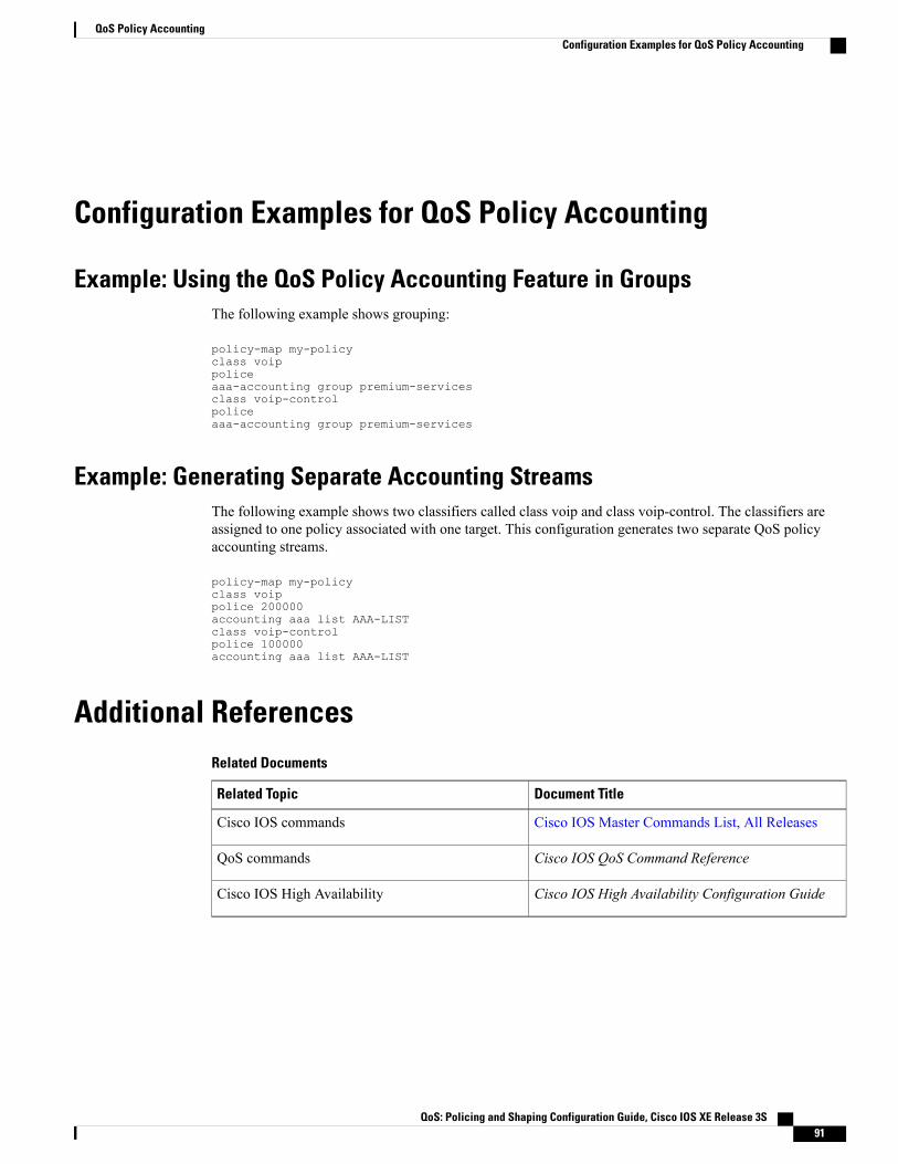
Configuration Examples for QoS Policy Accounting
Example: Using the QoS Policy Accounting Feature in GroupsThe following example shows grouping:
policy-map my-policyclass voippoliceaaa-accounting group premium-servicesclass voip-controlpoliceaaa-accounting group premium-services
Example: Generating Separate Accounting StreamsThe following example shows two classifiers called class voip and class voip-control. The classifiers areassigned to one policy associated with one target. This configuration generates two separate QoS policyaccounting streams.
policy-map my-policyclass voippolice 200000accounting aaa list AAA-LISTclass voip-controlpolice 100000accounting aaa list AAA-LIST
Additional ReferencesRelated Documents
Document TitleRelated Topic
Cisco IOS Master Commands List, All ReleasesCisco IOS commands
Cisco IOS QoS Command ReferenceQoS commands
Cisco IOS High Availability Configuration GuideCisco IOS High Availability
QoS: Policing and Shaping Configuration Guide, Cisco IOS XE Release 3S 91
QoS Policy AccountingConfiguration Examples for QoS Policy Accounting

Standards
TitleStandard
--No new or modified standards are supported by thisfeature, and support for existing standards has notbeen modified by this feature.
MIBs
MIBs LinkMIB
To locate and downloadMIBs for selected platforms,Cisco software releases, and feature sets, use CiscoMIB Locator found at the following URL:
http://www.cisco.com/go/mibs
No new or modified MIBs are supported by thisfeature, and support for existing MIBs has not beenmodified by this feature.
RFCs
TitleRFC
RADIUS AccountingRFC 2866
Technical Assistance
LinkDescription
http://www.cisco.com/cisco/web/support/index.htmlThe Cisco Support and Documentation websiteprovides online resources to download documentation,software, and tools. Use these resources to install andconfigure the software and to troubleshoot and resolvetechnical issues with Cisco products and technologies.Access to most tools on the Cisco Support andDocumentation website requires a Cisco.com user IDand password.
Feature Information for the QoS Policy Accounting FeatureThe following table provides release information about the feature or features described in this module. Thistable lists only the software release that introduced support for a given feature in a given software releasetrain. Unless noted otherwise, subsequent releases of that software release train also support that feature.
Use Cisco Feature Navigator to find information about platform support and Cisco software image support.To access Cisco Feature Navigator, go to www.cisco.com/go/cfn. An account on Cisco.com is not required.
QoS: Policing and Shaping Configuration Guide, Cisco IOS XE Release 3S92
QoS Policy AccountingFeature Information for the QoS Policy Accounting Feature
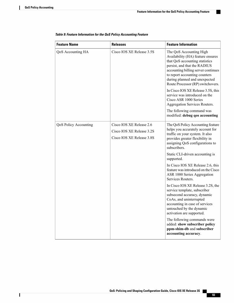
Table 9: Feature Information for the QoS Policy Accounting Feature
Feature InformationReleasesFeature Name
The QoS Accounting HighAvailability (HA) feature ensuresthat QoS accounting statisticspersist, and that the RADIUSaccounting billing server continuesto report accounting countersduring planned and unexpectedRoute Processor (RP) switchovers.
In Cisco IOSXERelease 3.5S, thisservice was introduced on theCisco ASR 1000 SeriesAggregation Services Routers.
The following command wasmodified: debug qos accounting
Cisco IOS XE Release 3.5SQoS Accounting HA
TheQoS PolicyAccounting featurehelps you accurately account fortraffic on your system. It alsoprovides greater flexibility inassigning QoS configurations tosubscribers.
Static CLI-driven accounting issupported.
In Cisco IOS XE Release 2.6, thisfeature was introduced on the CiscoASR 1000 Series AggregationServices Routers.
In Cisco IOS XE Release 3.2S, theservice template, subscribersubsecond accuracy, dynamicCoAs, and uninterruptedaccounting in case of servicesuntouched by the dynamicactivation are supported.
The following commands wereadded: show subscriber policyppm-shim-db and subscriberaccounting accuracy.
Cisco IOS XE Release 2.6
Cisco IOS XE Release 3.2S
Cisco IOS XE Release 3.8S
QoS Policy Accounting
QoS: Policing and Shaping Configuration Guide, Cisco IOS XE Release 3S 93
QoS Policy AccountingFeature Information for the QoS Policy Accounting Feature

QoS: Policing and Shaping Configuration Guide, Cisco IOS XE Release 3S94
QoS Policy AccountingFeature Information for the QoS Policy Accounting Feature

C H A P T E R 8PPP Session Queueing on ATM VCs
The PPP Session Queueing on ATM VCs feature enables you to shape and queue PPP over Ethernet overATM (PPPoEoA) sessions to a user-specified rate. Multiple sessions can exist on any ATM VC and haveQuality of Service (QoS) policies applied, or some of the sessions might have QoS policies. The routershapes the sum of allbandwidth used for PPPoEoA traffic on a VC so that the subscriber’s connection to theDigital Subscriber Line Access Multiplexer (DSLAM) does not become congested. Queueing-relatedfunctionality provides different levels of service to the various applications that run over the PPPoEoAsession.
A nested, two-level hierarchical service policy is used to configure session shaping directly on the routerusing the modular quality of service command-line interface (MQC). The hierarchical policy consists of thefollowing:
• Child policy--Defines QoS actions using QoS commands such as the priority, bandwidth, and policecommands.
• Parent policy--Contains only the class-default class with the shape or bandwidth remaining ratiocommand configured, or with both commands configured:
• shape command--Shapes the session traffic to the specified bit rate, according to a specificalgorithm.
• bandwidth remaining ratio command--Specifies a ratio value that the router uses to determinehow much unused bandwidth to allocate to the session during congestion.
The PPP Session Queueing on ATMVCs feature works with both PPP terminated aggregation (PTA) andL2TP access concentrator (LAC) configurations.
Note
The figure below illustrates PPP session Queueing on ATM VCs.
QoS: Policing and Shaping Configuration Guide, Cisco IOS XE Release 3S 95

• Finding Feature Information, page 96
• Prerequisites for PPP Session Queueing on ATM VCs, page 96
• Restrictions for PPP Session Queueing on ATM VCs, page 97
• Information About PPP Session Queueing on ATM VCs, page 97
• How to Configure PPP Session Queueing on ATM VCs, page 99
• Configuration Examples for PPP Session Queueing on ATM VCs, page 109
• Additional References, page 112
• Feature Information for PPP Session Queueing on ATM VCs, page 112
Finding Feature InformationYour software release may not support all the features documented in this module. For the latest caveats andfeature information, see Bug Search Tool and the release notes for your platform and software release. Tofind information about the features documented in this module, and to see a list of the releases in which eachfeature is supported, see the feature information table at the end of this module.
Use Cisco Feature Navigator to find information about platform support and Cisco software image support.To access Cisco Feature Navigator, go to www.cisco.com/go/cfn. An account on Cisco.com is not required.
Prerequisites for PPP Session Queueing on ATM VCs• PPPoEoA sessions must be enabled.
• Create traffic classes using the class-map command and specify the match criteria used to classify traffic.
• For dynamic PPPoEoA session queueing using RADIUS, you must:
• Enable authentication, authorization, and accounting (AAA) on the router
QoS: Policing and Shaping Configuration Guide, Cisco IOS XE Release 3S96
PPP Session Queueing on ATM VCsFinding Feature Information

• Configure the RADIUS server for dynamic QoS
• Create the subscriber’s user profile on the RADIUS server
Restrictions for PPP Session Queueing on ATM VCs• You cannot configure PPP session queueing on unshaped VCs--VCs without a specified peak cell rate(PCR) or sustained cell rate (SCR).
• VCs with session queueing polices cannot be part of a shaped virtual path (VP).
• If the same ATM category (for example, shaped unspecified bit rate (UBR)) contains both high and lowbandwidth VCs, the SARmechanism can cause low throughput for high bandwidth VCs. Theworkaroundis to use different ATM classes for low and high bandwidth VCs. For example, configure low bandwidthVCs as shaped UBR and high bandwidth VCs as variable bit rate-nonreal-time (VBR-nrt) or constantbit rate (CBR).
• The CLASS-BASED QOS MIB does not include statistics for service policies applied to sessions.
• RADIUS accounting does not include queueing statistics.
Information About PPP Session Queueing on ATM VCs
Dynamically Applying QoS Policies to PPP Sessions on ATM VCsThe router allows you to dynamically apply QoS policy maps to PPPoEoA sessions using RADIUS. Althoughthe actual configuration of the QoS policies occurs on the router, you can configure the following attribute-value(AV) pairs on RADIUS to specify the name of the policy map to dynamically apply to the session:
"ip:sub-qos-policy-in=<name of the QoS policy in ingress direction>""ip:sub-qos-policy-out=<name of egress policy>"You define the AV pairs in one of the following RADIUS profiles:
• User profile--The user profile on the RADIUS server contains an entry that identifies the policy mapname applicable to the user. The policy map name is the service that RADIUS downloads to the routerafter a session is authorized.
• Service profile--The service profile on the RADIUS server specifies a session identifier and an AV pair.The session identifier might be, for example, the IP address of the session. The AV pair defines theservice (policy map name) to which the user belongs.
After receiving a service-logon request from the policy server, RADIUS sends a change of authorization(CoA) request to the router to activate the service for the subscriber, who is already logged in. If theauthorization succeeds, the router downloads the name of the policy map from RADIUS using theip:sub-qos-policy-in[out]= AV-pair and applies the QoS policy to the PPPoEoA session. Because the servicepolicy contains queueing-related actions, the router sets up the appropriate class queues.
QoS: Policing and Shaping Configuration Guide, Cisco IOS XE Release 3S 97
PPP Session Queueing on ATM VCsRestrictions for PPP Session Queueing on ATM VCs

Although the router also supports the RADIUS vendor specific attribute (VSA) 38, Cisco-Policy-Downand Cisco-Policy-Up, we recommend that you use the ip:sub-qos-policy-in[out]= AV pairs for QoS policydefinitions.
Note
PPP Session Queueing InheritancePPP Sessions either inherit queues from their parent interface or they have their own queues. Each PPPoEoAsession for which session queueing is configured has its own set of queues.
The table below describes the queues to which the router directs session traffic.
Table 10: PPP Session Queue Inheritance
Queue Used for Session TrafficQueueing Policy
VC default queueNo policy
VC queuesApplied to the VC
Session queuesApplied to the session
Interfaces Supporting PPP Session QueueingThe router supports PPP session queueing on shaped ATM VCs for outbound traffic only.
The router does not support PPP session queueing on inbound ATM interfaces.
Mixed Configurations and QueueingA mixed configuration is one in which all sessions do not have QoS applied to them. On some VCs, thequeueing policy is applied at the VC level, and on other VCs the queueing policies are applied on the sessions.Some sessions have no policy applied at all. As a result, the router uses the hierarchical queueing framework(HQF) to direct traffic in the following ways:
• If no queueing policy is applied at the VC or session level, the router sends all traffic on the VC to thedefault queue, including traffic from sessions on the VC that have a policing-only policy applied or nopolicy applied.
• If a queueing policy is applied at the VC level, but not at the session level, the router sends traffic to thequeues associated with the queueing policy on the VC.
• If queueing policies are applied to some sessions on a VC but not to other sessions, the router sends thetraffic with a policing-only policy or with no policy applied to the VC’s default queue. The router sendstraffic with queueing policies to the queues associated with the queueing policy applied to the session.
QoS: Policing and Shaping Configuration Guide, Cisco IOS XE Release 3S98
PPP Session Queueing on ATM VCsPPP Session Queueing Inheritance
Bandwidth Mode and ATM Port OversubscriptionAn ATM port can operate in reserved bandwidth mode or shared bandwidth mode.
When a port is not oversubscribed (the sum of the bandwidths of all VCs on the port is less than the portbandwidth), the port operates in reserved bandwidth mode--a specific amount of bandwidth is reserved foreach VC on the port. If a VC does not use all of its allocated bandwidth, the unused bandwidth is not sharedamong the VCs on the port.
When the ATM port is oversubscribed (the sum of the bandwidths of all VCs on the port is greater than theport bandwidth), the port operates in shared bandwidth mode. In this mode, any unused bandwidth is availablefor reuse by the other VCs on the port, up to the VC’s respective shape rate--traffic on a VC cannot exceedthe shape rate of that VC.
Oversubscription at the Session LevelOversubscription at the session level occurs after session traffic shaping and when the aggregate session trafficexceeds the subinterface shape rate. After all priority traffic is accounted for, the router distributes the remainingbandwidth on the VC to the sessions according to the value specified in the bandwidth remaining ratio commandconfigured in the parent policy of the policy applied to the sessions. If the bandwidth remaining ratio commandis not specified in the parent policy, the router uses a default ratio of 1.
How to Configure PPP Session Queueing on ATM VCs
Configuring PPP Session Queueing Using a Virtual TemplateA virtual templat e is a logical interface whose configuration can specify generic configuration informationfor a specific purpose, user-specific configuration information, and router-dependent information. Youconfigure a virtual template on an interface and apply QoS policy maps to the virtual template. The virtualtemplate inherits the QoS features specified in the policy map. When the router establishes sessions on aninterface, the router applies the QoS features specified in the virtual template configuration to the virtualaccess interfaces (VAIs) created for the sessions, including the QoS features specified in the policy mapattached to the virtual template.
A broadband aggregation group (bba-group) configured on an ATM interface points to the virtual templatethe router uses to apply QoS policies to sessions. When a session arrives on an ATM interface, the routercreates a virtual access interface (VAI) for the session and applies the policies associated with the virtualtemplate to the sessions.
To configure PPPoEoA session queueing using a virtual template, perform the following configuration tasks:
QoS: Policing and Shaping Configuration Guide, Cisco IOS XE Release 3S 99
PPP Session Queueing on ATM VCsBandwidth Mode and ATM Port Oversubscription

Configuring an Hierarchical QoS Policy
SUMMARY STEPS
1. enable2. configure terminal3. policy-map policy-map-name4. class class-map-name5. priority level level6. police bps [burst-normal burst-max] [conform-action action] [exceed-action action] violate-action
action7. set cos value8. bandwidth remaining ratio9. exit10. policy-map policy-map-name11. class class-default12. bandwidth remaining ratio13. shape [average] mean-rate[burst-size] [excess-burst-size]14. service-policy policy-map-name
DETAILED STEPS
PurposeCommand or Action
Enables privileged EXEC mode.enableStep 1
Example:
Router> enable
• Enter your password if prompted.
Enters global configuration mode.configure terminal
Example:
Router# configure terminal
Step 2
Creates or modifies the child policy. Enters policy-map configuration mode.policy-map policy-map-nameStep 3
Example:
Router(config)# policy-mappolicy-map-name
policy-map-name is the name of the child policy map.
QoS: Policing and Shaping Configuration Guide, Cisco IOS XE Release 3S100
PPP Session Queueing on ATM VCsConfiguring PPP Session Queueing Using a Virtual Template
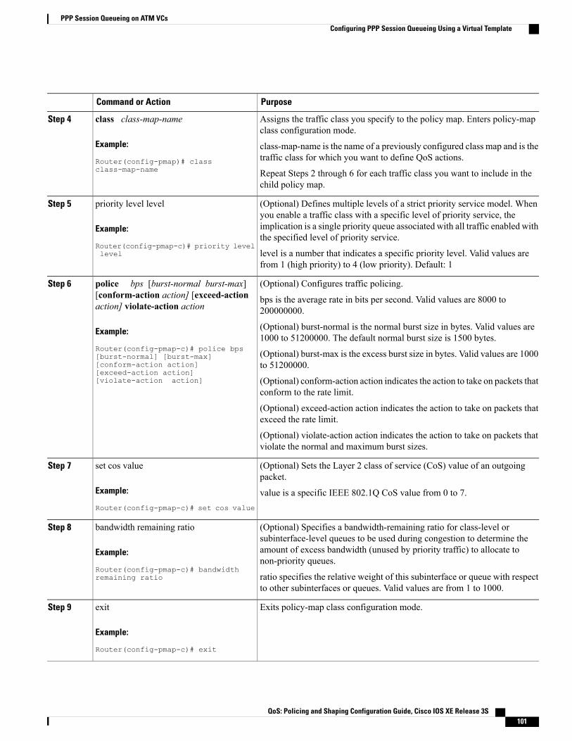
PurposeCommand or Action
Assigns the traffic class you specify to the policy map. Enters policy-mapclass configuration mode.
class class-map-name
Example:
Router(config-pmap)# classclass-map-name
Step 4
class-map-name is the name of a previously configured class map and is thetraffic class for which you want to define QoS actions.
Repeat Steps 2 through 6 for each traffic class you want to include in thechild policy map.
(Optional) Defines multiple levels of a strict priority service model. Whenyou enable a traffic class with a specific level of priority service, the
priority level level
Example:
Router(config-pmap-c)# priority levellevel
Step 5
implication is a single priority queue associated with all traffic enabled withthe specified level of priority service.
level is a number that indicates a specific priority level. Valid values arefrom 1 (high priority) to 4 (low priority). Default: 1
(Optional) Configures traffic policing.police bps [burst-normal burst-max][conform-action action] [exceed-actionaction] violate-action action
Step 6
bps is the average rate in bits per second. Valid values are 8000 to200000000.
Example:
Router(config-pmap-c)# police bps
(Optional) burst-normal is the normal burst size in bytes. Valid values are1000 to 51200000. The default normal burst size is 1500 bytes.
(Optional) burst-max is the excess burst size in bytes. Valid values are 1000to 51200000.
[burst-normal] [burst-max][conform-action action][exceed-action action][violate-action action] (Optional) conform-action action indicates the action to take on packets that
conform to the rate limit.
(Optional) exceed-action action indicates the action to take on packets thatexceed the rate limit.
(Optional) violate-action action indicates the action to take on packets thatviolate the normal and maximum burst sizes.
(Optional) Sets the Layer 2 class of service (CoS) value of an outgoingpacket.
set cos value
Example:
Router(config-pmap-c)# set cos value
Step 7
value is a specific IEEE 802.1Q CoS value from 0 to 7.
(Optional) Specifies a bandwidth-remaining ratio for class-level orsubinterface-level queues to be used during congestion to determine the
bandwidth remaining ratio
Example:
Router(config-pmap-c)# bandwidthremaining ratio
Step 8
amount of excess bandwidth (unused by priority traffic) to allocate tonon-priority queues.
ratio specifies the relative weight of this subinterface or queue with respectto other subinterfaces or queues. Valid values are from 1 to 1000.
Exits policy-map class configuration mode.exit
Example:
Router(config-pmap-c)# exit
Step 9
QoS: Policing and Shaping Configuration Guide, Cisco IOS XE Release 3S 101
PPP Session Queueing on ATM VCsConfiguring PPP Session Queueing Using a Virtual Template
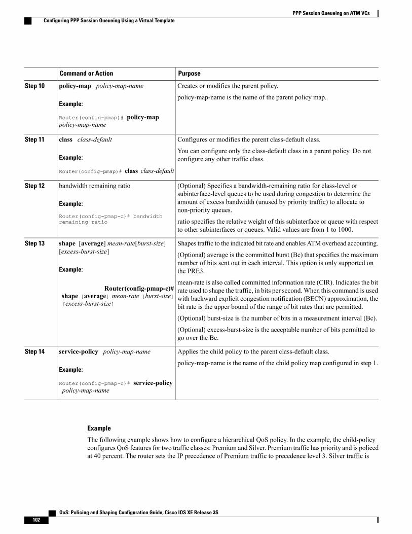
PurposeCommand or Action
Creates or modifies the parent policy.policy-map policy-map-nameStep 10
Example:
Router(config-pmap)# policy-mappolicy-map-name
policy-map-name is the name of the parent policy map.
Configures or modifies the parent class-default class.class class-defaultStep 11
Example:
Router(config-pmap)# class class-default
You can configure only the class-default class in a parent policy. Do notconfigure any other traffic class.
(Optional) Specifies a bandwidth-remaining ratio for class-level orsubinterface-level queues to be used during congestion to determine the
bandwidth remaining ratio
Example:
Router(config-pmap-c)# bandwidthremaining ratio
Step 12
amount of excess bandwidth (unused by priority traffic) to allocate tonon-priority queues.
ratio specifies the relative weight of this subinterface or queue with respectto other subinterfaces or queues. Valid values are from 1 to 1000.
Shapes traffic to the indicated bit rate and enables ATMoverhead accounting.shape [average] mean-rate[burst-size][excess-burst-size]
Step 13
(Optional) average is the committed burst (Bc) that specifies the maximumnumber of bits sent out in each interval. This option is only supported onthe PRE3.Example:
mean-rate is also called committed information rate (CIR). Indicates the bitrate used to shape the traffic, in bits per second.When this command is usedRouter(config-pmap-c)#
shape [average] mean-rate [burst-size][excess-burst-size]
with backward explicit congestion notification (BECN) approximation, thebit rate is the upper bound of the range of bit rates that are permitted.
(Optional) burst-size is the number of bits in a measurement interval (Bc).
(Optional) excess-burst-size is the acceptable number of bits permitted togo over the Be.
Applies the child policy to the parent class-default class.service-policy policy-map-nameStep 14
Example:
Router(config-pmap-c)# service-policypolicy-map-name
policy-map-name is the name of the child policy map configured in step 1.
Example
The following example shows how to configure a hierarchical QoS policy. In the example, the child-policyconfigures QoS features for two traffic classes: Premium and Silver. Premium traffic has priority and is policedat 40 percent. The router sets the IP precedence of Premium traffic to precedence level 3. Silver traffic is
QoS: Policing and Shaping Configuration Guide, Cisco IOS XE Release 3S102
PPP Session Queueing on ATM VCsConfiguring PPP Session Queueing Using a Virtual Template
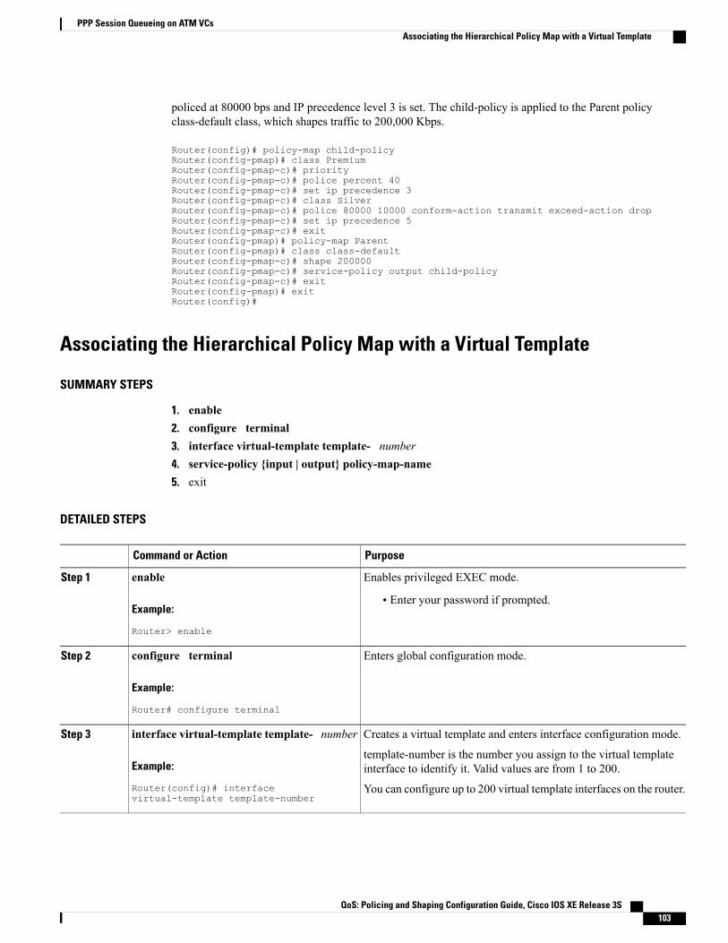
policed at 80000 bps and IP precedence level 3 is set. The child-policy is applied to the Parent policyclass-default class, which shapes traffic to 200,000 Kbps.
Router(config)# policy-map child-policyRouter(config-pmap)# class PremiumRouter(config-pmap-c)# priorityRouter(config-pmap-c)# police percent 40Router(config-pmap-c)# set ip precedence 3Router(config-pmap-c)# class SilverRouter(config-pmap-c)# police 80000 10000 conform-action transmit exceed-action dropRouter(config-pmap-c)# set ip precedence 5Router(config-pmap-c)# exitRouter(config-pmap)# policy-map ParentRouter(config-pmap)# class class-defaultRouter(config-pmap-c)# shape 200000Router(config-pmap-c)# service-policy output child-policyRouter(config-pmap-c)# exitRouter(config-pmap)# exitRouter(config)#
Associating the Hierarchical Policy Map with a Virtual Template
SUMMARY STEPS
1. enable2. configure terminal3. interface virtual-template template- number4. service-policy {input | output} policy-map-name5. exit
DETAILED STEPS
PurposeCommand or Action
Enables privileged EXEC mode.enableStep 1
Example:
Router> enable
• Enter your password if prompted.
Enters global configuration mode.configure terminal
Example:
Router# configure terminal
Step 2
Creates a virtual template and enters interface configuration mode.interface virtual-template template- numberStep 3
Example:
Router(config)# interfacevirtual-template template-number
template-number is the number you assign to the virtual templateinterface to identify it. Valid values are from 1 to 200.
You can configure up to 200 virtual template interfaces on the router.
QoS: Policing and Shaping Configuration Guide, Cisco IOS XE Release 3S 103
PPP Session Queueing on ATM VCsAssociating the Hierarchical Policy Map with a Virtual Template

PurposeCommand or Action
Attaches the policy map you specify to the virtual template interfacein the inbound or outbound direction that you specify.
service-policy {input | output}policy-map-name
Step 4
Example:
Router(config-if)# service-policy {input| output} policy-map-name
input specifies to apply the policy map to inbound traffic.
output specifies to apply the policy map to outbound traffic.
policy-map-name is the name of a previously configured policy map.
Exits interface configuration mode.exit
Example:
Router(config-if)# exit
Step 5
Example
The following example shows how to associate a policy map with a virtual template. In this example, thepolicy map named Parent is associated with the virtual template named VirtualTemplate1.
Router(config)# interface virtual-template1Router(config-if)# service-policy output ParentRouter(config-if)# exitRouter(config)#
Applying the Virtual Template to an ATM Subinterface
SUMMARY STEPS
1. enable2. configure terminal3. bba-group pppoe group-name4. virtual-template template-number5. exit6. interface atm number.subinterface [point-to-point]7. pvc [name] vpi/vci8. protocol pppoe group group-name9. exit10. exit
QoS: Policing and Shaping Configuration Guide, Cisco IOS XE Release 3S104
PPP Session Queueing on ATM VCsApplying the Virtual Template to an ATM Subinterface

DETAILED STEPS
PurposeCommand or Action
Enables privileged EXEC mode.enableStep 1
Example:
Router> enable
• Enter your password if prompted.
Enters global configuration mode.configure terminal
Example:
Router# configure terminal
Step 2
Creates a PPP over Ethernet (PPPoE) profile. Enters BBA group configurationmode.
bba-group pppoe group-name
Example:
Router(config)# bba-group pppoegroup-name
Step 3
group-name is the name of the PPPoE profile.
Associates a BBA group to the virtual template to be used for cloning virtualaccess interfaces.
virtual-template template-number
Example:
Router(config-bba-grp)#virtual-template template-number
Step 4
template-number is the identifying number of the virtual template.
Exits BBA group configuration mode.exit
Example:
Router(config-bba-grp)# exit
Step 5
Creates or modifies a subinterface. Enters subinterface configuration mode.interface atm number.subinterface[point-to-point]
Step 6
atm is the interface type.
Example:
Router(config)# interface atm
number is the slot, module, and port number of the interface (for example1/0/0).
.subinterface is the number of the subinterface (for example, 1/0/0.1).number.subinterface[point-to-point]
(Optional) point-to-point indicates that the subinterface connects directly withanother subinterface.
Creates or modifies an ATM permanent virtual circuit (PVC). Enters ATMvirtual circuit configuration mode.
pvc [name] vpi/vci
Example:
Router(config-subif) pvc [name]vpi/vci
Step 7
(Optional) name identifies the PVC and can contain up to 15 characters.
vpi/ specifies the ATM network virtual path identifier (VPI) for this PVC.You must specify the slash. Valid values are from 0 to 255. The router treatsa value that is outside the range of valid values as the connection ID. Thedefault value is 0.
QoS: Policing and Shaping Configuration Guide, Cisco IOS XE Release 3S 105
PPP Session Queueing on ATM VCsApplying the Virtual Template to an ATM Subinterface
PurposeCommand or Action
The arguments vpi and vci cannot both be set to 0; if one is 0, theother cannot be 0.
Note
vci specifies the ATM network virtual channel identifier (VCI) for this PVC.Valid values are from 0 to 1 less than the maximum value set for this interfaceby the atm vc-per-vp command. A value that is out of range causes an "unrecognized command" error message.
The VCI value has local significance only and, therefore, is unique only on asingle link, not throughout the ATM network. Typically, lower values from0 to 31 are reserved for specific traffic (for example, F4 OAM, SVC signaling,ILMI, and so on) and should not be used.
Enables PPP over Ethernet (PPPoE) sessions to be established on permanentvirtual circuits (PVCs).
protocol pppoe group group-name
Example:
Router(config-atm-vc)# protocolpppoe group group-name
Step 8
group specifies a PPPoE profile (bba-group) to be used by PPPoE sessionson the interface.
group-name is the name of the PPPoE profile (bba-group) to be used by PPPoEsessions on the interface.
The group group-name points to the bba-group to be used for applying a virtualtemplate interface with QoS policies to sessions.
Exits ATM virtual circuit configuration mode.exit
Example:
Router(config-atm-vc)# exit
Step 9
Exits subinterface configuration mode.exit
Example:
Router(config-subif)# exit
Step 10
Examples
The following example shows how to associate a virtual template interface with an ATM interface and applythe policies in the virtual template to the sessions on the interface. In the example, the service policy namedParent is applied to the Virtual-Template 8, which is associated with the bba-group named pppoeoa-group.The bba-group is applied to PVC 101/210 on ATM subinterface 4/0/1.10.
bba-group pppoe pppoeoa-groupVirtual-Template 8interface ATM4/0/1.10 point-to-pointpvc 101/210vbr-nrt 4000 2000 50no dbs enableencapsulation aal5snapprotocol pppoe group pppoeoa-group!interface Virtual-Template8
QoS: Policing and Shaping Configuration Guide, Cisco IOS XE Release 3S106
PPP Session Queueing on ATM VCsApplying the Virtual Template to an ATM Subinterface

ip unnumbered Loopback5555no logging event link-statuspeer default ip address pool pool-1ppp authentication chapservice-policy output Parent
Configuring PPP Session Queueing Using RadiusTo configure PPPoEoA session queueing using RADIUS, perform the following configuration tasks:
Configuring the Policy MapThe router allows you to use RADIUS to apply QoS policy maps to PPPoEoA sessions.
Adding the Cisco QoS AV Pairs to the RADIUS ProfileCisco attribute-value (AV) pairs are vendor-specific attributes (VSAs) that allow vendors such as Cisco tosupport their own extended attributes. RADIUS attribute 26 is a Cisco VSA used to communicatevendor-specific information between the router and the RADIUS server.
The RADIUS user profile contains an entry for each user that the RADIUS server authenticates. Each entryestablishes an attribute the user can access. When configuring PPPoEoA session queueing using RADIUS,enter the following Cisco AV-pair in the appropriate user profile:
Cisco-AVPair = "ip:sub-qos-policy-out=<name of egress policy>"The Cisco AV-pair identifies the policy map the router is to use when applying QoS features to a PPPoEoAsession. After receiving a service-logon request from the policy server, RADIUS sends a change of authorization(CoA) request to the router to activate the service for the user, who is already logged in. If the authorizationsucceeds, the router downloads the name of the policy map fromRADIUS using the Cisco AV-pair and appliesthe QoS policy to the session.
Although the router also supports the RADIUS vendor specific attribute (VSA) 38, Cisco-Policy-Downand Cisco-Policy-Up, we recommend that you use the above attribute for QoS policy definitions.
Note
Verifying PPP Session Queueing on ATM VCs
SUMMARY STEPS
1. enable2. configure terminal3. show policy-map [interface interface]4. show policy-map session [uid uid-number] [input | output [class class-name]]5. show running-config
QoS: Policing and Shaping Configuration Guide, Cisco IOS XE Release 3S 107
PPP Session Queueing on ATM VCsConfiguring PPP Session Queueing Using Radius
DETAILED STEPS
PurposeCommand or Action
Enables privileged EXEC mode.enableStep 1
Example:
Router> enable
• Enter your password if prompted.
Enters global configuration mode.configure terminal
Example:
Router# configure terminal
Step 2
Displays information about the policy map attached to the interface youspecify. If you do not specify an interface, it displays information aboutall of the policy maps configured on the router.
show policy-map [interface interface]
Example:
Router# show policy-map [interfaceinterface]
Step 3
interface interface is the interface type and number (for example, atm4/0/0).
Displays the QoS policy map in effect for subscriber sessions.show policy-map session [uid uid-number][input | output [class class-name]]
Step 4
(Optional) uid defines a unique session ID.
Example:
Router# show policy-map session [uid
(Optional) uid-number is a unique session ID. Valid values are from 1 to65535.
(Optional) input displays the upstream traffic of the unique session.uid-number] [input | output [classclass-name]]
(Optional) output displays the downstream traffic of the unique session.
(Optional) class identifies the class that is part of the QoS policy-mapdefinition.
(Optional) class-name provides a class name that is part of the QoSpolicy-map definition.
Displays the running configuration on the router. The output shows theAAA setup and the configuration of the policy map, ATMVCs, PPPoEoA,dynamic bandwidth selection, virtual template, and RADIUS server.
show running-config
Example:
Router# show running-config
Step 5
QoS: Policing and Shaping Configuration Guide, Cisco IOS XE Release 3S108
PPP Session Queueing on ATM VCsVerifying PPP Session Queueing on ATM VCs

Configuration Examples for PPP Session Queueing on ATM VCs
Example Configuring PPP Session Queueing on ATM VCsThe following example shows how to configure PPPoEoA session queueing. In the example, a hierarchicalQoS policy named pm_hier2_0_2 is associated with Virtual-Template555, which is applied to the broadbandaggregation group named pppoeoa-group.
bba-group pppoe pppoeoa-groupVirtual-Template 555!policy-map pm_hier2_child_0_2class cm_0priority level 1police percent 5 2 ms 0 ms conform-action transmit exceed-action drop violate-action dropqueue-limit 77 packetsclass cm_1shape average percent 80bandwidth remaining ratio 80class class-defaultshape average percent 50bandwidth remaining ratio 20policy-map pm_hier2_0_2class class-defaultshape average percent 100bandwidth remaining ratio 100service-policy pm_hier_child_0_2interface ATM2/0/7.5555 point-to-pointpvc 1/5555vbr-nrt 4000 2000 50no dbs enableencapsulation aal5snapprotocol pppoe group pppoeoa-group!!interface Virtual-Template555ip unnumbered Loopback5555no logging event link-statuspeer default ip address pool pool-1ppp authentication chapservice-policy output pm_hier2_0_2
Example Configuring and Applying an Hierarchical Policy MapExample Configuring and Applying an Hierarchical Policy Map, on page 109 shows how to configure ahierarchical policy and apply it to a virtual template. The example contains a child policy map named child1with QoS features defined for the gold and bronze traffic classes. The child1 policy is applied to the parentpolicy map, which is shaped to 512000 bps. The hierarchical policy is applied to the virtual template namedvirtual-template 1.
Router(config)# policy-map child1Router(config-pmap)# class goldRouter(config-pmap-c)# priorityRouter(config-pmap-c)# police percent 40Router(config-pmap-c)# class bronzeRouter(config-pmap-c)# police 8000Router(config-pmap-c)# exitRouter(config-pmap)# policy-map parentRouter(config-pmap)# class class-default
QoS: Policing and Shaping Configuration Guide, Cisco IOS XE Release 3S 109
PPP Session Queueing on ATM VCsConfiguration Examples for PPP Session Queueing on ATM VCs
Router(config-pmap-c)# shape 512000Router(config-pmap-c)# service-policy child1Router(config-pmap-c)# exitRouter(config-pmap)# exitRouter(config)# interface virtual-template 1Router(config-if)# service-policy output parent
Example Setting Up RADIUS for PPP Session Queueing on ATM VCsExample Setting Up RADIUS for PPP Session Queueing on ATM VCs, on page 110 shows how to definethe Cisco AV pairs used to download the policy map name to the router. The first three lines of a subscriber’ssample user profile contain the user password, service type, and protocol type. This information is enteredinto the subscriber’s user profile when the user profile is first created. The last line is an example of the CiscoQoS AV-pair added to the user profile. The policy map name downloaded to the router is p23.
userid Password = "cisco"Service-Type = Framed,Framed-Protocol = PPP,cisco-avpair = "sub-qos-policy-out=p23"
Example Verifying PPP Session Queueing on ATM VCsExample Verifying PPP Session Queueing on ATMVCs, on page 110 uses the show pppoe session commandto display the sessions established on the router. In this case, one session is active with a session ID (SID) of6.
Displaying PPP Session Information--show pxf cpu queue session Command
Router# show pppoe session1 session in LOCALLY_TERMINATED (PTA) State1 session totalUniq ID PPPoE RemMAC Port VT VA StateSID LocMAC VA-st Type14 6 0009.b68d.bb37 ATM2/0/7.5555 555 Vi3.1 PTA0009.b68d.bc37 VC: 1/5555 UP
Example Verifying PPP Session Queueing on ATM VCs, on page 110 uses the show policy-map sessioncommand to display QoS policy map statistics for traffic in the downstream direction. The example also showsthe policy map configurations.
Displaying PPP Session Information--show policy-map session Command
Router# show pppoe session1 session in LOCALLY_TERMINATED (PTA) State1 session totalUniq ID PPPoE RemMAC Port VT VA StateSID LocMAC VA-st Type14 6 0009.b68d.bb37 ATM2/0/7.5555 555 Vi3.1 PTA0009.b68d.bc37 VC: 1/5555 UPRouter#Router#Router# show policy-map session uid 14SSS session identifier 14 -Service-policy output: pm_hier2_0_2Class-map: class-default (match-any)0 packets, 0 bytes30 second offered rate 0 bps, drop rate 0 bpsMatch: any0 packets, 0 bytes
QoS: Policing and Shaping Configuration Guide, Cisco IOS XE Release 3S110
PPP Session Queueing on ATM VCsExample Setting Up RADIUS for PPP Session Queueing on ATM VCs

30 second rate 0 bpsQueueingqueue limit 50 packets(queue depth/total drops/no-buffer drops) 0/0/0(pkts output/bytes output) 0/0shape (average) cir 2000000, bc 8000, be 8000target shape rate 2000000bandwidth remaining ratio 100Service-policy : pm_hier2_child_0_2queue stats for all priority classes:Queueingpriority level 1queue limit 77 packets(queue depth/total drops/no-buffer drops) 0/0/0(pkts output/bytes output) 0/0Class-map: cm_0 (match-any)0 packets, 0 bytes30 second offered rate 0 bps, drop rate 0 bpsMatch: ip precedence 00 packets, 0 bytes30 second rate 0 bpsPriority: 0% (0 kbps), burst bytes 4470, b/w exceed drops: 0Priority Level: 1Police:104000 bps, 1536 limit, 0 extended limitconformed 0 packets, 0 bytes; action: transmitexceeded 0 packets, 0 bytes; action: dropviolated 0 packets, 0 bytes; action: dropClass-map: cm_1 (match-any)0 packets, 0 bytes30 second offered rate 0 bps, drop rate 0 bpsMatch: ip precedence 10 packets, 0 bytes30 second rate 0 bpsQueueingqueue limit 237 packets(queue depth/total drops/no-buffer drops) 0/0/0(pkts output/bytes output) 0/0shape (average) cir 1600000, bc 6400, be 6400target shape rate 1600000bandwidth remaining ratio 80Class-map: class-default (match-any)0 packets, 0 bytes30 second offered rate 0 bps, drop rate 0 bpsMatch: any0 packets, 0 bytes30 second rate 0 bpsQueueingqueue limit 77 packets(queue depth/total drops/no-buffer drops) 0/0/0(pkts output/bytes output) 0/0shape (average) cir 1000000, bc 4000, be 4000target shape rate 1000000bandwidth remaining ratio 20Router# show policy-map pm_hier2_0_2Policy Map pm_hier2_0_2Class class-defaultAverage Rate Traffic Shapingcir 100%bandwidth remaining ratio 100service-policy pm_hier2_child_0_2Router# show policy-map pm_hier2_child_0_2Policy Map pm_hier2_child_0_2Class cm_0priority level 1police percent 5 2 ms 0 ms conform-action transmit exceed-action drop violate-action dropqueue-limit 77 packetsClass cm_1Average Rate Traffic Shapingcir 80%bandwidth remaining ratio 80Class class-defaultAverage Rate Traffic Shaping
QoS: Policing and Shaping Configuration Guide, Cisco IOS XE Release 3S 111
PPP Session Queueing on ATM VCsExample Verifying PPP Session Queueing on ATM VCs

cir 50%bandwidth remaining ratio 20
Additional ReferencesRelated Documents
Document TitleRelated Topic
Cisco IOS Master Commands List, All ReleasesCisco IOS commands
Cisco IOS QoS Command ReferenceQoS commands
Technical Assistance
LinkDescription
http://www.cisco.com/cisco/web/support/index.htmlThe Cisco Support and Documentation websiteprovides online resources to download documentation,software, and tools. Use these resources to install andconfigure the software and to troubleshoot and resolvetechnical issues with Cisco products and technologies.Access to most tools on the Cisco Support andDocumentation website requires a Cisco.com user IDand password.
Feature Information for PPP Session Queueing on ATM VCsThe following table provides release information about the feature or features described in this module. Thistable lists only the software release that introduced support for a given feature in a given software releasetrain. Unless noted otherwise, subsequent releases of that software release train also support that feature.
Use Cisco Feature Navigator to find information about platform support and Cisco software image support.To access Cisco Feature Navigator, go to www.cisco.com/go/cfn. An account on Cisco.com is not required.
QoS: Policing and Shaping Configuration Guide, Cisco IOS XE Release 3S112
PPP Session Queueing on ATM VCsAdditional References

Table 11: Feature Information for PPP Session Queueing on ATM VCs
Feature InformationReleasesFeature Name
PPP Session Queueing on ATMVirtual Circuits (VCs) enables youto shape and queue PPP overEthernet over ATM (PPPoEoA)sessions to a user specified rate.
In Cisco IOS Release XE 2.5, thisfeature was introduced on the CiscoASR 1000 series routers.
Cisco IOS XE Release 2.5PPP Session Queueing on ATMVCs
Cisco and the Cisco Logo are trademarks of Cisco Systems, Inc. and/or its affiliates in the U.S. and othercountries. A listing of Cisco's trademarks can be found at www.cisco.com/go/trademarks . Third partytrademarks mentioned are the property of their respective owners. The use of the word partner does not implya partnership relationship between Cisco and any other company. (1005R)
QoS: Policing and Shaping Configuration Guide, Cisco IOS XE Release 3S 113
PPP Session Queueing on ATM VCsFeature Information for PPP Session Queueing on ATM VCs

QoS: Policing and Shaping Configuration Guide, Cisco IOS XE Release 3S114
PPP Session Queueing on ATM VCsFeature Information for PPP Session Queueing on ATM VCs
C H A P T E R 9VP/VC Shaping for PPPoEoA/PPPoA
The current Cisco ASR 1000 Series Aggregation Services Routers platform software supports virtual circuit(VC) shaping but not ATM virtual path (VP ) shaping for VCs with broadband sessions. This feature addssupport for ATMVP shaping for VCs with underlying broadband sessions. Per VC and per VP traffic shapingcontrols or modifies the flow of traffic on an interface. Traffic shaping limits throughput by buffering excesstraffic instead of dropping packets. It ensures that traffic from one VC does not adversely impact anotherVC, thus preventing loss of data. Providing traffic shaping on a per VC and per VP basis allows flexibilityand control over every VC and VP configured.
The VP and VC Shaping for PPPoEoA and PPPoA feature is supported for the following ATM traffic servicecategories:
• Variable bit rate Non-Real-Time (VBR-nRT)
• Unspecified bit rate (UBR)
• Finding Feature Information, page 115
• Prerequisites for VP/VC Shaping for PPPoEoA/PPPoA, page 116
• Restrictions for VP/VC Shaping for PPPoEoA/PPPoA, page 116
• Configuring VP/VC Shaping for PPPoEoA/PPPoA, page 116
• Configuration Examples for VP/VC Shaping for PPPoEoA/PPPoA, page 121
• Additional References, page 123
• Feature Information for VP/VC Shaping for PPPoEoA/PPPoA, page 124
Finding Feature InformationYour software release may not support all the features documented in this module. For the latest caveats andfeature information, see Bug Search Tool and the release notes for your platform and software release. Tofind information about the features documented in this module, and to see a list of the releases in which eachfeature is supported, see the feature information table.
Use Cisco Feature Navigator to find information about platform support and Cisco software image support.To access Cisco Feature Navigator, go to www.cisco.com/go/cfn. An account on Cisco.com is not required.
QoS: Policing and Shaping Configuration Guide, Cisco IOS XE Release 3S 115
Prerequisites for VP/VC Shaping for PPPoEoA/PPPoA• Dynamic changes to VP shaper rate should be enabled.
• The ATM VC create-on-demand functionality (with the VP shaper configured) should be enabled.
• PPP over Ethernet over ATM (PPPoEoA) sessions must be enabled.
Restrictions for VP/VC Shaping for PPPoEoA/PPPoA• All the VCs parented by a given VP with shaping applied must be of the same type. For example, if aVP shaper is applied to virtual path identifier (VPI) 10, all the virtual circuit identifiers (VCIs) with aVP of 10 must be vbr-nrt or all must be ubr+.
• The atm pvp rate command cannot be added or removed if any of the VCs on that ATM interface thatare in VP are in the active state. This is not supported in a nonbroadband configuration.
• Configuration of Modular QoS CLI (MQC) policy maps on VPs is not supported. Only configurationof the VP rate using the atm pvp command is supported.
• Quality of Service (QoS) on the VP and VC session is supported.
• The sum of the VC shaper rates can oversubscribe the VP shaper rate configured.
• The sum of all the VP shaper rates can oversubscribe the physical rate of the ATM interface.
• VP shapers are supported for any combination of VCs with or without broadband sessions. They mayor may not have queuing QoS policies attached.
• On a given ATM interface, there may be mixed VPs with and without shapers.
•When there are multiple VCs in a VP, class-of-service change is not allowed.
•When there is only one VC in a VP, class-of-service change is allowed.
• IP sessions and the existing Intelligent Services Gateway (ISG) on ATM functionality are supported.
Configuring VP/VC Shaping for PPPoEoA/PPPoABefore You Begin
Before you configure VP/VC shaping for PPoEoA/PPPoA, ensure that you configure the ATM interface anddefine the attributes for each session. A broadband aggregation group (bba-group) configured on an ATMinterface points to the virtual template the router will use to apply QoS policies to the sessions.
To configure VP/VC shaping for PPPoEoA/PPPoA on an ATM interface, perform the following configurationtask.
QoS: Policing and Shaping Configuration Guide, Cisco IOS XE Release 3S116
VP/VC Shaping for PPPoEoA/PPPoAPrerequisites for VP/VC Shaping for PPPoEoA/PPPoA

SUMMARY STEPS
1. enable2. configure terminal3. interface atm slot/module/port4. mac-address mac-address5. no ip address6. atm clock internal7. atm oam flush8. no atm ilmi-keepalive9. exit10. bba-group pppoe {group-name | global}11. virtual-template template-number12. sessions per-vc limit per-vc-limit [threshold threshold-value]13. sessions per-mac limit per-mac-limit14. sessions per-vlan limit per-vlan-limit15. sessions per-vc throttle per-vc-throttle16. exit17. interface atm slot/subslot/port [subinterface][point-to-point |multipoint]18. atm pvp vpi [peak-rate]19. pvc vpi/vci20. vbr-nrt output-pcr output-scr[output-maxburstsize]21. dbs enable [aggregated |maximum]22. encapsulation aal5snap23. protocol pppoe group {group-name | global}24. end
DETAILED STEPS
PurposeCommand or Action
Enables the privileged EXEC mode.enableStep 1
Example:
Router> enable
Enter your password if prompted.
Enters the global configuration mode.configure terminal
Example:
Router# configure terminal
Step 2
QoS: Policing and Shaping Configuration Guide, Cisco IOS XE Release 3S 117
VP/VC Shaping for PPPoEoA/PPPoAConfiguring VP/VC Shaping for PPPoEoA/PPPoA

PurposeCommand or Action
Creates or modifies an ATM interface. Enters the interfaceconfiguration mode. Here:
interface atm slot/module/port
Example:
Router(config)# interface atmslot/module/port
Step 3
slot/module/port is the interface number.
Specifies the mac address for an interface.mac-address mac-address
Example:
Router(config-if)# mac-address mac-address
Step 4
Disables IP processing on the interface by removing its IPaddress.
no ip address
Example:
Router(config-if)# no ip address
Step 5
Synchronizes the timer between two back-to-back ATMinterfaces.
atm clock internal
Example:
Router(config-if)#atm clock internal
Step 6
Drops all the current and future Operation, Administration,andMaintenance (OAM) cells received on the ATM interface.
atm oam flush
Example:
Router(config-if)# atm oam flush
Step 7
Disables the Interim Local Management Interface (ILMI)keepalives.
no atm ilmi-keepalive
Example:
Router(config-if)# no atm ilmi-keepalive
Step 8
Exits the interface configuration mode.exit
Example:
Router(config-if)# exit
Step 9
Defines a PPPoE profile, and enters the BBA groupconfiguration mode.
bba-group pppoe {group-name | global}
Example:
Router(config)# bba-group pppoe group-name
Step 10
The global keyword creates a profile that serves as the defaultprofile for any PPPoE port that is not assigned a specificprofile.
QoS: Policing and Shaping Configuration Guide, Cisco IOS XE Release 3S118
VP/VC Shaping for PPPoEoA/PPPoAConfiguring VP/VC Shaping for PPPoEoA/PPPoA

PurposeCommand or Action
Specifies which virtual template will be used to clone virtualaccess interfaces.
virtual-template template-number
Example:
Router(config-bba-group)# virtual-templatetemplate-number
Step 11
Specifies the maximum number of PPPoE sessions that canbe established over an ATM permanent virtual circuit (PVC)
sessions per-vc limit per-vc-limit [thresholdthreshold-value]
Example:
Router(config-bba-group)# sessions per-vclimit per-vc-limit
Step 12
Sets the maximum number of PPPoE sessions permitted perMAC address in a PPPoE profile.
sessions per-mac limit per-mac-limit
Example:
Router(config-bba-group)# sessions per-maclimit per-mac limit
Step 13
Specifies the maximum number of PPPoE sessions permittedper VLAN in a PPPoE profile.
sessions per-vlan limit per-vlan-limit
Example:
Router(config-bba-group)# sessions per-vlanlimit per-vlan-limit
Step 14
Configures PPPoE connection throttling, which limits thenumber of PPPoE session requests that can be made from aVC.
sessions per-vc throttle per-vc-throttle
Example:
Router(config-bba-group)# sessions per-vcthrottle per-vc-throttle
Step 15
Exits the BBA group configuration mode and returns to theglobal configuration mode.
exit
Example:
Router(config-bba-group)# exit
Step 16
Configures the ATM interface and enters the subinterfaceconfiguration mode.
interface atm slot/subslot/port[subinterface][point-to-point |multipoint]
Example:
Router(config)# interface atmslot/subslot/port multipoint
Step 17
QoS: Policing and Shaping Configuration Guide, Cisco IOS XE Release 3S 119
VP/VC Shaping for PPPoEoA/PPPoAConfiguring VP/VC Shaping for PPPoEoA/PPPoA
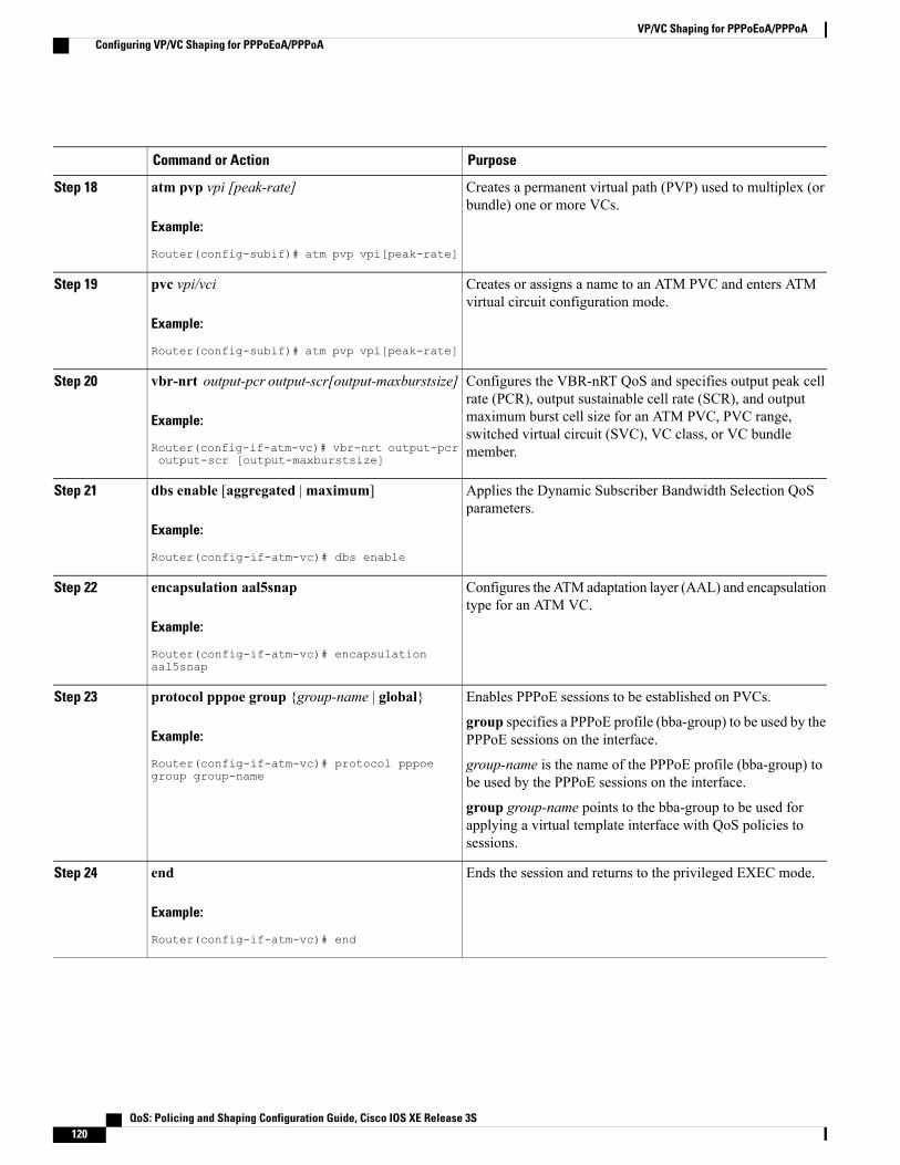
PurposeCommand or Action
Creates a permanent virtual path (PVP) used to multiplex (orbundle) one or more VCs.
atm pvp vpi [peak-rate]
Example:
Router(config-subif)# atm pvp vpi[peak-rate]
Step 18
Creates or assigns a name to an ATM PVC and enters ATMvirtual circuit configuration mode.
pvc vpi/vci
Example:
Router(config-subif)# atm pvp vpi[peak-rate]
Step 19
Configures the VBR-nRT QoS and specifies output peak cellrate (PCR), output sustainable cell rate (SCR), and output
vbr-nrt output-pcr output-scr[output-maxburstsize]
Example:
Router(config-if-atm-vc)# vbr-nrt output-pcroutput-scr [output-maxburstsize]
Step 20
maximum burst cell size for an ATM PVC, PVC range,switched virtual circuit (SVC), VC class, or VC bundlemember.
Applies the Dynamic Subscriber Bandwidth Selection QoSparameters.
dbs enable [aggregated |maximum]
Example:
Router(config-if-atm-vc)# dbs enable
Step 21
Configures the ATM adaptation layer (AAL) and encapsulationtype for an ATM VC.
encapsulation aal5snap
Example:
Router(config-if-atm-vc)# encapsulationaal5snap
Step 22
Enables PPPoE sessions to be established on PVCs.protocol pppoe group {group-name | global}Step 23
Example:
Router(config-if-atm-vc)# protocol pppoegroup group-name
group specifies a PPPoE profile (bba-group) to be used by thePPPoE sessions on the interface.
group-name is the name of the PPPoE profile (bba-group) tobe used by the PPPoE sessions on the interface.
group group-name points to the bba-group to be used forapplying a virtual template interface with QoS policies tosessions.
Ends the session and returns to the privileged EXEC mode.end
Example:
Router(config-if-atm-vc)# end
Step 24
QoS: Policing and Shaping Configuration Guide, Cisco IOS XE Release 3S120
VP/VC Shaping for PPPoEoA/PPPoAConfiguring VP/VC Shaping for PPPoEoA/PPPoA
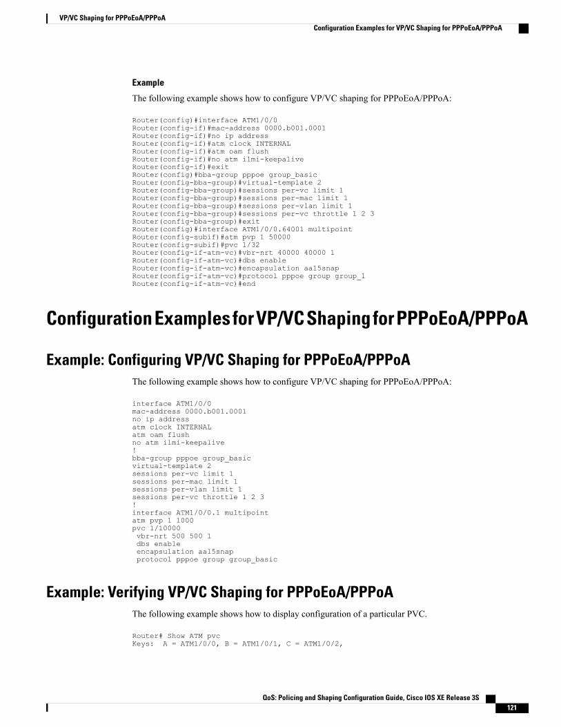
Example
The following example shows how to configure VP/VC shaping for PPPoEoA/PPPoA:
Router(config)#interface ATM1/0/0Router(config-if)#mac-address 0000.b001.0001Router(config-if)#no ip addressRouter(config-if)#atm clock INTERNALRouter(config-if)#atm oam flushRouter(config-if)#no atm ilmi-keepaliveRouter(config-if)#exitRouter(config)#bba-group pppoe group_basicRouter(config-bba-group)#virtual-template 2Router(config-bba-group)#sessions per-vc limit 1Router(config-bba-group)#sessions per-mac limit 1Router(config-bba-group)#sessions per-vlan limit 1Router(config-bba-group)#sessions per-vc throttle 1 2 3Router(config-bba-group)#exitRouter(config)#interface ATM1/0/0.64001 multipointRouter(config-subif)#atm pvp 1 50000Router(config-subif)#pvc 1/32Router(config-if-atm-vc)#vbr-nrt 40000 40000 1Router(config-if-atm-vc)#dbs enableRouter(config-if-atm-vc)#encapsulation aal5snapRouter(config-if-atm-vc)#protocol pppoe group group_1Router(config-if-atm-vc)#end
Configuration Examples for VP/VC Shaping for PPPoEoA/PPPoA
Example: Configuring VP/VC Shaping for PPPoEoA/PPPoAThe following example shows how to configure VP/VC shaping for PPPoEoA/PPPoA:
interface ATM1/0/0mac-address 0000.b001.0001no ip addressatm clock INTERNALatm oam flushno atm ilmi-keepalive!bba-group pppoe group_basicvirtual-template 2sessions per-vc limit 1sessions per-mac limit 1sessions per-vlan limit 1sessions per-vc throttle 1 2 3!interface ATM1/0/0.1 multipointatm pvp 1 1000pvc 1/10000vbr-nrt 500 500 1dbs enableencapsulation aal5snapprotocol pppoe group group_basic
Example: Verifying VP/VC Shaping for PPPoEoA/PPPoAThe following example shows how to display configuration of a particular PVC.
Router# Show ATM pvcKeys: A = ATM1/0/0, B = ATM1/0/1, C = ATM1/0/2,
QoS: Policing and Shaping Configuration Guide, Cisco IOS XE Release 3S 121
VP/VC Shaping for PPPoEoA/PPPoAConfiguration Examples for VP/VC Shaping for PPPoEoA/PPPoA

VCD / Peak Av/Min BurstInterface Name VPI VCI Type Encaps SC Kbps Kbps Cells StA.64001 1 1 3 PVC F4-OAM UBR 50000 UPA.64001 2 1 4 PVC F4-OAM UBR 50000 UPA.64001 11 1 32 PVC SNAP VBR 40000 40000 1 UPA.64001 12 1 33 PVC SNAP VBR 40000 40000 1 UPA.64001 13 1 34 PVC SNAP VBR 40000 40000 1 UPA.64001 14 1 35 PVC SNAP VBR 40000 40000 1 UPA.64001 15 1 36 PVC SNAP VBR 40000 40000 1 UPA.64001 16 1 37 PVC SNAP VBR 40000 40000 1 UPA.64001 17 1 38 PVC SNAP VBR 40000 40000 1 UPA.64001 18 1 39 PVC SNAP VBR 40000 40000 1 UPA.64001 19 1 40 PVC SNAP VBR 40000 40000 1 UPA.64001 20 1 41 PVC SNAP VBR 40000 40000 1 UPA.64001 3 2 3 PVC F4-OAM UBR 50000 UPA.64001 4 2 4 PVC F4-OAM UBR 50000 UPA.64001 21 2 32 PVC SNAP VBR 40000 40000 1 UPA.64001 22 2 33 PVC SNAP VBR 40000 40000 1 UPA.64001 23 2 34 PVC SNAP VBR 40000 40000 1 UPA.64001 24 2 35 PVC SNAP VBR 40000 40000 1 UPThe following example shows how to display configuration of the traffic parameters for a PVC.
Router# Show ATM vcKeys: A = ATM1/0/0, B = ATM1/0/1, C = ATM1/0/2,Codes: DN - DOWN, IN - INACTIVE
VCD / Peak Av/Min BurstInterface Name VPI VCI Type Encaps SC Kbps Kbps Cells StA.64001 1 1 3 PVC F4-OAM UBR 50000 UPA.64001 2 1 4 PVC F4-OAM UBR 50000 UPA.64001 11 1 32 PVC SNAP VBR 40000 40000 1 UPA.64001 12 1 33 PVC SNAP VBR 40000 40000 1 UPA.64001 13 1 34 PVC SNAP VBR 40000 40000 1 UPA.64001 14 1 35 PVC SNAP VBR 40000 40000 1 UPA.64001 15 1 36 PVC SNAP VBR 40000 40000 1 UPA.64001 16 1 37 PVC SNAP VBR 40000 40000 1 UPA.64001 17 1 38 PVC SNAP VBR 40000 40000 1 UPA.64001 18 1 39 PVC SNAP VBR 40000 40000 1 UPA.64001 19 1 40 PVC SNAP VBR 40000 40000 1 UPA.64001 20 1 41 PVC SNAP VBR 40000 40000 1 UPA.64001 3 2 3 PVC F4-OAM UBR 50000 UPA.64001 4 2 4 PVC F4-OAM UBR 50000 UPA.64001 21 2 32 PVC SNAP VBR 40000 40000 1 UPA.64001 22 2 33 PVC SNAP VBR 40000 40000 1 UPA.64001 23 2 34 PVC SNAP VBR 40000 40000 1 UPA.64001 24 2 35 PVC SNAP VBR 40000 40000 1 UPA.64001 25 2 36 PVC SNAP VBR 40000 40000 1 UPA.64001 26 2 37 PVC SNAP VBR 40000 40000 1 UPA.64001 27 2 38 PVC SNAP VBR 40000 40000 1 UPA.64001 28 2 39 PVC SNAP VBR 40000 40000 1 UPThe following example shows how to display configuration for VP mode cell relay.
Router# Show ATM vpKeys: A = ATM1/0/0, B = ATM1/0/1, C = ATM1/0/2,
Data CES Peak CES Avg/Min Burst MCRInterface VPI SC VCs VCs Kbps Kbps Kbps Cells Kbps CDVT StatusA.64001 1 VBR-NRT 10 0 50000 0 N/A N/A N/A N/A ACTIVE
A.64001 2 VBR-NRT 10 0 50000 0 N/A N/A N/A N/A ACTIVE
A.64001 3 VBR-NRT 10 0 50000 0 N/A N/A N/A N/A ACTIVE
A.64001 4 VBR-NRT 10 0 50000 0 N/A N/A N/A N/A ACTIVE
A.64001 5 VBR-NRT 10 0 50000 0 N/A N/A N/A N/A ACTIVE
B.64001 6 VBR-NRT 10 0 40000 0 N/A N/A N/A N/A ACTIVE
B.64001 7 VBR-NRT 10 0 40000 0 N/A N/A N/A N/A ACTIVE
B.64001 8 VBR-NRT 10 0 40000 0 N/A N/A N/A N/A ACTIVE
QoS: Policing and Shaping Configuration Guide, Cisco IOS XE Release 3S122
VP/VC Shaping for PPPoEoA/PPPoAExample: Verifying VP/VC Shaping for PPPoEoA/PPPoA

B.64001 9 VBR-NRT 10 0 40000 0 N/A N/A N/A N/A ACTIVE
B.64001 10 VBR-NRT 10 0 40000 0 N/A N/A N/A N/A ACTIVE
C.64001 11 VBR-NRT 10 0 30000 0 N/A N/A N/A N/A ACTIVE
C.64001 12 VBR-NRT 10 0 30000 0 N/A N/A N/A N/A ACTIVE
C.64001 13 VBR-NRT 10 0 30000 0 N/A N/A N/A N/A ACTIVE
C.64001 14 VBR-NRT 10 0 30000 0 N/A N/A N/A N/A ACTIVE
C.64001 15 VBR-NRT 10 0 30000 0 N/A N/A N/A N/A ACTIVE
Additional ReferencesRelated Documents
Document TitleRelated Topic
Cisco IOS Master Commands List, All ReleasesCisco IOS commands
Cisco IOS QoS Command ReferenceQoS commands
Technical Assistance
LinkDescription
http://www.cisco.com/cisco/web/support/index.htmlThe Cisco Support and Documentation websiteprovides online resources to download documentation,software, and tools. Use these resources to install andconfigure the software and to troubleshoot and resolvetechnical issues with Cisco products and technologies.Access to most tools on the Cisco Support andDocumentation website requires a Cisco.com user IDand password.
QoS: Policing and Shaping Configuration Guide, Cisco IOS XE Release 3S 123
VP/VC Shaping for PPPoEoA/PPPoAAdditional References

Feature Information for VP/VC Shaping for PPPoEoA/PPPoATable 12: Feature Information for VP/VC Shaping for PPPoEoA/PPPoA
Feature InformationReleasesFeature Name
VP/VC Shaping forPPPoEoA/PPPoA enables ATMVP shaping for VCs withunderlying broadband sessions.
Cisco IOS XE Release 3.10VP/VC Shaping forPPPoEoA/PPPoA
Cisco and the Cisco Logo are trademarks of Cisco Systems, Inc. and/or its affiliates in the U.S. and othercountries. A listing of Cisco's trademarks can be found at www.cisco.com/go/trademarks. Third party trademarksmentioned are the property of their respective owners. The use of the word partner does not imply a partnershiprelationship between Cisco and any other company. (1005R)
QoS: Policing and Shaping Configuration Guide, Cisco IOS XE Release 3S124
VP/VC Shaping for PPPoEoA/PPPoAFeature Information for VP/VC Shaping for PPPoEoA/PPPoA

C H A P T E R 10Hierarchical Color-Aware Policing
The Hierarchical Color-Aware Policing feature provides two levels of policing where the policer orderingis evaluated from child to parent, and there is preferential treatment of certain traffic at the parent level.Beginning in Cisco IOS XE Release 3.2S, this feature is enabled on the Cisco ASR 1000 series AggregationServices Routers through the following support and changes:
• Reverse the order of dataplane policing in hierarchical policies so that they are evaluated from childto parent. In prior releases, the policies are evaluated from parent to child.
• Limited support for color-aware policing (RFC 2697 and RFC 2698) within Quality of Service (QoS)policies.
• Finding Feature Information, page 125
• Prerequisites for Hierarchical Color-Aware Policing, page 126
• Restrictions for Hierarchical Color-Aware Policing, page 126
• Information About Hierarchical Color-Aware Policing, page 126
• How to Configure Hierarchical Color-Aware Policing, page 130
• Configuration Examples for Hierarchical Color-Aware Policing, page 132
• Additional References, page 136
• Feature Information for Hierarchical Color-Aware Policing, page 137
Finding Feature InformationYour software release may not support all the features documented in this module. For the latest caveats andfeature information, see Bug Search Tool and the release notes for your platform and software release. Tofind information about the features documented in this module, and to see a list of the releases in which eachfeature is supported, see the feature information table at the end of this module.
Use Cisco Feature Navigator to find information about platform support and Cisco software image support.To access Cisco Feature Navigator, go to www.cisco.com/go/cfn. An account on Cisco.com is not required.
QoS: Policing and Shaping Configuration Guide, Cisco IOS XE Release 3S 125

Prerequisites for Hierarchical Color-Aware PolicingYou must have Cisco IOS XE Release 3.2S or a later version installed and running on your Cisco ASR 1000series router.
You must already be familiar with relevant features and technologies including modular QoS CLI (MQC)and the master control processor (MCP) software and hardware architecture. The Additional References, onpage 136 section provides pointers to relevant feature and technology documents.
Restrictions for Hierarchical Color-Aware PolicingThe following restrictions apply to the Hierarchical Color-Aware Policing feature:
• Color-aware class maps support only QoS group matching.
• Only one filter (one match statement) per color-aware class is supported.
• Color-aware statistics are not supported, only existing policer statistics.
• Color-aware class map removal (using the no class-mapclass-map-name command) is not allowed whilethe class map is being referenced in a color-aware policer. It must be removed from all color-awarepolicers (using either the no conform-colorclass-map-name or no exceed-colorclass-map-name commandfirst).
• Hierarchical policer evaluation is permanently reversed (not configurable) to support child-to-parentordering.
Information About Hierarchical Color-Aware Policing
Hierarchical Order PolicingPrior to Cisco IOS XE Release 3.2S, the Cisco ASR 1000 series platform supported policers in hierarchicalpolicies with an evaluation order of parent to child. With the introduction of the Hierarchical Color-AwarePolicing feature, the evaluation order is reversed so that policers are evaluated from child to parent in QoSpolicies. This ordering is a permanent change to the default behavior and is not configurable. The reverseorder policer functionality is shared for both ingress and egress directions.
The following sample configuration for a simple two-level policer would result in the changed behavior shownin the figure below:
policy-map childclass user1police 100kclass user2police 100k
policy-map parentclass class-defaultpolice 150kservice-policy child
QoS: Policing and Shaping Configuration Guide, Cisco IOS XE Release 3S126
Hierarchical Color-Aware PolicingPrerequisites for Hierarchical Color-Aware Policing
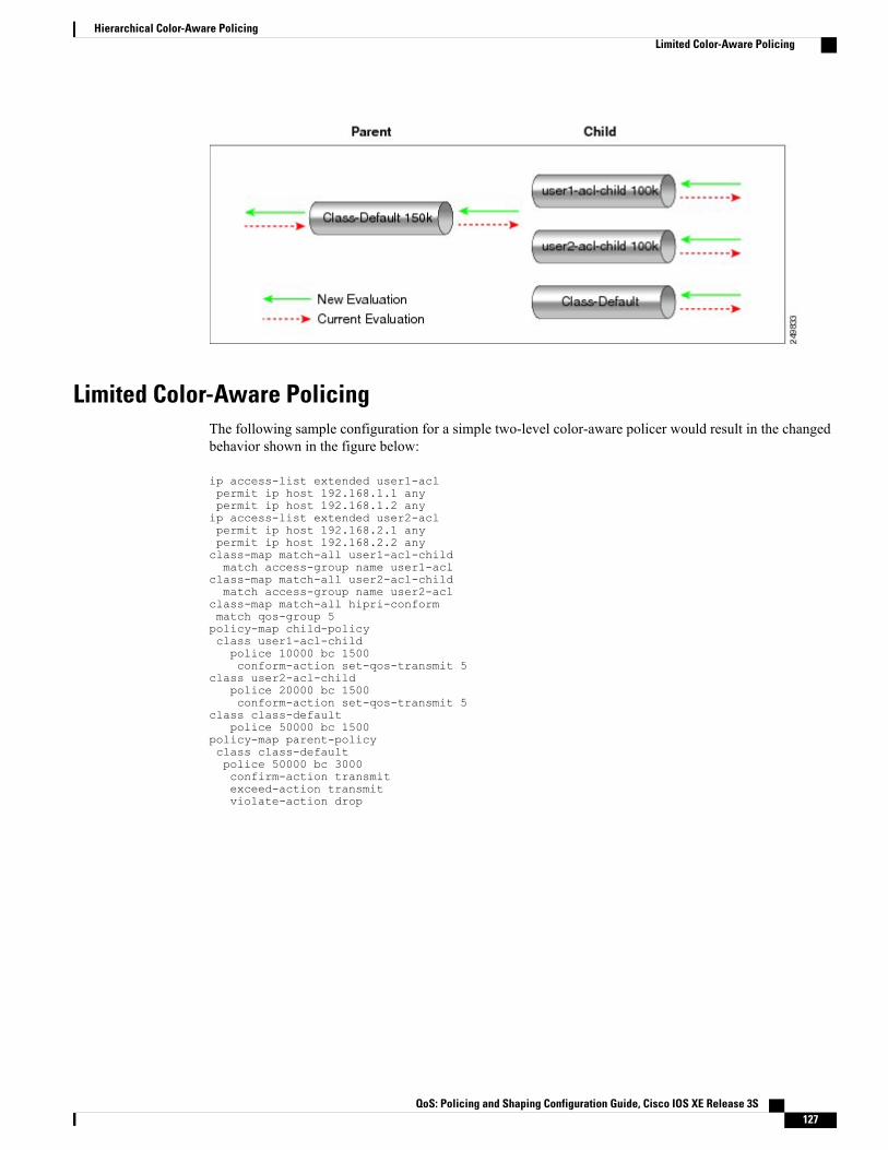
Limited Color-Aware PolicingThe following sample configuration for a simple two-level color-aware policer would result in the changedbehavior shown in the figure below:
ip access-list extended user1-aclpermit ip host 192.168.1.1 anypermit ip host 192.168.1.2 anyip access-list extended user2-aclpermit ip host 192.168.2.1 anypermit ip host 192.168.2.2 anyclass-map match-all user1-acl-childmatch access-group name user1-acl
class-map match-all user2-acl-childmatch access-group name user2-acl
class-map match-all hipri-conformmatch qos-group 5policy-map child-policyclass user1-acl-childpolice 10000 bc 1500conform-action set-qos-transmit 5
class user2-acl-childpolice 20000 bc 1500conform-action set-qos-transmit 5
class class-defaultpolice 50000 bc 1500
policy-map parent-policyclass class-defaultpolice 50000 bc 3000confirm-action transmitexceed-action transmitviolate-action drop
QoS: Policing and Shaping Configuration Guide, Cisco IOS XE Release 3S 127
Hierarchical Color-Aware PolicingLimited Color-Aware Policing
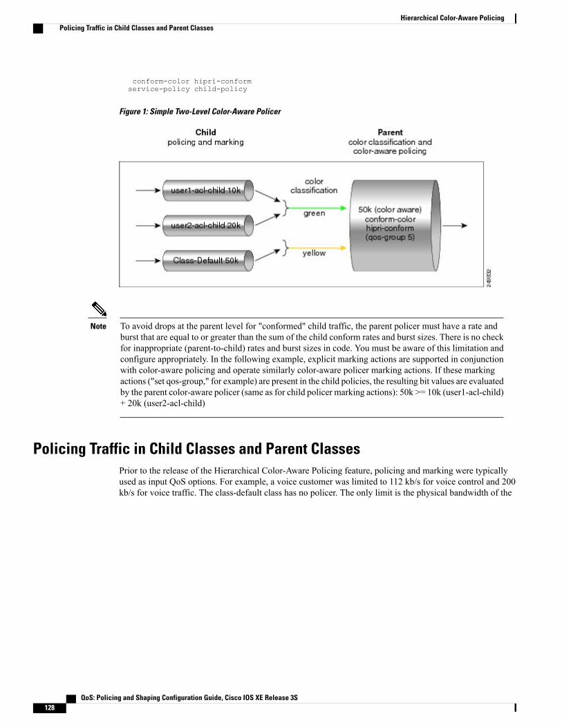
conform-color hipri-conformservice-policy child-policy
Figure 1: Simple Two-Level Color-Aware Policer
To avoid drops at the parent level for "conformed" child traffic, the parent policer must have a rate andburst that are equal to or greater than the sum of the child conform rates and burst sizes. There is no checkfor inappropriate (parent-to-child) rates and burst sizes in code. You must be aware of this limitation andconfigure appropriately. In the following example, explicit marking actions are supported in conjunctionwith color-aware policing and operate similarly color-aware policer marking actions. If these markingactions ("set qos-group," for example) are present in the child policies, the resulting bit values are evaluatedby the parent color-aware policer (same as for child policer marking actions): 50k >= 10k (user1-acl-child)+ 20k (user2-acl-child)
Note
Policing Traffic in Child Classes and Parent ClassesPrior to the release of the Hierarchical Color-Aware Policing feature, policing and marking were typicallyused as input QoS options. For example, a voice customer was limited to 112 kb/s for voice control and 200kb/s for voice traffic. The class-default class has no policer. The only limit is the physical bandwidth of the
QoS: Policing and Shaping Configuration Guide, Cisco IOS XE Release 3S128
Hierarchical Color-Aware PolicingPolicing Traffic in Child Classes and Parent Classes

xDSL connection. As shown in the figure below, a customer could send up to 1000 kb/s. However, thisinvolved sending more voice and voice-control packets, which required policing the traffic for both classes.
Figure 2: Policing Traffic in Child Classes
As shown in the figure below, it is important to control the overall input bandwidth. The important requirementis that the premium traffic in the overall limit is not affected. In the figure below, voice and voice-controlpackets are not dropped in the overall limit. Only packets from the child class-default class are dropped tofulfill the limit.
Figure 3: Policing Traffic in Parent Classes
The first classes function the same way. Voice and voice-control are policed to the allowed level and theclass-default class is not affected. In the next level, the overall bandwidth is forced to 500 kb/s and must onlydrop packets from the class-default class. Voice and voice-control must remain unaffected.
The order of policer execution is as follows:
1 Police the traffic in the child classes, as shown in the figure above, police VoIP-Control class to 112 kb/s,police VoIP class to 200 kb/s, and police class-default to 500 kb/s.
2 Police the traffic in the class default of the parent policy map, but only drop the traffic from the child classdefault, and do not drop the remaining child classes. As shown in the figure above, 112 kb/s VoIP-Controland 200 kb/s VoIP traffic are unaffected at the parent policer, but 500 kb/s class default from the child ispoliced to 188kb/s to meet the overall police policy of 500 kb/s at the parent level.
QoS: Policing and Shaping Configuration Guide, Cisco IOS XE Release 3S 129
Hierarchical Color-Aware PolicingPolicing Traffic in Child Classes and Parent Classes

How to Configure Hierarchical Color-Aware Policing
Configuring the Hierarchical Color-Aware Policing Feature
SUMMARY STEPS
1. enable2. configure terminal3. policy-map policy-map-name4. class {class-name | class-default [fragment fragment-class-name]} [insert-before class-name]
[service-fragment fragment-class-name]5. police [cir cir][bc conform-burst] [pir pir][be peak-burst] [conform-action action [exceed-action action
[violate-action action]]][conform-color hipri-conform]6. service-policy policy-map-name7. end
DETAILED STEPS
PurposeCommand or Action
Enables privileged EXEC mode.enableStep 1
Example:
Router> enable
• Enter your password if prompted.
Enters global configuration mode.configure terminal
Example:
Router# configure terminal
Step 2
Enters policy-map configuration mode and creates a policy map.policy-map policy-map-name
Example:
Router(config)# policy-mapparent-policy
Step 3
Enters policy-map class configuration mode.class {class-name | class-default[fragment fragment-class-name]}
Step 4
• Specifies the name of the class whose policy you want to create or changeor specifies the default class (commonly known as the class-default class)
[insert-before class-name][service-fragment fragment-class-name]
before you configure its policy. Repeat this command as many times as
QoS: Policing and Shaping Configuration Guide, Cisco IOS XE Release 3S130
Hierarchical Color-Aware PolicingHow to Configure Hierarchical Color-Aware Policing

PurposeCommand or Action
Example:
Router(config-pmap)# classclass-default
necessary to specify the child or parent classes that you are creating ormodifying:
• class name --Name of the class to be configured or whose policy is to bemodified. The class name is used for both the class map and to configurea policy for the class in the policy map.
• class-default --Specifies the default class so that you can configure ormodify its policy.
• fragment fragment-class-name --(Optional) Specifies the default trafficclass as a fragment, and names the fragment traffic class.
• insert-before class-name --(Optional) Adds a class map between anytwo existing class maps. Inserting a new class map between two existingclass maps provides more flexibility whenmodifying existing policy mapconfigurations. Without this option, the class map is appended to thepolicy map.
This keyword is supported only on flexible packet matching (FPM)policies.
Note
• service-fragment fragment-class-name --(Optional) Specifies that theclass is classifying a collection of fragments. The fragments beingclassified by this class must all share the same fragment class name.
Configures traffic policing and specifies multiple actions applied to packetsmarked as conforming to, exceeding, or violating a specific rate.
police [cir cir][bc conform-burst] [pirpir][be peak-burst] [conform-action action
Step 5
[exceed-action action [violate-actionaction]]][conform-color hipri-conform] • Enters policy-map class police configuration mode. Use one line per
action that you want to specify:
Example:
Router(config-pmap-c)# police 50000
• cir --Committed information rate. Indicates that the CIR will be used forpolicing traffic.
bc 3000 • conform-action --(Optional) Action to take on packets when the rate isless than the conform burst.Router(config-pmap-c-police)#
exceed-action transmit
Example:
Router(config-pmap-c-police)#violate-action drop
• exceed-action --(Optional) Action to take on packets whose rate is withinthe conform and conform plus exceed burst.
• violate-action --(Optional) Action to take on packets whose rate exceedsthe conform plus exceed burst. You must specify the exceed action beforeyou specify the violate action.
Example:
Router(config-pmap-c-police)#conform-color hipri-conform
• conform-color --(Optional) Enables color-aware policing (on the policerbeing configured) and assigns the class map to be used for conform colordetermination. The hipri-conform keyword is the class map (previouslyconfigured via the class-map command) to be used.
QoS: Policing and Shaping Configuration Guide, Cisco IOS XE Release 3S 131
Hierarchical Color-Aware PolicingConfiguring the Hierarchical Color-Aware Policing Feature

PurposeCommand or Action
Specifies a service policy as a QoS policy within a policy map (called ahierarchical service policy).
service-policy policy-map-name
Example:
Router(config-pmap-c-police)#service-policy child-policy
Step 6
• policy-map-name --Name of the predefined policy map to be used as aQoS policy. The name can be a maximum of 40 alphanumeric characters.
Exits the current configuration mode.end
Example:
Router(config-pmap-c-police)# end
Step 7
Example
The following is a sample configuration for the Hierarchical Color-Aware Policing feature, showing thereverse order for policing:
class-map match-all user1-acl-childmatch access-group name user1-aclclass-map match-all user2-acl-childmatch access-group name user2-aclclass-map match-all hipri-conformmatch qos-group 5policy-map child-policyclass user1-acl-childpolice 10000 bc 1500conform-action set-qos-transmit 5class user2-acl-childpolice 20000 bc 1500conform-action set-qos-transmit 5class class-defaultpolice 50000 bc 1500policy-map parent-policyclass class-defaultpolice 50000 bc 3000exceed-action transmitviolate-action dropconform-color hipri-conformservice-policy child-policy
Configuration Examples for Hierarchical Color-Aware Policing
Example Enable the Hierarchical Color-Aware Policing FeatureThe following example shows a sample configuration that enables the Hierarchical Color-Aware Policingfeature:
Router# configure terminalEnter configuration commands, one per line. End with CNTL/Z.Router(config)# ip access-list extended user1-aclRouter(config-ext-nacl)# permit ip host 192.168.1.1 any
QoS: Policing and Shaping Configuration Guide, Cisco IOS XE Release 3S132
Hierarchical Color-Aware PolicingConfiguration Examples for Hierarchical Color-Aware Policing

Router(config-ext-nacl)# permit ip host 192.168.1.2 anyRouter(config-ext-nacl)# ip access-list extended user2-aclRouter(config-ext-nacl)# permit ip host 192.168.2.1 anyRouter(config-ext-nacl)# permit ip host 192.168.2.2 anyRouter(config-ext-nacl)# exitRouter(config)# class-map match-all user1-acl-childRouter(config-cmap)# match access-group name user1-aclRouter(config-cmap)# class-map match-all user2-acl-childRouter(config-cmap)# match access-group name user2-aclRouter(config-cmap)# class-map match-all hipri-conformRouter(config-cmap)# match qos-group 5Router(config-cmap)# exitRouter(config)# policy-map child-policyRouter(config-pmap)# class user1-acl-childRouter(config-pmap-c)# police cir 10000 bc 1500Router(config-pmap-c-police)# class user2-acl-childRouter(config-pmap-c)# police cir 20000 bc 1500Router(config-pmap-c-police)# exitRouter(config-pmap-c)# exitRouter(config-pmap)# exitRouter(config)# policy-map parent-policyRouter(config-pmap)# class class-defaultRouter(config-pmap-c)# police cir 50000 bc 3000Router(config-pmap-c-police)# exceed-action transmitRouter(config-pmap-c-police)# violate-action dropRouter(config-pmap-c-police)# conform-color hipri-conformRouter(config-pmap-c-police)# service-policy child-policy
Example Disallowing Multiple Entries in Class MapThe following example shows a rejected attempt to configure multiple entries in a class map:
Router# configure terminalEnter configuration commands, one per line. End with CNTL/Z.Router(config)# class-map hipri-conformRouter(config-cmap)# match qos-group 5Router(config-cmap)# match qos-group 6Only one match statement is supported for color-aware policingRouter(config-cmap)# no match qos-group 6
Example Disallowing the Removal of an Active Color-Aware Class MapThe following example shows that an active color-aware class map cannot be disallowed:
Router# configure terminalEnter configuration commands, one per line. End with CNTL/Z.Router(config)# no class-map hipri-conformClass-map hipri-conform is being used
Example Dismantling a Configuration of the Hierarchical Color-Aware PolicingFeature
The following example shows how to dismantle the configuration of the Hierarchical Color-Aware Policingfeature:
Router# configure terminalEnter configuration commands, one per line. End with CNTL/Z.Router(config)# no policy-map parent-policy
QoS: Policing and Shaping Configuration Guide, Cisco IOS XE Release 3S 133
Hierarchical Color-Aware PolicingExample Disallowing Multiple Entries in Class Map
Router(config)# no policy-map child-policyRouter(config)# no class-map hipri-conformRouter(config)# no class-map user1-acl-childRouter(config)# no class-map user2-acl-child
Example Enabling Hierarchical Color-Aware PolicingThe following example shows how to enable Hierarchical Color-Aware Policing:
Router# configure terminalEnter configuration commands, one per line. End with CNTL/Z.Router(config)# ip access-list extended user1-aclRouter(config-ext-nacl)# permit ip host 192.168.1.1 anyRouter(config-ext-nacl)# permit ip host 192.168.1.2 anyRouter(config-ext-nacl)# ip access-list extended user2-aclRouter(config-ext-nacl)# permit ip host 192.168.2.1 anyRouter(config-ext-nacl)# permit ip host 192.168.2.2 anyRouter(config-ext-nacl)# class-map match-all user1-acl-childRouter(config-cmap)# match access-group name user1-aclRouter(config-cmap)# class-map match-all user2-acl-childRouter(config-cmap)# match access-group name user2-aclRouter(config-cmap)# class-map match-all hipri-conformRouter(config-cmap)# match qos-group 5Router(config-cmap)# policy-map child-policyRouter(config-pmap)# class user1-acl-childRouter(config-pmap-c)# police 10000 bc 1500Router(config-pmap-c-police)# conform-action set-qos-transmit 5Router(config-pmap-c-police)# class user2-acl-childRouter(config-pmap-c)# police 20000 bc 1500Router(config-pmap-c-police)# conform-action set-qos-transmit 5Router(config-pmap-c-police)# class class-defaultRouter(config-pmap-c)# police 50000 bc 1500Router(config-pmap-c-police)# policy-map parent-policyRouter(config-pmap)# class class-defaultRouter(config-pmap-c)# police 50000 bc 3000Router(config-pmap-c-police)# exceed-action transmitRouter(config-pmap-c-police)# violate-action dropRouter(config-pmap-c-police)# conform-color hipri-conformRouter(config-pmap-c-police)# service-policy child-policyRouter(config-pmap-c)# endRouter#*Sep 16 12:31:11.536: %SYS-5-CONFIG_I: Configured from console by consoleRouter# show class-mapClass Map match-all user1-acl-child (id 4)Match access-group name user1-aclClass Map match-all user2-acl-child (id 5)Match access-group name user2-aclClass Map match-any class-default (id 0)Match anyClass Map match-all hipri-conform (id 3)Match qos-group 5Router# show policy-mapPolicy Map parent-policyClass class-defaultpolice cir 50000 bc 3000 be 3000conform-color hipri-conformconform-action transmitexceed-action transmitviolate-action dropservice-policy child-policyPolicy Map policeClass prec1priority level 1 20000 (kb/s)Class prec2bandwidth 20000 (kb/s)Class class-defaultbandwidth 20000 (kb/s)Policy Map child-policy
QoS: Policing and Shaping Configuration Guide, Cisco IOS XE Release 3S134
Hierarchical Color-Aware PolicingExample Enabling Hierarchical Color-Aware Policing

Class user1-acl-childpolice cir 10000 bc 1500conform-action set-qos-transmit 5exceed-action dropClass user2-acl-childpolice cir 20000 bc 1500conform-action set-qos-transmit 5exceed-action dropClass class-defaultpolice cir 50000 bc 1500conform-action transmitexceed-action drop
Example Applying show Command with Hierarchical Color-Aware PolicingThe following is sample output from the show policy-map interface commandwhen a policy with hierarchicalcolor-aware policing is applied:
Router# show policy-map interfaceGigabitEthernet0/0/0Service-policy input: parent-policyClass-map: class-default (match-any)0 packets, 0 bytes5 minute offered rate 0000 bps, drop rate 0000 bpsMatch: anypolice:cir 50000 bps, bc 3000 bytes, be 3000 bytesconformed 0 packets, 0 bytes; actions:transmitexceeded 0 packets, 0 bytes; actions:transmitviolated 0 packets, 0 bytes; actions:dropNo color-aware policing statistics availableconformed 0000 bps, exceed 0000 bps, violate 0000 bpsService-policy : child-policyClass-map: user1-acl-child (match-all)0 packets, 0 bytes5 minute offered rate 0000 bps, drop rate 0000 bpsMatch: access-group name user1-aclpolice:cir 10000 bps, bc 1500 bytesconformed 0 packets, 0 bytes; actions:set-qos-transmit 5exceeded 0 packets, 0 bytes; actions:dropconformed 0000 bps, exceed 0000 bpsClass-map: user2-acl-child (match-all)0 packets, 0 bytes5 minute offered rate 0000 bps, drop rate 0000 bpsMatch: access-group name user2-aclpolice:cir 20000 bps, bc 1500 bytesconformed 0 packets, 0 bytes; actions:set-qos-transmit 5exceeded 0 packets, 0 bytes; actions:dropconformed 0000 bps, exceed 0000 bpsClass-map: class-default (match-any)0 packets, 0 bytes5 minute offered rate 0000 bps, drop rate 0000 bpsMatch: anypolice:cir 50000 bps, bc 1500 bytesconformed 0 packets, 0 bytes; actions:transmitexceeded 0 packets, 0 bytes; actions:dropconformed 0000 bps, exceed 0000 bps
QoS: Policing and Shaping Configuration Guide, Cisco IOS XE Release 3S 135
Hierarchical Color-Aware PolicingExample Applying show Command with Hierarchical Color-Aware Policing

Additional ReferencesRelated Documents
Document TitleRelated Topic
Cisco IOS Master Commands List, All ReleasesCisco IOS commands
Cisco IOS Quality of Service Solutions CommandReference
Quality of Service commands
Cisco IOS QoS Configuration Guide, Cisco IOS XERelease 3S
Quality of Service configuration information
Standards
TitleStandard
--No new or modified standards are supported by thisfeature.
MIBs
MIBs LinkMIB
To locate and downloadMIBs for selected platforms,Cisco software releases, and feature sets, use CiscoMIB Locator found at the following URL:
http://www.cisco.com/go/mibs
• CISCO-CLASS-BASED-QOS-MIB
• CISCO-CLASS-BASED-QOS-CAPABILITY-MIB
RFCs
TitleRFC
A Single Rate Three Color MarkerRFC 2697
A Two Rate Three Color MarkerRFC 2698
QoS: Policing and Shaping Configuration Guide, Cisco IOS XE Release 3S136
Hierarchical Color-Aware PolicingAdditional References
Technical Assistance
LinkDescription
http://www.cisco.com/cisco/web/support/index.htmlThe Cisco Support and Documentation websiteprovides online resources to download documentation,software, and tools. Use these resources to install andconfigure the software and to troubleshoot and resolvetechnical issues with Cisco products and technologies.Access to most tools on the Cisco Support andDocumentation website requires a Cisco.com user IDand password.
Feature Information for Hierarchical Color-Aware PolicingThe following table provides release information about the feature or features described in this module. Thistable lists only the software release that introduced support for a given feature in a given software releasetrain. Unless noted otherwise, subsequent releases of that software release train also support that feature.
Use Cisco Feature Navigator to find information about platform support and Cisco software image support.To access Cisco Feature Navigator, go to www.cisco.com/go/cfn. An account on Cisco.com is not required.
Table 13: Feature Information for Hierarchical Color-Aware Policing
Feature InformationReleasesFeature Name
The Hierarchical Color-AwarePolicing feature provides for twolevels of policing where the policerordering is evaluated from child toparent, and there is preferentialtreatment of certain traffic at theparent level.
Cisco IOS XE Release 3.2SHierarchical Color-Aware Policing
QoS: Policing and Shaping Configuration Guide, Cisco IOS XE Release 3S 137
Hierarchical Color-Aware PolicingFeature Information for Hierarchical Color-Aware Policing

QoS: Policing and Shaping Configuration Guide, Cisco IOS XE Release 3S138
Hierarchical Color-Aware PolicingFeature Information for Hierarchical Color-Aware Policing

C H A P T E R 11IPv6 QoS: MQC Traffic Policing
Configuration or command usage for policing are the same in IPv6 environments as for IPv4 environments.
• Finding Feature Information, page 139
• Information About IPv6 QoS: MQC Traffic Policing, page 139
• Additional References, page 140
• Feature Information for IPv6 QoS: MQC Traffic Policing, page 141
Finding Feature InformationYour software release may not support all the features documented in this module. For the latest caveats andfeature information, see Bug Search Tool and the release notes for your platform and software release. Tofind information about the features documented in this module, and to see a list of the releases in which eachfeature is supported, see the feature information table at the end of this module.
Use Cisco Feature Navigator to find information about platform support and Cisco software image support.To access Cisco Feature Navigator, go to www.cisco.com/go/cfn. An account on Cisco.com is not required.
Information About IPv6 QoS: MQC Traffic Policing
Implementation Strategy for QoS for IPv6IPv6 packets are forwarded by paths that are different from those for IPv4. QoS features supported for IPv6environments include packet classification, queuing, traffic shaping, weighted random early detection (WRED),class-based packet marking, and policing of IPv6 packets. These features are available at both the processswitching and Cisco Express Forwarding switching paths of IPv6.
All of the QoS features available for IPv6 environments are managed from the modular QoS command-lineinterface (MQC). The MQC allows you to define traffic classes, create and configure traffic policies (policymaps), and then attach those traffic policies to interfaces.
To implement QoS in networks that are running IPv6, follow the same steps that you would follow to implementQoS in networks running only IPv4. At a very high level, the basic steps for implementing QoS are as follows:
QoS: Policing and Shaping Configuration Guide, Cisco IOS XE Release 3S 139

• Know which applications in your network need QoS.
• Understand the characteristics of the applications so that you can make decisions about which QoSfeatures would be appropriate.
• Know your network topology so that you know how link layer header sizes are affected by changes andforwarding.
• Create classes based on the criteria that you establish for your network. In particular, if the same networkis also carrying IPv4 traffic along with IPv6 traffic, decide if you want to treat both of them the sameway or treat them separately and specify match criteria accordingly. If you want to treat them the same,use match statements such asmatch precedence, match dscp, set precedence, and set dscp. If youwant to treat them separately, add match criteria such asmatch protocol ip andmatch protocol ipv6in a match-all class map.
• Create a policy to mark each class.
•Work from the edge toward the core in applying QoS features.
• Build the policy to treat the traffic.
• Apply the policy.
Traffic Policing in IPv6 EnvironmentsCongestion management for IPv6 is similar to IPv4, and the commands used to configure queueing and trafficshaping features for IPv6 environments are the same commands as those used for IPv4. Traffic shaping allowsyou to limit the packet dequeue rate by holding additional packets in the queues and forwarding them asspecified by parameters configured for traffic shaping features. Traffic shaping uses flow-based queueing bydefault. CBWFQ can be used to classify and prioritize the packets. Class-based policer and generic trafficshaping (GTS) or Frame Relay traffic shaping (FRTS) can be used for conditioning and policing traffic.
Additional ReferencesRelated Documents
Document TitleRelated Topic
Cisco IOS Quality of Service Solutions CommandReference
QoS commands: complete command syntax,command modes, command history, defaults, usageguidelines, and examples
"Applying QoS Features Using the MQC" moduleModular Quality of Service (QoS) Command-LineInterface (CLI) (MQC), hierarchical policies, policymaps
"Policing and Shaping Overview" modulePolicing and shaping traffic
QoS: Policing and Shaping Configuration Guide, Cisco IOS XE Release 3S140
IPv6 QoS: MQC Traffic PolicingTraffic Policing in IPv6 Environments

Standards
TitleStandard
--No new or modified standards are supported by thisfeature, and support for existing standards has notbeen modified by this feature.
MIBs
MIBs LinkMIB
To locate and downloadMIBs for selected platforms,Cisco IOSXE software releases, and feature sets, useCisco MIB Locator found at the following URL:
http://www.cisco.com/go/mibs
No new or modified MIBs are supported by thisfeature, and support for existing MIBs has not beenmodified by this feature.
RFCs
TitleRFC
--No new or modified RFCs are supported by thisfeature, and support for existing RFCs has not beenmodified by this feature.
Technical Assistance
LinkDescription
http://www.cisco.com/cisco/web/support/index.htmlThe Cisco Support and Documentation websiteprovides online resources to download documentation,software, and tools. Use these resources to install andconfigure the software and to troubleshoot and resolvetechnical issues with Cisco products and technologies.Access to most tools on the Cisco Support andDocumentation website requires a Cisco.com user IDand password.
Feature Information for IPv6 QoS: MQC Traffic PolicingThe following table provides release information about the feature or features described in this module. Thistable lists only the software release that introduced support for a given feature in a given software releasetrain. Unless noted otherwise, subsequent releases of that software release train also support that feature.
QoS: Policing and Shaping Configuration Guide, Cisco IOS XE Release 3S 141
IPv6 QoS: MQC Traffic PolicingFeature Information for IPv6 QoS: MQC Traffic Policing

Use Cisco Feature Navigator to find information about platform support and Cisco software image support.To access Cisco Feature Navigator, go to www.cisco.com/go/cfn. An account on Cisco.com is not required.
Table 14: Feature Information for IPv6 QoS: MQC Traffic Policing
Feature InformationReleasesFeature Name
Configuration or command usagefor policing are the same in IPv6environments as for IPv4environments.
Cisco IOS XE Release 2.1IPv6 QoS: MQC Traffic Policing
QoS: Policing and Shaping Configuration Guide, Cisco IOS XE Release 3S142
IPv6 QoS: MQC Traffic PolicingFeature Information for IPv6 QoS: MQC Traffic Policing

C H A P T E R 12Traffic Policing
This feature module describes the Traffic Policing feature. The Traffic Policing feature performs the followingfunctions:
• Limits the input or output transmission rate of a class of traffic based on user-defined criteria.
• Marks packets by setting the ATM Cell Loss Priority (CLP) bit, Frame Relay Discard Eligibility (DE)bit, IP precedence value, IP differentiated services code point (DSCP) value, MPLS experimental value,and Quality of Service (QoS) group.
Traffic policing allows you to control the maximum rate of traffic that is transmitted or received on aninterface. The Traffic Policing feature is applied when a service-policy containing the feature is attached toan interface. A service-policy (traffic policy) is configured using the Modular Quality of Service (QoS)Command-Line Interface (CLI) (MQC).
• Finding Feature Information, page 143
• Restrictions for Traffic Policing, page 144
• Benefits, page 144
• How to Configure Traffic Policing, page 145
• Configuration Examples for Traffic Policing, page 145
• Additional References, page 146
• Feature Information for Traffic Policing, page 147
Finding Feature InformationYour software release may not support all the features documented in this module. For the latest caveats andfeature information, see Bug Search Tool and the release notes for your platform and software release. Tofind information about the features documented in this module, and to see a list of the releases in which eachfeature is supported, see the feature information table at the end of this module.
Use Cisco Feature Navigator to find information about platform support and Cisco software image support.To access Cisco Feature Navigator, go to www.cisco.com/go/cfn. An account on Cisco.com is not required.
QoS: Policing and Shaping Configuration Guide, Cisco IOS XE Release 3S 143

Restrictions for Traffic Policing• Traffic policing can be configured on an interface or a subinterface.
• Traffic policing is not supported on the EtherChannel interfaces.
BenefitsBandwidth Management Through Rate Limiting
Traffic policing allows you to control the maximum rate of traffic transmitted or received on an interface.Traffic policing is often configured on interfaces at the edge of a network to limit traffic into or out of thenetwork. In most Traffic Policing configurations, traffic that falls within the rate parameters is transmitted,whereas traffic that exceeds the parameters is dropped or transmitted with a different priority.
Packet Marking
Packet marking allows you to partition your network into multiple priority levels or classes of service (CoS).A packet is marked and these markings can be used to identify and classify traffic for downstream devices.In some cases, such as ATM Cell Loss Priority (CLP) marking or Frame Relay Discard Eligibility (DE)marking, the marking is used to classify traffic.
• Use traffic policing to set the IP precedence or DSCP values for packets entering the network. Networkingdevices within your network can then use the adjusted IP precedence values to determine how the trafficshould be treated. For example, the Weighted Random Early Detection (WRED) feature uses the IPprecedence values to determine the probability that a packet will be dropped.
• Use traffic policing to assign packets to a QoS group. The router uses the QoS group to determine howto prioritize packets within the router.
Traffic can be marked without using the Traffic Policing feature. If you want to mark traffic but do not wantto use Traffic Policing, see the "Marking Network Traffic" module.
Packet Prioritization for Frame Relay Frames
The Traffic Policing feature allows users to mark the Frame Relay DE bit of the Frame Relay frame. TheFrame Relay DE bit is one bit and, therefore, can be set to either 0 or 1. In congested environments, frameswith the DE bit set to 1 are discarded before frames with the DE bit set to 0.
Packet Prioritization for ATM Cells
The Traffic Policing feature allows users to mark the ATM CLP bit in ATM cells. The ATM CLP bit is usedto prioritize packets in ATM networks. The ATM CLP bit is one bit and, therefore, can be set to either 0 or1. In congested environments, cells with the ATM CLP bit set to 1 are discarded before cells with the ATMCLP bit set to 0.
QoS: Policing and Shaping Configuration Guide, Cisco IOS XE Release 3S144
Traffic PolicingRestrictions for Traffic Policing
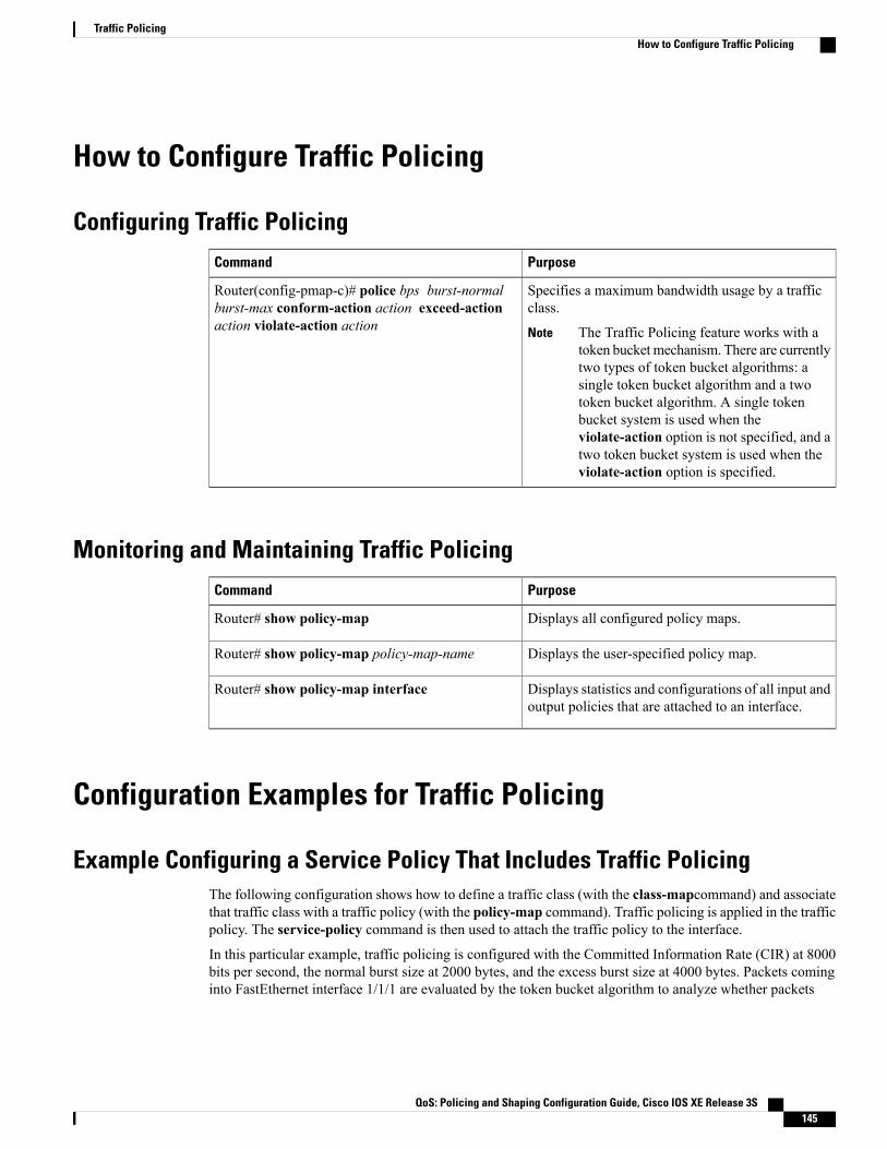
How to Configure Traffic Policing
Configuring Traffic PolicingPurposeCommand
Specifies a maximum bandwidth usage by a trafficclass.
The Traffic Policing feature works with atoken bucket mechanism. There are currentlytwo types of token bucket algorithms: asingle token bucket algorithm and a twotoken bucket algorithm. A single tokenbucket system is used when theviolate-action option is not specified, and atwo token bucket system is used when theviolate-action option is specified.
Note
Router(config-pmap-c)# police bps burst-normalburst-max conform-action action exceed-actionaction violate-action action
Monitoring and Maintaining Traffic PolicingPurposeCommand
Displays all configured policy maps.Router# show policy-map
Displays the user-specified policy map.Router# show policy-map policy-map-name
Displays statistics and configurations of all input andoutput policies that are attached to an interface.
Router# show policy-map interface
Configuration Examples for Traffic Policing
Example Configuring a Service Policy That Includes Traffic PolicingThe following configuration shows how to define a traffic class (with the class-mapcommand) and associatethat traffic class with a traffic policy (with the policy-map command). Traffic policing is applied in the trafficpolicy. The service-policy command is then used to attach the traffic policy to the interface.
In this particular example, traffic policing is configured with the Committed Information Rate (CIR) at 8000bits per second, the normal burst size at 2000 bytes, and the excess burst size at 4000 bytes. Packets cominginto FastEthernet interface 1/1/1 are evaluated by the token bucket algorithm to analyze whether packets
QoS: Policing and Shaping Configuration Guide, Cisco IOS XE Release 3S 145
Traffic PolicingHow to Configure Traffic Policing

conform exceed, or violate the specified parameters. Packets that conform are transmitted, packets that exceedare assigned a QoS group value of 4 and are transmitted, and packets that violate are dropped.
Router(config)# class-map acgroup2Router(config-cmap)# match access-group 2Router(config-cmap)# exitRouter(config)# policy-map policeRouter(config-pmap)# class acgroup2Router(config-pmap-c)# police 8000 2000 4000 conform-action transmit exceed-actionset-qos-transmit 4 violate-action dropRouter(config-pmap-c)# exitRouter(config-pmap)# exitRouter(config)# interface fastethernet1/1/1Router(config-if)# service-policy input policeRouter(config-if)# end
Additional ReferencesRelated Documents
Document TitleRelated Topic
Cisco IOS Quality of Service Solutions CommandReference
QoS commands: complete command syntax,command modes, command history, defaults, usageguidelines, and examples
"Policing and Shaping Overview" moduleConceptual information about policing and shaping
"Applying QoS Features Using the MQC" moduleMQC
"Marking Network Traffic" moduleMarking network traffic
“IPv6 QoS: MQC Traffic Policing” module in theQoS: Policing and Shaping Configuration Guide.
IPv6 Traffic Policing
Standards
TitleStandard
--None
MIBs
MIBs LinkMIB
To locate and downloadMIBs for selected platforms,Cisco IOSXE Software releases, and feature sets, useCisco MIB Locator found at the following URL:
http://www.cisco.com/go/mibs
• CISCO-CLASS-BASED-QOS-MIB
• CISCO-CLASS-BASED-QOS-CAPABILITY-MIB
QoS: Policing and Shaping Configuration Guide, Cisco IOS XE Release 3S146
Traffic PolicingAdditional References

RFCs
TitleRFC
A Single Rate Three Color MarkerRFC 2697
Technical Assistance
LinkDescription
http://www.cisco.com/cisco/web/support/index.htmlThe Cisco Support and Documentation websiteprovides online resources to download documentation,software, and tools. Use these resources to install andconfigure the software and to troubleshoot and resolvetechnical issues with Cisco products and technologies.Access to most tools on the Cisco Support andDocumentation website requires a Cisco.com user IDand password.
Feature Information for Traffic PolicingThe following table provides release information about the feature or features described in this module. Thistable lists only the software release that introduced support for a given feature in a given software releasetrain. Unless noted otherwise, subsequent releases of that software release train also support that feature.
Use Cisco Feature Navigator to find information about platform support and Cisco software image support.To access Cisco Feature Navigator, go to www.cisco.com/go/cfn. An account on Cisco.com is not required.
Table 15: Feature Information for Traffic Policing
Feature InformationReleasesFeature Name
This feature was introduced onCisco ASR 1000 Series Routers.
The following commands weremodified: police, showpolicy-map, show policy-mapinterface.
Cisco IOS XE Release 2.1Traffic Policing
QoS: Policing and Shaping Configuration Guide, Cisco IOS XE Release 3S 147
Traffic PolicingFeature Information for Traffic Policing

QoS: Policing and Shaping Configuration Guide, Cisco IOS XE Release 3S148
Traffic PolicingFeature Information for Traffic Policing
C H A P T E R 13Policer Enhancement Multiple Actions
Feature History
ModificationRelease
This feature was introduced on Cisco ASR 1000Series Routers.
Cisco IOS XE Release 2.1
This document describes the Policer Enhancement Multiple Actions feature and includes the followingsections:
• Finding Feature Information, page 149
• Feature Overview, page 150
• Supported Standards MIBs and RFCs, page 152
• Prerequisites, page 152
• Configuration Tasks, page 153
• Monitoring and Maintaining the Multiple Policer Actions, page 154
• Configuration Examples, page 154
• Feature Information for Policer Enhancement Multiple Actions, page 155
Finding Feature InformationYour software release may not support all the features documented in this module. For the latest caveats andfeature information, see Bug Search Tool and the release notes for your platform and software release. Tofind information about the features documented in this module, and to see a list of the releases in which eachfeature is supported, see the feature information table at the end of this module.
Use Cisco Feature Navigator to find information about platform support and Cisco software image support.To access Cisco Feature Navigator, go to www.cisco.com/go/cfn. An account on Cisco.com is not required.
QoS: Policing and Shaping Configuration Guide, Cisco IOS XE Release 3S 149
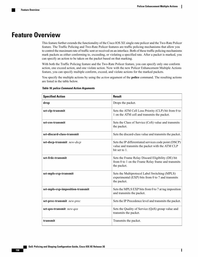
Feature OverviewThis feature further extends the functionality of the Cisco IOS XE single-rate policer and the Two-Rate Policerfeature. The Traffic Policing and Two-Rate Policer features are traffic policing mechanisms that allow youto control the maximum rate of traffic sent or received on an interface. Both of these traffic policingmechanismsmark packets as either conforming to, exceeding, or violating a specified rate. After a packet is marked, youcan specify an action to be taken on the packet based on that marking.
With both the Traffic Policing feature and the Two-Rate Policer feature, you can specify only one conformaction, one exceed action, and one violate action. Now with the new Policer Enhancement Multiple Actionsfeature, you can specify multiple conform, exceed, and violate actions for the marked packets.
You specify the multiple actions by using the action argument of the police command. The resulting actionsare listed in the table below.
Table 16: police Command Action Arguments
ResultSpecified Action
Drops the packet.drop
Sets the ATM Cell Loss Priority (CLP) bit from 0 to1 on the ATM cell and transmits the packet.
set-clp-transmit
Sets the Class of Service (CoS) value and transmitsthe packet.
set-cos-transmit
Sets the discard-class value and transmits the packet.set-discard-class-transmit
Sets the IP differentiated services code point (DSCP)value and transmits the packet with the ATM CLPbit set to 1.
set-dscp-transmit new-dscp
Sets the Frame Relay Discard Eligibility (DE) bitfrom 0 to 1 on the Frame Relay frame and transmitsthe packet.
set-frde-transmit
Sets the Multiprotocol Label Switching (MPLS)experimental (EXP) bits from 0 to 7 and transmitsthe packet.
set-mpls-exp-transmit
Sets theMPLS EXP bits from 0 to 7 at tag impositionand transmits the packet.
set-mpls-exp-imposition-transmit
Sets the IP Precedence level and transmits the packet.set-prec-transmit new-prec
Sets the Quality of Service (QoS) group value andtransmits the packet.
set-qos-transmit new-qos
Transmits the packet.transmit
QoS: Policing and Shaping Configuration Guide, Cisco IOS XE Release 3S150
Policer Enhancement Multiple ActionsFeature Overview
BenefitsBefore this feature, you could specify only one marking action for a packet, in addition to transmitting thepacket. This feature provides enhanced flexibility by allowing you to specify multiple marking actions for apacket, as required. For example, if you know the packet will be transmitted through both a TCP/IP and aFrame Relay environment, you can change the DSCP value of the exceeding or violating packet, and also setthe Frame Relay Discard Eligibility (DE) bit from 0 to 1 to indicate lower priority.
RestrictionsThe shape (percent) command, when used in "child" (nested) policy maps, is not supported on the Cisco7500, the Cisco 7200, or lower series routers. Therefore, the shape (percent) command cannot be configuredfor use in nested policy maps on these routers.
Related Features and Technologies• Modular Quality of Service (QoS) Command-Line Interface (CLI) (MQC)
• Class-Based Weighted Fair Queueing (CBWFQ)
• Class-Based Packet Marking
• Traffic Policing
• Two-Rate Policing
Related Documents• "Applying QoS Features Using the MQC" module
• "Configuring Weighted Fair Queueing" module
• "Marking Network Traffic" module
• "Policing and Shaping Overview" module
• "Traffic Policing" module
• "Two-Rate Policer" module
• "Policer Enhancements-Multiple Actions" module
• "Cisco Express Forwarding Overview" module
• Cisco IOS Quality of Service Solutions Command Reference
• Cisco IOS Switching Services Command Reference
• RFC 2697, A Single Rate Three Color Marker
• RFC 2698, A Two Rate Three Color Marker
QoS: Policing and Shaping Configuration Guide, Cisco IOS XE Release 3S 151
Policer Enhancement Multiple ActionsBenefits

Supported Standards MIBs and RFCsStandards
None
MIBs
• CISCO-CLASS-BASED-QOS-MIB
• CISCO-CLASS-BASED-QOS-CAPABILITY-MIB
To locate and download MIBs for selected platforms, Cisco IOS releases, and feature sets, use Cisco MIBLocator found at the following URL:
http://tools.cisco.com/ITDIT/MIBS/servlet/index
If Cisco MIB Locator does not support the MIB information that you need, you can also obtain a list ofsupported MIBs and download MIBs from the Cisco MIBs page at the following URL:
http://www.cisco.com/public/sw-center/netmgmt/cmtk/mibs.shtml
To access Cisco MIB Locator, you must have an account on Cisco.com. If you have forgotten or lost youraccount information, send a blank e-mail to [email protected]. An automatic check will verify thatyour e-mail address is registered with Cisco.com. If the check is successful, account details with a new randompassword will be e-mailed to you. Qualified users can establish an account on Cisco.com by following thedirections found at this URL:
http://www.cisco.com/register
RFCs
None
Prerequisites• On a Cisco 7500 series router, CEF or dCEF must be configured on the interface before you can use thePolicer Enhancement -- Multiple Actions feature.
• To configure the Policer Enhancement -- Multiple Actions feature, a traffic class and a service policymust be created, and the service policy must be attached to a specified interface.
QoS: Policing and Shaping Configuration Guide, Cisco IOS XE Release 3S152
Policer Enhancement Multiple ActionsSupported Standards MIBs and RFCs

Configuration Tasks
Configuring Multiple Policer Actions
SUMMARY STEPS
1. Router(config)# policy-map policy-map-name2. Router(config-pmap)# class class-default3. Router(config-pmap-c)# police {cir cir}[bc conform-burst]{pir pir} [be peak-burst] [conform-action
action [exceed-action action [violate-action action]]]
DETAILED STEPS
PurposeCommand or Action
Creates a policy map. Enters policy-map configuration mode.Router(config)# policy-map policy-map-nameStep 1
Specifies the default traffic class for a service policy. Enterspolicy-map class configuration mode.
Router(config-pmap)# class class-defaultStep 2
Configures traffic policing and specifies multiple actions appliedto packets marked as conforming to, exceeding, or violating a
Router(config-pmap-c)# police {cir cir}[bcconform-burst]{pir pir} [be peak-burst]
Step 3
specific rate. Use one line per action that you want to specify.Enters policy-map class police configuration mode.
[conform-action action [exceed-action action[violate-action action]]]
Verifying the Multiple Policer Actions ConfigurationPurposeCommand
Displays statistics and configurations of all input andoutput policies attached to an interface.Router#
show policy-map interface
Troubleshooting Tips• Check the interface type. Verify that your interface is not listed as a nonsupported interface.
• For input traffic policing on a Cisco 7500 series router, verify that Cisco Express Forwarding orDistributed Cisco Express Forwarding is configured on the interface on which traffic policing isconfigured.
QoS: Policing and Shaping Configuration Guide, Cisco IOS XE Release 3S 153
Policer Enhancement Multiple ActionsConfiguration Tasks
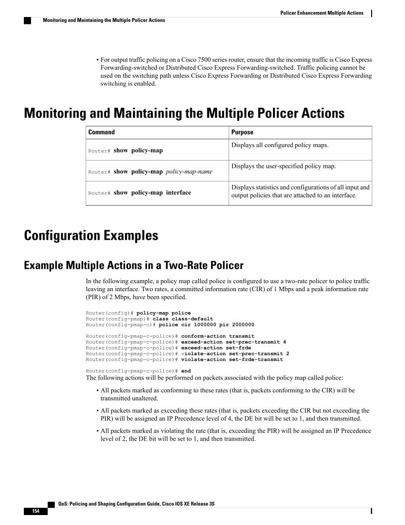
• For output traffic policing on a Cisco 7500 series router, ensure that the incoming traffic is Cisco ExpressForwarding-switched or Distributed Cisco Express Forwarding-switched. Traffic policing cannot beused on the switching path unless Cisco Express Forwarding or Distributed Cisco Express Forwardingswitching is enabled.
Monitoring and Maintaining the Multiple Policer ActionsPurposeCommand
Displays all configured policy maps.Router# show policy-map
Displays the user-specified policy map.Router# show policy-map policy-map-name
Displays statistics and configurations of all input andoutput policies that are attached to an interface.Router# show policy-map interface
Configuration Examples
Example Multiple Actions in a Two-Rate PolicerIn the following example, a policy map called police is configured to use a two-rate policer to police trafficleaving an interface. Two rates, a committed information rate (CIR) of 1 Mbps and a peak information rate(PIR) of 2 Mbps, have been specified.
Router(config)# policy-map policeRouter(config-pmap)# class class-defaultRouter(config-pmap-c)# police cir 1000000 pir 2000000
Router(config-pmap-c-police)# conform-action transmitRouter(config-pmap-c-police)# exceed-action set-prec-transmit 4Router(config-pmap-c-police)# exceed-action set-frdeRouter(config-pmap-c-police)# violate-action set-prec-transmit 2Router(config-pmap-c-police)# violate-action set-frde-transmit
Router(config-pmap-c-police)# endThe following actions will be performed on packets associated with the policy map called police:
• All packets marked as conforming to these rates (that is, packets conforming to the CIR) will betransmitted unaltered.
• All packets marked as exceeding these rates (that is, packets exceeding the CIR but not exceeding thePIR) will be assigned an IP Precedence level of 4, the DE bit will be set to 1, and then transmitted.
• All packets marked as violating the rate (that is, exceeding the PIR) will be assigned an IP Precedencelevel of 2, the DE bit will be set to 1, and then transmitted.
QoS: Policing and Shaping Configuration Guide, Cisco IOS XE Release 3S154
Policer Enhancement Multiple ActionsMonitoring and Maintaining the Multiple Policer Actions

Example Verifying the Multiple Policer ActionsThe following sample output of the show policy-mapcommand displays the configuration for a service policycalled police. In this service policy, multiple actions for packets marked as exceeding the specified CIR ratehave been configured. For those packets, the IP Precedence level is set to 4, the DE bit is set to 1, and thepacket is transmitted. Multiple actions for packets marked as violating the specified PIR rate have also beenconfigured. For those packets, the IP Precedence level is set to 2, the DE bit is set to 1, and the packet istransmitted.
Router# show policy-map policePolicy Map policeClass class-defaultpolice cir 1000000 bc 31250 pir 2000000 be 31250conform-action transmitexceed-action set-prec-transmit 4exceed-action set-frde-transmitviolate-action set-prec-transmit 2violate-action set-frde-transmit
Feature Information for Policer Enhancement Multiple ActionsThe following table provides release information about the feature or features described in this module. Thistable lists only the software release that introduced support for a given feature in a given software releasetrain. Unless noted otherwise, subsequent releases of that software release train also support that feature.
Use Cisco Feature Navigator to find information about platform support and Cisco software image support.To access Cisco Feature Navigator, go to www.cisco.com/go/cfn. An account on Cisco.com is not required.
Table 17: Feature Information for QoS for dVTI
Feature InformationReleasesFeature Name
Policer Enhancement MultipleActions specifiesmultiple conform,exceed, and violate actions formarked packets.
Cisco IOS XE Release 2.1Policer Enhancement MultipleActions
QoS: Policing and Shaping Configuration Guide, Cisco IOS XE Release 3S 155
Policer Enhancement Multiple ActionsExample Verifying the Multiple Policer Actions

QoS: Policing and Shaping Configuration Guide, Cisco IOS XE Release 3S156
Policer Enhancement Multiple ActionsFeature Information for Policer Enhancement Multiple Actions

C H A P T E R 14Control Plane Policing
The Control Plane Policing feature allows you to configure a quality of service (QoS) filter that managesthe traffic flow of control plane packets to protect the control plane of Cisco IOS XE routers and switchesagainst reconnaissance and denial-of-service (DoS) attacks. In this way, the control plane (CP) can helpmaintain packet forwarding and protocol states despite an attack or heavy traffic load on the router or switch.
• Finding Feature Information, page 157
• Restrictions for Control Plane Policing, page 158
• Information About Control Plane Policing, page 159
• How to Use Control Plane Policing, page 161
• Configuration Examples for Control Plane Policing, page 166
• Information About Per-Interface QoS for PPPoE Punt Traffics on Cisco ASR 1000 Series Routers,page 169
• Enabling QoS Policing and Matching for PPPoE Traffic on the Input Interface, page 169
• Disabling QoS Policing and Matching for PPPoE Traffic on the Input Interface, page 170
• Example: Configuring PPPoE and PPPoE Discovery Packets on the Input Interface and Control Plane,page 171
• Additional References for Control Plane Policing, page 171
• Feature Information for Control Plane Policing, page 172
Finding Feature InformationYour software release may not support all the features documented in this module. For the latest caveats andfeature information, see Bug Search Tool and the release notes for your platform and software release. Tofind information about the features documented in this module, and to see a list of the releases in which eachfeature is supported, see the feature information table at the end of this module.
Use Cisco Feature Navigator to find information about platform support and Cisco software image support.To access Cisco Feature Navigator, go to www.cisco.com/go/cfn. An account on Cisco.com is not required.
QoS: Policing and Shaping Configuration Guide, Cisco IOS XE Release 3S 157
Restrictions for Control Plane PolicingOutput Rate-Limiting Support
Output rate-limiting is performed in silent (packet discard) mode. Silent mode enables a router to silentlydiscard packets using policy maps applied to output control plane traffic with the service-policy outputcommand. For more information, see the “Output Rate-Limiting and Silent Mode Operation” section.
MQC Restrictions
The Control Plane Policing feature requires the Modular QoS CLI (MQC) to configure packet classification,packet marking, and traffic policing. All restrictions that apply when you use the MQC to configure trafficpolicing also apply when you configure control plane policing. Only two MQC commands are supported inpolicy maps—police and set.
Match Criteria Support and Restrictions
The following classification (match) criteria are supported:
• Standard and extended IP access control lists (ACLs).
• In class-map configuration mode, match criteria specified by the following commands:
• match dscp
• match ip dscp
• match ip precedence
• match precedence
• match protocol arp
• match protocol ipv6
• match protocol pppoe
Thematch protocol pppoe command matches all PPPoE data packets that are sent to the control plane.Note
• match protocol pppoe-discovery
Thematch protocol pppoe-discovery command matches all PPPoE control packets that are sent to thecontrol plane.
Note
• match qos-group
QoS: Policing and Shaping Configuration Guide, Cisco IOS XE Release 3S158
Control Plane PolicingRestrictions for Control Plane Policing

Thematch input-interface command is not supported.Note
Features that require Network-Based Application Recognition (NBAR) classification may not work wellat the control plane level.
Note
Information About Control Plane Policing
Benefits of Control Plane PolicingConfiguring the Control Plane Policing feature on your Cisco router or switch provides the following benefits:
• Protection against DoS attacks at infrastructure routers and switches
• QoS control for packets that are destined to the control plane of Cisco routers or switches
• Ease of configuration for control plane policies
• Better platform reliability and availability
Control Plane Terms to UnderstandOn the Cisco ASR 1000 Series Router, the following terms are used for the Control Plane Policing feature:
• Control plane—A collection of processes that run at the process level on the Route Processor (RP).These processes collectively provide high-level control for most Cisco IOS XE functions. The trafficsent to or sent by the control plane is called control traffic.
• Forwarding plane—A device that is responsible for high-speed forwarding of IP packets. Its logic iskept simple so that it can be implemented by hardware to do fast packet-forwarding. It punts packetsthat require complex processing (for example, packets with IP options) to the RP for the control planeto process them.
Control Plane Policing OverviewTo protect the control plane on a router from DoS attacks and to provide fine-control over the traffic to orfrom the control plane, the Control Plane Policing feature treats the control plane as a separate entity with itsown interface for ingress (input) and egress (output) traffic. This interface is called the punt/inject interface,and it is similar to a physical interface on the router. Along this interface, packets are punted from the forwardingplane to the RP (in the input direction) and injected from the RP to the forwarding plane (in the output direction).A set of quality of service (QoS) rules can be applied on this interface in order to achieve CoPP.
These QoS rules are applied only after the packet has been determined to have the control plane as its destinationor when a packet exits from the control plane. You can configure a service policy (QoS policy map) to preventunwanted packets from progressing after a specified rate limit has been reached; for example, a system
QoS: Policing and Shaping Configuration Guide, Cisco IOS XE Release 3S 159
Control Plane PolicingInformation About Control Plane Policing

administrator can limit all TCP/SYN packets that are destined for the control plane to a maximum rate of 1megabit per second.
Figure 4: Abstract Illustration of a Cisco ASR 1000 Series Router with Dual RPs and Dual Forwarding Panes
The figure above provides an abstract illustration of a Cisco ASR 1000 Series Router with dual RPs and dualforwarding planes. Only one RP and one forwarding plane are active at any time. The other RP and forwardingplane are in stand-by mode and do not receive traffic from the carrier card (CC). Packets destined to the controlplane come in through the carrier card and then go through the active forwarding plane before being puntedto the active RP. When an input QoS policy map is configured on the control plane, the active forwardingplane performs the QoS action (for example, a transmit, drop, or set action) before punting packets to theactive RP in order to achieve the best protection of the control plane in the active RP.
On the other hand, packets exiting the control plane are injected to the active forwarding plane, and then goout through the carrier card. When an output QoS policy map is configured on the control plane, the activeforwarding plane performs the QoS action after receiving the injected packets from the RP. This process savesthe valuable CPU resource in the RP.
As shown in “Control Plane Policing Overview” section, the management interface is directly connectedto the RP, so all traffic through the management interface to or from the control-plane is not subject tothe CoPP function performed by the forwarding plane.
Note
In high-availability (HA) mode, when an RP switchover happens, the active forwarding plane forwards trafficto the new active RP along the new punt/inject interface. The active forwarding plane continues to performthe CoPP function before punting traffic to the new active RP. When a forwarding plane switchover happens,the new active forwarding plane receives traffic from the carrier card and performs the CoPP function beforepunting traffic to the active RP.
QoS: Policing and Shaping Configuration Guide, Cisco IOS XE Release 3S160
Control Plane PolicingControl Plane Policing Overview
The Cisco ASR 1000 Series Router handles some traditional control traffic in the forwarding plane directlyto reduce the load on the control plane. One example is the IP Internet Control Message Protocol (ICMP)echo-request packet sent to this router. When a Cisco ASR1000 Series Router receives such packets, thepackets are handled directly in the forwarding plane without being punted to the RP. In order to be consistentwith other Cisco routers and to provide the same capability to control such packets using CoPP, the CiscoASR 1000 series router extends the CoPP function on such packets, even though the packets are not puntedto the RP. Customers can still use the CoPP function to rate-limit or to mark such packets.
Note
Output Rate-Limiting and Silent Mode OperationA router is automatically enabled to silently discard packets when you configure output policing on controlplane traffic using the service-policy output policy-map-name command.
Rate-limiting (policing) of output traffic from the control plane is performed in silent mode. In silent mode,a router that is running Cisco IOS XE software operates without sending any system messages. If a packetthat is exiting the control plane is discarded for output policing, you do not receive an error message.
How to Use Control Plane Policing
Defining Control Plane ServicesPerform this task to define control plane services, such as packet rate control and silent packet discard for theactive RP.
Before You Begin
Before you enter control-plane configuration mode to attach an existing QoS policy to the control plane, youmust first create the policy using MQC to define a class map and policy map for control plane traffic.
Note • Platform-specific restrictions, if any, are checked when the service policy is applied to the controlplane interface.
• Output policing does not provide any performance benefits. It simply controls the information thatis leaving the device.
SUMMARY STEPS
1. enable2. configure terminal3. control-plane4. service-policy {input | output policy-map-name}5. end
QoS: Policing and Shaping Configuration Guide, Cisco IOS XE Release 3S 161
Control Plane PolicingOutput Rate-Limiting and Silent Mode Operation
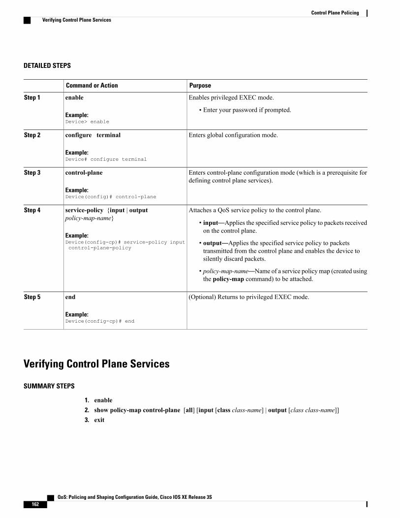
DETAILED STEPS
PurposeCommand or Action
Enables privileged EXEC mode.enableStep 1
Example:Device> enable
• Enter your password if prompted.
Enters global configuration mode.configure terminal
Example:Device# configure terminal
Step 2
Enters control-plane configuration mode (which is a prerequisite fordefining control plane services).
control-plane
Example:Device(config)# control-plane
Step 3
Attaches a QoS service policy to the control plane.service-policy {input | outputpolicy-map-name}
Step 4
• input—Applies the specified service policy to packets receivedon the control plane.
Example:Device(config-cp)# service-policy inputcontrol-plane-policy
• output—Applies the specified service policy to packetstransmitted from the control plane and enables the device tosilently discard packets.
• policy-map-name—Name of a service policymap (created usingthe policy-map command) to be attached.
(Optional) Returns to privileged EXEC mode.end
Example:Device(config-cp)# end
Step 5
Verifying Control Plane Services
SUMMARY STEPS
1. enable2. show policy-map control-plane [all] [input [class class-name] | output [class class-name]]3. exit
QoS: Policing and Shaping Configuration Guide, Cisco IOS XE Release 3S162
Control Plane PolicingVerifying Control Plane Services

DETAILED STEPS
PurposeCommand or Action
Enables privileged EXEC mode.enableStep 1
Example:Device> enable
• Enter your password if prompted.
Displays information about the control plane.show policy-map control-plane [all] [input[class class-name] | output [classclass-name]]
Step 2
• all—(Optional) Displays service policy information about all QoSpolicies used on the CP.
Example:Device# show policy-map control-planeall
• input—(Optional) Displays statistics for the attached input policy.
• output—(Optional) Displays statistics for the attached outputpolicy.
• class class-name—(Optional) Specifies the name of the trafficclass whose configuration and statistics are displayed.
(Optional) Exits privileged EXEC mode.exit
Example:Device# exit
Step 3
Examples
The following example shows that the policy map TEST is associated with the control plane. This policy mappolices traffic that matches the class map TEST, while allowing all other traffic (that matches the class map"class-default") to go through as is.
Device# show policy-map control-plane
Control PlaneService-policy input:TESTClass-map:TEST (match-all)
20 packets, 11280 bytes5 minute offered rate 0 bps, drop rate 0 bpsMatch:access-group 101police:8000 bps, 1500 limit, 1500 extended limitconformed 15 packets, 6210 bytes; action:transmitexceeded 5 packets, 5070 bytes; action:dropviolated 0 packets, 0 bytes; action:dropconformed 0 bps, exceed 0 bps, violate 0 bps
Class-map:class-default (match-any)105325 packets, 11415151 bytes5 minute offered rate 0 bps, drop rate 0 bpsMatch:any
QoS: Policing and Shaping Configuration Guide, Cisco IOS XE Release 3S 163
Control Plane PolicingVerifying Control Plane Services
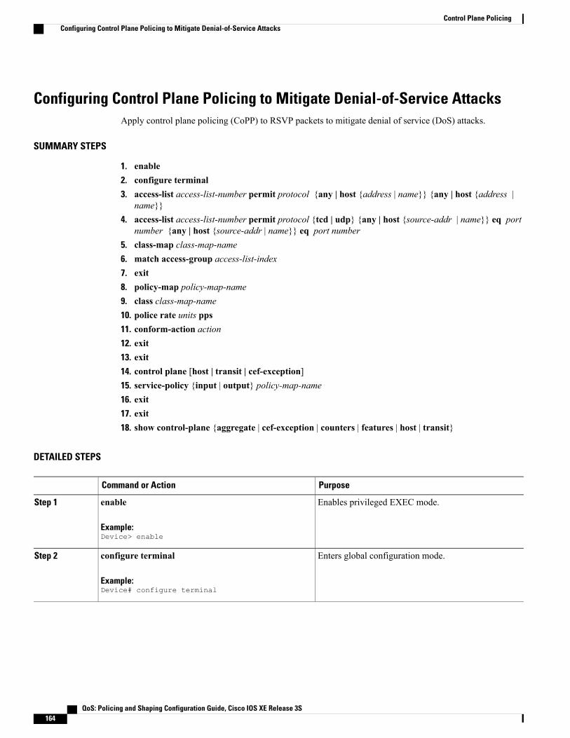
Configuring Control Plane Policing to Mitigate Denial-of-Service AttacksApply control plane policing (CoPP) to RSVP packets to mitigate denial of service (DoS) attacks.
SUMMARY STEPS
1. enable2. configure terminal3. access-list access-list-number permit protocol {any | host {address | name}} {any | host {address |
name}}4. access-list access-list-number permit protocol {tcd | udp} {any | host {source-addr | name}} eq port
number {any | host {source-addr | name}} eq port number5. class-map class-map-name6. match access-group access-list-index7. exit8. policy-map policy-map-name9. class class-map-name10. police rate units pps11. conform-action action12. exit13. exit14. control plane [host | transit | cef-exception]15. service-policy {input | output} policy-map-name16. exit17. exit18. show control-plane {aggregate | cef-exception | counters | features | host | transit}
DETAILED STEPS
PurposeCommand or Action
Enables privileged EXEC mode.enable
Example:Device> enable
Step 1
Enters global configuration mode.configure terminal
Example:Device# configure terminal
Step 2
QoS: Policing and Shaping Configuration Guide, Cisco IOS XE Release 3S164
Control Plane PolicingConfiguring Control Plane Policing to Mitigate Denial-of-Service Attacks
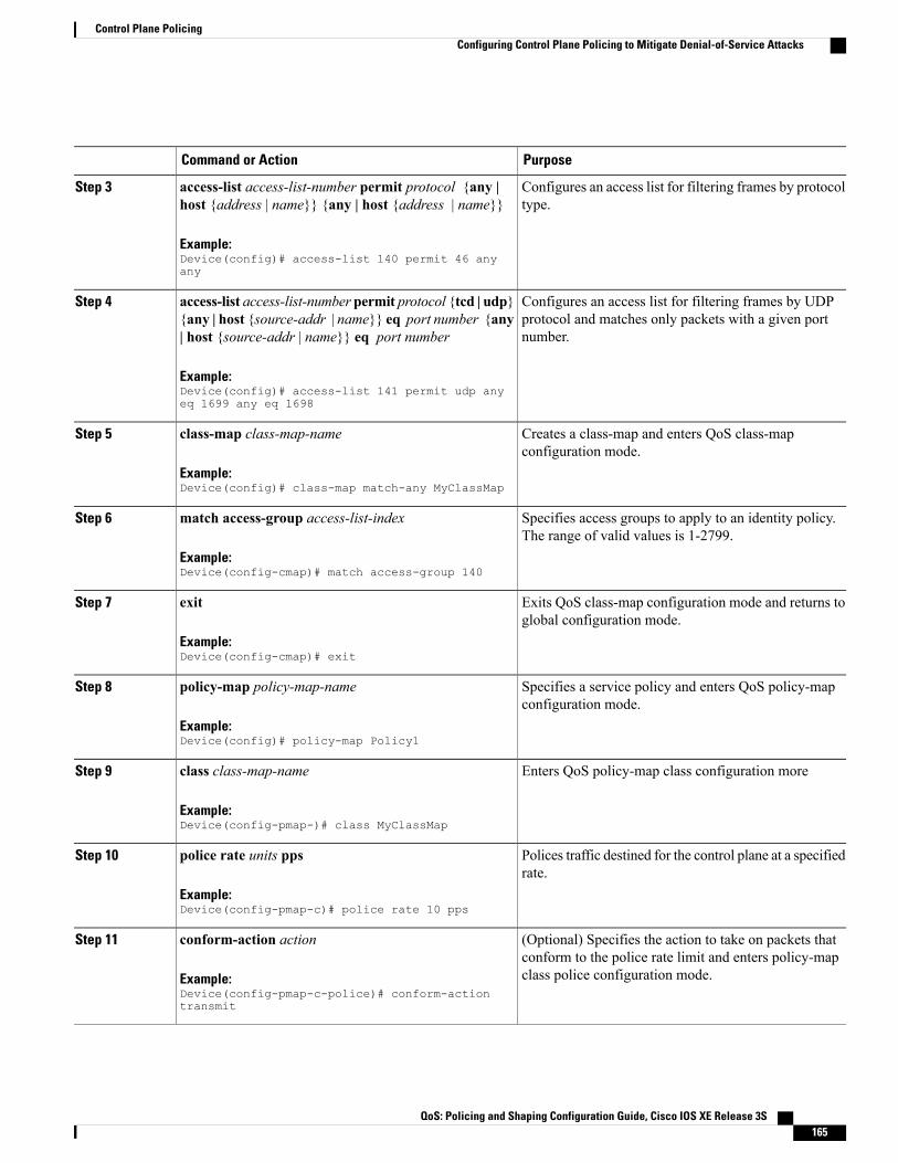
PurposeCommand or Action
Configures an access list for filtering frames by protocoltype.
access-list access-list-number permit protocol {any |host {address | name}} {any | host {address | name}}
Example:Device(config)# access-list 140 permit 46 anyany
Step 3
Configures an access list for filtering frames by UDPprotocol and matches only packets with a given portnumber.
access-list access-list-number permit protocol {tcd | udp}{any | host {source-addr | name}} eq port number {any| host {source-addr | name}} eq port number
Example:Device(config)# access-list 141 permit udp anyeq 1699 any eq 1698
Step 4
Creates a class-map and enters QoS class-mapconfiguration mode.
class-map class-map-name
Example:Device(config)# class-map match-any MyClassMap
Step 5
Specifies access groups to apply to an identity policy.The range of valid values is 1-2799.
match access-group access-list-index
Example:Device(config-cmap)# match access-group 140
Step 6
Exits QoS class-map configuration mode and returns toglobal configuration mode.
exit
Example:Device(config-cmap)# exit
Step 7
Specifies a service policy and enters QoS policy-mapconfiguration mode.
policy-map policy-map-name
Example:Device(config)# policy-map Policy1
Step 8
Enters QoS policy-map class configuration moreclass class-map-name
Example:Device(config-pmap-)# class MyClassMap
Step 9
Polices traffic destined for the control plane at a specifiedrate.
police rate units pps
Example:Device(config-pmap-c)# police rate 10 pps
Step 10
(Optional) Specifies the action to take on packets thatconform to the police rate limit and enters policy-mapclass police configuration mode.
conform-action action
Example:Device(config-pmap-c-police)# conform-actiontransmit
Step 11
QoS: Policing and Shaping Configuration Guide, Cisco IOS XE Release 3S 165
Control Plane PolicingConfiguring Control Plane Policing to Mitigate Denial-of-Service Attacks
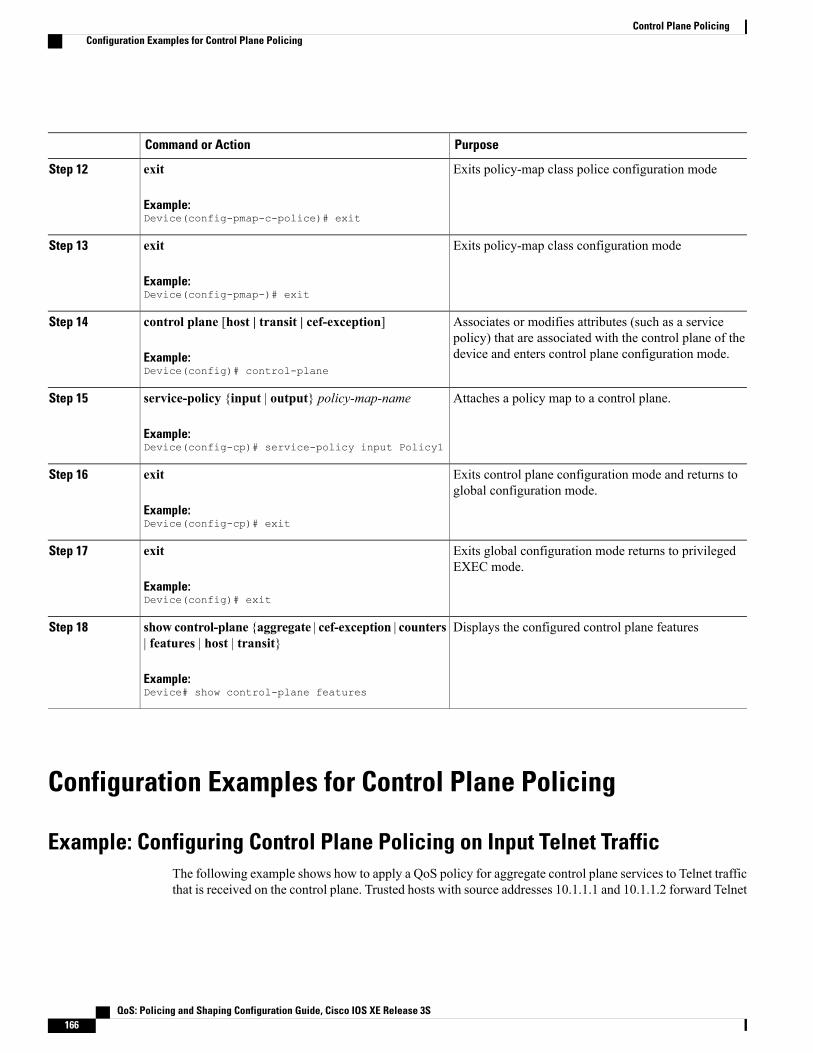
PurposeCommand or Action
Exits policy-map class police configuration modeexit
Example:Device(config-pmap-c-police)# exit
Step 12
Exits policy-map class configuration modeexit
Example:Device(config-pmap-)# exit
Step 13
Associates or modifies attributes (such as a servicepolicy) that are associated with the control plane of thedevice and enters control plane configuration mode.
control plane [host | transit | cef-exception]
Example:Device(config)# control-plane
Step 14
Attaches a policy map to a control plane.service-policy {input | output} policy-map-name
Example:Device(config-cp)# service-policy input Policy1
Step 15
Exits control plane configuration mode and returns toglobal configuration mode.
exit
Example:Device(config-cp)# exit
Step 16
Exits global configuration mode returns to privilegedEXEC mode.
exit
Example:Device(config)# exit
Step 17
Displays the configured control plane featuresshow control-plane {aggregate | cef-exception | counters| features | host | transit}
Step 18
Example:Device# show control-plane features
Configuration Examples for Control Plane Policing
Example: Configuring Control Plane Policing on Input Telnet TrafficThe following example shows how to apply a QoS policy for aggregate control plane services to Telnet trafficthat is received on the control plane. Trusted hosts with source addresses 10.1.1.1 and 10.1.1.2 forward Telnet
QoS: Policing and Shaping Configuration Guide, Cisco IOS XE Release 3S166
Control Plane PolicingConfiguration Examples for Control Plane Policing

packets to the control plane without constraint while allowing all remaining Telnet packets to be policed atthe specified rate.
! Allow 10.1.1.1 trusted host traffic.Device(config)# access-list 140 deny tcp host 10.1.1.1 any eq telnet
! Allow 10.1.1.2 trusted host traffic.Device(config)# access-list 140 deny tcp host 10.1.1.2 any eq telnet
! Rate-limit all other Telnet traffic.Device(config)# access-list 140 permit tcp any any eq telnet! Define class-map "telnet-class."Device(config)# class-map telnet-class
Device(config-cmap)# match access-group 140Device(config-cmap)# exitDevice(config)# policy-map control-plane-inDevice(config-pmap)# class telnet-classDevice(config-pmap-c)# police 80000 conform transmit exceed dropDevice(config-pmap-c)# exitDevice(config-pmap)# exit! Define aggregate control plane service for the active route processor.Device(config)# control-planeDevice(config-cp)# service-policy input control-plane-inDevice(config-cp)# end
Example: Configuring Control Plane Policing on Output ICMP TrafficThe following example shows how to apply a QoS policy for aggregate control plane services to Telnet traffictransmitted from the control plane. Trusted networks with source addresses 10.0.0.0 and 10.0.0.1 receiveInternet Control Management Protocol (ICMP) port-unreachable responses without constraint while allowingall remaining ICMP port-unreachable responses to be dropped.
! Allow 10.0.0.0 trusted network traffic.Device(config)# access-list 141 deny icmp 10.0.0.0 0.0.0.255 any port-unreachable
! Allow10.0.0.1trusted network traffic.Device(config)# access-list 141 deny icmp 10.0.0.1 0.0.0.255 any port-unreachable
! Rate-limit all other ICMP traffic.Device(config)# access-list 141 permit icmp any any port-unreachableDevice(config)# class-map icmp-class
Device(config-cmap)# match access-group 141Device(config-cmap)# exitDevice(config)# policy-map control-plane-out! Drop all traffic that matches the class "icmp-class."Device(config-pmap)# class icmp-classDevice(config-pmap-c)# dropDevice(config-pmap-c)# exitDevice(config-pmap)# exitDevice(config)# control-plane! Define aggregate control plane service for the active route processor.Device(config-cp)# service-policy output control-plane-outDevice(config-cp)# end
QoS: Policing and Shaping Configuration Guide, Cisco IOS XE Release 3S 167
Control Plane PolicingExample: Configuring Control Plane Policing on Output ICMP Traffic

Example: Marking Output Control Plane PacketsThe following example shows how to apply a QoS policy on the control plane to mark all egress IPv6echo-request packets with IPv6 precedence 6.
! Match all IPv6 Echo RequestsDevice(config)# ipv6 access-list coppacl-ipv6-icmp-requestDevice(config-ipv6-acl)# permit icmp any any echo-requestDevice(config-ipv6-acl)# exitDevice(config)# class-map match-all coppclass-ipv6-icmp-requestDevice(config-cmap)# match access-group name coppacl-ipv6-icmp-requestDevice(config-cmap)# exit! Set all egress IPv6 Echo Requests with precedence 6Device(config)# policy-map copp-policyDevice(config-pmap)# class coppclass-ipv6-icmp-requestDevice(config-pmap-c)# set precedence 6Device(config-pmap-c)# exitDevice(config-pmap)# exit! Define control plane service for the active route processor.Device(config)# control-planeDevice(config-cp)# service-policy output copp-policyDevice(config-cp)# end
Example: Configuring Control Plane Policing to Mitigate Denial-of-ServiceAttacks
The following example shows how to configure control plane policing (CoPP) to police RSVP packets at aspecified rate and displays configured CoPP features.Device> enableDevice# configure terminalEnter configuration commands, one per line. End with CNTL/Z.Device(config)# access-list 140 permit 46 any anyDevice(config)# access-list 141 permit adp any eq 1699 any eq 1698Device(config)# class-map match-any MyClassMapDevice(config-cmap)# match access-group 140Device(config-cmap)# match access-group 141Device(config-cmap)# exitDevice(config)# policy-map Policy1Device(config-pmap)# class MyClassMapDevice(config-pmap-c)# police rate 10 ppsDevice(config-pmap-c-police)# conform-action transmitDevice(config-pmap-c-police)# exceed-action dropDevice(config-pmap-c-police)# exitDevice(config-pmap-c)# exitDevice(config-pmap)# exitDevice(config)# control-planeDevice(config-cp)# service-policy input Policy1Device(config-cp)#*Sep 14 08:07:39.898: %CP-5-FEATURE: Control-plane Policing feature enabled on Control planeaggregate pathDevice(config-cp)#Device(config-c p)# exitDevice(config)# exitDevice#*Sep 14 08:09:04.154: %SYS-5-CONFIG_I: Configured from console by consoleDevice# show control-plane featuresTotal 1 features configured
Control plane aggregate path features :
--------------------------------------------------------Control-plane Policing activated Sep 14 2012 08:0
QoS: Policing and Shaping Configuration Guide, Cisco IOS XE Release 3S168
Control Plane PolicingExample: Marking Output Control Plane Packets

--------------------------------------------------------
Information About Per-Interface QoS for PPPoE Punt Trafficson Cisco ASR 1000 Series Routers
Overview of the Per-Interface QoS for PPPoE Punt Traffic FeaturePrior to Cisco IOS XE Release 3.12, PPP over Ethernet (PPPoE) punt traffic policing was performed only onthe control plane. However, this policing could not be applied to the input interface. Effective from Cisco IOSXE 3.12S, the Per-Interface QoS for PPPoE Punt Traffic feature applies QoS policing and matching for PPPoEtraffic on both the interface and the control plane. This feature polices the PPPoE discovery and PPPoE LinkControl Protocol (LCP) packets on the interface of the Point-to-Point Termination and Aggregation (PTA)and the Local Access Concentrator (LAC). Policing the PPPoE discovery and PPPoE LCP packets on theinterface has an important role in reducing the load on the control plane. Punt traffic on input interface willgo to the control plane.
For QoS policy maps, applying the policer on both the interface and the control plane improves networkavailability. It also provides the customer with the flexibility required for implementing security and policing.
Enabling QoS Policing and Matching for PPPoE Traffic on theInput InterfaceSUMMARY STEPS
1. enable2. configure terminal3. platform qos punt-path-matching4. end
DETAILED STEPS
PurposeCommand or Action
Enables privileged EXEC mode.enableStep 1
Example:Device> enable
Enters global configuration mode.configure terminalStep 2
Example:Device# configure terminal
QoS: Policing and Shaping Configuration Guide, Cisco IOS XE Release 3S 169
Control Plane PolicingInformation About Per-Interface QoS for PPPoE Punt Traffics on Cisco ASR 1000 Series Routers
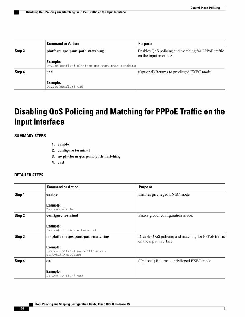
PurposeCommand or Action
Enables QoS policing and matching for PPPoE trafficon the input interface.
platform qos punt-path-matching
Example:Device(config)# platform qos punt-path-matching
Step 3
(Optional) Returns to privileged EXEC mode.endStep 4
Example:Device(config)# end
Disabling QoS Policing and Matching for PPPoE Traffic on theInput InterfaceSUMMARY STEPS
1. enable2. configure terminal3. no platform qos punt-path-matching4. end
DETAILED STEPS
PurposeCommand or Action
Enables privileged EXEC mode.enableStep 1
Example:Device> enable
Enters global configuration mode.configure terminalStep 2
Example:Device# configure terminal
Disables QoS policing and matching for PPPoE trafficon the input interface.
no platform qos punt-path-matching
Example:Device(config)# no platform qospunt-path-matching
Step 3
(Optional) Returns to privileged EXEC mode.endStep 4
Example:Device(config)# end
QoS: Policing and Shaping Configuration Guide, Cisco IOS XE Release 3S170
Control Plane PolicingDisabling QoS Policing and Matching for PPPoE Traffic on the Input Interface

Example: Configuring PPPoE and PPPoE Discovery Packets onthe Input Interface and Control Plane
The following example shows how to configure PPPoE and PPPoE discovery packets on the input interfaceand control plane:
Device#configure terminalDevice(config)#class-map pppoedDevice(config-cmap)#match protocol pppoe-discoveryDevice(config-cmap)#class-map pppoeDevice(config-cmap)#match protocol pppoeDevice(config-cmap)#policy-map pppoe-inputDevice(config-pmap)#class pppoed
Device(config-pmap-c)#police 10000Device(config-pmap-c-police)#class pppoeDevice(config-pmap-c)#police 10000Device(config-pmap-c-police)#int g0/0/0.100Device(config-subif)#service-p input pppoe-input
Device(config-subif)#end
Device#show platform hardware qfp active feature qos config global
Punt-Path-Matching are: enabled
Additional References for Control Plane PolicingRelated Documents
Document TitleRelated Topic
Cisco IOS Quality of Service Solutions CommandReference
QoS commands: complete command syntax,command modes, command history, defaults, usageguidelines, and examples
“Quality of Service Overview” moduleQoS features overview
“Applying QoS Features Using the MQC” moduleMQC
“Security Overview” moduleSecurity features overview
QoS: Policing and Shaping Configuration Guide, Cisco IOS XE Release 3S 171
Control Plane PolicingExample: Configuring PPPoE and PPPoE Discovery Packets on the Input Interface and Control Plane

MIBs
MIBs LinkMIB
To locate and downloadMIBs for selected platforms,Cisco IOSXE Software releases, and feature sets, useCisco MIB Locator found at the following URL:
http://www.cisco.com/go/mibs
CISCO-CLASS-BASED-QOS-MIB
Technical Assistance
LinkDescription
http://www.cisco.com/cisco/web/support/index.htmlThe Cisco Support and Documentation websiteprovides online resources to download documentation,software, and tools. Use these resources to install andconfigure the software and to troubleshoot and resolvetechnical issues with Cisco products and technologies.Access to most tools on the Cisco Support andDocumentation website requires a Cisco.com user IDand password.
Feature Information for Control Plane PolicingThe following table provides release information about the feature or features described in this module. Thistable lists only the software release that introduced support for a given feature in a given software releasetrain. Unless noted otherwise, subsequent releases of that software release train also support that feature.
Use Cisco Feature Navigator to find information about platform support and Cisco software image support.To access Cisco Feature Navigator, go to www.cisco.com/go/cfn. An account on Cisco.com is not required.
QoS: Policing and Shaping Configuration Guide, Cisco IOS XE Release 3S172
Control Plane PolicingFeature Information for Control Plane Policing

Table 18: Feature Information for Control Plane Policing
Feature InformationReleasesFeature Name
The Control Plane Policing featureallows users to configure a qualityof service (QoS) filter that managesthe traffic flow of control planepackets to protect the control planeof Cisco IOS routers and switchesagainst reconnaissance anddenial-of-service (DoS) attacks.
For Cisco IOSXERelease 2.1, thisfeature was implemented on CiscoASR 1000 Series Routers.
For Cisco IOSXERelease 2.2, thisfeature was modified to includesupport for packet marking, outputrate-limiting, and additional matchcriteria.
The following commands wereintroduced or modified:matchprotocol pppoe, match protocolpppoe-discovery.
Cisco IOS XE Release 2.1
Cisco IOS XE Release 2.2
Control Plane Policing
The Per-Interface QoS for PPPoEPunt Traffic on Cisco ASR 1000Series Routers feature applies QoSpolicing and matching for PPPoEtraffic on both the interface and thecontrol plane.
The following command wasintroduced:
platformqos punt-path-matching
Cisco IOS XE Release 3.12Per-Interface QoS for PPPoE PuntTraffic on Cisco ASR 1000 SeriesRouters
QoS: Policing and Shaping Configuration Guide, Cisco IOS XE Release 3S 173
Control Plane PolicingFeature Information for Control Plane Policing

QoS: Policing and Shaping Configuration Guide, Cisco IOS XE Release 3S174
Control Plane PolicingFeature Information for Control Plane Policing
C H A P T E R 15Management Plane Protection
First Published: February 27, 2006
Last Updated: February 27, 2006
The Management Plane Protection (MPP) feature in Cisco IOS software provides the capability to restrictthe interfaces on which network management packets are allowed to enter a device. The MPP feature allowsa network operator to designate one or more router interfaces as management interfaces. Device managementtraffic is permitted to enter a device only through these management interfaces. After MPP is enabled, nointerfaces except designated management interfaces will accept network management traffic destined to thedevice.
Restricting management packets to designated interfaces provides greater control over management of adevice, providing more security for that device. Other benefits include improved performance for data packetson nonmanagement interfaces, support for network scalability, need for fewer access control lists (ACLs)to restrict access to a device, and management packet floods on switching and routing interfaces are preventedfrom reaching the CPU.
Finding Feature Information in This Module
Your Cisco IOS software release may not support all of the features documented in this module. To reachlinks to specific feature documentation in this module and to see a list of the releases in which each featureis supported, use the Feature Information for Management Plane Protection, on page 182.
Finding Support Information for Platforms and Cisco IOS Software Images
Use Cisco Feature Navigator to find information about platform support and Cisco IOS software imagesupport. Access Cisco Feature Navigator at http://www.cisco.com/go/fn . You must have an account onCisco.com. If you do not have an account or have forgotten your username or password, click Cancel at thelogin dialog box and follow the instructions that appear.
• Finding Feature Information, page 176
• Prerequisites for Management Plane Protection, page 176
• Restrictions for Management Plane Protection, page 176
• Information About Management Plane Protection, page 176
• How to Configure a Device for Management Plane Protection, page 178
• Configuration Examples for Management Plane Protection, page 181
QoS: Policing and Shaping Configuration Guide, Cisco IOS XE Release 3S 175
• Additional References for Management Plane Protection, page 181
• Feature Information for Management Plane Protection, page 182
Finding Feature InformationYour software release may not support all the features documented in this module. For the latest caveats andfeature information, see Bug Search Tool and the release notes for your platform and software release. Tofind information about the features documented in this module, and to see a list of the releases in which eachfeature is supported, see the feature information table.
Use Cisco Feature Navigator to find information about platform support and Cisco software image support.To access Cisco Feature Navigator, go to www.cisco.com/go/cfn. An account on Cisco.com is not required.
Prerequisites for Management Plane Protection• IP Cisco Express Forwarding must be enabled before a management interface can be configured.
Restrictions for Management Plane Protection• Out-of-band management interfaces (also called dedicated management interfaces) are not supported.An out-of-bandmanagement interface is a dedicated Cisco IOS physical or logical interface that processesmanagement traffic only.
• Loopback and virtual interfaces not associated to physical interfaces are not supported.
• Fallback and standby management interfaces are not supported.
• Hardware-switched and distributed platforms are not supported.
• Secure Copy (SCP) is supported under the Secure Shell (SSH) Protocol and not directly configurablein the command-line interface (CLI).
• Uninformedmanagement stations lose access to the router through nondesignatedmanagement interfaceswhen the Management Plane Protection feature is enabled.
• This feature supports only IPv4 traffic. IPv6 traffic is neither blocked nor denied.
Information About Management Plane ProtectionBefore you enable the Management Plane Protection feature, you should understand the following concepts:
In-Band Management InterfaceAn in-band management interface is a Cisco IOS physical or logical interface that processes management aswell as data-forwarding packets. Loopback interfaces commonly are used as the primary port for networkmanagement packets. External applications communicating with a networking device direct network
QoS: Policing and Shaping Configuration Guide, Cisco IOS XE Release 3S176
Management Plane ProtectionFinding Feature Information
management requests to the loopback port. An in-bandmanagement interface is also called a sharedmanagementinterface.
Control Plane Protection OverviewA control plane is a collection of processes that run at the process level on a route processor and collectivelyprovide high-level control for most Cisco IOS software functions. All traffic directly or indirectly destinedto a router is handled by the control plane.
Control Plane Policing (CoPP) is a Cisco IOS control-plane feature that offers rate limiting of all control-planetraffic. CoPP allows you to configure a quality of service (QoS) filter that manages the traffic flow of controlplane packets. This QoS filter helps to protect the control plane of Cisco IOS routers and switches againstdenial-of-service (DoS) attacks and helps to maintain packet forwarding and protocol states during an attackor during heavy traffic loads.
Control Plane Protection is a framework that encompasses all policing and protection features in the controlplane. The Control Plane Protection feature extends the policing functionality of the CoPP feature by allowingfiner policing granularity. Control Plane Protection also includes a traffic classifier, which interceptscontrol-plane traffic and classifies it in control-plane categories. Management Plane Protection operates withinthe Control Plane Protection infrastructure.
For more information about the Control Plane Policing feature in Cisco IOS software, see the Control PlanePolicing module.
For more information about the Control Plane Protection feature in Cisco IOS software, see the Control PlaneProtection module .
Management PlaneThe management plane is the logical path of all traffic related to the management of a routing platform. Oneof three planes in a communication architecture that is structured in layers and planes, the management planeperforms management functions for a network and coordinates functions among all the planes (management,control, data). The management plane also is used to manage a device through its connection to the network.
Examples of protocols processed in themanagement plane are Simple NetworkManagement Protocol (SNMP),Telnet, HTTP, Secure HTTP (HTTPS), and SSH. These management protocols are used for monitoring andfor CLI access. Restricting access to devices to internal sources (trusted networks) is critical.
Management Plane Protection FeatureThe MPP feature in Cisco IOS software provides the capability to restrict the interfaces on which networkmanagement packets are allowed to enter a device. The MPP feature allows a network operator to designateone or more router interfaces as management interfaces. Device management traffic is permitted to enter adevice through thesemanagement interfaces. AfterMPP is enabled, no interfaces except designatedmanagementinterfaces will accept network management traffic destined to the device. Restricting management packets todesignated interfaces provides greater control over management of a device.
TheMPP feature is disabled by default.When you enable the feature, youmust designate one or more interfacesas management interfaces and configure the management protocols that will be allowed on those interfaces.The feature does not provide a default management interface. Using a single CLI command, you can configure,modify, or delete a management interface.When you configure a management interface, no interfaces except
QoS: Policing and Shaping Configuration Guide, Cisco IOS XE Release 3S 177
Management Plane ProtectionControl Plane Protection Overview

that management interface will accept network management packets destined to the device. When the lastconfigured interface is deleted, the feature turns itself off.
Following are the management protocols that the MPP feature supports. These management protocols arealso the only protocols affected when MPP is enabled.
• Blocks Extensible Exchange Protocol (BEEP)
• FTP
• HTTP
• HTTPS
• SSH, v1 and v2
• SNMP, all versions
• Telnet
• TFTP
Cisco IOS features enabled on management interfaces remain available when the MPP feature is enabled.Nonmanagement packets such as routing and Address Resolution Protocol (ARP) messages for in-bandmanagement interfaces are not affected.
This feature generates a syslog for the following events:
•When the feature is enabled or disabled
•When a management interface fails.
For example, a failure will occur when the management interface cannot successfully receive or processpackets destined for the control plane for reasons other than resource exhaustion.
Benefits of the Management Plane Protection FeatureImplementing the MPP feature provides the following benefits:
• Greater access control for managing a device than allowing management protocols on all interfaces
• Improved performance for data packets on nonmanagement interfaces
• Support for network scalability
• Simplifies the task of using per-interface ACLs to restrict management access to the device
• Fewer ACLs needed to restrict access to the device
• Management packet floods on switching and routing interfaces are prevented from reaching the CPU
How to Configure a Device for Management Plane ProtectionThis section contains the following task:
QoS: Policing and Shaping Configuration Guide, Cisco IOS XE Release 3S178
Management Plane ProtectionBenefits of the Management Plane Protection Feature
Configuring a Device for Management Plane ProtectionPerform this task to configure a device that you have just added to your network or a device already operatingin your network. This task shows how to configure MPP where SSH and SNMP are allowed to access therouter only through the FastEthernet 0/0 interface.
Before You Begin
• IP Cisco Express Forwarding must be enabled before a management interface can be configured.
SUMMARY STEPS
1. enable2. configure terminal3. control-plane host4. management-interface interface allow protocols5. Ctrl z6. show management-interface [interface | protocol protocol-name]
DETAILED STEPS
PurposeCommand or Action
Enables privileged EXEC mode.enableStep 1
Example:
Router> enable
• Enter your password if prompted.
Enters global configuration mode.configure terminal
Example:
Router# configure terminal
Step 2
Enters control-plane host configuration mode.control-plane host
Example:
Router(config)# control-plane host
Step 3
Configures an interface to be a management interface, which will acceptmanagement protocols, and specifies which management protocols areallowed.
management-interface interface allowprotocols
Example:
Router(config-cp-host)#
Step 4
• interface—Name of the interface that you are designating as amanagement interface.
management-interface FastEthernet 0/0allow ssh snmp Effective with Cisco IOS XE Release 3.16S, you can configure
a virtual template interface.Note
QoS: Policing and Shaping Configuration Guide, Cisco IOS XE Release 3S 179
Management Plane ProtectionConfiguring a Device for Management Plane Protection

PurposeCommand or Action
• protocols—Management protocols you want to allow on thedesignated management interface.
◦BEEP
◦FTP
◦HTTP
◦HTTPS
◦SSH, v1 and v2
◦SNMP, all versions
◦Telnet
◦TFTP
Returns to privileged EXEC mode.Ctrl z
Example:
Router(config-cp-host)# Ctrl z
Step 5
Displays information about the management interface such as type ofinterface, protocols enabled on the interface, and number of packetsdropped and processed.
show management-interface [interface |protocol protocol-name]
Example:
Router# show management-interfaceFastEthernet 0/0
Step 6
interface—(Optional) Interface for which you want to view information.
protocol—(Optional) Indicates that a protocol is specified.
protocol-name—(Optional) Protocol for which you want to viewinformation
ExamplesThe configuration in this example shows MPP configured to allow SSH and SNMP to access the router onlythrough the FastEthernet 0/0 interface. This configuration results in all protocols in the remaining subset ofsupported management protocols to be dropped on all interfaces unless explicitly permitted. BEEP, FTP,HTTP, HTTPS, Telnet, and TFTP will not be permitted to access the router through any interfaces, includingFastEthernet 0/0. Additionally, SNMP and SSH will be dropped on all interfaces except FastEthernet 0/0,where it is explicitly allowed.
To allow other supportedmanagement protocols to access the router, youmust explicitly allow these protocolsby adding them to the protocol list for the FastEthernet 0/0 interface or enabling additional managementinterfaces and protocols.
Router# configure terminalEnter configuration commands, one per line. End with CNTL/Z.Router(config)# control-plane host
QoS: Policing and Shaping Configuration Guide, Cisco IOS XE Release 3S180
Management Plane ProtectionConfiguring a Device for Management Plane Protection
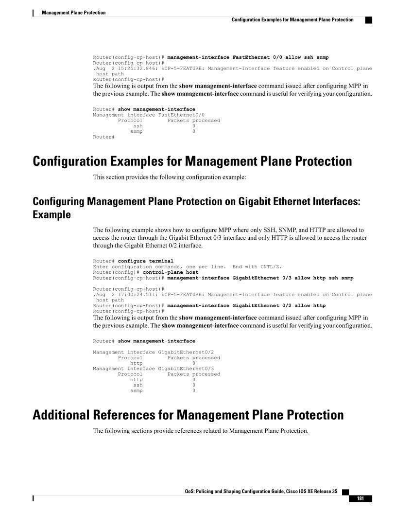
Router(config-cp-host)# management-interface FastEthernet 0/0 allow ssh snmpRouter(config-cp-host)#.Aug 2 15:25:32.846: %CP-5-FEATURE: Management-Interface feature enabled on Control planehost pathRouter(config-cp-host)#The following is output from the show management-interface command issued after configuring MPP inthe previous example. The showmanagement-interface command is useful for verifying your configuration.
Router# show management-interfaceManagement interface FastEthernet0/0
Protocol Packets processedssh 0snmp 0
Router#
Configuration Examples for Management Plane ProtectionThis section provides the following configuration example:
Configuring Management Plane Protection on Gigabit Ethernet Interfaces:Example
The following example shows how to configure MPP where only SSH, SNMP, and HTTP are allowed toaccess the router through the Gigabit Ethernet 0/3 interface and only HTTP is allowed to access the routerthrough the Gigabit Ethernet 0/2 interface.
Router# configure terminalEnter configuration commands, one per line. End with CNTL/Z.Router(config)# control-plane hostRouter(config-cp-host)# management-interface GigabitEthernet 0/3 allow http ssh snmp
Router(config-cp-host)#.Aug 2 17:00:24.511: %CP-5-FEATURE: Management-Interface feature enabled on Control planehost pathRouter(config-cp-host)# management-interface GigabitEthernet 0/2 allow httpRouter(config-cp-host)#The following is output from the show management-interface command issued after configuring MPP inthe previous example. The showmanagement-interface command is useful for verifying your configuration.
Router# show management-interface
Management interface GigabitEthernet0/2Protocol Packets processed
http 0Management interface GigabitEthernet0/3
Protocol Packets processedhttp 0ssh 0snmp 0
Additional References for Management Plane ProtectionThe following sections provide references related to Management Plane Protection.
QoS: Policing and Shaping Configuration Guide, Cisco IOS XE Release 3S 181
Management Plane ProtectionConfiguration Examples for Management Plane Protection

Related Documents
Document TitleRelated Topic
Cisco IOSNetworkManagementConfigurationGuideNetwork management
Cisco IOS Security Configuration GuideNetwork security
Control Plane Policing moduleControl Plane Policing
Control Plane Protection moduleControl Plane Protection
RFCs
TitleRFC
Operational Security Requirements for Large InternetService Provider (ISP) IP Network Infrastructure
RFC 3871
Technical Assistance
LinkDescription
http://www.cisco.com/techsupportThe Cisco Technical Support and Documentationwebsite contains thousands of pages of searchabletechnical content, including links to products,technologies, solutions, technical tips, and tools.Registered Cisco.com users can log in from this pageto access even more content.
Feature Information for Management Plane ProtectionThe following table provides release information about the feature or features described in this module. Thistable lists only the software release that introduced support for a given feature in a given software releasetrain. Unless noted otherwise, subsequent releases of that software release train also support that feature.
Use Cisco Feature Navigator to find information about platform support and Cisco software image support.To access Cisco Feature Navigator, go to www.cisco.com/go/cfn. An account on Cisco.com is not required.
Table 19: Feature Information for Management Plane Protection
Feature InformationReleasesFeature Name
Provides the capability to configuremanagement plane protection on avirtual template interface.
Cisco IOS XE Release 3.16SSMI over Virtual Template
QoS: Policing and Shaping Configuration Guide, Cisco IOS XE Release 3S182
Management Plane ProtectionFeature Information for Management Plane Protection

QoS: Policing and Shaping Configuration Guide, Cisco IOS XE Release 3S 183
Management Plane ProtectionFeature Information for Management Plane Protection

QoS: Policing and Shaping Configuration Guide, Cisco IOS XE Release 3S184
Management Plane ProtectionFeature Information for Management Plane Protection

C H A P T E R 16Class-Based Policing
Class-based policing allows you to control the maximum rate of traffic that is transmitted or received on aninterface. Class-based policing is often configured on interfaces at the edge of a network to limit traffic intoor out of the network.
• Finding Feature Information, page 185
• Information About Class-Based Policing, page 185
• Restrictions for Class-Based Policing, page 186
• How to Configure Class-Based Policing, page 187
• Configuration Examples for Class-Based Policing, page 192
• Additional References, page 194
• Feature Information for Class-Based Policing, page 196
Finding Feature InformationYour software release may not support all the features documented in this module. For the latest caveats andfeature information, see Bug Search Tool and the release notes for your platform and software release. Tofind information about the features documented in this module, and to see a list of the releases in which eachfeature is supported, see the feature information table at the end of this module.
Use Cisco Feature Navigator to find information about platform support and Cisco software image support.To access Cisco Feature Navigator, go to www.cisco.com/go/cfn. An account on Cisco.com is not required.
Information About Class-Based Policing
Class-Based Policing FunctionalityThe Class-Based Policing feature performs the following functions:
• Limits the input or output transmission rate of a class of traffic based on user-defined criteria.
QoS: Policing and Shaping Configuration Guide, Cisco IOS XE Release 3S 185

• Marks packets by setting the ATM Cell Loss Priority (CLP) bit, Frame Relay Discard Eligibility (DE)bit, IP precedence value, IP differentiated services code point (DSCP) value, MPLS experimental value,and quality of service (QoS) group.
Class-based policing allows you to control the maximum rate of traffic transmitted or received on an interface.The Class-Based Policing feature is applied when you attach a traffic policy that contains the class-basedpolicing configuration to an interface.
The Class-Based Policing feature works with a token bucket mechanism. There are currently two types oftoken bucket algorithms: a single token bucket algorithm and a two-token bucket algorithm. A single tokenbucket system is used when the violate-action option is not specified, and a two-token bucket system is usedwhen the violate-action option is specified.
Benefits of Class-Based Policing
Bandwidth Management Through Rate Limiting
Class-based policing allows you to control the maximum rate of traffic transmitted or received on an interface.Class-based policing is often configured on interfaces at the edge of a network to limit traffic into or out ofthe network. In most class-based policing configurations, traffic that falls within the rate parameters istransmitted, whereas traffic that exceeds the parameters is dropped or transmitted with a different priority.
Packet Marking
Packet marking allows you to partition your network into multiple priority levels or classes of service (CoS).A packet is marked and these markings can be used to identify and classify traffic for downstream devices.
• Use class-based policing to set the IP precedence or DSCP values for packets entering the network.Networking devices within your network can then use the adjusted IP precedence values to determinehow the traffic should be treated.
• Use class-based policing to assign packets to a QoS group. The router uses the QoS group to determinehow to prioritize packets.
Traffic can be marked without using the Class-Based Policing feature. If you want to mark traffic but do notwant to use class-based policing, see the “Marking Network Traffic” module.
Restrictions for Class-Based PolicingClass-based policing can be configured on an interface or a subinterface, but it is not supported on EtherChannelor tunnel interfaces.
Restrictions for the Cisco ASR 903 Router
• Class-based policing on subinterfaces is not supported.
• Policing is supported for ingress policy maps only.
• Hierarchical policing (policing at both parent level and child level) is not supported.
QoS: Policing and Shaping Configuration Guide, Cisco IOS XE Release 3S186
Class-Based PolicingBenefits of Class-Based Policing

How to Configure Class-Based Policing
Configuring a Traffic Policing Service Policy
SUMMARY STEPS
1. enable2. configure terminal3. class-map [match-all |match-any] class-map-name4. match ip precedence precedence-value5. exit6. policy-map policy-map-name7. class {class-name | class-default}8. police bps burst-normal burst-max conform-action action exceed-action action violate-action action9. exit10. exit11. interface interface-type interface-number12. service-policy {input | output} policy-map-name13. end
DETAILED STEPS
PurposeCommand or Action
Enables higher privilege levels, such as privileged EXEC mode.enableStep 1
Example:
Router> enable
• Enter your password if prompted.
Enters global configuration mode.configure terminal
Example:
Router# configure terminal
Step 2
Specifies the name of the class map to be created and enters QoSclass map configuration mode.
class-map [match-all |match-any]class-map-name
Step 3
Example:
Router(config)# class-map match-anyMATCH_PREC
• The class map defines the criteria to use to differentiate thetraffic. For example, you can use the class map to differentiatevoice traffic from data traffic, based on a series of matchcriteria defined using thematch command.
QoS: Policing and Shaping Configuration Guide, Cisco IOS XE Release 3S 187
Class-Based PolicingHow to Configure Class-Based Policing

PurposeCommand or Action
If thematch-all or match-any keyword is not specified,traffic must match all the match criteria to be classified aspart of the traffic class.
Note
Enables packet matching on the basis of the IP precedence valuesyou specify.
match ip precedence precedence-value
Example:
Router(config-cmap)# match ip precedence0
Step 4
You can enter up to four matching criteria, as numberabbreviation (0 to 7) or criteria names (critical, flash, andso on), in a single match statement.
Note
Returns to global configuration mode.exit
Example:
Router(config-cmap)# exit
Step 5
Creates or modifies a policy map that can be attached to one ormore interfaces to specify a service policy, and enters QoSpolicy-map configuration mode.
policy-map policy-map-name
Example:
Router(config)# policy-map POLICE-SETTING
Step 6
Specifies the name of the class whose policy you want to create orchange or specifies the default class (commonly known as the
class {class-name | class-default}
Example:
Router(config-pmap)# class MATCH_PREC
Step 7
class-default class) before you configure its policy, and enterspolicy-map class configuration mode.
Configures traffic policing according to burst sizes and any optionalactions specified.
police bps burst-normal burst-maxconform-action action exceed-action actionviolate-action action
Step 8
Conditional marking is not supported on the Cisco RSP3Module.
Note
Example:
Router(config-pmap-c)# police 8000 10001000 conform-action transmit exceed-actionset-qos-transmit 1 violate-action drop
(Optional) Exits policy-map class configuration mode.exit
Example:
Router(config-pmap-c)# exit
Step 9
(Optional) Exits QoS policy-map configuration mode.exit
Example:
Router(config-pmap)# exit
Step 10
QoS: Policing and Shaping Configuration Guide, Cisco IOS XE Release 3S188
Class-Based PolicingConfiguring a Traffic Policing Service Policy
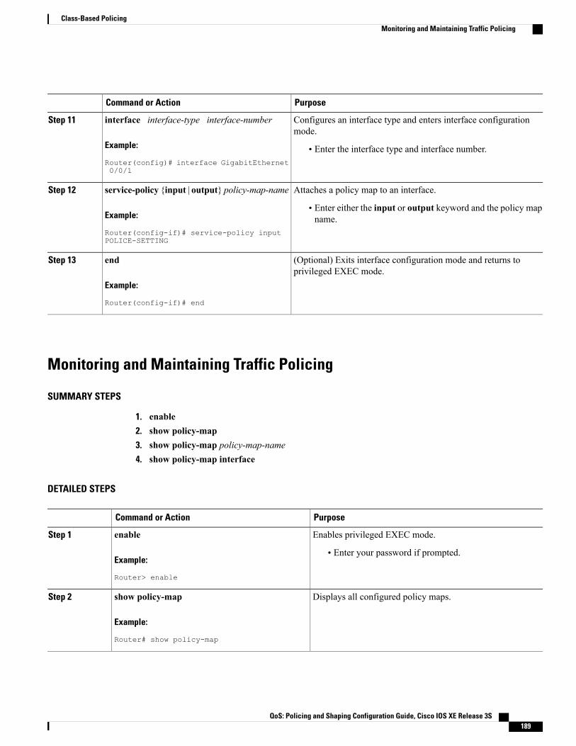
PurposeCommand or Action
Configures an interface type and enters interface configurationmode.
interface interface-type interface-number
Example:
Router(config)# interface GigabitEthernet0/0/1
Step 11
• Enter the interface type and interface number.
Attaches a policy map to an interface.service-policy {input | output} policy-map-nameStep 12
Example:
Router(config-if)# service-policy inputPOLICE-SETTING
• Enter either the input or output keyword and the policy mapname.
(Optional) Exits interface configuration mode and returns toprivileged EXEC mode.
end
Example:
Router(config-if)# end
Step 13
Monitoring and Maintaining Traffic Policing
SUMMARY STEPS
1. enable2. show policy-map3. show policy-map policy-map-name4. show policy-map interface
DETAILED STEPS
PurposeCommand or Action
Enables privileged EXEC mode.enableStep 1
Example:
Router> enable
• Enter your password if prompted.
Displays all configured policy maps.show policy-map
Example:
Router# show policy-map
Step 2
QoS: Policing and Shaping Configuration Guide, Cisco IOS XE Release 3S 189
Class-Based PolicingMonitoring and Maintaining Traffic Policing

PurposeCommand or Action
Displays the user-specified policy map.show policy-map policy-map-name
Example:
Router# show policy-map pmap
Step 3
Verifies that the Class-Based Policing feature is configuredon your interface. If the feature is configured on your interface.
show policy-map interface
Example:
Router# show policy-map interface
Step 4
• The command output displays policing statistics.
Verifying Class-Based Traffic PolicingUse the show policy-map interface command to verify that the Class-Based Policing feature is configuredon your interface. If the feature is configured on your interface, the show policy-map interface commandoutput displays policing statistics.
SUMMARY STEPS
1. enable2. show policy-map interface3. show policy-map interface type interface4. show policy-map interface type interface service instance service-instance number5. exit
DETAILED STEPS
PurposeCommand or Action
Enables privileged EXEC mode.enableStep 1
Example:
Router> enable
• Enter your password if prompted.
Verifies that the Class-Based Policing feature is configuredon your interface. If the feature is configured on yourinterface.
show policy-map interface
Example:
Router# show policy-map interface
Step 2
• The command output displays policing statistics.
QoS: Policing and Shaping Configuration Guide, Cisco IOS XE Release 3S190
Class-Based PolicingVerifying Class-Based Traffic Policing

PurposeCommand or Action
Displays traffic statistics for policies applied to a specificinterface.
show policy-map interface type interface
Example:
Router# show policy-map interfaceGigabitEthernet 0/0/1
Step 3
Displays the policy map information for a given serviceinstance under a port channel.
show policy-map interface type interface serviceinstance service-instance number
Example:
Router# show policy-map interfaceGigabitEthernet 0/0/1 service instance 1
Step 4
(Optional) Exits privileged EXEC mode.exit
Example:
Router# exit
Step 5
Example: Verifying Class-Based Traffic Policing
Router# show policy-map interfaceFastEthernet1/1/1service-policy output: xclass-map: a (match-all)0 packets, 0 bytes5 minute rate 0 bpsmatch: ip precedence 0police:1000000 bps, 10000 limit, 10000 extended limitconformed 0 packets, 0 bytes; action: transmitexceeded 0 packets, 0 bytes; action: dropconformed 0 bps, exceed 0 bps, violate 0 bps
Troubleshooting TipsCheck the interface type. Verify that class-based policing is supported on your interface. .
QoS: Policing and Shaping Configuration Guide, Cisco IOS XE Release 3S 191
Class-Based PolicingVerifying Class-Based Traffic Policing

Configuration Examples for Class-Based Policing
Example Configuring a Service Policy That Includes Traffic PolicingIn the following example, class-based policing is configured with the average rate at 8000 bits per second,the normal burst size at 1000 bytes, and the excess burst size at 1000 bytes for all packets leaving the interface.
class-map access-matchmatch access-group 1exitpolicy-map police-settingclass access-matchpolice 8000 1000 1000 conform-action transmit exceed-action set-qos-transmit 1
violate-action dropexitexitservice-policy output police-settingThe treatment of a series of packets leaving FastEthernet interface 1/1/1 depends on the size of the packet andthe number of bytes remaining in the conform and exceed token buckets. The series of packets are policedbased on the following rules:
• If the previous arrival of the packet was at T1 and the current arrival of the packet is at T, the bucket isupdated with T - T1 worth of bits based on the token arrival rate. The refill tokens are placed in theconform bucket. If the tokens overflow the conform bucket, the overflow tokens are placed in the exceedbucket. The token arrival rate is calculated as follows:
(time between packets < which is equal to T - T1 > * policer rate)/8 bytes
• If the number of bytes in the conform bucket is greater than the length of the packet (for example, B),then the packet conforms and B bytes should be removed from the bucket. If the packet conforms, Bbytes are removed from the conform bucket and the conform action is taken. The exceed bucket isunaffected in this scenario.
• If the number of bytes in the conform bucket is less than the length of the packet, but the number ofbytes in the exceed bucket is greater than the length of the packet (for example, B), the packet exceedsand B bytes are removed from the bucket.
• If the number bytes in the exceed bucket B is fewer than 0, the packet violates the rate and the violateaction is taken. The action is complete for the packet.
In this example, the initial token buckets starts full at 1000 bytes. If a 450-byte packet arrives, the packetconforms because enough bytes are available in the conform token bucket. The conform action (send) is takenby the packet, and 450 bytes are removed from the conform token bucket (leaving 550 bytes).
If the next packet arrives 0.25 seconds later, 250 bytes are added to the conform token bucket ((0.25 * 8000)/8),leaving 800 bytes in the conform token bucket. If the next packet is 900 bytes, the packet does not conformbecause only 800 bytes are available in the conform token bucket.
The exceed token bucket, which starts full at 1000 bytes (as specified by the excess burst size, is then checkedfor available bytes. Because enough bytes are available in the exceed token bucket, the exceed action (set theQoS transmit value of 1) is taken, and 900 bytes are taken from the exceed bucket (leaving 100 bytes in theexceed token bucket).
QoS: Policing and Shaping Configuration Guide, Cisco IOS XE Release 3S192
Class-Based PolicingConfiguration Examples for Class-Based Policing

If the next packet arrives 0.40 seconds later, 400 bytes are added to the token buckets ((.40 * 8000)/8).Therefore, the conform token bucket now has 1000 bytes (the maximum number of tokens available in theconform bucket, and 200 bytes overflow the conform token bucket (because only 200 bytes were needed tofill the conform token bucket to capacity). These overflow bytes are placed in the exceed token bucket, givingthe exceed token bucket 300 bytes.
If the arriving packet is 1000 bytes, the packet conforms because enough bytes are available in the conformtoken bucket. The conform action (transmit) is taken by the packet, and 1000 bytes are removed from theconform token bucket (leaving 0 bytes).
If the next packet arrives 0.20 seconds later, 200 bytes are added to the token bucket ((.20 * 8000)/8). Therefore,the conform bucket now has 200 bytes. If the arriving packet is 400 bytes, the packet does not conform becauseonly 200 bytes are available in the conform bucket. Similarly, the packet does not exceed because only 300bytes are available in the exceed bucket. Therefore, the packet violates and the violate action (drop) is taken.
Verifying Class-Based Traffic PolicingUse the show policy-map interface command to verify that the Class-Based Policing feature is configuredon your interface. If the feature is configured on your interface, the show policy-map interface commandoutput displays policing statistics:
Router# show policy-map interfaceFastEthernet1/1/1service-policy output: xclass-map: a (match-all)0 packets, 0 bytes5 minute rate 0 bpsmatch: ip precedence 0police:1000000 bps, 10000 limit, 10000 extended limitconformed 0 packets, 0 bytes; action: transmitexceeded 0 packets, 0 bytes; action: dropconformed 0 bps, exceed 0 bps, violate 0 bps
Use the show policy-map interface type nummber command to view the traffic statistics for policies appliedto that specific interface:
Router# show policy-map interface gigabitethernet 0/0/1GigabitEthernet0/0/1
Service-policy input: TUNNEL_MARKING
Class-map: MATCH_PREC (match-any)72417 packets, 25418367 bytes5 minute offered rate 0000 bps, drop rate 0000 bpsMatch: ip precedence 0QoS Setip precedence tunnel 3Marker statistics: Disabled
Class-map: MATCH_DSCP (match-any)0 packets, 0 bytes5 minute offered rate 0000 bps, drop rate 0000 bpsMatch: ip dscp default (0)QoS Setip dscp tunnel 3Marker statistics: Disabled
Class-map: class-default (match-any)346462 packets, 28014400 bytes5 minute offered rate 0000 bps, drop rate 0000 bpsMatch: any
QoS: Policing and Shaping Configuration Guide, Cisco IOS XE Release 3S 193
Class-Based PolicingVerifying Class-Based Traffic Policing
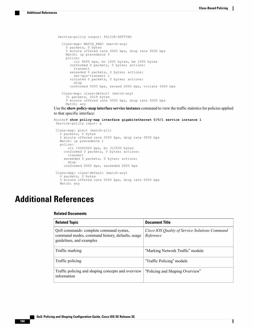
Service-policy output: POLICE-SETTING
Class-map: MATCH_PREC (match-any)0 packets, 0 bytes5 minute offered rate 0000 bps, drop rate 0000 bpsMatch: ip precedence 0police:
cir 8000 bps, bc 1000 bytes, be 1000 bytesconformed 0 packets, 0 bytes; actions:transmit
exceeded 0 packets, 0 bytes; actions:set-qos-transmit 1
violated 0 packets, 0 bytes; actions:drop
conformed 0000 bps, exceed 0000 bps, violate 0000 bps
Class-map: class-default (match-any)31 packets, 2019 bytes5 minute offered rate 0000 bps, drop rate 0000 bpsMatch: any
Use the show policy-map interface service instance command to view the traffic statistics for policies appliedto that specific interface:Router# show policy-map interface gigabitethernet 0/0/1 service instance 1Service-policy input: p
Class-map: prec1 (match-all)0 packets, 0 bytes5 minute offered rate 0000 bps, drop rate 0000 bpsMatch: ip precedence 1police:
cir 10000000 bps, bc 312500 bytesconformed 0 packets, 0 bytes; actions:transmit
exceeded 0 packets, 0 bytes; actions:drop
conformed 0000 bps, exceeded 0000 bps
Class-map: class-default (match-any)0 packets, 0 bytes5 minute offered rate 0000 bps, drop rate 0000 bpsMatch: any
Additional ReferencesRelated Documents
Document TitleRelated Topic
Cisco IOS Quality of Service Solutions CommandReference
QoS commands: complete command syntax,command modes, command history, defaults, usageguidelines, and examples
“Marking Network Traffic” moduleTraffic marking
“Traffic Policing” moduleTraffic policing
“Policing and Shaping Overview”Traffic policing and shaping concepts and overviewinformation
QoS: Policing and Shaping Configuration Guide, Cisco IOS XE Release 3S194
Class-Based PolicingAdditional References
Document TitleRelated Topic
“Applying QoS Features Using the MQC” moduleModular Quality of Service Command-Line Interface(MQC)
Standards
TitleStandard
--None
MIBs
MIBs LinkMIB
To locate and downloadMIBs for selected platforms,Cisco IOSXE Software releases, and feature sets, useCisco MIB Locator found at the following URL:
http://www.cisco.com/go/mibs
Class-Based Quality of Service MIB
• CISCO-CLASS-BASED-QOS-MIB
• CISCO-CLASS-BASED-QOS-CAPABILITY-MIB
RFCs
TitleRFC
A Single Rate Three Color MarkerRFC 2697
Technical Assistance
LinkDescription
http://www.cisco.com/cisco/web/support/index.htmlThe Cisco Support and Documentation websiteprovides online resources to download documentation,software, and tools. Use these resources to install andconfigure the software and to troubleshoot and resolvetechnical issues with Cisco products and technologies.Access to most tools on the Cisco Support andDocumentation website requires a Cisco.com user IDand password.
QoS: Policing and Shaping Configuration Guide, Cisco IOS XE Release 3S 195
Class-Based PolicingAdditional References

Feature Information for Class-Based PolicingThe following table provides release information about the feature or features described in this module. Thistable lists only the software release that introduced support for a given feature in a given software releasetrain. Unless noted otherwise, subsequent releases of that software release train also support that feature.
Use Cisco Feature Navigator to find information about platform support and Cisco software image support.To access Cisco Feature Navigator, go to www.cisco.com/go/cfn. An account on Cisco.com is not required.
Table 20: Feature Information for Class-Based Policing
Feature InformationReleasesFeature Name
This feature was introduced onCisco ASR 1000 Series Routers.
In Cisco IOS XE Release 3.5S,support was added for the CiscoASR 903 Router.
In Cisco IOS XE Release 3.16,support was added for the CiscoASR 900 RSP3 Module.
The following command wasintroduced or modified: police.
Cisco IOS XE Release 2.1
Cisco IOS XE Release 3.5S
Cisco IOS XE Release 3.16
Class-Based Policing
QoS: Policing and Shaping Configuration Guide, Cisco IOS XE Release 3S196
Class-Based PolicingFeature Information for Class-Based Policing

C H A P T E R 17QoS Percentage-Based Policing
The QoS Percentage-Based Policing feature allows you to configure traffic policing and traffic shaping onthe basis of a percentage of bandwidth available on the interface. This feature also allows you to specify thecommitted burst (bc) size and the excess burst (be) size (used for configuring traffic policing) in milliseconds(ms). Configuring traffic policing in this manner enables you to use the same policymap for multiple interfaceswith differing amounts of bandwidth.
• Finding Feature Information, page 197
• Information About QoS Percentage-Based Policing, page 197
• How to Configure QoS Percentage-Based Policing, page 199
• Configuration Examples for QoS Percentage-Based Policing, page 203
• Additional References, page 205
• Feature Information for QoS Percentage-Based Policing, page 207
Finding Feature InformationYour software release may not support all the features documented in this module. For the latest caveats andfeature information, see Bug Search Tool and the release notes for your platform and software release. Tofind information about the features documented in this module, and to see a list of the releases in which eachfeature is supported, see the feature information table at the end of this module.
Use Cisco Feature Navigator to find information about platform support and Cisco software image support.To access Cisco Feature Navigator, go to www.cisco.com/go/cfn. An account on Cisco.com is not required.
Information About QoS Percentage-Based Policing
Benefits for QoS Percentage-Based PolicingThis feature provides the ability to configure traffic policing on the basis of a percentage of bandwidth availableon an interface, and it allows you to specify burst sizes in milliseconds. Configuring traffic policing in this
QoS: Policing and Shaping Configuration Guide, Cisco IOS XE Release 3S 197

manner enables you to use the same policy map for multiple interfaces with differing amounts of bandwidth.That is, you do not have to recalculate the bandwidth for each interface or configure a different policy mapfor each type of interface.
Configuration of Class and Policy Maps for QoS Percentage-Based PolicingTo configure the QoS: Percentage-Based Policing feature, you must define a traffic class, configure a policymap, and then attach that policy map to the appropriate interface.
The MQC is a command-line interface that allows you to define traffic classes, create and configure trafficpolicies (policy maps), and then attach these traffic policies to interfaces.
In the MQC, the class-map command is used to define a traffic class (which is then associated with a trafficpolicy). The purpose of a traffic class is to classify traffic.
The MQC consists of the following three processes:
• Defining a traffic class with the class-map command.
• Creating a traffic policy by associating the traffic class with one or more QoS features (using thepolicy-map command).
• Attaching the traffic policy to the interface with the service-policy command.
A traffic class contains three major elements: a name, a series of match commands, and, if more than onematch command exists in the traffic class, an instruction on how to evaluate thesematch commands (that is,match-all or match-any). The traffic class is named in the class-map command line; for example, if you enterthe class-map cisco command while configuring the traffic class in the CLI, the traffic class would be named"cisco".
Thematch commands are used to specify various criteria for classifying packets. Packets are checked todetermine whether they match the criteria specified in thematch commands. If a packet matches the specifiedcriteria, that packet is considered a member of the class and is forwarded according to the QoS specificationsset in the traffic policy. Packets that fail to meet any of the matching criteria are classified as members of thedefault traffic class.
Traffic Regulation Mechanisms and Bandwidth PercentagesCisco IOS XE quality of service (QoS) offers two kinds of traffic regulation mechanisms--traffic policingand traffic shaping. A traffic policer typically drops traffic that violates a specific rate. A traffic shaper typicallydelays excess traffic using a buffer to hold packets and shapes the flow when the data rate to a queue is higherthan expected.
Traffic shaping and traffic policing can work in tandem and can be configured in a class map. Class mapsorganize data packets into specific categories ("classes") that can, in turn, receive a user-defined QoS treatmentwhen used in policy maps (sometimes referred to as "service policies").
Before this feature, traffic policing and traffic shaping were configured on the basis of a user-specified amountof bandwidth available on the interface. Policy maps were then configured on the basis of that specific amountof bandwidth, meaning that separate policy maps were required for each interface.
This feature provides the ability to configure traffic policing and traffic shaping on the basis of a percentageof bandwidth available on the interface. Configuring traffic policing and traffic shaping in this manner enablescustomers to use the same policy map for multiple interfaces with differing amounts of bandwidth.
QoS: Policing and Shaping Configuration Guide, Cisco IOS XE Release 3S198
QoS Percentage-Based PolicingConfiguration of Class and Policy Maps for QoS Percentage-Based Policing

Configuring traffic policing and shaping on the basis of a percentage of bandwidth is accomplished by usingthe police (percent) and shape (percent) commands.
Burst Size in Milliseconds OptionThe purpose of the burst parameters (bc and be) is to drop packets gradually and to avoid tail drop. Settingsufficiently high burst values helps to ensure good throughput.
This feature allows you the option of specifying the committed burst (bc) size and the extended burst (be) asmilliseconds (ms) of the class bandwidth when you configure traffic policing. The number of milliseconds isused to calculate the number of bytes that will be used by the QoS: Percentage-Based Policing feature.
Specifying these burst sizes in milliseconds is accomplished by using the bc and be keywords (and theirassociated arguments) of the police (percent) and shape (percent) commands.
How to Configure QoS Percentage-Based Policing
Configuring a Class and Policy Map for Percentage-Based Policing
SUMMARY STEPS
1. enable2. configure terminal3. policy-map policy-name4. class {class-name class-default}5. police cir percent percentage [burst-in-ms] [bc conform-burst-in-msecms] [be peak-burst-in-msec
ms] [ pir percent percent]6. exit
DETAILED STEPS
PurposeCommand or Action
Enables privileged EXEC mode.enableStep 1
Example:
Router> enable
• Enter your password if prompted.
Enters global configuration mode.configure terminal
Example:
Router# configure terminal
Step 2
QoS: Policing and Shaping Configuration Guide, Cisco IOS XE Release 3S 199
QoS Percentage-Based PolicingBurst Size in Milliseconds Option

PurposeCommand or Action
Specifies the name of the policy map to be created. Enterspolicy-map configuration mode.
policy-map policy-name
Example:
Router(config)# policy-map
Step 3
• Enter the policy map name.
policy1
Specifies the class so that you can configure or modify itspolicy. Enters policy-map class configuration mode.
class {class-name class-default}
Example:
Router(config-pmap)# class class1
Step 4
• Enter the class name or specify the default class(class-default).
Configures traffic policing on the basis of the specifiedbandwidth percentage and optional burst sizes. Enterspolicy-map class police configuration mode.
police cir percent percentage [burst-in-ms][bc conform-burst-in-msecms] [be peak-burst-in-msecms] [ pir percent percent]
Step 5
Example:
Router(config-pmap-c)# police cir percent 20bc 300 ms be 400 ms pir percent 40
• Enter the bandwidth percentage and optional burst sizes.
Exits policy-map class police configuration mode.exit
Example:
Router(config-pmap-c-police)# exit
Step 6
Attaching the Policy Map to an Interface for Percentage-Based Policing
SUMMARY STEPS
1. enable2. configure terminal3. interface type number4. pvc [name] vpi / vci [ilmi | qsaal | smds]5. service-policy {input| output} policy-map-name6. end
QoS: Policing and Shaping Configuration Guide, Cisco IOS XE Release 3S200
QoS Percentage-Based PolicingAttaching the Policy Map to an Interface for Percentage-Based Policing

DETAILED STEPS
PurposeCommand or Action
Enables privileged EXEC mode.enableStep 1
Example:
Router> enable
• Enter your password if prompted.
Enters global configuration mode.configure terminal
Example:
Router# configure terminal
Step 2
Configures an interface (or subinterface) type and enters interface configurationmode.
interface type number
Example:
Router(config)#
Step 3
• Enter the interface type number.
Depending on the needs of your network, you may need to attach thepolicy map to a subinterface, an ATM PVC, a Frame Relay DLCI,or other type of interface.
Noteinterface serial4/0/0
(Optional) Creates or assigns a name to an ATM PVC and specifies theencapsulation type on an ATM PVC. Enters ATM VC configuration mode.
pvc [name] vpi / vci [ilmi | qsaal | smds]
Example:
Router(config-if)# pvc cisco 0/16ilmi
Step 4
This step is required only if you are attaching the policy map to anATM PVC. If you are not attaching the policy map to an ATM PVC,skip this step and proceed with Attaching the Policy Map to anInterface for Percentage-Based Policing.
Note
Specifies the name of the policy map to be attached to the input or outputdirection of the interface.
service-policy {input| output}policy-map-name
Step 5
Example:
Router(config-if)#
Policy maps can be configured on ingress or egress routers. They canalso be attached in the input or output direction of an interface. Thedirection (input or output) and the router (ingress or egress) to whichthe policy map should be attached varies according your networkconfiguration. When using the service-policy command to attach thepolicy map to an interface, be sure to choose the router and theinterface direction that are appropriate for your network configuration.
Note
service-policy input policy1
Example:
• Enter the policy map name.
(Optional) Exits interface configuration mode.end
Example:
Router(config-if)# end
Step 6
QoS: Policing and Shaping Configuration Guide, Cisco IOS XE Release 3S 201
QoS Percentage-Based PolicingAttaching the Policy Map to an Interface for Percentage-Based Policing
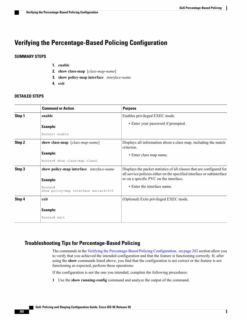
Verifying the Percentage-Based Policing Configuration
SUMMARY STEPS
1. enable2. show class-map [class-map-name]3. show policy-map interface interface-name4. exit
DETAILED STEPS
PurposeCommand or Action
Enables privileged EXEC mode.enableStep 1
Example:
Router> enable
• Enter your password if prompted.
Displays all information about a class map, including the matchcriterion.
show class-map [class-map-name]
Example:
Router# show class-map class1
Step 2
• Enter class map name.
Displays the packet statistics of all classes that are configured forall service policies either on the specified interface or subinterfaceor on a specific PVC on the interface.
show policy-map interface interface-name
Example:
Router#show policy-map interface serial4/0/0
Step 3
• Enter the interface name.
(Optional) Exits privileged EXEC mode.exit
Example:
Router# exit
Step 4
Troubleshooting Tips for Percentage-Based PolicingThe commands in the Verifying the Percentage-Based Policing Configuration, on page 202 section allow youto verify that you achieved the intended configuration and that the feature is functioning correctly. If, afterusing the show commands listed above, you find that the configuration is not correct or the feature is notfunctioning as expected, perform these operations:
If the configuration is not the one you intended, complete the following procedures:
1 Use the show running-config command and analyze the output of the command.
QoS: Policing and Shaping Configuration Guide, Cisco IOS XE Release 3S202
QoS Percentage-Based PolicingVerifying the Percentage-Based Policing Configuration
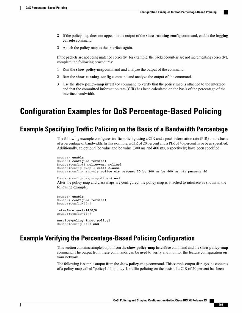
2 If the policy map does not appear in the output of the show running-config command, enable the loggingconsole command.
3 Attach the policy map to the interface again.
If the packets are not beingmatched correctly (for example, the packet counters are not incrementing correctly),complete the following procedures:
1 Run the show policy-mapcommand and analyze the output of the command.
2 Run the show running-config command and analyze the output of the command.
3 Use the show policy-map interface command to verify that the policy map is attached to the interfaceand that the committed information rate (CIR) has been calculated on the basis of the percentage of theinterface bandwidth.
Configuration Examples for QoS Percentage-Based Policing
Example Specifying Traffic Policing on the Basis of a Bandwidth PercentageThe following example configures traffic policing using a CIR and a peak information rate (PIR) on the basisof a percentage of bandwidth. In this example, a CIR of 20 percent and a PIR of 40 percent have been specified.Additionally, an optional bc value and be value (300 ms and 400 ms, respectively) have been specified.
Router> enableRouter# configure terminalRouter(config)# policy-map policy1Router(config-pmap)# class class1Router(config-pmap-c)# police cir percent 20 bc 300 ms be 400 ms pir percent 40
Router(config-pmap-c-police)# endAfter the policy map and class maps are configured, the policy map is attached to interface as shown in thefollowing example.
Router> enableRouter# configure terminalRouter(config-if)#
interface serial4/0/0Router(config-if)#
service-policy input policy1Router(config-if)# end
Example Verifying the Percentage-Based Policing ConfigurationThis section contains sample output from the show policy-map interface command and the show policy-mapcommand. The output from these commands can be used to verify and monitor the feature configuration onyour network.
The following is sample output from the show policy-map command. This sample output displays the contentsof a policy map called "policy1." In policy 1, traffic policing on the basis of a CIR of 20 percent has been
QoS: Policing and Shaping Configuration Guide, Cisco IOS XE Release 3S 203
QoS Percentage-Based PolicingConfiguration Examples for QoS Percentage-Based Policing
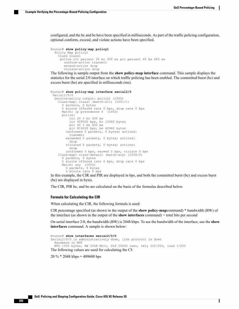
configured, and the bc and be have been specified in milliseconds. As part of the traffic policing configuration,optional conform, exceed, and violate actions have been specified.
Router# show policy-map policy1Policy Map policy1Class class1police cir percent 20 bc 300 ms pir percent 40 be 400 msconform-action transmitexceed-action dropviolate-action drop
The following is sample output from the show policy-map interface command. This sample displays thestatistics for the serial 2/0 interface on which traffic policing has been enabled. The committed burst (bc) andexcess burst (be) are specified in milliseconds (ms).
Router# show policy-map interface serial2/0Serial2/0/0Service-policy output: policy1 (1050)Class-map: class1 (match-all) (1051/1)0 packets, 0 bytes5 minute offered rate 0 bps, drop rate 0 bpsMatch: ip precedence 0 (1052)police:
cir 20 % bc 300 mscir 409500 bps, bc 15360 bytespir 40 % be 400 mspir 819000 bps, be 40960 bytes
conformed 0 packets, 0 bytes; actions:transmit
exceeded 0 packets, 0 bytes; actions:drop
violated 0 packets, 0 bytes; actions:drop
conformed 0 bps, exceed 0 bps, violate 0 bpsClass-map: class-default (match-any) (1054/0)0 packets, 0 bytes5 minute offered rate 0 bps, drop rate 0 bpsMatch: any (1055)0 packets, 0 bytes5 minute rate 0 bps
In this example, the CIR and PIR are displayed in bps, and both the committed burst (bc) and excess burst(be) are displayed in bytes.
The CIR, PIR bc, and be are calculated on the basis of the formulas described below.
Formula for Calculating the CIR
When calculating the CIR, the following formula is used:
CIR percentage specified (as shown in the output of the show policy-mapcommand) * bandwidth (BW) ofthe interface (as shown in the output of the show interfaces command) = total bits per second
On serial interface 2/0, the bandwidth (BW) is 2048 kbps. To see the bandwidth of the interface, use the showinterfaces command. A sample is shown below:
Router# show interfaces serial2/0/0Serial2/0/0 is administratively down, line protocol is downHardware is M4TMTU 1500 bytes, BW 2048 Kbit, DLY 20000 usec, rely 255/255, load 1/255
The following values are used for calculating the CI:
20 % * 2048 kbps = 409600 bps
QoS: Policing and Shaping Configuration Guide, Cisco IOS XE Release 3S204
QoS Percentage-Based PolicingExample Verifying the Percentage-Based Policing Configuration

Formula for Calculating the PIR
When calculating the PIR, the following formula is used:
PIR percentage specified (as shown in the output of the show policy-mapcommand) * bandwidth (BW) ofthe interface (as shown in the output of the show interfaces command) = total bits per second
On serial interface 2/0/0, the bandwidth (BW) is 2048 kbps. To see the bandwidth of the interface, use theshow interfaces command. A sample is shown below:
Router# show interfaces serial2/0Serial2/0/0 is administratively down, line protocol is downHardware is M4TMTU 1500 bytes, BW 2048 Kbit, DLY 20000 usec, rely 255/255, load 1/255
The following values are used for calculating the PIR:
40 % * 2048 kbps = 819200 bps
Discrepancies between this total and the total shown in the output of the show policy-map interfacecommand can be attributed to a rounding calculation or to differences associated with the specific interfaceconfiguration.
Note
Formula for Calculating the Committed Burst (bc)
When calculating the bc, the following formula is used:
The bc in milliseconds (as shown in the show policy-map command) * the CIR in bits per seconds = totalnumber bytes
The following values are used for calculating the bc:
(300 ms * 409600 bps) / 8 = 15360 bytes
Formula for Calculating the Excess Burst (be)
When calculating the bc and the be, the following formula is used:
The be in milliseconds (as shown in the show policy-map command) * the PIR in bits per seconds = totalnumber bytes
The following values are used for calculating the be:
400 ms * 819200 bps = 40960 bytes
Additional ReferencesRelated Documents
Document TitleRelated Topic
Cisco IOS Quality of Service Solutions CommandReference
QoS commands: complete command syntax,command modes, command history, defaults, usageguidelines, and examples
QoS: Policing and Shaping Configuration Guide, Cisco IOS XE Release 3S 205
QoS Percentage-Based PolicingAdditional References
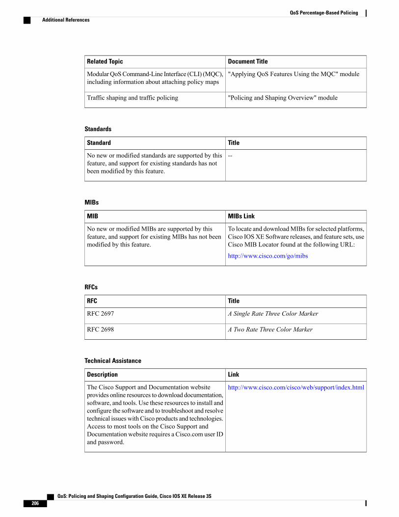
Document TitleRelated Topic
"Applying QoS Features Using the MQC" moduleModularQoSCommand-Line Interface (CLI) (MQC),including information about attaching policy maps
"Policing and Shaping Overview" moduleTraffic shaping and traffic policing
Standards
TitleStandard
--No new or modified standards are supported by thisfeature, and support for existing standards has notbeen modified by this feature.
MIBs
MIBs LinkMIB
To locate and downloadMIBs for selected platforms,Cisco IOSXE Software releases, and feature sets, useCisco MIB Locator found at the following URL:
http://www.cisco.com/go/mibs
No new or modified MIBs are supported by thisfeature, and support for existing MIBs has not beenmodified by this feature.
RFCs
TitleRFC
A Single Rate Three Color MarkerRFC 2697
A Two Rate Three Color MarkerRFC 2698
Technical Assistance
LinkDescription
http://www.cisco.com/cisco/web/support/index.htmlThe Cisco Support and Documentation websiteprovides online resources to download documentation,software, and tools. Use these resources to install andconfigure the software and to troubleshoot and resolvetechnical issues with Cisco products and technologies.Access to most tools on the Cisco Support andDocumentation website requires a Cisco.com user IDand password.
QoS: Policing and Shaping Configuration Guide, Cisco IOS XE Release 3S206
QoS Percentage-Based PolicingAdditional References
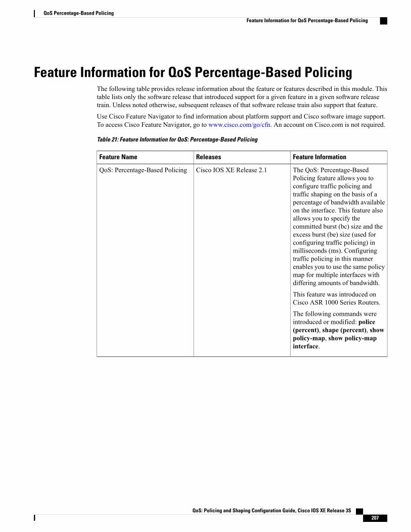
Feature Information for QoS Percentage-Based PolicingThe following table provides release information about the feature or features described in this module. Thistable lists only the software release that introduced support for a given feature in a given software releasetrain. Unless noted otherwise, subsequent releases of that software release train also support that feature.
Use Cisco Feature Navigator to find information about platform support and Cisco software image support.To access Cisco Feature Navigator, go to www.cisco.com/go/cfn. An account on Cisco.com is not required.
Table 21: Feature Information for QoS: Percentage-Based Policing
Feature InformationReleasesFeature Name
The QoS: Percentage-BasedPolicing feature allows you toconfigure traffic policing andtraffic shaping on the basis of apercentage of bandwidth availableon the interface. This feature alsoallows you to specify thecommitted burst (bc) size and theexcess burst (be) size (used forconfiguring traffic policing) inmilliseconds (ms). Configuringtraffic policing in this mannerenables you to use the same policymap for multiple interfaces withdiffering amounts of bandwidth.
This feature was introduced onCisco ASR 1000 Series Routers.
The following commands wereintroduced or modified: police(percent), shape (percent), showpolicy-map, show policy-mapinterface.
Cisco IOS XE Release 2.1QoS: Percentage-Based Policing
QoS: Policing and Shaping Configuration Guide, Cisco IOS XE Release 3S 207
QoS Percentage-Based PolicingFeature Information for QoS Percentage-Based Policing

QoS: Policing and Shaping Configuration Guide, Cisco IOS XE Release 3S208
QoS Percentage-Based PolicingFeature Information for QoS Percentage-Based Policing

C H A P T E R 18Two-Rate Policer
This module describes the Two-Rate Policer feature and explains how to configure it.
History for the Two-Rate Policer Feature
ModificationRelease
This feature was implemented on Cisco ASR 1000Series Routers.
Cisco IOS XE Release 2.1
Finding Support Information for Cisco IOS XE Software Images
Use Cisco Feature Navigator to find information about platform support and Cisco IOS XE Software imagesupport. To access Cisco Feature Navigator, go to http://www.cisco.com/go/cfn . An account on Cisco.comis not required.
• Finding Feature Information, page 209
• Feature Overview, page 210
• Prerequisites for Two-Rate Traffic Policing, page 211
• Configuration Tasks, page 211
• Monitoring and Maintaining the Two-Rate Policer, page 213
• Configuration Examples, page 213
• Additional References, page 214
• Feature Information for Two-Rate Policer, page 215
Finding Feature InformationYour software release may not support all the features documented in this module. For the latest caveats andfeature information, see Bug Search Tool and the release notes for your platform and software release. Tofind information about the features documented in this module, and to see a list of the releases in which eachfeature is supported, see the feature information table at the end of this module.
QoS: Policing and Shaping Configuration Guide, Cisco IOS XE Release 3S 209
Use Cisco Feature Navigator to find information about platform support and Cisco software image support.To access Cisco Feature Navigator, go to www.cisco.com/go/cfn. An account on Cisco.com is not required.
Feature OverviewWhen configured, an ATM switch at the network side of a user-to-network (UNI) interface polices the flowof cells in the forward (into the network) direction of a virtual connection. These traffic policing mechanismsare known as usage parameter control (UPC).With UPC, the switch determines whether received cells complywith the negotiated traffic management values and takes one of the following actions on violating cells:
• Pass the cell without changing the cell loss priority (CLP) bit in the cell header.
• Tag the cell with a CLP bit value of 1.
• Drop (discard) the cell.
The SVC/SoftPVC feature enables you to specify which traffic to police, based on service category, onswitched virtual circuits (SVCs) or terminating VCs on the destination end of a soft VC.
Benefits
Bandwidth Management Through Rate Limiting
Traffic policing allows you to control the maximum rate of traffic transmitted or received on an interface.Traffic policing is often configured on interfaces at the edge of a network to limit traffic into or out of thenetwork. In most Traffic Policing configurations, traffic that falls within the rate parameters is transmitted,whereas traffic that exceeds the parameters is dropped or transmitted with a different priority.
Packet Marking
Packet marking allows you to partition your network into multiple priority levels or classes of service (CoS).A packet is marked and these markings can be used to identify and classify traffic for downstream devices.In some cases, such as ATM Cell Loss Priority (CLP) marking or Frame Relay Discard Eligibility (DE)marking, the marking is used to classify traffic.
• Use traffic policing to set the IP precedence or DSCP values for packets entering the network. Networkingdevices within your network can then use the adjusted IP precedence values to determine how the trafficshould be treated. For example, the Weighted Random Early Detection (WRED) feature uses the IPprecedence values to determine the probability that a packet will be dropped.
• Use traffic policing to assign packets to a QoS group. The router uses the QoS group to determine howto prioritize packets within the router.
Traffic can be marked without using the Traffic Policing feature. If you want to mark traffic but do not wantto use Traffic Policing, see the "Marking Network Traffic" module.
Packet Prioritization for Frame Relay Frames
The Traffic Policing feature allows users to mark the Frame Relay DE bit of the Frame Relay frame. TheFrame Relay DE bit is one bit and, therefore, can be set to either 0 or 1. In congested environments, frameswith the DE bit set to 1 are discarded before frames with the DE bit set to 0.
QoS: Policing and Shaping Configuration Guide, Cisco IOS XE Release 3S210
Two-Rate PolicerFeature Overview

Packet Prioritization for ATM Cells
The Traffic Policing feature allows users to mark the ATM CLP bit in ATM cells. The ATM CLP bit is usedto prioritize packets in ATM networks. The ATM CLP bit is one bit and, therefore, can be set to either 0 or1. In congested environments, cells with the ATM CLP bit set to 1 are discarded before cells with the ATMCLP bit set to 0.
Restrictions for Two-Rate PolicingThe following restrictions apply to the Two-Rate Policer:
• Two-rate policing can be configured on an interface, a subinterface, a Frame Relay data-link connectionidentifier (DLCI), and an ATM permanent virtual circuit (PVC).
• Two-rate policing is not supported on EtherChannel or tunnel interfaces.
Prerequisites for Two-Rate Traffic PolicingTo configure the Two-Rate Policer, a traffic class and a service policy must be created, and the service policymust be attached to a specified interface.
Configuration TasksSee the following sections for configuration tasks for the Two-Rate Policer feature.
Configuring the Two-Rate PolicerPurposeCommand
Specifies that both the CIR and the PIR are to be usedfor two-rate traffic policing, and specifies multipleactions applied to packets marked as conforming to,exceeding, or violating a specific rate. Use one lineper action that you want to specify. Enters policy-mapclass police configuration mode.
The bc and be keywords and their associatedarguments (conform-burst and peak-burst ,respectively) are optional.
Router(config-pmap-c)#police circir [bcconform-burst] pir pir
[bepeak-burst][conform-action action[exceed-action action[violate-action action]]]
Although not required for configuring the Two-Rate Policer, the command syntax of the police commandalso allows you to specify the action to be taken on a packet when you enable an optional action argument.The resulting action corresponding to the keyword choices are listed in Table 1 .
QoS: Policing and Shaping Configuration Guide, Cisco IOS XE Release 3S 211
Two-Rate PolicerRestrictions for Two-Rate Policing

Table 22: police Command Action Keywords
Resulting ActionKeyword
Drops the packet.drop
Sets the ATM CLP bit from 0 to 1 on the ATM celland sends the packet with the ATM CLP bit set to 1.
set-clp-transmit
Sets the IP DSCP value and sends the packet with thenew IP DSCP value setting.
set-dscp-transmit new-dscp
Sets the Frame Relay DE bit from 0 to 1 on the FrameRelay frame and sends the packet with the DE bit setto 1.
set-frde-transmit
Sets the MPLS experimental bits from 0 to 7 andsends the packet with the new MPLS experimentalbit value setting.
set-mpls-exp-transmit
Sets the IP precedence and sends the packet with thenew IP precedence value setting.
set-prec-transmit new-prec
Sets the QoS group value and sends the packet withthe new QoS group value setting.
set-qos-transmit new-qos
Sends the packet with no alteration.transmit
Verifying the Two-Rate Policer ConfigurationPurposeCommand
Displays statistics and configurations of all input andoutput policies attached to an interface.Router#
show policy-map interface
QoS: Policing and Shaping Configuration Guide, Cisco IOS XE Release 3S212
Two-Rate PolicerVerifying the Two-Rate Policer Configuration

Troubleshooting Tips
Monitoring and Maintaining the Two-Rate PolicerPurposeCommand
Displays all configured policy maps.Router#show policy-map
Displays the user-specified policy map.Router# show policy-map policy-map-name
Displays statistics and configurations of all input andoutput policies that are attached to an interface.Router#
show policy-map interface
Configuration Examples
Example Limiting the Traffic Using a Policer ClassIn this example, the Two-Rate Policer is configured on a class to limit traffic to an average committed rate of500 kbps and a peak rate of 1 Mbps.
Router(config)# class-map policeRouter(config-cmap)# match access-group 101Router(config-cmap)# policy-map policy1Router(config-pmap)# class policeRouter(config-pmap-c)# police cir 500000 bc 10000 pir 1000000 be 10000 conform-actiontransmit exceed-action set-prec-transmit 2 violate-action dropRouter(config)# interface serial3/0/0Router(config-if)# service-policy output policy1Router(config-if)# endRouter# show policy-map policy1Policy Map policy1Class policepolice cir 500000 conform-burst 10000 pir 1000000 peak-burst 10000 conform-action transmit
exceed-action set-prec-transmit 2 violate-action dropTraffic marked as conforming to the average committed rate (500 kbps) will be sent as is. Traffic marked asexceeding 500 kbps, but not exceeding 1 Mbps, will be marked with IP Precedence 2 and then sent. All trafficexceeding 1 Mbps will be dropped. The burst parameters are set to 10,000 bytes.
In the following example, 1.25 Mbps of traffic is sent ("offered") to a policer class.
Router# show policy-map interface serial3/0/0Serial3/0/0Service-policy output: policy1Class-map: police (match all)148803 packets, 36605538 bytes30 second offered rate 1249000 bps, drop rate 249000 bpsMatch: access-group 101police:
QoS: Policing and Shaping Configuration Guide, Cisco IOS XE Release 3S 213
Two-Rate PolicerTroubleshooting Tips
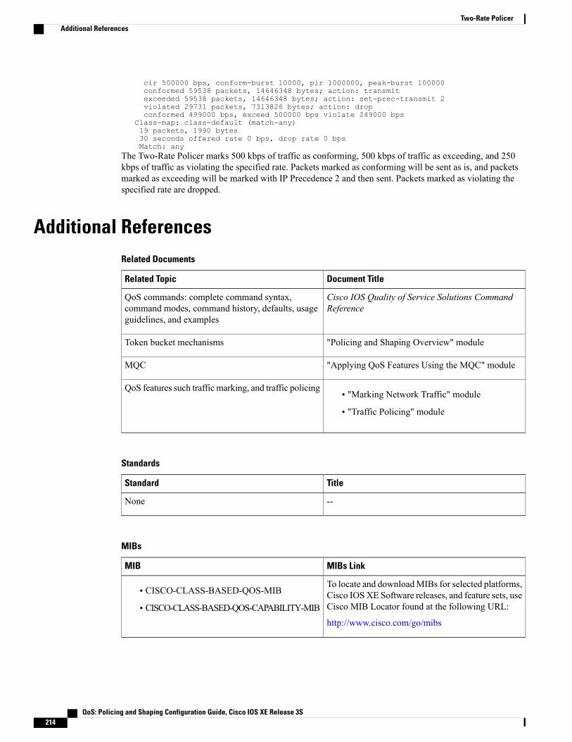
cir 500000 bps, conform-burst 10000, pir 1000000, peak-burst 100000conformed 59538 packets, 14646348 bytes; action: transmitexceeded 59538 packets, 14646348 bytes; action: set-prec-transmit 2violated 29731 packets, 7313826 bytes; action: dropconformed 499000 bps, exceed 500000 bps violate 249000 bps
Class-map: class-default (match-any)19 packets, 1990 bytes30 seconds offered rate 0 bps, drop rate 0 bpsMatch: any
The Two-Rate Policer marks 500 kbps of traffic as conforming, 500 kbps of traffic as exceeding, and 250kbps of traffic as violating the specified rate. Packets marked as conforming will be sent as is, and packetsmarked as exceeding will be marked with IP Precedence 2 and then sent. Packets marked as violating thespecified rate are dropped.
Additional ReferencesRelated Documents
Document TitleRelated Topic
Cisco IOS Quality of Service Solutions CommandReference
QoS commands: complete command syntax,command modes, command history, defaults, usageguidelines, and examples
"Policing and Shaping Overview" moduleToken bucket mechanisms
"Applying QoS Features Using the MQC" moduleMQC
• "Marking Network Traffic" module
• "Traffic Policing" module
QoS features such traffic marking, and traffic policing
Standards
TitleStandard
--None
MIBs
MIBs LinkMIB
To locate and downloadMIBs for selected platforms,Cisco IOSXE Software releases, and feature sets, useCisco MIB Locator found at the following URL:
http://www.cisco.com/go/mibs
• CISCO-CLASS-BASED-QOS-MIB
• CISCO-CLASS-BASED-QOS-CAPABILITY-MIB
QoS: Policing and Shaping Configuration Guide, Cisco IOS XE Release 3S214
Two-Rate PolicerAdditional References
RFCs
TitleRFC
A Two Rate Three Color MarkerRFC 2698
Technical Assistance
LinkDescription
http://www.cisco.com/cisco/web/support/index.htmlThe Cisco Support and Documentation websiteprovides online resources to download documentation,software, and tools. Use these resources to install andconfigure the software and to troubleshoot and resolvetechnical issues with Cisco products and technologies.Access to most tools on the Cisco Support andDocumentation website requires a Cisco.com user IDand password.
Cisco and the Cisco Logo are trademarks of Cisco Systems, Inc. and/or its affiliates in the U.S. and othercountries. A listing of Cisco's trademarks can be found at www.cisco.com/go/trademarks . Third partytrademarks mentioned are the property of their respective owners. The use of the word partner does not implya partnership relationship between Cisco and any other company. (1005R)
Feature Information for Two-Rate PolicerThe following table provides release information about the feature or features described in this module. Thistable lists only the software release that introduced support for a given feature in a given software releasetrain. Unless noted otherwise, subsequent releases of that software release train also support that feature.
Use Cisco Feature Navigator to find information about platform support and Cisco software image support.To access Cisco Feature Navigator, go to www.cisco.com/go/cfn. An account on Cisco.com is not required.
QoS: Policing and Shaping Configuration Guide, Cisco IOS XE Release 3S 215
Two-Rate PolicerFeature Information for Two-Rate Policer

Table 23: Feature Information for Two-Rate Policer
Feature InformationReleasesFeature Name
This feature was introduced.
Support for the Cisco 7500 seriesrouters was added.
This feature was integrated intoCisco IOS Release 12.0(26)S forthe Cisco 7200 and 7500 seriesrouters.
This feature was integrated intoCisco IOS Release 12.2(28)SB.
This feature was integrated intoCisco IOS Release 12.2(33)SRA.
This feature was integrated intoCisco IOS Release 12.2(33)SXH.
This feature was implemented onCisco ASR 1000 Series Routers.
This feature was integrated intoCisco IOS XE 3.1.0 SG.
12.2(4)T
12.2(4)T3
12.0(26)S
12.2(28)SB
12.2(33)SRA
12.2(33)SXH
Cisco IOS XE Release 2.1
Cisco IOS XE 3.1.0 SG
Two-Rate Policer
QoS: Policing and Shaping Configuration Guide, Cisco IOS XE Release 3S216
Two-Rate PolicerFeature Information for Two-Rate Policer
C H A P T E R 19Punt Policing and Monitoring
Punt policing protects the Route Processor (RP) from having to process noncritical traffic, which increasesthe CPU bandwidth available to critical traffic. Traffic is placed into different CPU queues based on variouscriteria. The Punt Policing and Monitoring feature allows you to police the punt rate on a per-queue basis.
• Finding Feature Information, page 217
• Information About Punt Policing and Monitoring, page 217
• How to Configure Punt Policing and Monitoring, page 218
• How to Configure Punt Policing and Monitoring, page 220
• Configuration Examples for Punt Policing and Monitoring, page 222
• Additional References, page 223
• Feature Information for Punt Policing and Monitoring, page 224
Finding Feature InformationYour software release may not support all the features documented in this module. For the latest caveats andfeature information, see Bug Search Tool and the release notes for your platform and software release. Tofind information about the features documented in this module, and to see a list of the releases in which eachfeature is supported, see the feature information table at the end of this module.
Use Cisco Feature Navigator to find information about platform support and Cisco software image support.To access Cisco Feature Navigator, go to www.cisco.com/go/cfn. An account on Cisco.com is not required.
Information About Punt Policing and Monitoring
Overview of Punt Policing and MonitoringPackets received on an interface are punted to the Router Processor (RP) for various reasons. Some examplesof these various reasons include, unicast and multicast control plane traffic that are destined for a routingprotocol process running on the RP, and IP packets that generate Internet Control Message Protocol (ICMP)
QoS: Policing and Shaping Configuration Guide, Cisco IOS XE Release 3S 217

exceptions such as a Time to live (TTL) expiration. The RP has a limited capacity to process the puntedpackets, and while some of them are critical for the router operation and should not be dropped, some can bedropped without impacting the router operation.
Punt policing frees the RP from having to process noncritical traffic. Traffic is placed in queues based onvarious criteria, and you can configure the maximum punt rate for each queue which allows you to configurethe system so that packets are less likely to be dropped from queues that contain critical traffic.
Traffic on certain CPU queues could still be dropped, regardless of the configured punt rate, based onother criteria such as the queue priority, queue size, and traffic punt rate.
Note
How to Configure Punt Policing and Monitoring
Configuring Punt Policing
Traffic on a specific CPU queue may be dropped irrespective of the configured maximum punt rate, basedon the queue priority, queue size, and the configured traffic punt rate.
Note
Perform this task to specify the maximum punt rate on the specified queue.
SUMMARY STEPS
1. enable2. configure terminal3. platform qos-policer queue queue-id cir4. end
DETAILED STEPS
PurposeCommand or Action
Enables privileged EXEC mode.enableStep 1
Example:• Enter your password if prompted.
Enters global configuration mode.configure terminal
Example:
Step 2
Device# configure terminal
Enables punt policing on a queue, and specifies themaximum punt rate on a per-queue basis.
platform qos-policer queue queue-id cir
Example:
Step 3
QoS: Policing and Shaping Configuration Guide, Cisco IOS XE Release 3S218
Punt Policing and MonitoringHow to Configure Punt Policing and Monitoring

PurposeCommand or Action
Device(config)# platform punt-police queue 20 900010000
(Optional) Returns to privileged EXEC mode.end
Example:
Step 4
Device(config)# end
Configuring Punt Policing on an Interface
At an interface level, punt control can be enabled or disabled by the no punt-control enable command.You can configure the rate, however, by default, it uses the global configuration if the rate is not configured.
Note
Perform this task to enable or disable punt control on an interface:
SUMMARY STEPS
1. enable2. configure terminal3. platform punt-interface raterate4. punt-control enable rate5. end
DETAILED STEPS
PurposeCommand or Action
Enables privileged EXEC mode.enableStep 1
Example:• Enter your password if prompted.
Device> enable
Enters global configuration mode.configure terminal
Example:
Step 2
Device# configure terminal
Sets the global punt-interface policer rate.platform punt-interface raterate
Example:
Step 3
Device(config)# platform punt-interface rate 10
QoS: Policing and Shaping Configuration Guide, Cisco IOS XE Release 3S 219
Punt Policing and MonitoringConfiguring Punt Policing on an Interface
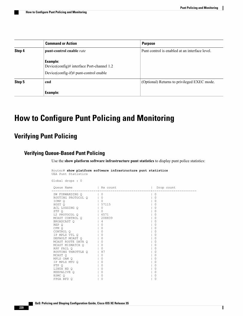
PurposeCommand or Action
Punt control is enabled at an interface level.punt-control enable rate
Example:
Step 4
Device(config)# interface Port-channel 1.2
Device(config-if)# punt-control enable
(Optional) Returns to privileged EXEC mode.end
Example:
Step 5
How to Configure Punt Policing and Monitoring
Verifying Punt Policing
Verifying Queue-Based Punt PolicingUse the show platform software infrastructure punt statistics to display punt police statistics:
Router# show platform software infrastructure punt statisticsUEA Punt Statistics
Global drops : 0
Queue Name | Rx count | Drop count------------------------+---------------------------+-----------------------SW FORWARDING Q | 0 | 0ROUTING PROTOCOL Q | 0 | 0ICMP Q | 0 | 0HOST Q | 57115 | 0ACL LOGGING Q | 0 | 0STP Q | 0 | 0L2 PROTOCOL Q | 6571 | 0MCAST CONTROL Q | 208839 | 0BROADCAST Q | 4 | 0REP Q | 0 | 0CFM Q | 0 | 0CONTROL Q | 0 | 0IP MPLS TTL Q | 0 | 0DEFAULT MCAST Q | 0 | 0MCAST ROUTE DATA Q | 0 | 0MCAST MISMATCH Q | 0 | 0RPF FAIL Q | 0 | 0ROUTING THROTTLE Q | 87 | 0MCAST Q | 0 | 0MPLS OAM Q | 0 | 0IP MPLS MTU Q | 0 | 0PTP Q | 0 | 0LINUX ND Q | 0 | 0KEEPALIVE Q | 0 | 0ESMC Q | 0 | 0FPGA BFD Q | 0 | 0
QoS: Policing and Shaping Configuration Guide, Cisco IOS XE Release 3S220
Punt Policing and MonitoringHow to Configure Punt Policing and Monitoring
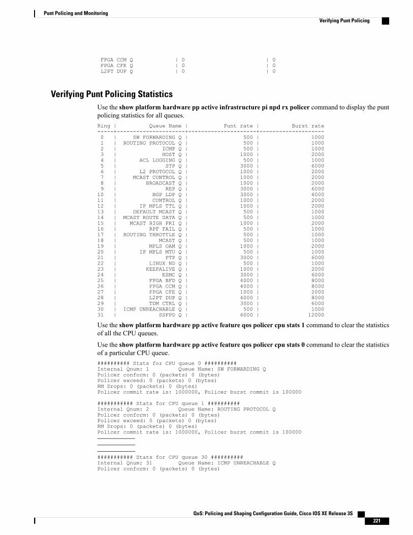
FPGA CCM Q | 0 | 0FPGA CFE Q | 0 | 0L2PT DUP Q | 0 | 0
Verifying Punt Policing StatisticsUse the show platform hardware pp active infrastructure pi npd rx policer command to display the puntpolicing statistics for all queues.Ring | Queue Name | Punt rate | Burst rate-----+---------------------+---------------------+--------------------0 | SW FORWARDING Q | 500 | 10001 | ROUTING PROTOCOL Q | 500 | 10002 | ICMP Q | 500 | 10003 | HOST Q | 1000 | 20004 | ACL LOGGING Q | 500 | 10005 | STP Q | 3000 | 60006 | L2 PROTOCOL Q | 1000 | 20007 | MCAST CONTROL Q | 1000 | 20008 | BROADCAST Q | 1000 | 20009 | REP Q | 3000 | 600010 | BGP LDP Q | 3000 | 600011 | CONTROL Q | 1000 | 200012 | IP MPLS TTL Q | 1000 | 200013 | DEFAULT MCAST Q | 500 | 100014 | MCAST ROUTE DATA Q | 500 | 100015 | MCAST HIGH PRI Q | 1000 | 200016 | RPF FAIL Q | 500 | 100017 | ROUTING THROTTLE Q | 500 | 100018 | MCAST Q | 500 | 100019 | MPLS OAM Q | 1000 | 200020 | IP MPLS MTU Q | 500 | 100021 | PTP Q | 3000 | 600022 | LINUX ND Q | 500 | 100023 | KEEPALIVE Q | 1000 | 200024 | ESMC Q | 3000 | 600025 | FPGA BFD Q | 4000 | 800026 | FPGA CCM Q | 4000 | 800027 | FPGA CFE Q | 1000 | 200028 | L2PT DUP Q | 4000 | 800029 | TDM CTRL Q | 3000 | 600030 | ICMP UNREACHABLE Q | 500 | 100031 | SSFPD Q | 6000 | 12000
Use the show platform hardware pp active feature qos policer cpu stats 1 command to clear the statisticsof all the CPU queues.
Use the show platform hardware pp active feature qos policer cpu stats 0 command to clear the statisticsof a particular CPU queue.########## Stats for CPU queue 0 ##########Internal Qnum: 1 Queue Name: SW FORWARDING QPolicer conform: 0 (packets) 0 (bytes)Policer exceed: 0 (packets) 0 (bytes)RM Drops: 0 (packets) 0 (bytes)Policer commit rate is: 1000000, Policer burst commit is 100000
########### Stats for CPU queue 1 ##########Internal Qnum: 2 Queue Name: ROUTING PROTOCOL QPolicer conform: 0 (packets) 0 (bytes)Policer exceed: 0 (packets) 0 (bytes)RM Drops: 0 (packets) 0 (bytes)Policer commit rate is: 1000000, Policer burst commit is 100000—————————————————————########### Stats for CPU queue 30 ##########Internal Qnum: 31 Queue Name: ICMP UNREACHABLE QPolicer conform: 0 (packets) 0 (bytes)
QoS: Policing and Shaping Configuration Guide, Cisco IOS XE Release 3S 221
Punt Policing and MonitoringVerifying Punt Policing
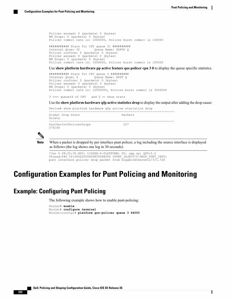
Policer exceed: 0 (packets) 0 (bytes)RM Drops: 0 (packets) 0 (bytes)Policer commit rate is: 1000000, Policer burst commit is 100000
########### Stats for CPU queue 31 ##########Internal Qnum: 32 Queue Name: SSFPD QPolicer conform: 0 (packets) 0 (bytes)Policer exceed: 0 (packets) 0 (bytes)RM Drops: 0 (packets) 0 (bytes)Policer commit rate is: 1000000, Policer burst commit is 100000
Use show platform hardware pp active feature qos policer cpu 3 0 to display the queue specific statistics.########### Stats for CPU queue 3 ##########Internal Qnum: 4 Queue Name: HOST QPolicer conform: 0 (packets) 0 (bytes)Policer exceed: 0 (packets) 0 (bytes)RM Drops: 0 (packets) 0 (bytes)Policer commit rate is: 12000000, Policer burst commit is 3000000
3 —— queueId of CPU and 0 — show stats
Use the show platform hardware qfp active statistics drop to display the output after adding the drop cause:Device# show platform hardware qfp active statistics drop---------------------------------------------------------------------Global Drop Stats PacketsOctets---------------------------------------------------------------------PuntPerIntfPolicerDrops 257274166
When a packet is dropped by per interface punt policer, a log including the source interface is displayedas follows (the log shows one log in 30 seconds):
Note
*Jun 6 08:25:35.893: %IOSXE-5-PLATFORM: F0: cpp_cp: QFP:0.0Thread:046 TS:00000000400859588264 %PUNT_INJECT-5-DROP_PUNT_INTF:punt interface policer drop packet from GigabitEthernet2/3/1.726
Configuration Examples for Punt Policing and Monitoring
Example: Configuring Punt PolicingThe following example shows how to enable punt-policing:Router# enableRouter# configure terminalRouter(config)# platform qos-policer queue 3 64000
QoS: Policing and Shaping Configuration Guide, Cisco IOS XE Release 3S222
Punt Policing and MonitoringConfiguration Examples for Punt Policing and Monitoring

Additional ReferencesRelated Documents
Document TitleRelated Topic
Cisco IOS Quality of Service Solutions CommandReference
QoS commands: complete command syntax,command modes, command history, defaults, usageguidelines, and examples
“Marking Network Traffic” moduleTraffic marking
“Traffic Policing” moduleTraffic policing
“Policing and Shaping Overview” moduleTraffic policing and shaping concepts and overviewinformation
“Applying QoS Features Using the MQC” moduleModular quality of service command-line interface(MQC)
Standards
TitleStandard
—None
MIBs
MIBs LinkMIB
To locate and downloadMIBs for selected platforms,Cisco IOSXE Software releases, and feature sets, useCisco MIB Locator found at the following URL:
http://www.cisco.com/go/mibs
None
RFCs
TitleRFC
None
QoS: Policing and Shaping Configuration Guide, Cisco IOS XE Release 3S 223
Punt Policing and MonitoringAdditional References

Technical Assistance
LinkDescription
http://www.cisco.com/cisco/web/support/index.htmlThe Cisco Support and Documentation websiteprovides online resources to download documentation,software, and tools. Use these resources to install andconfigure the software and to troubleshoot and resolvetechnical issues with Cisco products and technologies.Access to most tools on the Cisco Support andDocumentation website requires a Cisco.com user IDand password.
Feature Information for Punt Policing and MonitoringThe following table provides release information about the feature or features described in this module. Thistable lists only the software release that introduced support for a given feature in a given software releasetrain. Unless noted otherwise, subsequent releases of that software release train also support that feature.
Use Cisco Feature Navigator to find information about platform support and Cisco software image support.To access Cisco Feature Navigator, go to www.cisco.com/go/cfn. An account on Cisco.com is not required.
Table 24: Feature Information for Punt Policing and Monitoring
Feature InformationReleasesFeature Name
The Punt Policing and Monitoringfeature allows you to specify amaximum punt rate on a per-queuebasis.
For Cisco IOS XE Release 3.5S,this feature was implemented onCisco ASR 903 Router.
The following command wasintroduced: platform punt-policequeue
Cisco IOS XE Release 3.5SPunt Policing and Monitoring
QoS: Policing and Shaping Configuration Guide, Cisco IOS XE Release 3S224
Punt Policing and MonitoringFeature Information for Punt Policing and Monitoring

C H A P T E R 20Port-Shaper and LLQ in the Presence of EFPs
The Port-Shaper and LLQ in the Presence of EFPs feature allows network designers to configure port andclass policies on ports that contain Ethernet Flow Points (EFPs). These policies support LowLatencyQueueing(LLQ) and traffic prioritization across the EFPs.
• Finding Feature Information, page 225
• Restrictions for Port-Shaper and LLQ in the Presence of EFPs, page 225
• Information About Port-Shaper and LLQ in the Presence of EFPs, page 226
• How to Configure Port-Shaper and LLQ in the Presence of EFPs, page 226
• Configuration Examples for Port-Shaper and LLQ in the Presence of EFPs, page 233
• Additional References, page 234
• Feature Information for Port-Shaper and LLQ in the Presence of EFPs, page 235
Finding Feature InformationYour software release may not support all the features documented in this module. For the latest caveats andfeature information, see Bug Search Tool and the release notes for your platform and software release. Tofind information about the features documented in this module, and to see a list of the releases in which eachfeature is supported, see the feature information table at the end of this module.
Use Cisco Feature Navigator to find information about platform support and Cisco software image support.To access Cisco Feature Navigator, go to www.cisco.com/go/cfn. An account on Cisco.com is not required.
Restrictions for Port-Shaper and LLQ in the Presence of EFPs• If you configure a class-based policy on the port, then you cannot configure service-policies on EthernetFlow Points (EFPs).
• Attaching a service policy to the BDI is not supported.
• ACL based shaping policy-map cannot be applied to the EFP and/or egress interface.
QoS: Policing and Shaping Configuration Guide, Cisco IOS XE Release 3S 225

Information About Port-Shaper and LLQ in the Presence of EFPs
Ethernet Flow Points and LLQAn Ethernet Flow Point (EFP) is a forwarding decision point in the provider edge (PE) router, which givesnetwork designers flexibility to make many Layer 2 flow decisions within the interface. Many EFPs can beconfigured on a single physical port. (The number varies from one device to another.) EFPs are the logicaldemarcation points of an Ethernet virtual connection (EVC) on an interface. An EVC that uses two or moreUser-Network Interfaces (UNIs) requires an EFP on the associated ingress and egress interfaces of everydevice that the EVC passes through.
The Egress HQoS with Port Level Shaping feature allows network designers to configure port and classpolicies on ports that contain EFPs. These policies support Low Latency Queueing (LLQ) and trafficprioritization across the EFPs.
For information on how to configure LLQ, see the QoS Congestion Management Configuration Guide.
How to Configure Port-Shaper and LLQ in the Presence of EFPsTo configure the Port-Shaper and LLQ in the Presence of EFPs feature, you first create either a hierarchicalor flat policy map that supports Low Latency Queueing (LLQ), which you then attach to an EFP interface.
Configuring Hierarchical Policy MapsTo configure hierarchical policy maps, you create child policies which you then attach to a parent policy. Theparent policy is then attached to an interface.
SUMMARY STEPS
1. enable2. configure terminal3. policy-map policy-map-name4. class class-map-name5. set cos value6. bandwidth percent percent7. exit8. class class-map-name9. bandwidth percent percent10. exit11. policy-map policy-map-name12. class class-default13. service-policy policy-map-name
QoS: Policing and Shaping Configuration Guide, Cisco IOS XE Release 3S226
Port-Shaper and LLQ in the Presence of EFPsInformation About Port-Shaper and LLQ in the Presence of EFPs
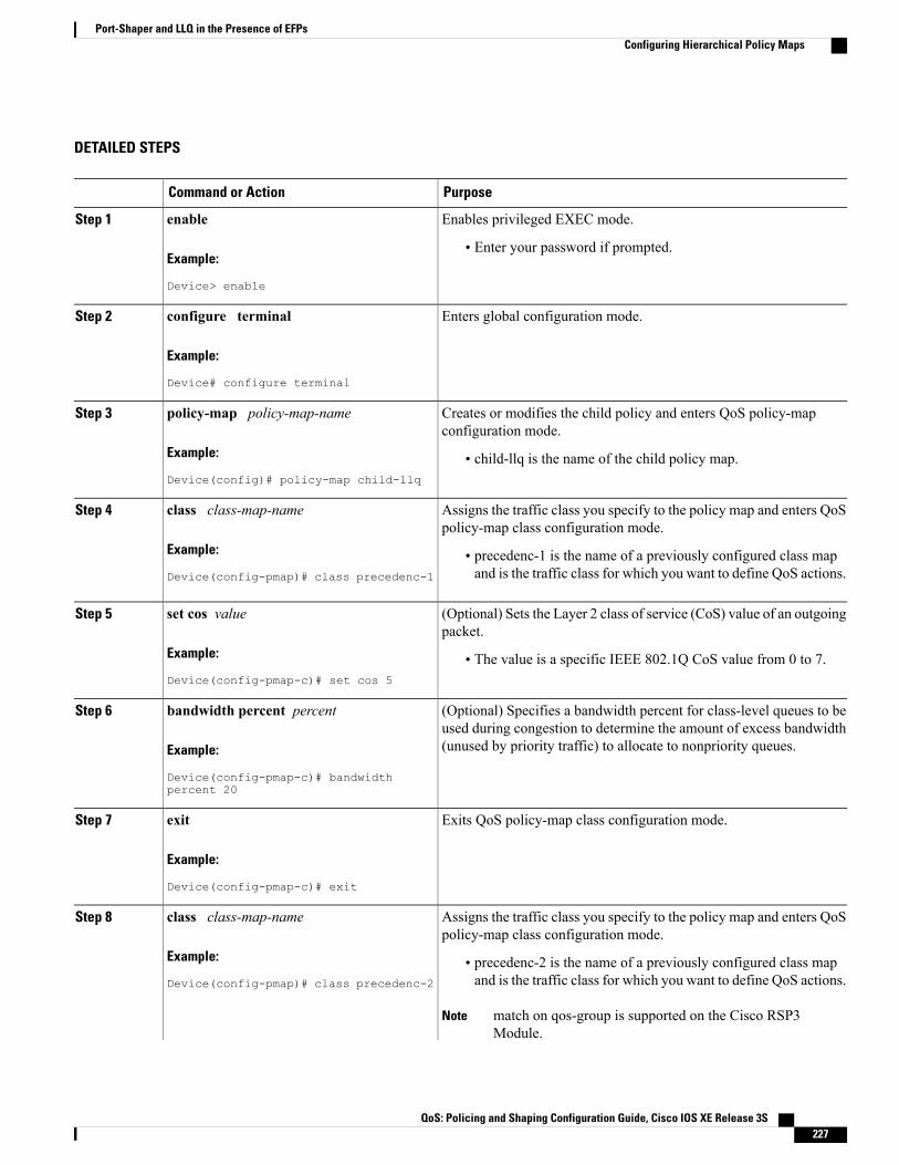
DETAILED STEPS
PurposeCommand or Action
Enables privileged EXEC mode.enableStep 1
Example:
Device> enable
• Enter your password if prompted.
Enters global configuration mode.configure terminal
Example:
Device# configure terminal
Step 2
Creates or modifies the child policy and enters QoS policy-mapconfiguration mode.
policy-map policy-map-name
Example:
Device(config)# policy-map child-llq
Step 3
• child-llq is the name of the child policy map.
Assigns the traffic class you specify to the policy map and enters QoSpolicy-map class configuration mode.
class class-map-name
Example:
Device(config-pmap)# class precedenc-1
Step 4
• precedenc-1 is the name of a previously configured class mapand is the traffic class for which you want to define QoS actions.
(Optional) Sets the Layer 2 class of service (CoS) value of an outgoingpacket.
set cos value
Example:
Device(config-pmap-c)# set cos 5
Step 5
• The value is a specific IEEE 802.1Q CoS value from 0 to 7.
(Optional) Specifies a bandwidth percent for class-level queues to beused during congestion to determine the amount of excess bandwidth(unused by priority traffic) to allocate to nonpriority queues.
bandwidth percent percent
Example:
Device(config-pmap-c)# bandwidthpercent 20
Step 6
Exits QoS policy-map class configuration mode.exit
Example:
Device(config-pmap-c)# exit
Step 7
Assigns the traffic class you specify to the policy map and enters QoSpolicy-map class configuration mode.
class class-map-name
Example:
Device(config-pmap)# class precedenc-2
Step 8
• precedenc-2 is the name of a previously configured class mapand is the traffic class for which you want to define QoS actions.
match on qos-group is supported on the Cisco RSP3Module.
Note
QoS: Policing and Shaping Configuration Guide, Cisco IOS XE Release 3S 227
Port-Shaper and LLQ in the Presence of EFPsConfiguring Hierarchical Policy Maps
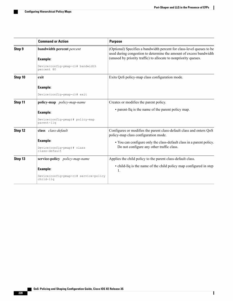
PurposeCommand or Action
(Optional) Specifies a bandwidth percent for class-level queues to beused during congestion to determine the amount of excess bandwidth(unused by priority traffic) to allocate to nonpriority queues.
bandwidth percent percent
Example:
Device(config-pmap-c)# bandwidthpercent 80
Step 9
Exits QoS policy-map class configuration mode.exit
Example:
Device(config-pmap-c)# exit
Step 10
Creates or modifies the parent policy.policy-map policy-map-nameStep 11
Example:
Device(config-pmap)# policy-mapparent-llq
• parent-llq is the name of the parent policy map.
Configures or modifies the parent class-default class and enters QoSpolicy-map class configuration mode.
class class-default
Example:
Device(config-pmap)# classclass-default
Step 12
• You can configure only the class-default class in a parent policy.Do not configure any other traffic class.
Applies the child policy to the parent class-default class.service-policy policy-map-nameStep 13
Example:
Device(config-pmap-c)# service-policychild-llq
• child-llq is the name of the child policy map configured in step1.
QoS: Policing and Shaping Configuration Guide, Cisco IOS XE Release 3S228
Port-Shaper and LLQ in the Presence of EFPsConfiguring Hierarchical Policy Maps
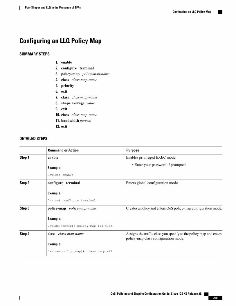
Configuring an LLQ Policy Map
SUMMARY STEPS
1. enable2. configure terminal3. policy-map policy-map-name4. class class-map-name5. priority6. exit7. class class-map-name8. shape average value9. exit10. class class-map-name11. bandwidth percent12. exit
DETAILED STEPS
PurposeCommand or Action
Enables privileged EXEC mode.enableStep 1
Example:
Device> enable
• Enter your password if prompted.
Enters global configuration mode.configure terminal
Example:
Device# configure terminal
Step 2
Creates a policy and enters QoS policy-map configurationmode.policy-map policy-map-name
Example:
Device(config)# policy-map llq-flat
Step 3
Assigns the traffic class you specify to the policy map and enterspolicy-map class configuration mode.
class class-map-name
Example:
Device(config-pmap)# class dscp-af1
Step 4
QoS: Policing and Shaping Configuration Guide, Cisco IOS XE Release 3S 229
Port-Shaper and LLQ in the Presence of EFPsConfiguring an LLQ Policy Map

PurposeCommand or Action
Configures LLQ, providing strict priority queueing (PQ) forclass-based weighted fair queueing (CBWFQ).
priority
Example:
Device(config-pmap-c)# priority
Step 5
Exits QoS policy-map class configuration mode.exit
Example:
Device(config-pmap-c)# exit
Step 6
Assigns the traffic class you specify to the policy map and entersQoS policy-map class configuration mode.
class class-map-name
Example:
Device(config-pmap)# class dscp-af2
Step 7
Configures a shape entity with a Comitted Information Rate of200 Mb/s.
shape average value
Example:
Device(config-pmap-c)# shape average200000000
Step 8
Exits QoS policy-map class configuration mode.exit
Example:
Device(config-pmap-c)# exit
Step 9
Assigns the traffic class you specify to the policy map and entersQoS policy-map class configuration mode.
class class-map-name
Example:
Device(config-pmap)# class dscp-af3
Step 10
(Optional) Specifies a bandwidth percent for class-level queuesto be used during congestion to determine the amount of excess
bandwidth percent
Example:
Device(config-pmap-c)# bandwidth 4000000
Step 11
bandwidth (unused by priority traffic) to allocate to non-priorityqueues.
Exits QoS policy-map class configuration mode.exit
Example:
Device(config-pmap-c)# exit
Step 12
QoS: Policing and Shaping Configuration Guide, Cisco IOS XE Release 3S230
Port-Shaper and LLQ in the Presence of EFPsConfiguring an LLQ Policy Map
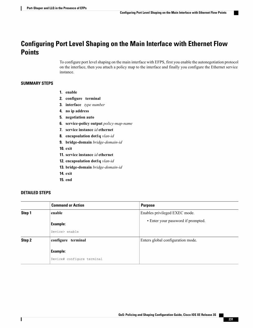
Configuring Port Level Shaping on the Main Interface with Ethernet FlowPoints
To configure port level shaping on the main interface with EFPS, first you enable the autonegotiation protocolon the interface, then you attach a policy map to the interface and finally you configure the Ethernet serviceinstance.
SUMMARY STEPS
1. enable2. configure terminal3. interface type number4. no ip address5. negotiation auto6. service-policy output policy-map-name7. service instance id ethernet8. encapsulation dot1q vlan-id9. bridge-domain bridge-domain-id10. exit11. service instance id ethernet12. encapsulation dot1q vlan-id13. bridge-domain bridge-domain-id14. exit15. end
DETAILED STEPS
PurposeCommand or Action
Enables privileged EXEC mode.enableStep 1
Example:
Device> enable
• Enter your password if prompted.
Enters global configuration mode.configure terminal
Example:
Device# configure terminal
Step 2
QoS: Policing and Shaping Configuration Guide, Cisco IOS XE Release 3S 231
Port-Shaper and LLQ in the Presence of EFPsConfiguring Port Level Shaping on the Main Interface with Ethernet Flow Points

PurposeCommand or Action
Configures an interface type and enters interfaceconfiguration mode.
interface type number
Example:
Device(config)# interface GigabitEthernet0/0/1
Step 3
• Enter the interface type number.
Disables IP routing on the interface.no ip address
Example:
Device(config-if)# no ip address
Step 4
Enables the autonegotiation protocol to configure the speed,duplex, and automatic flow control of the Gigabit Ethernetinterface.
negotiation auto
Example:
Device(config-if)# negotiation auto
Step 5
Specifies the name of the policy map to be attached to theinput or output direction of the interface.
service-policy output policy-map-name
Example:
Device(config-if)# service-policy outputparent-llq
Step 6
• You can enter the name of a hierarchical or a flat policymap.
Configures an Ethernet service instance on an interface andenters service instance configuration mode.
service instance id ethernet
Example:
Device(config-if)# service instance 1 ethernet
Step 7
Defines the matching criteria to map 802.1Q frames' ingresson an interface to the service instance.
encapsulation dot1q vlan-id
Example:
Device(config-if-srv)# encapsulation dot1q100
Step 8
Binds the bridge domain to the service instance.bridge-domain bridge-domain-id
Example:
Device(config-if-srv)# bridge-domain 100
Step 9
Exits service instance configuration mode.exit
Example:
Device(config-if-serv)# exit
Step 10
QoS: Policing and Shaping Configuration Guide, Cisco IOS XE Release 3S232
Port-Shaper and LLQ in the Presence of EFPsConfiguring Port Level Shaping on the Main Interface with Ethernet Flow Points

PurposeCommand or Action
Configures an Ethernet service instance on an interface andenters service instance configuration mode.
service instance id ethernet
Example:
Device(config-if)# service instance 2 ethernet
Step 11
Defines the matching criteria to map 802.1Q frames' ingresson an interface to the service instance.
encapsulation dot1q vlan-id
Example:
Device(config-if-srv)# encapsulation dot1q101
Step 12
Binds the bridge domain to the service instance.bridge-domain bridge-domain-id
Example:
Device(config-if-srv)# bridge-domain 101
Step 13
Exits QoS policy-map class configuration mode.exit
Example:
Device(config-if-srv)# exit
Step 14
(Optional) Exits interface configuration mode.end
Example:
Device(config-if)# end
Step 15
Configuration Examples for Port-Shaper and LLQ in the Presenceof EFPs
Example: Configuring Hierarchical QoS Port Level Shaping on the MainInterface with EFPs
The following example shows how to configure hierarchical QoS port level shaping on a main physicalinterface to support traffic prioritization and Low Level Queueing across all EFPs configured on the interface:
policy-map parent-llqclass class-defaultservice-policy child-llq
policy-map child-llq
QoS: Policing and Shaping Configuration Guide, Cisco IOS XE Release 3S 233
Port-Shaper and LLQ in the Presence of EFPsConfiguration Examples for Port-Shaper and LLQ in the Presence of EFPs

class precedenc-1set cos 5bandwidth percent 20class precedenc-2bandwidth percent 80
interface GigabitEthernet 0/0/1no ip addressnegotiation autoservice-policy output parent-llqservice instance 1 ethernetencapsulation dot1q 100bridge-domain 100!service instance 2 ethernetencapsulation dot1q 101bridge-domain 101
Example: Configuring Port Level Shaping on the Main Interface with EFPsThe following example shows how to configure port level shaping on a main physical interface to supporttraffic prioritization and Low Level Queueing across all Ethernet Flow Points (EFPs) configured on theinterface:policy-map llq_flatclass dscp-af1priorityclass dscp-af2shape average 200000000class dscp-af3bandwidth 400000
interface GigabitEthernet 0/0/1no ip addressnegotiation autoservice-policy output class_policy_claservice instance 1 ethernetencapsulation dot1q 100bridge-domain 100!service instance 2 ethernetencapsulation dot1q 101bridge-domain 101
Additional ReferencesRelated Documents
Document TitleRelated Topic
Cisco IOS Master Commands List, All ReleasesCisco IOS commands
Cisco IOS QoS Command ReferenceQoS commands: complete command syntax,command modes, command history, defaults, usageguidelines, and examples
"Policing and Shaping Overview" modulePolicing and shaping
QoS: Policing and Shaping Configuration Guide, Cisco IOS XE Release 3S234
Port-Shaper and LLQ in the Presence of EFPsExample: Configuring Port Level Shaping on the Main Interface with EFPs
Document TitleRelated Topic
"Applying QoS Features Using the MQC" moduleClass maps
"Applying QoS Features Using the MQC" modulePolicy maps
QoS Congestion Management Configuration GuideLow Latency Queueing
Standards and RFCs
TitleStandard
--No new or modified standards are supported, andsupport for existing standards has not been modified.
MIBs
MIBs LinkMIB
To locate and downloadMIBs for selected platforms,Cisco IOSXE software releases, and feature sets, useCisco MIB Locator found at the following URL:
http://www.cisco.com/go/mibs
No new or modifiedMIBs are supported, and supportfor existing MIBs has not been modified.
Technical Assistance
LinkDescription
http://www.cisco.com/cisco/web/support/index.htmlThe Cisco Support and Documentation websiteprovides online resources to download documentation,software, and tools. Use these resources to install andconfigure the software and to troubleshoot and resolvetechnical issues with Cisco products and technologies.Access to most tools on the Cisco Support andDocumentation website requires a Cisco.com user IDand password.
Feature Information for Port-Shaper and LLQ in the Presence ofEFPs
The following table provides release information about the feature or features described in this module. Thistable lists only the software release that introduced support for a given feature in a given software releasetrain. Unless noted otherwise, subsequent releases of that software release train also support that feature.
QoS: Policing and Shaping Configuration Guide, Cisco IOS XE Release 3S 235
Port-Shaper and LLQ in the Presence of EFPsFeature Information for Port-Shaper and LLQ in the Presence of EFPs
Use Cisco Feature Navigator to find information about platform support and Cisco software image support.To access Cisco Feature Navigator, go to www.cisco.com/go/cfn. An account on Cisco.com is not required.
Table 25: Feature Information for Port-Shaper and LLQ in the Presence of EFPs
Feature InformationReleasesFeature Name
The Port-Shaper and LLQ in thePresence of EFPs feature providessupport for LLQ and trafficprioritization across all EFPs on aport.
In Cisco IOS XE Release 3.6S,support was added for the CiscoASR 903 router.
Cisco IOS Release XE 3.6SPort-Shaper and LLQ in thePresence of EFPs
QoS: Policing and Shaping Configuration Guide, Cisco IOS XE Release 3S236
Port-Shaper and LLQ in the Presence of EFPsFeature Information for Port-Shaper and LLQ in the Presence of EFPs
C H A P T E R 21Adaptive QoS over DMVPN
Adaptive QoS over Dynamic Multipoint VPN (DMVPN) ensures effective bandwidth management usingdynamic shapers based on available bandwidth. This feature enables various QoS features to adapt to nonservice-level agreement (SLA) based environments where bandwidth is variable and fluctuate with time.
• Finding Feature Information, page 237
• Prerequisites for Adaptive QoS over DMVPN, page 237
• Restrictions for Adaptive QoS over DMVPN, page 238
• Information About Adaptive QoS over DMVPN, page 238
• How to Configure Adaptive QoS over DMVPN, page 240
• Configuration Examples for Configuring Adaptive QoS over DMVPN, page 244
• Additional References, page 247
• Feature Information for Adaptive QoS over DMVPN , page 248
Finding Feature InformationYour software release may not support all the features documented in this module. For the latest caveats andfeature information, see Bug Search Tool and the release notes for your platform and software release. Tofind information about the features documented in this module, and to see a list of the releases in which eachfeature is supported, see the feature information table at the end of this module.
Use Cisco Feature Navigator to find information about platform support and Cisco software image support.To access Cisco Feature Navigator, go to www.cisco.com/go/cfn. An account on Cisco.com is not required.
Prerequisites for Adaptive QoS over DMVPNAdaptive QoS over DMVPN can be enabled either on hub or spoke or both. To enable feature at a spoke side,the spoke must support basic egress per-SA QoS policy.
Internet Protocol Security (IPSec) is required and must be configured before Adaptive QoS is enabled on theDMVPN tunnel.
QoS: Policing and Shaping Configuration Guide, Cisco IOS XE Release 3S 237
Restrictions for Adaptive QoS over DMVPNThe Adaptive QoS over DMVPN feature configuration is:
• Supported only on DMVPN tunnels
• Allowed only on egress direction
• Allowed only in parent most policy that has class-default only
• Not supported on Point-to-Point tunnels
Information About Adaptive QoS over DMVPN
Overview of Adaptive QoS over DMVPNEnterprise networks are increasingly using the Internet as form of WAN transport, therefore QoS modelsneeds to be revisited. QoSworks effectively when deployed in an service-level agreement (SLA) environmenttoday, like Multiprotocol Label Switching (MPLS) . The available bandwidth on the internet at a given pointof time can vary, and can be often much lesser than the actual bandwidth offered by the service provider. Incases of non SLA environments, QoS has limitations - mainly because it cannot predict changing bandwidthon the link.
Cisco Intelligent WAN (IWAN) recommends using Dynamic Multipoint VPN (DMVPN) over Internet toconnect branches to the data center or headquarters, and QoS to be deployed in such environments of fluctuatingbandwidth. Currently, the shapers that are applied as part of the egress QoS policy are static in value - theyare configured based on the service provider bandwidth offering, they do not change with time and hence donot reflect the actual available Internet bandwidth. In many instances where Internet available bandwidthbecomes much lesser than the offered bandwidth, the shapers become irrelevant as they do not adapt to thevarying bandwidth. Due to the static value of the shapers, application traffic gets dropped indiscriminately atthe Internet core, nullifying the very need to have configured a QoS policy to protect critical traffic.
DMVPN provides the ability to do QoS per-tunnel, which means a QoS policy can be applied at the hubtowards a specific spoke, to ensure a high bandwidth hub does not overrun a low capacity spoke. However,these QoS policies still work with static shapers per spoke. If the bandwidth towards a particular spokefluctuates, the shapers towards the spokes do not adapt. Also, it is not possible today to configure a QoS policyfor the traffic from the spoke towards the hub, which is very common in many retail-like environments.
The Adaptive QoS over DMVPN feature provides the following benefits:
• Adjusts the shaper parameters based on the actual available Internet bandwidth in both directions thatis periodically computed.
• Allows to configure a QoS policy on the spoke towards the hub.
• Ensures better control of application performance at the enterprise edge even in changing bandwidthscenarios over the Internet.
• Allows aggregate tunnel shape adaptation to provide effective bandwidth between spoke and hub.
QoS: Policing and Shaping Configuration Guide, Cisco IOS XE Release 3S238
Adaptive QoS over DMVPNRestrictions for Adaptive QoS over DMVPN
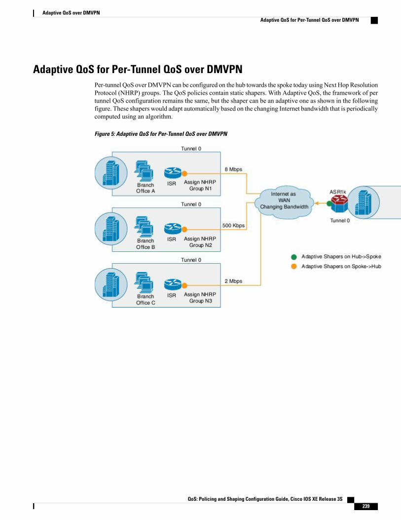
Adaptive QoS for Per-Tunnel QoS over DMVPNPer-tunnel QoS over DMVPN can be configured on the hub towards the spoke today usingNext Hop ResolutionProtocol (NHRP) groups. The QoS policies contain static shapers. With Adaptive QoS, the framework of pertunnel QoS configuration remains the same, but the shaper can be an adaptive one as shown in the followingfigure. These shapers would adapt automatically based on the changing Internet bandwidth that is periodicallycomputed using an algorithm.
Figure 5: Adaptive QoS for Per-Tunnel QoS over DMVPN
QoS: Policing and Shaping Configuration Guide, Cisco IOS XE Release 3S 239
Adaptive QoS over DMVPNAdaptive QoS for Per-Tunnel QoS over DMVPN
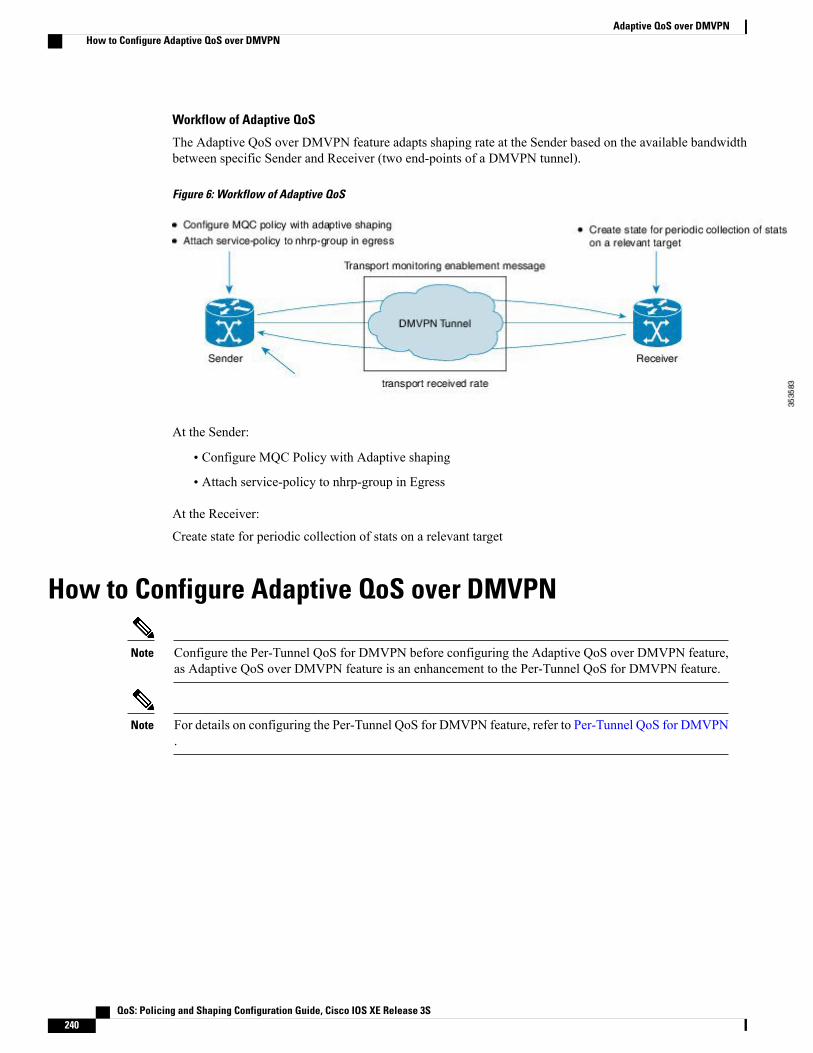
Workflow of Adaptive QoS
The Adaptive QoS over DMVPN feature adapts shaping rate at the Sender based on the available bandwidthbetween specific Sender and Receiver (two end-points of a DMVPN tunnel).
Figure 6: Workflow of Adaptive QoS
At the Sender:
• Configure MQC Policy with Adaptive shaping
• Attach service-policy to nhrp-group in Egress
At the Receiver:
Create state for periodic collection of stats on a relevant target
How to Configure Adaptive QoS over DMVPN
Configure the Per-Tunnel QoS for DMVPN before configuring the Adaptive QoS over DMVPN feature,as Adaptive QoS over DMVPN feature is an enhancement to the Per-Tunnel QoS for DMVPN feature.
Note
For details on configuring the Per-Tunnel QoS for DMVPN feature, refer to Per-Tunnel QoS for DMVPN.
Note
QoS: Policing and Shaping Configuration Guide, Cisco IOS XE Release 3S240
Adaptive QoS over DMVPNHow to Configure Adaptive QoS over DMVPN

Configuring Adaptive QoS for DMVPN
SUMMARY STEPS
1. enable2. configure terminal3. policy-map parent-policy-name4. class class-default5. shape adaptive { upper-bound bps |percent percentage }[lower-bound bps| percent percentage]6. end7. configure terminal8. interface tunnel tunnel-id9. nhrp map group group-name service-policy output parent-policy-name10. end
DETAILED STEPS
PurposeCommand or Action
Enables privileged EXEC mode.enableStep 1
Example:
Router> enable
• Enter your password if prompted.
Enters global configuration mode.configure terminal
Example:
Router# configure terminal
Step 2
Creates or modifies a child policy map and enters policy-mapconfiguration mode.
policy-map parent-policy-name
Example:
Router(config)# policy-map example
Step 3
• Enter the name of the child policy map.
This step associates the traffic class with the traffic policy.Configures the default class map and enters policy-map classconfiguration mode.
class class-default
Example:
Router(config-pmap)# class class-default
Step 4
Creates a specific adaptive shaper that has upper bound onthe rate and optionally lower bound on the rate.
shape adaptive { upper-bound bps |percentpercentage }[lower-bound bps| percent percentage]
Step 5
QoS: Policing and Shaping Configuration Guide, Cisco IOS XE Release 3S 241
Adaptive QoS over DMVPNConfiguring Adaptive QoS for DMVPN
PurposeCommand or Action
Example:
Router(config-pmap-c)# shape adaptiveupper-bound 20000
When such a template is attached to a target, adaptiveshaping is enabled for that instance. Shaping rateadapts to a new rate, that is a function of parameters,including peer's received rate.
Note
Returns to privileged EXEC mode.end
Example:
Router(config-pmap-c)# end
Step 6
Enters global configuration mode.configure terminal
Example:
Router# configure terminal
Step 7
Configures an interface type and enters interface configurationmode.
interface tunnel tunnel-id
Example:
Router(config)# interface tunnel 0
Step 8
• Enter the interface type and interface number.
Adds the NHRP group to the QoS policy map on the hub.nhrpmap group group-name service-policy outputparent-policy-name
Step 9
Example:
Router(config-if)# nhrp map group 1service-policy output example
Returns to privileged EXEC mode.end
Example:
Router(config-if)# end
Step 10
QoS: Policing and Shaping Configuration Guide, Cisco IOS XE Release 3S242
Adaptive QoS over DMVPNConfiguring Adaptive QoS for DMVPN

Verifying the Adaptive QoS over DMVPN
SUMMARY STEPS
1. enable2. show dmvpn3. show policy-map [policy-map-name]4. show policy-map multipoint5. exit
DETAILED STEPS
PurposeCommand or Action
Enables higher privilege levels, such as privileged EXEC mode.enableStep 1
Example:
Router> enable
• Enter your password if prompted.
Displays detailed DMVPN information for each session, including theNext Hop Server (NHS) and NHS status, crypto session information,
show dmvpn
Example:Router# show dmvpn
Step 2
and socket details. Also displays the NHRP group received from thespoke and the QoS policy applied to the spoke tunnel.
Displays the configuration of all classes for a specified policy map orof all classes for all existing policy maps.
show policy-map [policy-map-name]
Example:Router# show policy-map example
Step 3
(Optional) Displays the statistics and the configurations of the inputand output policies that are attached to an interface.
show policy-map multipoint
Example:Router# show policy-map tunnel 0
Step 4
(Optional) Returns to user EXEC mode.exit
Example:
Router(config-if)# exit
Step 5
QoS: Policing and Shaping Configuration Guide, Cisco IOS XE Release 3S 243
Adaptive QoS over DMVPNVerifying the Adaptive QoS over DMVPN
Troubleshooting the Adaptive QoS over DMVPN
SUMMARY STEPS
1. enable2. debug qos peer mon detail3. debug qos peer rate detail
DETAILED STEPS
PurposeCommand or Action
Enables higher privilege levels, such as privileged EXECmode.
enable
Example:
Router> enable
Step 1
• Enter your password if prompted.
Displays debug messages for Adaptive QoS over DMVPN.debug qos peer mon detail
Example:Router# debug qos peer mon detail
Step 2
Displays debug messages for Adaptive QoS over DMVPN.debug qos peer rate detail
Example:Router# debug qos peer rate detail
Step 3
Configuration Examples for Configuring Adaptive QoS overDMVPN
Example Configuring Adaptive QoS over DMVPNThe following example shows how to configure Adaptive QoS over DMVPN:
Router(config)# policy-map exampleRouter(config-pmap)# class class-defaultRouter(config-pmap-c)# shape adaptive upper-bound 20000Router(config-pmap-c)# endRouter# configure terminalRouter(config)# interface tunnel 0Router(config-if)# nhrp map group 1 service-policy output exampleRouter(config-if)# end
QoS: Policing and Shaping Configuration Guide, Cisco IOS XE Release 3S244
Adaptive QoS over DMVPNTroubleshooting the Adaptive QoS over DMVPN

Example Verifying Adaptive QoS over DMVPNThe show policy-map and show policy-map interface commands can be used to confirm that the AdaptiveQoS over DMVPN feature is enabled at an interface.
The following is a sample output of the show dmvpn command:Router# show dmvpn
Interface: Tunnel1, IPv4 NHRP DetailsType: Hub, NHRP Peers:1,
# Ent Peer NBMA Addr Peer Tunnel Add State UpDn Tm Attrb----- ------------- ---------------- ----- ------- -----1 10.1.1.1 10.10.1.2 UP 00:18:37 D
Interface: Tunnel2, IPv4 NHRP DetailsType: Hub, NHRP Peers:1,
# Ent Peer NBMA Addr Peer Tunnel Add State UpDn Tm Attrb----- --------------- -------------- ------ ------- -------
1 10.2.1.1 10.10.2.2 UP 00:22:09 D
Interface: Tunnel3, IPv4 NHRP DetailsType: Hub, NHRP Peers:1,
# Ent Peer NBMA Addr Peer Tunnel Add State UpDn Tm Attrb----- -------------- --------------- ------ ------- ----
1 10.3.1.1 10.10.3.2 UP 00:22:04 D
Interface: Tunnel4, IPv4 NHRP DetailsType: Hub, NHRP Peers:1,
# Ent Peer NBMA Addr Peer Tunnel Add State UpDn Tm Attrb----- -------------- ---------------- ----- ------ ----1 10.3.1.1 10.10.3.2 UP 00:22:01 D
The following is a sample output of the show policy-map command:
Router# show policy-map
Policy Map testClass class-defaultAdaptive Rate Traffic Shapingcir upper-bound 2120000 (bps) cir lower-bound 1120000 (bps)
The following is a sample output of the show policy-map multipoint command:
Router# show policy-map multipoint
Service-policy output: test
Class-map: class-default (match-any)
QoS: Policing and Shaping Configuration Guide, Cisco IOS XE Release 3S 245
Adaptive QoS over DMVPNExample Verifying Adaptive QoS over DMVPN
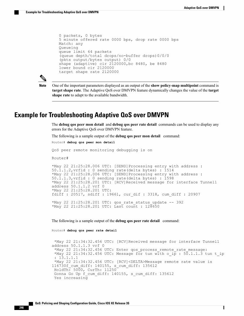
0 packets, 0 bytes5 minute offered rate 0000 bps, drop rate 0000 bpsMatch: anyQueueingqueue limit 64 packets(queue depth/total drops/no-buffer drops)0/0/0(pkts output/bytes output) 0/0shape (adaptive) cir 2120000,bc 8480, be 8480lower bound cir 2120000target shape rate 2120000
One of the important parameters displayed as an output of the show policy-map multipoint command istarget shape rate. The Adaptive QoS over DMVPN feature dynamically changes the value of the targetshape rate to adapt to the available bandwidth.
Note
Example for Troubleshooting Adaptive QoS over DMVPNThe debug qos peer mon detail and debug qos peer rate detail commands can be used to display anyerrors for the Adaptive QoS over DMVPN feature.
The following is a sample output of the debug qos peer mon detail command:Router# debug qos peer mon detail
QoS peer remote monitoring debugging is on
Router#
*May 22 21:25:28.006 UTC: [SEND]Processing entry with address :50.1.1.2,vrfid : 0 sending rate(delta bytes) : 1514*May 22 21:25:28.006 UTC: [SEND]Processing entry with address :50.1.1.3,vrfid : 0 sending rate(delta bytes) : 1598*May 22 21:25:28.201 UTC: [RCV]Received message for interface Tunnel1address 50.1.1.2 vrf 0*May 22 21:25:28.201 UTC:fdiff : 20517, sdiff : 19661, cur_dif : 3318, cum_diff : 20907
*May 22 21:25:28.201 UTC: qos_rate_status_update -- 392*May 22 21:25:28.201 UTC: Last count : 128650
The following is a sample output of the debug qos peer rate detail command:
Router# debug qos peer rate detail
*May 22 21:34:32.456 UTC: [RCV]Received message for interface Tunnel1address 50.1.1.3 vrf 0*May 22 21:34:32.456 UTC: Enter qos_process_remote_rate_message:*May 22 21:34:32.456 UTC: Message for tun with o_ip : 50.1.1.3 tun t_ip: 13.1.1.1*May 22 21:34:32.456 UTC: [RCV]<DELTA>Message remote rate value is116730f_cum_diff: 140155, s_cum_diff: 135612HoldTh: 5000, CurTh: 11250Gonna Go Up f_cum_diff: 140155, s_cum_diff: 135612Yes increasing
QoS: Policing and Shaping Configuration Guide, Cisco IOS XE Release 3S246
Adaptive QoS over DMVPNExample for Troubleshooting Adaptive QoS over DMVPN
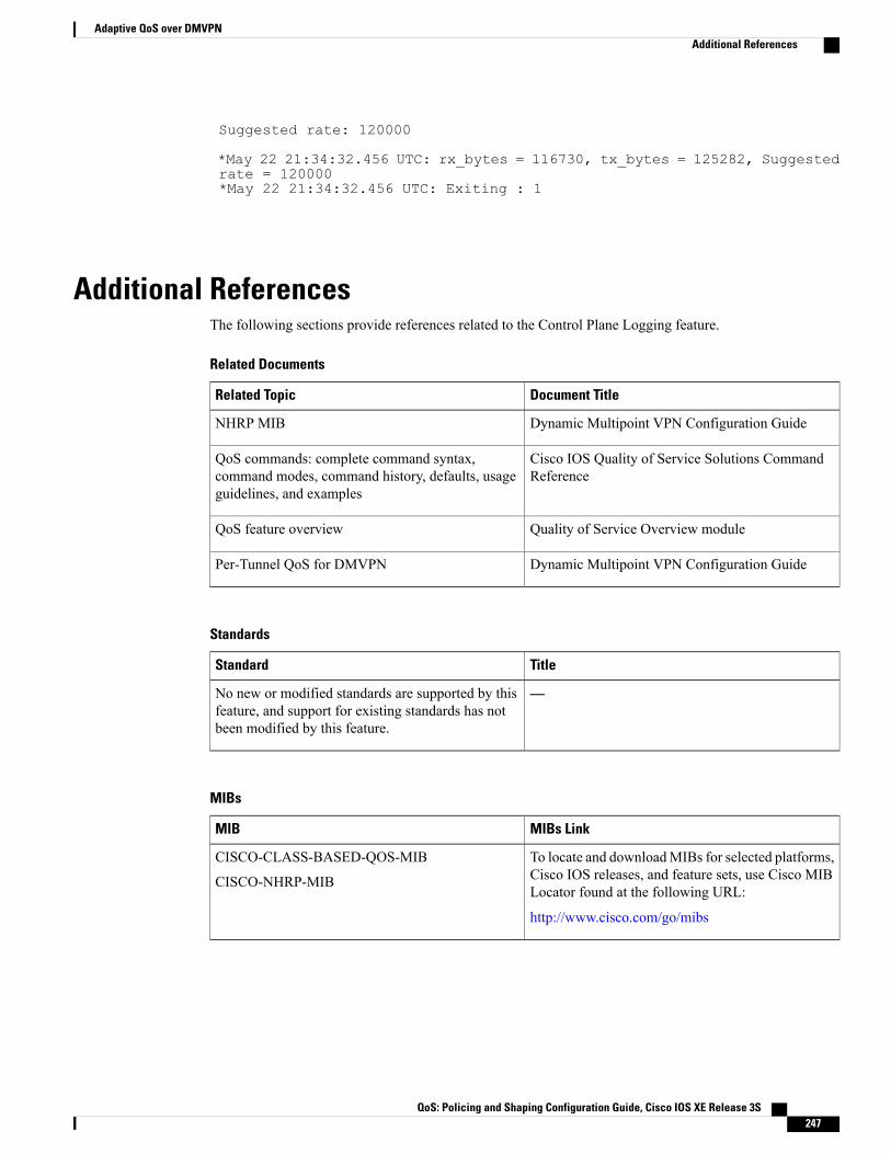
Suggested rate: 120000
*May 22 21:34:32.456 UTC: rx_bytes = 116730, tx_bytes = 125282, Suggestedrate = 120000*May 22 21:34:32.456 UTC: Exiting : 1
Additional ReferencesThe following sections provide references related to the Control Plane Logging feature.
Related Documents
Document TitleRelated Topic
Dynamic Multipoint VPN Configuration GuideNHRP MIB
Cisco IOS Quality of Service Solutions CommandReference
QoS commands: complete command syntax,command modes, command history, defaults, usageguidelines, and examples
Quality of Service Overview moduleQoS feature overview
Dynamic Multipoint VPN Configuration GuidePer-Tunnel QoS for DMVPN
Standards
TitleStandard
—No new or modified standards are supported by thisfeature, and support for existing standards has notbeen modified by this feature.
MIBs
MIBs LinkMIB
To locate and downloadMIBs for selected platforms,Cisco IOS releases, and feature sets, use Cisco MIBLocator found at the following URL:
http://www.cisco.com/go/mibs
CISCO-CLASS-BASED-QOS-MIB
CISCO-NHRP-MIB
QoS: Policing and Shaping Configuration Guide, Cisco IOS XE Release 3S 247
Adaptive QoS over DMVPNAdditional References
RFCs
TitleRFC
—None
Technical Assistance
LinkDescription
http://www.cisco.com/techsupportThe Cisco Technical Support website containsthousands of pages of searchable technical content,including links to products, technologies, solutions,technical tips, and tools. Registered Cisco.com userscan log in from this page to access evenmore content.
Feature Information for Adaptive QoS over DMVPNThe following table provides release information about the feature or features described in this module. Thistable lists only the software release that introduced support for a given feature in a given software releasetrain. Unless noted otherwise, subsequent releases of that software release train also support that feature.
Use Cisco Feature Navigator to find information about platform support and Cisco software image support.To access Cisco Feature Navigator, go to www.cisco.com/go/cfn. An account on Cisco.com is not required.
Table 26: Feature Information for Adaptive QoS over DMVPN
Feature InformationReleasesFeature Name
Adaptive QoS over DynamicMultipointVPN (DMVPN) ensureseffective bandwidth managementusing dynamic shapers based onavailable bandwidth. This featureenables various QoS features toadapt to non service-levelagreement (SLA) basedenvironments where bandwidth isvariable and fluctuate with time.
The following commands wereintroduced or modified: shapeadaptive, show policy-map, andshow policy-map interface.
Cisco IOS XE 3.14SAdaptive QoS over DMVPN
QoS: Policing and Shaping Configuration Guide, Cisco IOS XE Release 3S248
Adaptive QoS over DMVPNFeature Information for Adaptive QoS over DMVPN