qlogic san boot configuration manual - fujitsu · storage area network san world wide name wwn ......
TRANSCRIPT
Copyright 2016 FUJITSU LIMITED CA92344-1120-01
PRIMEQUEST 2000 Series
QLogic Fibre Channel Card
SAN Boot Configuration Manual

Copyright 2016 FUJITSU LIMITED 2 CA92344-1120-01
Introduction
This document describes on configuring of FC SAN Boot with QLogic Fibre Channel Card.
To configure the server, refer the following manuals.
http://www.fujitsu.com/global/products/computing/servers/mission-critical/primequest/documents/manuals/
About this manual - for safe use –
This manual contains information to use this product safely. Before use of this product, read and understand
this manual well.
We pay attention for users to use our products safely without harming neither users, other people, and their
properties. When you use this product, follow the instructions in this manual.
About this product
This product is designed and manufactured as for general use, such as in an office, personal use, household,
and normal industry. Not for applications which are required extremely high safety (hereinafter referred to as
"high-safety applications"), such as nuclear power control, aircraft flight control, air traffic control, mass
transport operation control, life support, and weapons firing control, which involves serious risk against life
unless safety is ensured.
Unless adopting measures for ensuring safety, do not use this product in such high-safety applications.
When you use this product in high-safety applications, before use, consult with our sales representatives.
Storage of Attached Articles
Since attached articles are needed to operate server with, keep it in a safe place.
Important

Copyright 2016 FUJITSU LIMITED 3 CA92344-1120-01
Notation ■Marks for safe use
In this manual we use some pictorial indications.
They are marks for using this product safely and preventing you and other people from suffering
dangers nor damages.
Indication and it’s meaning of the marks are as following. Please read and understand them well.
If you ignore this warning or handle it incorrectly, it may cause a serious injury or a death.
If you ignore this caution or handle it incorrectly, it may cause an economic damage or a physical damage.
In order to show type of warning and caution, in addition to the pictorial indicator described above, we
use following symbols.
△ symbol is what to tell that it is a warning or caution. Inside or under the symbol, specific action which is prohibited is shown.
symbol is what to tell that it must not to act (prohibited acts). Inside or under the symbol, specific action which is prohibited is shown.
● symbol is what to tell that it must be followed. Inside or under the symbol, specific instruction is shown.
■Symbols in this manual The symbols described in this manual has following meanings.
Note what you have to take care or what you must not do when you use this product. Be sure to read.
Note what is associated with operation. Read if necessary.
(→P.nn) It shows reference page. You can move to the page with clicking here.
■Key Operation and it’s Representation Representations of key operation are not explained with all of the characters described in keyboard. They
are explained with the characters just required in the description as follows.
Ex.: 【Ctrl】key, 【Enter】Key, 【→】Key, etc.
Also, in case of pressing multiple keys at the same time, it is represented by connecting with as follows:
"+".
Ex.: 【Ctrl】+【F3】key, 【Shift】+【↑】key, etc.
■Representation of Consecutive Operation
In this manual, consecutive operations are represented as shown below by connecting them with "→"
symbol.
Ex.: Click 「Start」button, then, point 「All Programs」, and then, click 「Accessories」
↓
「Start」button → 「All Programs」→「Accessories」 Click on this order.
Warning
Caution
Important

Copyright 2016 FUJITSU LIMITED 4 CA92344-1120-01
■Notation In this document, these product names are referred to as shown below.
Product Name Notation
Host Bus Adapter HBA
Converged Network Adapter CNA
Internet Small Computer System Interface iSCSI
Fibre Channel FC
Fibre Channel over Ethernet FCoE
Storage Area Network SAN
World Wide Name WWN
World Wide Port Name WWPN
World Wide Node Name WWNN
ServerView Installation Manager SVIM
ServerView Suite SVS
Preboot eXecution Environment PXE
Unified Extensible Firmware Interface UEFI, uEFI

Copyright 2016 FUJITSU LIMITED 5 CA92344-1120-01
Contents
Introduction ............................................................................................................................................ 2
About this manual - for safe use – ........................................................................................................ 2
About this product ................................................................................................................................... 2
Storage of Attached Articles .................................................................................................................... 2
1. SAN Boot Configuration .................................................................................................. 7
1.1. Preparation of Configuration of SAN Boot Environment ............................................................... 7
1.2. Steps of Configuring SAN Boot ...................................................................................................... 9
1.3. Notes on Designing SAN Boot Environment ................................................................................ 11
1.3.1. Notes on designing system ......................................................................................................... 11
1.3.2. Notes on system installation ..................................................................................................... 12
1.3.3. Notes on system operation ........................................................................................................ 13
1.3.4. Notes on system operation ........................................................................................................ 21
1.4. ETERNUS Connection Settings ..................................................................................................... 21
2. Configure Fibre Channel Card (8Gbps FC Card) .............................................................. 22
2.1. Steps of Configuring FC Card in Legacy BIOS Driver Version 3.24 or Later ................................... 22
2.1.1. Configure on Legacy BIOS .......................................................................................................... 22
2.1.2. Starting the utility of FC HBA ..................................................................................................... 28
2.1.3. Activation of BIOS ...................................................................................................................... 30
2.1.4. Setting of Connection Option and Data Rate ............................................................................. 32
2.1.5. Configure Boot Device ............................................................................................................... 35
3. Configure Fibre Channel Card (16Gbps FC Card) ............................................................ 40
3.1. Steps of Configuring 16Gbps FC Card in UEFI Driver version 6.08 or later.................................... 40
3.1.1. Procedure of Configuration of 16Gbps FC card ........................................................................... 42
3.1.2. Start FC card Utility .................................................................................................................... 44
3.1.3. Review WWN of FC Card ............................................................................................................. 45
3.1.4. Activate BIOS ............................................................................................................................. 46
3.1.5. Setting of Connection Option and Data Rate ............................................................................. 47
3.1.6. Configure Boot Device ............................................................................................................... 51
3.1.7. Taking Effect of Configuration Changed ..................................................................................... 57
3.1.8. Record WWN on FC Port ............................................................................................................. 60
3.2. Steps of Configuring 16Gbps FC Card in Legacy BIOS Driver version 3.26 or later ....................... 61
3.2.1. Start Utility of FC Card ............................................................................................................... 61
3.2.2 Activate BIOS ............................................................................................................................. 63
3.2.3 Setting of Connection Option and Data Rate ............................................................................. 65
3.2.4 Configure Boot Device ............................................................................................................... 68
4. Considerations on Installing Windows Server ............................................................... 71
4.1. Installing Windows Server .......................................................................................................... 71
4.1.1. Preparing for Installation of Windows Server ............................................................................ 71
4.1.2. Setting of Boot Order ................................................................................................................. 71
4.1.3 Settings after OS Installation .................................................................................................... 71
4.1.4 Installation of QConverge Console ............................................................................................. 72

Copyright 2016 FUJITSU LIMITED 6 CA92344-1120-01
4.1.5 Installation of Multipath Driver ................................................................................................. 72
4.1.6 Reconnecting of Multipath ........................................................................................................ 72
4.2 Considerations on Storage and Its Connection ........................................................................... 72
5. Considerations on Installing Linux ................................................................................ 73
5.1. Installing Linux ........................................................................................................................... 73
5.1.1. Preparing for Installation of Linux ............................................................................................. 73
5.1.2. Setting of Boot Order ................................................................................................................. 73
5.1.3. Settings after OS Installation .................................................................................................... 73
5.1.4. Installation of QConverge Console ............................................................................................. 74
5.1.5. Installation of Multipath Driver ................................................................................................. 74
5.2. Using Built-in Disk with Linux..................................................................................................... 76
5.2.1. Check Disk Connection before mounting Built-in Disk ............................................................... 76
5.2.2. Mount Built-in Disk ................................................................................................................... 76
5.2.3. Configure RAID of Built-in Disk (with Disk Unit Array Card) ....................................................... 76
5.2.4. Configuration on UEFI ................................................................................................................ 76
5.2.5. LUN of other than Boot Disk ...................................................................................................... 82
5.2.6. Other Case of Using Hard Disk .................................................................................................... 82
6. Considerations on Installing VMware ............................................................................ 83
Copyright 2016 FUJITSU LIMITED 7 CA92344-1120-01
1. SAN Boot Configuration This chapter describes procedures to install SAN Boot Environment and provides considerations on the
installation of SAN Boot Environment.
This chapter assumes ETERNUS model as the SAN Storage Device.
Only customer engineer (CE) is allowed to perform the following tasks on these products and the optional
products provided by Fujitsu. Customer must not perform these tasks. Otherwise, electric shock, injury, or
fire accident may result.
- Newly installing or moving equipment
- Removing the front, rear, and side covers
- Installing and removing built-in options
- Connecting and disconnecting external interface cables
- Maintenance (repair and periodic diagnosis and maintenance)
1.1. Preparation of Configuration of SAN Boot Environment
To configure SAN Boot Environment, following hardware and software are needed.
Required Hardware
PRIMEQUEST 2000 series server
16Gbps Fibre Channel card (16Gbps FC card)
It is required to equip at least one 16Gbps FC card on the server which performs the SAN boot.
SAN storage device (e.g. ETERNUS)
FC switch
A PC to be used to configure the SAN storage device and the FC switch.
Also MMB console can be used to configure those devices if it matches the requirements for the use.
For more information, check the manual of the devices.
Warning
Copyright 2016 FUJITSU LIMITED 8 CA92344-1120-01
Remarks
For Information of FC Card
For the information of the FC card, refer to Fujitsu’s Support Page shown below.
Fujitsu Support Page
http://support.ts.fujitsu.com/
Required Software
The latest versions of driver and firmware are available on Fujitsu’s Support Page shown below.
Fujitsu Support Page
http://support.ts.fujitsu.com/
Download driver, firmware and utility of the FC card from the above Web site.
Either “ETERNUS multipath driver” or “OS native multipath driver” is required in the case of multipath
configuration.

Copyright 2016 FUJITSU LIMITED 9 CA92344-1120-01
1.2. Steps of Configuring SAN Boot
This section explains the steps of configuring SAN Boot. You can configure SAN Boot with following from
step 1 to step 4.
Warning
1) Until the installation of OS and multipath driver are completed, make the connection, which would
be used in SAN Boot, a single path, not a multipath. In fact, connect only one FC cable.
2) After the installation of OS and multipath driver, make the connection back to its original state. In
fact, connect the FC cable which had been disconnected. Then, reset/restart the partition of
PRIMEQUEST 2000 Series.
3) Register the LUN into which OS is installed to the all of the Fiber Channel Card which is used to boot
the OS.
4) Before turning on power to the partition, make sure that the SAN Storage device and FC Switch are
fully up to Ready state.
Copyright 2016 FUJITSU LIMITED 10 CA92344-1120-01
1. Design SAN Boot Environment
Create a drawing for Fibre Channel cabling between the SAN storage unit and the PRIMEQUEST 2000
series server in which the SAN Boot Environment is to be configured. Also create a zone design
drawing.
Design the RAID (LUN_R) settings and partition (LUN) for the SAN storage that stores the target
operating system of SAN boot.
Check “1.3 Notes on SAN Boot Environment Design”.
2. Configuration of PRIMEQUEST 2000 Series Server
Configure the UEFI setting of PRIMEQUEST 2000 series server and the HBA UEFI or extended BIOS
setting of the FC Card.
Record WWN of the FC ports. Also, record WWNN if required.
3. Configuration of SAN Environment
According to the drawing of Fibre Channel cabling designed in step 1, install the SAN Storage and FC
Switch, and connect them with cables.
Based on the RAID setting, partition design, and zone information designed in step 1 and on the WWN
information written down in step 2, make the settings for the SAN Storage and FC Switches.
In the setting of the HBA UEFI/extended BIOS of the FC card included in PRIMEQUEST 2000 series server,
search for the WWN of the connection destination SAN Storage and set it.
4. Installing OS and bundled software
Using SVIM, install OS and bundled software.
Install multipath driver if required.
According to the drawing for FC cabling designed in step 1, connect PRIMEQUEST 2000 series server
with SAN Storage and FC Switch.
Register the boot disk (LUN that is the destination of operating system installation) in all of the HBAs
to be used for starting the system.
Specify the priority of the boot devices with the UEFI of the PRIMEQUEST 2000 series server.

Copyright 2016 FUJITSU LIMITED 11 CA92344-1120-01
1.3. Notes on Designing SAN Boot Environment
This section provides notes on designing SAN Boot Environment.
1.3.1 Notes on designing system
1.3.2 Notes on installing system
1.3.3 Notes after installation of system
1.3.4 Notes on operating system
1.3.1. Notes on designing system Consider the following notes when designing the system.
Traffic on the Fibre Channel may be maximized for some software used. Be sure to measure its
performance on a system such as a pseudo system before installing it.
For SAN storage, the boot disk to be assigned for each server must be configured so that it is exclusively
accessed from other servers. This is done by zoning or masking LUNs (LUN) or combining them. (In a
SAN boot environment, boot disk LUNs (LUN) must be such that servers and storage have a one-to-one
correspondence.)
Only a single path is effective for dump truck output of SAdump. Therefore, even if a path is cut during
dump truck output, other paths don't become effective. Without continuing, the dump truck output is
failed.
If the configuration of FC Switch or SAN Storage device is changed after the configuration of FC card for
SAN Boot is done, the system may not restart correctly.
In that case, unplug the cables which have been connected to the FC cards, and restart UEFI, and plug
the cables, then, configure it again for SAN Boot.
Only a port on the FC card used for an OS start makes the boot setting effective. When boot setting in a
port on the FC card which isn't used for an OS boot (data path) becomes effective, OS doesn't
sometimes start.
Restriction: The following Windows operating systems can be installed in SAN Boot Environment.
- Windows Server 2012 R2
- Windows Server 2012
Copyright 2016 FUJITSU LIMITED 12 CA92344-1120-01
1.3.2. Notes on system installation Keep the following points in mind when installing the system.
8Gbps Fibre Channel Card does not support UEFI. When you construct SAN Boot with 8Gbps Fibre
Channel Card, use Legacy mode to construct it.
Before the system introduction, review the release notes of ServerView Suite. They are posted on the
following Web site.
http://www.fujitsu.com/fts/support/
Every disk except the boot disk must not be visible during installation of the operating system.
Disconnect all disks other than the installation destination disk. For a multipath configuration, change
it to a single-path configuration (only one FC cable connected). Also, the settings on the ETERNUS side
must be such that only the boot disk is visible.
When you install OS into the server by using UEFI, if you set up multiple boot device with 16G Fibre
Channel card, there are some considerations about recognition and display of the boot device on
system BIOS setup screen or on UEFI Shell.
In MMB Web UI, open [Power Control] menu. In that menu, set [Force boot into EFI Boot Manager] into
[Boot Selector] field, then power on the system. As Boot Manager starts up, open Device Manager.
In that Device Manager, while Boot Order is shown in system BIOS, other device than the head device in
Boot Order is not recognized correctly (e.g. sadump device).
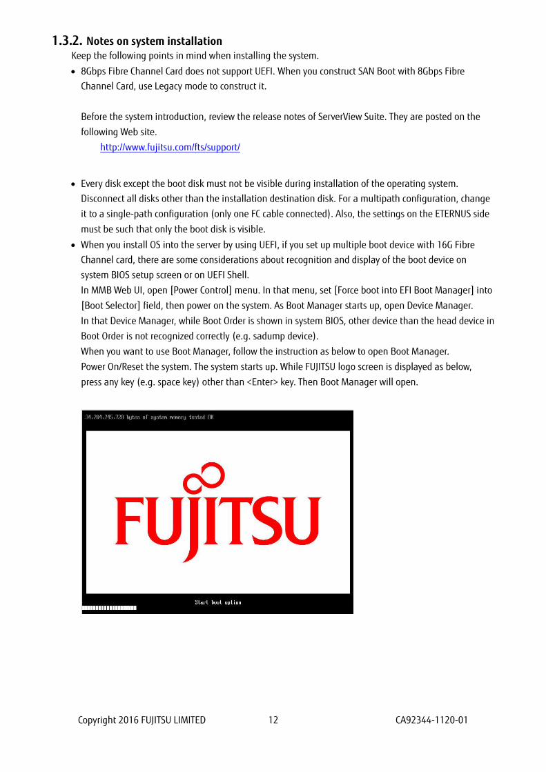
When you want to use Boot Manager, follow the instruction as below to open Boot Manager.
Power On/Reset the system. The system starts up. While FUJITSU logo screen is displayed as below,
press any key (e.g. space key) other than <Enter> key. Then Boot Manager will open.

Copyright 2016 FUJITSU LIMITED 13 CA92344-1120-01
1.3.3. Notes on system operation Keep the following points in mind when operating the system.
When the system is installed on UEFI BIOS, to set the by-path boot in the boot option is recommended
after the OS installation.
Procedure for the boot option setting by using SAN boot by-path.
1. Start the Partition.
During FUJITSU logo appears, press any key (except the [Enter] key) to display the Boot Manager
front page.
2. Select [Boot Maintenance Manager].
3. Select [Boot Option] in the [Boot Maintenance Manager] screen.
4. Select [Add Boot Option] in the [Boot Option] screen.
Copyright 2016 FUJITSU LIMITED 14 CA92344-1120-01
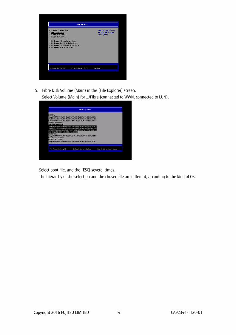
5. Fibre Disk Volume (Main) in the [File Explorer] screen.
Select Volume (Main) for …/Fibre (connected to WWN, connected to LUN).
Select boot file, and the [ESC] several times.
The hierarchy of the selection and the chosen file are different, according to the kind of OS.

Copyright 2016 FUJITSU LIMITED 15 CA92344-1120-01
Exp: Windows server
Select [<EFI>] -> [<Microsoft>] -> [<Boot>] -> [bootmgfw.efi].
Exp: RHEL server
Select [<EFI>] -> [<redhat>] -> [grub.efi].

Copyright 2016 FUJITSU LIMITED 16 CA92344-1120-01
6. Move the cursor on [Input the description] in the [Modify Boot Option Description] screen, and
then press the [Enter] key.
7. Enter the <<Boot Option Name (Main)>> in the [Please type in your data] screen.
(Create the Boot Option Name with five and more characters.)
8. Select [Commit Changes and Exit] in the [Modify Boot Option Description] screen, and then press
the [Enter] key.
Copyright 2016 FUJITSU LIMITED 17 CA92344-1120-01
9. Follow the procedures 5 to 8 to setup the Boot Option (Sub).
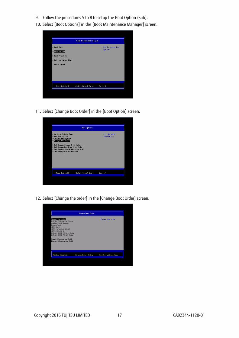
10. Select [Boot Options] in the [Boot Maintenance Manager] screen.
11. Select [Change Boot Order] in the [Boot Option] screen.
12. Select [Change the order] in the [Change Boot Order] screen.
Copyright 2016 FUJITSU LIMITED 18 CA92344-1120-01
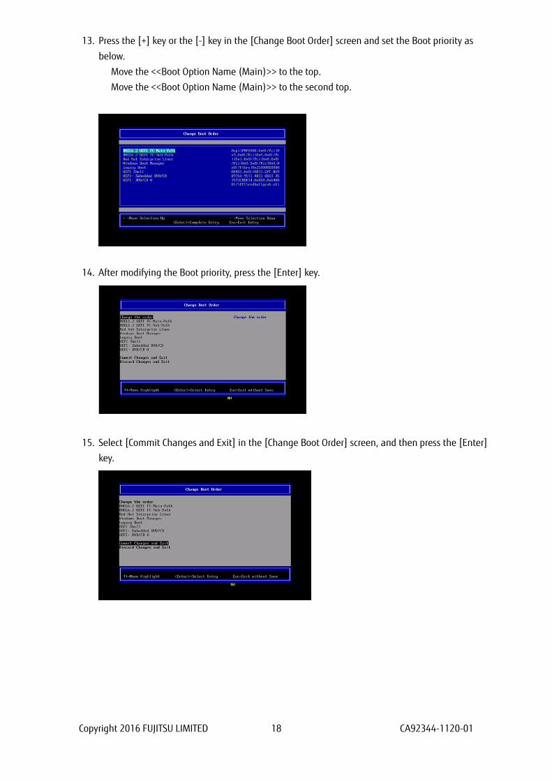
13. Press the [+] key or the [-] key in the [Change Boot Order] screen and set the Boot priority as
below.
Move the <<Boot Option Name (Main)>> to the top.
Move the <<Boot Option Name (Main)>> to the second top.
14. After modifying the Boot priority, press the [Enter] key.
15. Select [Commit Changes and Exit] in the [Change Boot Order] screen, and then press the [Enter]
key.
Copyright 2016 FUJITSU LIMITED 19 CA92344-1120-01
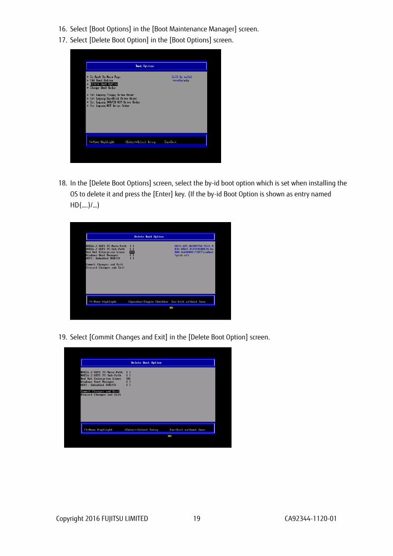
16. Select [Boot Options] in the [Boot Maintenance Manager] screen.
17. Select [Delete Boot Option] in the [Boot Options] screen.
18. In the [Delete Boot Options] screen, select the by-id boot option which is set when installing the
OS to delete it and press the [Enter] key. (If the by-id Boot Option is shown as entry named
HD(….)/…)
19. Select [Commit Changes and Exit] in the [Delete Boot Option] screen.

Copyright 2016 FUJITSU LIMITED 20 CA92344-1120-01
20. Select [Reset System] in the [Boot Maintenance Manager] screen, and then reboot the partition.
If you make some configuration changes, such as described below, after the installation of the system,
please initialize the settings of the FC card and do the settings of the FC card again. After that, be sure to
reboot the system.
- You register a dump device of sadump to the FC card.
- You make some configuration changes of SAN Storage and FC Switch (e.g. LUN mapping, host affinity,
port zoning, etc.).
- You alter boot OSs.
- To add LUN device, you register the device to the FC card. For details, refer to "2.1.5 Configure Boot
Device” or “3.1.6 Configure Boot Device”.
Copyright 2016 FUJITSU LIMITED 21 CA92344-1120-01
1.3.4. Notes on system operation Keep the following points in mind when operating the system.
Be sure to confirm that the SAN Storage and FC Switch are completely in the Ready state.
Record the dates and times of server switching (FC card replacement. Including move.) on separate
media. Prepare this media in case the possibly faulty part of the hardware can no longer be located in
an event log primary analysis, at a hardware failure, or at the occurrence of another problem.
When the FC card has been replaced with a maintenance part, the HBA UEFI/Legacy BIOS must be reset.
Also, the SAN storage unit must be reset.
In the SAN boot environment, OS boot may fail depending on the quality of the FC transmission path.
In such a case, use the FC Switch and SAN Storage unit to check the alarm or system status and identify
the faulty part. Then, select [Reset] from the [Power Control] window of the MMB Web-UI to restart the
system.
In a Linux environment, a SAN boot in a multipath configuration may be performed. To start up in
Rescue mode and automatically mount the ETERNUS disk in such cases, enable only one FC port in
advance of startup.
If the multipath configuration is left as is, the system may fail to start up normally. Even if you do not
use automatic mounting, we recommend enabling only one FC port in advance of startup in Rescue
mode in order to prevent operational errors.
1.4. ETERNUS Connection Settings
For details on the settings required on the ETERNUS when connecting to it, see the ETERNUS manuals at
the following website:
http://www.fujitsu.com/global/support/products/computing/storage/disk/manuals/
Copyright 2016 FUJITSU LIMITED 22 CA92344-1120-01
2. Configure Fibre Channel Card (8Gbps FC Card) This chapter describes the settings to be made on the 8Gbps FC Card in the PRIMEQUEST 2000 series
server. With the resultant settings, the system starts from an LUN of the SAN storage unit in the FC SAN
boot environment.
2.1. Steps of Configuring FC Card in Legacy BIOS Driver Version 3.24 or Later
This section describes the procedure for setting Legacy BIOS driver version 3.24 or later.
In case you operate the server with Legacy BIOS mode, you configure the FC card in Legacy BIOS.
※Sample screen below represents QLogic QLE2672 (Dual Port).
You can apply the following instructions even if you use QLE2560.
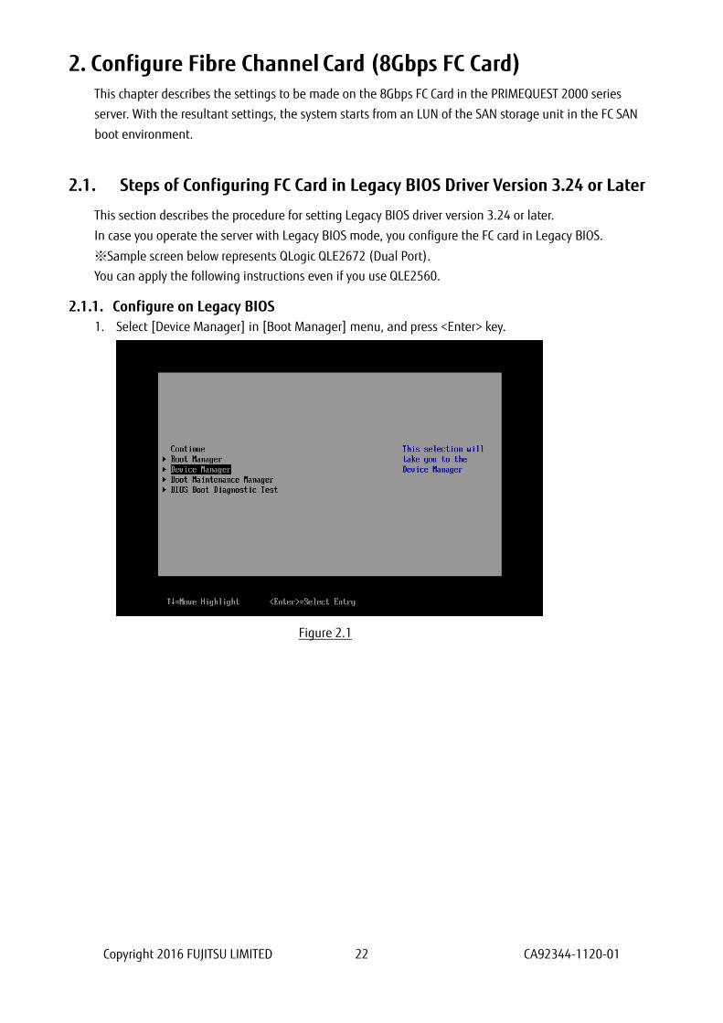
2.1.1. Configure on Legacy BIOS
1. Select [Device Manager] in [Boot Manager] menu, and press <Enter> key.
Figure 2.1

Copyright 2016 FUJITSU LIMITED 23 CA92344-1120-01
2. Select [PCI Subsystem Configuration] in [Device Manager] menu, press <Enter> key.
Figure 2.2
3. Select [PCI ROM Priority] in [PCI Subsystem Configuration] menu, and <Enter> key, then, in the
pulldown menu, select [Legacy ROM] and press <Enter> key.
Figure 2.3

Copyright 2016 FUJITSU LIMITED 24 CA92344-1120-01
4. Select [Commit Changes and Exit] in [PCI Subsystem Configuration] menu, and press <Enter> key.
Figure 2.4
5. Select [Boot Maintenance Manager] in [Boot Manager] main menu, and press <Enter> key.
Figure 2.5
Copyright 2016 FUJITSU LIMITED 25 CA92344-1120-01
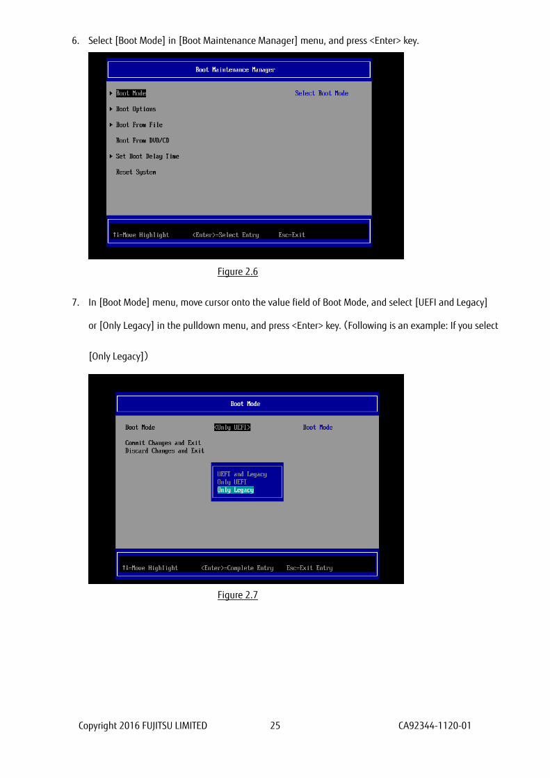
6. Select [Boot Mode] in [Boot Maintenance Manager] menu, and press <Enter> key.
Figure 2.6
7. In [Boot Mode] menu, move cursor onto the value field of Boot Mode, and select [UEFI and Legacy]
or [Only Legacy] in the pulldown menu, and press <Enter> key.(Following is an example: If you select
[Only Legacy])
Figure 2.7
Copyright 2016 FUJITSU LIMITED 26 CA92344-1120-01
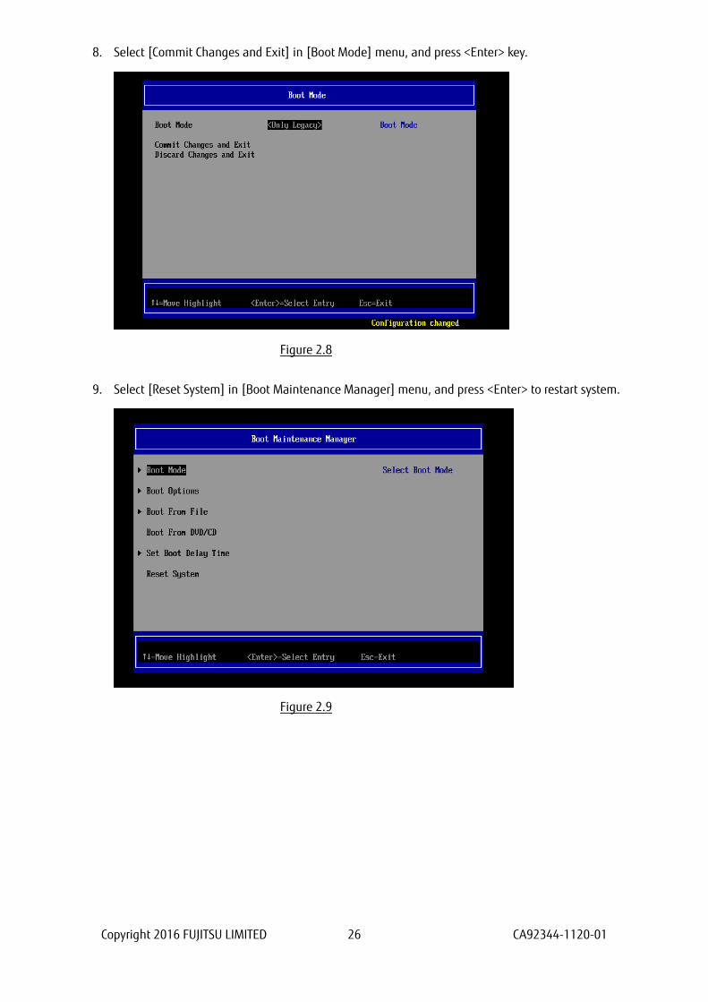
8. Select [Commit Changes and Exit] in [Boot Mode] menu, and press <Enter> key.
Figure 2.8
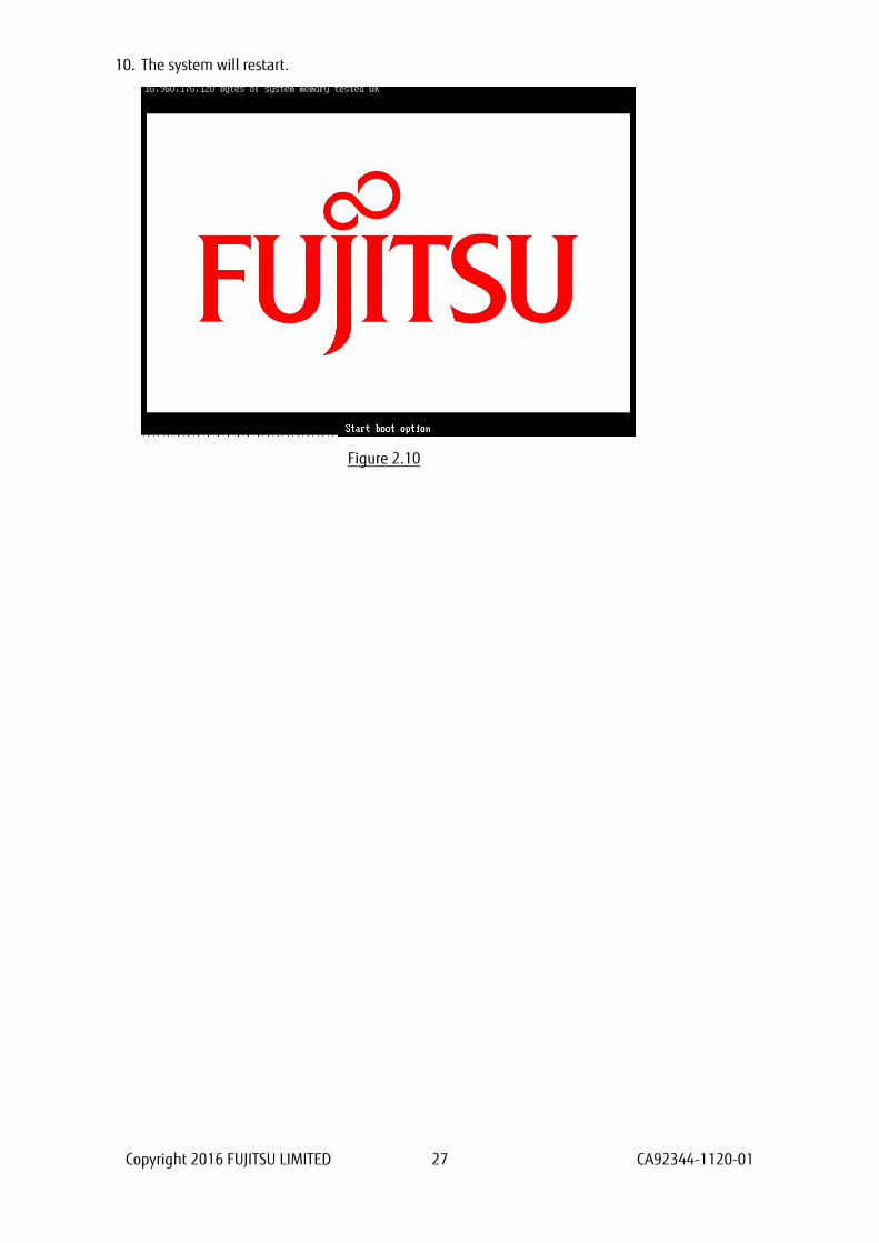
9. Select [Reset System] in [Boot Maintenance Manager] menu, and press <Enter> to restart system.
Figure 2.9
Copyright 2016 FUJITSU LIMITED 27 CA92344-1120-01
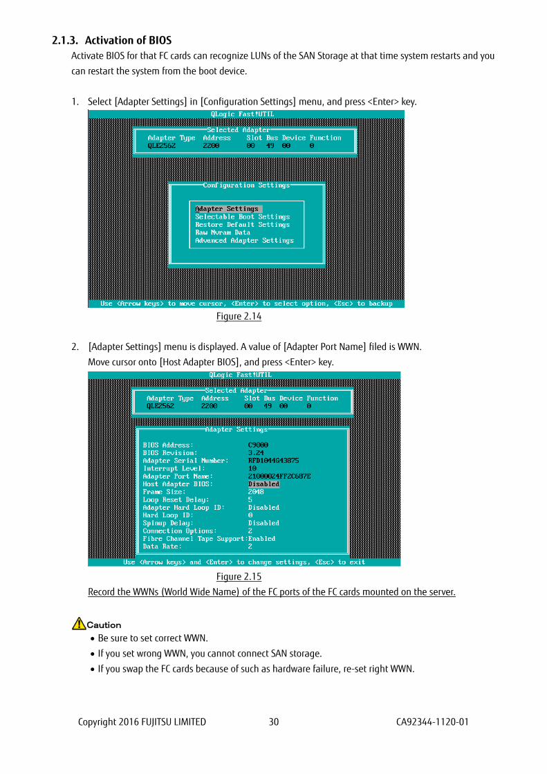
10. The system will restart.
Figure 2.10

Copyright 2016 FUJITSU LIMITED 28 CA92344-1120-01
2.1.2. Starting the utility of FC HBA
1. While the following screen is displayed, press [Alt] + [Q] key or [Ctrl] + [Q] key.
Figure 2.11

Copyright 2016 FUJITSU LIMITED 29 CA92344-1120-01
2. QLogic Fast!UTIL starts. It displays FC ports of FC card mounted on the server.
Select a FC port you would configure, and press <Enter> key.
Figure 2.12
3. A menu of the selected port is displayed. Select [Configuration Settings], and press <Enter> key.
Figure 2.13
Copyright 2016 FUJITSU LIMITED 30 CA92344-1120-01
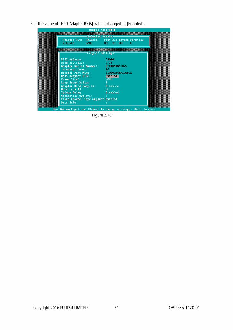
2.1.3. Activation of BIOS
Activate BIOS for that FC cards can recognize LUNs of the SAN Storage at that time system restarts and you
can restart the system from the boot device.
1. Select [Adapter Settings] in [Configuration Settings] menu, and press <Enter> key.
Figure 2.14
2. [Adapter Settings] menu is displayed. A value of [Adapter Port Name] filed is WWN.
Move cursor onto [Host Adapter BIOS], and press <Enter> key.
Figure 2.15
Record the WWNs (World Wide Name) of the FC ports of the FC cards mounted on the server.
Be sure to set correct WWN.
If you set wrong WWN, you cannot connect SAN storage.
If you swap the FC cards because of such as hardware failure, re-set right WWN.
Caution
Copyright 2016 FUJITSU LIMITED 31 CA92344-1120-01
3. The value of [Host Adapter BIOS] will be changed to [Enabled].
Figure 2.16

Copyright 2016 FUJITSU LIMITED 32 CA92344-1120-01
2.1.4. Setting of Connection Option and Data Rate
We describe the setting of Connection Option and Data Rate.
■Setting of Connection Option
1. Select [Adapter Settings] in [Configuration Settings] menu, press <Enter> key.
Figure 2.17
2. Move cursor onto [Connection Options] and press <Enter> key, in that option menu, select an option
appropriate to the SAN Fabric connection, and press <Enter> key.
Figure 2.18
Copyright 2016 FUJITSU LIMITED 33 CA92344-1120-01
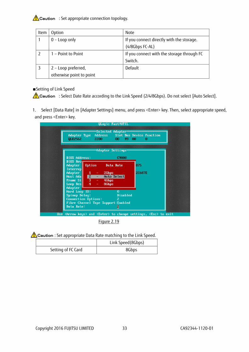
: Set appropriate connection topology.
Item Option Note
1 0 – Loop only If you connect directly with the storage.
(4/8Gbps FC-AL)
2 1 – Point to Point If you connect with the storage through FC
Switch.
3 2 – Loop preferred,
otherwise point to point
Default
■Setting of Link Speed
: Select Date Rate according to the Link Speed (2/4/8Gbps). Do not select [Auto Select].
1. Select [Data Rate] in [Adapter Settings] menu, and press <Enter> key. Then, select appropriate speed,
and press <Enter> key.
Figure 2.19
: Set appropriate Data Rate matching to the Link Speed.
Link Speed(8Gbps)
Setting of FC Card 8Gbps
Caution
Caution
Caution

Copyright 2016 FUJITSU LIMITED 34 CA92344-1120-01
2. Press <ESC> key, and select [Save changes], then, press <Enter> key to save the settings.
Figure 2.20
Configure FC Switch and Storage Device
When you configure FC Switch and Storage Device, select and set fixed value as data rate. Do not select
auto configuration.
When you configure ETERNUS, refer to manuals which are published in Web site as below.
http://www.fujitsu.com/global/support/products/computing/storage/disk/manuals/
Copyright 2016 FUJITSU LIMITED 35 CA92344-1120-01
2.1.5. Configure Boot Device
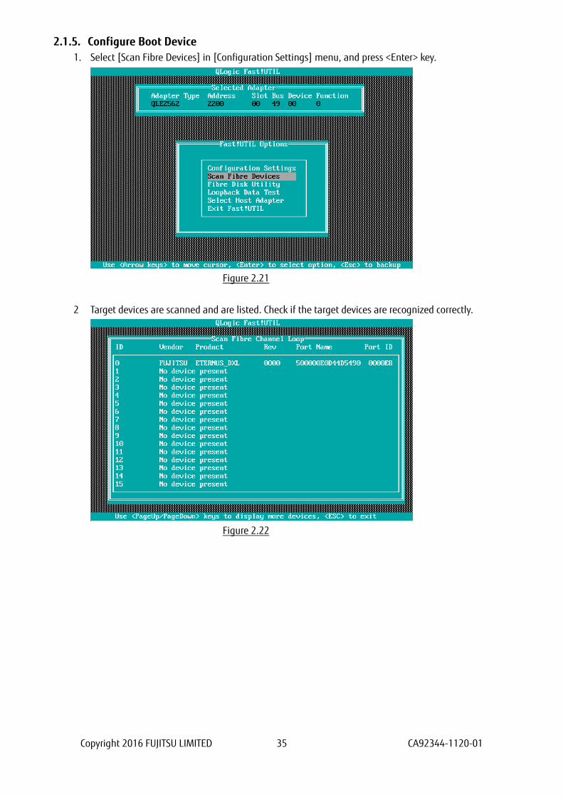
1. Select [Scan Fibre Devices] in [Configuration Settings] menu, and press <Enter> key.
Figure 2.21
2 Target devices are scanned and are listed. Check if the target devices are recognized correctly.
Figure 2.22

Copyright 2016 FUJITSU LIMITED 36 CA92344-1120-01
3. Select [Selectable Boot Settings] and press <Enter> key.
Figure 2.23
4. [Selectable Boot Settings] menu is opened, then, move cursor onto the setting field of [Selectable Boot],
and press <Enter> key.
Figure 2.24

Copyright 2016 FUJITSU LIMITED 37 CA92344-1120-01
5. [Selectable Boot] is Enabled as below.
Figure 2.25
6. Move cursor onto the field of the boot port as below, press <Enter> key.
Figure 2.26
Copyright 2016 FUJITSU LIMITED 38 CA92344-1120-01
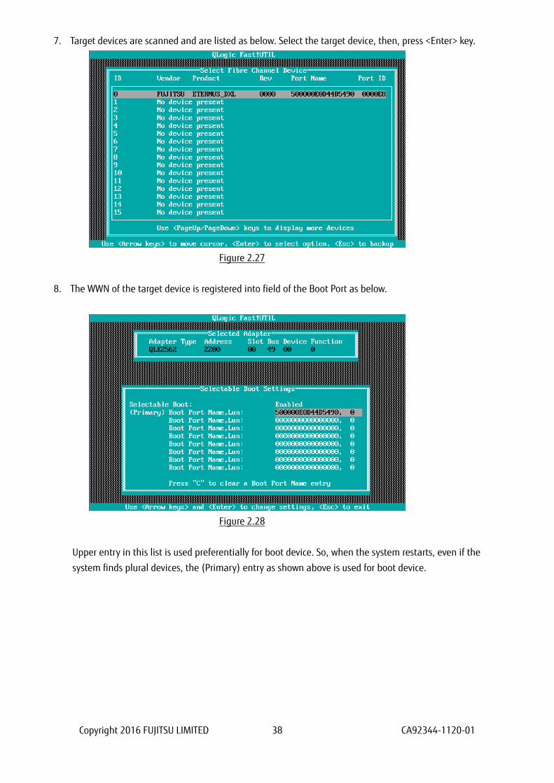
7. Target devices are scanned and are listed as below. Select the target device, then, press <Enter> key.
Figure 2.27
8. The WWN of the target device is registered into field of the Boot Port as below.
Figure 2.28
Upper entry in this list is used preferentially for boot device. So, when the system restarts, even if the
system finds plural devices, the (Primary) entry as shown above is used for boot device.

Copyright 2016 FUJITSU LIMITED 39 CA92344-1120-01
9. Press <ESC> key twice. A message is displayed, which queries whether you would save settings. So, select
[Save changes] and press <Enter> key.
Press <ESC> key again. A message is displayed as below.
Figure 2.29
10. In case you use multipath, you need to do setting against all the FC cards connected to the LUN of SAN
storage from which the system reboot. That settings are described in from “2.1.2 Start FC Card Utility” to
“2.1.4 Setting of Connect Option and Data Rate”.
After you installed OS and multipath driver, you need do setting against all the FC cards connected to the
LUN of SAN storage from which the system reboot. That settings are described in “2.1.5 Configure Boot
Device”.
After you have done all the settings, reset the system by doing [Reset] in [Power Control] page in MMB
Web-UI.

Copyright 2016 FUJITSU LIMITED 40 CA92344-1120-01
3. Configure Fibre Channel Card (16Gbps FC Card) This chapter describes procedure of configuration of 16Gbps FC card to boot from LUN of SAN storage in
SAN Boot environment.
※Sample screens showed hereafter use QLogic QLE2672(Dual Port).
3.1. Steps of Configuring 16Gbps FC Card in UEFI Driver version 6.08 or later
This section describes procedure of configuration of 16Gbps FC card in UEFI Driver which version is 6.08 or
later.
To boot system from LUN of SAN storage device in SAN boot environment, you need to do settings
described later against the all FC cards used in system boot.
In case you boot from LUN of SAN storage device, register the LUN into the FC card.
Screens shown hereafter are all example. They may be different by such as system configuration.
In case you set a storage device on SAN to be a dump device of sadump, you need to set the LUN
additionally using [Add Boot Device] of UEFI driver.
After you have done setting, you need to restart the system. After the restart of the partition, be sure to
perform the procedures described hereafter.
While FUJITSU logo is displayed as below, press any key (e.g. space key) other than <Enter> key.
If you have not done the settings described above, you can’t use the dump device(LUN).
Caution

Copyright 2016 FUJITSU LIMITED 41 CA92344-1120-01
Setting of dump device is to be done after OS installation.
When you configure sadump, refer to “PRIMEQUEST 2000 Series Installation Manual”(CA92344-0536)
--> “Chapter 5 Work after Operating System installation” --> “5.3 Setting of sadump” or “PRIMEQUEST
2000 Series Tool Reference”(CA92344-0539) --> “Chapter 6 Setting of sadump environment”.
Setting of FC card, you need to do for each port of the card.
In a partition, you need to make the firmware of all FC cards be the same one version. You can’t use
the FC cards with different version of firmware in a partition.
It is same for driver’s version of FC card.

Copyright 2016 FUJITSU LIMITED 42 CA92344-1120-01
3.1.1. Procedure of Configuration of 16Gbps FC card
Review the UEFI driver’s version on [Device Manager] menu which is opened from Boot Manager front
page.
1. In [Power Control] page of MMB Web-UI, set [Force boot into EFI Boot Manager] into [Boot Selector],
power on the partition.
2. Boot Manager front page is opened. Select [Device Manager], and press <Enter> key.
Figure 3.1

Copyright 2016 FUJITSU LIMITED 43 CA92344-1120-01
3. [Device Manager] menu is displayed.
Figure 3.2
※The order of devices displayed in [Devices List] can be changed every time you open [Device
Manager].
Note
Review version of UEFI driver. In case you use 16Gbps FC card, select [QLogic QLE2672 16Gb FC Adapter –
2100000xxxxxxxxx] in [Device Manager] menu to start the driver menu, and review [UEFI Driver Version]
in that menu.
Copyright 2016 FUJITSU LIMITED 44 CA92344-1120-01
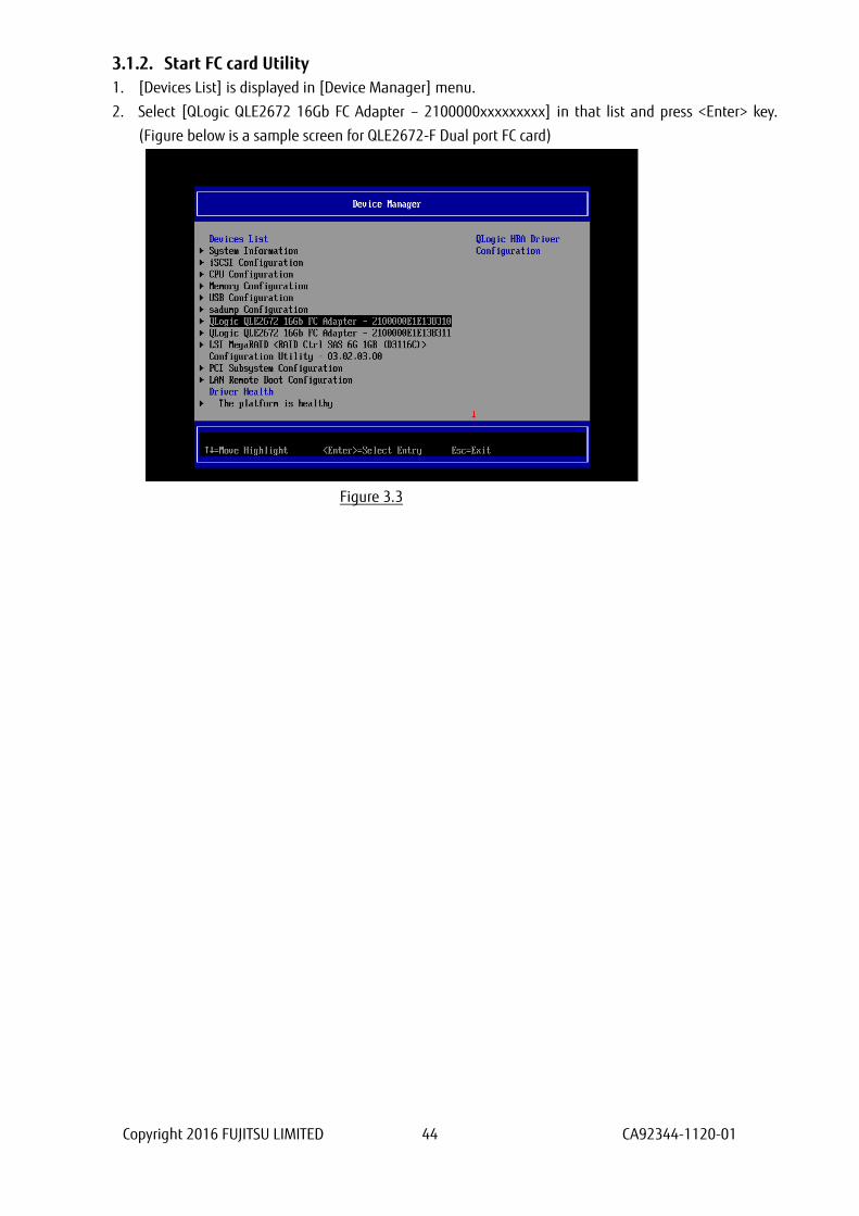
3.1.2. Start FC card Utility
1. [Devices List] is displayed in [Device Manager] menu.
2. Select [QLogic QLE2672 16Gb FC Adapter – 2100000xxxxxxxxx] in that list and press <Enter> key.
(Figure below is a sample screen for QLE2672-F Dual port FC card)
Figure 3.3
Copyright 2016 FUJITSU LIMITED 45 CA92344-1120-01
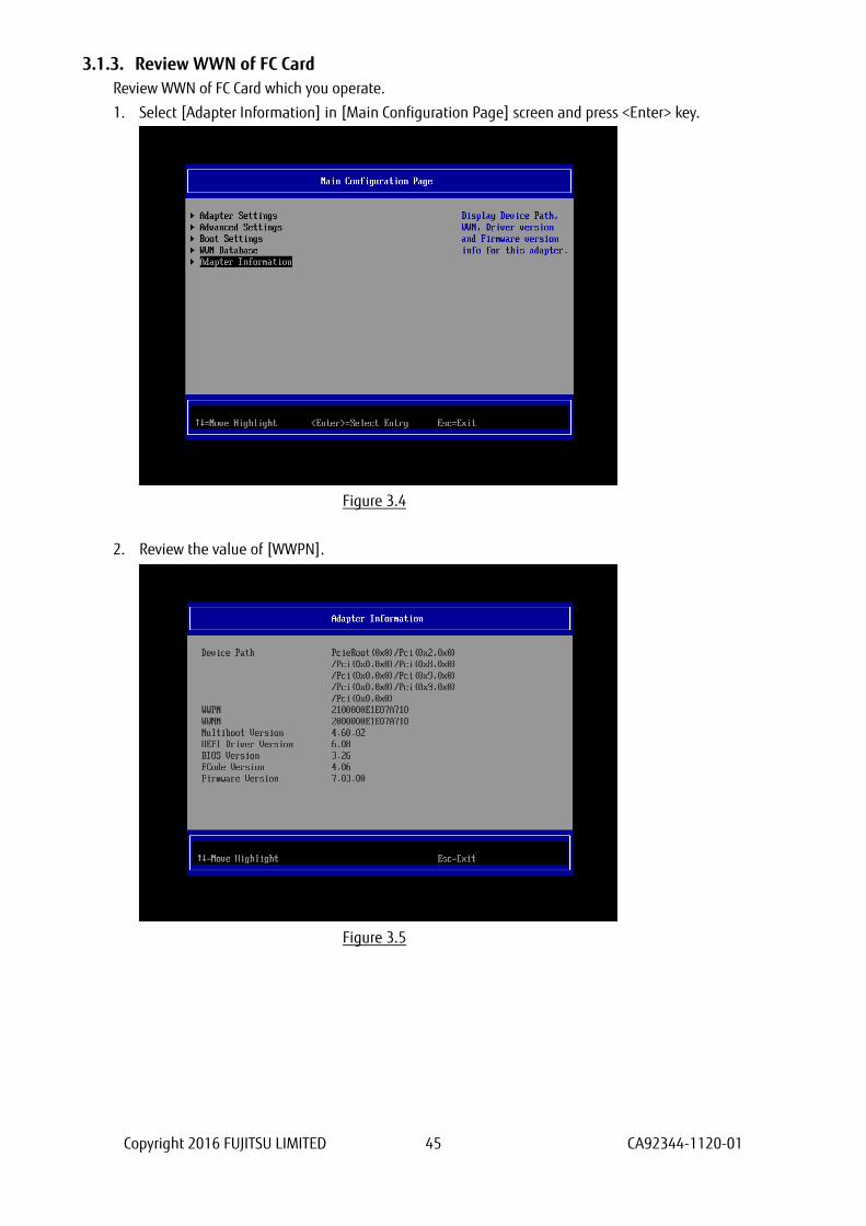
3.1.3. Review WWN of FC Card
Review WWN of FC Card which you operate.
1. Select [Adapter Information] in [Main Configuration Page] screen and press <Enter> key.
Figure 3.4
2. Review the value of [WWPN].
Figure 3.5
Copyright 2016 FUJITSU LIMITED 46 CA92344-1120-01
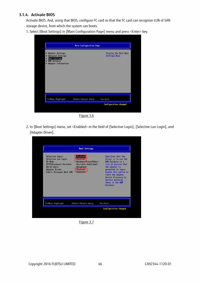
3.1.4. Activate BIOS
Activate BIOS. And, using that BIOS, configure FC card so that the FC card can recognize LUN of SAN
storage device, from which the system can boots.
1. Select [Boot Settings] in [Main Configuration Page] menu and press <Enter> key.
Figure 3.6
2. In [Boot Settings] menu, set <Enabled> in the field of [Selective Login], [Selective Lun Login], and
[Adapter Driver].
Figure 3.7
Copyright 2016 FUJITSU LIMITED 47 CA92344-1120-01
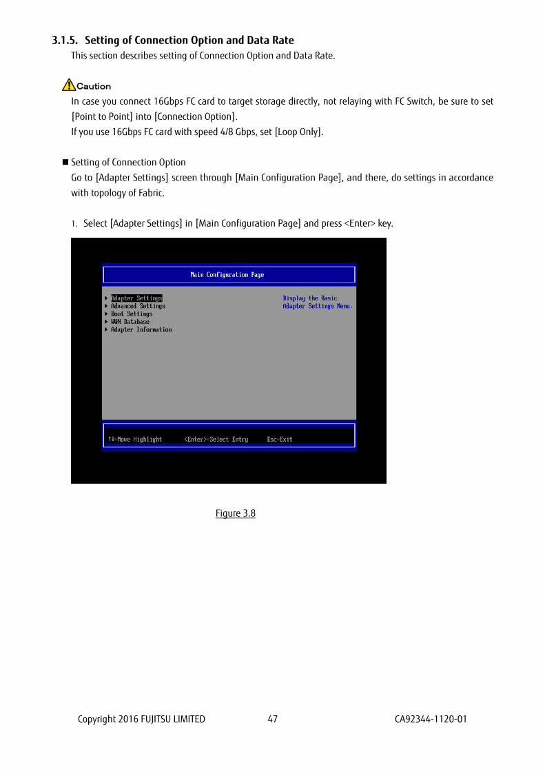
3.1.5. Setting of Connection Option and Data Rate
This section describes setting of Connection Option and Data Rate.
In case you connect 16Gbps FC card to target storage directly, not relaying with FC Switch, be sure to set
[Point to Point] into [Connection Option].
If you use 16Gbps FC card with speed 4/8 Gbps, set [Loop Only].
Setting of Connection Option
Go to [Adapter Settings] screen through [Main Configuration Page], and there, do settings in accordance
with topology of Fabric.
1. Select [Adapter Settings] in [Main Configuration Page] and press <Enter> key.
Figure 3.8
Caution

Copyright 2016 FUJITSU LIMITED 48 CA92344-1120-01
2. In [Adapter Settings] screen, select [Point to Point] in pulldown menu of [Connection Option] and
press <Enter> key.
Figure 3.9
: Set appropriate connection topology.
Item Option Note
1 0 – Loop only Connecting to storage directly. (4G/8G FC-AL)
2 1 – Point to Point (1) Connecting to storage directly with speed
16Gbps.
(2) Connecting to storage relaying FC Switch.
3 2 – Loop preferred, otherwise
point to point
Default value
Caution
Copyright 2016 FUJITSU LIMITED 49 CA92344-1120-01
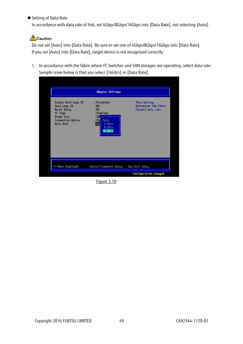
Setting of Data Rate
In accordance with data rate of link, set 4Gbps/8Gbps/16Gbps into [Data Rate], not selecting [Auto].
Do not set [Auto] into [Data Rate]. Be sure to set one of 4Gbps/8Gbps/16Gbps into [Data Rate].
If you set [Auto] into [Data Rate], target device is not recognized correctly.
1. In accordance with the fabric where FC Switches and SAN storages are operating, select data rate.
Sample scree below is that you select [16Gb/s] in [Data Rate].
Figure 3.10
Caution

Copyright 2016 FUJITSU LIMITED 50 CA92344-1120-01
2. After settings, return to [Main Configuration Page].
Figure 3.11
Configure FC Switch and SAN Storage
When you configure FC Switch and SAN Storage, select and set fixed value as data rate. Do not select auto
setting.
When you configure ETERNUS, read manuals which are published in Web site as below.
http://www.fujitsu.com/global/support/products/computing/storage/disk/manuals/

Copyright 2016 FUJITSU LIMITED 51 CA92344-1120-01
3.1.6. Configure Boot Device
There are some differences in configurations of boot device due to version of UEFI driver. We describe
those hereafter.
3.1.6.1. In case of UEFI Driver Version 6.08
1. Select [WWN Database] in [Main Configuration Page], and press <Enter> key.
Figure 3.12
2. Set WWPN of boot device into the field of [Drive 0 WWPN] manually.
Figure 3.13
Copyright 2016 FUJITSU LIMITED 52 CA92344-1120-01
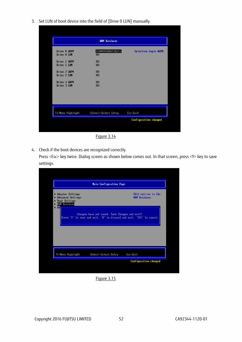
3. Set LUN of boot device into the field of [Drive 0 LUN] manually.
Figure 3.14
4. Check if the boot devices are recognized correctly.
Press <Esc> key twice. Dialog screen as shown below comes out. In that screen, press <Y> key to save
settings.
Figure 3.15
Copyright 2016 FUJITSU LIMITED 53 CA92344-1120-01
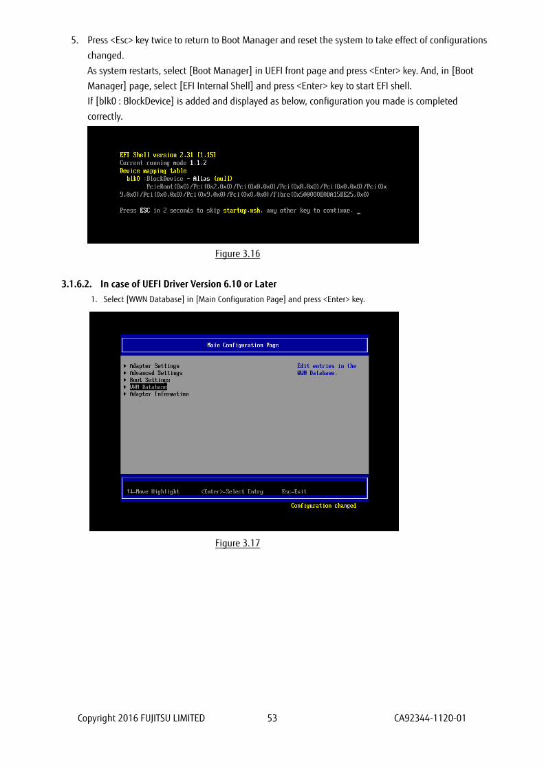
5. Press <Esc> key twice to return to Boot Manager and reset the system to take effect of configurations
changed.
As system restarts, select [Boot Manager] in UEFI front page and press <Enter> key. And, in [Boot
Manager] page, select [EFI Internal Shell] and press <Enter> key to start EFI shell.
If [blk0 : BlockDevice] is added and displayed as below, configuration you made is completed
correctly.
Figure 3.16
3.1.6.2. In case of UEFI Driver Version 6.10 or Later
1. Select [WWN Database] in [Main Configuration Page] and press <Enter> key.
Figure 3.17
Copyright 2016 FUJITSU LIMITED 54 CA92344-1120-01
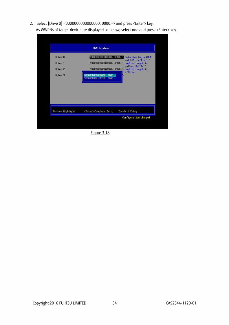
2. Select [Drive 0] <0000000000000000, 0000:-> and press <Enter> key.
As WWPNs of target device are displayed as below, select one and press <Enter> key.
Figure 3.18
Copyright 2016 FUJITSU LIMITED 55 CA92344-1120-01
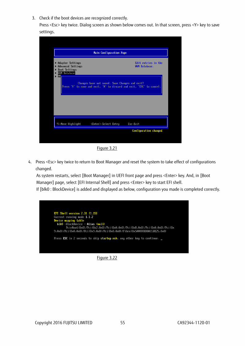
3. Check if the boot devices are recognized correctly.
Press <Esc> key twice. Dialog screen as shown below comes out. In that screen, press <Y> key to save
settings.
Figure 3.21
4. Press <Esc> key twice to return to Boot Manager and reset the system to take effect of configurations
changed.
As system restarts, select [Boot Manager] in UEFI front page and press <Enter> key. And, in [Boot
Manager] page, select [EFI Internal Shell] and press <Enter> key to start EFI shell.
If [blk0 : BlockDevice] is added and displayed as below, configuration you made is completed correctly.
Figure 3.22

Copyright 2016 FUJITSU LIMITED 56 CA92344-1120-01
Important
If the devices you had set are not displayed in EFI shell, the settings of SAN storage and FC Switch or the
physical link may be incorrect. Please check again if those settings are correct.
In case you register sadump device additionally, do from step 2 of the procedures as described above. If
you do not need to register sadump device, go to section 3.1.7.
In case you use multipath, you need to do setting against all the FC cards connected to the LUN of SAN
storage from which the system boots. That settings are described in from “3.1.2 Start FC Card Utility” to
“3.1.5 Setting of Connect Option and Data Rate”.
After you installed OS and multipath driver, you need do setting against all the FC cards connected to the
LUN of SAN storage from which the system boots. That settings are described in “3.1.6 Configure Boot
Device”.
After you have done all the settings, press <Esc> key to return to Device Manager menu.
Copyright 2016 FUJITSU LIMITED 57 CA92344-1120-01
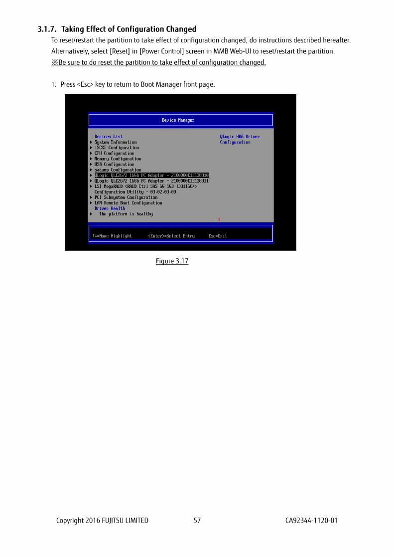
3.1.7. Taking Effect of Configuration Changed
To reset/restart the partition to take effect of configuration changed, do instructions described hereafter.
Alternatively, select [Reset] in [Power Control] screen in MMB Web-UI to reset/restart the partition.
※Be sure to do reset the partition to take effect of configuration changed.
1. Press <Esc> key to return to Boot Manager front page.
Figure 3.17
Copyright 2016 FUJITSU LIMITED 58 CA92344-1120-01
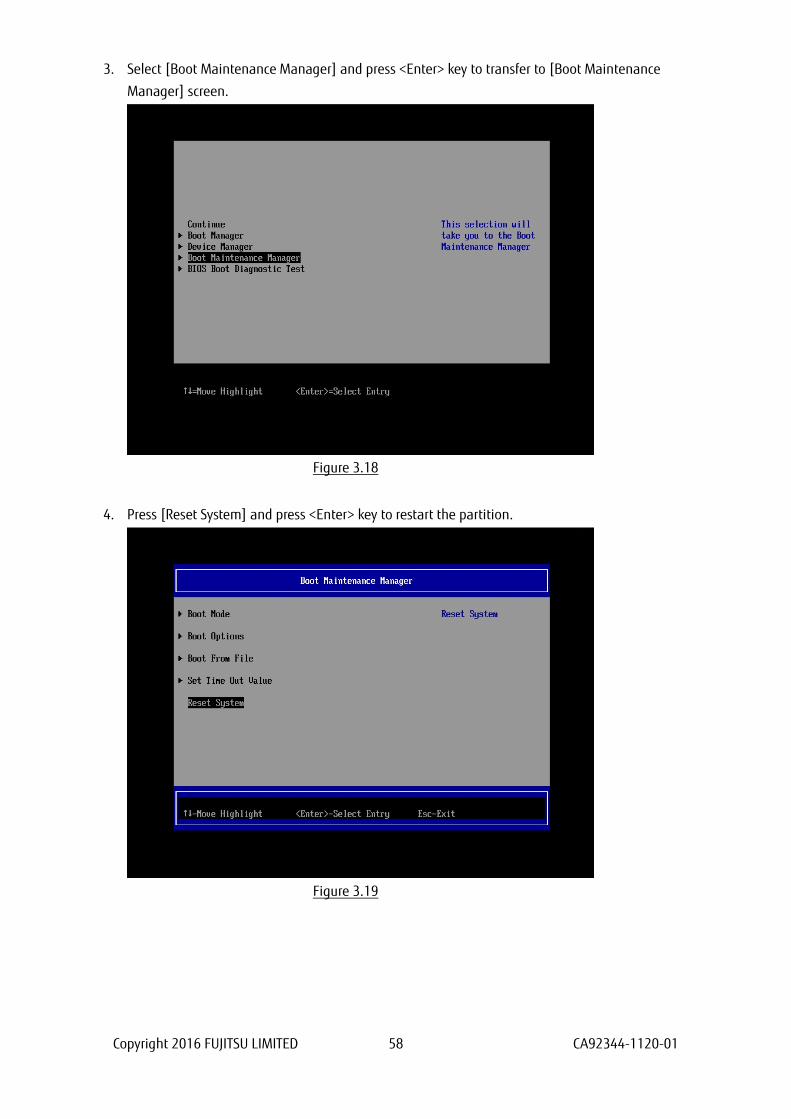
3. Select [Boot Maintenance Manager] and press <Enter> key to transfer to [Boot Maintenance
Manager] screen.
Figure 3.18
4. Press [Reset System] and press <Enter> key to restart the partition.
Figure 3.19
Copyright 2016 FUJITSU LIMITED 59 CA92344-1120-01
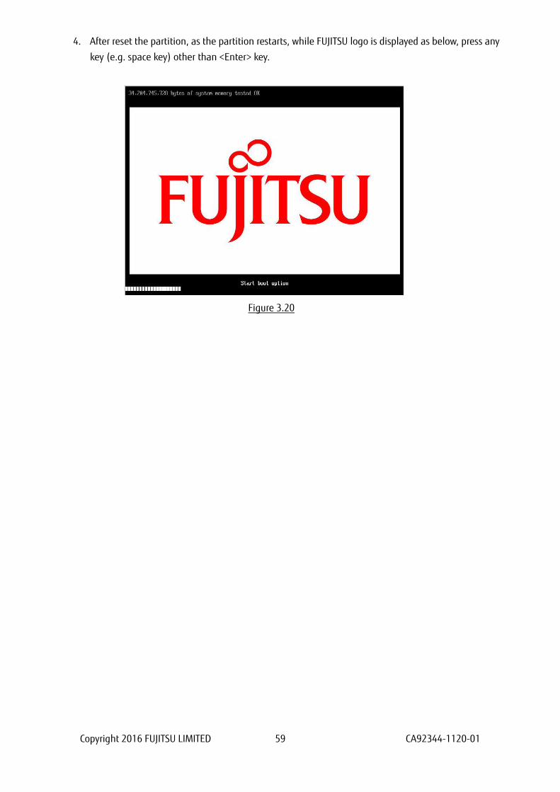
4. After reset the partition, as the partition restarts, while FUJITSU logo is displayed as below, press any
key (e.g. space key) other than <Enter> key.
Figure 3.20
Copyright 2016 FUJITSU LIMITED 60 CA92344-1120-01
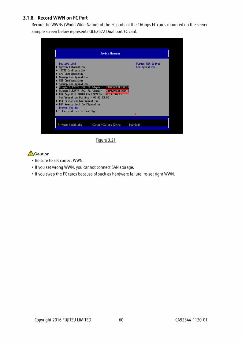
3.1.8. Record WWN on FC Port
Record the WWNs (World Wide Name) of the FC ports of the 16Gbps FC cards mounted on the server.
Sample screen below represents QLE2672 Dual port FC card.
Figure 3.21
• Be sure to set correct WWN.
• If you set wrong WWN, you cannot connect SAN storage.
• If you swap the FC cards because of such as hardware failure, re-set right WWN.
Caution
Copyright 2016 FUJITSU LIMITED 61 CA92344-1120-01
3.2. Steps of Configuring 16Gbps FC Card in Legacy BIOS Driver version 3.26
or later
This chapter describes procedure of configuration of 16Gbps FC card with Legacy BIOS driver which version
is 3.26 or later.
Refer the section 2.1.2 about starting system with Legacy BIOS mode.
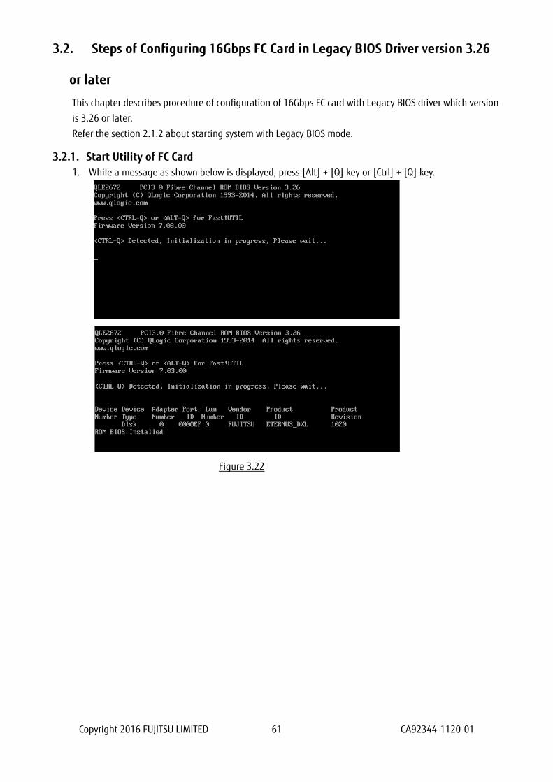
3.2.1. Start Utility of FC Card
1. While a message as shown below is displayed, press [Alt] + [Q] key or [Ctrl] + [Q] key.
Figure 3.22
Copyright 2016 FUJITSU LIMITED 62 CA92344-1120-01
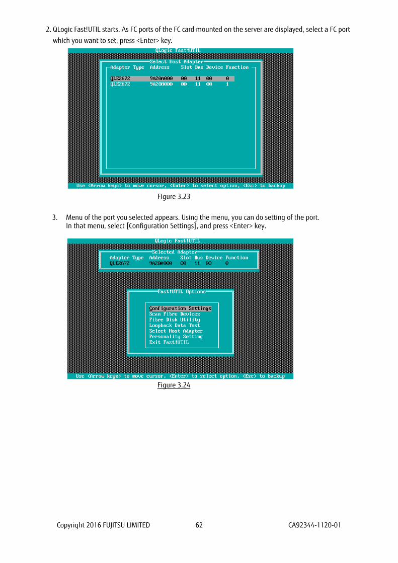
2. QLogic Fast!UTIL starts. As FC ports of the FC card mounted on the server are displayed, select a FC port
which you want to set, press <Enter> key.
Figure 3.23
3. Menu of the port you selected appears. Using the menu, you can do setting of the port. In that menu, select [Configuration Settings], and press <Enter> key.
Figure 3.24
Copyright 2016 FUJITSU LIMITED 63 CA92344-1120-01
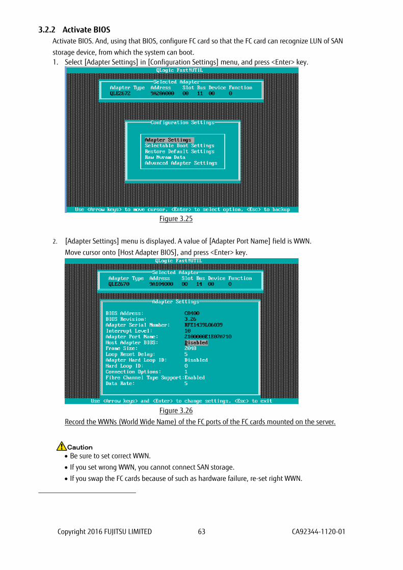
3.2.2 Activate BIOS
Activate BIOS. And, using that BIOS, configure FC card so that the FC card can recognize LUN of SAN
storage device, from which the system can boot.
1. Select [Adapter Settings] in [Configuration Settings] menu, and press <Enter> key.
Figure 3.25
2. [Adapter Settings] menu is displayed. A value of [Adapter Port Name] field is WWN.
Move cursor onto [Host Adapter BIOS], and press <Enter> key.
Figure 3.26
Record the WWNs (World Wide Name) of the FC ports of the FC cards mounted on the server.
Be sure to set correct WWN.
If you set wrong WWN, you cannot connect SAN storage.
If you swap the FC cards because of such as hardware failure, re-set right WWN.
Caution
Copyright 2016 FUJITSU LIMITED 64 CA92344-1120-01
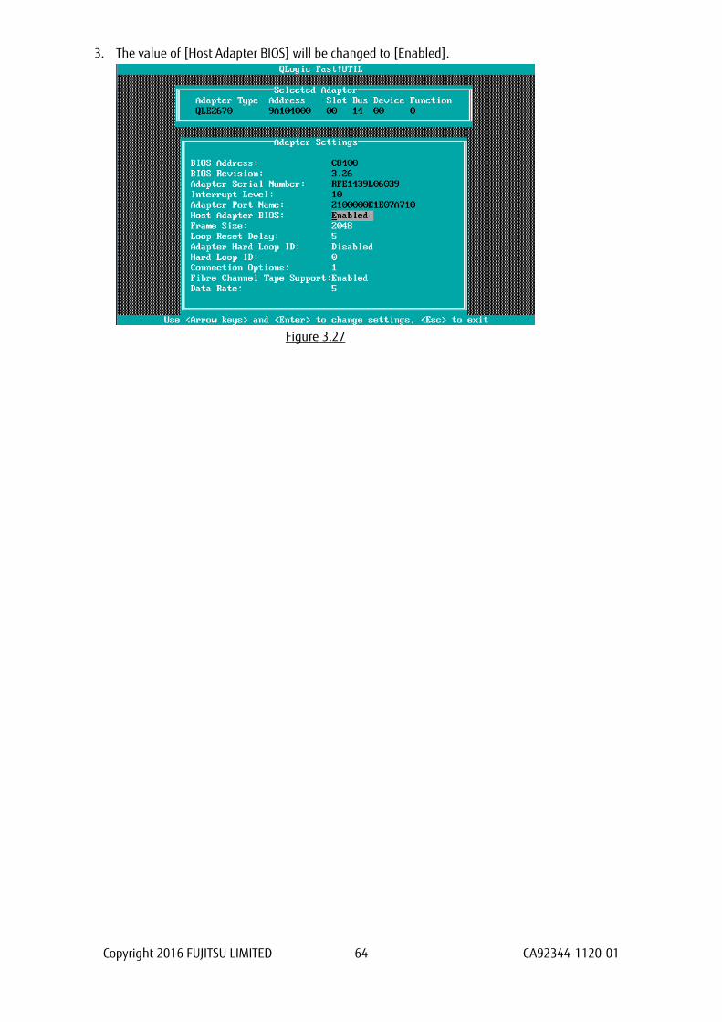
3. The value of [Host Adapter BIOS] will be changed to [Enabled].
Figure 3.27
Copyright 2016 FUJITSU LIMITED 65 CA92344-1120-01
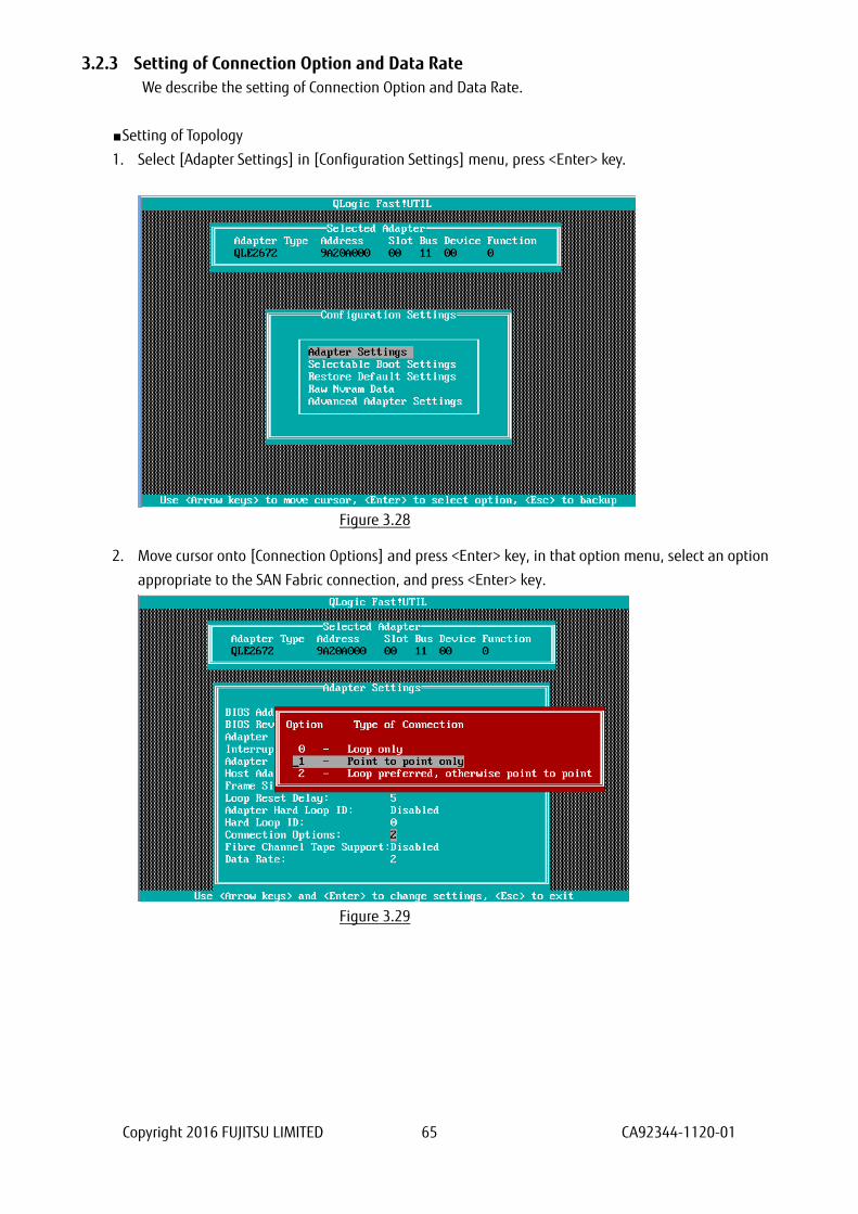
3.2.3 Setting of Connection Option and Data Rate
We describe the setting of Connection Option and Data Rate.
■Setting of Topology
1. Select [Adapter Settings] in [Configuration Settings] menu, press <Enter> key.
Figure 3.28
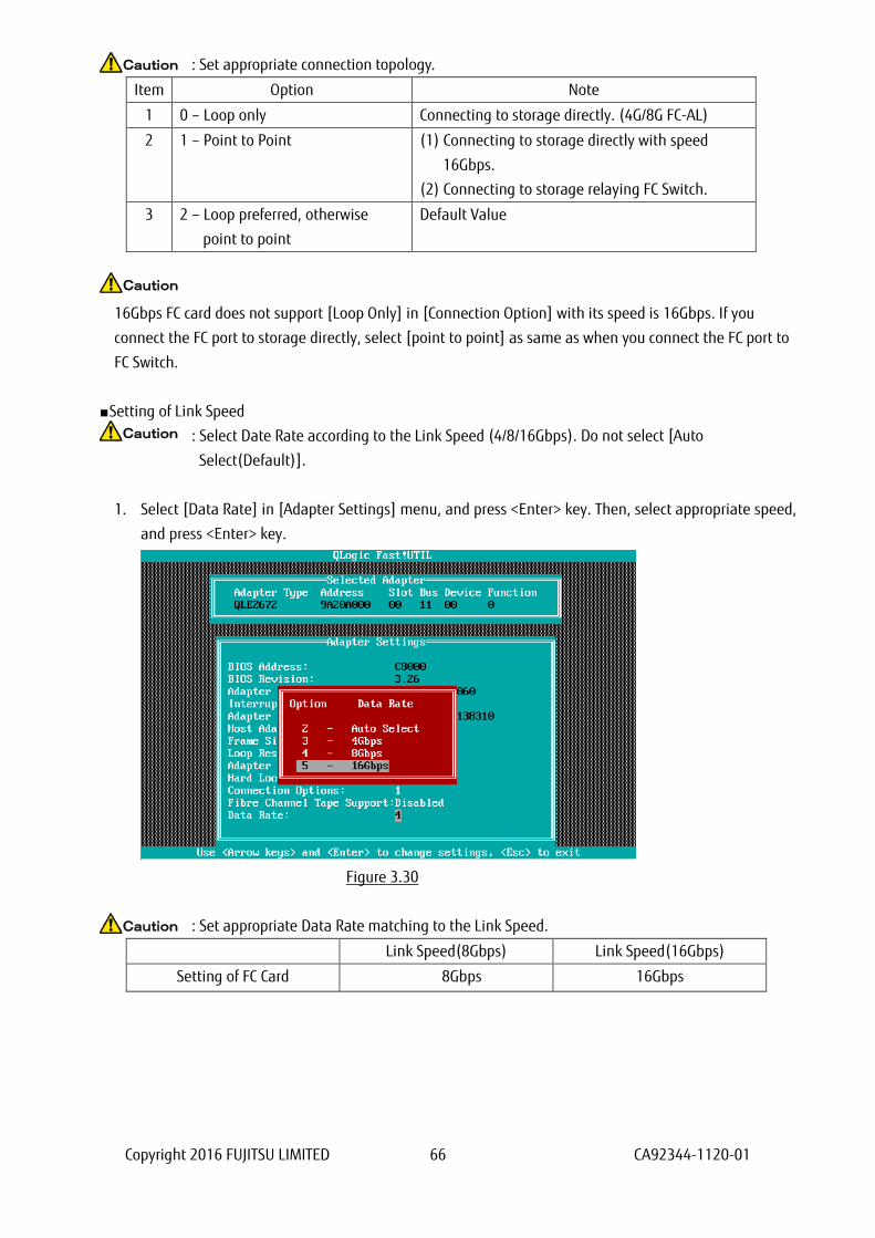
2. Move cursor onto [Connection Options] and press <Enter> key, in that option menu, select an option
appropriate to the SAN Fabric connection, and press <Enter> key.
Figure 3.29
Copyright 2016 FUJITSU LIMITED 66 CA92344-1120-01
: Set appropriate connection topology.
Item Option Note
1 0 – Loop only Connecting to storage directly. (4G/8G FC-AL)
2 1 – Point to Point (1) Connecting to storage directly with speed
16Gbps.
(2) Connecting to storage relaying FC Switch.
3 2 – Loop preferred, otherwise
point to point
Default Value
16Gbps FC card does not support [Loop Only] in [Connection Option] with its speed is 16Gbps. If you
connect the FC port to storage directly, select [point to point] as same as when you connect the FC port to
FC Switch.
■Setting of Link Speed
: Select Date Rate according to the Link Speed (4/8/16Gbps). Do not select [Auto
Select(Default)].
1. Select [Data Rate] in [Adapter Settings] menu, and press <Enter> key. Then, select appropriate speed,
and press <Enter> key.
Figure 3.30
: Set appropriate Data Rate matching to the Link Speed.
Link Speed(8Gbps) Link Speed(16Gbps)
Setting of FC Card 8Gbps 16Gbps
Caution
Caution
Caution
Caution

Copyright 2016 FUJITSU LIMITED 67 CA92344-1120-01
2. Press <Esc> key twice, and select [Save changes] and press <Enter> key to save the settings.
Figure 3.31
Configure FC Switch and Storage Device
When you configure FC Switch and Storage Device, select and set fixed value as data rate. Do not select
auto configuration.
When you configure ETERNUS, refer to manuals which are published in Web site as below.
http://www.fujitsu.com/global/support/products/computing/storage/disk/manuals/
Copyright 2016 FUJITSU LIMITED 68 CA92344-1120-01
3.2.4 Configure Boot Device
Configure boot devices for SAN Boot.
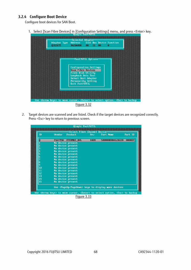
1. Select [Scan Fibre Devices] in [Configuration Settings] menu, and press <Enter> key.
Figure 3.32
2. Target devices are scanned and are listed. Check if the target devices are recognized correctly. Press <Esc> key to return to previous screen.
Figure 3.33

Copyright 2016 FUJITSU LIMITED 69 CA92344-1120-01
3. Select [Selectable Boot Settings] in [Configuration Settings] menu and press <Enter> key.
Figure 3.34
4. Move cursor to [Selectable Boot] and press <Enter> key to change the value to [Enabled].
At the setting field of [(Primary) Boot Port Name, Lun:], select a WWN which had been reviewed as
boot device’s WWN in step 2 above, and press <Enter> key.
Selected boot device’s WWN is registered and displayed as below.
Press <Esc> key to return to previous screen.
Figure 3.35
Note
If the devices you had set are not displayed in the menu, the settings of SAN Storage and FC Switch
or the physical link may be incorrect. Please check again if those settings are correct.
Copyright 2016 FUJITSU LIMITED 70 CA92344-1120-01
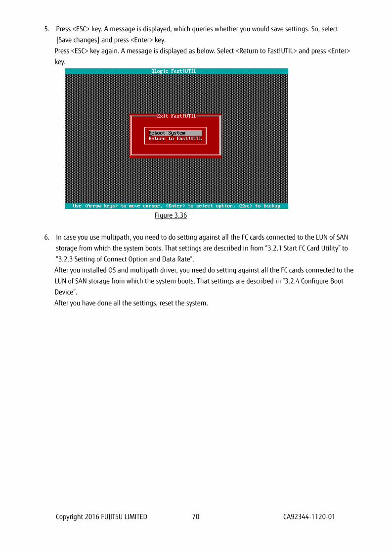
5. Press <ESC> key. A message is displayed, which queries whether you would save settings. So, select
[Save changes] and press <Enter> key.
Press <ESC> key again. A message is displayed as below. Select <Return to Fast!UTIL> and press <Enter>
key.
Figure 3.36
6. In case you use multipath, you need to do setting against all the FC cards connected to the LUN of SAN
storage from which the system boots. That settings are described in from “3.2.1 Start FC Card Utility” to
“3.2.3 Setting of Connect Option and Data Rate”.
After you installed OS and multipath driver, you need do setting against all the FC cards connected to the
LUN of SAN storage from which the system boots. That settings are described in “3.2.4 Configure Boot
Device”.
After you have done all the settings, reset the system.

Copyright 2016 FUJITSU LIMITED 71 CA92344-1120-01
4. Considerations on Installing Windows Server This chapter describes considerations on installing Windows Server in SAN Boot Environment.
4.1. Installing Windows Server
Refer to OS installation guide for details in installation of Windows Server.
4.1.1. Preparing for Installation of Windows Server
Prepare to install Windows Server to the server.
For details on the preparation, refer to manual below.
“PRIMEQUEST 2000 Series Installation Manual”(CA92344-0536) --> “4.3.1 Presetting”
When you configure multipath, disconnect the secondary cable from the server PRIMEQUEST 2000 series.
In fact, till the installation of OS and multipath driver is completed, make the connection a single path
(only one FC cable).
If you do OS installation with multipath, the OS installation is not done correctly. Prior to the OS
installation, disconnect the secondary FC path manually.
4.1.2. Setting of Boot Order
Please do settings, referring manual below.
“PRIMEQUEST 2000 Series Installation Manual” (CA92344-0536) --> “Chapter 4 Installation of Operating
System and bundled software” --> ”4.4.3 Installation of operating system” “Oparation2” --> “Note”.
4.1.3 Settings after OS Installation
Please do settings, referring manual below.
“PRIMEQUEST 2000 Series Installation Manual”(CA92344-0536) --> “Chapter 5 Work after Operating
System Installation” or “Chapter 6 Work after installation”.
Copyright 2016 FUJITSU LIMITED 72 CA92344-1120-01
4.1.4 Installation of QConverge Console
1. Install QConverge Console.
2. For installation of QConverge Console, refer “Installation of QConverge Console” in “Fibre Channel Card
Manual”.
During the installation of QConverge Console, you need to keep the connection a single path.
In fact, you need to connect it with one FC cable.
4.1.5 Installation of Multipath Driver
Install multipath driver. For installation of multipath driver, refer the instruction manual of the multipath
driver you use.
4.1.6 Reconnecting of Multipath
Restore the system to original state following steps below.
At first, shutdown the partition. After power-off of the partition, reconnect the FC cable had been
disconnected, and then restart the partition.
In case you use HDDs built-in the server, during you install OS, unmount them from the server. After you
finished the OS installation and the multipath boot is done successfully, shutdown the system and mount
the built-in HDDs.
4.2 Considerations on Storage and Its Connection
Depending on the storage which is connected, you may change the configuration of FC card. For details,
refer the storage’s manual.
For the required configuration of ETERNUS, refer the manuals published in Web site shown below.
http://www.fujitsu.com/global/support/products/computing/storage/disk/manuals/
Copyright 2016 FUJITSU LIMITED 73 CA92344-1120-01
5. Considerations on Installing Linux This chapter describes considerations on installing Linux in SAN Boot Environment.
5.1. Installing Linux
Refer to OS installation guide for details in installation of Linux.
5.1.1. Preparing for Installation of Linux
Prepare to install Linux to the server.
For details on the preparation, refer to manual below.
“PRIMEQUEST 2000 Series Installation Manual” (CA92344-0536) “4.3.1 Presetting”
When you configure multipath, disconnect the secondary cable from the server PRIMEQUEST 2000 series.
In fact, till the installation of OS and multipath driver is completed, make the connection a single path
(only one FC cable).
If you do OS installation with multipath, the OS installation is not done correctly. Prior to the OS
installation, disconnect the secondary FC path manually.
5.1.2. Setting of Boot Order
Please do settings, referring manual below.
“PRIMEQUEST 2000 Series Installation Manual” (CA92344-0536) - “Chapter 4 Installation of Operating
System and bundled software” - “4.4.3 Installation of operating system” - “Operations 2” “Note”.
5.1.3. Settings after OS Installation
Please do settings, referring manual below,
“PRIMEQUEST 2000 Series Installation Manual”(CA92344-0536) “Chapter 5 OS Work after Operating
System installation” or “Chapter 6 Work after installation”.

Copyright 2016 FUJITSU LIMITED 74 CA92344-1120-01
5.1.4. Installation of QConverge Console
1. Install QConverge Console.
2. For installation of QConverge Console, refer “Installation of QConverge Console” in “Fibre Channel Card
Manual”.
During the installation of QConverge Console, you need to keep the connection a single path.
In fact, you need to connect it with one FC cable.
5.1.5. Installation of Multipath Driver
Install multipath driver. For installation of multipath driver, refer the instruction manual of the multipath
driver you use.
5.1.6. Reconnecting of Multipath
Restore the system to original state following steps below.
At first, shutdown the partition. After power-off of the partition, reconnect the FC cable that had been
disconnected, and then restart the partition.
In case you use HDDs built-in the server, during you install OS, unmount them from the server. After you
finished the OS installation and the multipath boot is done successfully, shutdown the system and mount
the built-in HDDs.
Copyright 2016 FUJITSU LIMITED 75 CA92344-1120-01
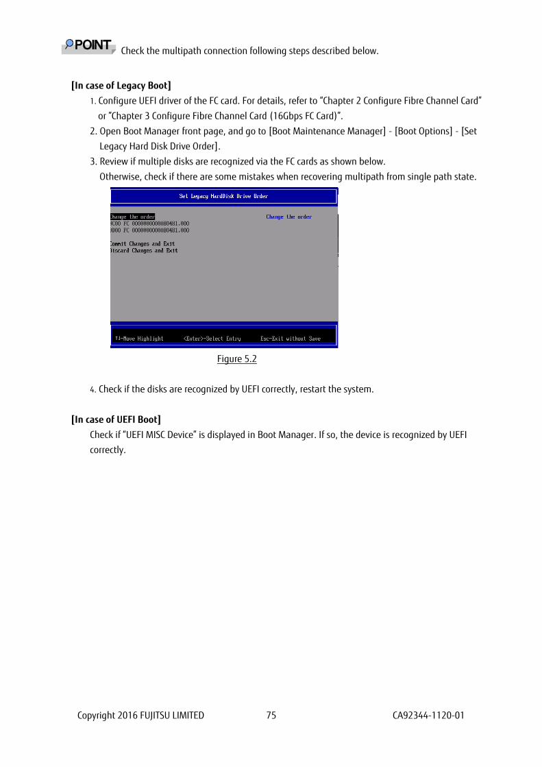
Check the multipath connection following steps described below.
[In case of Legacy Boot]
1. Configure UEFI driver of the FC card. For details, refer to “Chapter 2 Configure Fibre Channel Card”
or ”Chapter 3 Configure Fibre Channel Card (16Gbps FC Card)”.
2. Open Boot Manager front page, and go to [Boot Maintenance Manager] - [Boot Options] - [Set
Legacy Hard Disk Drive Order].
3. Review if multiple disks are recognized via the FC cards as shown below.
Otherwise, check if there are some mistakes when recovering multipath from single path state.
Figure 5.2
4. Check if the disks are recognized by UEFI correctly, restart the system.
[In case of UEFI Boot]
Check if “UEFI MISC Device” is displayed in Boot Manager. If so, the device is recognized by UEFI
correctly.
Copyright 2016 FUJITSU LIMITED 76 CA92344-1120-01
5.2. Using Built-in Disk with Linux
In case you use built-in disks, you need to configure boot order so as the boot from SAN disk is higher
than the boot from built-in disk.
After you install OS to the server, do procedures described hereafter.
All screenshots shown hereafter are example, so they may vary depending on the system configuration.
5.2.1. Check Disk Connection before mounting Built-in Disk
Do a following command on the running partition, check the current state of disk connections.
# ls -l /dev/disk/by-id
5.2.2. Mount Built-in Disk
Shut down the partition.
# shutdown -h now
After power-off the partition, mount the built-in disks to the server.
5.2.3. Configure RAID of Built-in Disk (with Disk Unit Array Card)
For details on configuring RAID of built–in hard disks, refer “LSI MegaRAID SAS2.0 Software / LSI
MegaRAID 12G Software”.
5.2.4. Configuration on UEFI
Open Boot Manager front page.
In case you do Legacy boot, follow procedures below to set boot options.
Go to [Boot Maintenance Manger] --> [Boot Options] --> [Change Legacy HDD Boot Priority], there,
assign the disk, which is configured in SAN storage, to the highest priority to boot.
In case you do UEFI boot, follow procedures below to set boot options.
Go to [Boot Maintenance Manger] --> [Boot Options] --> [Change Boot Order], there, assign the disk,
which is configured in SAN storage, the highest priority to boot.
If built-in disks are recognized in sequence of UEFI boot, that is displayed as “UEFI SCSI Device” in Boot
Manager.
Sample screens showed hereafter represents case of Legacy Boot.

Copyright 2016 FUJITSU LIMITED 77 CA92344-1120-01
Start Boot Manager Front Page
1. Power on the partition.
2. (After 1 or 2 minutes) screen as shown below is displayed. While FUJITSU logo is displayed as shown
below, press any key (e.g. space key) other than <Enter> key.
Figure 5.4
3. Boot Manager front page is displayed. Select [Boot Maintenance Manager], and press <Enter> key.
Figure 5.3

Copyright 2016 FUJITSU LIMITED 78 CA92344-1120-01
4. [Boot Maintenance Manager] is displayed. Select [Boot Options], and press <Enter> key.
Figure 5.4
Copyright 2016 FUJITSU LIMITED 79 CA92344-1120-01
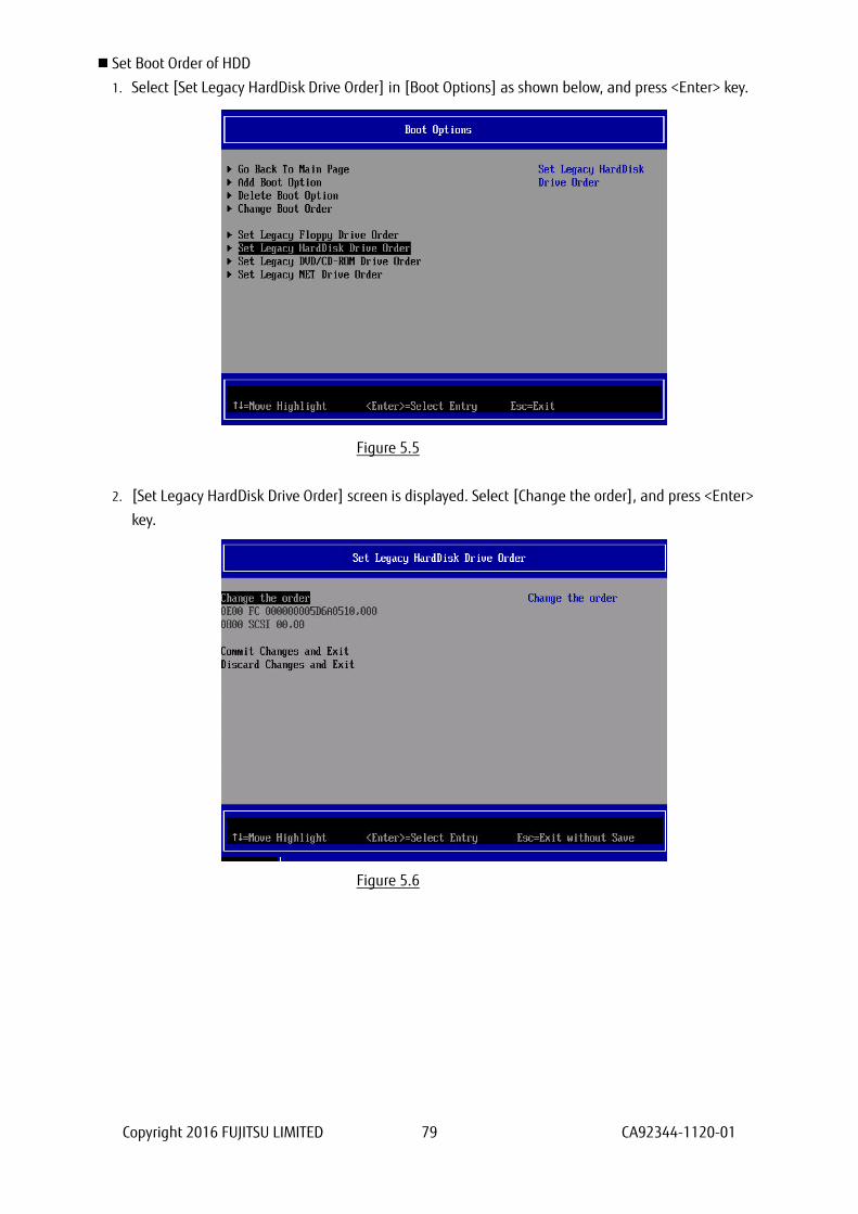
Set Boot Order of HDD
1. Select [Set Legacy HardDisk Drive Order] in [Boot Options] as shown below, and press <Enter> key.
Figure 5.5
2. [Set Legacy HardDisk Drive Order] screen is displayed. Select [Change the order], and press <Enter>
key.
Figure 5.6

Copyright 2016 FUJITSU LIMITED 80 CA92344-1120-01
3. Screen as shown below is displayed. Using [+] key and [-] key, make the SAN Boot device you had
configured to top priority, and press <Enter> key.
Note
Screen samples shown here is in use of English key board. To input [+] key in Japanese key board,
press <Shift> key and [^] key simultaneously.
Figure 5.7
4. If you press <Enter> key, you return to previous screen “Figure 5.6” [Set Legacy HardDisk Drive Order]
screen. In that screen, select [Commit Changes and Exit], and press <Enter> key. Press <Esc> to return
to “Figure 5.3” Boot Manager front page.
Setup of Boot Order is now completed.
Set SAS Disks to be Disabled
1. Open [Change the order] from [Set Legacy HardDisk Drive Order] menu.
2. Move cursor onto SAS disk, and press space key.
3. The SAS disk is made disabled to boot, with being put “//” mark at the beginning of the line of the SAS
disk.
You need to do this setting against all SAS disks.
4. Press <Enter> key to return to previous screen.
5. Select [Commit Changes and Exit] and press <Enter> key.
6. To check if the settings are done correctly, open [Set Legacy HardDisk Drive Order] again.
7. Check following items.
・ All SAS disks are being put “//” mark.
・ In Boot Order, SAN boot disks have higher priority than SAS disks.

Copyright 2016 FUJITSU LIMITED 81 CA92344-1120-01
Figure 5.8
Start Partition and Check Built-in Disk
After you had done settings, reset the partition.
After the partition restarts, do a command shown below to review built-in disks.
# ls –l /dev/disk/by-id
Check if the disks you had added to the system are displayed.
Create Partition in Built-in Disk
Create partitions in built-in disks, and set up filesystems which are, for example, swap filesystems.
You are recommended to create partitions for swap area in built-in disks, not in SAN disks.
For details, please contact the distributor where you purchased your product, or your sales
representative.

Copyright 2016 FUJITSU LIMITED 82 CA92344-1120-01
5.2.5. LUN of other than Boot Disk
In case you use some disks as data disk, not as boot disk, you need to do some settings against ETERNUS
after OS installation.
For detail information on configuring ETERNUS, refer the manuals published in Web site below.
http://www.fujitsu.com/global/support/products/computing/storage/disk/manuals/
5.2.6. Other Case of Using Hard Disk
In case you use devices which are recognized as hard disk in your server, such as USB memory, during you
perform SAN Boot, make them disabled to boot.
For information how to make hard disk disabled to boot, refer “5.2 Using Built-in Disk with Linux”.

Copyright 2016 FUJITSU LIMITED 83 CA92344-1120-01
6. Considerations on Installing VMware
Download the software guide from the web site as shown below.
http://www.fujitsu.com/global/products/computing/servers/mission-critical/primequest/documents/manuals/
To install ESXi, purchase appropriate install media, and install in accordance the software manuals.
Check the install media to know information about hardware compatibilities, such as servers, FC card,
driver, and their version are certified in VMware.

Copyright 2016 FUJITSU LIMITED 84 CA92344-1120-01
PRIMEQUEST 2000 Series
QLogic Fibre Channel Card
SAN Boot Configuration Manual
CA92344-1120-01
April 2016
Published by Fujitsu Limited
● The contents of this document may be changed without a notice for the improvement.
● Our company does not assume responsibility for infringements of patent rights or other rights of
third parties arising on use of the data in this document.
● All rights reserved.