qb50 cubesat msr - university of colorado boulder · •develop a turn-table apparatus for sun...
TRANSCRIPT

QB50 CubeSat MSR
Matt Hong, Nick Andrews, Dylan Cooper, Colin Peterson, Nathan Eckert, Sasanka Bathula, Cole Glommen
Satellite Testbed for Attitude Response
1

Problem StatementDevelop a test suite that will allow for the validation and calibration of the QB50 Attitude Determination and Control System based (ADCS) on simulated mission environment.
2
Project Objectives• Develop an interface board that will allow for a hardware-in-the-
loop simulation by running a simulation on the ADCS board.
• Develop a turn-table apparatus for Sun sensor calibration.
• Develop test apparatus for conducting Helmholtz cage test.

Interface BoardConcept of Operations 1. Send simulation data to
interface board2. Emulate sensor readings
to ADCS board3. Run simulation and log
necessary dataInterface Board Customer ADCSMatlab Simulation
11
1
2
13
Baseline Design
• 4 layer printed circuit board
• PIC microcontroller to program
• Minor changes from CDR
Levels of Success
• Level 3 – Implement GUI to disable sensors
• Communicate at correct frequency• ADCS runs at 10Hz, Simulation runs
much faster• Store simulation data, stream at
desired rate
Critical Project Elements
3
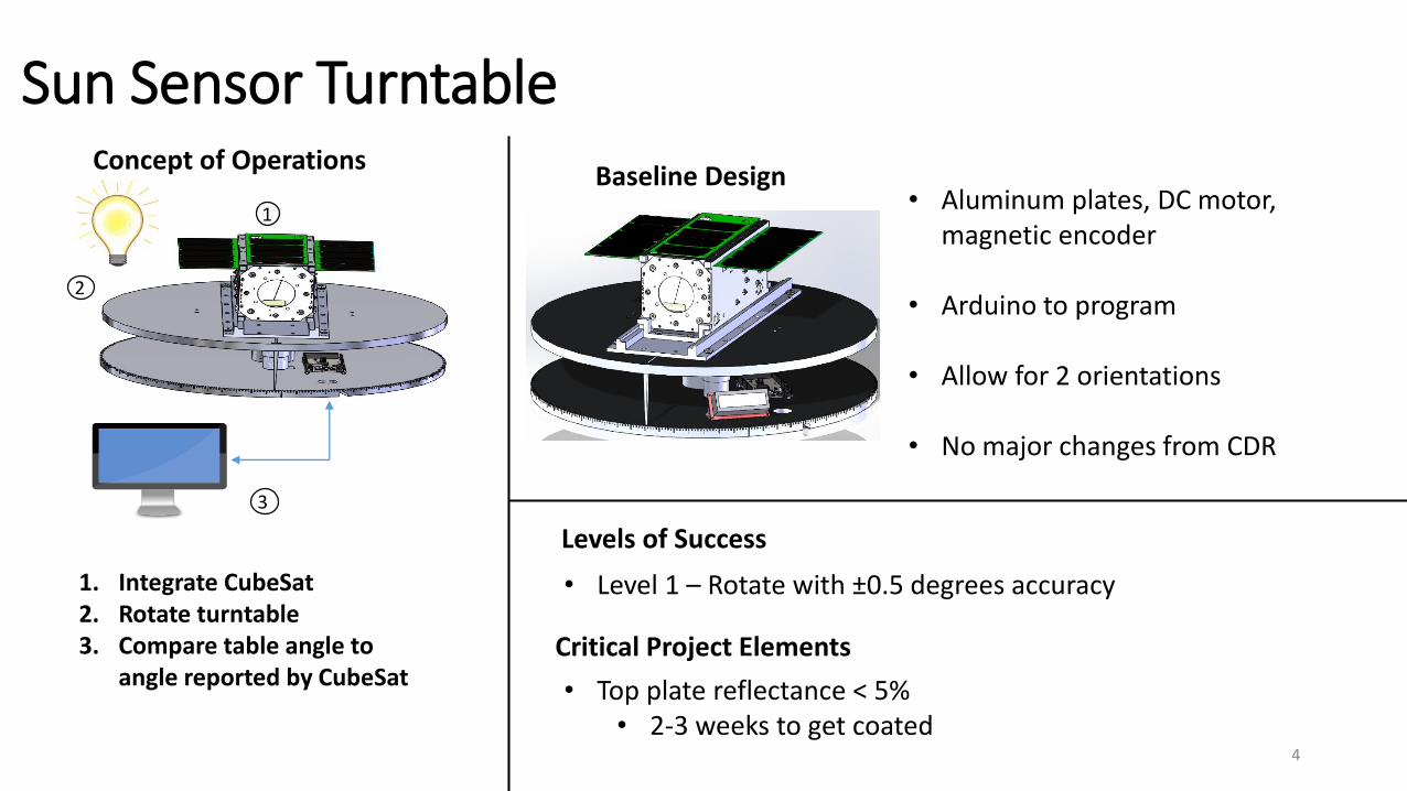
Sun Sensor Turntable
Levels of Success
• Level 1 – Rotate with ±0.5 degrees accuracy
• Top plate reflectance < 5%• 2-3 weeks to get coated
Critical Project Elements
Concept of Operations
1. Integrate CubeSat 2. Rotate turntable3. Compare table angle to
angle reported by CubeSat
11
12
13
Baseline Design• Aluminum plates, DC motor,
magnetic encoder
• Arduino to program
• Allow for 2 orientations
• No major changes from CDR
4

HelmHoltz Cage
Levels of Success
• Level 2 – Verify functionality of magnetorquer
• Minimize torque on line
Critical Project Elements
Concept of Operations
1. Integrate CubeSat 2. Rotate CubeSat without magnetorquer3. Rotate CubeSat with magnetorquer4. Compare results
Baseline Design• Extruded Aluminum
• Braided nylon, 30lbs load
• No major changes from CDR
5

Schedule
6

Interface Board
7
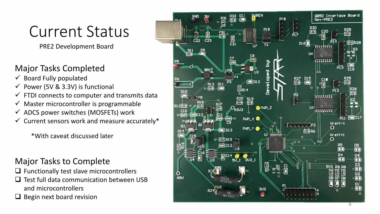
Current StatusPRE2 Development Board
Major Tasks Completed Board Fully populated Power (5V & 3.3V) is functional FTDI connects to computer and transmits data Master microcontroller is programmable ADCS power switches (MOSFETs) work Current sensors work and measure accurately*
Major Tasks to Complete Functionally test slave microcontrollers Test full data communication between USB
and microcontrollers Begin next board revision
*With caveat discussed later
8

Changes to Board
Use of Incorrect I/O pins *
*Found in Errata
Incorrect footprint size
FTDI chip has power enable glitch *
Current sensor power voltage isn’t stable enough
9
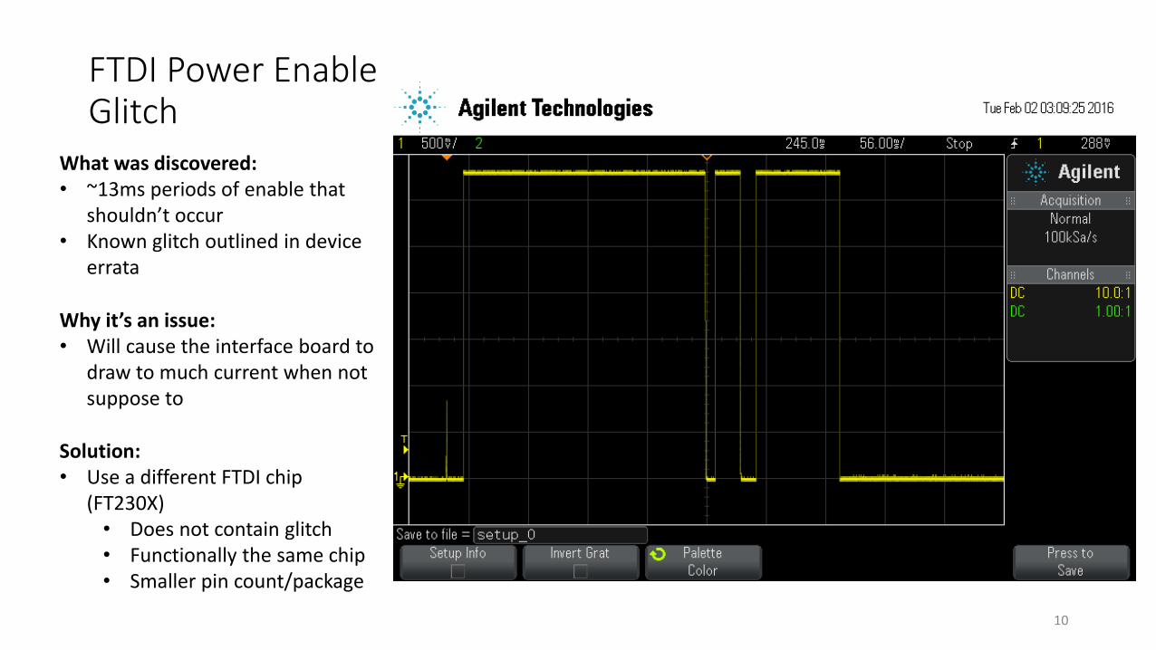
FTDI Power Enable Glitch
What was discovered:• ~13ms periods of enable that
shouldn’t occur• Known glitch outlined in device
errata
Solution:• Use a different FTDI chip
(FT230X)• Does not contain glitch• Functionally the same chip• Smaller pin count/package
Why it’s an issue:• Will cause the interface board to
draw to much current when not suppose to
10

Changes to Board
Use of Incorrect I/O pins *
*Found in Errata
Change base sizes/locations
FTDI chip has power enable glitch *
Current sensors supply voltage isn’t consistent enough
11

Current Sensors
What was known:• Sensors are powered by 5V
• Specified operating range from 4.5V to 5.5V
• Interface board 5V plane varies as much as 300mV depending on load
Solution:• Power sensors with a more
stable 5V (exact method of doing so unknown at this point)
What was discovered:• Sensor measurement output
changes with sensor supply voltage by a ratio of ~1/2
12

Changes to Board
Use of Incorrect I/O pins *
*Found in Errata
Change base sizes/locations
FTDI chip has power enable glitch *
Current sensors supply voltage isn’t consistent enough
13

General Board Layout Changes
• Microcontroller reset button footprints to small
• 2 of 3 LEDs connected to master microcontroller don’t work• Connected to I/O pins
incorrectly labeled as such in datasheet
14

Software Flow Diagram
15

Software Current Status
GUI Interface Built.
FTDI Drivers verifiedWindows 7 and later
D2XX ver. 2.12.12VCP ver 2.12.12
Mac OS X 10.9 and laterD2XX ver 1.2.2VCP ver 1.2.2
Code development under progress for Interface Board testing.
Acquired QB50 Grad Simulation.16

Software Future Work Execute basic test program on Interface board
Development of calibrated magnetometer and gyro models
Compile sun-sensor data.
Transmit simulated sensor data to Interface Board
GUI Implementation
Compute Control Torque from PWM signal
Log Control Torque and Power consumption data.
Full Software system test 17
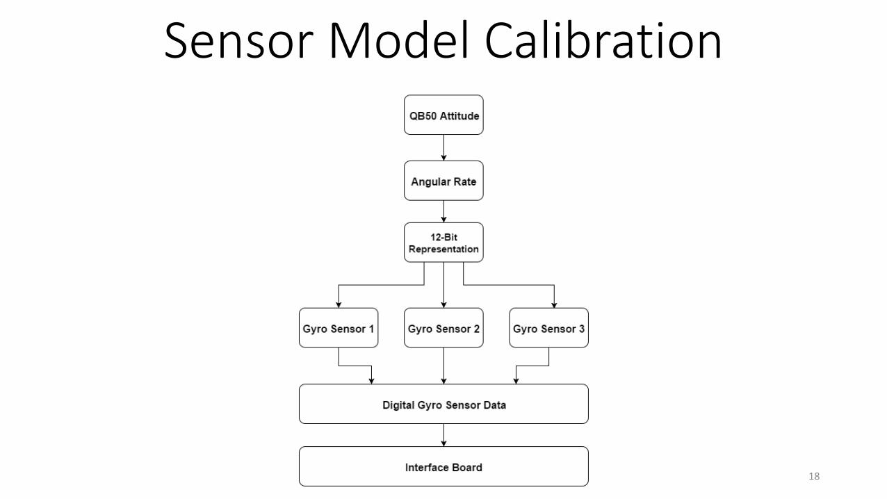
Sensor Model Calibration
18

Sun Sensor Turntable
19

Turntable – Design Update
- Prevent precession of board
- Addition of 4 posts with ball transfers- Ball transfer friction fit into aluminum post
Top board
Bottom board
2.804”
1.125”
Top view
Bearing$10.50 each
20
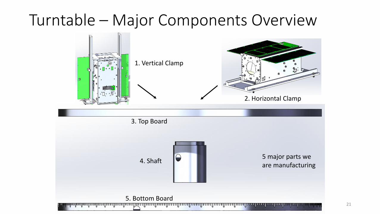
Turntable – Major Components Overview
3. Top Board
4. Shaft
5. Bottom Board
5 major parts we are manufacturing
2. Horizontal Clamp
1. Vertical Clamp
21
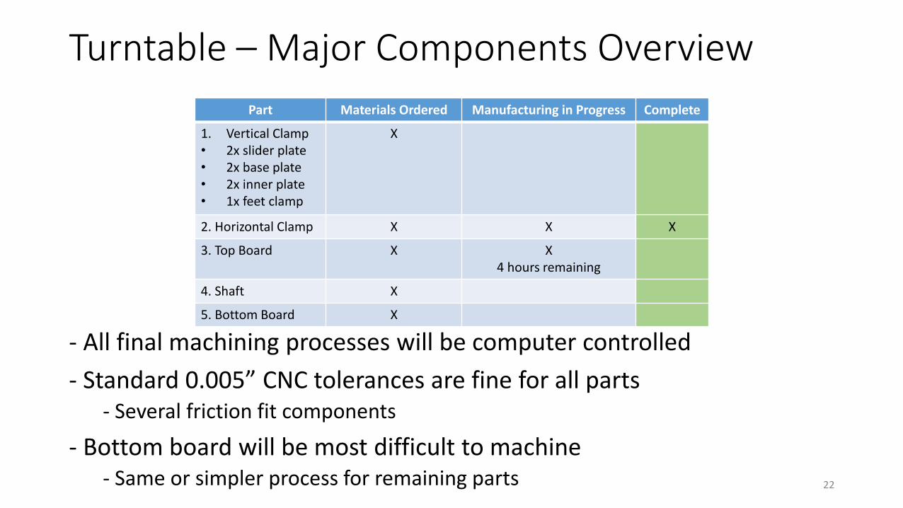
Turntable – Major Components Overview
- All final machining processes will be computer controlled
- Standard 0.005” CNC tolerances are fine for all parts- Several friction fit components
- Bottom board will be most difficult to machine- Same or simpler process for remaining parts
Part Materials Ordered Manufacturing in Progress Complete
1. Vertical Clamp• 2x slider plate• 2x base plate• 2x inner plate• 1x feet clamp
X
2. Horizontal Clamp X X X
3. Top Board X X4 hours remaining
4. Shaft X
5. Bottom Board X
22
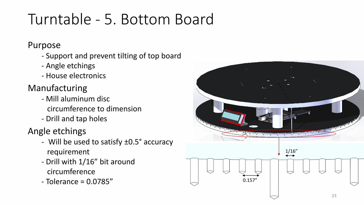
Turntable - 5. Bottom Board
Purpose- Support and prevent tilting of top board- Angle etchings- House electronics
Manufacturing- Mill aluminum disc
circumference to dimension- Drill and tap holes
Angle etchings- Will be used to satisfy ±0.5° accuracy
requirement- Drill with 1/16” bit around
circumference- Tolerance = 0.0785”
1/16”
0.157”
23

Motor
Motor Driver
Encoder
LCD
Current Status
Changes- Arduino Mega to Arduino Due
- 10 bit ADC to 12 bit ADC
Arduino
Turntable – Electronics
12V Power
Ordered Functionally Tested
Performance Tested
LCD X X N/A
Encoder X X
Motor X X
24

HelmHoltz Cage
25

HelCaTS Parts
Parts Purchased (Red) Extruded Aluminum Screws / Nuts Threaded Rod 7.5 ft
2.75 ft ~ 3 ft
~ 2 ft
Parts Provided by Customer (Green) Satellite Helmholtz Cage
Parts Machined by STAR Attachment Cylinders Attachment Plates 26

HelCaTS Purchased Parts
• Various Screws, Nuts, and Clevis Pins ( all aluminum )
• Stainless Steel T-Nuts for attachment to extruded Aluminum• Extruded Aluminum Bars (machined by 8020)
• Cut to size 48” ,45.7”, 33”, 31”, 24” (+/- 0.015”)• Some Ends Tapped• Through holes drilled to pin the sliding mechanism
(location accurate to +/- 0.03 in long direction +/- 0.01 in short direction)
27
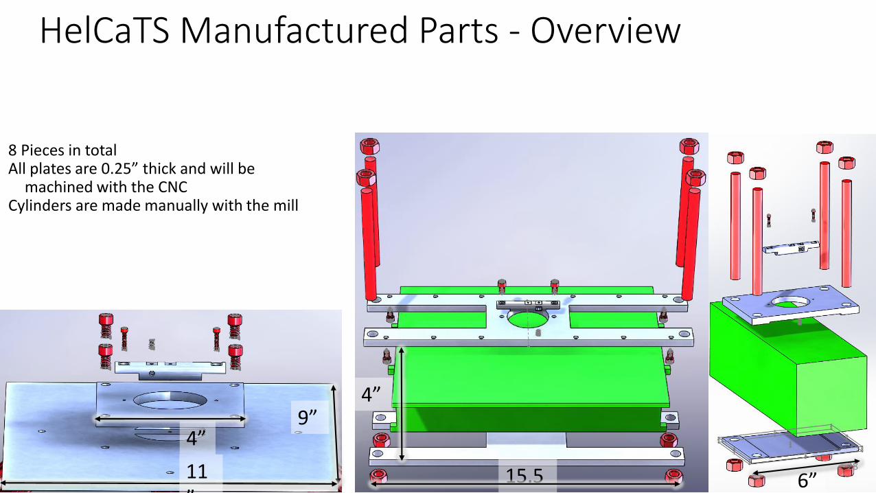
HelCaTS Manufactured Parts - Overview
8 Pieces in totalAll plates are 0.25” thick and will be
machined with the CNCCylinders are made manually with the mill
15.5”
4”
6”
9”
11”
4”28

HelCaTS Manufactured Parts - Overview
Part Materials Ordered
Manufacturing in Progress Complete
1. Small Clamp• Top Plate• Bottom Plate
X x 1 of 2
2. Large Clamp• Top Plate• Bottom Plate
X X
3. Structure Attachment Plates• Big Plate• Small Plate
X
4. Attachment Cylinders X 1 of 2
29
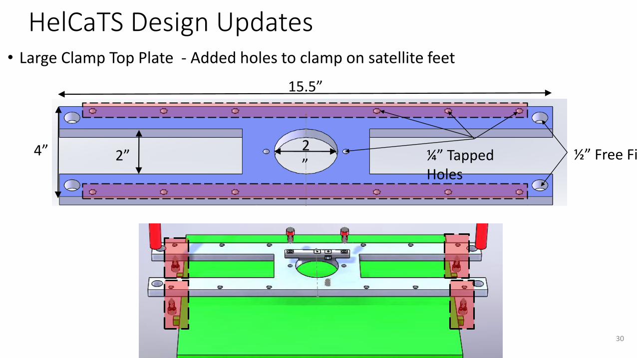
HelCaTS Design Updates• Large Clamp Top Plate - Added holes to clamp on satellite feet
¼” Tapped Holes
½” Free Fit2”
15.5”
4” 2”
30

HelCaTS Design UpdatesAttachment Cylinder – Slotted hole to allow for more tolerance (from 0.001” to 0.0675”)
3” long
4-40 Tapped Hole0.65”
½” Dia. Rod
¼” Free Fit ¼” Free Fit
0.3” wide
31
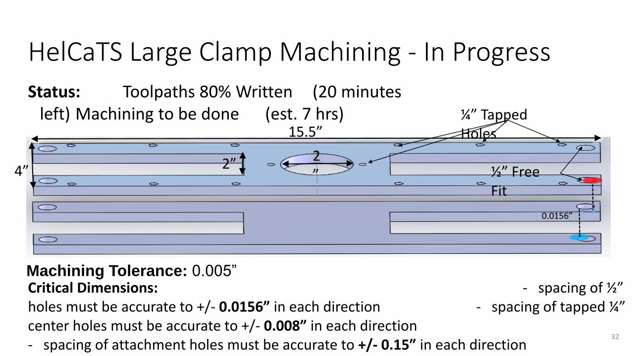
HelCaTS Large Clamp Machining - In Progress
Status: Toolpaths 80% Written (20 minutes left) Machining to be done (est. 7 hrs)
Critical Dimensions: - spacing of ½” holes must be accurate to +/- 0.0156” in each direction - spacing of tapped ¼” center holes must be accurate to +/- 0.008” in each direction - spacing of attachment holes must be accurate to +/- 0.15” in each direction
0.0156”
¼” Tapped Holes
½” Free Fit
2”
15.5”
4” 2”
Machining Tolerance: 0.005”
32
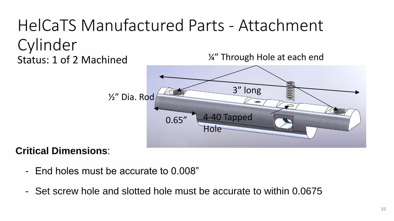
HelCaTS Manufactured Parts - Attachment CylinderStatus: 1 of 2 Machined
3” long
¼” Through Hole at each end
4-40 Tapped Hole
0.65”
½” Dia. Rod
Critical Dimensions:
- End holes must be accurate to 0.008”
- Set screw hole and slotted hole must be accurate to within 0.0675
33

Budget
34

$459.85
$710.74
$1,563.29
$688.37
$1,133.96
$950.30
$800
$1,000
$1,600
$1,000
$1,500
$1,000
$0.00
$200.00
$400.00
$600.00
$800.00
$1,000.00
$1,200.00
$1,400.00
$1,600.00
$1,800.00
Interface Board Sun Sensor Turn Table Helmholtz Cage TestingStructure
Current Total FFR Completion Cost Estimate MSR Completion Cost Estimate Initial Completion Estimate
Budget
• Total Budget: $5,000
• Total Spent: $2,805.77
• FFR Completion Cost Projection: $3,072.63
• MSR Completion Cost Projection: $3,700
• Need: IB revisions
• Δ ≈ +$700 from FFR
• Current EstimatedCompletion Margin: 26%
• FFR Margin Est.: 39%
35
Backup Slides
36
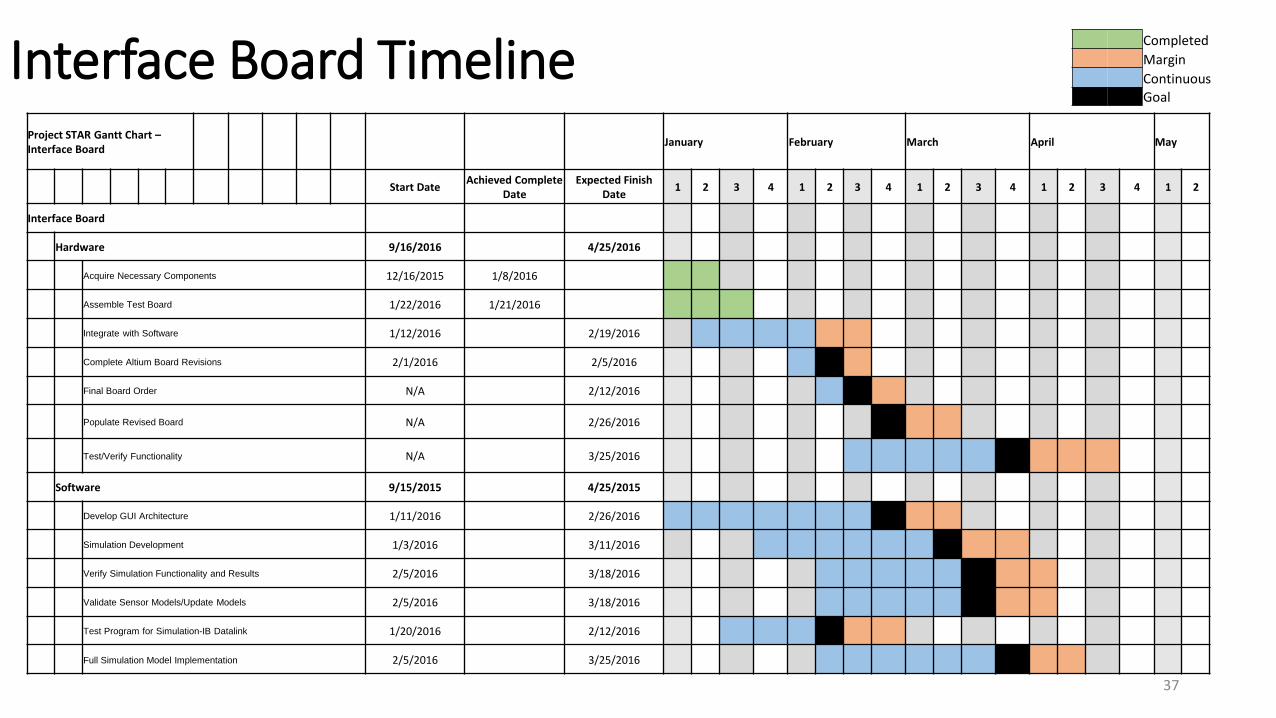
Interface Board TimelineProject STAR Gantt Chart –Interface Board
January February March April May
Start DateAchieved Complete
DateExpected Finish
Date1 2 3 4 1 2 3 4 1 2 3 4 1 2 3 4 1 2
Interface Board
Hardware 9/16/2016 4/25/2016
Acquire Necessary Components 12/16/2015 1/8/2016
Assemble Test Board 1/22/2016 1/21/2016
Integrate with Software 1/12/2016 2/19/2016
Complete Altium Board Revisions 2/1/2016 2/5/2016
Final Board Order N/A 2/12/2016
Populate Revised Board N/A 2/26/2016
Test/Verify Functionality N/A 3/25/2016
Software 9/15/2015 4/25/2015
Develop GUI Architecture 1/11/2016 2/26/2016
Simulation Development 1/3/2016 3/11/2016
Verify Simulation Functionality and Results 2/5/2016 3/18/2016
Validate Sensor Models/Update Models 2/5/2016 3/18/2016
Test Program for Simulation-IB Datalink 1/20/2016 2/12/2016
Full Simulation Model Implementation 2/5/2016 3/25/2016
Completed
Margin
ContinuousGoal
37

Interface Board Status:Hardware
Item Status Next Step
ComponentAcquisition
Complete Order REV0
Soldering Complete Acquire REV0
Header installation
Complete Acquire REV0
PIC MµCProgrammable
Complete Develop code
PIC SµC Programmable
Incomplete Investigate Code Configurator GUI
REV0 Design/Order
Incomplete Continue development
REV0 Population
Incomplete Acquire REV0
38

Interface Board Status:Software for MµC
Item Status Next Step
Switch between compilers (C18 XC8)
Success Continue to use XC8 libraries
#pragma config Success Add more if needed
Initial / Configuration Success Update as needed
Main Loop Success Add in interrupt logic
USART Configuration(Tx/Rx)
In Progress Verify code against hardware
PWM Configuration In Progress Further Develop Code
ADC Configuration In Progress Investigate currentsensors(future slide) 39
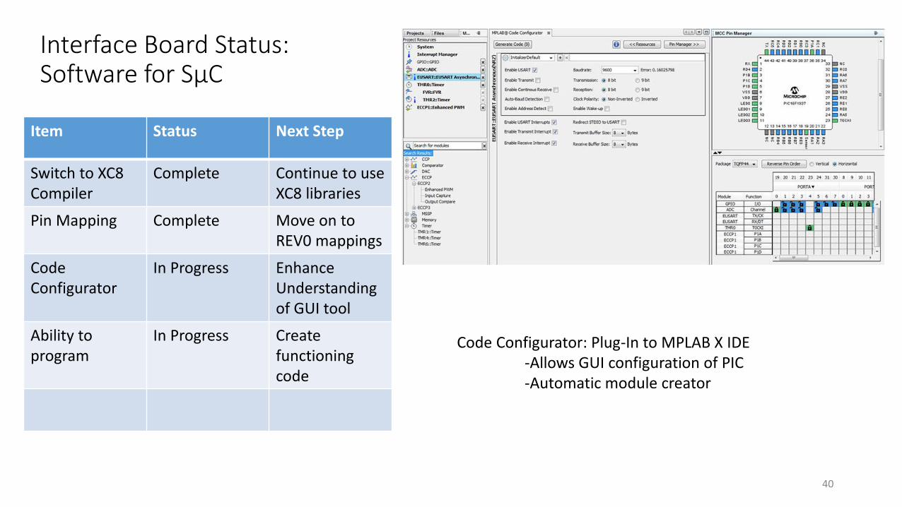
Interface Board Status:Software for SµC
Item Status Next Step
Switch to XC8Compiler
Complete Continue to use XC8 libraries
Pin Mapping Complete Move on to REV0 mappings
Code Configurator
In Progress Enhance Understanding of GUI tool
Ability to program
In Progress Create functioning code
Code Configurator: Plug-In to MPLAB X IDE-Allows GUI configuration of PIC-Automatic module creator
40

Example of Progress – Flashing LEDS
Test Component Hardware/Software
Demonstrating
Board Population Hardware Soldering success
Basic Pin Configuration
Software Pins are mapped correctly
Header Installation Hardware Wires/lines can be probed
PIC can be programmed
Hardware PIC is properly functioning
USB Power Hardware Board has proper power supply
FTDI Chip Hardware Successful communication between the computer and the PIC
41

Power Measurements – PS @ 6.76V
25Ω Load (~400mA total current draw)
• 5V• Power Plane = 5.02V
• A5V = 4.995V
• @ load = 4.993V
• 3.3V• Power Plane = 3.311V
• A3V3 = 3.292V
• @ load = 3.291V
No Load
• 5V• Power Plane = 5.2V
• 3.3V• Power Plane = 3.312V
42

Power Measurements – USB Power
25Ω Load (~400mA total current draw)
• 5V• Power Plane = 4.89V
• A5V = 4.865V
• @ load = 4.860V
• 3.3V• Power Plane = 3.311V
• A3V3 = 3.293V
• @ load = 3.291V
No Load
• 5V• Power Plane = 5.059V
• 3.3V• Power Plane = 3.312V
43

Current Sensor Measurements
• Board powered by power supply, supply voltage was adjusted so that the current sensors always received 5V power
• Measurements taken with Fluke multimeters
• Sensor sensitivity is 185mV/A
• 𝐼 =𝑉𝑂𝑢𝑡−𝑉𝑍𝑒𝑟𝑜
𝑆𝑒𝑛𝑠𝑖𝑡𝑖𝑣𝑖𝑡𝑦
• Currents measured by Fluke• 5V = 204mA
• 3V3 = 139mA
• 0A voltage output• 5V = 2.515V
• 3V3 = 2.51V
• Sensor output under load• 5V = 2.553V → 216mA
• 3V3 = 2.538V → 146mA
44

Turntable - 1. Vertical Clamp
• Purpose• Secure and align CubeSat in vertical orientation
• Status• Material in transit
• Manufacturing• All 5 sub parts made from ¼” thick aluminum plate• Mill aluminum plate and bars to dimension• Drill and tap holes• Bead blast at BioServe lab (decrease reflectance to 15-20%)
• Most difficult component• 1-2 weeks machining
45

1.5”
1/4”
1/4”
1/4”
1/4”
1.5”
1.5”
2.5”
13”
3.268”
3.268”
3.8”
5.5”
Turntable - 1. Vertical Clamp
46
Turntable - 2. Horizontal Clamp
• Purpose• Secure and align CubeSat in horizontal orientation
• Status• Complete
• Manufacturing• Mill aluminum plate to dimension• Drill and tap holes• Bead blast at BioServe lab (decrease reflectance to 15-20%)
• Most difficult component• Manufacturing time
47
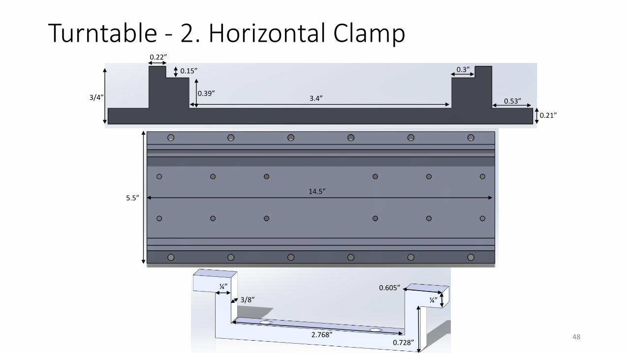
2.768”
3/8”
¼”
0.728”
0.605”
¼”
14.5”5.5”
3/4”
0.22”
0.15”
0.39”3.4”
0.3”
0.21”
0.53”
Turntable - 2. Horizontal Clamp
48
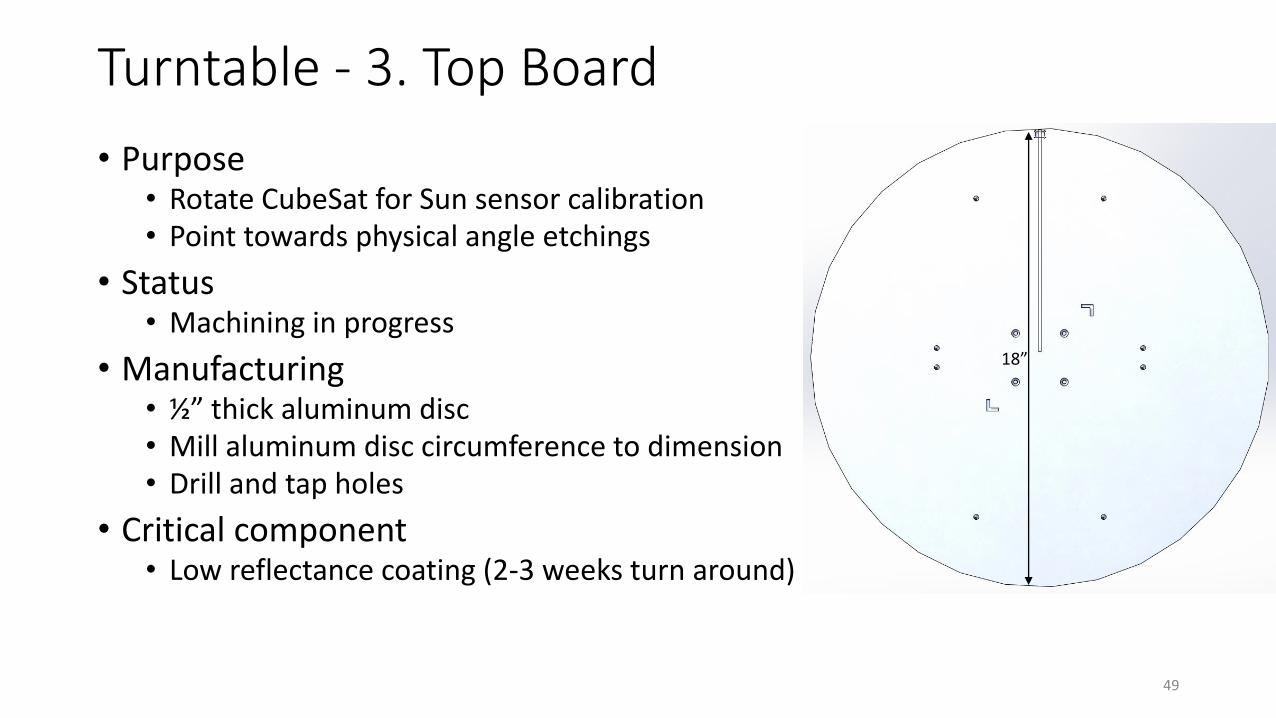
Turntable - 3. Top Board
• Purpose• Rotate CubeSat for Sun sensor calibration• Point towards physical angle etchings
• Status• Machining in progress
• Manufacturing• ½” thick aluminum disc• Mill aluminum disc circumference to dimension• Drill and tap holes
• Critical component• Low reflectance coating (2-3 weeks turn around)
18”
49

Turntable - 4. Shaft
• Purpose• Support load and allow gears to rotate top board• House encoder for angle measurement
• Status• Material in transit
• Manufacturing• Mill aluminum rod
• Encoder housing• Friction fit bearing ring
• Drill and tap holes
• Most difficult component• Manufacturing time (1-2 weeks)
1.75”
0.875”
2.541” 2.791”
0.5”
50

• CG of CubeSat is in 0.4” sphere of geometric center
• Geometric center aligned with rotation axis of board and within diameter of support shaft = no moments produced
• Combination ball-thrust bearing supports axial load• Thrust load capacity = 790 lbs
• Moment load capacity = 430 in*lbs
• Board can roughly support 45 lbs point load on perimeter
Turntable - Force and Moment Analysis
Bottom Board
Support Shaft
Top Board
Bearing
Fthrust = top board + CubeSat + clamp = 21.601 lbs
Rotation axis
2.23”
½”
18”Top Board
BearingEncoder
Shaft gear
½”
2.23”
Wire cutout
Support shaft
51

Turntable - Tolerance Stack Angle Analysis
Max displacement satellite can be from center of board to maintain 0.5° accuracy
18”
Blue = centerRed = displaced position
Yellow = light source
Worst case scenario, assume: - Light source is at perimeter of board,
9” away- Light source is between center and
displaced positions- Distance ‘x’ can be approximated by
isosceles triangle
x
9”9”
0.5°
x
sin(0.25°) = (x/2)/9”
x = 0.0785”Can easily be achieved with 0.005” CNC tolerance
52

Turntable - Sub Parts
These parts require very little or no manufacturing
Part Materials Ordered Manufacturing in Progress Complete
Bearing X ~ X
Shaft gear ~
Motor gear
Precession shafts (4x) X
Precession bearings (4x) ~
Encoder shaft coupling ~
Angle etching needle X
Screws ~
Acrylic spacers ~
Acrylic screws ~
53

HelCaTS Small Clamp Machining – Backup
Status: Top Plate FinishedMachining Order:
- cut out center hole - drill holes - clean outer dimensions - flip over and take down center
6 “
2 “4 “
3.97 “ = 10 cmCritical Dimension:
- spacing of ½” holes must be accurate to 0.0156” in each direction
- spacing of tapped ¼” holes must be accurate to 0.008” in each direction
0.0156”
54

HelCaTS Attachment Plate Machining - To be done
Machining order: - Take out center holes - Drill holes - Clean outer dimensions
Critical Dimensions:- Plate-to-plate holes must be
accurate to 0.008”- ¼” Tapped holes on top plate must
be accurate to 0.1”
9 “
11 “
2 “
¼” TappedHoles
¼” Through Holes
2 “
4 “
4 “
55

HelCaTS Manufactured Parts - Backup
56
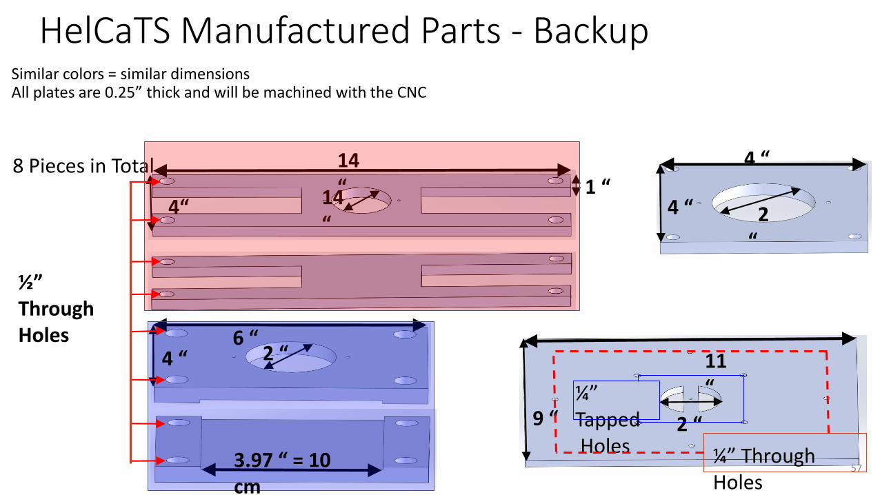
HelCaTS Manufactured Parts - BackupSimilar colors = similar dimensionsAll plates are 0.25” thick and will be machined with the CNC
14 “
4“ 14 “
6 “2 “
9 “
11 “
2 “
2 “
4 “
4 “
4 “
3.97 “ = 10 cm
½” Through Holes
8 Pieces in Total
¼” TappedHoles ¼” Through
Holes
1 “
57

HelCaTS Large Clamp Machining - In Progress
Status: Toolpaths 80% Written (20 minutes left) Machining to be done (est. 7 hrs)
¼” Tapped Holes
½” Free Fit
2”
15.5”
4” 2”
58

HelCaTS Large Clamp Machining
Critical Dimensions: - spacing of ½” holes must be accurate to +/- 0.0156” in each direction
0.0156”
¼” Tapped Holes
½” Free Fit
2”
15.5”
4”
2”
Machining Tolerance: 0.05”
59

HelCaTS Large Clamp Machining
Critical Dimensions: - spacing of tapped ¼” center holes must be accurate to +/- 0.008” in each direction
0.008”
2”
Machining Tolerance: 0.05”
60

HelCaTS Large Clamp Machining - In Progress
Critical Dimensions: - spacing of attachment holes must be accurate to +/- 0.1” in each direction
0.33”
0.375”
61

Tolerance Confirmation - Backup
62

HelCaTS Manufactured Parts - Attachment CylinderStatus: 1 of 2 MachinedMachining Order:
- Mill Shoulders- Make slots for hole drilling- Drill holes- Slot necessary hole
Slotted hole made by: - drilling with a #25 bit (0.1495”)- using a 9/64” end mill (0.1406”) to slot the hole
3” long
¼” Through Hole at each end
4-40 Tapped Hole
0.65”
½” Dia. Rod
63