pxie lebt commissioning...
TRANSCRIPT

PXIE LEBT Commissioning Update
Lionel Prost on behalf of, R. Andrews, K. Carlson, J.-P. Carneiro, R.
D’Arcy, F.G. Garcia, B. Hanna, M. Kucera, A. Saewert, G. Saewert, V. Scarpine, A. Shemyakin, D. Snee, mechanical,
electrical and other technical support
PIP-II Technical Meeting
June 23rd, 2015
Status summary
• Ready to inject beam into the RFQ• After the current shutdown, the beam line as intended for
FY15 will be complete Design of the bend has started
• Continued beam characterization in different modes of operation Ion source tunes
• Preparation for commissioning MULT, measurements procedures…
• Attempts to improve stability Turn on procedure, regulation loops…
2
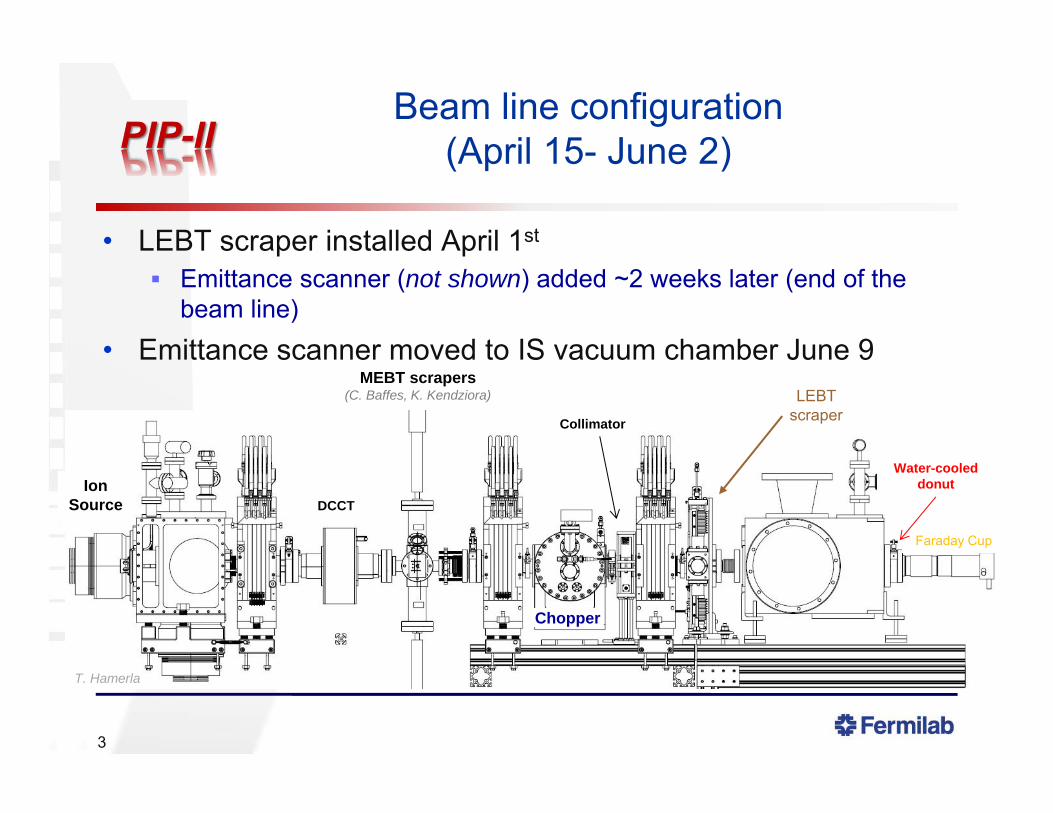
Beam line configuration(April 15- June 2)
• LEBT scraper installed April 1st
Emittance scanner (not shown) added ~2 weeks later (end of the beam line)
• Emittance scanner moved to IS vacuum chamber June 9
3
DCCT
Collimator
Chopper
MEBT scrapers(C. Baffes, K. Kendziora) LEBT
scraper
Faraday Cup
Water-cooled donut
T. Hamerla
Ion Source
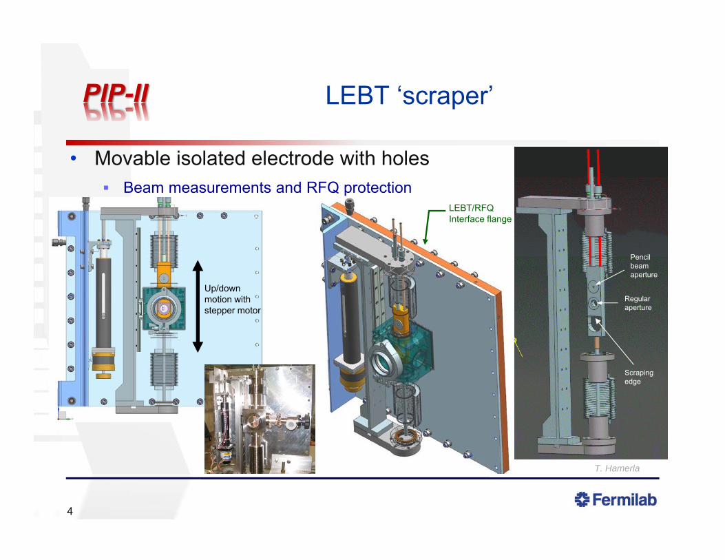
• Movable isolated electrode with holes Beam measurements and RFQ protection
LEBT ‘scraper’
4
LEBT/RFQ Interface flange
Up/down motion with stepper motor
Scraping edge
Pencil beam aperture
Regular aperture
T. Hamerla

Example of profile measurements with LEBT scraper
• LEBT scraper moved over the full range of motion
5
5-mm hole 14-mm hole D-shape hole (edge)
LEB
T sc
rape
r cur
rent
read
bac
k, m
A
mm
Different traces correspond to different vertical displacements of the beam with the Solenoid #3 correctors
Introductory comment
• The beam line configuration shown previously (i.e. with the LEBT scraper installed) does not allow reliable measurements of the beam with the emittance scanner for nominal settings for the RFQ Beam is too large and too diverging
Scraping on emittance scanner ‘clearing electrode’ Emittance scanner range of motion not enough to capture the entire
beam for ‘matched’ conditions
6
Long runs
• Four instances when the beam was left running over the weekend Monitoring from MCR crews No beam interruption all 4 times
Pulsed operation (low duty factor) With studies taking place before and/or after the ‘long runs’, the
beam typically stayed on for more than 80 hours continuously Filament > 700 hours since last change out !!
• Twiss parameters not constant throughout but varied less than from day-to-day operation 10-20% vs. 2-3× (← worst case scenario) Have not established feedback procedure (yet)
Will attempt to use the LEBT scraper current read back
7
1.7
1.8
1.9
2
2.1
2.2
2.3
2.4
2.5
2.6
‐9.5 ‐9 ‐8.5 ‐8 ‐7.5 ‐7
, m
Long runs vs. Day-to-day
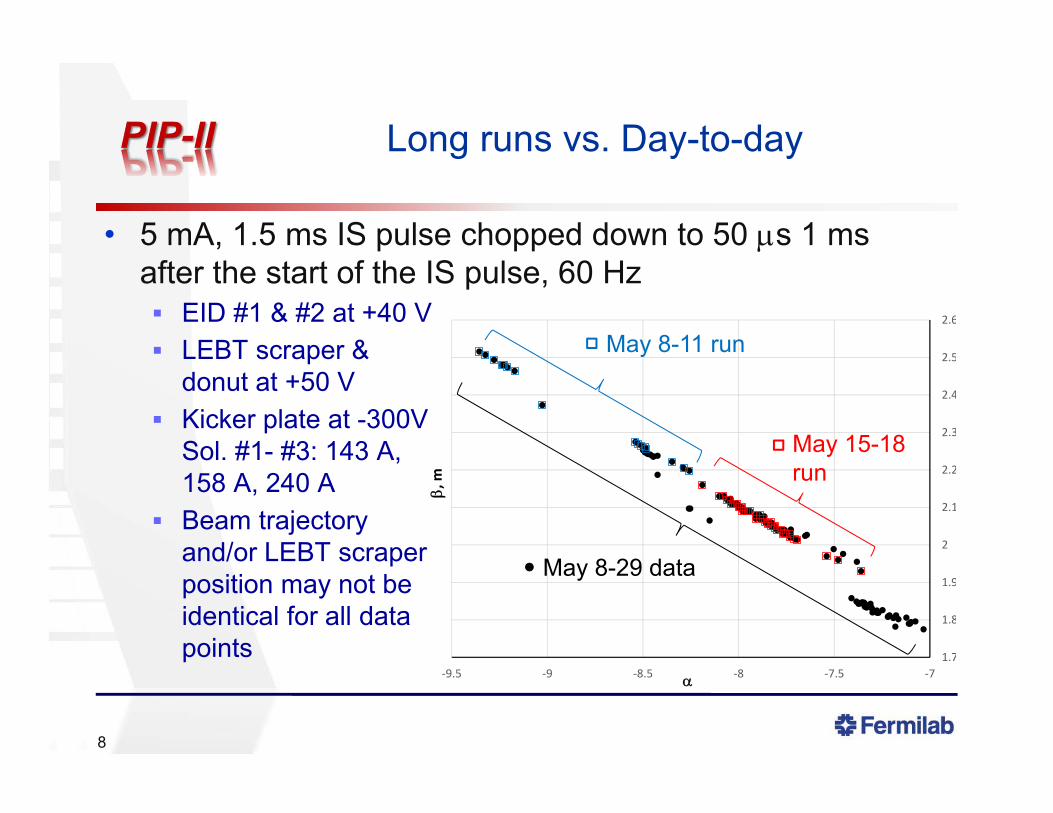
• 5 mA, 1.5 ms IS pulse chopped down to 50 s 1 msafter the start of the IS pulse, 60 Hz EID #1 & #2 at +40 V LEBT scraper &
donut at +50 V Kicker plate at -300V
Sol. #1- #3: 143 A,158 A, 240 A
Beam trajectoryand/or LEBT scraperposition may not beidentical for all datapoints
8
May 8-11 run
May 15-18 run
May 8-29 data

Beam current regulation
9
• Finite State Machine (FSM) adjusts the extraction electrode voltage in order to keep the current read backfrom the DCCT constant
• Does not seem to have anydramatic effect on the beamTwiss parameters stability(positive or negative)• Sensitivity of the beam
parameters to the extractionvoltage is differentdepending on where thenominal voltage lies on theIBeam vs. Vextr. curve (a.k.a.extraction curve)
H2 flow @ HV H2 flow @
ground
0.5 sccm0.5 sccm
0.025 kV0.2 mA
DCCT
Extraction electrode
May 15-18
Summary on beam stability
• Turning on the gas several hours before establishing beam helps maintaining both the beam current and, to a lesser extent, the Twiss parameters more constant Part of the beam parameters variations are likely related to the
gas delivery ‘dynamics’
• Keeping the beam running reduces the variations of the beam parameters In particular, the relatively large variations seen the first few
hours after turning on On the other hand, the beam current regulation loop did not
prevent the beam parameters to wander
10

Position and angle bump MULTs for RFQ transmission tuning
• Using TRACK, Jean-Paul created position & angle bumps “Correctors in solenoidal field” model to take into account the
rotation from solenoid focusing field Accuracy: ~10%
Within measurements errors
• For tuning with RFQ: Center the beam in LEBT
scraper hole, then changethe angle without changingthe position to maximizetransmission
11
y = 0.9733x ‐ 0.198R² = 0.9999
‐6
‐4
‐2
0
2
4
6
‐6 ‐4 ‐2 0 2 4 6
x meas., m
m
x calc., mm
Data from phase space measurements
E.g.: Horizontal MULT
05/28/15
Beam size vs. Solenoid #1 current vs. extraction voltage
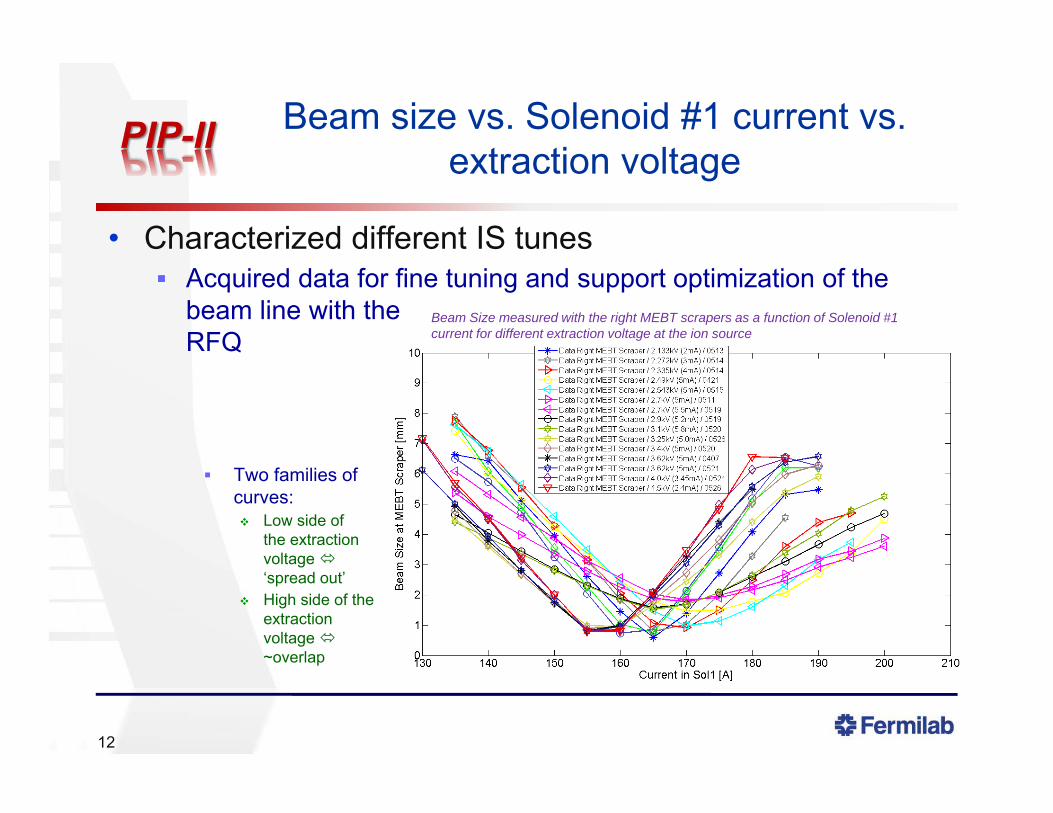
• Characterized different IS tunes Acquired data for fine tuning and support optimization of the
beam line with theRFQ
Two families ofcurves: Low side of
the extractionvoltage ‘spread out’
High side of theextractionvoltage ~overlap
12
Beam Size measured with the right MEBT scrapers as a function of Solenoid #1 current for different extraction voltage at the ion source
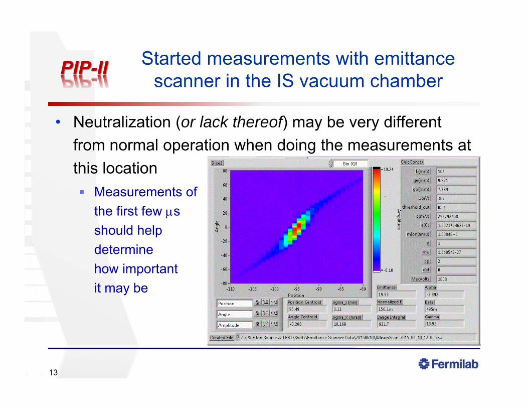
Started measurements with emittance scanner in the IS vacuum chamber
• Neutralization (or lack thereof) may be very different from normal operation when doing the measurements at this location Measurements of
the first few sshould helpdeterminehow importantit may be
13
Current shutdown
• Final configuration before RFQ commissioning Remove MEBT scrapers Install beam stop and vacuum valve Improve alignment of EDI #2 and LEBT scraper
Misalignment of EID #2 determined with beam measurements Replace LEBT scraper bracket, which had to be shimmed
14
Before the RFQ delivery
15
• Test beam stop
• Test Machine Protection System Most hardware has been installed and it is almost ready to go Quite rudimentary at first but designed to be built upon
• Test beam size feedback loop FSM is ready
• Long run in DC mode• Continue measurement of the ion source with the
emittance scanner Possible input for better simulations
Cut-off date for running the LEBT
• July 17, 2015 ~2 weeks before RFQ scheduled delivery for prep work in the
cave E.g.: move cable trays, racks…
Turn off could take place any time once we have verified beam operation following this shutdown Will take more time for measurements if given to us… i.e. RFQ
delivery delays
16

17
Additional slides

Role of LEBT in PXIE
• Prepare beam for RFQ (i.e. , ) and machine protection• DC operation
5 mA, reliable and ‘stable’ n,rms ≤ 0.18 mm mrad
Uncontrolled losses <10%
• Pulse operation 1-16667 s, 60 Hz Twiss functions representative of DC beam operation
To transition from short pulse (commissioning) to DC (normal operation) If not the same, DC Twiss functions should be predictable from short pulse
measurements
18
Beam dumpHEBTMEBTRFQLEBTIon
Source HW & SSR1
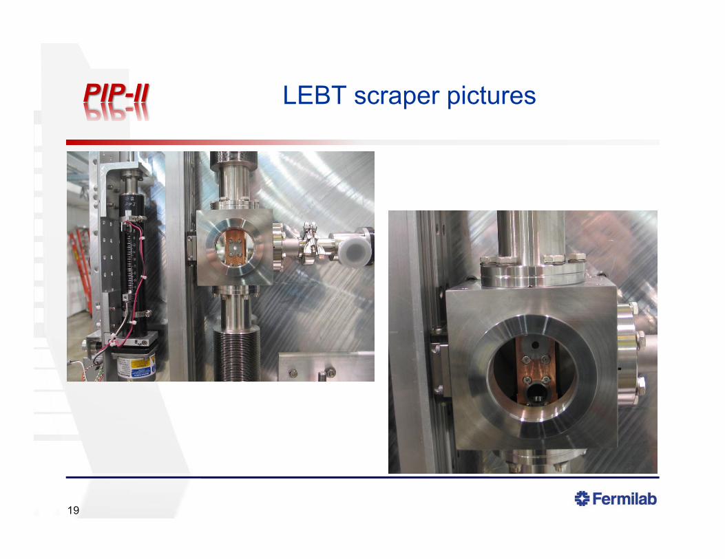
LEBT scraper pictures
19
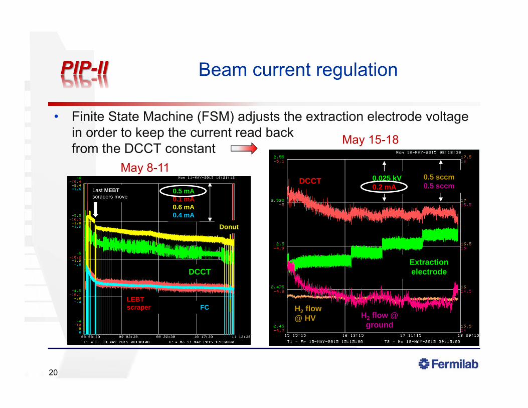
Beam current regulation
20
• Finite State Machine (FSM) adjusts the extraction electrode voltage in order to keep the current read backfrom the DCCT constant
H2 flow @ HV H2 flow @
ground
0.5 sccm0.5 sccm
0.025 kV0.2 mA
DCCT
Extraction electrode
May 15-18
Donut
0.5 mA0.1 mA0.6 mA0.4 mA
FCLEBT scraper
DCCT
Last MEBTscrapers move
May 8-11

Beam sensitivity to H2 flow
• Part of the beam parameters variations are likely related to the gas delivery ‘dynamics’ Turning on the gas several hours
before establishing beam helpsmaintaining both the beamcurrent and, to a lesser extent,the Twiss parameters moreconstant The filament does not need
to be on i.e. not a thermaleffect
21
10-5 torr10-6 torr0.5 sccm
H2 flow
IS US IG
IS DS IG
~5 h
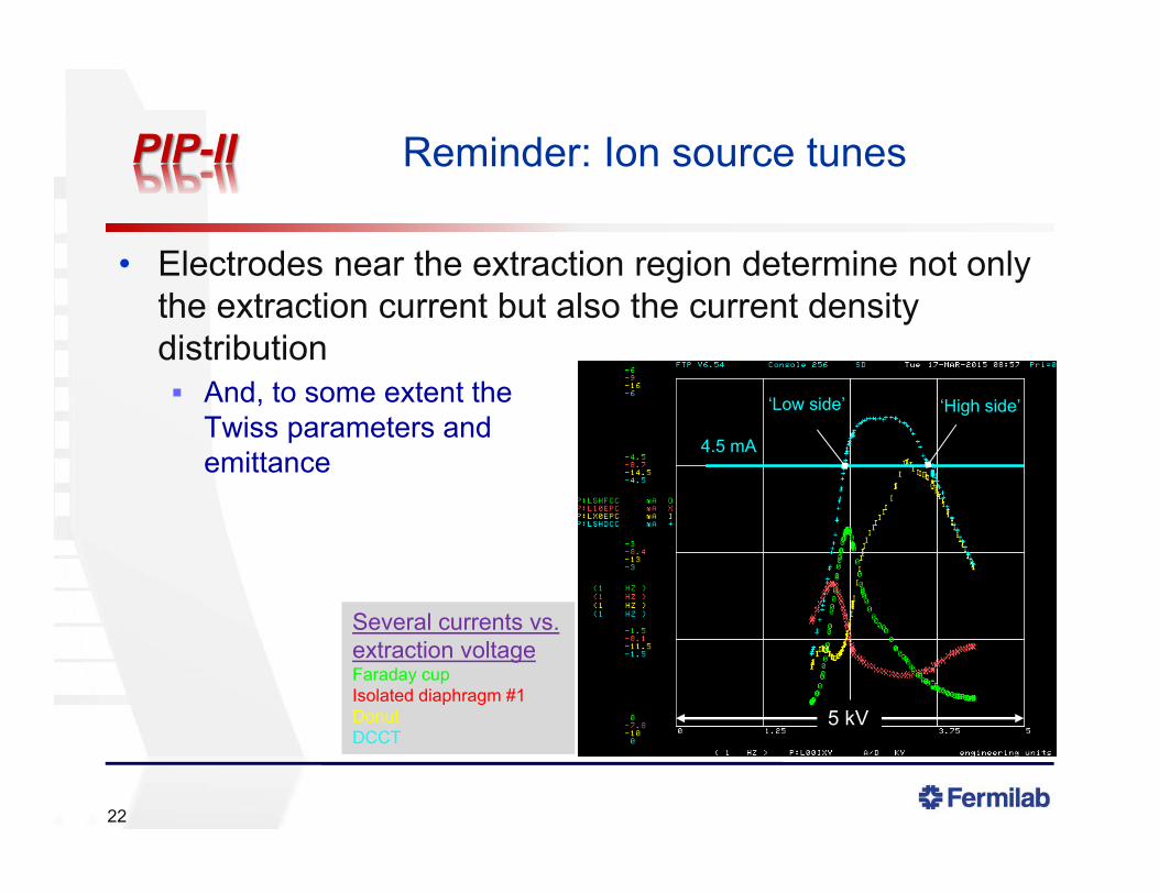
Reminder: Ion source tunes
• Electrodes near the extraction region determine not only the extraction current but also the current density distribution And, to some extent the
Twiss parameters andemittance
22
Several currents vs. extraction voltageFaraday cupIsolated diaphragm #1DonutDCCT
4.5 mA
‘Low side’ ‘High side’
5 kV