pws4205, pws4305, pws4323, pws4602, and pws4721kinear dc power supplies
TRANSCRIPT

xx
PWS4205, PWS4305, PWS4323, PWS4602, and PWS4721Linear DC Power Supplies
ZZZ
Programmer Manual
*P077048102*
077-0481-02


PWS4205, PWS4305, PWS4323, PWS4602, and PWS4721Linear DC Power Supplies
ZZZ
Programmer Manual
xx
www.tektronix.com077-0481-02

Copyright © Tektronix, Inc. All rights reserved.
Tektronix products are covered by U.S. and foreign patents, issued and pending. Information in this publicationsupersedes that in all previously published material. Specifications and price change privileges reserved.
Tektronix, Inc., P.O. Box 500, Beaverton, OR 97077
TEKTRONIX and TEK are registered trademarks of Tektronix, Inc.
Contacting Tektronix
Tektronix, Inc.14150 SW Karl Braun DriveP.O. Box 500Beaverton, OR 97077USA
For product information, sales, service, and technical support:In North America, call 1-800-833-9200.Worldwide, visit www.tektronix.com to find contacts in your area.

Table of Contents
Preface .. . . . . . . . . . . . . . . . . . . . . . . . . . . . . . . . . . . . . . . . . . . . . . . . . . . . . . . . . . . . . . . . . . . . . . . . . . . . . . . . . . . . . . . . . . . . . . . . . . . . . . . . . . . . . iii
Getting StartedGetting Started . . . . . . . . . . . . . . . . . . . . . . . . . . . . . . . . . . . . . . . . . . . . . . . . . . . . . . . . . . . . . . . . . . . . . . . . . . . . . . . . . . . . . . . . . . . . . . . . . . . . 1-1
Using the USB .. . . . . . . . . . . . . . . . . . . . . . . . . . . . . . . . . . . . . . . . . . . . . . . . . . . . . . . . . . . . . . . . . . . . . . . . . . . . . . . . . . . . . . . . . . . . . . 1-1Using the GPIB .. . . . . . . . . . . . . . . . . . . . . . . . . . . . . . . . . . . . . . . . . . . . . . . . . . . . . . . . . . . . . . . . . . . . . . . . . . . . . . . . . . . . . . . . . . . . . 1-1Command Timing. . . . . . . . . . . . . . . . . . . . . . . . . . . . . . . . . . . . . . . . . . . . . . . . . . . . . . . . . . . . . . . . . . . . . . . . . . . . . . . . . . . . . . . . . . . . 1-2
Command Syntax.. . . . . . . . . . . . . . . . . . . . . . . . . . . . . . . . . . . . . . . . . . . . . . . . . . . . . . . . . . . . . . . . . . . . . . . . . . . . . . . . . . . . . . . . . . . . . . . . 2-1Command and Query Structure . . . . . . . . . . . . . . . . . . . . . . . . . . . . . . . . . . . . . . . . . . . . . . . . . . . . . . . . . . . . . . . . . . . . . . . . . . . . 2-1Command Entry. . . . . . . . . . . . . . . . . . . . . . . . . . . . . . . . . . . . . . . . . . . . . . . . . . . . . . . . . . . . . . . . . . . . . . . . . . . . . . . . . . . . . . . . . . . . . . 2-3
Command Groups . . . . . . . . . . . . . . . . . . . . . . . . . . . . . . . . . . . . . . . . . . . . . . . . . . . . . . . . . . . . . . . . . . . . . . . . . . . . . . . . . . . . . . . . . . . . . . . . 2-7Status Commands. . . . . . . . . . . . . . . . . . . . . . . . . . . . . . . . . . . . . . . . . . . . . . . . . . . . . . . . . . . . . . . . . . . . . . . . . . . . . . . . . . . . . . . . . . . . 2-7Save and Recall Commands . . . . . . . . . . . . . . . . . . . . . . . . . . . . . . . . . . . . . . . . . . . . . . . . . . . . . . . . . . . . . . . . . . . . . . . . . . . . . . . . 2-8System Commands . . . . . . . . . . . . . . . . . . . . . . . . . . . . . . . . . . . . . . . . . . . . . . . . . . . . . . . . . . . . . . . . . . . . . . . . . . . . . . . . . . . . . . . . . . 2-8Diagnostic Commands . . . . . . . . . . . . . . . . . . . . . . . . . . . . . . . . . . . . . . . . . . . . . . . . . . . . . . . . . . . . . . . . . . . . . . . . . . . . . . . . . . . . . . 2-9Synchronization Commands. . . . . . . . . . . . . . . . . . . . . . . . . . . . . . . . . . . . . . . . . . . . . . . . . . . . . . . . . . . . . . . . . . . . . . . . . . . . . . . . 2-9Trigger Commands . . . . . . . . . . . . . . . . . . . . . . . . . . . . . . . . . . . . . . . . . . . . . . . . . . . . . . . . . . . . . . . . . . . . . . . . . . . . . . . . . . . . . . . . . . 2-9Measurement Commands .. . . . . . . . . . . . . . . . . . . . . . . . . . . . . . . . . . . . . . . . . . . . . . . . . . . . . . . . . . . . . . . . . . . . . . . . . . . . . . . . 2-10Source Commands.. . . . . . . . . . . . . . . . . . . . . . . . . . . . . . . . . . . . . . . . . . . . . . . . . . . . . . . . . . . . . . . . . . . . . . . . . . . . . . . . . . . . . . . . 2-10Bus Command Group .. . . . . . . . . . . . . . . . . . . . . . . . . . . . . . . . . . . . . . . . . . . . . . . . . . . . . . . . . . . . . . . . . . . . . . . . . . . . . . . . . . . . 2-11
Commands Listed in Alphabetical Order . . . . . . . . . . . . . . . . . . . . . . . . . . . . . . . . . . . . . . . . . . . . . . . . . . . . . . . . . . . . . . . . . . . . 2-13
Status and EventsStatus and Events . . . . . . . . . . . . . . . . . . . . . . . . . . . . . . . . . . . . . . . . . . . . . . . . . . . . . . . . . . . . . . . . . . . . . . . . . . . . . . . . . . . . . . . . . . . . . . . . . 3-1
Status Reporting Structure . . . . . . . . . . . . . . . . . . . . . . . . . . . . . . . . . . . . . . . . . . . . . . . . . . . . . . . . . . . . . . . . . . . . . . . . . . . . . . . . . . 3-1Registers . . . . . . . . . . . . . . . . . . . . . . . . . . . . . . . . . . . . . . . . . . . . . . . . . . . . . . . . . . . . . . . . . . . . . . . . . . . . . . . . . . . . . . . . . . . . . . . . . . . . . . 3-3Queues . . . . . . . . . . . . . . . . . . . . . . . . . . . . . . . . . . . . . . . . . . . . . . . . . . . . . . . . . . . . . . . . . . . . . . . . . . . . . . . . . . . . . . . . . . . . . . . . . . . . . . . . 3-8Messages and Codes.. . . . . . . . . . . . . . . . . . . . . . . . . . . . . . . . . . . . . . . . . . . . . . . . . . . . . . . . . . . . . . . . . . . . . . . . . . . . . . . . . . . . . . . . 3-8
AppendicesAppendix A: ASCII Code Chart . . . . . . . . . . . . . . . . . . . . . . . . . . . . . . . . . . . . . . . . . . . . . . . . . . . . . . . . . . . . . . . . . . . . . . . . . . . . . . . A-1Appendix B: Programming Examples. . . . . . . . . . . . . . . . . . . . . . . . . . . . . . . . . . . . . . . . . . . . . . . . . . . . . . . . . . . . . . . . . . . . . . . . . B-1Appendix C: Default Setup . . . . . . . . . . . . . . . . . . . . . . . . . . . . . . . . . . . . . . . . . . . . . . . . . . . . . . . . . . . . . . . . . . . . . . . . . . . . . . . . . . . . . C-1
PWS4205, PWS4305, PWS4323, PWS4602, and PWS4721 Power Supply Programmer Manual i

Table of Contents
ii PWS4205, PWS4305, PWS4323, PWS4602, and PWS4721 Power Supply Programmer Manual

PrefaceThis programmer manual provides commands, and explains the use of thosecommands, for remotely controlling the PWS4205, PWS4305, PWS4323,PWS4602, and the PWS4721 Linear DC Power Supplies. With this information,you can write computer programs to perform functions, such as setting thecontrols, taking measurements, performing statistical calculations, and exportingdata for use in other programs.
PWS4205, PWS4305, PWS4323, PWS4602, and PWS4721 Power Supply Programmer Manual iii

Preface
iv PWS4205, PWS4305, PWS4323, PWS4602, and PWS4721 Power Supply Programmer Manual

Getting Started


Getting StartedYour power supply has a USB 2.0 high-speed device port to control the powersupply using the USBTMC protocol. The USBTMC protocol allows USB devicesto communicate using IEEE-488.2 style messages.
You can also remotely communicate between your power supply and PC overGPIB using the TEK-USB-488 Adapter.
Using the USBStart by connecting an appropriate USB cable between the USB 2.0 high-speeddevice port on the rear panel of your power supply and a PC.
In order for the PC to recognize the power supply, a USBTMC driver must beinstalled on the PC. A USBTMC driver can be installed on your PC by installing avirtual instrument communications API like TekVISA or NIVISA. These VISAsare available for download from the Tektronix or National Instruments Web sites.Once the USBTMC driver is loaded, your PC will establish communication withthe power supply upon USB cable connection.
For further remote control and/or programming use, other software applicationsmay be needed in addition to a VISA and the USBTMC driver.
Using the GPIBStart by connecting an appropriate USB cable between the USB 2.0 high-speeddevice port on the rear panel of your power supply and the TEK-USB-488Adapter host port. Then connect a GPIB cable from the TEK-USB-488 Adapterto your PC.
Supply power to the adapter in one of the following ways:
Use an optional 5 V DC power adapter connected to the 5 V DC powerinput on the adapter.
Use an appropriate USB cable connected to a powered USB host port on yourPC and the device port on the TEK-USB-488 Adapter.
GPIB Requirements Before setting up the power supply for remote communication using the electronic(physical) GPIB interface, you should familiarize yourself with the followingrecommendations:
PWS4205, PWS4305, PWS4323, PWS4602, and PWS4721 Power Supply Programmer Manual 1-1

Getting Started
A unique device address should be assigned to each device on the bus. Notwo devices should share the same device address.
No more than 15 devices can be connected to any one bus.
Only one device should be connected for every 6 feet (2 meters) of cable used.
No more than 65 feet (20 meters) of cable should be used to connect devicesto a bus.
At least two-thirds of the devices on the network should be on while usingthe network.
Connect the devices on the network in a star or linear configuration. Do notuse loop or parallel configurations.
To Change GPIB AddressSettings
Your power supply must have a unique device address to function properly. Thedefault setting for the GPIB configuration is GPIB Address 1. If there is morethan one GPIB instrument on the bus, you will need to change the default settingon the power supply. To change the GPIB address settings, do the following:
1. On the instrument front-panel, push the Shift button and then the 1 button toaccess the menu.
2. Press the down arrow key until you see System and then press the Enterbutton.
3. Press the down arrow key until you see Address and then press the Enterbutton.
4. You can now change the address of your GPIB port. This will set the GPIBaddress on an attached TEK-USB-488 Adapter.
The power supply is now set up for bidirectional communication with yourcontroller.
Command TimingThe average time it takes to both send and receive every command isapproximately 20 ms. In the case of more complex commands, more time maybe required to complete transmission.
1-2 PWS4205, PWS4305, PWS4323, PWS4602, and PWS4721 Power Supply Programmer Manual

Command SyntaxYou can control the power supply through the USB interface using commandsand queries.
This section describes the syntax these commands and queries use and theconventions the power supply uses to process them. The commands and queriesthemselves are listed by group and alphabetically. (See page 2-7, CommandGroups.)
You transmit commands to the power supply using the enhanced AmericanStandard Code for Information Interchange (ASCII) character encoding. AppendixA contains a chart of the ASCII character set.
The Backus Naur Form (BNF) notation is used in this manual to describecommands and queries. (See Table 2-1.)
Table 2-1: BNF notationSymbol Meaning< > Defined element::= Is defined as| Exclusive OR{ } Group; one element is required[ ] Optional; can be omitted. . . Previous element(s) may be repeated( ) Comment
Command and Query StructureCommands consist of set commands and query commands (usually simply calledcommands and queries). Commands change power supply settings or perform aspecific action. Queries cause the power supply to return data and informationabout its status.
Most commands have both a set form and a query form. The query form of thecommand is the same as the set form except that it ends with a question mark.For example, the set command STATus:OPERation:ENAble has a query formSTATus:OPERation:ENAble?. Not all commands have both a set and a queryform; some commands are set only and some are query only.
A command message is a command or query name, followed by any informationthe power supply needs to execute the command or query. Command messagesconsist of five different element types. (See Table 2-3.)
PWS4205, PWS4305, PWS4323, PWS4602, and PWS4721 Power Supply Programmer Manual 2-1
Command Syntax
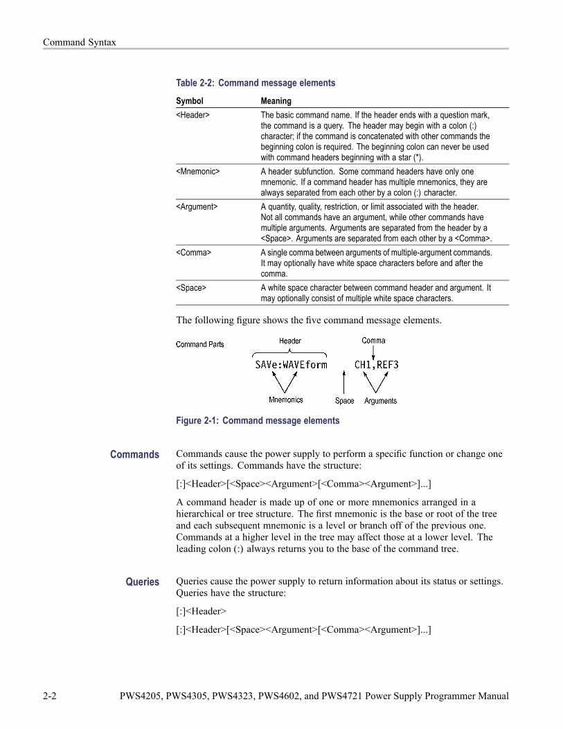
Table 2-2: Command message elementsSymbol Meaning<Header> The basic command name. If the header ends with a question mark,
the command is a query. The header may begin with a colon (:)character; if the command is concatenated with other commands thebeginning colon is required. The beginning colon can never be usedwith command headers beginning with a star (*).
<Mnemonic> A header subfunction. Some command headers have only onemnemonic. If a command header has multiple mnemonics, they arealways separated from each other by a colon (:) character.
<Argument> A quantity, quality, restriction, or limit associated with the header.Not all commands have an argument, while other commands havemultiple arguments. Arguments are separated from the header by a<Space>. Arguments are separated from each other by a <Comma>.
<Comma> A single comma between arguments of multiple-argument commands.It may optionally have white space characters before and after thecomma.
<Space> A white space character between command header and argument. Itmay optionally consist of multiple white space characters.
The following figure shows the five command message elements.
Figure 2-1: Command message elements
Commands Commands cause the power supply to perform a specific function or change oneof its settings. Commands have the structure:
[:]<Header>[<Space><Argument>[<Comma><Argument>]...]
A command header is made up of one or more mnemonics arranged in ahierarchical or tree structure. The first mnemonic is the base or root of the treeand each subsequent mnemonic is a level or branch off of the previous one.Commands at a higher level in the tree may affect those at a lower level. Theleading colon (:) always returns you to the base of the command tree.
Queries Queries cause the power supply to return information about its status or settings.Queries have the structure:
[:]<Header>
[:]<Header>[<Space><Argument>[<Comma><Argument>]...]
2-2 PWS4205, PWS4305, PWS4323, PWS4602, and PWS4721 Power Supply Programmer Manual

Command Syntax
You can specify a query command at any level within the command tree unlessotherwise noted. These branch queries return information about all the mnemonicsbelow the specified branch or level.
Query Responses When a query is sent to the power supply, only the values are returned. Whenthe returned value is a mnemonic, it is noted in abbreviated format, as shownin the following table.
Table 2-3: Query response examplesQuery ResponseMEASure:VOLTage:DC? 5.0011SOURce:FUNCtion:MODE? LIST
Command EntryFollow these general rules when entering commands:
Enter commands in upper or lower case.
You can precede any command with white space characters. White spacecharacters include any combination of the ASCII control characters 00 through09 and 0B through 20 hexadecimal (0 through 9 and 11 through 32 decimal).
The power supply ignores commands that consists of just a combination ofwhite space characters and line feeds.
SCPI Commands andQueries
The power supply uses a command language based on the SCPI standard. TheSCPI (Standard Commands for Programmable Instruments) standard was createdby a consortium to provide guidelines for remote programming of instruments.These guidelines provide a consistent programming environment for instrumentcontrol and data transfer. This environment uses defined programming messages,instrument responses and data formats that operate across all SCPI instruments,regardless of manufacturer.
The SCPI language is based on a hierarchical or tree structure that represents asubsystem. The top level of the tree is the root node; it is followed by one or morelower-level nodes. (See Figure 2-2.)
Figure 2-2: Example of SCPI subsystem hierarchy tree
PWS4205, PWS4305, PWS4323, PWS4602, and PWS4721 Power Supply Programmer Manual 2-3
Command Syntax
You can create commands and queries from these subsystem hierarchy trees.Commands specify actions for the instrument to perform. Queries returnmeasurement data and information about parameter settings.
Message Terminators This manual uses the term <EOM> (End of message) to represent a messageterminator.
USB End of Message (EOM) terminators. See the USB Test and MeasurementClass Specification (USBTMC) section 3.2.1 for details. The power supplyterminates messages by setting the EOM bit in the USB header of the lasttransfer of a message to the host (USBTMC Specification section 3.3.1), and byterminating messages with a LF.
When receiving, the power supply expects a LF and an asserted EOM bit asa message terminator.
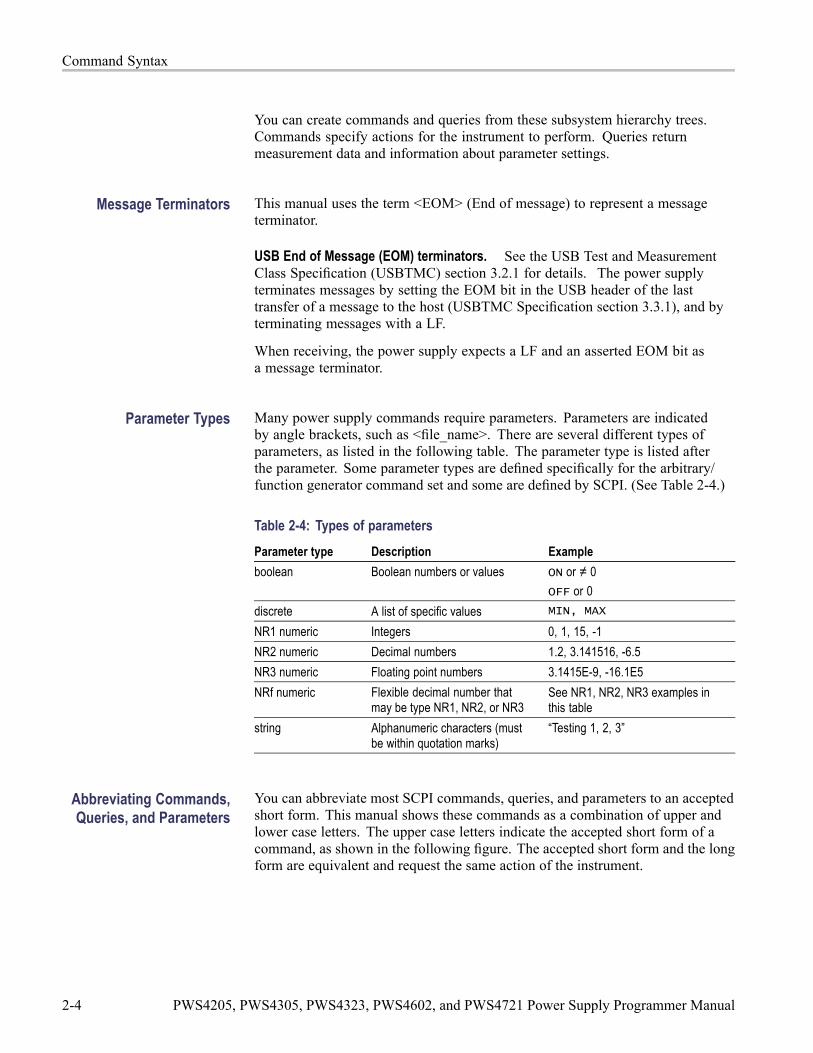
Parameter Types Many power supply commands require parameters. Parameters are indicatedby angle brackets, such as <file_name>. There are several different types ofparameters, as listed in the following table. The parameter type is listed afterthe parameter. Some parameter types are defined specifically for the arbitrary/function generator command set and some are defined by SCPI. (See Table 2-4.)
Table 2-4: Types of parametersParameter type Description Exampleboolean Boolean numbers or values ON or ≠ 0
OFF or 0discrete A list of specific values MIN, MAX
NR1 numeric Integers 0, 1, 15, -1NR2 numeric Decimal numbers 1.2, 3.141516, -6.5NR3 numeric Floating point numbers 3.1415E-9, -16.1E5NRf numeric Flexible decimal number that
may be type NR1, NR2, or NR3See NR1, NR2, NR3 examples inthis table
string Alphanumeric characters (mustbe within quotation marks)
“Testing 1, 2, 3”
Abbreviating Commands,Queries, and Parameters
You can abbreviate most SCPI commands, queries, and parameters to an acceptedshort form. This manual shows these commands as a combination of upper andlower case letters. The upper case letters indicate the accepted short form of acommand, as shown in the following figure. The accepted short form and the longform are equivalent and request the same action of the instrument.
2-4 PWS4205, PWS4305, PWS4323, PWS4602, and PWS4721 Power Supply Programmer Manual

Command Syntax
Figure 2-3: Example of abbreviating a command
Chaining Commands andQueries
You can chain several commands or queries together into a single message. Tocreate a chained message, first create a command or query, then add a semicolon(;), and finally add more commands or queries and semicolons until you are done.If the command following a semicolon is a root node, precede it with a colon(:). The following figure illustrates a chained message consisting of severalcommands and queries. The chained message should end in a command or query,not a semicolon. Responses to any queries in your message are separated bysemicolons.
Figure 2-4: Example of chaining commands and queries
If a command or query has the same root and lower-level nodes as the previouscommand or query, you can omit these nodes. In the following figure, the secondcommand has the same root node (STAT:QUES) as the first command, so thesenodes can be omitted.
Figure 2-5: Example of omitting root and lower level nodes
PWS4205, PWS4305, PWS4323, PWS4602, and PWS4721 Power Supply Programmer Manual 2-5

Command Syntax
General Rules for UsingSCPI Commands
The following are three general rules for using SCPI commands, queries, andparameters:
You can use single (‘ ’) or double (“ ”) quotation marks for quoted strings, butyou cannot use both types of quotation marks for the same string.
correct “This string uses quotation marks correctly.”correct ‘This string also uses quotation marks correctly.’incorrect “This string does not use quotation marks correctly.’
You can use upper case, lower case, or a mixture of both cases for allcommands, queries, and parameters.
:SOURCE:FREQUENCY 10MHZ
is the same as:source:frequency 10mhz
and:SOURCE:frequency 10MHZ
NOTE. Quoted strings are case sensitive.
No embedded spaces are allowed between or within nodes.
correct :OUTPUT:FILTER:LPASS:FREQUENCY 200MHZ
incorrect :OUTPUT: FILTER: LPASS:FREQUENCY 200MHZ
2-6 PWS4205, PWS4305, PWS4323, PWS4602, and PWS4721 Power Supply Programmer Manual
Command GroupsThis manual lists the power supply commands in two ways. First, it presents themby functional groups. Then, it lists them alphabetically. The functional group liststarts below. The alphabetical list provides detail on each command. (See page2-57, Commands Listed in Alphabetical Order.)
The power supply interface conforms to Tektronix standard codes and formatsexcept where noted. The GPIB interface also conforms to IEEE Std 488.2–1987except where noted. The USB interface also conforms to USB Test andMeasurement Class, Subclass USB488 Specification, except where noted.Arguments are not mentioned in the group command descriptions, but are listedunder the commands in the Commands Listed in Alphabetical Order section ofthis manual. (See page 2-13.)
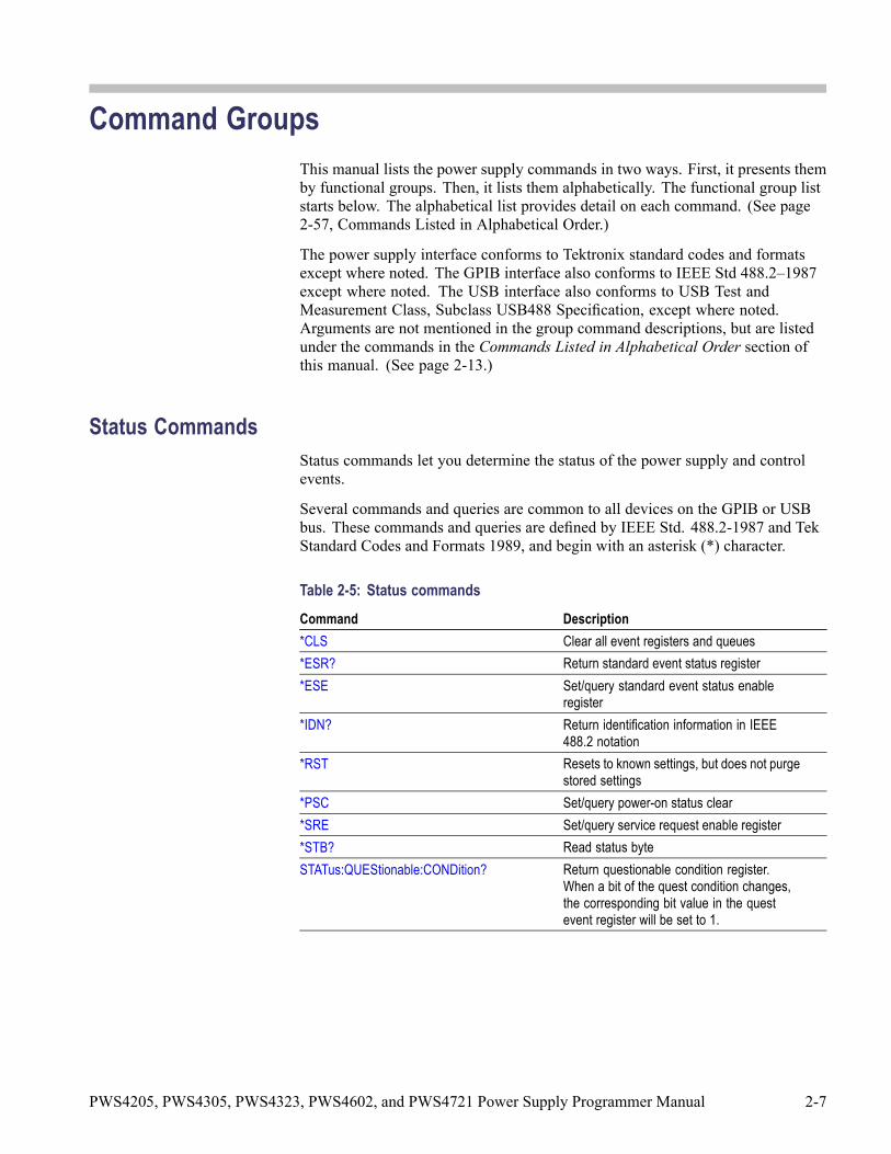
Status CommandsStatus commands let you determine the status of the power supply and controlevents.
Several commands and queries are common to all devices on the GPIB or USBbus. These commands and queries are defined by IEEE Std. 488.2-1987 and TekStandard Codes and Formats 1989, and begin with an asterisk (*) character.
Table 2-5: Status commandsCommand Description*CLS Clear all event registers and queues*ESR? Return standard event status register*ESE Set/query standard event status enable
register*IDN? Return identification information in IEEE
488.2 notation*RST Resets to known settings, but does not purge
stored settings*PSC Set/query power-on status clear*SRE Set/query service request enable register*STB? Read status byteSTATus:QUEStionable:CONDition? Return questionable condition register.
When a bit of the quest condition changes,the corresponding bit value in the questevent register will be set to 1.
PWS4205, PWS4305, PWS4323, PWS4602, and PWS4721 Power Supply Programmer Manual 2-7

Command Groups
Table 2-5: Status commands (cont.)
Command DescriptionSTATus:QUEStionable:ENABle Set/query questionable enable register. This
parameter determines which bit of the questevent register is set to 1. If a QUES conditionchanges, the QUES bit of status byte registerwill be set to 1.
STATus:QUEStionable[:EVENt]? Return questionable event registerSTATus:QUEStionable:PTRansition Edit the rising edge parameter of quest event
registerSTATus:QUEStionable:NTRansition Edit the trailing edge parameter of quest
event registerSTATus:OPERation:CONDition? Return operation condition register. When
a parameter of the operation conditionregister changes, the corresponding bit inthe operation event register will be set to 1.
STATus:OPERation:ENABle Set/query operation enable register. Theparameter determines which bit value ofquest event register is set to 1. If a OPERcondition changes, the OPER bit of thestatus byte register will be set to 1.
STATus:OPERation[:EVENt]? Return operation event register
Save and Recall CommandsSave and recall commands allow you to save the active settings to one of thesettings memories within the power supply, and recall those settings at a later time.
Table 2-6: Save and recall commandsHeader Description*SAV Save instrument setting to setup memory*RCL Recall instrument setting from setup memory
System CommandsTable 2-7: System commandsHeader DescriptionSYSTem:POSetup Set power-on parametersSYSTem:VERSion? Return version informationSYSTem:ERRor? Return error code and error informationSYSTem:KEY Set key operation
2-8 PWS4205, PWS4305, PWS4323, PWS4602, and PWS4721 Power Supply Programmer Manual

Command Groups
Table 2-7: System commands (cont.)
Header DescriptionSYSTem:REMote Set to remote modeSYSTem:RWLock Set to remote mode and lock front-panelSYSTem:LOCal Set to front-panel control modeCONFigure:SOUNd[:STATe] Set key beep sound on or off
Diagnostic CommandsThe power supply includes a self test function that may be used to confirm that itis functioning as expected. A table of error codes that may be returned by the selftest are given in the Messages and Codes section. (See page 3-8.)
Table 2-8: Diagnostic commandsHeader Description*TST? Perform self-test and return result status
Synchronization CommandsTable 2-9: Synchronization commandsHeader Description*OPC Set/query operation complete*WAI Wait to continue
Trigger CommandsTrigger commands are used to determine the timing of list mode sequences.
Table 2-10: Trigger commandsHeader DescriptionTRIGger[:IMMediate] Forces an immediate trigger eventTRIGger:SOURce Set/query the source of trigger signal*TRG Generates a trigger event
PWS4205, PWS4305, PWS4323, PWS4602, and PWS4721 Power Supply Programmer Manual 2-9

Command Groups
Measurement CommandsMeasurement commands are used to query parameters. The MEASure commandsinitiate and execute a complete measurement cycle and are recommended formeasuring voltage and current at the outputs of the power supply. FETChcommands do not initiate a new measurement cycle but rely on measurementsstored in the communication buffers of the power supply. The FETCh commandsare provided for voltage and current measurements to maintain compatibilitywith other instruments. Output power, however, is only available using a FETChcommand.
Table 2-11: Measurement commandsCommand DescriptionMEASure:VOLTage[:DC]? Query the measured output voltageMEASure:CURRent[:DC]? Query the measured output currentFETCh:CURRent[:DC]? Query the measured output currentFETCh[:SCALar]:POWer? Query the measured output powerFETCh:VOLTage[:DC]? Query the measured output voltage
Source CommandsThese commands allow you to set various output parameters. Some of thecommands are used to configure protection functions like OVP and Max Voltage.
Table 2-12: Source commandsCommand Description[SOURce:]CURRent[:LEVel] Set the current value in units of A or mA[SOURce:]OUTPut:TIMer[:STATe] Set the state of the output timer[SOURce:]OUTPut[:STATe] Set power supply output on or off[SOURce:]OUTPut:TIMer:DELay Set the time of output timer[SOURce:]OUTPut:PON[:STATe] Set output on or off at power on[SOURce:]VOLTage:RANGe Set maximum allowable voltage level[SOURce:]VOLTage[:LEVel] Set voltage value[SOURce:]VOLTage:PROTection:STATe Activates overvoltage protection (OVP)[SOURce:]VOLTage:PROTection[:LEVel] Set overvoltage protection (OVP) threshold[SOURce:]OUTPut:PROTection:CLEar Clear a trip condition caused by overvoltage
or over-temperature, or reset a latchedremote-inhibit state
2-10 PWS4205, PWS4305, PWS4323, PWS4602, and PWS4721 Power Supply Programmer Manual
Command Groups
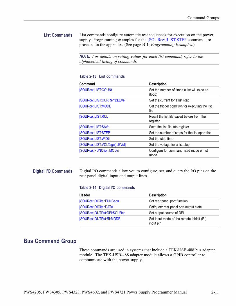
List Commands List commands configure automatic test sequences for execution on the powersupply. Programming examples for the [SOURce:]LIST:STEP command areprovided in the appendix. (See page B-1, Programming Examples.)
NOTE. For details on setting values for each list command, refer to thealphabetical listing of commands.
Table 2-13: List commandsCommand Description[SOURce:]LIST:COUNt Set the number of times a list will execute
(loop)[SOURce:]LIST:CURRent[:LEVel] Set the current for a list step[SOURce:]LIST:MODE Set the trigger condition for executing the list
file[SOURce:]LIST:RCL Recall the list file saved before from the
register[SOURce:]LIST:SAVe Save the list file into register[SOURce:]LIST:STEP Set the number of steps for the list operation[SOURce:]LIST:WIDth Set the step time[SOURce:]LIST:VOLTage[:LEVel] Set the voltage for a list step[SOURce:]FUNCtion:MODE Configure for command fixed mode or list
mode
Digital I/O Commands Digital I/O commands allow you to configure, set, and query the I/O pins on therear panel digital input and output lines.
Table 2-14: Digital I/O commandsHeader Description[SOURce:]DIGital:FUNCtion Set rear panel port function[SOURce:]DIGital:DATA Set/query rear panel port output state[SOURce:]OUTPut:DFI:SOURce Set output source of DFI[SOURce:]OUTPut:RI:MODE Set input mode of the remote inhibit (RI)
input pin
Bus Command GroupThese commands are used in systems that include a TEK-USB-488 bus adaptermodule. The TEK-USB-488 adapter module allows a GPIB controller tocommunicate with the power supply.
PWS4205, PWS4305, PWS4323, PWS4602, and PWS4721 Power Supply Programmer Manual 2-11

Command Groups
Table 2-15: Bus commandsHeader DescriptionGPIBUsb:ADDress? Allows TEK-USB-488 to query the GPIB
Primary Address set for this instrumentGPIBUsb:ID? Query the ID string of the TEK-USB-488 bus
adapter module
2-12 PWS4205, PWS4305, PWS4323, PWS4602, and PWS4721 Power Supply Programmer Manual

Commands Listed in Alphabetical OrderYou can use commands to either set instrument features or query instrumentvalues. You can use some commands to do both, some only to set and some onlyto query. This document marks set-only commands with the words “No QueryForm” included with the command name. It marks query-only commands witha question mark appended to the header, and includes the words “Query Only”in the command name.
This document spells out headers, mnemonics, and arguments with the minimalspelling shown in uppercase. For example, to use the abbreviated form of theMEASure:SCALar:VOLTage:DC? command, type MEAS:SCAL:VOLT:DC?.
*CLS (No Query Form)The *CLS command clears all event registers and queues.
Group Status
Syntax *CLS
Related Commands *ESR?, *STB?
PWS4205, PWS4305, PWS4323, PWS4602, and PWS4721 Power Supply Programmer Manual 2-13
Commands Listed in Alphabetical Order
CONFigure:SOUNd[:STATe]This command turns the key beep sound on or off.
Group System
Syntax CONFigure:SOUNd[:STATe] {0|1|ON|OFF}CONFigure:SOUNd[:STATe]?
Arguments 0 or OFF turns the key beep sound off.
1 or ON turns the key beep sound on.
Returns 0|1
Examples CONF:SOUN:OFF
CONF:SOUN? might return 0, indicating the key beeper is turned off.
*ESESets and queries the bits in the Event Status Enable Register (ESER). The ESERis an eight-bit mask register that determines which bits in the Standard EventStatus Register(SESR) will set the ESB bit in the Status Byte Register (SBR). (Seepage 3-1, Status and Events.)
Group Status
Syntax *ESE <mask>*ESE?
Related Commands *CLS, *ESR?
Arguments <mask>::=<NR1> where:
<NR1> is a value in the range from 0 through 255. The binary bits of the ESERare set according to this value.
The power-on default for ESER is 0 if *PSC is 1. If *PSC is 0, the ESERmaintains its value through a power cycle.
2-14 PWS4205, PWS4305, PWS4323, PWS4602, and PWS4721 Power Supply Programmer Manual

Commands Listed in Alphabetical Order
Examples *ESE 145 sets the ESER to binary 10010001, which enables the PON, EXE,and OPC bits.
*ESE might return the string *ESE 186, showing that the ESER contains thebinary value 10111010.
*ESR? (Query Only)Returns the contents of the Standard Event Status Register (SESR). *ESR? alsoclears the SESR (since reading the SESR clears it). (See page 3-1, Status andEvents.)
Group Status
Syntax *ESR?
Related Commands *CLS, *OPC, *SRE,
Returns <NR1>, which is a decimal representation of the contents of the Standard EventStatus Register (SESR).
Examples *ESR? might return the value 149, showing that the SESR contains binary10010101.
FETCh:CURRent[:DC]? (Query Only)This command returns the last measured output current stored in thecommunications buffer of the power supply. A new measurement is not initiatedby this command.
Group Measurement
Syntax FETCh:CURRent[:DC]?
Related Commands MEASure:CURRent[:DC]?
Returns <NR2>, which gives is the measured output current in amperes.
PWS4205, PWS4305, PWS4323, PWS4602, and PWS4721 Power Supply Programmer Manual 2-15

Commands Listed in Alphabetical Order
Examples FETC:CURR? might return 0.09998, which would be the current measured at theoutput of t he power supply in amperes.
FETCh:VOLTage[:DC]? (Query Only)This command returns the last measured output voltage stored in thecommunications buffer of the power supply. A new measurement is not initiatedby this command.
Group Measurement
Syntax FETCh:VOLTage[:DC]?
Related Commands MEASure:VOLTage[:DC]?
Returns <NR2> is the measured output voltage in volts.
Examples FETC:VOLT? might return 5.0011, which would be the measured voltage acrossthe power supply outputs in volts.
FETCh[:SCALar]:POWer? (Query Only)This command returns the last measured output current stored in thecommunications buffer of the power supply. A new measurement is not initiatedby this command. The power calculation in the instrument is performedapproximately every 100 ms. Insure that the voltage and current are stable longerthan this for good results.
Group Measurement
Syntax FETCh[:SCALar]:POWer?
Returns <NR2> is the measured output power in watts.
Examples FETCh:POW? might return 6.01667, which would be the power measured at theoutput of t he power supply in watts.
2-16 PWS4205, PWS4305, PWS4323, PWS4602, and PWS4721 Power Supply Programmer Manual
Commands Listed in Alphabetical Order
GPIBUsb:ADDress? (Query Only)For use in systems that include a TEK-USB-488 bus adapter module. Returns theGPIB primary address of the instrument. Please refer to To Change GPIB AddressSettings to learn how to set the GPIB address. Valid addresses are integers in therange of 1 to 30. (See page 1-2, To Change GPIB Address Settings.)
Group Bus
Syntax GPIBUsb:ADDress?
Returns <NR1> is the GPIB address of the power supply, as specified on the front-panel ofthe instrument. The range is from 1 to 30.
Examples GPIBU:ADD? might respond with 5, which is the GPIB address of the instrument.
GPIBUsb:ID? (Query Only)For use in systems that include a TEK-USB-488 bus adapter module. Returns theidentification string of a TEK-USB-488 bus adapter module.
Group Bus
Syntax GPIBUsb:ID?
Returns <manufacturer>, <model>, <serial number>, <firmware_version>
Examples GPIBU:ID?
*IDN? (Query Only)Returns the power supply identification code in IEEE 488.2 notation.
Group Status
Syntax *IDN?
PWS4205, PWS4305, PWS4323, PWS4602, and PWS4721 Power Supply Programmer Manual 2-17

Commands Listed in Alphabetical Order
Returns A string that includes <manufacturer>, <model>, <serial number>, and<firmware_version> as defined in the following table.
<manufacturer> <model> <serial number> <firmware_version>tektronix PWS4XXX XXXXXX X. XX-X. XX
Examples *IDN?
might return the following response for a PWS4323:TEKTRONIX , PWS4323 , 000004 , 1.01–1.20
MEASure:CURRent[:DC]? (Query Only)This command initiates and executes a new current measurement, and returns themeasured output current of the power supply.
Group Measurement
Syntax MEASure:CURRent[:DC]?
Related Commands FETCh:VOLTage[:DC]?
Returns <NR2> is the measured output current in amperes.
Examples MEAS:CURR? might return 0.09998, which would be the measured current on theoutput of the power supply in amperes.
MEASure:VOLTage[:DC]? (Query Only)This command initiates and executes a new voltage measurement, and returns themeasured output voltage of the power supply.
Group Measurement
Syntax MEASure:VOLTage[:DC]?
Related Commands FETCh:VOLTage[:DC]?
2-18 PWS4205, PWS4305, PWS4323, PWS4602, and PWS4721 Power Supply Programmer Manual

Commands Listed in Alphabetical Order
Returns <NR2> is the measured output voltage in volts.
Examples MEAS:VOLT? might return 5.0011 which would be the voltage measured acrossthe power supply output in volts.
*OPCThis command configures the instrument to generate an operation completemessage by setting bit 0 of the Standard Event Status Register (SESR) when allpending commands that generate an OPC message are complete.
The query command places the ASCII character "1" into the output queue whenall such OPC commands are complete.
Group Synchronization
Syntax *OPC*OPC?
Examples *OPC? might return 1 to indicate that all pending OPC operations are finished.
*PSCSets and queries the power-on status flag that controls the automatic power-onexecution of SRER and ESER. When *PSC is true, the SRER and ESER are set to0 at power-on. When *PSC is false, the current values in the SRER and ESERare preserved in nonvolatile memory when power is shut off and are restoredat power-on.
Group Source
Syntax *PSC <NR1>*PSC?
Related Commands *RST, *OPC
Arguments <NR1> = 0 sets the power-on status clear flag to false, disables the power-on clear,and allows the power supply to possibly assert SRQ after power on.
<NR1> ≠ 0 sets the power-on status clear flag to true. Sending *PSC 1 thereforeenables the power-on status clear and prevents any SRQ assertion after power-on.
PWS4205, PWS4305, PWS4323, PWS4602, and PWS4721 Power Supply Programmer Manual 2-19

Commands Listed in Alphabetical Order
Returns 0|1
Examples *PSC 0
sets the power-on status clear flag to false.
*PSC?might return 1, indicating that the power-on status clear flag is set to true.
*RCL (No Query Form)Restores the state of the power supply from a copy of its settings stored in thesetup memory. The settings are stored using the *SAV command. If the specifiedsetup memory is deleted, this command causes an error.
Group Save and Recall
Syntax *RCL <NR1>
Related Commands *SAV
Arguments <NR1> is an integer value in the range from 0 to 40 and specifies the locationof setup memory.
Examples *RCL 3
sets the power supply to settings stored in memory location 3.
*RST (No Query Form)This command resets the power supply to default settings, but does not purgeany stored settings.
Sending the *RST command does the following:
Returns the power supply settings to the defaults. (See page C-1, DefaultSetup.)
Clears the pending operation flag and associated operations
2-20 PWS4205, PWS4305, PWS4323, PWS4602, and PWS4721 Power Supply Programmer Manual
Commands Listed in Alphabetical Order
The *RST command does not change the following items:
State of the USB or GPIB interface
Calibration data that affects device specifications
Current GPIB power supply address
Stored settings
Output queue
Service Request Enable Register settings
Standard Event Status Enable Register settings
Power-On Status Clear flag setting
front-panel LOCK state
Group Status
Syntax *RST
*SAV (No Query Form)Saves the state of the power supply into a specified nonvolatile memory location.Any settings that had been stored previously at the location are overwritten. Youcan later use the *RCL command to restore the power supply to this saved state.
Group Status
Syntax *SAV <NR1>
Related Commands *RCL
Arguments <NR1> is an integer value in the range from 1 to 40.
Examples *SAV 2
saves the settings in memory location 2.
[SOURce:]CURRent[:LEVel]This command sets the current value of the power supply in units of A or mA.
PWS4205, PWS4305, PWS4323, PWS4602, and PWS4721 Power Supply Programmer Manual 2-21

Commands Listed in Alphabetical Order
Group Source
Syntax [SOURce:]CURRent[:LEVel] {<current>|MIN|MAX|DEF}[SOURce:]CURRent[:LEVel]?
Arguments <current>::=<NRf><units>
where NRf is a flexible decimal between the minimum current and maximumnameplate current for the power supply. <units>::={mA|A}
MIN sets the current to the minimum level (0 A).
MAX sets the current to the maximum level.
DEF sets the current to the default level (0.1 A).
Returns <NR2> is the current setting in amperes.
Examples CURR 3A
CURR 30mA
CURR MIN
CURR? might return 2.0000, which would be the current setting in amperes.
[SOURce:]DIGital:DATAThis command sets the output state of the rear-panel TTL control output andqueries the state of the rear-panel TTL control input. When the port mode isDIGITAL, this command is enabled.
Group Source
Syntax [SOURce:]DIGital:DATA <NR1>[SOURce:]DIGital:DATA?
Arguments <NR1>::={0|1} sets the binary state of the rear-panel TTL control output tolow or high state, respectively.
Returns <NR1>::={0|1|2|3} is a decimal representation of the state of the rear-panelTTL control output and input.
2-22 PWS4205, PWS4305, PWS4323, PWS4602, and PWS4721 Power Supply Programmer Manual

Commands Listed in Alphabetical Order
Value Input Pin 9 & 10 Output Pin 11 & 120 Low Low1 Low High2 High Low3 High High
Examples DIGITAL:DATA ON
DIGITAL:DATA? might return 3, which would indicate that the TTL controlinput is high and the output is also high.
[SOURce:]DIGital:FUNCtionThis command sets or queries the function of the TTL control lines on the rearpanel of the power supply.
*RST value is TRIGger.
Group Source
Syntax [SOURce:]DIGital:FUNCtion {TRIGger|RIDFi|DIGital}[SOURce:]DIGital:FUNCtion?
Related Commands TRIGger:SOURce, [SOURce:]OUTPut:DFI:SOURce, [SOURce:]DIGital:DATA
Arguments Port mode In Out DecriptionTRIGger Trigger
InN/A Configures the TTL control input as an external
trigger source.RIDFi RI DFI Configures the TTL control input as a remote
inhibit (RI) input. The RI input can be used toturn the power supply output on or off from anexternal signal.Configures the TTL control output as a DiscreteFault Input (DFI). The DFI output provides asignal indicating a
DIGital DI DO It can read and control the output portstate by command. It configures the TTLinput and output for direct control using the[SOURce:]DIGital:DATA command.
PWS4205, PWS4305, PWS4323, PWS4602, and PWS4721 Power Supply Programmer Manual 2-23

Commands Listed in Alphabetical Order
Returns TRIG|RIDF|DIG
Examples DIGITAL:FUNCTION TRIGGER
DIG:FUNC? might return RIDF, which would indicate that the TTL inputand output are configure to function as remote inhibit and discrete fault inputrespectively.
[SOURce:]FUNCtion:MODEThis command configures the power supply to respond to discrete commands orto operate in list mode. Use this command with the FIXed parameter to exit listmode and prepare the instrument to respond to discrete settings changes.
Group Source
Syntax [SOURce:]FUNCtion:MODE {FIXed|LIST}[SOURce:]FUNCtion:MODE?
Arguments FIXed configures the power supply to respond to discrete commands.
LIST configures the power supply to operate in list mode.
Returns FIX|LIST
Examples [SOURCE:]FUNCTION:MODE LIST
[SOURce:]LIST:COUNtThis command configures the number of times the active list will execute beforestopping.
Group Source
Syntax [SOURce:]LIST:COUNt {<NR1>|ONCE|REPeat}[SOURce:]LIST:COUNt?
Related Commands [SOURce:]LIST:MODE, [SOURce:]LIST:STEP
2-24 PWS4205, PWS4305, PWS4323, PWS4602, and PWS4721 Power Supply Programmer Manual

Commands Listed in Alphabetical Order
Arguments <NR1> is an integer between 2 and 65535. It determines the number of times theactive list will execute.ONCe: configures the lists to execute once and stop.REPeat: configures the lists to loop continuously.
Returns <NR1> is the number of times the active list is set to execute.
Examples LIST:COUNT 6 would set the active list to execute 6 times before stopping.
[SOURce:]LIST:CURRent[:LEVel]This command sets the current for a list step in units of A or mA.
Group Source
Syntax [SOURce:]LIST:CURRent[:LEVel] <NR1>,<current>[SOURce:]LIST:CURRent[:LEVel]? <NR1>
Related Commands [SOURce:]LIST:VOLTage[:LEVel], [SOURce:]LIST:WIDth
Arguments <NR1> is an integer in the range from 1 to 80, , which is a step number in theactive list.
<current>::=<NRf>[<units]
where<NRf> is a flexible decimal number used to specify a current setting in the range 0amperes to the nameplate current rating of the power supply.<units>::={A|mA}
Returns <NR2> is a decimal representing the current setting in amperes for the stepspecified in the query.
Examples LIST:CURR 1, 3A
LIST:CURR? 1 might respond with 3.0000, which indicates the current levelsetting for step number 1.
PWS4205, PWS4305, PWS4323, PWS4602, and PWS4721 Power Supply Programmer Manual 2-25
Commands Listed in Alphabetical Order
[SOURce:]LIST:MODEThis command determines the response of the power supply to a trigger in listmode.
Group Source
Syntax [SOURce:]LIST:MODE {CONTinuous|STEP}[SOURce:]LIST:MODE?
Related Commands [SOURce:]LIST:COUNt, [SOURce:]LIST:STEP
Arguments CONTinuous: Sets the power supply to execute the entire list in response toa trigger.
STEP: Sets the power supply to execute one step per trigger.
Returns CONT|STEP
Examples LIST:MODE CONT
LIST:MODE?might respond with STEP to indicate that the active list is configuredto wait for one trigger for each step.
[SOURce:]LIST:RCL (No Query Form)This command recalls a previously saved list from the specified storage locationand makes it the active list for editing or execution.
Group Source: List
Syntax [SOURce:]LIST:RCL <NR1>
Related Commands [SOURce:]LIST:SAVe
Arguments <NR1> is an integer in the range from 1 to 8, representing a list storage location.
Examples LIST:RCL 5 would make the list stored in location 5 the active list for editingor execution.
2-26 PWS4205, PWS4305, PWS4323, PWS4602, and PWS4721 Power Supply Programmer Manual

Commands Listed in Alphabetical Order
[SOURce:]LIST:SAVe (No Query Form)This command saves the active list file to a storage location in non-volatilememory.
Group Source
Syntax [SOURce:]LIST:SAVe <NR1>
Related Commands [SOURce:]LIST:RCL
Arguments <NR1> is an integer in the range from 1 to 8, representing a list storage location.
Examples LIST:SAV 4 saves the active list in list storage location 4.
[SOURce:]LIST:STEPThis command configures the number of steps in the active list. The number ofsteps must be configured before loading the voltage levels, current levels, and/ordurations of the steps.
Group Source: List
Syntax [SOURce:]LIST:STEP {<NR1>|MIN|MAX}[SOURce:]LIST:STEP?
Related Commands [SOURce:]LIST:COUNt, [SOURce:]LIST:MODE
Arguments <NR1> is an integer in the range from 2 to 80, representing the number of steps tobe configured in the list.
Returns <NR1> is the number of steps configured in the active list.
Examples Examples are provided at the end of this manual. (See page B-1, ProgrammingExamples.)
PWS4205, PWS4305, PWS4323, PWS4602, and PWS4721 Power Supply Programmer Manual 2-27

Commands Listed in Alphabetical Order
[SOURce:]LIST:VOLTage[:LEVel]This command sets the voltage level of a specified step in a list in units of V or mV.
Group Source: List
Syntax [SOURce:]LIST:VOLTage[:LEVel] <NR1>,<voltage>
Arguments <NR1> is an integer in the range from 1 to 80, which is a step number in theactive list.
<voltage>::=<NRf><units>
where<NRf> is a flexible decimal that sets the voltage level fro the step.<units>::={V|mV}
Returns <NR2>
Examples LIST:VOLT 1, 3V
LIST:VOLT? 1 might return 3.0000, which would be the voltage level for stepnumber 1.
[SOURce:]LIST:WIDthThis command sets the duration of a specified step in a list.
Group Source
Syntax [SOURce:]LIST:WIDth <NR1>,{<duration>|MIN|MAX}[SOURce:]LIST:WIDth? <NR1>
Related Commands [SOURce:]LIST:VOLTage[:LEVel], [SOURce:]LIST:CURRent[:LEVel]
Arguments <NR1> is an integer in the range from 1 to 80, which is a step number in the activelist. <duration>::=<NRf><units>where<NRf> is the time duration of the step<units>::={s|ms}
2-28 PWS4205, PWS4305, PWS4323, PWS4602, and PWS4721 Power Supply Programmer Manual

Commands Listed in Alphabetical Order
Returns <NR2>
Examples LIST:WIDTH 12, 100ms
LIST:WIDTH? 12 might return 0.1, which would be the duration of step 12.
[SOURce:]OUTPut:DFI:SOURceThis command associates the DFI TTL output on the rear panel with a specified bitin the status byte register (SBR). Once the bit is associated with the DFI signal, theDFI signal will reflect the state of the specified bit. The port needs to be in the DFIor RI mode before using this command. Use the [SOURce:]DIGital:FUNCtioncommand to set the port mode.
*RST value is OFF.
Group Source: Digital I/O
Syntax [SOURce:]OUTPut:DFI:SOURce {OFF|QUES|OPER|ESB|RQS}[SOURce:]OUTPut:DFI:SOURce?
Related Commands [SOURce:]DIGital:FUNCtion
Arguments OFF: the output level of the DFI output pin remains high.
QUES: the output level of the DFI output pin reflects the complement of the stateof the QUES bit. For example, when the QUES bit is 1, the DFI output pin is low.
OPER: the output level of the DFI output pin reflects the state of the OPER bit.
ESB: the output level of the DFI output pin reflects the state of the ESB bit.
RQS: the output level of the DFI output pin reflects the state of the RQS bit.
Returns OFF|QUES|OPER|ESB|RQS
Examples OUTput:DFI:SOURCE QUES sets the DFI signal to respond to the state of theQUES bit in the status byte register (SBR).
[SOURce:]OUTPut:PON[:STATe]This command configures the power supply to power up with its output turnedoff, or to return the output to the state it was in when it powered down.
PWS4205, PWS4305, PWS4323, PWS4602, and PWS4721 Power Supply Programmer Manual 2-29

Commands Listed in Alphabetical Order
Group Source
Syntax [SOURce:]OUTPut:PON[:STATe] {RST|RCL0}[SOURce:]OUTPut:PON[:STATe]?
Arguments RST sets the power supply to power-up with output off.
RCL0 sets the power supply to power-up with the output in the last state beforepower was removed.
Returns RST|RCL0
Examples OUTPUT:PON RST
OUTPUT:PON? might return RCL0, which would indicate that the instrument willreturn to the present output state if the power is cycled.
[SOURce:]OUTPut:PROTection:CLEar (No Query Form)This command clears a trip condition caused by over voltage (OV), overtemperature (OT), or remote inhibit (RI).
Group Source
Syntax [SOURce:]OUTPut:PROTection:CLEar
Related Commands [SOURce:]VOLTage:PROTection[:LEVel], [SOURce:]VOLTage:PROTection:STATe
Examples OUTP:PROT:CLE
[SOURce:]OUTPut:RI:MODEThis command sets the input mode of the RI (remote inhibit) input pin. In orderfor this command to be effective, the rear panel TTL input and output must beconfigured in RI/DFI mode using the [SOURce:]DIGital:FUNCtion command.
Group Source
2-30 PWS4205, PWS4305, PWS4323, PWS4602, and PWS4721 Power Supply Programmer Manual

Commands Listed in Alphabetical Order
Syntax [SOURce:]OUTPut:RI:MODE {OFF|LATChing|LIVE}[SOURce:]OUTPut:RI:MODE?
Related Commands [SOURce:]DIGital:FUNCtion
Arguments OFF: The level of the RI input pin does not affect the output state of the powersupply.
LATChing: When the level of the RI input pin changes from high to low, theoutput of power supply turns off.
LIVE: The output state of power supply changes according to the level of the RIinput pin. While the level is TTL high, the output will be on. While the level isTTL low, the output of the power supply will be off.
Returns OFF|LATC|LIVE
Examples OUTP:RI:MODE LATC
OUTP:RI:MODE? might return OFF, which would indicate that remote inhibit isnot controlling the output of the instrument.
[SOURce:]OUTPut[:STATe]This command turns the power supply output channel on or off.
Group Source
Syntax [SOURce:]OUTPut[:STATe] {0|1|ON|OFF}[SOURce:]OUTPut[:STATe]?
Related Commands [SOURce:]OUTPut:TIMer[:STATe]
Arguments 0 or OFF turns the power supply output off.
1 or ON turns the power supply output on.
Returns 1|0
PWS4205, PWS4305, PWS4323, PWS4602, and PWS4721 Power Supply Programmer Manual 2-31

Commands Listed in Alphabetical Order
Examples OUTPUT ON
OUTPUT? might return 0, which would indicate that the output is off.
[SOURce:]OUTPut:TIMer:DELayThis command sets the time duration of the output timer. When the timer isactivated and a duration is set, the output of the power supply will turn offautomatically if left on longer than the specified duration. In order to ensureproper operation of the output timer, the timer must be activated using the[SOURce:]OUTPut:TIMer[:STATe] command before turning the output on.
Group Source
Syntax [SOURce:]OUTPut:TIMer:DELay {<duration>|MIN|MAX|DEF}[SOURce:]OUTPut:TIMer:DELay?
Related Commands [SOURce:]OUTPut:TIMer[:STATe], [SOURce:]OUTPut[:STATe]
Arguments <duration> ::= <NRf><units>
where<NRf> is a flexible decimal specifying time in the range 0.01s (or 10ms) to60000s.<units>::={S|ms}
MIN: The minimum time of the output timer (0.01 s).
MAX: The maximum time of the output timer (60,000 s).
DEF: The default time of the output timer (60 s).
Returns <NR2> is the timer duration in seconds.
Examples OUTP:TIM:DEL MIN
OUTP:TIM:DEL? might return 60.2, which would represent the maximum time,in seconds, that the output of the instrument could be turned on if the timeris active.
[SOURce:]OUTPut:TIMer[:STATe]This command turns the output timer function on and off. When the timer isactivated and a duration is set, the output of the power supply will turn off
2-32 PWS4205, PWS4305, PWS4323, PWS4602, and PWS4721 Power Supply Programmer Manual
Commands Listed in Alphabetical Order
automatically if left on longer than the specified duration. In order to ensureproper operation of the output timer, the timer must be activated using the[SOURce:]OUTPut:TIMer[:STATe] command before turning the output on.
Group Source
Syntax [SOURce:]OUTPut:TIMer[:STATe] {0|1|ON|OFF}[SOURce:]OUTPut:TIMer[:STATe]?
Related Commands [SOURce:]OUTPut:PROTection:CLEar, [SOURce:]OUTPut:TIMer:DELay,[SOURce:]OUTPut[:STATe]
Arguments 0 or OFF turns the output timer off.
1 or ON turns the output timer on.
Returns 0|1
Examples To start timer, first send OUTPUT:TIMER:STATE ON, then send OUTPUT:STATEON.
To end timer (turn timer off), send OUTPUT:TIMER:STATE OFF.
[SOURce:]VOLTage[:LEVel]This command sets the voltage value of the power supply.
Group Source
Syntax [SOURce:]VOLTage[:LEVel] {<NRf>|MIN|MAX|DEF}[SOURce:]VOLTage[:LEVel]?
Related Commands [SOURce:]CURRent[:LEVel]
Arguments <voltage>
where<voltage>::=<NRf><units>
<NRf> is a flexible decimal specifying the voltage setting, ranging from 0 to themaximum nameplate voltage of the power supply.<units>::={V|mV|kV}
PWS4205, PWS4305, PWS4323, PWS4602, and PWS4721 Power Supply Programmer Manual 2-33

Commands Listed in Alphabetical Order
MIN sets the voltage to the minimum level (0 V).
MAX sets the voltage to the maximum level (note that the maximum level may besomewhat higher than the nameplate).
DEF is the default level (1 V).
Returns NR2 is the voltage setting in volts.
Examples VOLTAGE:MIN
VOLTAGE? might return 1.05, which would be the voltage setting in volts.
[SOURce:]VOLTage:PROTection[:LEVel]This command sets the over voltage protection (OVP) threshold level.
Group Source
Syntax [SOURce:]VOLTage:PROTection[:LEVel] {<voltage>|MIN|MAX|DEF}[SOURce:]VOLTage:PROTection[:LEVel]?
Related Commands [SOURce:]VOLTage:PROTection:STATe, [SOURce:]VOLTage:RANGe
Arguments <voltage>::=<NRf><units>
where<NRf> is a flexible decimal that specifies the OVP threshold, ranging from 0 tothe maximum OVP level<units> ::={V|mV}
MIN: sets the minimum OVP level (1 V).
MAX: sets the maximum OVP level, which is approximately 10% higher than themaximum output voltage rating of the power supply.
DEF: sets the OVP level to the default level, which is equal to MAX.
Returns <NR2> is the OVP threshold in volts.
MIN: set to minimum OVP level.
MAX: set to maximum OVP level.
2-34 PWS4205, PWS4305, PWS4323, PWS4602, and PWS4721 Power Supply Programmer Manual

Commands Listed in Alphabetical Order
Examples VOLT:PROT 30V
VOLT:PROT? might return 30, which would be the OVP threshold in volts.
[SOURce:]VOLTage:PROTection:STATeThis command activates, deactivates, or checks the status of overvoltageprotection (OVP).
Group Source
Syntax [SOURce:]VOLTage:PROTection:STATe {0|1|OFF|ON}[SOURce:]VOLTage:PROTection:STATe?
Related Commands [SOURce:]VOLTage:PROTection[:LEVel], [SOURce:]VOLTage:RANGe
Arguments 0 or OFF sets the over voltage protection to off.
1 or ON sets the over voltage protection to on.
Returns 0|1 means the over voltage protection is off.
Examples VOLT:PROT:STAT 1
VOLT:PROT:STAT? might return 1, which would indicate that overvoltageprotection is active.
[SOURce:]VOLTage:RANGeThis command limits the maximum voltage that can be programmed on the powersupply. This command corresponds to the front-panel Max Voltage setting thatcan be found under the Protection submenu. This function is different from OVP,since it cannot turn the output off.
Group Source
Syntax [SOURce:]VOLTage:RANGe {<voltage>|MIN|MAX|DEF}[SOURce:]VOLTage:RANGe?
PWS4205, PWS4305, PWS4323, PWS4602, and PWS4721 Power Supply Programmer Manual 2-35
Commands Listed in Alphabetical Order
Related Commands [SOURce:]VOLTage:PROTection[:LEVel], [SOURce:]VOLTage:PROTection:STATe
Arguments <voltage>::=<NRf><units>
where<NRf> is a flexible decimal that sets the maximum output voltage, ranging from 0to the maximum nameplate voltage<units>::={V|mV|kV}
MIN: sets the voltage limit to the minimum value (0 V).
MAX: sets the voltage limit to the maximum value which is slightly higher than themaximum nameplate voltage.
DEF: sets the voltage limit to the default value, which equals MAX.
Returns <NR2> is the voltage limit in volts.
Examples VOLT:RANG 3.2V
VOLT:RANG? might return 3.2, which would be the maximum programmablevoltage in volts.
*SRE(Service Request Enable) sets and queries the bits in the Service Request EnableRegister (SRER). Refer to the Status and Events chapter for more information.
Group Status
Syntax *SRE <NR1>*SRE?
Related Commands *CLS, *ESR?, *PSC
Arguments <NR1> is an integer value in the range from 0 to 255. The binary bits of the SRERare set according to this value. Using an out-of-range value causes an executionerror. The power-on default for SRER is 0 if *PSC is 1. If *PSC is 0, the SRERmaintains its value through a power cycle.
2-36 PWS4205, PWS4305, PWS4323, PWS4602, and PWS4721 Power Supply Programmer Manual

Commands Listed in Alphabetical Order
Examples *SRE 48 sets the bits in the SRER to 00110000 binary.
*SRE? might return a value of 32, showing that the bits in the SRER have thebinary value 00100000.
STATus:OPERation:CONDition? (Query Only)This command returns the contents of the operation condition register (OCR).Details on the OCR are available in this manual. (See page 3-1, Status and Events.)
Group Status
Syntax STATus:OPERation:CONDition?
Related Commands STATus:OPERation:ENABle, STATus:OPERation[:EVENt]?
Returns <NR1> is a decimal integer representation of the contents of the OperationCondition Register (OCR), ranging from 0 to 255.
Examples STATUS:OPERATION:CONDITION? might return 4, which would indicate thatthe power supply is in constant voltage mode.
STATus:OPERation:ENABleThis command sets and queries the contents of the operation enable register(OENR). The OENR is an eight-bit mask register that determines which bits inthe Operation Event Register (OEVR) will affect the state of the OPER bit in theStatus Byte Register (SBR). Details about the status registers are available in thismanual. (See page 3-1, Status and Events.)
Group Status
Syntax STATus:OPERation:ENABle <NR1>STATus:OPERation:ENABle?
Related Commands STATus:OPERation:CONDition?, STATus:OPERation[:EVENt]?
Arguments <mask>::=<NR1>
where
PWS4205, PWS4305, PWS4323, PWS4602, and PWS4721 Power Supply Programmer Manual 2-37

Commands Listed in Alphabetical Order
<NR1> is a decimal integer ranging from 0 through 255. The binary bits of theOENR are set according to this value.
Returns <mask>
Examples STATUS:OPERATION:ENABLE 8
STATUS:OPERATION:ENABLE? might return 8, which would indicate that onlythe Constant Current bit of the Operation Event Register would affect the OPERbit of the Status Byte Register.
STATus:OPERation[:EVENt]? (Query Only)This command returns the contents of the operation event register (OEVR). Afterexecuting this command the operation event register is reset. Details about statusregisters are available in this manual. (See page 3-1, Status and Events.)
Group Status
Syntax STATus:OPERation[:EVENt]?
Related Commands STATus:OPERation:CONDition?, STATus:OPERation:ENABle
Returns <NR1> is a decimal integer representation of the contents of the Operation EventRegister (OEVR), ranging from 0 to 255.
Examples STATUS:OPERATION:EVENT? might return 10, which indicates that the powersupply is waiting for trigger and is in a constant current mode.
STATus:QUEStionable:CONDition? (Query Only)This command returns the contents of the questionable condition register (QCR).Details about the QCR are available in this manual. (See page 3-1, Status andEvents.)
Group Status
Syntax STATus:QUEStionable:CONDition?
2-38 PWS4205, PWS4305, PWS4323, PWS4602, and PWS4721 Power Supply Programmer Manual
Commands Listed in Alphabetical Order
Related Commands STATus:QUEStionable:ENABle, STATus:QUEStionable[:EVENt]?
Returns <NR1> is a decimal integer representation of the contents of the QuestionableCondition Register (OCR), ranging from 0 to 255.
Examples STATUS:QUESTIONABLE:CONDITION? might return 1, which would indicate anover voltage condition.
STATus:QUEStionable:ENABleThis command sets and queries the contents of the questionable enable register(QENR). The QENR is an eight-bit mask register that determines which bits inthe Questionable Event Register (QEVR) will affect the state of the QUES bit inthe Status Byte Register (SBR).
Group Status
Syntax STATus:QUEStionable:ENABle <mask>STATus:QUEStionable:ENABle?
Related Commands STATus:QUEStionable[:EVENt]?, STATus:QUEStionable:CONDition?,STATus:QUEStionable:PTRansition, STATus:QUEStionable:NTRansition, *PSC
Arguments <mask>::=<NR1>
where<NR1> is a decimal integer ranging from 0 through 255. The binary bits of theQENR are set according to this value.
Returns <mask>
Examples STATUS:QUESTIONABLE:ENABLE 8
STATUS:QUESTIONABLE:ENABLE? might return 8, which would indicate thatonly a transition of the Remote Inhibit bit of the QCR would affect the QUESbit of the Status Byte Register.
PWS4205, PWS4305, PWS4323, PWS4602, and PWS4721 Power Supply Programmer Manual 2-39
Commands Listed in Alphabetical Order
STATus:QUEStionable[:EVENt]? (Query Only)This command returns the contents of the questionable event register (QEVR).After executing this command, the quest event register is reset. Details about theQEVR are available in this manual. (See page 3-1, Status and Events.)
Group Status
Syntax STATus:QUEStionable[:EVENt]?
Related Commands STATus:QUEStionable:ENABle, STATus:QUEStionable:CONDition?,STATus:QUEStionable:PTRansition, STATus:QUEStionable:NTRansition
Returns <NR1> is a decimal integer representation of the contents of the QuestionableEvent Register (QEVR), ranging from 0 to 255.
Examples STATUS:QUESTIONABLE:EVENT? might return 1, which would indicate anovervoltage condition.
STATus:QUEStionable:NTRansitionThis command sets the negative transition filter of the questionable event register.The filter contents cause the corresponding bit in the questionable event registerto become 1 when the bit value of the questionable condition register transitionsfrom 1 to 0.
Group Status
Syntax STATus:QUEStionable:NTRansition <mask>STATus:QUEStionable:NTRansition?
Related Commands STATus:QUEStionable:ENABle, STATus:QUEStionable[:EVENt]?,STATus:QUEStionable:CONDition?, STATus:QUEStionable:PTRansition
Arguments <mask>::=<NR1>
where<NR1> is a number ranging from 0 through 255. The binary bits of theQuestionable NTR register are set according to this value.
2-40 PWS4205, PWS4305, PWS4323, PWS4602, and PWS4721 Power Supply Programmer Manual

Commands Listed in Alphabetical Order
Returns <mask>
Examples STATUS:QUESTIONABLE:NTRANSITION 8
STATUS:QUESTIONABLE:NTRANSITION? might return 8, which would indicatethat a negative transition on the Remote Inhibit bit of the QCR would be registeredas an event.
STATus:QUEStionable:PTRansitionThis command sets the positive transition filter of the questionable event register.The filter contents cause the corresponding bit in the questionable event registerto become 1 when the bit value of the questionable condition register transitionsfrom 0 to 1.
Group Status
Syntax STATus:QUEStionable:PTRansition <mask>STATus:QUEStionable:PTRansition?
Related Commands STATus:QUEStionable:ENABle, STATus:QUEStionable[:EVENt]?,STATus:QUEStionable:CONDition?, STATus:QUEStionable:NTRansition
Arguments <mask>::=<NR1>
where<NR1> is a number ranging from 0 through 255. The binary bits of theQuestionable PTR register are set according to this value.
Returns <mask>
Examples STATUS:QUESTIONABLE:PTRANSITION 8
STATUS:QUESTIONABLE:PTRANSITION? might return 8 which would indicatethat a positive transition on the Remote Inhibit bit of the QCR would be registeredas an event.
*STB? (Query Only)The byte query returns the contents of the Status Byte Register (SBR) using theMaster Summary Status (MSS) bit. Refer to the Status and Events chapter formore information. (See page 3-3.)
PWS4205, PWS4305, PWS4323, PWS4602, and PWS4721 Power Supply Programmer Manual 2-41

Commands Listed in Alphabetical Order
Group Status
Syntax *STB?
Related Commands *ESE, *CLS, *ESR?
Returns <NR1>
Examples *STB? 96
shows that the SBR contains the binary value 01100000.
SYSTem:ERRor? (Query Only)This command queries the error code and error information of the power supplyand returns both values. (See Table 3-6 on page 3-9.)
Group System
Syntax SYSTem:ERRor?
Returns <NR1>,<error_text>
<error_text> ::= <string>
where <string> is a description of the error.
Examples SYSTEM:ERROR? might return 110, which means No Input Command to parse.
SYSTem:KEYThis command can produce the same effect as pressing one of the front-panelbuttons. The instrument must be in local mode in order for this command tosimulate a front-panel button press.
Group System
Syntax SYSTem:KEY <NR1>SYSTem:KEY?
2-42 PWS4205, PWS4305, PWS4323, PWS4602, and PWS4721 Power Supply Programmer Manual

Commands Listed in Alphabetical Order
Arguments <NR1> is an integer key code (see the following table).
Returns <NR1>
Front-panel button <NR1> key codeKEY_VSET 1KEY_ISET 2KEY_SAVE 3KEY_RECALL 4KEY_LEFT 5KEY_RIGHT 6KEY_UP 7KEY_DOWN 8KEY_0 9KEY_1 10KEY_2 11KEY_3 12KEY_4 13KEY_5 14KEY_6 15KEY_7 16KEY_8 17KEY_9 18KEY_DECIMAL 19KEY_ESC 20KEY_ENTER 21KEY_ON 22KEY_SHIFT 64
Examples SYSTEM:KEY 64 would simulate a press of the Shift key.
SYSTem:LOCal (No Query Form)This command sets the power supply for control from the front-panel.
Group System
Syntax SYSTem:LOCal
PWS4205, PWS4305, PWS4323, PWS4602, and PWS4721 Power Supply Programmer Manual 2-43

Commands Listed in Alphabetical Order
Related Commands SYSTem:REMote, SYSTem:RWLock
Examples SYS:LOC
SYSTem:POSetupThis command determines how the power supply initializes when its power switchis turned on. This command configures the instrument to power up with defaultsettings, or power up with the settings that were in effect when the instrumentwas turned off.
Group System
Syntax SYSTem:POSetup {RST|RCL0}SYSTem:POSetup?
Arguments RST: initializes the power supply to default settings after a power cycle.
RCL0: saves the most recent settings and restores these after a power cycle.
Returns RST: default settings are applied after a power cycle.
RCL0: most recent settings are saved and restored after a power cycle.
Examples SYST:POS RST
SYSTEM:POSETUP? might respond with RST, which would indicate that thepower supply is configured to restore the power supply to default settings whenit powers up.
SYSTem:REMote (No Query Form)This command sets the power supply to remote control mode.
Group System
Syntax SYSTem:REMote
Related Commands SYSTem:LOCal, SYSTem:RWLock
2-44 PWS4205, PWS4305, PWS4323, PWS4602, and PWS4721 Power Supply Programmer Manual

Commands Listed in Alphabetical Order
Arguments None.
Examples SYSTEM:REMOTE
SYSTem:RWLock (No Query Form)If the power supply is in remote mode, this command locks out the front panelLOCAL button. This command has no effect if the instrument is in local mode.
Group System
Syntax SYSTem:RWLock
Related Commands SYSTem:REMote, SYSTem:LOCal
Arguments None.
Examples SYSTEM:RWLOCK
SYSTem:VERSion? (Query Only)This command returns SCPI version of the instrument.
Group System
Syntax SYSTem:VERSion?
Returns <NR2> is the software version of the power supply.
Examples SYSTEM:VERSION? might return 1991.0, which is the SCPI version number.
*TRG (No Query Form)This command generates a trigger event.
PWS4205, PWS4305, PWS4323, PWS4602, and PWS4721 Power Supply Programmer Manual 2-45

Commands Listed in Alphabetical Order
Group Trigger
Syntax *TRG
Related Commands TRIGger[:IMMediate]
Examples *TRG
TRIGger[:IMMediate] (No Query Form)This command forces an immediate trigger event.
Group Trigger
Syntax TRIGger[:IMMediate]
Related Commands *TRG
Arguments None.
Examples TRIGGER
TRIGger:SOURceThis command sets the source of trigger events.
Group Trigger
Syntax TRIGger:SOURce {MANual|IMMediate|EXTernal|BUS}TRIGger:SOURce?
Related Commands [SOURce:]DIGital:FUNCtion, *TRG, TRIGger[:IMMediate]
Arguments MANual: When this value is sent, the power supply will wait for a trigger from thefront-panel. Press Shift + 3 (Trigger) to trigger the power supply.
2-46 PWS4205, PWS4305, PWS4323, PWS4602, and PWS4721 Power Supply Programmer Manual

Commands Listed in Alphabetical Order
IMMediate: When this value is sent, the power supply will wait for aTRIgger:IMMediate bus command.
EXTernal: When this value is sent, the power supply can be triggered with aTTL pulse applied to pin 1 of the terminal connector in the rear. The pulse widthshould be at least 5 ms.
BUS: When this value is sent, the power supply can be triggered by sending a*TRG or TRIgger:IMMediate command to the power supply.
Examples TRIGGER:SOURCE BUS
*TST? (Query Only)Initiates a self-test and reports any errors.
Group Diagnostic
Syntax *TST?
Returns <NR1>
where<NR1>= 0 indicates that the self-test completed with no errors.<NR1> not equal to 0 indicates that the self test detected an error.
Self test code descriptions are available. (See Table 3-10 on page 3-10.)
*WAI (No Query Form)This command prevents the instrument from executing further commands orqueries until all pending commands are complete.
Group Synchronization
Syntax *WAI
Examples *WAI
PWS4205, PWS4305, PWS4323, PWS4602, and PWS4721 Power Supply Programmer Manual 2-47

Commands Listed in Alphabetical Order
2-48 PWS4205, PWS4305, PWS4323, PWS4602, and PWS4721 Power Supply Programmer Manual

Status and Events


Status and EventsThis section provides details about the status information and events the powersupply reports.
Status Reporting StructureA diagram is provided showing an outline of the power supply error and eventreporting function. (See Figure 3-1.)
The error and event reporting system consists of the following three blocks:
Standard/Event Status
Operation Status
Questionable Status
The operations processed in these blocks are summarized in status bytes, whichprovide the error and event data.
PWS4205, PWS4305, PWS4323, PWS4602, and PWS4721 Power Supply Programmer Manual 3-1

Status and Events
Figure 3-1: Error and event handling process
3-2 PWS4205, PWS4305, PWS4323, PWS4602, and PWS4721 Power Supply Programmer Manual

Status and Events
RegistersThe registers in the event reporting system fall into two functional groups:
Status Registers contain information about the status of the power supply.They include the Standard Event Status Register (SESR).
Enable Registers determine whether selected types of events are reported tothe Status Registers and the Event Queue. They include the Event StatusEnable Register (ESER), the Service Request Enable Register (SRER), theOperation Enable Register (OENR), and the Questionable Enable Register(QENR).
Status Registers There are six types of status registers:
Status Byte Register (SBR). (See page 3-3.)
Standard Event Status Register (SESR). (See page 3-4.)
Operation Condition Register (OCR). (See page 3-5.)
Operation Event Register (OEVR). (See page 3-5.)
Questionable Condition Register (QCR). (See page 3-5.)
Questionable Event Register (QEVR). (See page 3-6.)
NOTE. The Questionable Event Register may be filtered by a positive transitionfilter (QPTR) and a negative transition filter (QNTR). (See page 3-6.)
The Status Byte Register (SBR). The SBR is made up of 8 bits. Bits 4, 5 and 6 aredefined in accordance with IEEE Std 488.2-1992. These bits are used to monitorthe output queue, SESR, and service requests, respectively. (See Figure 3-2.)
Figure 3-2: The Status Byte Register (SBR)
Table 3-1: SBR bit functionsBit Function7 (MSB) OSB Operation Status Bit. Indicates that an operation
event has occurred.6 RQS Request Service. Obtained from a serial poll. Shows
that the power supply requests service from the GPIBcontroller.
PWS4205, PWS4305, PWS4323, PWS4602, and PWS4721 Power Supply Programmer Manual 3-3

Status and Events
Table 3-1: SBR bit functions (cont.)
Bit Function6 MSS Master Status Summary. Obtained from *STB?
query. Summarizes the OSB, ESB, MAV, QSB, and EQSbits in the SBR.
5 ESB Event Status Bit. Shows that status is enabled andpresent in the SESR.
4 MAV Message Available. Shows that output is availablein the Output Queue.
3 QSB Questionable Status Bit. Indicates that aquestionable event has occurred.
2 EQS Shows that information is available in the Error/EventQueue.
1 ———— Not used.0 ———— Not used.
The Standard Event Status Register (SESR). The SESR records six types of eventsthat can occur within the power supply as shown in the following figure. (SeeFigure 3-3.)
Figure 3-3: The Standard Event Status Register (SESR)
Table 3-2: SESR bit functionsBit Function7 (MSB) PON Power On. Shows that the power supply was powered
on.6 ———— User Request. This bit is not used.5 CME Command Error. Shows that an error occurred while
the power supply was parsing a command or query.4 EXE Execution Error. Shows that an error occurred while
the power supply was executing a command or query.3 DDE Device Error. Shows that a device dependent error
occurred.2 QYE Query Error. Either an attempt was made to read the
Output Queue when no data was present or pending, or thatdata in the Output Queue was lost.
1 ———— Request Control. This bit is not used.0 (LSB) OPC Operation Complete. Shows that the operation
is complete. This bit is set when all pending operationscomplete following an *OPC command.
3-4 PWS4205, PWS4305, PWS4323, PWS4602, and PWS4721 Power Supply Programmer Manual

Status and Events
The Operation Condition Register (OCR). The Operation Condition Register ismade up of eight bits, which note the occurrence of events as shown here.
Figure 3-4: The Operation Condition Register (OCR)
Table 3-3: OCR bit functionsBit Function7 (MSB) ———— This bit is not used.6 ———— This bit is not used.5 RUN Running List. Indicates that the power supply is
executing a list.4 TBF Trace Buffer Full. This bit is used internally, by
the instrument.3 CC Constant Current. Indicates that the power supply is
in constant current mode and is regulating its output current.2 CV Constant Voltage. Indicates that the power supply is
in constant voltage mode and is regulating its output voltage.1 WTG Waiting for Trigger. Indicates that the power
supply is waiting for a trigger.0 (LSB) CAL Calibrating. Indicates that the power supply is
calculating a new calibration parameter.
The Operation Event Register (OEVR). The Operation Event Register has the samecontent as the Operation Condition Register.
The Questionable Condition Register (QCR). The Questionable Condition Registeris made up of eight bits which note the occurrence of five types of events asshown here.
Figure 3-5: The Questionable Condition Register (QCR)
Table 3-4: QCR bit functionsBit Function7 (MSB) ———— This bit is not used.6 ———— This bit is not used.5 ———— This bit is not used.4 PS Protection Shutdown.
3 RI Remote Inhibit. This bit indicates the state of theRemote Inhibit input.
PWS4205, PWS4305, PWS4323, PWS4602, and PWS4721 Power Supply Programmer Manual 3-5

Status and Events
Table 3-4: QCR bit functions (cont.)
Bit Function2 UNR Unregulated. Indicates that the power supply has gone
out of regulation.1 OT Over Temperature. Indicates that the power supply
has experienced an over temperature condition and theoutput has been shut down.
0 (LSB) OV Over Voltage. Indicates that the overvoltage protectionthreshold has been exceeded and the output has shut down.
The Questionable Positive Transition Register (QPTR) and Questionable NegativeTransition Register (QNTR). The QEVR can be configured to respond to specifictransitions in the QCR. The transitions and the polarity of these transitions arespecified in the QPTR and QNTR. These registers act as filters between the QCRand the QEVR. If a bit is set to 1 in the QNTR, the corresponding bit in the QEVRwill be set to 1 whenever the same bit in the QCR makes a negative transition,from 1 to 0. If a bit is set to 1 in the QPTR, the corresponding bit in the QEVR willbe set to 1 when the same bit in the QCR makes a positive transition, from 0 to 1.
The Questionable Event Register (QEVR). The Questionable Event Register ismade up of eight bits, which have the same significance as the QCR, but havebeen filtered by the QPTR and QNTR.
Enable Registers There are four types of enable registers:
Event Status Enable Register (ESER), (See page 3-7.)
Service Request Enable Register (SRER), (See page 3-7.)
Operation Enable Register (OENR), (See page 3-7.)
Questionable Enable Register (QENR), (See page 3-7.)
ESER, SRER, OENR, and QENR allow you to select which events are reported tothe Status Byte Register (SBR).
Each bit in an Enable Register corresponds to a bit in an Event Register. In orderfor an event to be reported to a bit in the Status Byte Register, the correspondingbit in the Enable Register must be set to one. If the bit in the Enable Register is setto zero, the event will not affect the status bit.
Various commands set the bits in the Enable Registers. The Enable Registers andthe commands used to set them are described below.
3-6 PWS4205, PWS4305, PWS4323, PWS4602, and PWS4721 Power Supply Programmer Manual

Status and Events
The Event Status Enable Register (ESER). This register controls which types ofevents are summarized by the Event Status Bit (ESB) in the SBR. Use the *ESEcommand to set the bits in the ESER. Use the *ESE? query to read it.
Figure 3-6: The Event Status Enable Register (ESER)
The Service Request Enable Register (SRER). This register controls which bitsin the SBR generate a Service Request and are summarized by the Master StatusSummary (MSS) bit.
Use the *SRE command to set the SRER. Use the *SRE? query to read theregister. The RQS bit remains set to one until either the Status Byte Register isread with a Serial Poll or the MSS bit changes back to a zero.
Figure 3-7: The Service Request Enable Register (SRER)
The Operation Enable Register (OENR). The OENR consists of bits defined exactlythe same as bits 0 through 7 in the OEVR. You can use this register to controlwhether or not the Operation Status Bit (OSB) in the SBR is set when an eventoccurs and the corresponding OEVR bit is set.
Use the STATus:OPERation:ENABle command to set the bits in the OENR.
Use the STATus:OPERation:ENABle? query to read the contents of the OENR.
Figure 3-8: The Operation Enable Register (OENR)
The Questionable Enable Register (QENR). The QENR consists of bits definedexactly the same as bits 0 through 7 in the QEVR register. You can use thisregister to control whether the QSB in the SBR is set when an event occurs andthe corresponding QEVR bit is set.
Use the STATus:QUEStionable:ENABle command to set the bits in the QENR
Use the STATus:QUEStionable:ENABle? query to read the contents of the QENR
Figure 3-9: The Questionable Enable Register (QENR)
PWS4205, PWS4305, PWS4323, PWS4602, and PWS4721 Power Supply Programmer Manual 3-7

Status and Events
*PSC Command The *PSC command controls the Enable Registers contents at power-on. Sending*PSC 1 sets the Enable Registers at power on as follows:
ESER 0 (equivalent to an *ESE 0 command)
SRER 0 (equivalent to an *SRE 0 command)
Sending *PSC 0 lets the Enable Registers maintain their values in nonvolatilememory through a power cycle.
QueuesOutput Queue The power supply stores query responses in the Output Queue and empties this
queue each time it receives a new command or query message after an <EOM>.The controller must read a query response before it sends the next command (orquery) or it will lose responses to earlier queries.
Error/Event Queue The Event Queue stores detailed information on up to 32 events. When 32 eventsstack up in the Event Queue, the 32nd event is replaced by event code 350,"Queue Overflow."
Read the Event Queue with the EVENT? query (which returns only the eventnumber), with the EVMSG? query (which returns the event number and a textdescription of the event), or with the ALLEV? query (which returns all the eventnumbers with a description of the event). Reading an event removes it from thequeue.
Before reading an event from the Event Queue, you must use the *ESR? query toread the summary of the event from the SESR. This makes the events summarizedby the *ESR? read available to the EVENT? and EVMSG? queries, and emptiesthe SESR.
Reading the SESR erases any events that were summarized by previous *ESR?reads but not read from the Event Queue. Events that follow an *ESR? read areput in the Event Queue but are not available until *ESR? is used again.
Messages and CodesError and event codes with negative values are SCPI standard codes. Error andevent codes with positive values are unique to the PWS4000 Series Linear DCPower Supplies.
Table 3-5: No event messagesCode Message0 No events to report; queue empty1 No events to report; new events pending *ESR?
3-8 PWS4205, PWS4305, PWS4323, PWS4602, and PWS4721 Power Supply Programmer Manual
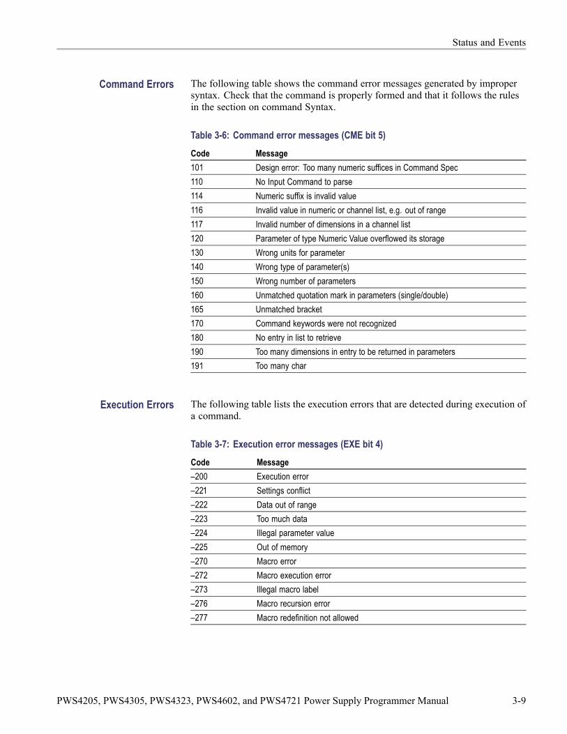
Status and Events
Command Errors The following table shows the command error messages generated by impropersyntax. Check that the command is properly formed and that it follows the rulesin the section on command Syntax.
Table 3-6: Command error messages (CME bit 5)Code Message101 Design error: Too many numeric suffices in Command Spec110 No Input Command to parse114 Numeric suffix is invalid value116 Invalid value in numeric or channel list, e.g. out of range117 Invalid number of dimensions in a channel list120 Parameter of type Numeric Value overflowed its storage130 Wrong units for parameter140 Wrong type of parameter(s)150 Wrong number of parameters160 Unmatched quotation mark in parameters (single/double)165 Unmatched bracket170 Command keywords were not recognized180 No entry in list to retrieve190 Too many dimensions in entry to be returned in parameters191 Too many char
Execution Errors The following table lists the execution errors that are detected during execution ofa command.
Table 3-7: Execution error messages (EXE bit 4)Code Message–200 Execution error–221 Settings conflict–222 Data out of range–223 Too much data–224 Illegal parameter value–225 Out of memory–270 Macro error–272 Macro execution error–273 Illegal macro label–276 Macro recursion error–277 Macro redefinition not allowed
PWS4205, PWS4305, PWS4323, PWS4602, and PWS4721 Power Supply Programmer Manual 3-9

Status and Events
System Errors The following table lists the system errors that can occur during power supplyoperation.
Table 3-8: System error messages (DDE bit 3)Code Message–310 System error–350 Too many errors
Query Errors The following table lists the query errors that can occur during power supplyoperation. These errors may indicate that there was a problem during the queryprocess and that your query will not be performed.
Table 3-9: Query error messages (Standard Event Status Register bit 2)Code Message–400 Query error–410 Query INTERRUPTED–420 Query UNTERMINATED–430 Query DEADLOCKED–440 Query UNTERMINATED
Self Test Errors The following table lists the self test errors that can occur during power supplyoperation.
Table 3-10: Self test error messages (Standard Event Status Register bit 3)Code Message0 No error1 Module Initialization Lost2 Mainframe Initialization Lost3 Module Calibration Lost4 Non-volatile RAM STATE section checksum failed5 Non-volatile RAM RST section checksum failed10 RAM selftest40 Flash write failed41 Flash erase failed80 Digital I/O selftest error
3-10 PWS4205, PWS4305, PWS4323, PWS4602, and PWS4721 Power Supply Programmer Manual

Status and Events
Device Dependent Errors The following table lists the device errors that can occur during power supplyoperation. These errors may indicate that the power supply needs repair.
Table 3-11: Device dependent error messages (DDE bit 3)Code Message220 Front panel uart overrun221 Front panel uart framing222 Front panel uart parity223 Front panel buffer overrun224 Front panel timeout225 Front Crc Check error226 Front Cmd Error401 CAL switch prevents calibration402 CAL password is incorrect403 CAL not enabled404 Computed readback cal constants are incorrect405 Computed programming cal constants are incorrect406 Incorrect sequence of calibration commands407 CV or CC status is incorrect for this command603 FETCH of data that was not acquired604 Measurement overrange
PWS4205, PWS4305, PWS4323, PWS4602, and PWS4721 Power Supply Programmer Manual 3-11

Status and Events
3-12 PWS4205, PWS4305, PWS4323, PWS4602, and PWS4721 Power Supply Programmer Manual

Appendices


Appendix A: ASCII Code Chart
PWS4205, PWS4305, PWS4323, PWS4602, and PWS4721 Power Supply Programmer Manual A-1
Appendix A: ASCII Code Chart
A-2 PWS4205, PWS4305, PWS4323, PWS4602, and PWS4721 Power Supply Programmer Manual
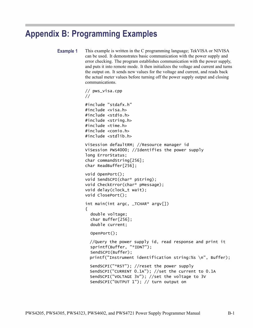
Appendix B: Programming ExamplesExample 1 This example is written in the C programming language; TekVISA or NIVISA
can be used. It demonstrates basic communication with the power supply anderror checking. The program establishes communication with the power supply,and puts it into remote mode. It then initializes the voltage and current and turnsthe output on. It sends new values for the voltage and current, and reads backthe actual meter values before turning off the power supply output and closingcommunications.
// pws_visa.cpp
//
#include "stdafx.h"
#include <visa.h>
#include <stdio.h>
#include <string.h>
#include <time.h>
#include <conio.h>
#include <stdlib.h>
ViSession defaultRM; //Resource manager id
ViSession PWS4000; //Identifies the power supply
long ErrorStatus;
char commandString[256];
char ReadBuffer[256];
void OpenPort();
void SendSCPI(char* pString);
void CheckError(char* pMessage);
void delay(clock_t wait);
void ClosePort();
int main(int argc, _TCHAR* argv[])
{
double voltage;
char Buffer[256];
double current;
OpenPort();
//Query the power supply id, read response and print it
sprintf(Buffer, "*IDN?");
SendSCPI(Buffer);
printf("Instrument identification string:%s \n", Buffer);
SendSCPI("*RST"); //reset the power supply
SendSCPI("CURRENT 0.1A"); //set the current to 0.1A
SendSCPI("VOLTAGE 3V"); //set the voltage to 3V
SendSCPI("OUTPUT 1"); // turn output on
PWS4205, PWS4305, PWS4323, PWS4602, and PWS4721 Power Supply Programmer Manual B-1

Appendix B: Programming Examples
voltage=5.0;
current=0.2;
printf("Setting voltage(V) & current(A): %f,%f \n",
voltage, current);
ErrorStatus = viPrintf(PWS4000,"VOLT %f\n",voltage); //set
the output voltage
CheckError("Unable to set voltage");
ErrorStatus = viPrintf(PWS4000,"CURRENT %f\n",current);
//set the output current
CheckError("Unable to set current");
ErrorStatus = viPrintf(PWS4000,"MEASURE:VOLTAGE?\n");
//measure the output voltage
CheckError("Unable to write the device");
ErrorStatus = viScanf(PWS4000,"%f",&voltage); //retrieve
reading
CheckError("Unable to read voltage");
ErrorStatus = viPrintf(PWS4000,"MEASURE:CURRENT?\n");
//measure the output current
CheckError("Unable to write the device");
ErrorStatus = viScanf(PWS4000,"%f",¤t); //retrieve
reading
CheckError("Unable to read current");
printf("Measured voltage(V) & current(A): %f,%f \n",
voltage, current);
SendSCPI("OUTPUT 0"); //turn output off
ClosePort();
while(1);
//return 0;
}
void OpenPort()
{
//Open communication session with the power supply, and
put the power supply in remote
ErrorStatus = viOpenDefaultRM(& defaultRM);
ErrorStatus =viOpen(defaultRM,
"USB0::0X0699::0X0391::006002206573001001::INSTR",0,0,&PWS4000);
CheckError("Unable to open the port");
SendSCPI("SYSTEM:REMOTE");
}
void SendSCPI(char* pString)
{
B-2 PWS4205, PWS4305, PWS4323, PWS4602, and PWS4721 Power Supply Programmer Manual

Appendix B: Programming Examples
char* pdest;
strcpy(commandString,pString);
strcat(commandString, "\n");
ErrorStatus = viPrintf(PWS4000, commandString);
CheckError("Can't Write to Power Supply");
pdest = strchr(commandString, '?'); //Search for query
command
if (pdest != NULL)
{
ErrorStatus = viBufRead(PWS4000, (ViBuf)ReadBuffer,
sizeof(ReadBuffer), VI_NULL);
CheckError("Can't read from driver");
strcpy(pString, ReadBuffer);
}
}
void ClosePort()
{
viClose(PWS4000);
viClose(defaultRM);
}
void CheckError(char* pMessage)
{
if(ErrorStatus != VI_SUCCESS)
{
printf("\n %s",pMessage);
ClosePort();
exit(0);
}
}
void delay(clock_t wait)
{
clock_t goal;
goal = wait + clock();
while(goal > clock());
}
PWS4205, PWS4305, PWS4323, PWS4602, and PWS4721 Power Supply Programmer Manual B-3

Appendix B: Programming Examples
Example 2 This example shows a command sequence that configures a three-step list toexecute once in continuous mode. It saves the list in location 1, and then placesthe instrument in list mode and runs the list.
SYSTEM:REMOTE
*RST
TRIGGER:SOURCE BUS
LIST:MODE CONT
LIST:COUNT ONCE
LIST:STEP 3
LIST:VOLT 1,2V
LIST:CURRENT 1,1.0A
LIST:WIDTH 1,5s
LIST:VOLT 2,4V
LIST:CURRENT 2,1.0A
LIST:WIDTH 2,10s
LIST:VOLT 3,0V
LIST:CURRENT 3,0.1A
LIST:WIDTH 3,2s
LIST:SAVE 1
FUNCTION:MODE LIST
OUTPUT ON
TRIGGER IMMEDIATE
Example 3 This example shows a command sequence that configures a two-step list toexecute 20 times. It saves the list in location 1, and then places the instrumentin list mode and runs the list.
SYSTEM:REMOTE
*RST
TRIGGER:SOURCE BUS
LIST:MODE CONT
LIST:COUNT 20
LIST:STEP 2
B-4 PWS4205, PWS4305, PWS4323, PWS4602, and PWS4721 Power Supply Programmer Manual

Appendix B: Programming Examples
LIST:VOLTAGE 1,5V
LIST:CURRent 1,1.0A
LIST:WIDTH 1,10s
LIST:VOLTAGE 2,5.5V
LIST:CURRent 2,1.0A
LIST:WIDTH 2,5s
LIST:SAVE 1
FUNCTION:MODE LIST
OUTPUT ON
TRIGGER:IMMEDIATE
Example 4 This example is written in the C programming language; TekVISA or NIVISAcan be used. The program demonstrates setting up and executing a list. It showshow to use the Operation Condition Register to determine when the list hasfinished executing.
// pws_visa.c
//
#undef MICROSOFT // Change this to #define if Microsoft
#ifdef MICROSOFT
#include “stdafx.h”
#include <conio.h>
#else
typedef char_TCHAR;
#endif
#include <visa.h>
#include <stdio.h>
#include <string.h>
#include <time.h>
#include <stdlib.h>
ViSession defaultRM; //Resource manager id
ViSession PWS4000; //Identifies the power supply
long ErrorStatus;
char commandString[256];
char ReadBuffer[256];
//
// Some compilers do not require that void arguments be
declared, however, all should accept declaration of
// void argument lists.
//
PWS4205, PWS4305, PWS4323, PWS4602, and PWS4721 Power Supply Programmer Manual B-5
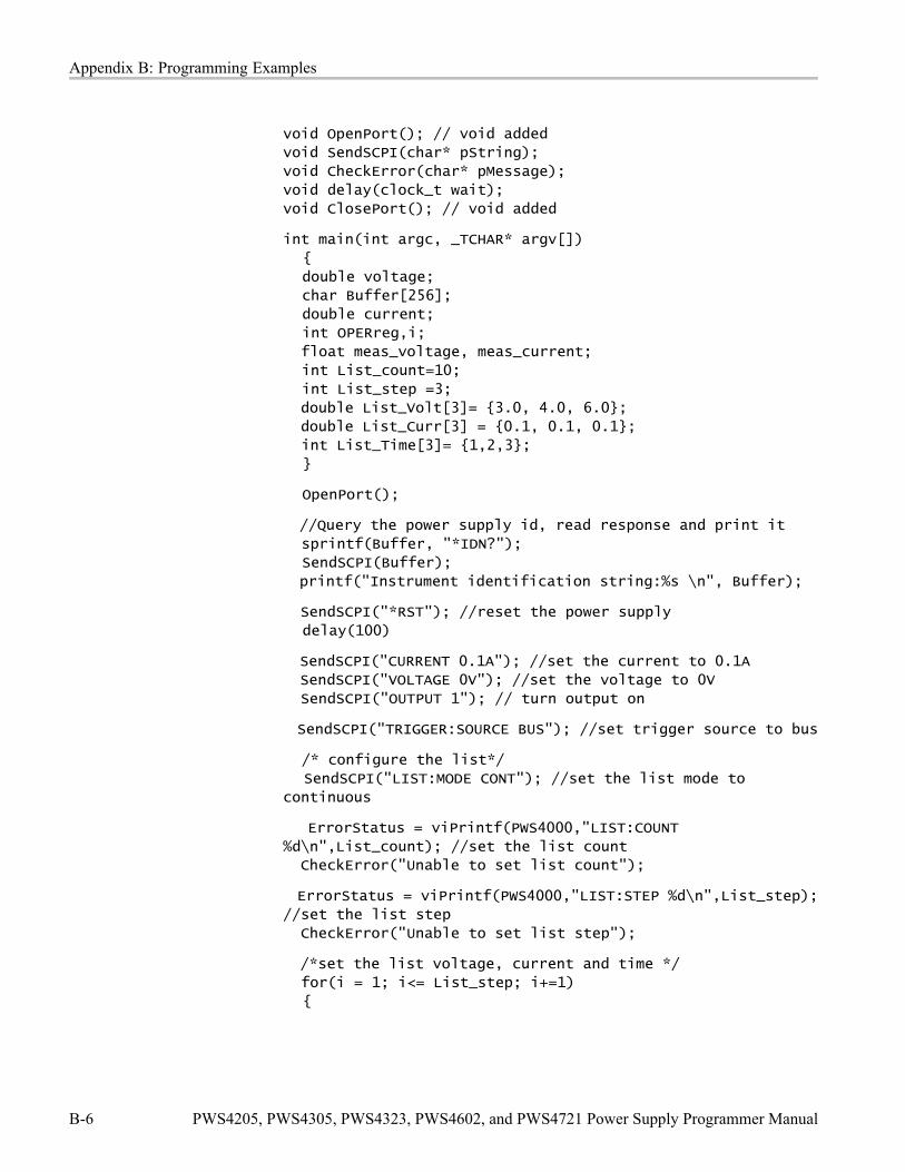
Appendix B: Programming Examples
void OpenPort(); // void added
void SendSCPI(char* pString);
void CheckError(char* pMessage);
void delay(clock_t wait);
void ClosePort(); // void added
int main(int argc, _TCHAR* argv[])
{
double voltage;
char Buffer[256];
double current;
int OPERreg,i;
float meas_voltage, meas_current;
int List_count=10;
int List_step =3;
double List_Volt[3]= {3.0, 4.0, 6.0};
double List_Curr[3] = {0.1, 0.1, 0.1};
int List_Time[3]= {1,2,3};
}
OpenPort();
//Query the power supply id, read response and print it
sprintf(Buffer, "*IDN?");
SendSCPI(Buffer);
printf("Instrument identification string:%s \n", Buffer);
SendSCPI("*RST"); //reset the power supply
delay(100)
SendSCPI("CURRENT 0.1A"); //set the current to 0.1A
SendSCPI("VOLTAGE 0V"); //set the voltage to 0V
SendSCPI("OUTPUT 1"); // turn output on
SendSCPI("TRIGGER:SOURCE BUS"); //set trigger source to bus
/* configure the list*/
SendSCPI("LIST:MODE CONT"); //set the list mode to
continuous
ErrorStatus = viPrintf(PWS4000,"LIST:COUNT
%d\n",List_count); //set the list count
CheckError("Unable to set list count");
ErrorStatus = viPrintf(PWS4000,"LIST:STEP %d\n",List_step);
//set the list step
CheckError("Unable to set list step");
/*set the list voltage, current and time */
for(i = 1; i<= List_step; i+=1)
{
B-6 PWS4205, PWS4305, PWS4323, PWS4602, and PWS4721 Power Supply Programmer Manual
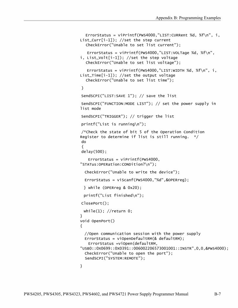
Appendix B: Programming Examples
ErrorStatus = viPrintf(PWS4000,"LIST:CURRent %d, %f\n", i,
List_Curr[i-1]); //set the step current
CheckError("Unable to set list current");
ErrorStatus = viPrintf(PWS4000,"LIST:VOLTage %d, %f\n",
i, List_Volt[i-1]); //set the step voltage
CheckError("Unable to set list voltage");
ErrorStatus = viPrintf(PWS4000,"LIST:WIDTH %d, %f\n", i,
List_Time[i-1]); //set the output voltage
CheckError("Unable to set list time");
}
SendSCPI("LIST:SAVE 1"); // save the list
SendSCPI("FUNCTION:MODE LIST"); // set the power supply in
list mode
SendSCPI("TRIGGER"); // trigger the list
printf("List is running\n");
/*Check the state of bit 5 of the Operation Condition
Register to determine if list is still running. */
do
{
delay(500);
ErrorStatus = viPrintf(PWS4000,
"STATus:OPERation:CONDition?\n");
CheckError("Unable to write the device");
ErrorStatus = viScanf(PWS4000,"%d",&OPERreg);
} while (OPERreg & 0x20);
printf("List finished\n");
ClosePort();
while(1); //return 0;
}
void OpenPort()
{
//Open communication session with the power supply
ErrorStatus = viOpenDefaultRM(& defaultRM);
ErrorStatus =viOpen(defaultRM,
"USB0::0X0699::0X0391::006002206573001001::INSTR",0,0,&PWS4000);
CheckError("Unable to open the port");
SendSCPI("SYSTEM:REMOTE");
}
PWS4205, PWS4305, PWS4323, PWS4602, and PWS4721 Power Supply Programmer Manual B-7

Appendix B: Programming Examples
void SendSCPI(char* pString)
{
char* pdest;
strcpy(commandString,pString);
strcat(commandString, "\n");
ErrorStatus = viPrintf(PWS4000, commandString);
CheckError("Can't Write to Power Supply");
pdest = strchr(commandString, '?'); //Search for query
command
if (pdest != NULL)
{
ErrorStatus = viBufRead(PWS4000, (ViBuf)ReadBuffer,
sizeof(ReadBuffer), VI_NULL);
CheckError("Can't read from driver");
strcpy(pString, ReadBuffer);
}
}
void ClosePort()
{
viClose(PWS4000);
viClose(defaultRM);
}
void CheckError(char* pMessage)
{
if(ErrorStatus != VI_SUCCESS)
{
printf("\n %s",pMessage);
ClosePort();
exit(0);
}
}
void delay(clock_t wait)
{
clock_t goal;
goal = wait + clock();
while(goal > clock());
}
B-8 PWS4205, PWS4305, PWS4323, PWS4602, and PWS4721 Power Supply Programmer Manual
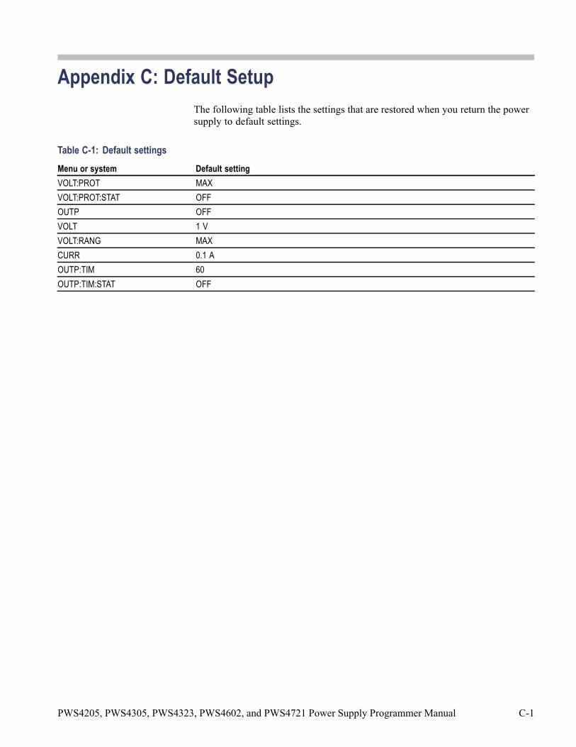
Appendix C: Default SetupThe following table lists the settings that are restored when you return the powersupply to default settings.
Table C-1: Default settingsMenu or system Default settingVOLT:PROT MAXVOLT:PROT:STAT OFFOUTP OFFVOLT 1 VVOLT:RANG MAXCURR 0.1 AOUTP:TIM 60OUTP:TIM:STAT OFF
PWS4205, PWS4305, PWS4323, PWS4602, and PWS4721 Power Supply Programmer Manual C-1

Appendix C: Default Setup
C-2 PWS4205, PWS4305, PWS4323, PWS4602, and PWS4721 Power Supply Programmer Manual

Index
AASCII, 2-1
code chart, A-1
BBNF (Backus Naur form), 2-1
C*CLS, 2-13Command and Query Structure, 2-1Command Groups, 2-7Command syntax,
BNF (Backus Naur form), 2-1Command,
syntax, 2-1syntax:BNF (Backus Naur form), 2-1
CONFigure:SOUNd[:STATe], 2-14
E*ESE, 2-14*ESR?, 2-15Event handling, 3-1
FFETCh:CURRent[:DC]?, 2-15FETCh:VOLTage[:DC]?, 2-16FETCh[:SCALar]:POWer?, 2-16
GGPIBUsb:ADDress?, 2-17GPIBUsb:ID?, 2-17
I*IDN?, 2-17IEEE Std. 488.2-1987, 2-1
MMEASure:CURRent[:DC]?, 2-18MEASure:VOLTage[:DC]?, 2-18
Message,handling, 3-1
O*OPC, 2-19
P*PSC, 2-19
R*RCL, 2-20*RST, 2-20
S*SAV, 2-21[SOURce:]CURRent[:LEVel], 2-21[SOURce:]DIGital:DATA, 2-22[SOURce:]DIGital:FUNCtion, 2-23[SOURce:]FUNCtion:MODE, 2-24[SOURce:]LIST:COUNt, 2-24[SOURce:]LIST:CURRent[:LEVel], 2-25[SOURce:]LIST:MODE, 2-26[SOURce:]LIST:RCL, 2-26[SOURce:]LIST:SAVe, 2-27[SOURce:]LIST:STEP, 2-27[SOURce:]LIST:VOLTage[:LEVel], 2-28[SOURce:]LIST:WIDth, 2-28[SOURce:]OUTPut:DFI:SOURce, 2-29[SOURce:]OUTPut:PON[:STATe], 2-29[SOURce:]OUTPut:PROTection:CLEar, 2-30[SOURce:]OUTPut:RI:MODE, 2-30[SOURce:]OUTPut:TIMer:DELay, 2-32[SOURce:]OUTPut:TIMer[:STATe], 2-32[SOURce:]OUTPut[:STATe], 2-31[SOURce:]VOLTage:PROTection:STATe, 2-35[SOURce:]VOLTage:PROTection[:LEVel], 2-34[SOURce:]VOLTage:RANGe, 2-35[SOURce:]VOLTage[:LEVel], 2-33*SRE, 2-36Status and error commands, 2-7Status, 3-1STATus:OPERation:CONDition?, 2-37
PWS4205, PWS4305, PWS4323, PWS4602, and PWS4721 Power Supply Programmer Manual Index-1

Index
STATus:OPERation:ENABle, 2-37STATus:OPERation[:EVENt]?, 2-38STATus:QUEStionable:CONDition?, 2-38STATus:QUEStionable:ENABle, 2-39STATus:QUEStionable:NTRansition, 2-40STATus:QUEStionable:PTRansition, 2-41STATus:QUEStionable[:EVENt]?, 2-40*STB?, 2-41Syntax,
BNF (Backus Naur form), 2-1command, 2-1
SYSTem:ERRor?, 2-42SYSTem:KEY, 2-42SYSTem:LOCal, 2-43
SYSTem:POSetup, 2-44SYSTem:REMote, 2-44SYSTem:RWLock, 2-45SYSTem:VERSion?, 2-45
T*TRG, 2-45TRIGger:SOURce, 2-46TRIGger[:IMMediate], 2-46*TST?, 2-47
W*WAI, 2-47
Index-2 PWS4205, PWS4305, PWS4323, PWS4602, and PWS4721 Power Supply Programmer Manual