pvm 100 operating guide - spectrum...
TRANSCRIPT

Piezoelectric Vibration Meter PVM 100
Operating Guide
Piezoelectric Vibration MeterPVM 100
Operating Guide
For product information or technical assistance, contact: Wilcoxon Research 21 Firstfield Road, Gaithersburg, MD 20878 USA 1-800-WILCOXON 301-330-8811 Fax: 301-330-8873 Email: [email protected] Internet: http://www.wilcoxon.com

Contents
1.0 Theory of Operation ................................................................................................................3 1.1 Acceleration, Velocity, and Displacement Terms and Expressions ................................................................3 1.2 Rotational Vibration Relationships .................................................................................................................3 1.3 Peak, RMS, and Peak-to-Peak.........................................................................................................................4 2.0 Product Description.................................................................................................................5 2.1 Front Panel ......................................................................................................................................................5 2.2 Top Edge .........................................................................................................................................................6 2.3 Bottom Edge....................................................................................................................................................6 2.4 PVM 100 Meter Circuit...................................................................................................................................6 2.5 Accelerometer, Cable, Magnet, and Probe Tip................................................................................................7 3.0 Setup for Use ............................................................................................................................7 3.1 Installing the Battery .......................................................................................................................................7 3.2 Connecting the Accelerometer ........................................................................................................................8 3.3 Powering..........................................................................................................................................................8 4.0 Operation ..................................................................................................................................8 4.1 Acceleration Mode ..........................................................................................................................................8 4.2 Velocity Mode.................................................................................................................................................9 4.3 Displacement Mode.........................................................................................................................................9 4.4 Taking a Reading.............................................................................................................................................9 4.5 Powering OFF .................................................................................................................................................9 5.0 Maintenance and Troubleshooting.........................................................................................9 5.1 Calibration and Adjustments ...........................................................................................................................9 5.1.1 Calibration Using a Reference Accelerometer on a Vibration Exciter .........................................................9 5.1.2 Calibration Using a Signal Generator.........................................................................................................10 5.1.3 Calibration Using a Signal Generator.........................................................................................................10 5.2 Maintenance ..................................................................................................................................................10 5.3 Troubleshooting.............................................................................................................................................11 Table 1 – Troubleshooting Chart....................................................................................................................11 6.0 Warranty ................................................................................................................................12 7.0 Technical Assistance ..............................................................................................................12 7.1 Technical Assistance .....................................................................................................................................12 7.2 Customer Service ..........................................................................................................................................12 Appendix A, Functional block diagram.....................................................................................13 Appendix B, Vibration Units and Conversions.........................................................................14
97016, Rev.B 9/05 page 2

1.0 Theory of Operation 1.1 Acceleration, Velocity, and Displacement Terms and Expressions Displacement is always expressed in terms of a distance measurement such as inches, feet, or meters. Displacement terms of mils (0.001 inch) or millimeters (0.001 meter) are also used to express displacement.
When an object moves, it is changing its position at some rate of change. The rate of change is velocity and is expressed in terms of a distance per unit of time such as inches per second, feet per minute, or meters per second. These terms are often expressed more in their mathematical sense as inches/second (in/sec), feet/minute (ft/min), or meters/second (m/sec). Just like displacement, other units of displacement per unit of time are also used, such as the metric millimeters per second (mm/sec). The term “in/sec” usually is expressed “i.p.s.” or “ips.” If an object is changing its velocity, then it is said to be accelerating.
An object at resbeing subject toused for the acc at sea level are,in/sec2 , or 9.806the accelerationsmall “g” standsuse of the smallamong scientistunits of a gram. acceleration is athe acceleration
Acceleration is a rate of change of velocity per unit of time such as “velocity” per second or “velocity” per minute. Instead of using the velocity “word”, we can substitute the velocity term such as “inches per second” per second. “Inches per second per second” can be mathematically stated as (inches/second)/second. Algebraic manipulation of the term “(inches/second)/second” results in re-stating the expression as inches per second squared or, more simply, inches/second2. These expressions are often shortened even further to in/s2 (English units) or m/s2 (metric units).
1.2 Rotational Vibration Relationships When acceleration, velocity and displacement measurements involvemovement. However, when the movement is cyclical, then events aremust be taken into account when measuring acceleration, velocity anusually characterized as periodic, as they repeat over some period. Pereferred to as cyclical, meaning they have cycles of repetition. A comcycles per minute (CPM) or cycles per second (CPS). A scientificallyis Hertz, named after Heinrich R. Hertz, a German physicist, and com
When measurements of rotational vibration are made, the rotating spaccount. Rotating shafts of machine have their rate of rotation measutime. This is an expression of the frequency of the rotation. One termminute, usually shortened to RPM. The more general term of CPM israte of machinery.
In mathematics, frequency is also expressed as radians. A radian is arelated to the distance around the periphery (circumference) of a circcircle is 2π times the radius, where π is a transcendental (non-repeatiapproximately, 3.14159265 and often used in physical calculations inrotational mathematics all rotation angles are expressed in radians, wradians. Further, the term used for frequency in rotating mathematics
97016, Rev.B 9/05 page 3
The Meaning of “g”
t on the surface of the earth is always the acceleration of gravity. The values eleration of the earth’s gravity averaged variously: 32.1742 ft/sec2 , 386.09 7 m/sec2 . The common term used for
of the earth’s gravity is 1g, where the for the “gravitational” acceleration. The “g” sometimes causes slight confusion s as the small “g” is also used for the However, the use of the “g” for g’s of ccepted as the common expression for of the earth’s gravity.
lineal movement, there is no cyclical repetitive and a new term, frequency, d displacement. Repetitive events are riodic events are sometimes also mon way to refer to such events is in accepted term for cycles per second monly abbreviated as “Hz”.
eed of the machine must be taken into red in terms of rotations per unit of in common use is revolutions per also used to express the rotational
measure of the angle of rotation and is le. In geometry, the circumference of a ng) decimal number valued at, a rounded form as 3.1416. In here one rotation is equal to 2π is ω, where ω = 2πf and f is the

frequency in Hz. All rotational time units are functions of ω, and ω relates the rotating angle to units of seconds (Hz).
All of the above mathematical terms are necessary to understand how one converts rotating vibration measures from one quantity to another. Acceleration can be converted to velocity and to displacement by the operation of the mathematics of rotating vibration relationships. Knowing any one quantity of vibration and the frequency of that vibration allows the user to convert that unit to any of the other units of vibration. So, knowing the acceleration, the velocity, or the displacement along with the frequency, any user can convert that vibration to any other vibrational unit.
In section 1.1 it was noted that the rate of change of displacement was velocity. The term “rate of change” in mathematics is equivalent to the operation of differentiation. When one mathematical relationship can be derived from another by differentiation and that relationship is linear (defined in mathematics as being a continuous function rather than discontinuous), then the mathematical operation of integration can also be used between the relationships. Applying this to vibration means that if velocity, as a function of time, can be derived from a displacement time-based function by differentiation, then displacement can be derived from velocity by integration. For time-varying vibration signals, this is true. It is also true for the relationship between acceleration and velocity.
Consequently, if we have a time-varying signal of acceleration, we can integrate that signal to obtain the time-varying velocity of vibration. We can also continue and integrate the velocity to obtain the displacement. Without going into all the specifics of the derivation, we will state here that the relationship between acceleration and velocity is: A = 2πf V, where A is acceleration, f is the frequency, and V is the velocity. Conversely, the equation converts velocity to acceleration where V = A / 2πf.
NOTE: All units in this equation must be dimensionally consistent. If A is in/sec2 then V must be in terms of in/sec. In metric units A would be m/sec2 and V would be m/sec.
If we wanted to convert g’s of acceleration to in/sec2, the g’s of acceleration must be multiplied by 386.09 to get the proper number for the acceleration in in/sec2. If we already had the vibration in terms of inches/second2 of acceleration, then it must be divided by 386.09 to get its value in g’s.
Displacement and velocity are related by the same kind of equations. V = 2πf D, and D = V / 2πf. Again, the units must be dimensionally consistent when using the equation. Appendix B contains information regarding the equations and unit conversions.
1.3 Peak, RMS, and Peak-to-Peak Acceleration is typically measured in peak values of acceleration while velocity is usually measured in root-mean-squared (RMS) units. Displacement has traditionally been measured as peak-to-peak.
The acceleration of an object multiplied by its mass yield the amount of force applied to that object to accelerate it. Sir Isaac Newton (1642-1727) established this relationship in his second law of motion. Vibration analysts generally want to know the peak value of vibration as it relates most closely to the peak forces generated by rotating machinery. Since large forces can cause damage to machines, these analysts are, quite naturally, interested in knowing the maximum accelerations of machines.
Figure 1.3.1 - Relationship of Peak, RMS, and Peak-to-Peak
Since the kinetic energy (energy of motion) of an object is related to the square of the object’s velocity, many vibration analysts prefer to use velocity as the measure of choice for vibration severity. In electronics, the total energy of an electronic signal is described by its root-mean-squared (RMS) value. Combining these two preferences many vibration analysts prefer to measure the vibration energy of a machine by using the RMS value of velocity. ISO 10816 also uses the RMS velocity of vibration as the measure for severity of machine vibration.
97016, Rev.B 9/05 page 4

Displacement evolved as a vibration measure because of the necessity to know the shaft motion in oil-lubricated journal bearings. These bearings are designed with very tight tolerances and often have no more than 10 mils (0.25 mm) of total clearance in the bearing housing. Don Bently pioneered a measurement technique using a principle of eddy currents to measure the gap between the eddy current probe tip and a rotating shaft. These became known as proximity probes (prox probes) and prove very useful for bearing diagnostic and condition monitoring in journal-bearing supported machines. Since the total clearance of these bearings represents a physical limit to the amount of motion that can be tolerated, it is very important to be able to measure the peak-to-peak (P-P) motion of the shaft with the prox probe. Consequently, displacement measurements have traditionally used the peak-to-peak (P-P) values when reporting displacement measurements.
ENGLISH METRIC Figure 1.3.2 - PVM100 vibration units and measures on front panel
NOTE: The PVM 100 performs all the conversions for the user when making measurements. The front panel of the PVM 100 notes the units and measurement types for the vibration levels displayed.
2.0 Description The PVM 100 is a precision vibration meter with a 3-½ digit digital display. The PVM 100 meter uses an external Integrated Electronics Piezoelectric (IEPE) accelerometer for measurements. The accelerometer is powered by the PVM 100 meter at a nominal constant current of 3 mA. The meter has internal integrator circuits to develop velocity or displacement measurements from the acceleration signal. The 3-½ digit digital display auto-ranges to yield the highest precision in the measurement. At any time the user can “freeze” the reading on the display by depressing and holding the FUNCTION HOLD button on the PVM 100.
Figure 2.1 - Front Panel and battery compartment description
2.1 Front Panel The display and all operating switches are on the front face of the PVM 100. The central feature of the front face is the 3-½ digit digital display. It will display measurement values using digits numbered between 0 and 1999. It has a “floating” decimal point that can be set at positions between digits. The full-scale numeric value can read 1.999, 19.99, 199.9, or 1999.
The measurement types are also printed on the front face. Acceleration is measured in m/s2 or g (peak), velocity is measured in mm/s or ips (RMS), and displacement is measured in mm or mil (P-P).
The display is of the Liquid Crystal Display (LCD) type. It will display the vibration readings continuously by updating readings. The LCD also has a display for a “low battery voltage” condition. If the battery voltage is insufficient to support proper operation, the LCD will display a “BATT” in its lower left corner.
The “POWER (ON/OFF)” button is an alternate-action latching pushbutton. Depressing it will power up the PVM 100 to “ON” and the button will remain depressed. Pressing “POWER (ON/OFF)” while the PVM 100 is “ON” will cause the button to unlatch and power the PVM 100 “OFF”.
97016, Rev.B 9/05 page 5

Below the POWER pushbutton is the “FUNCTION / HOLD” button.
When this button is depressed momentarily it indexes the measurement for a reading (FUNCTION operation). The arrow to the right of the display will move from “m/s2 or g” (selects acceleration ‘peak’) to “mm/s or ips” (selects velocity ‘rms’) to “mm or mil” (selects displacement ‘peak-to-peak’) and then back to “m/s2 or g” again.
Pressing and holding the pushbutton places the PVM 100 into the “HOLD” mode. It is a momentary pushbutton, it does not latch. Depressing and holding the “FUNCTION/HOLD” will cause the display to “freeze” displaying the last reading taken when the button was depressed. Upon releasing the “HOLD” button, the display will return to instantaneous updating display readings.
2.2 Top Edge The top of the PVM 100 has two connector sockets.
Near the upper middle of the PVM 100 is a 3.5mm mini phone plug labeled “OUTPUT” that connects to the output of the high-pass filter section of the circuit. The output impedance of this connection is approximately 1 KΩ. This is the location where a voltmeter must be connected to calibrate the PVM 100. This output signal may also be connected to an external audio amplifier allowing the operator to “listen” to the vibration signal.
NOTE: Amplification is necessary because the output signal power is too low to drive headphones or a speaker directly.
On the upper right side is a BNC connector. It is labeled “INPUT” and is where the IEPE accelerometer connects. The BNC mating connector is a coaxial quarter-turn locking connector. The 3 mA, nominal, current supply to power the IEPE accelerometer is supplied out this connector.
2.3 Bottom Edge The bottom of the PVM 100 contains the battery compartment. This compartment may be opened by pressing on the cover in the direction marked by the “OPEN” arrow until the cover releases. The PVM 100 uses a 9-Volt battery for power. An Energizer 522 or Duracell MN1604 can be used for powering the PVM 100.
Inside the battery compartment are the two calibration adjustment potentiometers. Do not make any adjustments to the potentiometers unless performing a calibration adjustment as per the calibration procedure described in section 5.1 of this manual.
To close the cover, place the cover tab into the slot and rotate the cover down into position, then snap the cover closed.
Figure 2.3 - Battery compartment access
2.4 PVM 100 Meter Circuit
NOTE: Appendix A shows the block diagram of the PVM 100 meter circuit.
The IEPE accelerometer contains an internal electronic amplifier. It requires at least 18 Volts of power supplied through a constant-current diode and applied to its signal pin. The IEPE accelerometer output signal appears as an AC signal “riding” on a DC voltage at the terminals of the accelerometer. The PVM 100 input signal conditioner provides the power for the accelerometer, the AC-coupling of the vibration signal, and a buffer amplifier to drive the first integrator amplifier. The gain adjusting potentiometer (trimpot) is within the circuit.
97016, Rev.B 9/05 page 6

The output of the signal conditioning circuit is applied to two integration amplifiers in series. The signal conditioner output and the outputs of each integration stage are routed to a selector switch. The switch determines whether the measurement will be acceleration, velocity, or displacement. The selected vibration signal passes through a high-pass filter. The high-pass filter acts to limit the measurement instability that would result if the measurement circuit frequency response were too low.
The output of the high-pass filter is applied to the rectifier/smoothing amplifier. This circuit converts the bipolar signal to one that is only positive and then provides for an averaging time-constant to smooth the signal for measurement. Within this circuit is the zero setting adjustment potentiometer (trimpot).
NOTE: The GAIN and ZERO potentiometers should only be adjusted as part of a calibration procedure.
The Analog-to-Digital (A/D) converter circuit measures the output of the smoothing circuit. When the user depresses the HOLD button, the A/D converter measurement will “freeze” and allows the user to hold that measurement on the display as long as the HOLD button remains depressed.
2.5 Accelerometer, Cable, Magnet, and Probe Tip CABLE B3 SF6 PVM 100 784A PT2
The PVM 100 is supplied with the accessories shown.
The cable connects the 784A accelerometer to the input BNC connector.
The PT2 is useful for quick measurements of vibration up to 500 Hz and screws to the 784A.
The 784A can be attached to the B3 magnet for measurements up to 2 kHz.
The SF6 should be used when it is desired to measure vibration up to 10 kHz. The SF6 is screwed into the base of the 784A and attached to the structure to be measured into a mating ¼-28 threaded hole. Figure 2.5 - PVM 100 & accessories
3.0 Setup for Use 3.1 Installing the Battery 1. Open the battery compartment by pressing on the cover in the direction marked by the “OPEN” arrow
until the cover releases.
2. Remove the cover. The PVM 100 uses a 9-Volt battery for power. An Energizer 522, Duracell MN1604, or similar 9-volt battery, can be used for powering the PVM 100.
3. Snap the battery into the mating battery connector located in the compartment. Place the battery and connecting wire back into the compartment. Exercise care to insure the wire will not be pinched by the cover when it is replaced.
4. To close the cover, place the cover tab into the slot and rotate the cover down into position, then snap the cover closed.
97016, Rev.B 9/05 page 7

3.2 Connecting the Accelerometer The accelerometer supplied with the PVM 100 is a Wilcoxon Model 784A. It has accessories of a stud mount (SF6), probe tip (PT2), and magnet (B3). A cable (R6-2-J5A-6) is supplied to connect the 784A to the PVM 100 BNC input connector.
NOTE: Other Wilcoxon IEPE accelerometers can also be used with the PVM 100. The accelerometer must have a nominal design sensitivity of 100 mV/g (10.2 mV/m/sec2).
Connect the 2-pin MIL-style connector of the cable to the 784A.
Connect the BNC end of the cable to the PVM 100 BNC input connector and turn it until the connector locks into place.
Install the probe tip by screwing it into the base of the 784A, or attach the magnet to the 784A using its integral ¼-28 stud. The 784A may be directly attached to a structure by using the ¼ -28 mounting stud (SF6) and threading the stud into a prepared ¼-28 hole in the structure and attaching the 784A to the stud.
3.3 Powering Depress the “POWER (ON/OFF)” button located on the PVM 100 left side. Observe that the “BATT” display on the LCD does not illuminate.
Insure the display is functioning by observing that readings are displayed and updating on the meter panel.
The PVM 100 is now ready for use.
4.0 Operation With power applied to the PVM 100, the front panel LCD meter will display the level of the overall vibration. The passband of the overall vibration level varies according to the type of measurement.
Each time the “FUNCTION / HOLD” button is depressed and released, the PVM 100 will step to the next vibration measurement parameter. When initially powered the PVM 100 will be in the acceleration mode. Pushing and releasing the “FUNCTION / HOLD” button will advance the PVM 100 to the velocity mode. Pushing and releasing the “FUNCTION / HOLD” button again will advance the PVM 100 to the displacement mode. If the “FUNCTION / HOLD” button is depressed and released again, the PVM 100 will cycle back to the acceleration mode.
4.1 Acceleration Mode In the acceleration mode the PVM 100 will measure the vibration in terms of the m/s2 or g’s of vibration. The measurement will be scaled for the equivalent peak acceleration level based on the RMS value of acceleration (1.414 times RMS). The arrow on the right side of the screen will be pointing at the “m/s2 or g” to indicate the PVM 100 is in the acceleration mode and measuring in “m/s2” or “g”of acceleration.
Figure 4.0 - Examples of the display for Acceleration, Velocity, and Displacement of the English and Metric unit models.
97016, Rev.B 9/05 page 8

4.2 Velocity Mode In the velocity mode the PVM 100 will measure the vibration in terms of the velocity (in mm/s or ips). The measurement will be scaled for the RMS value of velocity measured. The arrow on the right side of the screen will be pointing at the “mm/s or ips” to indicate the PVM 100 is in the velocity mode and measuring in “mm/s” or “ips” of velocity.
4.3 Displacement Mode In the displacement mode the PVM 100 will measure the vibration in terms of the displacement of vibration. The measurement will be scaled for the equivalent peak-to-peak displacement level based on the RMS value of acceleration (2.828 times RMS). The arrow on the right side of the screen will be pointing at the “mm or mils” to indicate the PVM 100 is in the acceleration mode and measuring in “mm” or “mils” of displacement.
4.4 Taking a Reading Depressing and holding the “FUNCTION / HOLD” button will cause the PVM 100 to ‘freeze’ the display and hold the last reading. This will allow a user to make note of the reading of the vibration level.
Releasing the “FUNCTION / HOLD” button will allow the PVM 100 to continue taking new readings.
4.5 Powering OFF To turn off power to the PVM 100, depress the “POWER (ON/OFF)” button. The LCD display will clear, indicating the power is now “OFF” for the PVM 100.
NOTE: Exercise caution when storing the PVM 100 as it is possible to accidentally cause the power to be applied if the PVM 100 has anything heavy resting against the front panel.
5.0 Maintenance and Troubleshooting 5.1 Calibration and Adjustments
5.1.1 Calibration Using a Reference Accelerometer on a Vibration Exciter Attach the accelerometer of the PVM 100 to the reference accelerometer.
Insert a mini phone plug with a short cable into the jack labeled OUTPUT on the top of the PVM 100. Connect an RMS-reading voltmeter to this cable.
Open the battery compartment at the bottom of the PVM 100.
Remove the battery from the compartment to expose the potentiometer labeled GAIN, but do not disconnect the battery from its connector.
Depress the POWER (ON/OFF) button to turn on power to the PVM 100, turn on power to the voltmeter.
Turn on the vibration exciter and set the vibration frequency to 100 Hz and the amplitude to 10 g, peak (7.07 g, rms) for PVM100’s supplied with English unit scaling. For metric scales units, set the input frequency to 100 Hz and the amplitude to 100 m/sec2, peak (7.07 m/sec2, rms)
Adjust the GAIN potentiometer inside the battery compartment until the voltmeter reads 0.707 Vrms (2 Volts, peak-to-peak).
97016, Rev.B 9/05 page 9

Confirm that the LCD front panel display reads 10 g’s, on English unit scaled PVM100’s, or 100 m/sec2 on the Metric unit scaled PVM100’s (± 3% of reading, ± 1 digit).
Turn power to the vibration exciter off, set the PVM 100 power to OFF, turn off power to the voltmeter, replace the battery in its compartment and snap the cover closed.
5.1.2 Calibration Using a Signal Generator Attach the calibration adapter circuit to the input of the PVM 100. Connect a signal generator to the input of the calibration circuit.
NOTE: The calibration circuit must be constructed and supplied by the user. This adapter circuit is not available from Wilcoxon Research.
Figure 5.1.2 - Schematic of Calibration Adapter
Insert a mini phone plug with a short cable into the jack labeled OUTPUT on the top of the PVM 100. Connect an RMS-reading voltmeter to this cable.
Open the battery compartment at the bottom of the PVM 100.
Remove the battery from the compartment to expose the potentiometer labeled GAIN, but do not disconnect the battery from its connector.
Depress the POWER (ON/OFF) button to turn on power to the PVM 100, turn on power to the voltmeter, turn on power to the signal generator.
Set the frequency of the signal generator to 100 Hz and the amplitude to 1.0 Volt, peak (0.707 Volt, rms).
Adjust the GAIN potentiometer inside the battery compartment until the voltmeter reads 0.707 Vrms (2 Volts, peak-to-peak).
Confirm that the LCD front panel display reads 100 m/s2 (± 3% of reading, ± 1 digit).
Turn power to the vibration exciter off, set the PVM 100 power to OFF, turn off power to the voltmeter, replace the battery in its compartment and snap the cover closed.
5.1.3 Adjusting the ZERO Trimpot (potentiometer) If the PVM 100 is indicating high readings when there is no vibration present, the “ZERO” trimpot may require adjustment.
To adjust the “ZERO” point the battery compartment must be opened and the battery moved aside to allow access to the “ZERO” trimpot.
1. Place the accelerometer on a soft material, such as a piece of thick foam, and apply power to the PVM 100.
2. When assured there is no vibration, using a small, flat-blade screwdriver, adjust the “ZERO” trimpot until the display reads .000 (or .001, if that is acceptable to the user).
5.2 Maintenance If the front panel LCD display should have “BATT” illuminated, replace the battery.
No other maintenance can be performed on the PVM 100. If the PVM 100 appears to be operating in an abnormal fashion, follow the troubleshooting guidelines in section 5.3 of this manual.
If the user is unable to confirm the cause of the abnormal operation, contact Wilcoxon Research, Inc. customer service to return the PVM 100 for evaluation (see section 7.2 of this manual).
97016, Rev.B 9/05 page 10

5.3 Troubleshooting Use this table for troubleshooting the PVM 100. If attempts to troubleshoot the PVM 100 are not successful, contact Wilcoxon Research, Inc. for technical assistance. (See section 7.1)
Symptom Cause Correction
1 When the POWER switch is in the ON position the LCD is not illuminated
• The battery voltage is too low
• The battery connection may be loose
• Replace the battery
• Insure good battery connector contact
2 The BATT display illuminates when the POWER switch is ON
• The battery voltage is below 6 Volts
• Replace the battery
3 When the accelerometer is connected, but not vibrating, the LCD display appears to be reading vibration
• The ZERO setting must be adjusted
• The accelerometer cable is defective causing noise
• Adjust the ZERO setting potentiometer in the battery compartment (sec. 5.1.3)
• Replace the cable
4 When the accelerometer is connected and gently vibrated, the LCD display does not change
• The cable connector is dirty or broken
• The accelerometer is defective
• Clean the connectors
• Replace the cable
• Return the PVM 100 to Wilcoxon for evaluation
5 When the accelerometer is connected and gently vibrated, the LCD displays an abnormally large or unstable reading
• The cable connector is dirty or broken
• The PVM 100 requires re-calibration
• Check the cable connections
• Replace the cable
• Return the PVM 100 to Wilcoxon for evaluation
Table 1 – Troubleshooting Chart
If the PVM 100 continues to malfunction, contact Wilcoxon Research for a Returned Goods Authorization (RGA) number.
97016, Rev.B 9/05 page 11

6.0 Warranty Wilcoxon Research (WR) offers a Warranty Service Plan for all WR-manufactured products. Under this plan WR will repair or replace any part or component that is not operating in accordance with published specifications.
This Warranty Service Plan does not include:
• Products improperly installed or calibrated.
• Products damaged, misused, or misapplied.
• Products not manufactured by WR.
• Unauthorized repairs or alterations.
• Neglect or accidents.
To receive service, contact WR for a Return Goods Authorization (RGA) number. To assure delivery acceptance, write the RGA number clearly and in an obvious place on the outside of the package containing the part or component. The RGA number should be referenced on all paperwork. Shipment to WR must be prepaid by the Customer. After repair or replacement, WR will return the part or component to the Customer prepaid by WR. Alternatively, the Customer may desire on-site work. In such cases, the Customer may be required to pay travel and per diem for service personnel.
This service is offered to the Customer at NO CHARGE for a period of one (1) year from shipment of the hardware from the factory. The period of this Warranty Service Plan may vary for specific models. At the end of this period the repair or replacement service shall be terminated. Renewals of this basic plan will be available on selected products. The products must be recertified or repaired to original specifications by WR before the service agreement can be renewed. Wilcoxon’s liability for incidental and consequential damages is expressly excluded. THIS WARRANTY SERVICE PLAN IS THE EXCLUSIVE REMEDY FOR CORRECTIONS OF IMPROPERLY PERFORMING PARTS AND COMPONENTS. NO WARRANTIES, EITHER EXPRESSED OR IMPLIED, INCLUDING, BUT NOT LIMITED TO, WARRANTIES OF MERCHANTABILITY OR FITNESS FOR A PARTICULAR USE OR PURPOSE ARE GIVEN. If full payment on the goods is not received by WR, this Warranty Service Plan is null and void.
7.0 Technical Assistance 7.1 Technical Assistance For technical assistance, please contact Wilcoxon’s Product Manager at 301-330-8811, FAX to 301-330-8873, or email to [email protected].
7.2 Customer Service To obtain a Return Goods Authorization (RGA) number, please contact customer service at 301-330-8811, or fax to 301-330-8873.
97016, Rev.B 9/05 page 12

Appendix A, Functional block diagram
97016, Rev.B 9/05 page 13
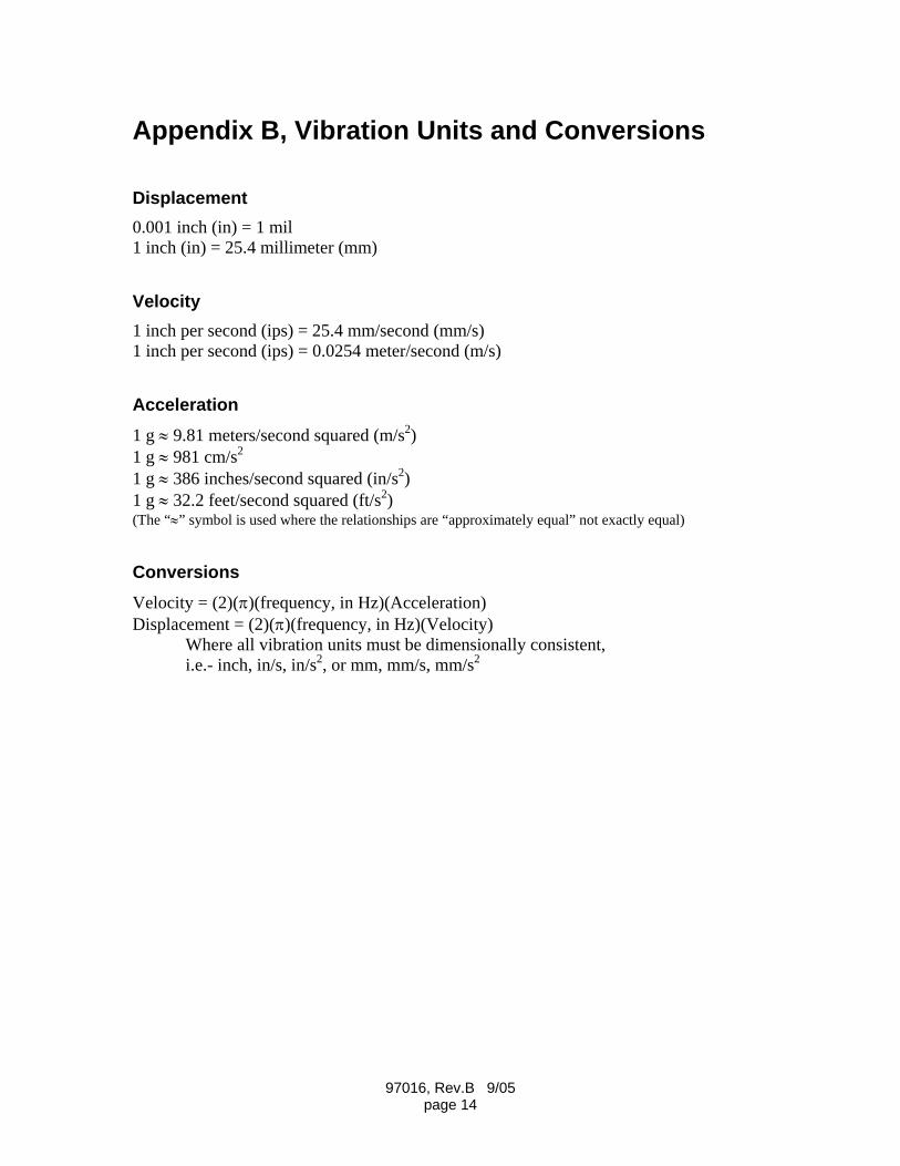
Appendix B, Vibration Units and Conversions
Displacement 0.001 inch (in) = 1 mil 1 inch (in) = 25.4 millimeter (mm)
Velocity 1 inch per second (ips) = 25.4 mm/second (mm/s) 1 inch per second (ips) = 0.0254 meter/second (m/s)
Acceleration 1 g ≈ 9.81 meters/second squared (m/s2) 1 g ≈ 981 cm/s2 1 g ≈ 386 inches/second squared (in/s2) 1 g ≈ 32.2 feet/second squared (ft/s2) (The “≈” symbol is used where the relationships are “approximately equal” not exactly equal)
Conversions Velocity = (2)(π)(frequency, in Hz)(Acceleration) Displacement = (2)(π)(frequency, in Hz)(Velocity) Where all vibration units must be dimensionally consistent,
i.e.- inch, in/s, in/s2, or mm, mm/s, mm/s2
97016, Rev.B 9/05 page 14