pure50+ general information - powers fasteners … information ... installation table for pure50+...
TRANSCRIPT
AD
HESIV
ES
www.powers.com 1
TECH MAN
UAL – ADHESIVES ©2016 PO
WERS VO
LUME 1 – REV. G
GENERAL INFORMATION
SECTION CONTENTS
General Information ......................1Reference Data (ASD) ....................2Performance Data ..........................3Strength Design (SD) .....................6Installation Instructions (Solid Base Materials) .................18Reference Installation Tables .....19Ordering Information ..................20
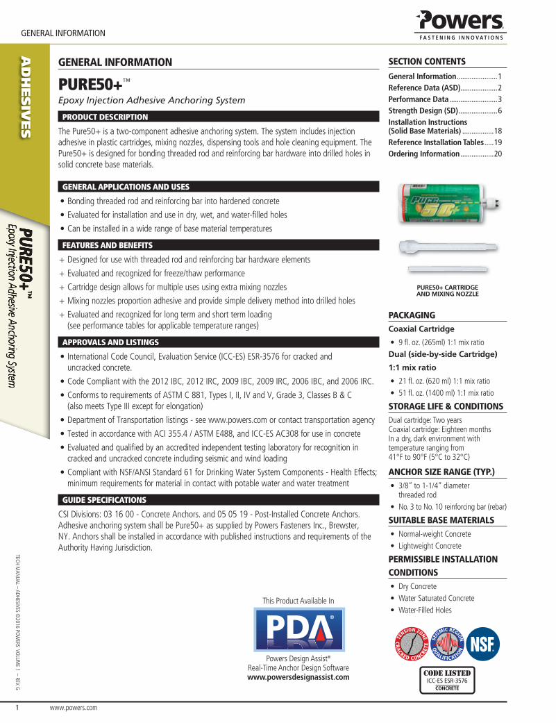
PURE50+ CARTRIDGE AND MIXING NOZZLE
PACKAGINGCoaxial Cartridge
• 9 fl . oz. (265ml) 1:1 mix ratioDual (side-by-side Cartridge)
1:1 mix ratio
• 21 fl . oz. (620 ml) 1:1 mix ratio• 51 fl . oz. (1400 ml) 1:1 mix ratio
STORAGE LIFE & CONDITIONSDual cartridge: Two yearsCoaxial cartridge: Eighteen monthsIn a dry, dark environment with temperature ranging from 41°F to 90°F (5°C to 32°C)
ANCHOR SIZE RANGE (TYP.)• 3/8” to 1-1/4” diameter
threaded rod• No. 3 to No. 10 reinforcing bar (rebar)
SUITABLE BASE MATERIALS• Normal-weight Concrete• Lightweight Concrete
PERMISSIBLE INSTALLATION CONDITIONS• Dry Concrete• Water Saturated Concrete• Water-Filled Holes
TE
NSION ZONE
CR
ACKED CONCRE
TESE
ISMIC REGION
QUALIFICATIO
N
code listedICC-ES ESR-3576
CONCRETE
GENERAL INFORMATION
PURE50+™
Epoxy Injection Adhesive Anchoring System
PRODUCT DESCRIPTION
The Pure50+ is a two-component adhesive anchoring system. The system includes injection adhesive in plastic cartridges, mixing nozzles, dispensing tools and hole cleaning equipment. The Pure50+ is designed for bonding threaded rod and reinforcing bar hardware into drilled holes in solid concrete base materials.
GENERAL APPLICATIONS AND USES
• Bonding threaded rod and reinforcing bar into hardened concrete
• Evaluated for installation and use in dry, wet, and water-fi lled holes
• Can be installed in a wide range of base material temperatures
FEATURES AND BENEFITS
+ Designed for use with threaded rod and reinforcing bar hardware elements
+ Evaluated and recognized for freeze/thaw performance
+ Cartridge design allows for multiple uses using extra mixing nozzles
+ Mixing nozzles proportion adhesive and provide simple delivery method into drilled holes
+ Evaluated and recognized for long term and short term loading(see performance tables for applicable temperature ranges)
APPROVALS AND LISTINGS
• International Code Council, Evaluation Service (ICC-ES) ESR-3576 for cracked and uncracked concrete.
• Code Compliant with the 2012 IBC, 2012 IRC, 2009 IBC, 2009 IRC, 2006 IBC, and 2006 IRC.
• Conforms to requirements of ASTM C 881, Types I, II, IV and V, Grade 3, Classes B & C(also meets Type III except for elongation)
• Department of Transportation listings - see www.powers.com or contact transportation agency
• Tested in accordance with ACI 355.4 / ASTM E488, and ICC-ES AC308 for use in concrete
• Evaluated and qualifi ed by an accredited independent testing laboratory for recognition in cracked and uncracked concrete including seismic and wind loading
• Compliant with NSF/ANSI Standard 61 for Drinking Water System Components - Health Effects; minimum requirements for material in contact with potable water and water treatment
GUIDE SPECIFICATIONS
CSI Divisions: 03 16 00 - Concrete Anchors. and 05 05 19 - Post-Installed Concrete Anchors.Adhesive anchoring system shall be Pure50+ as supplied by Powers Fasteners Inc., Brewster, NY. Anchors shall be installed in accordance with published instructions and requirements of the Authority Having Jurisdiction.
This Product Available In
®
Powers Design Assist®
Real-Time Anchor Design Softwarewww.powersdesignassist.com
www.powers.com 2
AD
HESIV
ES
REFERENCE DATA (ASD)
TECH
MAN
UAL
– AD
HESI
VES
©20
16 P
OW
ERS
VO
LUM
E 1
– R
EV. G
REFERENCE DATA (ASD)
Installation Table for Pure50+ (Solid Concrete Base Materials)Dimension/Property Notation Units Nominal Anchor Size
Threaded Rod - - 3/8 1/2 - 5/8 3/4 7/8 1 - 1-1/4 -
Reinforcing Bar - - #3 - #4 #5 #6 #7 #8 #9 - #10
Nominal anchor diameter d in.(mm)
0.375(9.5)
0.500(12.7)
0.625(15.9)
0.750(19.1)
0.875(22.5)
1.000(25.4)
1.125(28.6)
1.250(31.8)
1.250(31.8)
Carbide drill bit nominal size dbit in. 7/16ANSI
9/16ANSI
5/8ANSI
11/16 or 3/4
ANSI
7/8ANSI
1ANSI
1-1/8ANSI
1-3/8ANSI
1-3/8ANSI
1-1/2ANSI
Minimum embedment hnom in.
(mm)2-3/8(61)
2-3/4(70)
3-1/8(80)
3-1/2(89)
3-1/2(89)
4(102)
4-1/2(114)
5(127)
5(127)
Minimum spacing distance smin in.
(mm)1-7/8(48)
2-1/2(62)
3-1/8(80)
3-3/4(95)
4-3/8(111)
5(127)
5-5/8(143)
6-1/4(159)
6-1/4(159
Minimum edge distance cmin in.
(mm)1-7/8(48)
2-1/2(62)
3-1/8(80)
3-3/4(95)
4-3/8(111)
5(127)
5-5/8(143)
6-1/4(159)
6-1/4(159
Maximum torque1
Tmax
ft.-lb.(N-m)
15(20)
30(41)
60(81)
105(142)
125(169)
165(223)
200(270)
280(379)
280(379)
Maximum torque(low strength rods)1,2
ft.-lb.(N-m)
5(7)
20(27)
40(54)
60(81)
100(136)
165(223) - 280
(379) -
1. Torque may not be applied to the anchors until the full cure time of the adhesive has been achieved.2. These torque values apply to ASTM A 36 / F 1554, Grade 36 carbon steel threaded rods; ASTM F1554 Grade 55 carbon steel threaded rods; and ASTM A193 Grade B8/B8M (Class 1)
stainless steel threaded rods.
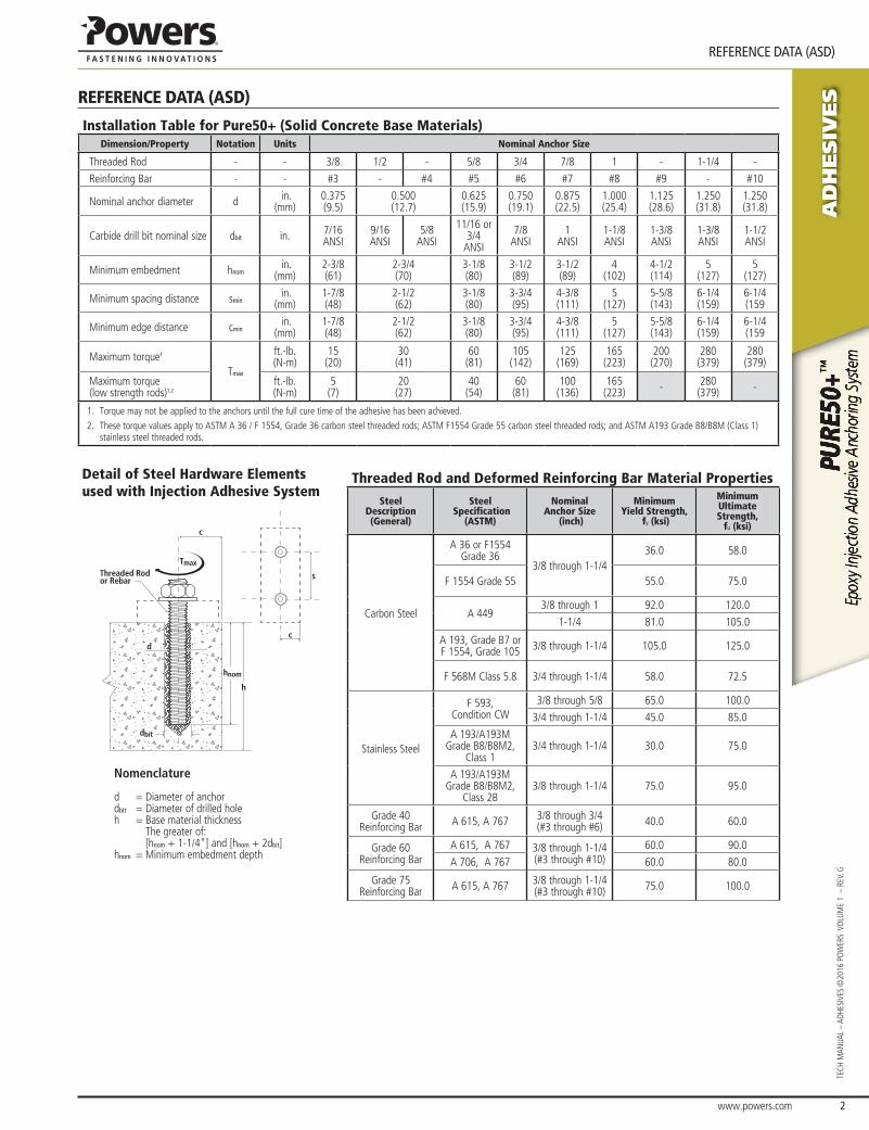
Detail of Steel Hardware Elements used with Injection Adhesive System
Threaded Rod and Deformed Reinforcing Bar Material PropertiesSteel
Description (General)
Steel Specification
(ASTM)
Nominal Anchor Size
(inch)
Minimum Yield Strength,
fy (ksi)
Minimum Ultimate Strength,
fu (ksi)
Carbon Steel
A 36 or F1554 Grade 36
3/8 through 1-1/4 36.0 58.0
F 1554 Grade 55 55.0 75.0
A 4493/8 through 1 92.0 120.0
1-1/4 81.0 105.0
A 193, Grade B7 or F 1554, Grade 105 3/8 through 1-1/4 105.0 125.0
F 568M Class 5.8 3/4 through 1-1/4 58.0 72.5
Stainless Steel
F 593,Condition CW
3/8 through 5/8 65.0 100.0
3/4 through 1-1/4 45.0 85.0
A 193/A193M Grade B8/B8M2,
Class 13/4 through 1-1/4 30.0 75.0
A 193/A193M Grade B8/B8M2,
Class 2B3/8 through 1-1/4 75.0 95.0
Grade 40Reinforcing Bar A 615, A 767 3/8 through 3/4
(#3 through #6) 40.0 60.0
Grade 60Reinforcing Bar
A 615, A 767 3/8 through 1-1/4(#3 through #10)
60.0 90.0
A 706, A 767 60.0 80.0
Grade 75Reinforcing Bar A 615, A 767 3/8 through 1-1/4
(#3 through #10) 75.0 100.0
Tmax
hnom
h
c
c
s
d
dbit
Threaded Rodor Rebar
Nomenclature
d = Diameter of anchordbit = Diameter of drilled holeh = Base material thickness
The greater of:[hnom + 1-1/4"] and [hnom + 2dbit]
hnom = Minimum embedment depth
AD
HESIV
ES
www.powers.com 3
TECH MAN
UAL – ADHESIVES ©2016 PO
WERS VO
LUME 1 – REV. G
PERFORMANCE DATA
PERFORMANCE DATA
Ultimate and Allowable Load Capacities for Pure50+ Installed with Threaded Rod into Normal-Weight Concrete (based on bond strength/concrete capacity)1,2,3,4,5,6,7
Rod Diameter
din.
Drill Diameter
dbit
in.
Minimum Embedment
Depthhef
in.
Minimum Concrete Compressive Strength
3,000 psi 4,000 psi
Ultimate Tension Load Capacity
(lbs.)
Allowable Tension Load Capacity
(lbs.)
Ultimate Tension Load Capacity
(lbs.)
Allowable Tension Load Capacity
(lbs.)
3/8 7/16 3-3/8 9,725 2,430 9,725 2,430
1/2 9/16 4-1/2 15,240 3,810 17,745 4,435
5/8 11/16 or 3/4 5-5/8 22,870 5,720 28,200 7,050
3/4 7/8 6-3/4 31,765 7,940 36,470 9,120
7/8 1 7-7/8 39,615 9,905 45,745 11,435
1 1-1/89 48,750 12,185 66,950 16,740
10 56,665 14,165 69,305 17,325
1-1/4 1-3/8 11-1/4 76,985 19,245 88,895 22,225
1. Allowable load capacities listed are calculated using an applied safety factor of 4.0. Consideration of safety factors of 10 or higher may be necessary depending on the application, such as life safety or overhead.
2. Linear interpolation may be used to determine allowable loads for intermediate embedments and compressive strengths.3. The tabulated load values are applicable to single anchors installed at critical edge and spacing distances and where the minimum member thickness is greater of [hnom + 1-1/4"]
and [hnom + 2dbit].4. The tabulated load values are for applicable for dry concrete. Holes must be drilled with a hammer drill and an ANSI carbide drill bit. Installations in water saturated (wet) concrete or in
water-filled holes (flooded) require a 15% reduction in capacity. Contact Powers Fasteners for more information concerning these installation conditions.5. Adhesives experience reductions in capacity at elevated temperatures. See the in-service temperature chart for allowable load capacity reduction factors.6. Allowable bond strength/concrete capacity must be checked against allowable steel strength in tension to determine the controlling allowable load.7. Allowable shear capacity is controlled by allowable steel strength for the given conditions.
Ultimate and Allowable Load Capacities for Pure50+ Installed with Reinforcing Bar into Normal-Weight Concrete (based on bond strength/concrete capacity)1,2,3,4,5,6,7
Bar Diameter
din.
Drill Diameter
dbit
in.
Minimum Embedment
Depthhef
in.
Minimum Concrete Compressive Strength
3,000 psi 4,000 psi
Ultimate Tension Load Capacity
(lbs.)
Allowable Tension Load Capacity
(lbs.)
Ultimate Tension Load Capacity
(lbs.)
Allowable Tension Load Capacity
(lbs.)
#3 7/16 3-3/8 9,950 2,490 9,950 2,490
#4 9/16 4-1/2 16,340 4,085 18,045 4,510
#511/16
or 3/4
4 16,405 4,100 16,670 4,170
5-5/8 22,955 5,740 25,345 6,335
#6 7/8 6-3/4 29,690 7,425 35,930 8,985
#8 1-1/8 9 48,465 12,115 65,270 16,320
1. Allowable load capacities listed are calculated using an applied safety factor of 4.0. Consideration of safety factors of 10 or higher may be necessary depending on the application, such as life safety or overhead.
2. Linear interpolation may be used to determine allowable loads for intermediate embedments and compressive strengths..3. The tabulated load values are applicable to single anchors installed at critical edge and spacing distances and where the minimum member thickness is greater of [hnom + 1-1/4"]
and [hnom + 2dbit]4. The tabulated load values are for applicable for dry concrete. Holes must be drilled with a hammer drill and an ANSI carbide drill bit. Installations in water saturated (wet) concrete or in
water-filled holes (flooded) require a 15% reduction in capacity. Contact Powers Fasteners for more information concerning these installation conditions.5. Adhesives experience reductions in capacity at elevated temperatures. See the in-service temperature chart for allowable load capacity reduction factors.6. Allowable bond strength/concrete capacity must be checked against allowable steel strength in tension to determine the controlling allowable load.7. Allowable shear capacity is controlled by allowable steel strength for the given conditions.
www.powers.com 4
AD
HESIV
ES
PERFORMANCE DATA
TECH
MAN
UAL
– AD
HESI
VES
©20
16 P
OW
ERS
VO
LUM
E 1
– R
EV. G
Ultimate Load Capacities for Pure50+ Installed with Threaded Rod into Normal-Weight Concrete, with 1-3/4" Edge Distance (Based on Bond Strength/Concrete Capacity)1,2,3,4
Nominal Anchor
Diameter(in.)
Minimum Embedment
Depth(in.)
Minimum Concrete Compressive Strength - f’c (psi)
2,500 psi 3,000 psi 4,000 psi
Ultimate Tension Load Capacity
(lbs.)
Ultimate Shear Load Capacity
(lbs.)
Ultimate Tension Load Capacity
(lbs.)
Ultimate Shear Load Capacity
(lbs.)
Ultimate Tension Load Capacity
(lbs.)
Ultimate Shear Load Capacity
(lbs.)
3/8 3-3/8 6,460 7,200 6,700 7,200 7,100 7,200
1/2 4-1/2 9,625 9,925 9,980 9,925 10,570 9,925
5/8 5-5/8 11,610 12,785 12,040 12,785 12,750 12,785
3/4 6-3/4 12,390 10,360 12,850 10,360 13,615 10,360
1 9 12,390 - 12,850 - 13,615 -
1. The values listed above are ultimate load capacities which should be reduced by a minimum safety factor of 4.0 or greater to determine the allowable working load. Consideration of safety factors of 10 or higher may be necessary depending on the application, such as life safety.
2. Allowable bond strength/concrete capacity must be checked against allowable steel strength to determine the controlling allowable load. 3. The tabulated data is applicable to single anchors at critical edge distance in uncracked concrete, normal-weight concrete having a compressive strength as listed. Values are for dry
concrete in holes drilled with a hammer drill and an ANSI carbide drill bit. 4. Linear interpolation may be used to determine ultimate loads for intermediate compressive strengths.
Allowable Load Capacities for Pure50+ Installed with Threaded Rod into Normal-Weight Concrete with 1-3/4" Edge Distance (Based on Bond Strength / Concrete Capacity)1,2,3,4,5,6
Nominal Anchor
Diameter(in.)
Minimum Embedment
Depth(in.)
Minimum Concrete Compressive Strength - f’c (psi)
2,500 psi 3,000 psi 4,000 psi
Allowable Tension Load Capacity
(lbs.)
Allowable Shear Load Capacity
(lbs.)
Allowable Tension Load Capacity
(lbs.)
Allowable Shear Load Capacity
(lbs.)
Allowable Tension Load Capacity
(lbs.)
Allowable Shear Load Capacity
(lbs.)
3/8 3-3/8 1,615 1,800 1,675 1,800 1,775 1,800
1/2 4 1/2 2,405 2,480 2,495 2,480 2,645 2,480
5/8 5-5/8 2,900 3,195 3,010 3,195 3,190 3,195
3/4 6-3/4 3,100 2,590 3,215 2,590 3,405 2,590
1 9 3,100 - 3,215 - 3,405 -
1. Allowable load capacities listed are calculated using an applied safety factor of 4.0. Consideration of safety factors of 10 or higher may be necessary depending on the application, such as life safety or overhead.
2. Linear interpolation may be used to determine allowable loads for intermediate embedments and compressive strengths..3. The tabulated load values are applicable to single anchors where the minimum member thickness is greater of [hnom + 1-1/4"] and [hnom + 2dbit]4. The tabulated load values are for applicable for dry concrete. Holes must be drilled with a hammer drill and an ANSI carbide drill bit. Installations in wet concrete or in water-filled holes may
require a reduction in capacity. Contact Powers Fasteners for more information concerning these installation conditions.5. Adhesives experience reductions in capacity at elevated temperatures. See the in-service temperature chart for allowable load capacity reduction factors.6. Allowable bond strength/concrete capacity must be checked against allowable steel strength in tension to determine the controlling allowable load.
AD
HESIV
ES
www.powers.com 5
TECH MAN
UAL – ADHESIVES ©2016 PO
WERS VO
LUME 1 – REV. G
PERFORMANCE DATA
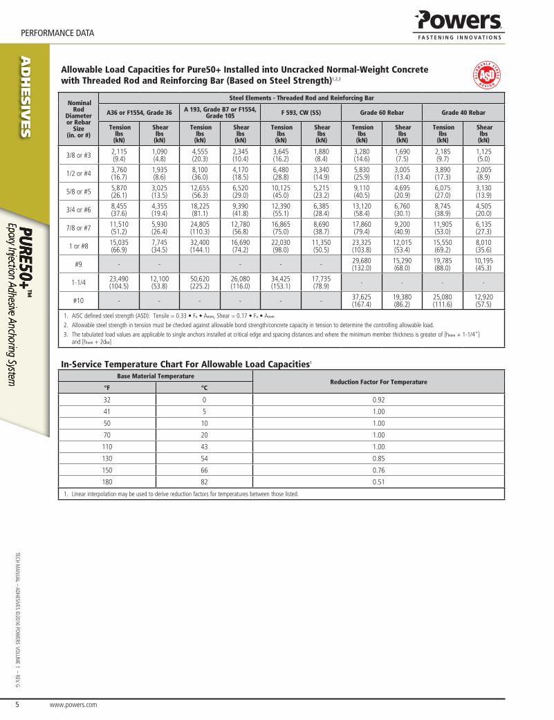
Allowable Load Capacities for Pure50+ Installed into Uncracked Normal-Weight Concrete with Threaded Rod and Reinforcing Bar (Based on Steel Strength)1,2,3
Nominal Rod
Diameter or Rebar
Size(in. or #)
Steel Elements - Threaded Rod and Reinforcing Bar
A36 or F1554, Grade 36 A 193, Grade B7 or F1554, Grade 105 F 593, CW (SS) Grade 60 Rebar Grade 40 Rebar
Tensionlbs
(kN)
Shearlbs
(kN)
Tensionlbs
(kN)
Shearlbs
(kN)
Tensionlbs
(kN)
Shearlbs
(kN)
Tensionlbs
(kN)
Shearlbs
(kN)
Tensionlbs
(kN)
Shearlbs
(kN)
3/8 or #3 2,115(9.4)
1,090(4.8)
4,555(20.3)
2,345(10.4)
3,645(16.2)
1,880(8.4)
3,280(14.6)
1,690(7.5)
2,185(9.7)
1,125(5.0)
1/2 or #4 3,760(16.7)
1,935(8.6)
8,100(36.0)
4,170(18.5)
6,480(28.8)
3,340(14.9)
5,830(25.9)
3,005(13.4)
3,890(17.3)
2,005(8.9)
5/8 or #5 5,870(26.1)
3,025(13.5)
12,655(56.3)
6,520(29.0)
10,125(45.0)
5,215(23.2)
9,110(40.5)
4,695(20.9)
6,075(27.0)
3,130(13.9)
3/4 or #6 8,455(37.6)
4,355(19.4)
18,225(81.1)
9,390(41.8)
12,390(55.1)
6,385(28.4)
13,120(58.4)
6,760(30.1)
8,745(38.9)
4,505(20.0)
7/8 or #7 11,510(51.2)
5,930(26.4)
24,805(110.3)
12,780(56.8)
16,865(75.0)
8,690(38.7)
17,860(79.4)
9,200(40.9)
11,905(53.0)
6,135(27.3)
1 or #8 15,035(66.9)
7,745(34.5)
32,400(144.1)
16,690(74.2)
22,030(98.0)
11,350(50.5)
23,325(103.8)
12,015(53.4)
15,550(69.2)
8,010(35.6)
#9 - - - - - 29,680(132.0)
15,290(68.0)
19,785(88.0)
10,195(45.3)
1-1/4 23,490(104.5)
12,100(53.8)
50,620(225.2)
26,080(116.0)
34,425(153.1)
17,735(78.9) - - - -
#10 - - - - - - 37,625(167.4)
19,380(86.2)
25,080(111.6)
12,920(57.5)
1. AISC defined steel strength (ASD): Tensile = 0.33 • Fu • Anom, Shear = 0.17 • Fu • Anom
2. Allowable steel strength in tension must be checked against allowable bond strength/concrete capacity in tension to determine the controlling allowable load.3. The tabulated load values are applicable to single anchors installed at critical edge and spacing distances and where the minimum member thickness is greater of [hnom + 1-1/4"]
and [hnom + 2dbit]
In-Service Temperature Chart For Allowable Load Capacities1
Base Material TemperatureReduction Factor For Temperature
°F °C
32 0 0.92
41 5 1.00
50 10 1.00
70 20 1.00
110 43 1.00
130 54 0.85
150 66 0.76
180 82 0.51
1. Linear interpolation may be used to derive reduction factors for temperatures between those listed.
www.powers.com 6
AD
HESIV
ES
STRENGTH DESIGN (SD)
TECH
MAN
UAL
– AD
HESI
VES
©20
16 P
OW
ERS
VO
LUM
E 1
– R
EV. G
STRENGTH DESIGN (SD)
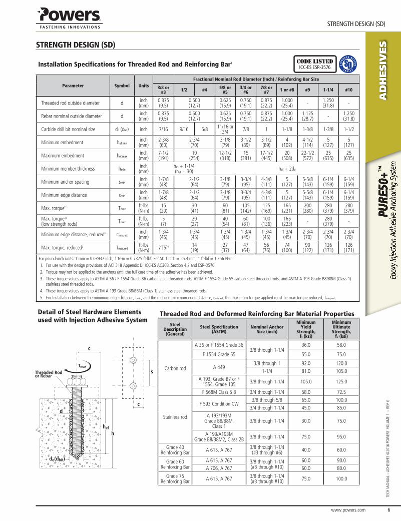
Installation Specifications for Threaded Rod and Reinforcing Bar1 code listedICC-ES ESR-3576
Parameter Symbol UnitsFractional Nominal Rod Diameter (Inch) / Reinforcing Bar Size
3/8 or #3 1/2 #4 5/8 or
#53/4 or
#67/8 or
#7 1 or #8 #9 1-1/4 #10
Threaded rod outside diameter d inch(mm)
0.375(9.5)
0.500(12.7)
0.625(15.9)
0.750(19.1)
0.875(22.2)
1.000(25.4) - 1.250
(31.8) -
Rebar nominal outside diameter d inch(mm)
0.375(9.5)
0.500(12.7)
0.625(15.9)
0.750(19.1)
0.875(22.2)
1.000(25.4)
1.125(28.7) - 1.250
(31.8)
Carbide drill bit nominal size do (dbit) inch 7/16 9/16 5/8 11/16 or 3/4 7/8 1 1-1/8 1-3/8 1-3/8 1-1/2
Minimum embedment hef,mininch(mm)
2-3/8(60)
2-3/4(70)
3-1/8(79)
3-1/2(89)
3-1/2(89)
4(102)
4-1/2(114)
5(127)
5(127)
Maximum embedment hef,maxinch(mm)
7-1/2(191)
10(254)
12-1/2(318)
15(381)
17-1/2(445)
20(508)
22-1/2(572)
25(635)
25(635)
Minimum member thickness hmininch(mm)
hef + 1-1/4(hef + 30) hef + 2do
Minimum anchor spacing smininch(mm)
1-7/8(48)
2-1/2(64)
3-1/8(79)
3-3/4(95)
4-3/8(111)
5(127)
5-5/8(143)
6-1/4(159)
6-1/4(159)
Minimum edge distance cmininch(mm)
1-7/8(48)
2-1/2(64)
3-1/8(79)
3-3/4(95)
4-3/8(111)
5(127)
5-5/8(143)
6-1/4(159)
6-1/4(159)
Max. torque2 Tmaxft-lbs(N-m)
15(20)
30(41)
60(81)
105(142)
125(169)
165(221)
200(280)
280(379)
280(379)
Max. torque2,3
(low strength rods) Tmaxft-lbs(N-m)
5(7)
20(27)
40(54)
60(81)
100(136)
165(223) - 280
(379) -
Minimum edge distance, reduced5 cmin,redinch(mm)
1-3/4(45)
1-3/4(45)
1-3/4(45)
1-3/4(45)
1-3/4(45)
1-3/4(45)
2-3/4(70)
2-3/4(70)
2-3/4(70)
Max. torque, reduced2 Tmax,redft-lbs(N-m) 7 [5]4 14
(19)27
(37)47
(64)56
(76)74
(100)90
(122)126
(171)126
(171)
For pound-inch units: 1 mm = 0.03937 inch, 1 N-m = 0.7375 ft-lbf. For SI: 1 inch = 25.4 mm, 1 ft-lbf = 1.356 N-m.1. For use with the design provisions of ACI 318 Appendix D, ICC-ES AC308, Section 4.2 and ESR-35762. Torque may not be applied to the anchors until the full cure time of the adhesive has been achieved.3. These torque values apply to ASTM A 36 / F 1554 Grade 36 carbon steel threaded rods; ASTM F 1554 Grade 55 carbon steel threaded rods; and ASTM A 193 Grade B8/B8M (Class 1)
stainless steel threaded rods.4. These torque values apply to ASTM A 193 Grade B8/B8M (Class 1) stainless steel threaded rods.5. For Installation between the minimum edge distance, cmin, and the reduced minimum edge distance, cmin,red, the maximum torque applied must be max torque reduced, Tmax,red.
Detail of Steel Hardware Elements used with Injection Adhesive System
Threaded Rod and Deformed Reinforcing Bar Material Properties
Steel Description (General)
Steel Specification (ASTM)
Nominal Anchor Size (inch)
Minimum Yield
Strength, fy (ksi)
Minimum Ultimate Strength,
fu (ksi)
Carbon rod
A 36 or F 1554 Grade 363/8 through 1-1/4
36.0 58.0
F 1554 Grade 55 55.0 75.0
A 4493/8 through 1 92.0 120.0
1-1/4 81.0 105.0
A 193, Grade B7 or F 1554, Grade 105 3/8 through 1-1/4 105.0 125.0
F 568M Class 5 8 3/4 through 1-1/4 58.0 72.5
Stainless rod
F 593 Condition CW3/8 through 5/8 65.0 100.0
3/4 through 1-1/4 45.0 85.0
A 193/193MGrade B8/B8M,
Class 13/8 through 1-1/4 30.0 75.0
A 193/A193MGrade B8/B8M2, Class 2B 3/8 through 1-1/4 75.0 95.0
Grade 40 Reinforcing Bar A 615, A 767 3/8 through 1-1/4
(#3 through #6) 40.0 60.0
Grade 60 Reinforcing Bar
A 615, A 767 3/8 through 1-1/4(#3 through #10)
60.0 90.0
A 706, A 767 60.0 80.0
Grade 75 Reinforcing Bar A 615, A 767 3/8 through 1-1/4
(#3 through #10) 75.0 100.0
Tmax
hef
h
c
c
s
d
do(dbit)
Threaded Rodor Rebar

AD
HESIV
ES
www.powers.com 7
TECH MAN
UAL – ADHESIVES ©2016 PO
WERS VO
LUME 1 – REV. G
STRENGTH DESIGN (SD)
Steel Tension and Shear Design for Threaded Rod in Normal Weight Concrete(For use with load combinations taken from ACI318 Section 9.2)
code listedICC-ES ESR-3576
Design Information Symbol UnitsNominal Rod Diameter1 (inch)
3/8 1/2 5/8 3/4 7/8 1 1-1/4
Threaded rod nominal outside diameter d inch(mm)
0.375(9.5)
0.500(12.7)
0.625(15.9)
0.750(19.1)
0.875(22.2)
1.000(25.4)
1.250(31.8)
Threaded rod effective cross-sectional area Aseinch2
(mm2)0.0775
(50)0.1419
(92)0.2260(146)
0.3345(216)
0.4617(298)
0.6057(391)
0.9691(625)
ASTM A 36 and
ASTM F 1554 Grade 36
Nominal strength as governed by steel strength (for a single anchor)
Nsalbf
(kN)4,495(20.0)
8,230(36.6)
13,110(58.3)
19,400(86.3)
26,780(119.1)
35,130(156.3)
56,210(250.0)
Vsalbf
(kN)2,695(12.0)
4,940(22.0)
7,860(35.0)
11,640(51.8)
16,070(71.4)
21,080(93.8)
33,725(150.0)
Reduction factor for seismic shear αV,seis - 0.80 0.80 0.80 0.80 0.80 0.80 0.80Strength reduction factor for tension2 φ - 0.75Strength reduction factor for shear2 φ - 0.65
ASTM F 1554 Grade 55
Nominal strength as governed by steel strength(for a single anchor)
Nsalbf
(kN)5,810(25.9)
10,640(47.3)
16,950(75.4)
25,085(111.6)
34,625(154.0)
45,425(202.0)
72,680(323.3)
Vsalbf
(kN)3,485(15.5)
6,385(28.4)
10,170(45.2)
15,050(67.0)
20,775(92.4)
27,255(121.2)
43,610(194.0)
Reduction factor for seismic shear αV,seis - 0.80 0.80 0.80 0.80 0.80 0.80 0.80Strength reduction factor for tension2 φ - 0.75Strength reduction factor for shear2 φ - 0.65
ASTM A 193Grade B7
and ASTM F 1554
Grade 105
Nominal strength as governed by steel strength (for a single anchor)
Nsalbf
(kN)9,685(43.1)
17,735(78.9)
28,250(125.7)
41,810(186.0)
57,710(256.7)
75,710(336.8)
121,135(538.8)
Vsalbf
(kN)5,815(25.9)
10,640(7.3)
16,950(75.4)
25,085(111.6)
34,625(154.0)
45,425(202.1)
72,680(323.3)
Reduction factor for seismic shear αV,seis - 0.80 0.80 0.80 0.80 0.80 0.80 0.80Strength reduction factor for tension2 φ - 0.75Strength reduction factor for shear2 φ - 0.65
ASTM A 449
Nominal strength asgoverned by steel strength(for a single anchor)
Nsalbf
(kN)9,300(41.4)
17,025(75.7)
27,120(120.6)
40,140(178.5)
55,905(248.7)
72,685(323.3)
101,755(452.6)
Vsalbf
(kN)5,580(24.8)
10,215(45.4)
16,270(72.4)
24,085(107.1)
33,540(149.2)
43,610(194.0)
61,050(271.6)
Reduction factor for seismic shear αV,seis - 0.80 0.80 0.80 0.80 0.80 0.80 0.80Strength reduction factor for tension2 φ - 0.75Strength reduction factor for shear2 φ - 0.65
ASTM F568Class 5.8
(ISO 898-1)
Nominal strength as governed by steel strength (for a single anchor)
Nsalbf
(kN)5,620(25.0)
10,290(45.8)
16,385(72.9)
24,250(107.9)
33,475(148.9)
43,915(195.4) -5
Vsalbf
(kN)3,370(15.0)
6,175(27.5)
9,830(43.7)
14,550(64.7)
20,085(89.3)
26,350(117.2) -5
Reduction factor for seismic shear αV,seis - 0.80 0.80 0.80 0.80 0.80 0.80 -5
Strength reduction factor for tension3 φ - 0.65Strength reduction factor for shear3 φ - 0.60
ASTM F 593CW Stainless(Types 304 and 316)
Nominal strength as governed by steel strength (for a single anchor)
Nsalbf
(kN)7,750(34.5)
14,190(63.1)
22,600(100.5)
28,430(126.5)
39,245(174.6)
51,485(229.0)
82,370(366.4)
Vsalbf
(kN)4,650(20.7)
8,515(37.9)
13,560(60.3)
17,060(75.9)
23,545(104.7)
30,890(137.4)
49,425(219.8)
Reduction factor for seismic shear αV,seis - 0.70 0.70 0.80 0.80 0.80 0.80 0.80Strength reduction factor for tension3 φ - 0.65Strength reduction factor for shear3 φ - 0.60
ASTM A 193Grade B8/B8M,
Class 1 Stainless
(Types 304and 316)
Nominal strength as governed by steel strength (for a single anchor)4
Nsalbf
(kN)4,420(19.7)
8,090(36.0)
12,880(57.3)
19,065(84.8)
26,315(117.1)
34,525(153.6)
55,240(245.7)
Vsalbf
(kN)2,650(11.8)
4,855(21.6)
7,730(34.4)
11,440(50.9)
15,790(70.2)
20,715(92.1)
33,145(147.4)
Reduction factor for seismic shear αV,seis - 0.70 0.70 0.80 0.80 0.80 0.80 0.80Strength reduction factor for tension2 φ - 0.75Strength reduction factor for shear2 φ - 0.65
ASTM A 193Grade B8/
B8M2,Class 2B Stainless
(Types 304 and 316)
Nominal strength as governed by steel strength (for a single anchor)
Nsalbf
(kN)7,365(32.8)
13,480(60.0)
21,470(95.5)
31,775(141.3)
43,860(195.1)
57,545(256.0)
92,065(409.5)
Vsalbf
(kN)4,420(19.7)
8,085(36.0)
12,880(57.3)
19,065(84.8)
26,315(117.1)
34,525(153.6)
55,240(245.7)
Reduction factor for seismic shear αV,seis - 0.70 0.70 0.80 0.80 0.80 0.80 0.80Strength reduction factor for tension2 φ - 0.75Strength reduction factor for shear2 φ - 0.65
For SI: 1 inch = 25.4 mm, 1 lbf = 4.448 N. For pound-inch units: 1 mm = 0.03937 inches, 1 N = 0.2248 lbf.1. Values provided for steel element material types are based on minimum specified strengths and calculated in accordance with ACI 318-11 Eq. (D-2) and Eq. (D-29) except where noted.
Nuts and washers must be appropriate for the rod. Nuts must have specified proof load stresses equal to or greater than the minimum tensile strength of the specified threaded rod.2. The tabulated value of φ applies when the load combinations of Section 1605.2 of the IBC or ACI 318 Section 9.2 are used in accordance with ACI 318 D.4.3. If the load combinations of
ACI 318 Appendix C are used, the appropriate value of φ must be determined in accordance with ACI 318 D.4.4. Values correspond to ductile steel elements.3. The tabulated value of φ applies when the load combinations of Section 1605.2 of the IBC or ACI 318 Section 9.2 are used in accordance with ACI 318-11 D.4.3. If the load combinations
of ACI 318 Appendix C are used, the appropriate value of φ must be determined in accordance with ACI 318 D.4.4. Values correspond to brittle steel elements4. In accordance with ACI 318 D.5.1.2 and D.6.1.2 the calculated values for nominal tension and shear strength for ASTM A193 Grade B8/B8M Class 1 stainless steel threaded rods are
based on limiting the specified tensile strength of the anchor steel to 1.9fy or 57,000 psi (393 MPa).5. The referenced standard includes rod diameters up to and including 1-inch (24 mm).

www.powers.com 8
AD
HESIV
ES
STRENGTH DESIGN (SD)
TECH
MAN
UAL
– AD
HESI
VES
©20
16 P
OW
ERS
VO
LUM
E 1
– R
EV. G
Steel Tension and Shear Design for Reinforcing Bars in Normal Weight Concrete(For use with load combinations taken from ACI318 Section 9.2)
code listedICC-ES ESR-3576
Design Information Symbol UnitsNominal Reinforcing Bar Size (Rebar)1
No. 3 No. 4 No. 5 No. 6 No. 7 No. 8 No. 9 No. 10
Rebar nominal outside diameter d inch(mm)
0.375(9.5)
0.500(12.7)
0.625(15.9)
0.750(19.1)
0.875(22.2)
1.000(25.4)
1.125(28.7)
1.250(32.3)
Rebar effective cross-sectional area Aseinch2
(mm2)0.110(71.0)
0.200(129.0)
0.310(200.0)
0.440(283.9)
0.600(387.1)
0.790(509.7)
1.000(645.2)
1.270(819.4)
ASTMA 615
Grade 75
Nominal strength as governed by steel strength (for a single anchor)
Nsalbf
(kN)11,000(48.9)
20,000(89.0)
31,000(137.9)
44,000(195.7)
60,000(266.9)
79,000(351.4)
100,000(444.8)
127,000(564.9)
Vsalbf
(kN)6,600(29.4)
12,000(53.4)
18,600(82.7)
26,400(117.4)
36,000(160.1)
47,400(210.8)
60,000(266.9)
76,200(338.9)
Reduction factor for seismic shear αV,seis - 0.70 0.70 0.80 0.80 0.80 0.80 0.80 0.80
Strength reduction factor for tension3 φ - 0.65
Strength reduction factor for shear3 φ - 0.60
ASTMA 615
Grade 60
Nominal strength as governed by steel strength (for a single anchor)
Nsalbf
(kN)9,900(44.0)
18,000(80.1)
27,900(124.1)
39,600(176.1)
54,000(240.2)
71,100(316.3)
90,000(400.3)
114,300(508.4)
Vsalbf
(kN)5,940(26.4)
10,800(48.0)
16,740(74.5)
23,760(105.7)
32,400(144.1)
42,660(189.8)
54,000(240.2)
68,580(305.0)
Reduction factor for seismic shear αV,seis - 0.70 0.70 0.80 0.80 0.80 0.80 0.80 0.80
Strength reduction factor for tension2 φ - 0.75
Strength reduction factor for shear2 φ - 0.65
ASTM A 706 Grade 60
Nominal strength as governed by steel strength (for a single anchor)
Nsalbf
(kN)8,800(39.1)
16,000(71.2)
24,800(110.3)
35,200(156.6)
48,000(213.5)
63,200(281.1)
80,000(355.9)
101,600(452.0)
Vsalbf
(kN)5,280(23.5)
9,600(42.7)
14,880(66.2)
21,120(94.0)
28,800(128.1)
37,920(168.7)
48,000(213.5)
60,960(271.2)
Reduction factor for seismic shear αV,seis - 0.70 0.70 0.80 0.80 0.80 0.80 0.80 0.80
Strength reduction factor for tension2 φ - 0.75
Strength reduction factor for shear2 φ - 0.65
ASTM A 615 Grade 40
Nominal strength as governed by steel strength (for a single anchor)
Nsalbf
(kN)6,600(29.4)
12,000(53.4)
18,600(82.7)
26,400(117.4) In accordance with ASTM A 615,
Grade 40 bars are furnished only in sizes No. 3 through No. 6Vsa
lbf(kN)
3,960(17.6)
7,200(32.0)
11,160(49.6)
15,840(70.5)
Reduction factor for seismic shear αV,seis - 0.70 0.70 0.80 0.80
Strength reduction factor for tension2 φ - 0.75
Strength reduction factor for shear2 φ - 0.65
For SI: 1 inch = 25.4 mm, 1 lbf = 4.448 N. For pound-inch units: 1 mm = 0.03937 inches, 1 N = 0.2248 lbf.1. Values provided for reinforcing bar material types based on minimum specified strengths and calculated in accordance with ACI 318-11 Eq. (D-2) and Eq. (D-29).2. The tabulated value of φ applies when the load combinations of Section 1605.2 of the IBC or ACI 318 Section 9.2 are used in accordance with ACI 318 D.4.3. If the load combinations of
ACI 318 Appendix C are used, the appropriate value of φ must be determined in accordance with ACI 318 D.4.4. Values correspond to ductile steel elements.3. The tabulated value of φ applies when the load combinations of Section 1605.2 of the IBC or ACI 318 Section 9.2 are used in accordance with ACI 318 D.4.3. If the load combinations of
ACI 318 Appendix C are used, the appropriate value of φ must be determined in accordance with ACI 318 D.4.4. Values correspond to brittle steel elements.

AD
HESIV
ES
www.powers.com 9
TECH MAN
UAL – ADHESIVES ©2016 PO
WERS VO
LUME 1 – REV. G
STRENGTH DESIGN (SD)
Concrete Breakout Design Information for Threaded Rod and Reinforcing Bars (For use with loads combinations taken from ACI 318 Section 9.2)1
code listedICC-ES ESR-3576
Design Information Symbol UnitsNominal Rod Diameter (inch) / Reinforcing Bar Size
3/8 or #3 1/2 or #4 5/8 or #5 3/4 or #6 7/8 or #7 1 or #8 #9 1-1/4 or #10
Effectiveness factor forcracked concrete kc,cr
-(SI)
17(7.1)
Effectiveness factor foruncracked concrete kc,uncr
-(SI)
24(10.0)
Minimum embedment hef,mininch(mm)
2-3/8(60)
2-3/4(70)
3-1/8(79)
3-1/2(89)
3-1/2(89)
4(102)
4-1/2(114)
5(127)
Maximum embedment hef,maxinch(mm)
7-1/2(191)
10(254)
12-1/2(318)
15(381)
17-1/2(445)
20(508)
22-1/2(572)
25(635)
Minimum anchor spacing smininch(mm)
1-7/8(48)
2-1/2(64)
3-1/8(79)
3-3/4(95)
4-3/8(111)
5(127)
5-5/8(143)
6-1/4(159)
Minimum edge distance2 cmininch(mm) 5d where d is nominal outside diameter of the anchor
Minimum edge distance, reduced2 cmin,redinch(mm)
1-3/4(45)
1-3/4(45)
1-3/4(45)
1-3/4(45)
1-3/4(45)
1-3/4(45)
2-3/4(70)
2-3/4(70)
Minimum member thickness hmininch(mm)
hef + 1-1/4(hef + 30) hef + 2do where do is hole diameter;
Critical edge distance—splitting (for uncracked concrete only)3 cac
inch cac = hef ∙ (τuncr
1160)0.4 ∙ [3.1-0.7 hhef
]
(mm) cac = hef ∙ (τuncr
8 )0.4 ∙ [3.1-0.7 hhef
]
Strength reduction factor for tension, concrete failure modes, Condition B4 φ - 0.65
Strength reduction factor for shear, concrete failure modes, Condition B4 φ - 0.70
For SI: 1 inch = 25.4 mm, 1 lbf = 4.448 N. For pound-inch units: 1 mm = 0.03937 inch, 1 N = 0.2248 lbf.1. Additional setting information is described in the installation instructions.2. For installation between the minimum edge distance, cmin, and the reduced minimum edge distance, cmin,red, the maximum torque applied must be reduced (multiplied) by a factor of 0.45.3. τk,uncr need not be taken as greater than: τk,uncr = √ hef • f'ckuncr •
π • d
and hhef
need not be taken as larger than 2.4.
4. Condition A requires supplemental reinforcement, while Condition B applies where supplemental reinforcement is not provided or where pryout governs, as set forth in ACI 318 D.4.3. The tabulated value of φ applies when the load combinations of Section 1605.2 of the IBC or ACI 318 Section 9.2 are used in accordance with ACI 318 D.4.4. If the load combinations of ACI 318 Appendix C are used, the appropriate value of φ must be determined in accordance with ACI 318 D.4.4.
www.powers.com 10
AD
HESIV
ES
STRENGTH DESIGN (SD)
TECH
MAN
UAL
– AD
HESI
VES
©20
16 P
OW
ERS
VO
LUM
E 1
– R
EV. G
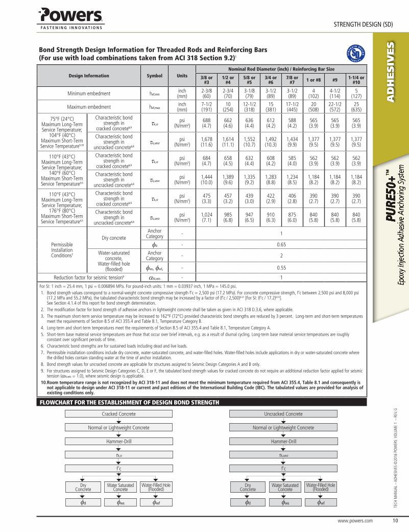
Bond Strength Design Information for Threaded Rods and Reinforcing Bars (For use with load combinations taken from ACI 318 Section 9.2)1
Design Information Symbol UnitsNominal Rod Diameter (inch) / Reinforcing Bar Size
3/8 or #3
1/2 or #4
5/8 or #5
3/4 or #6
7/8 or #7 1 or #8 #9 1-1/4 or
#10
Minimum embedment hef,mininch(mm)
2-3/8(60)
2-3/4(70)
3-1/8(79)
3-1/2(89)
3-1/2(89)
4(102)
4-1/2(114)
5(127)
Maximum embedment hef,maxinch(mm)
7-1/2(191)
10(254)
12-1/2(318)
15(381)
17-1/2(445)
20(508)
22-1/2(572)
25(635)
75°F (24°C) Maximum Long-Term Service Temperature;
104°F (40°C) Maximum Short-Term Service Temperature5,10
Characteristic bond strength in
cracked concrete6,9τk,cr
psi(N/mm2)
688(4.7)
662(4.6)
636(4.4)
612(4.2)
588(4.2)
565(3.9)
565(3.9)
565(3.9)
Characteristic bond strength in
uncracked concrete6,8τk,uncr
psi(N/mm2)
1,678(11.6)
1,614(11.1)
1,552(10.7)
1,492(10.3)
1,434(9.9)
1,377(9.5)
1,377(9.5)
1,377(9.5)
110°F (43°C) Maximum Long-Term Service Temperature;
140°F (60°C) Maximum Short-Term Service Temperature3,5
Characteristic bond strength in
cracked concrete6,9τk,cr
psi(N/mm2)
684(4.7)
658(4.5)
632(4.4)
608(4.2)
585(4.0)
562(3.9)
562(3.9)
562(3.9)
Characteristic bond strength in
uncracked concrete6,8τk,uncr
psi(N/mm2)
1,444(10.0)
1,389(9.6)
1,335(9.2)
1,283(8.8)
1,234(8.5)
1,184(8.2)
1,184(8.2)
1,184(8.2)
110°F (43°C) Maximum Long-Term Service Temperature;
176°F (80°C) Maximum Short-Term Service Temperature4,5
Characteristic bond strength in
cracked concrete6,9τk,cr
psi(N/mm2)
475(3.3)
457(3.2)
439(3.0)
422(2.9)
406(2.8)
390(2.7)
390(2.7)
390(2.7)
Characteristic bond strength in
uncracked concrete6,8τk,uncr
psi(N/mm2)
1,024(7.1)
985(6.8)
947(6.5)
910(6.3)
875(6.0)
840(5.8)
840(5.8)
840(5.8)
Permissible Installation Conditions7
Dry concreteAnchor
Category - 1
φd - 0.65
Water-saturated concrete,
Water-filled hole (flooded)
Anchor Category - 2
φws, φwf, - 0.55
Reduction factor for seismic tension9 αN,seis - 1
For SI: 1 inch = 25.4 mm, 1 psi = 0.006894 MPa. For pound-inch units: 1 mm = 0.03937 inch, 1 MPa = 145.0 psi.1. Bond strength values correspond to a normal-weight concrete compressive strength f'c = 2,500 psi (17.2 MPa). For concrete compressive strength, f'c between 2,500 psi and 8,000 psi
(17.2 MPa and 55.2 MPa), the tabulated characteristic bond strength may be increased by a factor of (f'c / 2,500)0.23 [For SI: (f'c / 17.2)0.23]. See Section 4.1.4 of this report for bond strength determination.
2. The modification factor for bond strength of adhesive anchors in lightweight concrete shall be taken as given in ACI 318 D.3.6, where applicable.3. The maximum short-term service temperature may be increased to 162°F (72°C) provided characteristic bond strengths are reduced by 3 percent. Long-term and short-term temperatures
meet the requirements of Section 8.5 of ACI 355.4 and Table 8.1, Temperature Category B.4. Long-term and short-term temperatures meet the requirements of Section 8.5 of ACI 355.4 and Table 8.1, Temperature Category A.5. Short-term base material service temperatures are those that occur over brief intervals, e.g. as a result of diurnal cycling. Long-term base material service temperatures are roughly
constant over significant periods of time.6. Characteristic bond strengths are for sustained loads including dead and live loads.7. Permissible installation conditions include dry concrete, water-saturated concrete, and water-filled holes. Water-filled holes include applications in dry or water-saturated concrete where
the drilled holes contain standing water at the time of anchor installation. 8. Bond strength values for uncracked concrete are applicable for structures assigned to Seismic Design Categories A and B only.9. For structures assigned to Seismic Design Categories C, D, E or F, the tabulated bond strength values for cracked concrete do not require an additional reduction factor applied for seismic
tension (αN,seis = 1.0), where seismic design is applicable.10. Room temperature range is not recognized by ACI 318-11 and does not meet the minimum temperature required from ACI 355.4, Table 8.1 and consequently is
not applicable to design under ACI 318-11 or current and past editions of the International Building Code (IBC). The tabulated values are provided for analysis of existing conditions only.
FLOWCHART FOR THE ESTABLISHMENT OF DESIGN BOND STRENGTH
Cracked Concrete
Normal or Lightweight Concrete
DryConcrete
Water Saturated Concrete
Water-Filled Hole(Flooded)
φd φws φwf
Hammer-Drill
τk,cr
f’c
Uncracked Concrete
Normal or Lightweight Concrete
DryConcrete
Water Saturated Concrete
Water-Filled Hole(Flooded)
φd φws φwf
Hammer-Drill
τk,uncr
f’c

AD
HESIV
ES
www.powers.com 11
TECH MAN
UAL – ADHESIVES ©2016 PO
WERS VO
LUME 1 – REV. G
STRENGTH DESIGN (SD)
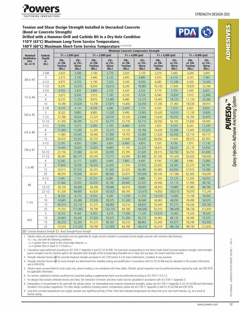
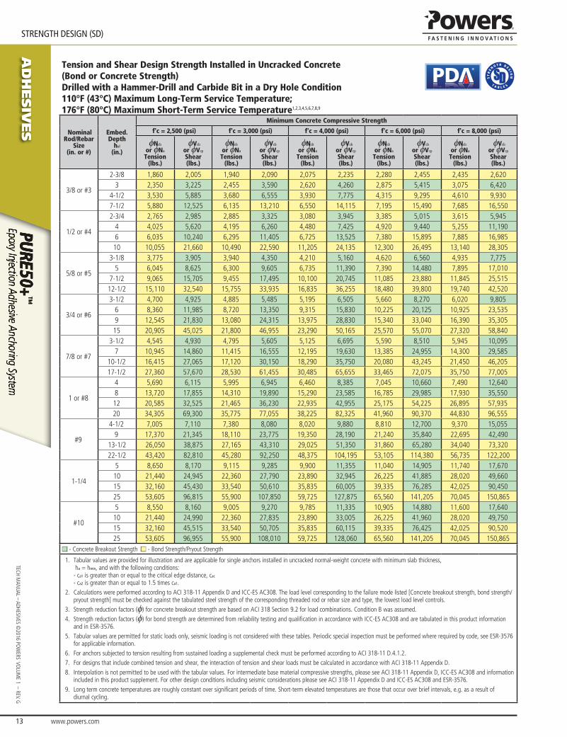
Tension and Shear Design Strength Installed in Uncracked Concrete(Bond or Concrete Strength)Drilled with a Hammer-Drill and Carbide Bit in a Dry Hole Condition75°F (24°C) Maximum Long-Term Service Temperature; 104°F (40°C) Maximum Short-Term Service Temperature1,2,3,4,5,6,7,8
Nominal Rod/Rebar
Size(in. or #)
Embed.Depth
hef
(in.)
Minimum Concrete Compressive Strength
f'c = 2,500 (psi) f'c = 3,000 (psi) f'c = 4,000 (psi) f'c = 6,000 (psi) f'c = 8,000 (psi)
φNcb
or φNa
Tension(lbs.)
φVcb
or φVcp
Shear(lbs.)
φNcb
or φNa
Tension(lbs.)
φVcb
or φVcp
Shear(lbs.)
φNcb
or φNa
Tension(lbs.)
φVcb
or φVcp
Shear(lbs.)
φNcb
or φNa
Tension(lbs.)
φVcb
or φVcp
Shear(lbs.)
φNcb
or φNa
Tension(lbs.)
φVcb
or φVcp
Shear(lbs.)
3/8 or #3
2-3/8 2,855 2,570 3,125 2,920 3,400 3,490 3,730 4,020 3,990 4,2953 3,855 3,930 4,020 4,375 4,295 5,190 4,715 6,595 5,035 7,820
4-1/2 5,780 7,170 6,030 7,990 6,440 9,470 7,070 12,040 7,555 14,2757-1/2 9,635 15,265 10,050 17,005 10,735 20,160 11,785 25,385 12,595 27,125
1/2 or #4
2-3/4 3,555 3,305 3,895 3,755 4,500 4,590 5,510 6,095 5,920 7,2454 6,240 6,700 6,835 7,610 7,345 9,045 8,060 11,500 8,615 13,6356 9,890 12,475 10,310 13,895 11,015 16,475 12,095 20,945 12,920 24,83510 16,480 26,570 17,185 29,600 18,360 35,095 20,155 43,410 21,535 46,380
5/8 or #5
3-1/8 4,310 4,120 4,720 4,680 5,450 5,720 6,675 7,600 7,710 9,2955 8,720 9,985 9,555 11,345 11,030 13,875 12,115 17,645 12,940 20,920
7-1/2 14,855 19,135 15,490 21,320 16,550 25,275 18,170 32,135 19,410 38,10012-1/2 24,760 40,780 25,820 45,430 27,585 53,865 30,285 65,225 32,355 69,685
3/4 or #6
3-1/2 5,105 5,015 5,595 5,700 6,460 6,970 7,910 9,255 9,135 11,3206 11,465 13,595 12,560 15,445 14,500 18,895 16,770 24,525 17,915 29,0809 20,565 26,600 21,445 29,635 22,915 35,135 25,155 44,670 26,875 52,96015 34,275 56,675 35,745 63,135 38,190 74,855 41,920 90,290 44,790 96,470
7/8 or #7
3-1/2 5,105 4,930 5,595 5,605 6,460 6,855 7,910 9,100 9,135 11,1307 14,445 16,605 15,825 18,865 18,275 23,075 21,935 30,405 23,435 36,050
10-1/2 26,540 32,800 28,055 36,740 29,975 43,560 32,905 55,380 35,155 65,66017-1/2 44,840 70,270 46,760 78,280 49,960 92,815 54,840 117,995 58,595 126,200
1 or #8
4 6,240 6,115 6,835 6,945 7,895 8,495 9,665 11,280 11,160 13,8008 17,650 19,750 19,335 22,435 22,325 27,440 27,340 36,450 29,395 43,32512 32,425 39,005 35,190 44,150 37,595 52,350 41,270 66,550 44,090 78,90520 56,240 84,450 58,645 94,075 62,660 111,540 68,780 141,805 73,485 158,280
#9
4-1/2 7,445 7,110 8,155 8,080 9,420 9,880 11,535 13,125 13,320 16,0559 21,060 23,055 23,070 26,190 26,640 32,035 32,625 42,550 37,205 51,780
13-1/2 38,690 45,540 42,380 51,740 47,580 62,575 52,230 79,550 55,805 94,32022-1/2 71,175 100,910 74,225 112,415 79,300 133,285 87,050 169,445 93,005 200,325
1-1/4
5 8,720 8,170 9,555 9,285 11,030 11,355 13,510 15,085 15,600 18,45010 24,665 26,380 27,020 29,975 31,200 36,660 38,210 48,690 44,125 59,55515 45,315 52,110 49,640 59,200 57,320 72,410 64,485 92,960 68,895 110,22025 87,870 117,980 91,635 131,425 97,905 155,825 107,470 198,100 114,825 234,885
#10
5 8,720 8,160 9,555 9,270 11,030 11,335 13,510 15,060 15,600 18,42010 24,665 26,430 27,020 30,025 31,200 36,725 38,210 48,780 44,125 59,66015 45,315 52,205 49,640 59,310 57,320 72,545 64,485 93,135 68,895 110,42525 87,870 118,150 91,635 131,620 97,905 156,055 107,470 198,395 114,825 235,230
■ - Concrete Breakout Strength ■ - Bond Strength/Pryout Strength
1. Tabular values are provided for illustration and are applicable for single anchors installed in uncracked normal-weight concrete with minimum slab thickness, ha = hmin, and with the following conditions: - ca1 is greater than or equal to the critical edge distance, cac
- ca2 is greater than or equal to 1.5 times ca1.2. Calculations were performed according to ACI 318-11 Appendix D and ICC-ES AC308. The load level corresponding to the failure mode listed [Concrete breakout strength, bond strength/
pryout strength] must be checked against the tabulated steel strength of the corresponding threaded rod or rebar size and type, the lowest load level controls. This temperature range is not recognized by ACI 318-11 and does not meet the minimum temperature requirements from ACI 355.4 Table 8.1 and consequently is not applicable to design under ACI 318-11 or current and past editions of the International Building Code (IBC). The Tabulated values are provided for analysis and evaluation of existing conditions only.
3. Strength reduction factors (φ) for concrete breakout strength are based on ACI 318 Section 9.2 for load combinations. Condition B was assumed.4. Strength reduction factors (φ) for bond strength are determined from reliability testing and qualification in accordance with ICC-ES AC308 and are tabulated in this product information
and in ESR-3576. 5. Tabular values are permitted for short-term, static loads only, seismic loading is not considered with these tables.6. For designs that include combined tension and shear, the interaction of tension and shear loads must be calculated in accordance with ACI 318-11 Appendix D.7. Interpolation is not permitted to be used with the tabular values. For intermediate base material compressive strengths, please see ACI 318-11 Appendix D, ICC-ES AC308 and information
included in this product supplement. For other design conditions including seismic considerations please see ACI 318-11 Appendix D and ICC-ES AC308 and ESR-3576.8. Long term concrete temperatures are roughly constant over significant periods of time. Short-term elevated temperatures are those that occur over brief intervals, e.g. as a result of
diurnal cycling.
www.powers.com 12
AD
HESIV
ES
STRENGTH DESIGN (SD)
TECH
MAN
UAL
– AD
HESI
VES
©20
16 P
OW
ERS
VO
LUM
E 1
– R
EV. G
Tension and Shear Design Strength Installed in Uncracked Concrete(Bond or Concrete Strength)Drilled with a Hammer-Drill and Carbide Bit in a Dry Hole Condition110°F (43°C) Maximum Long-Term Service Temperature; 140°F (60°C) Maximum Short-Term Service Temperature1,2,3,4,5,6,7,8,9
®
Nominal Rod/Rebar
Size(in. or #)
Embed.Depth
hef
(in.)
Minimum Concrete Compressive Strength
f'c = 2,500 (psi) f'c = 3,000 (psi) f'c = 4,000 (psi) f'c = 6,000 (psi) f'c = 8,000 (psi)
φNcb
or φNa
Tension(lbs.)
φVcb
or φVcp
Shear(lbs.)
φNcb
or φNa
Tension(lbs.)
φVcb
or φVcp
Shear(lbs.)
φNcb
or φNa
Tension(lbs.)
φVcb
or φVcp
Shear(lbs.)
φNcb
or φNa
Tension(lbs.)
φVcb
or φVcp
Shear(lbs.)
φNcb
or φNa
Tension(lbs.)
φVcb
or φVcp
Shear(lbs.)
3/8 or #3
2-3/8 2,625 2,490 2,740 2,770 2,925 3,150 3,210 3,460 3,430 3,6953 3,315 3,700 3,460 4,120 3,695 4,885 4,055 6,210 4,335 7,365
4-1/2 4,975 6,755 5,190 7,525 5,545 8,920 6,085 11,340 6,500 13,4457-1/2 8,295 14,375 8,650 16,010 9,240 18,985 10,145 21,845 10,835 23,340
1/2 or #4
2-3/4 3,555 3,305 3,895 3,755 4,345 4,525 4,770 5,755 5,095 6,8254 5,675 6,450 5,915 7,185 6,320 8,520 6,940 10,830 7,415 12,8406 8,510 11,750 8,875 13,085 9,480 15,515 10,405 19,725 11,120 23,39010 14,180 25,020 14,790 27,875 15,800 33,050 17,345 37,360 18,530 39,915
5/8 or #5
3-1/8 4,310 4,120 4,720 4,680 5,450 5,720 6,430 7,525 6,835 8,9205 8,520 9,895 8,885 11,020 9,490 13,065 10,420 16,610 11,130 19,695
7-1/2 12,780 18,020 13,325 20,070 14,235 23,800 15,630 30,255 16,700 35,87012-1/2 21,300 38,395 22,210 42,775 23,730 50,715 26,050 56,105 27,830 59,940
3/4 or #6
3-1/2 5,105 5,015 5,595 5,700 6,460 6,970 7,635 9,255 8,265 11,2456 11,465 13,595 12,295 15,315 13,135 18,160 14,420 23,090 15,405 27,3759 17,685 25,045 18,440 27,900 19,705 33,080 21,630 42,050 23,110 49,77515 29,475 53,355 30,735 59,435 32,840 70,470 36,050 77,645 38,515 82,955
7/8 or #7
3-1/2 5,105 4,930 5,595 5,605 6,460 6,855 7,350 9,100 7,975 11,1307 14,445 16,605 15,825 18,865 17,195 22,525 18,875 28,635 20,170 33,950
10-1/2 23,150 31,060 24,145 34,595 25,795 41,020 28,315 52,150 30,250 61,83017-1/2 38,585 66,175 40,240 73,715 42,990 87,400 47,195 101,645 50,420 108,600
1 or #8
4 6,240 6,115 6,835 6,945 7,895 8,495 9,190 11,280 9,980 13,8008 17,650 19,750 19,335 22,435 21,550 27,055 23,655 34,395 25,275 40,78512 29,015 37,310 30,255 41,560 32,325 49,280 35,485 62,650 37,910 74,28020 48,355 79,500 50,425 88,560 53,875 105,005 59,140 127,380 63,185 136,095
#9
4-1/2 7,445 7,110 8,155 8,080 9,420 9,880 11,335 13,125 12,300 16,0559 21,060 23,055 23,070 26,190 26,640 32,035 29,940 41,110 31,990 48,745
13-1/2 36,720 44,600 38,290 49,680 40,910 58,905 44,910 74,885 47,985 88,79022-1/2 61,200 94,995 63,820 105,825 68,185 125,475 74,850 159,515 79,970 172,245
1-1/4
5 8,720 8,170 9,555 9,285 11,030 11,355 13,510 15,085 15,190 18,45010 24,665 26,380 27,020 29,975 31,200 36,660 36,965 48,050 39,490 56,97015 45,315 52,110 47,275 58,060 50,510 68,835 55,445 87,515 59,240 103,76025 75,555 111,065 78,790 123,720 84,180 146,695 92,410 186,490 98,730 212,650
#10
5 8,720 8,160 9,555 9,270 11,030 11,335 13,510 15,060 15,020 18,42010 24,665 26,430 27,020 30,025 31,200 36,725 36,965 48,135 39,490 57,07015 45,315 52,205 47,275 58,165 50,510 68,965 55,445 87,675 59,240 103,95525 75,555 111,225 78,790 123,905 84,180 146,910 92,410 186,765 98,730 212,650
■ - Concrete Breakout Strength ■ - Bond Strength/Pryout Strength
1. Tabular values are provided for illustration and are applicable for single anchors installed in uncracked normal-weight concrete with minimum slab thickness, ha = hmin, and with the following conditions: - ca1 is greater than or equal to the critical edge distance, cac
- ca2 is greater than or equal to 1.5 times ca1.2. Calculations were performed according to ACI 318-11 Appendix D and ICC-ES AC308. The load level corresponding to the failure mode listed [Concrete breakout strength, bond strength/
pryout strength] must be checked against the tabulated steel strength of the corresponding threaded rod or rebar size and type, the lowest load level controls.3. Strength reduction factors (φ) for concrete breakout strength are based on ACI 318 Section 9.2 for load combinations. Condition B was assumed. 4. Strength reduction factors (φ) for bond strength are determined from reliability testing and qualification in accordance with ICC-ES AC308 and are tabulated in this product information
and in ESR-3576.5. Tabular values are permitted for static loads only, seismic loading is not considered with these tables. Periodic special inspection must be performed where required by code, see ESR-3576
for applicable information.6. For anchors subjected to tension resulting from sustained loading a supplemental check must be performed according to ACI 318-11 D.4.1.2.7. For designs that include combined tension and shear, the interaction of tension and shear loads must be calculated in accordance with ACI 318-11 Appendix D.8. Interpolation is not permitted to be used with the tabular values. For intermediate base material compressive strengths, please see ACI 318-11 Appendix D, ICC-ES AC308 and information
included in this product supplement. For other design conditions including seismic considerations please see ACI 318-11 Appendix D and ICC-ES AC308 and ESR-3576. 9. Long term concrete temperatures are roughly constant over significant periods of time. Short-term elevated temperatures are those that occur over brief intervals, e.g. as a result of
diurnal cycling.
AD
HESIV
ES
www.powers.com 13
TECH MAN
UAL – ADHESIVES ©2016 PO
WERS VO
LUME 1 – REV. G
STRENGTH DESIGN (SD)
Tension and Shear Design Strength Installed in Uncracked Concrete (Bond or Concrete Strength)Drilled with a Hammer-Drill and Carbide Bit in a Dry Hole Condition110°F (43°C) Maximum Long-Term Service Temperature; 176°F (80°C) Maximum Short-Term Service Temperature1,2,3,4,5,6,7,8,9
®
Nominal Rod/Rebar
Size(in. or #)
Embed.Depth
hef
(in.)
Minimum Concrete Compressive Strength
f'c = 2,500 (psi) f'c = 3,000 (psi) f'c = 4,000 (psi) f'c = 6,000 (psi) f'c = 8,000 (psi)
φNcb
or φNa
Tension(lbs.)
φVcb
or φVcp
Shear(lbs.)
φNcb
or φNa
Tension(lbs.)
φVcb
or φVcp
Shear(lbs.)
φNcb
or φNa
Tension(lbs.)
φVcb
or φVcp
Shear(lbs.)
φNcb
or φNa
Tension(lbs.)
φVcb
or φVcp
Shear(lbs.)
φNcb
or φNa
Tension(lbs.)
φVcb
or φVcp
Shear(lbs.)
3/8 or #3
2-3/8 1,860 2,005 1,940 2,090 2,075 2,235 2,280 2,455 2,435 2,6203 2,350 3,225 2,455 3,590 2,620 4,260 2,875 5,415 3,075 6,420
4-1/2 3,530 5,885 3,680 6,555 3,930 7,775 4,315 9,295 4,610 9,9307-1/2 5,880 12,525 6,135 13,210 6,550 14,115 7,195 15,490 7,685 16,550
1/2 or #4
2-3/4 2,765 2,985 2,885 3,325 3,080 3,945 3,385 5,015 3,615 5,9454 4,025 5,620 4,195 6,260 4,480 7,425 4,920 9,440 5,255 11,1906 6,035 10,240 6,295 11,405 6,725 13,525 7,380 15,895 7,885 16,98510 10,055 21,660 10,490 22,590 11,205 24,135 12,300 26,495 13,140 28,305
5/8 or #5
3-1/8 3,775 3,905 3,940 4,350 4,210 5,160 4,620 6,560 4,935 7,7755 6,045 8,625 6,300 9,605 6,735 11,390 7,390 14,480 7,895 17,010
7-1/2 9,065 15,705 9,455 17,495 10,100 20,745 11,085 23,880 11,845 25,51512-1/2 15,110 32,540 15,755 33,935 16,835 36,255 18,480 39,800 19,740 42,520
3/4 or #6
3-1/2 4,700 4,925 4,885 5,485 5,195 6,505 5,660 8,270 6,020 9,8056 8,360 11,985 8,720 13,350 9,315 15,830 10,225 20,125 10,925 23,5359 12,545 21,830 13,080 24,315 13,975 28,830 15,340 33,040 16,390 35,30515 20,905 45,025 21,800 46,955 23,290 50,165 25,570 55,070 27,320 58,840
7/8 or #7
3-1/2 4,545 4,930 4,795 5,605 5,125 6,695 5,590 8,510 5,945 10,0957 10,945 14,860 11,415 16,555 12,195 19,630 13,385 24,955 14,300 29,585
10-1/2 16,415 27,065 17,120 30,150 18,290 35,750 20,080 43,245 21,450 46,20517-1/2 27,360 57,670 28,530 61,455 30,485 65,655 33,465 72,075 35,750 77,005
1 or #8
4 5,690 6,115 5,995 6,945 6,460 8,385 7,045 10,660 7,490 12,6408 13,720 17,855 14,310 19,890 15,290 23,585 16,785 29,985 17,930 35,55012 20,585 32,525 21,465 36,230 22,935 42,955 25,175 54,225 26,895 57,93520 34,305 69,300 35,775 77,055 38,225 82,325 41,960 90,370 44,830 96,555
#9
4-1/2 7,005 7,110 7,380 8,080 8,020 9,880 8,810 12,700 9,370 15,0559 17,370 21,345 18,110 23,775 19,350 28,190 21,240 35,840 22,695 42,490
13-1/2 26,050 38,875 27,165 43,310 29,025 51,350 31,860 65,280 34,040 73,32022-1/2 43,420 82,810 45,280 92,250 48,375 104,195 53,105 114,380 56,735 122,200
1-1/4
5 8,650 8,170 9,115 9,285 9,900 11,355 11,040 14,905 11,740 17,67010 21,440 24,945 22,360 27,790 23,890 32,945 26,225 41,885 28,020 49,66015 32,160 45,430 33,540 50,610 35,835 60,005 39,335 76,285 42,025 90,45025 53,605 96,815 55,900 107,850 59,725 127,875 65,560 141,205 70,045 150,865
#10
5 8,550 8,160 9,005 9,270 9,785 11,335 10,905 14,880 11,600 17,64010 21,440 24,990 22,360 27,835 23,890 33,005 26,225 41,960 28,020 49,75015 32,160 45,515 33,540 50,705 35,835 60,115 39,335 76,425 42,025 90,52025 53,605 96,955 55,900 108,010 59,725 128,060 65,560 141,205 70,045 150,865
■ - Concrete Breakout Strength ■ - Bond Strength/Pryout Strength
1. Tabular values are provided for illustration and are applicable for single anchors installed in uncracked normal-weight concrete with minimum slab thickness, ha = hmin, and with the following conditions: - ca1 is greater than or equal to the critical edge distance, cac
- ca2 is greater than or equal to 1.5 times ca1.2. Calculations were performed according to ACI 318-11 Appendix D and ICC-ES AC308. The load level corresponding to the failure mode listed [Concrete breakout strength, bond strength/
pryout strength] must be checked against the tabulated steel strength of the corresponding threaded rod or rebar size and type, the lowest load level controls.3. Strength reduction factors (φ) for concrete breakout strength are based on ACI 318 Section 9.2 for load combinations. Condition B was assumed. 4. Strength reduction factors (φ) for bond strength are determined from reliability testing and qualification in accordance with ICC-ES AC308 and are tabulated in this product information
and in ESR-3576.5. Tabular values are permitted for static loads only, seismic loading is not considered with these tables. Periodic special inspection must be performed where required by code, see ESR-3576
for applicable information.6. For anchors subjected to tension resulting from sustained loading a supplemental check must be performed according to ACI 318-11 D.4.1.2.7. For designs that include combined tension and shear, the interaction of tension and shear loads must be calculated in accordance with ACI 318-11 Appendix D.8. Interpolation is not permitted to be used with the tabular values. For intermediate base material compressive strengths, please see ACI 318-11 Appendix D, ICC-ES AC308 and information
included in this product supplement. For other design conditions including seismic considerations please see ACI 318-11 Appendix D and ICC-ES AC308 and ESR-3576. 9. Long term concrete temperatures are roughly constant over significant periods of time. Short-term elevated temperatures are those that occur over brief intervals, e.g. as a result of
diurnal cycling.
www.powers.com 14
AD
HESIV
ES
STRENGTH DESIGN (SD)
TECH
MAN
UAL
– AD
HESI
VES
©20
16 P
OW
ERS
VO
LUM
E 1
– R
EV. G
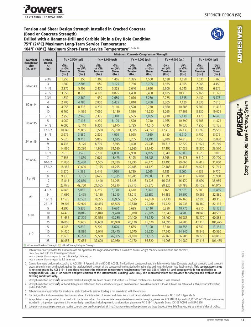
Tension and Shear Design Strength Installed in Cracked Concrete(Bond or Concrete Strength)Drilled with a Hammer-Drill and Carbide Bit in a Dry Hole Condition75°F (24°C) Maximum Long-Term Service Temperature; 104°F (40°C) Maximum Short-Term Service Temperature1,2,3,4,5,6,7,8
Nominal Rod/Rebar
Size(in. or #)
Embed.Depth
hef
(in.)
Minimum Concrete Compressive Strength
f'c = 2,500 (psi) f'c = 3,000 (psi) f'c = 4,000 (psi) f'c = 6,000 (psi) f'c = 8,000 (psi)
φNcb
or φNa
Tension(lbs.)
φVcb
or φVcp
Shear(lbs.)
φNcb
or φNa
Tension(lbs.)
φVcb
or φVcp
Shear(lbs.)
φNcb
or φNa
Tension(lbs.)
φVcb
or φVcp
Shear(lbs.)
φNcb
or φNa
Tension(lbs.)
φVcb
or φVcp
Shear(lbs.)
φNcb
or φNa
Tension(lbs.)
φVcb
or φVcp
Shear(lbs.)
3/8 or #3
2-3/8 1,250 1,350 1,305 1,405 1,395 1,500 1,530 1,650 1,635 1,7603 1,580 2,805 1,650 3,125 1,760 3,705 1,935 4,165 2,065 4,450
4-1/2 2,370 5,105 2,470 5,325 2,640 5,690 2,900 6,245 3,100 6,6757-1/2 3,950 8,510 4,120 8,875 4,400 9,480 4,835 10,410 5,165 11,120
1/2 or #4
2-3/4 1,830 2,360 1,930 2,680 2,070 3,280 2,275 4,355 2,430 5,1754 2,705 4,785 2,820 5,435 3,010 6,460 3,305 7,120 3,535 7,6106 4,055 8,735 4,230 9,110 4,520 9,730 4,960 10,685 5,300 11,41510 6,760 14,560 7,050 15,180 7,530 16,220 8,265 17,805 8,830 19,025
5/8 or #5
3-1/8 2,250 2,940 2,375 3,340 2,585 4,085 2,910 5,430 3,170 6,6405 4,060 7,135 4,230 8,105 4,520 9,740 4,965 10,690 5,305 11,425
7-1/2 6,090 13,110 6,350 13,675 6,785 14,610 7,445 16,035 7,955 17,13512-1/2 10,145 21,855 10,580 22,790 11,305 24,350 12,410 26,730 13,260 28,555
3/4 or #6
3-1/2 2,675 3,580 2,820 4,070 3,065 4,980 3,450 6,610 3,750 8,0756 5,625 9,710 5,865 11,035 6,265 13,495 6,880 14,815 7,350 15,8309 8,435 18,170 8,795 18,945 9,400 20,245 10,315 22,220 11,025 23,74015 14,060 30,280 14,660 31,580 15,665 33,740 17,195 37,035 18,370 39,570
7/8 or #7
3-1/2 2,610 3,525 2,750 4,000 2,980 4,895 3,340 6,500 3,620 7,8007 7,355 11,860 7,670 13,475 8,195 16,485 8,995 19,375 9,610 20,700
10-1/2 11,030 23,430 11,505 24,780 12,290 26,475 13,490 29,060 14,415 31,05017-1/2 18,385 39,600 19,175 41,295 20,485 44,120 22,485 48,435 24,025 51,745
1 or #8
4 3,270 4,365 3,440 4,960 3,730 6,065 4,185 8,060 4,535 9,7708 9,230 14,105 9,625 16,025 10,285 19,600 11,290 24,315 12,060 25,98012 13,845 27,860 14,440 31,095 15,425 33,225 16,935 36,470 18,090 38,96520 23,075 49,700 24,065 51,830 25,710 55,375 28,220 60,785 30,155 64,945
#9
4-1/2 4,045 5,080 4,255 5,770 4,610 7,060 5,165 9,375 5,600 11,4659 11,680 16,465 12,180 18,710 13,015 22,880 14,285 30,390 15,265 32,880
13-1/2 17,525 32,530 18,275 36,955 19,525 42,050 21,430 46,160 22,895 49,31522-1/2 29,205 62,900 30,455 65,595 32,540 70,080 35,720 76,935 38,160 82,195
1-1/4
5 4,995 5,835 5,255 6,630 5,695 8,110 6,380 10,775 6,915 13,17510 14,420 18,845 15,040 21,410 16,070 26,185 17,640 34,780 18,845 40,59015 21,635 37,220 22,560 42,285 24,100 51,720 26,460 56,985 28,270 60,88525 36,055 77,655 37,600 80,980 40,170 86,520 44,095 94,980 47,115 101,475
#10
5 4,945 5,830 5,200 6,620 5,635 8,100 6,310 10,755 6,840 13,15510 14,420 18,880 15,040 21,445 16,070 26,230 17,640 34,840 18,845 40,59015 21,635 37,290 22,560 42,365 24,100 51,815 26,460 56,985 28,270 60,88525 36,055 77,655 37,600 80,980 40,170 86,520 44,095 94,980 47,115 101,475
■ - Concrete Breakout Strength ■ - Bond Strength/Pryout Strength
1. Tabular values are provided for illustration and are applicable for single anchors installed in cracked normal-weight concrete with minimum slab thickness, ha = hmin, and with the following conditions: - ca1 is greater than or equal to the critical edge distance, cac
- ca2 is greater than or equal to 1.5 times ca1.2. Calculations were performed according to ACI 318-11 Appendix D and ICC-ES AC308. The load level corresponding to the failure mode listed [Concrete breakout strength, bond strength/
pryout strength] must be checked against the tabulated steel strength of the corresponding threaded rod or rebar size and type, the lowest load level controls. This temperature range is not recognized by ACI 318-11 and does not meet the minimum temperature requirements from ACI 355.4 Table 8.1 and consequently is not applicable to design under ACI 318-11 or current and past editions of the International Building Code (IBC). The Tabulated values are provided for analysis and evaluation of existing conditions only.
3. Strength reduction factors (φ) for concrete breakout strength are based on ACI 318 Section 9.2 for load combinations. Condition B was assumed.4. Strength reduction factors (φ) for bond strength are determined from reliability testing and qualification in accordance with ICC-ES AC308 and are tabulated in this product information
and in ESR-3576. 5. Tabular values are permitted for short-term, static loads only, seismic loading is not considered with these tables.6. For designs that include combined tension and shear, the interaction of tension and shear loads must be calculated in accordance with ACI 318-11 Appendix D.7. Interpolation is not permitted to be used with the tabular values. For intermediate base material compressive strengths, please see ACI 318-11 Appendix D, ICC-ES AC308 and information
included in this product supplement. For other design conditions including seismic considerations please see ACI 318-11 Appendix D and ICC-ES AC308 and ESR-3576.8. Long term concrete temperatures are roughly constant over significant periods of time. Short-term elevated temperatures are those that occur over brief intervals, e.g. as a result of diurnal cycling.
AD
HESIV
ES
www.powers.com 15
TECH MAN
UAL – ADHESIVES ©2016 PO
WERS VO
LUME 1 – REV. G
STRENGTH DESIGN (SD)
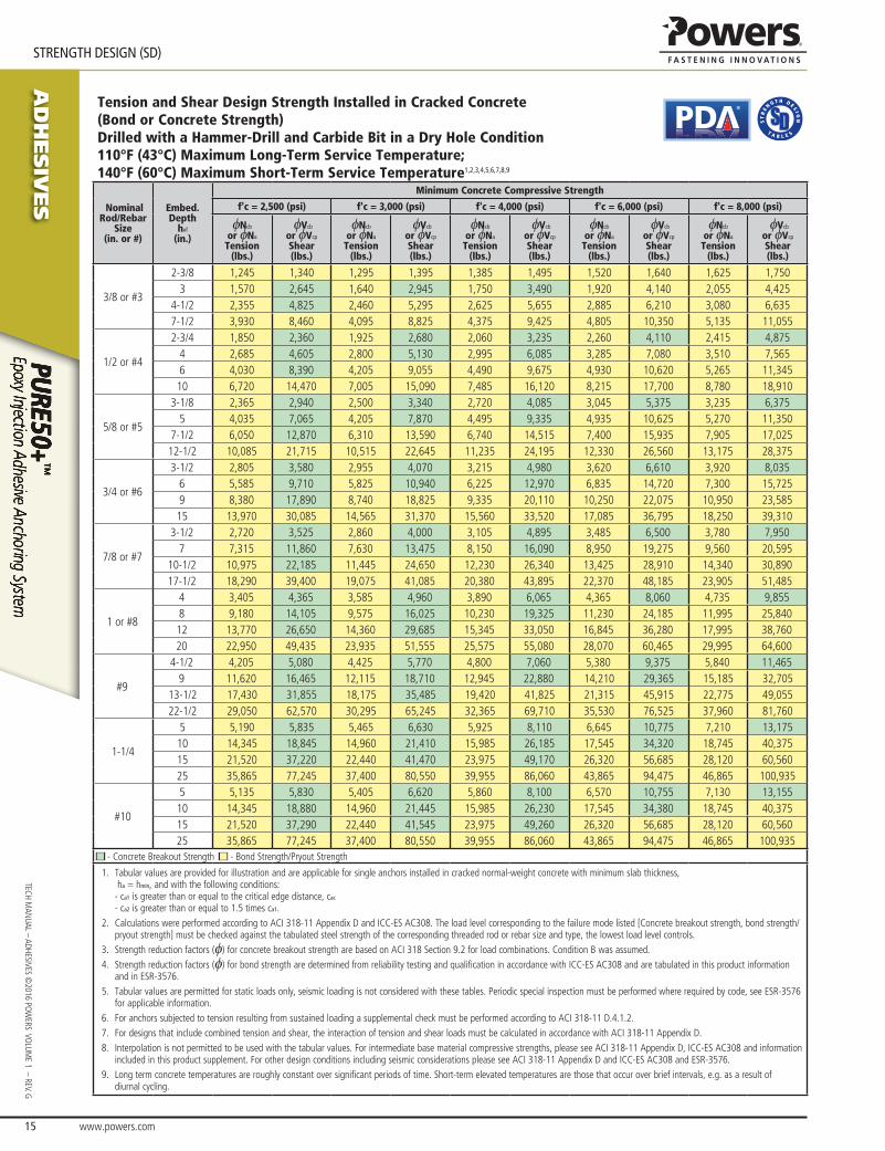
Tension and Shear Design Strength Installed in Cracked Concrete(Bond or Concrete Strength)Drilled with a Hammer-Drill and Carbide Bit in a Dry Hole Condition110°F (43°C) Maximum Long-Term Service Temperature; 140°F (60°C) Maximum Short-Term Service Temperature1,2,3,4,5,6,7,8,9
®
Nominal Rod/Rebar
Size(in. or #)
Embed.Depth
hef
(in.)
Minimum Concrete Compressive Strength
f'c = 2,500 (psi) f'c = 3,000 (psi) f'c = 4,000 (psi) f'c = 6,000 (psi) f'c = 8,000 (psi)
φNcb
or φNa
Tension(lbs.)
φVcb
or φVcp
Shear(lbs.)
φNcb
or φNa
Tension(lbs.)
φVcb
or φVcp
Shear(lbs.)
φNcb
or φNa
Tension(lbs.)
φVcb
or φVcp
Shear(lbs.)
φNcb
or φNa
Tension(lbs.)
φVcb
or φVcp
Shear(lbs.)
φNcb
or φNa
Tension(lbs.)
φVcb
or φVcp
Shear(lbs.)
3/8 or #3
2-3/8 1,245 1,340 1,295 1,395 1,385 1,495 1,520 1,640 1,625 1,7503 1,570 2,645 1,640 2,945 1,750 3,490 1,920 4,140 2,055 4,425
4-1/2 2,355 4,825 2,460 5,295 2,625 5,655 2,885 6,210 3,080 6,6357-1/2 3,930 8,460 4,095 8,825 4,375 9,425 4,805 10,350 5,135 11,055
1/2 or #4
2-3/4 1,850 2,360 1,925 2,680 2,060 3,235 2,260 4,110 2,415 4,8754 2,685 4,605 2,800 5,130 2,995 6,085 3,285 7,080 3,510 7,5656 4,030 8,390 4,205 9,055 4,490 9,675 4,930 10,620 5,265 11,34510 6,720 14,470 7,005 15,090 7,485 16,120 8,215 17,700 8,780 18,910
5/8 or #5
3-1/8 2,365 2,940 2,500 3,340 2,720 4,085 3,045 5,375 3,235 6,3755 4,035 7,065 4,205 7,870 4,495 9,335 4,935 10,625 5,270 11,350
7-1/2 6,050 12,870 6,310 13,590 6,740 14,515 7,400 15,935 7,905 17,02512-1/2 10,085 21,715 10,515 22,645 11,235 24,195 12,330 26,560 13,175 28,375
3/4 or #6
3-1/2 2,805 3,580 2,955 4,070 3,215 4,980 3,620 6,610 3,920 8,0356 5,585 9,710 5,825 10,940 6,225 12,970 6,835 14,720 7,300 15,7259 8,380 17,890 8,740 18,825 9,335 20,110 10,250 22,075 10,950 23,58515 13,970 30,085 14,565 31,370 15,560 33,520 17,085 36,795 18,250 39,310
7/8 or #7
3-1/2 2,720 3,525 2,860 4,000 3,105 4,895 3,485 6,500 3,780 7,9507 7,315 11,860 7,630 13,475 8,150 16,090 8,950 19,275 9,560 20,595
10-1/2 10,975 22,185 11,445 24,650 12,230 26,340 13,425 28,910 14,340 30,89017-1/2 18,290 39,400 19,075 41,085 20,380 43,895 22,370 48,185 23,905 51,485
1 or #8
4 3,405 4,365 3,585 4,960 3,890 6,065 4,365 8,060 4,735 9,8558 9,180 14,105 9,575 16,025 10,230 19,325 11,230 24,185 11,995 25,84012 13,770 26,650 14,360 29,685 15,345 33,050 16,845 36,280 17,995 38,76020 22,950 49,435 23,935 51,555 25,575 55,080 28,070 60,465 29,995 64,600
#9
4-1/2 4,205 5,080 4,425 5,770 4,800 7,060 5,380 9,375 5,840 11,4659 11,620 16,465 12,115 18,710 12,945 22,880 14,210 29,365 15,185 32,705
13-1/2 17,430 31,855 18,175 35,485 19,420 41,825 21,315 45,915 22,775 49,05522-1/2 29,050 62,570 30,295 65,245 32,365 69,710 35,530 76,525 37,960 81,760
1-1/4
5 5,190 5,835 5,465 6,630 5,925 8,110 6,645 10,775 7,210 13,17510 14,345 18,845 14,960 21,410 15,985 26,185 17,545 34,320 18,745 40,37515 21,520 37,220 22,440 41,470 23,975 49,170 26,320 56,685 28,120 60,56025 35,865 77,245 37,400 80,550 39,955 86,060 43,865 94,475 46,865 100,935
#10
5 5,135 5,830 5,405 6,620 5,860 8,100 6,570 10,755 7,130 13,15510 14,345 18,880 14,960 21,445 15,985 26,230 17,545 34,380 18,745 40,37515 21,520 37,290 22,440 41,545 23,975 49,260 26,320 56,685 28,120 60,56025 35,865 77,245 37,400 80,550 39,955 86,060 43,865 94,475 46,865 100,935
■ - Concrete Breakout Strength ■ - Bond Strength/Pryout Strength
1. Tabular values are provided for illustration and are applicable for single anchors installed in cracked normal-weight concrete with minimum slab thickness, ha = hmin, and with the following conditions: - ca1 is greater than or equal to the critical edge distance, cac
- ca2 is greater than or equal to 1.5 times ca1.2. Calculations were performed according to ACI 318-11 Appendix D and ICC-ES AC308. The load level corresponding to the failure mode listed [Concrete breakout strength, bond strength/
pryout strength] must be checked against the tabulated steel strength of the corresponding threaded rod or rebar size and type, the lowest load level controls.3. Strength reduction factors (φ) for concrete breakout strength are based on ACI 318 Section 9.2 for load combinations. Condition B was assumed. 4. Strength reduction factors (φ) for bond strength are determined from reliability testing and qualification in accordance with ICC-ES AC308 and are tabulated in this product information
and in ESR-3576.5. Tabular values are permitted for static loads only, seismic loading is not considered with these tables. Periodic special inspection must be performed where required by code, see ESR-3576
for applicable information.6. For anchors subjected to tension resulting from sustained loading a supplemental check must be performed according to ACI 318-11 D.4.1.2.7. For designs that include combined tension and shear, the interaction of tension and shear loads must be calculated in accordance with ACI 318-11 Appendix D.8. Interpolation is not permitted to be used with the tabular values. For intermediate base material compressive strengths, please see ACI 318-11 Appendix D, ICC-ES AC308 and information
included in this product supplement. For other design conditions including seismic considerations please see ACI 318-11 Appendix D and ICC-ES AC308 and ESR-3576.9. Long term concrete temperatures are roughly constant over significant periods of time. Short-term elevated temperatures are those that occur over brief intervals, e.g. as a result of
diurnal cycling.

www.powers.com 16
AD
HESIV
ES
STRENGTH DESIGN (SD)
TECH
MAN
UAL
– AD
HESI
VES
©20
16 P
OW
ERS
VO
LUM
E 1
– R
EV. G
Tension and Shear Design Strength Installed in Cracked Concrete(Bond or Concrete Strength)Drilled with a Hammer-Drill and Carbide Bit in a Dry Hole Condition110°F (43°C) Maximum Long-Term Service Temperature; 176°F (80°C) Maximum Short-Term Service Temperature1,2,3,4,5,6,7,8,9
®
Nominal Rod/Rebar
Size(in. or #)
Embed.Depth
hef
(in.)
Minimum Concrete Compressive Strength
f'c = 2,500 (psi) f'c = 3,000 (psi) f'c = 4,000 (psi) f'c = 6,000 (psi) f'c = 8,000 (psi)
φNcb
or φNa
Tension(lbs.)
φVcb
or φVcp
Shear(lbs.)
φNcb
or φNa
Tension(lbs.)
φVcb
or φVcp
Shear(lbs.)
φNcb
or φNa
Tension(lbs.)
φVcb
or φVcp
Shear(lbs.)
φNcb
or φNa
Tension(lbs.)
φVcb
or φVcp
Shear(lbs.)
φNcb
or φNa
Tension(lbs.)
φVcb
or φVcp
Shear(lbs.)
3/8 or #3
2-3/8 865 930 900 970 960 1,035 1,055 1,140 1,130 1,2153 1,090 2,305 1,140 2,450 1,215 2,620 1,335 2,875 1,425 3,070
4-1/2 1,635 3,525 1,705 3,675 1,825 3,930 2,000 4,310 2,140 4,6057-1/2 2,730 5,875 2,845 6,125 3,040 6,545 3,335 7,185 3,565 7,680
1/2 or #4
2-3/4 1,285 2,135 1,340 2,375 1,430 2,820 1,570 3,380 1,675 3,6104 1,865 4,015 1,945 4,190 2,080 4,480 2,285 4,915 2,440 5,2556 2,800 6,030 2,920 6,290 3,120 6,720 3,425 7,375 3,660 7,88010 4,665 10,050 4,865 10,480 5,200 11,195 5,705 12,290 6,095 13,135
5/8 or #5
3-1/8 1,750 2,790 1,825 3,110 1,950 3,685 2,140 4,610 2,290 4,9305 2,800 6,035 2,920 6,290 3,120 6,725 3,425 7,380 3,660 7,885
7-1/2 4,200 9,050 4,380 9,440 4,680 10,085 5,140 11,070 5,490 11,82512-1/2 7,005 15,085 7,305 15,730 7,805 16,805 8,565 18,450 9,150 19,710
3/4 or #6
3-1/2 2,180 3,515 2,265 3,920 2,410 4,645 2,625 5,655 2,790 6,0106 3,880 8,350 4,045 8,710 4,320 9,305 4,745 10,215 5,065 10,9159 5,815 12,530 6,065 13,065 6,480 13,960 7,115 15,325 7,600 16,37015 9,695 20,880 10,110 21,775 10,800 23,265 11,855 25,540 12,670 27,285
7/8 or #7
3-1/2 2,110 3,525 2,225 4,000 2,380 4,785 2,595 5,585 2,760 5,9407 5,080 10,615 5,295 11,405 5,660 12,185 6,210 13,375 6,635 14,290
10-1/2 7,615 16,405 7,945 17,110 8,485 18,280 9,315 20,065 9,955 21,44017-1/2 12,695 27,345 13,240 28,515 14,145 30,465 15,525 33,440 16,590 35,730
1 or #8
4 2,640 4,365 2,785 4,960 3,000 5,990 3,270 7,045 3,480 7,4908 6,370 12,755 6,645 14,210 7,100 15,290 7,790 16,785 8,325 17,93012 9,555 20,585 9,965 21,465 10,650 22,935 11,690 25,175 12,490 26,89520 15,930 34,305 16,610 35,775 17,745 38,225 19,480 41,960 20,815 44,830
#9
4-1/2 3,250 5,080 3,425 5,770 3,720 7,060 4,090 8,810 4,350 9,3709 8,065 15,245 8,410 16,985 8,985 19,350 9,860 21,240 10,535 22,695
13-1/2 12,095 26,050 12,615 27,165 13,475 29,025 14,795 31,860 15,805 34,04022-1/2 20,160 43,420 21,020 45,280 22,460 48,375 24,655 53,105 26,340 56,735
1-1/4
5 4,015 5,835 4,230 6,630 4,595 8,110 5,125 10,645 5,450 11,74010 9,955 17,820 10,380 19,850 11,090 23,535 12,175 26,225 13,010 28,02015 14,930 32,160 15,570 33,540 16,635 35,835 18,265 39,335 19,515 42,02525 24,885 53,605 25,955 55,900 27,730 59,725 30,440 65,560 32,520 70,045
#10
5 3,970 5,830 4,180 6,620 4,540 8,100 5,065 10,630 5,385 11,60010 9,955 17,850 10,380 19,885 11,090 23,575 12,175 26,225 13,010 28,02015 14,930 32,160 15,570 33,540 16,635 35,835 18,265 39,335 19,515 42,02525 24,885 53,605 25,955 55,900 27,730 59,725 30,440 65,560 32,520 70,045
■ - Concrete Breakout Strength ■ - Bond Strength/Pryout Strength
1. Tabular values are provided for illustration and are applicable for single anchors installed in cracked normal-weight concrete with minimum slab thickness, ha = hmin, and with the following conditions: - ca1 is greater than or equal to the critical edge distance, cac
- ca2 is greater than or equal to 1.5 times ca1.2. Calculations were performed according to ACI 318-11 Appendix D and ICC-ES AC308. The load level corresponding to the failure mode listed [Concrete breakout strength, bond strength/
pryout strength] must be checked against the tabulated steel strength of the corresponding threaded rod or rebar size and type, the lowest load level controls.3. Strength reduction factors (φ) for concrete breakout strength are based on ACI 318 Section 9.2 for load combinations. Condition B was assumed. 4. Strength reduction factors (φ) for bond strength are determined from reliability testing and qualification in accordance with ICC-ES AC308 and are tabulated in this product information
and in ESR-3576.5. Tabular values are permitted for static loads only, seismic loading is not considered with these tables. Periodic special inspection must be performed where required by code, see ESR-3576
for applicable information.6. For anchors subjected to tension resulting from sustained loading a supplemental check must be performed according to ACI 318-11 D.4.1.2.7. For designs that include combined tension and shear, the interaction of tension and shear loads must be calculated in accordance with ACI 318-11 Appendix D.8. Interpolation is not permitted to be used with the tabular values. For intermediate base material compressive strengths, please see ACI 318-11 Appendix D, ICC-ES AC308 and information
included in this product supplement. For other design conditions including seismic considerations please see ACI 318-11 Appendix D and ICC-ES AC308 and ESR-3576.9. Long term concrete temperatures are roughly constant over significant periods of time. Short-term elevated temperatures are those that occur over brief intervals, e.g. as a result of
diurnal cycling.

AD
HESIV
ES
www.powers.com 17
TECH MAN
UAL – ADHESIVES ©2016 PO
WERS VO
LUME 1 – REV. G
STRENGTH DESIGN (SD)
Tension Design of Steel Elements (Steel Strength)1,2
®
Steel Elements - Threaded Rod and Reinforcing Bar
Nominal Rod/Rebar
Size(in. or No.)
ASTM A36 and
ASTM F1554
Grade 36
ASTM F1554
Grade 55
ASTM A193 Grade B7 and ASTM F1554 Grade
105
ASTM A449
ASTM F568M
Class 5.8 and ISO 898-1
Class 5.8
ASTM F593 CW Stainless
(Types 304 and
316)
ASTM A193 Grade
B8/B8M, Class 1
Stainless (Types
304 and 316)
ASTM A193 Grade
B8/B8M2, Class 2B Stainless
(Types 304 and
316)
ASTM A615
Grade 75 Rebar
ASTM A615
Grade 60 Rebar
ASTM A706
Grade 60 Rebar
ASTM A615
Grade 40 Rebar
ØNsa
Tension(lbs.)
ØNsa
Tension(lbs.)
ØNsa
Tension(lbs.)
ØNsa
Tension(lbs.)
ØNsa
Tension(lbs.)
ØNsa
Tension(lbs.)
ØNsa
Tension(lbs.)
ØNsa
Tension(lbs.)
ØNsa
Tension(lbs.)
ØNsa
Tension(lbs.)
ØNsa
Tension(lbs.)
ØNsa
Tension(lbs.)
3/8 or #3 3,370 4,360 7,265 6,975 3,655 5,040 3,315 5,525 7,150 7,425 6,600 4,950
1/2 or #4 6,175 7,980 13,300 12,770 6,690 9,225 6,070 10,110 13,000 13,500 12,000 9,000
5/8 or #5 9,835 12,715 21,190 20,340 10,650 14,690 9,660 16,105 20,150 20,925 18,600 13,950
3/4 or #6 14,550 18,815 31,360 30,105 15,765 18,480 14,300 23,830 28,600 29,700 26,400 19,800
7/8 or #7 20,085 25,970 43,285 41,930 21,760 25,510 19,735 32,895 39,000 40,500 36,000 -
1 or #8 26,350 34,070 56,785 54,515 28,545 33,465 25,895 43,160 51,350 53,325 47,400 -
#9 - - - - - - - - 65,000 67,500 60,000 -
1-1/4 or #10 42,160 54,510 9,100 76,315 - 53,540 41,430 69,050 82,550 85,725 76,200 -
■ - Steel Strength
1. Steel tensile design strength according to ACI 318 Appendix D, φNsa = φ • Ase,N • futa
2. The tabulated steel design strength in tension must be checked against the bond strength/concrete capacity design strength to determine the controlling failure mode, the lowest load level controls.
Shear Design of Steel Elements (Steel Strength)1,2
Steel Elements - Threaded Rod and Reinforcing Bar
Nominal Rod/Rebar
Size(in. or No.)
ASTM A36 and
ASTM F1554
Grade 36
ASTM F1554
Grade 55
ASTM A193 Grade B7 and ASTM F1554 Grade
105
ASTM A449
ASTM F568M
Class 5.8 and ISO 898-1
Class 5.8
ASTM F593 CW Stainless
(Types 304 and
316)
ASTM A193 Grade
B8/B8M, Class 1
Stainless (Types
304 and 316)
ASTM A193 Grade
B8/B8M2, Class 2B Stainless
(Types 304 and
316)
ASTM A615
Grade 75 Rebar
ASTM A615
Grade 60 Rebar
ASTM A706
Grade 60 Rebar
ASTM A615
Grade 40 Rebar
ØVsa
Shear(lbs.)
ØVsa
Shear(lbs.)
ØVsa
Shear(lbs.)
ØVsa
Shear(lbs.)
ØVsa
Shear(lbs.)
ØVsa
Shear(lbs.)
ØVsa
Shear(lbs.)
ØVsa
Shear(lbs.)
ØVsa
Shear(lbs.)
ØVsa
Shear(lbs.)
ØVsa
Shear(lbs.)
ØVsa
Shear(lbs.)
3/8 or #3 1,755 2,265 3,775 3,625 2,025 2,790 1,725 2,870 3,960 3,860 3,430 2,575
1/2 or #4 3,210 4,150 6,915 6,640 3,705 5,110 3,155 5,255 7,200 7,020 6,240 4,680
5/8 or #5 5,115 6,610 11,020 10,575 5,900 8,135 5,025 8,375 11,160 10,880 9,670 7,255
3/4 or #6 7,565 9,785 16,305 15,655 8,730 10,235 7,435 12,390 15,840 15,445 13,730 10,295
7/8 or #7 10,445 13,505 22,505 21,805 12,050 14,130 10,265 17,105 21,600 21,060 18,720 -
1 or #8 13,700 17,715 29,525 28,345 15,810 18,535 13,465 22,445 28,440 27,730 24,650 -
#9 - - - - - - - - 36,000 35,100 31,200 -
1-1/4 or #10 21,920 28,345 4,735 39,685 - 29,655 21,545 35,905 45,720 44,575 39,625 -
■ - Steel Strength
1. Steel shear design strength according to ACI 318 Appendix D, φVsa = φ • 0.60 • Ase,V • futa
2. The tabulated steel design strength in shear must be checked against the bond strength/concrete capacity design strength to determine the controlling failure mode, the lowest load level controls.
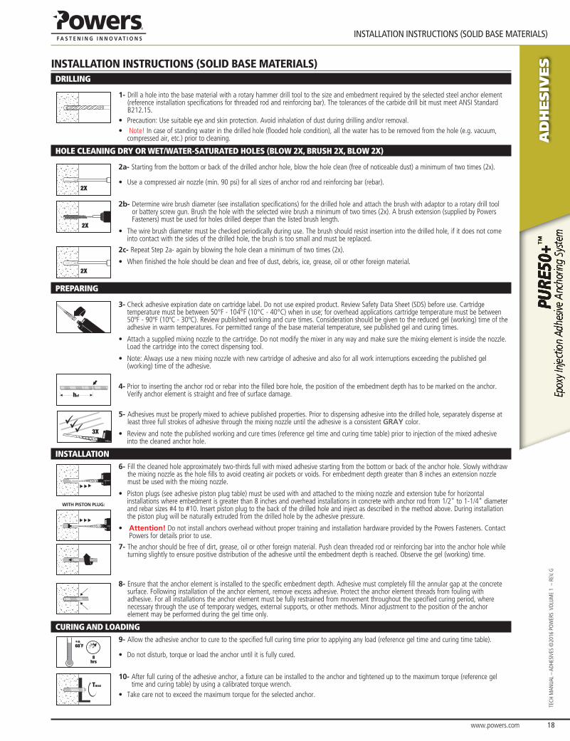
www.powers.com 18
AD
HESIV
ES
INSTALLATION INSTRUCTIONS (SOLID BASE MATERIALS)
TECH
MAN
UAL
– AD
HESI
VES
©20
16 P
OW
ERS
VO
LUM
E 1
– R
EV. G
INSTALLATION INSTRUCTIONS (SOLID BASE MATERIALS)DRILLING
1- Drill a hole into the base material with a rotary hammer drill tool to the size and embedment required by the selected steel anchor element (reference installation specifications for threaded rod and reinforcing bar). The tolerances of the carbide drill bit must meet ANSI Standard B212.15.
• Precaution: Use suitable eye and skin protection. Avoid inhalation of dust during drilling and/or removal.• Note! In case of standing water in the drilled hole (flooded hole condition), all the water has to be removed from the hole (e.g. vacuum,
compressed air, etc.) prior to cleaning.
HOLE CLEANING DRY OR WET/WATER-SATURATED HOLES (BLOW 2X, BRUSH 2X, BLOW 2X)
2X
2a- Starting from the bottom or back of the drilled anchor hole, blow the hole clean (free of noticeable dust) a minimum of two times (2x).
• Use a compressed air nozzle (min. 90 psi) for all sizes of anchor rod and reinforcing bar (rebar).
2X
2b- Determine wire brush diameter (see installation specifications) for the drilled hole and attach the brush with adaptor to a rotary drill tool or battery screw gun. Brush the hole with the selected wire brush a minimum of two times (2x). A brush extension (supplied by Powers Fasteners) must be used for holes drilled deeper than the listed brush length.
• The wire brush diameter must be checked periodically during use. The brush should resist insertion into the drilled hole, if it does not come into contact with the sides of the drilled hole, the brush is too small and must be replaced.
2X
2c- Repeat Step 2a- again by blowing the hole clean a minimum of two times (2x).
• When finished the hole should be clean and free of dust, debris, ice, grease, oil or other foreign material.
PREPARING
3- Check adhesive expiration date on cartridge label. Do not use expired product. Review Safety Data Sheet (SDS) before use. Cartridge temperature must be between 50°F - 104°F (10°C - 40°C) when in use; for overhead applications cartridge temperature must be between 50ºF - 90ºF (10ºC - 30ºC). Review published working and cure times. Consideration should be given to the reduced gel (working) time of the adhesive in warm temperatures. For permitted range of the base material temperature, see published gel and curing times.
• Attach a supplied mixing nozzle to the cartridge. Do not modify the mixer in any way and make sure the mixing element is inside the nozzle. Load the cartridge into the correct dispensing tool.
• Note: Always use a new mixing nozzle with new cartridge of adhesive and also for all work interruptions exceeding the published gel (working) time of the adhesive.
hef
4- Prior to inserting the anchor rod or rebar into the filled bore hole, the position of the embedment depth has to be marked on the anchor. Verify anchor element is straight and free of surface damage.
3X
5- Adhesives must be properly mixed to achieve published properties. Prior to dispensing adhesive into the drilled hole, separately dispense at least three full strokes of adhesive through the mixing nozzle until the adhesive is a consistent GRAY color.
• Review and note the published working and cure times (reference gel time and curing time table) prior to injection of the mixed adhesive into the cleaned anchor hole.
INSTALLATION6- Fill the cleaned hole approximately two-thirds full with mixed adhesive starting from the bottom or back of the anchor hole. Slowly withdraw
the mixing nozzle as the hole fills to avoid creating air pockets or voids. For embedment depth greater than 8 inches an extension nozzle must be used with the mixing nozzle.
• Piston plugs (see adhesive piston plug table) must be used with and attached to the mixing nozzle and extension tube for horizontal installations where embedment is greater than 8 inches and overhead installations in concrete with anchor rod from 1/2" to 1-1/4" diameter and rebar sizes #4 to #10. Insert piston plug to the back of the drilled hole and inject as described in the method above. During installation the piston plug will be naturally extruded from the drilled hole by the adhesive pressure.
• Attention! Do not install anchors overhead without proper training and installation hardware provided by the Powers Fasteners. Contact Powers for details prior to use.
WITH PISTON PLUG:
7- The anchor should be free of dirt, grease, oil or other foreign material. Push clean threaded rod or reinforcing bar into the anchor hole while turning slightly to ensure positive distribution of the adhesive until the embedment depth is reached. Observe the gel (working) time.
8- Ensure that the anchor element is installed to the specific embedment depth. Adhesive must completely fill the annular gap at the concrete surface. Following installation of the anchor element, remove excess adhesive. Protect the anchor element threads from fouling with adhesive. For all installations the anchor element must be fully restrained from movement throughout the specified curing period, where necessary through the use of temporary wedges, external supports, or other methods. Minor adjustment to the position of the anchor element may be performed during the gel time only.
CURING AND LOADINGe.g.
68˚F
8hrs
9- Allow the adhesive anchor to cure to the specified full curing time prior to applying any load (reference gel time and curing time table).
• Do not disturb, torque or load the anchor until it is fully cured.
Tmax
10- After full curing of the adhesive anchor, a fixture can be installed to the anchor and tightened up to the maximum torque (reference gel time and curing table) by using a calibrated torque wrench.
• Take care not to exceed the maximum torque for the selected anchor.
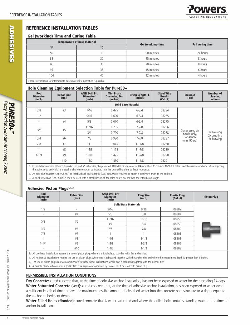
AD
HESIV
ES
www.powers.com 19
TECH MAN
UAL – ADHESIVES ©2016 PO
WERS VO
LUME 1 – REV. G
REFERENCE INSTALLATION TABLES
REFERENCE INSTALLATION TABLES
Gel (working) Time and Curing TableTemperature of base material
Gel (working) time Full curing timeºF ºC
50 10 90 minutes 24 hours
68 20 25 minutes 8 hours
86 30 20 minutes 8 hours
95 35 15 minutes 6 hours
104 40 12 minutes 4 hours
Linear interpolation for intermediate base material temperature is possible.
Hole Cleaning Equipment Selection Table for Pure50+Rod
Diameter(inch)
Rebar Size(No.)
ANSI Drill BitDiameter1
(inch)
Min. BrushDiameter, Dmin
(inches)
Brush Length, L(inches)
Steel WireBrush2,3
(Cat. #)
Blowout Tool
Number of cleaning actions
Solid Base Material
3/8 #3 7/16 0.475 6-3/4 08284
Compressed air nozzle only,Cat #8292
(min. 90 psi)
2x blowing2x brushing2x blowing
1/2 - 9/16 0.600 6-3/4 08285
- #4 5/8 0.670 6-3/4 08275
5/8 #511/16 0.735 7-7/8 08286
3/4 0.790 7-7/8 08278
3/4 #6 7/8 0.920 7-7/8 08287
7/8 #7 1 1.045 11-7/8 08288
1 #8 1-1/8 1.175 11-7/8 08289
1-1/4 #9 1-3/8 1.425 11-7/8 08290
- #10 1-1/2 1.550 11-7/8 08291
3. For installations with 5/8-inch threaded rod and #5 rebar size, the preferred ANSI drill bit diameter is 3/4-inch. If an 11/16-inch ANSI drill bit is used the user must check before injecting the adhesive to verify that the steel anchor element can be inserted into the cleaned borehole without resistance.
4. An SDS-plus adaptor (Cat. #08283) or Jacobs chuck style adaptor (Cat. #08296) is required to attach a steel wire brush to the drill tool.5. A brush extension (Cat. #08282) must be used with a steel wire brush for holes drilled deeper than the listed brush length.
Adhesive Piston Plugs1,2,3,4
RodDiameter
(inch)
Rebar Size(No.)
ANSI Drill BitDiameter
(inch)
Plug Size(inch)
Plastic Plug(Cat. #) Piston Plug
Solid Base Materials
1/2 - 9/16 9/16 08302
- #4 5/8 5/8 08304
5/8 #511/16 11/16 08258
3/4 3/4 08259
3/4 #6 7/8 7/8 08300
7/8 #7 1 1 08301
1 #8 1-1/8 1-1/8 08303
1-1/4 #9 1-3/8 1-3/8 08305
- #10 1-1/2 1-1/2 08309
1. All overhead installations require the use of piston plugs where one is tabulated together with the anchor size.2. All horizontal installations require the use of piston plugs where one is tabulated together with the anchor size and where the embedment depth is greater than 8 inches.3. The use of piston plugs is also recommended for underwater installations where one is tabulated together with the anchor size.4. A flexible plastic extension tube (cat# 08297) or equivalent approved by Powers must be used with piston plugs.
PERMISSIBLE INSTALLATION CONDITIONSDry Concrete: cured concrete that, at the time of adhesive anchor installation, has not been exposed to water for the preceding 14 days.Water-Saturated Concrete (wet): cured concrete that, at the time of adhesive anchor installation, has been exposed to water over a suffi cient length of time to have the maximum possible amount of absorbed water into the concrete pore structure to a depth equal to the anchor embedment depth.Water-Filled Holes (fl ooded): cured concrete that is water-saturated and where the drilled hole contains standing water at the time of anchor installation.

www.powers.com 20
AD
HESIV
ES
ORDERING INFORMATION
TECH
MAN
UAL
– AD
HESI
VES
©20
16 P
OW
ERS
VO
LUM
E 1
– R
EV. G
ORDERING INFORMATION
Pure50+ CartridgesCat No. Description Std. Carton Pallet
08600 Pure50+ 9 fl. oz Quik-Shot cartridge 12 432
08605 Pure50+ 21 fl. oz. cartridge 12 540
08651 Pure50+ 51 fl. oz. cartridge 8 216
One Pure50+ mixing nozzle is packaged with each cartridge.Pure50+ mixing nozzles must be used to ensure complete and proper mixing of the adhesive.
Cartridge System Mixing NozzlesCat. No. Description Std. Pkg. Std. Ctn.
08294 Extra mixing nozzle (with 8" extension) for Pure50+ Quik-Shot 2 24
08281 Mixing nozzle extension, 8" long 2 24
08297 Mixing nozzle extension, 20" long 1 12
08609 Extra high flow mixing nozzle (with 8" extension)for Pure50+ dual cartridge 2 24
Dispensing Tools for Injection AdhesiveCat No. Description Std. Box Std. Carton
08437 Manual caulking gun for Quik-Shot 1 12
08479 High performance caulking gun for Quik-Shot 1 12
08409 21 fl. oz. Standard metal manual tool 1 10
08421 21 fl. oz. High performance manual tool 1 10
08442 21 fl. oz. Battery powered tool (cordless) 1 -
08459 21 fl. oz. Pneumatic tool 1 -
08438 51 fl. oz. Pneumatic tool 1 -
Hole Cleaning Tools and AccessoriesCat No. Description Std. Box
08284 Wire brush for 7/16"ANSI hole(3/8" rod or #3 rebar), 6-3/4" length 1
08285 Wire brush for 9/16"ANSI hole(1/2" rod or #4 rebar), 6-3/4" length 1
08275 Wire brush for 5/8" ANSI hole(#4 rebar), 6-3/4" length 1
08286 Wire brush for 11/16"ANSI hole (5/8" rod or #5 rebar), 7-7/8" length 1
08278 Wire brush for 3/4"ANSI hole(5/8" rod or #5 rebar), 7-7/8" length 1
08287 Wire brush for 7/8"ANSI hole(3/4" rod or #6 rebar), 7-7/8" length 1
08288 Wire brush for 1"ANSI hole(7/8" rod or #7 rebar), 11-7/8" length 1
08289 Wire brush for 1-1/8"ANSI hole(1" rod or #8 rebar), 11-7/8" length 1
08290 Wire brush for 1-3/8"ANSI hole(1-1/4" rod or #9 rebar), 11-7/8" length 1
08291 Wire brush for 1-1/2"ANSI hole(#10 rebar), 11-7/8" length 1
08283 SDS-plus adapter for steel brushes 1
08296 Standard drill adapter for steel brushes(e.g. Jacobs Chuck) 1
08282 Steel brush extension, 12" length 108292 Air compressor nozzle with extension, 18" length 1
08465 Adjustable torque wrench with 1/2" square drive (10 to 150 ft.-lbs.) 1
08466 Adjustable torque wrench with 1/2" square drive (25 to 250 ft.-lbs.) 1
Adhesive Piston Plugs
Cat No. Description ANSI Drill Bit Dia.
Threaded Rod Dia.
Reinforcing Bar Size
Std.Bag
08302 9/16" Plug 9/16" 1/2" #4 10
08304 5/8" Plug 5/8" - #4 10
08258 11/16" Plug 11/16" 5/8" #5 10
08259 3/4" Plug 3/4" 5/8" #5 10
08300 7/8" Plug 7/8" 3/4" #6 10
08301 1" Plug 1" 7/8" #7 10
08303 1-1/8" Plug 1-1/8" 1" #8 10
08305 1-3/8" Plug 1-3/8" 1-1/4" #9 10
08309 1-1/2" Plug 1-1/2" - #10 10