pure sine wave inverter - gpelectric.com · pure sine wave inverter...
TRANSCRIPT
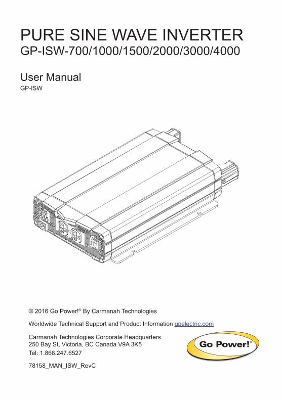
PURE SINE WAVE INVERTER GP-ISW-700/1000/1500/2000/3000/4000
User ManualGP-ISW
© 2016 Go Power!® By Carmanah Technologies
Worldwide Technical Support and Product Information gpelectric.com
Carmanah Technologies Corporate Headquarters250 Bay St, Victoria, BC Canada V9A 3K5Tel: 1.866.247.6527
78158_MAN_ISW_RevC
[page 2] | gpelectric.com
Congratulations on purchasing your Go Power! GP-ISW Inverter. The unit is a highly reliable DC-AC inverter system, designed with advanced power electronic and microprocessor technology offering the following features;
• Pure Sine wave output (THD <5%).• Intelligent power management software.• Load and temperature controlled cooling fan.• GP-SWR-A/GP-ISW-R management and control.• Dry contact terminals.• Advance protection features;
• Input over/under voltage protection.• Internal over temperature protection.• Input reverse polarity protection (fuse).• Output overload protection.• Output short-circuit protection.
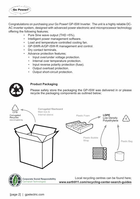
Product Packaging
Please safely store the packaging the GP-ISW was delivered in or please recycle the packaging components as outlined below;
CFBCFB
3 4 7
CFBCFB
3 4 7
Plastic Bag
Plastic Foam
Plastic BubbleWrap
LDPELow Density Polyethylene CFB
CFB
3 4 7
CFBCFB
3 4 7
CFBCFB
3 4 7
Corrugated fiberboardMain box &Internal sleeve
CFBCFB
3 4 7
CorrugatedRecycleswww.corrugated.org
www.earth911.com/recycling-center-search-guidesLocal recycling centres can be found here;Corporate Social Responsibility
Carmanah Technologies
gpelectric.com | [page 3]
1. CONTENTS
2. GENERAL INFORMATION .................................................................................................4
2.1 CAUTIONS / WARNINGS .................................................................................42.2 DISCLAIMERS................................................................................................102.3 GP-ISW KIT PARTS........................................................................................ 11 2.3.1 PARTS CHECKLIST ......................................................................... 112.4 GP-ISW FEATURES .......................................................................................122.5 UNIT DIMENSIONS ........................................................................................142.6 VOLTAGE AND TEMPERATURE PERFORMANCE ......................................15
3. INSTALLATION .................................................................................................................16
3.1 TYPICAL SYSTEM OVERVIEW .................................................................... 163.2 MOUNTING REQUIREMENTS ..................................................................... 203.3 DC WIRING ................................................................................................... 22 3.3.1 DC WIRING SIZING .........................................................................23 3.3.2 DC OVERCURRENT PROTECTION ...............................................24 3.3.3 PREPARING THE DC CABLES .......................................................24 3.3.4 DC CABLE CONNECTIONS ............................................................24 3.3.5 WIRING THE INVERTER TO THE BATTERIES ..............................25 3.3.6 DC GROUNDING .............................................................................263.4 AC WIRING.................................................................................................... 27 3.4.1 AC OUTPUT INTERFACE ................................................................27 3.4.2 GP-ISW 3000/4000 AC OUTPUT INTERFACE ................................27 3.4.3 GFCI (GROUND FAULT CIRCUIT INTERRUPTION) OUTLETS .....28
4. OPERATION ......................................................................................................................29
4.1 FINAL INSPECTION .......................................................................................294.2 TESTING THE INSTALLATION ......................................................................294.3 CONNECTING THE AC LOADS .....................................................................294.4 LED INDICATORS ..........................................................................................30 4.4.1 INPUT VOLTAGE LEVEL ..................................................................30 4.4.2 INVERTER STATUS TO DISPLAY FAULT CONDITION ..................314.5 FUNCTION SWITCH ......................................................................................31 4.5.1 OUTPUT VOLTAGE SELECTION (S1&S2) ......................................32 4.4.2 OUTPUT FREQUENCY SELECTION (S3) ......................................324.6 POWER SAVING SELECTION (S4) ...............................................................324.8 SHUTDOWN CONDITIONS ...........................................................................33
5. WARRANTY RETURN PROCEDURE ..............................................................................34
6. SPECIFICATIONS .............................................................................................................35
7. PRODUCT END OF LIFE & RECYCLING ........................................................................41
www.earth911.com/recycling-center-search-guides
[page 4] | gpelectric.com
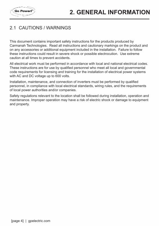
2.1 CAUTIONS / WARNINGS
This document contains important safety instructions for the products produced by Carmanah Technologies. Read all instructions and cautionary markings on the product and on any accessories or additional equipment included in the installation. Failure to follow these instructions could result in severe shock or possible electrocution. Use extreme caution at all times to prevent accidents.
All electrical work must be performed in accordance with local and national electrical codes. These instructions are for use by qualified personnel who meet all local and governmental code requirements for licensing and training for the installation of electrical power systems with AC and DC voltage up to 600 volts.
Installation, maintenance, and connection of inverters must be performed by qualified personnel, in compliance with local electrical standards, wiring rules, and the requirements of local power authorities and/or companies.
Safety regulations relevant to the location shall be followed during installation, operation and maintenance. Improper operation may have a risk of electric shock or damage to equipment and property.
2. GENERAL INFORMATION

gpelectric.com | [page 5]
GENERAL INFORMATION
General Safety
WARNING! Limitations on Use
CAUTION! Equipment Damage
This equipment is NOT intended for use with life support equipment or other medical equipment or devices.
This product is designed for indoor/compartment installation. It must not be exposed to any liquids, moisture of any type.
Only use components or accessories recommended or sold by Carmanah Technologies or its authorized agents.
IMPORTANTDo not attempt to install this equipment if it appears to be damaged in any way. See the Warranty section for instructions on returning the equipment.
WARNING! Hazard to Human Life
This type of notation indicates that the hazard could be harmful to human life.
WARNING! Shock Hazard Danger of shock or electrocution.
WARNING! Burn / Fire Hazard Danger of hot surface and/or fire.
CAUTION! Hazard to Equipment
This type of notation indicates that the hazard may cause damage to the equipment.
IMPORTANT
This type of notation indicates that the information provided is important to the installation, operation and/or maintenance of the equipment. Failure to follow the recommendations in such a notation could result in annulment of the equipment warranty.
i

[page 6] | gpelectric.com
GENERAL INFORMATION
Personal Safety
WARNING! Personal Injury
Use safe lifting techniques when lifting this equipment as recommended by the Occupational Safety and Health Association (OSHA) or other local codes.
Use standard safety equipment when working on this equipment, such as safety glasses, ear protection, steel-toed safety boots, safety hard hats, etc.
Use standard safety practices when working with electrical equipment. (Remove all jewelry, use insulated tools, wear cotton clothing, etc.)
Never work alone when installing or servicing this equipment. Have someone nearby that can assist if necessary.
Ensure that children, pets, and other animals are kept away from the inverter, solar arrays, battery bank, and utility grid components.
If the equipment is used in a manner not specified by the manufacturer, the protection provided by the equipment may be impaired.

GENERAL INFORMATION
Equipment Safety
WARNING! Lethal Voltage
Review the system configuration to identify all possible sources of energy. Ensure ALL sources of power are disconnected before performing any installation or maintenance on this equipment. Confirm that the terminals are de-energized using a validated voltmeter (rated for a minimum 1000 VAC and 1000 VDC) to verify the de-energized condition.
Do not perform any servicing other than that specified in the installation instructions unless qualified to do so, or have been instructed to do so by Carmanah Technologies Technical Support personnel.
To avoid electric shock, disconnect the DC input and AC input of the inverter at least 5 minutes before performing any installation or maintenance.
Do not tighten the AC and DC terminals or pull on the AC and DC wiring when the inverter is running.
WARNING! Fire Hazard
Do not keep combustible or flammable materials in the same room with the equipment. Some products contain relays with moving parts and are not ignition-protected.
Ensure AC, DC, and ground cable sizes conform to local codes. See product manuals for minimum size requirements.
Ensure all conductors are in good condition.
Do not operate the unit with damaged or substandard cabling.
CAUTION! Equipment Damage
When connecting cables from the inverter to the battery terminals, ensure the proper polarity is observed. Connecting the cables incorrectly can damage or destroy the equipment and void the product warranty.
Thoroughly inspect the equipment prior to energizing. Verify that no tools or equipment have been inadvertently left behind.
Keep all vents clear of obstructions that can prevent proper air flow around, or through, the unit.
CAUTION! Equipment Damage
Static electricity may damage electronic components. Take appropriate steps to prevent such damage to the inverter; otherwise the warranty may be annulled.
gpelectric.com | [page 7]

[page 8] | gpelectric.com
GENERAL INFORMATION
Battery Safety
WARNING! Explosion, Electrocution,
or Fire Hazard
Ensure the cables (conductors) are properly sized.
Ensure clearance requirements are strictly enforced around the batteries.
Ensure the area around the batteries is well ventilated and clean of debris.
Never smoke, or allow a spark or flame near, the batteries.
Always use insulated tools. Avoid dropping tools onto batteries or other electrical parts.
Never charge a frozen battery.
Never use old or untested batteries. Check each battery’s label for age, type, and date code to ensure all batteries are identical.
If a battery must be removed, always remove the grounded terminal from the battery first. Make sure all devices are de-energized or disconnected to avoid causing a spark.

gpelectric.com | [page 9]
IMPORTANT
Use the battery types recommended by Carmanah Technologies. Follow the battery manufacturer’s recommendations for installation and maintenance.
Insulate batteries as appropriate against freezing temperatures. A discharged battery will freeze more easily than a charged one.
If a remote or automatic generator control system is used, disable the starting circuit and/or disconnect the generator from its starting battery while performing maintenance to prevent accidental starting.
Wear complete eye and clothing protection when working with batteries. Avoid touching bare skin or eyes while working near batteries.
Keep plenty of fresh water and soap nearby in case battery acid contacts skin, clothing, or eyes.
If battery acid contacts skin or clothing, wash immediately with soap and water. If acid enters the eye, immediately flood it with running cold water for at least 20 minutes and get medical attention as soon as possible.
CAUTION! Equipment Damage
When connecting cables from the inverter to the battery terminals, ensure the proper polarity is observed. Connecting the cables incorrectly can damage or destroy the equipment and void the product warranty.
Thoroughly inspect the equipment prior to energizing. Verify that no tools or equipment have been inadvertently left behind.
Ensure clearance requirements are strictly enforced.
Keep all vents clear of obstructions that can prevent proper air flow around, or through, the unit.
CAUTION! Equipment Damage
Static electricity may damage electronic components. Take appropriate steps to prevent such damage to the inverter; otherwise the warranty may be annulled.
i
[page 10] | gpelectric.com
2.2 DISCLAIMERS
IMPORTANT: Please follow installation and wiring instructions exactly as outlined to ensure safety. We recommend installation by an RV/marine technician or professional electrician to ensure adherence to relevant electrical codes. We have made every reasonable effort to ensure the accuracy of the instructions in this manual, but Carmanah does not guarantee that the information is error free, nor do we make any other representation, warranty or guarantee that the information is accurate, correct, reliable or current. The specifications in this manual are for reference purposes only and are subject to change without notice. For additional information please see www.gpelectric.com.
DISCLAIMER: Carmanah disclaims liability for any direct, indirect or incidental damages caused by, or in case of, installation not performed following the instructions and cautions in this manual. Carmanah will refuse requests for exchanges or returns, resulting from the purchase and installation of items which do not comply with local codes. To avoid such concerns Carmanah recommends installation by a professional electrician or RV technician. Examples that are shown within this manual are for illustrative purposes only.
GENERAL INFORMATION
gpelectric.com | [page 11]
GENERAL INFORMATION
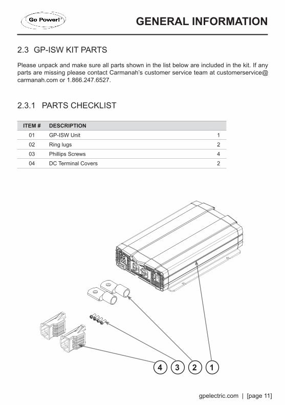
2.3 GP-ISW KIT PARTS
Please unpack and make sure all parts shown in the list below are included in the kit. If any parts are missing please contact Carmanah’s customer service team at [email protected] or 1.866.247.6527.
2.3.1 PARTS CHECKLIST
ITEM # DESCRIPTION01 GP-ISW Unit 1
02 Ring lugs 2
03 Phillips Screws 4
04 DC Terminal Covers 2
2 134

[page 12] | gpelectric.com
A
A
A
B
C
D
B
C
D
B
C
D
E
F
E
F
E
F
A
BE
DC
A
BE
DC
A
B
E
D
C
GENERAL INFORMATION
2.4 GP-ISW FEATURES
D
E
C
B
A Power saving adjustment - This dial is used to adjust the power saving function, it is used to set the input and wake up power thresholds (see page 33).
Function Switch - This dip switch is used to select between different voltages, frequencies and to turn the power saving mode ON and OFF (see page 31).
Function LEDs - These 3 LEDs are used to display (1) Input Voltage Level, (2) Output Load Level, (3) Fault Conditions (see page 30).
AC Output Socket or Output Terminal (3000W and 4000W only) - Use these sockets/terminal to connect the AC loads (appliances) to the Inverter.
ON / OFF / REMOTE- Use this button to turn the inverter ON, OFF or to switch the inverter into REMOTE MODE.

gpelectric.com | [page 13]
GENERAL INFORMATION
Remote port - Use this port to connect the optional remote control unit to the Inverter.
Remote control green terminal - This terminal may be connected to a form C relay for “FAULT” indication. When “FAULT” occurs, the relay switches.
Chassis Ground - Use this connection to ground the exposed chassis of the inverter to the chasis ground.
DC Input Connector - Use these connection points to secure the battery bank negative and positive cables to the Inverter. Always ensure the DC terminal covers are used to protect the terminals.
4
3
2
1
1
1
2 3
2
34
4
4 4
4
1
2
3
[page 14] | gpelectric.com
DC Input Side
DC Input Side
AC Output SideAC Output Side
ISW-700/1000
ISW-1500/2000/3000/4000
D
E
A
B
C
E
F
FA
D
B
C
F
F
DC Input Side
DC Input Side
AC Output SideAC Output Side
ISW-700/1000
ISW-1500/2000/3000/4000
D
E
A
B
C
E
F
FA
D
B
C
F
F
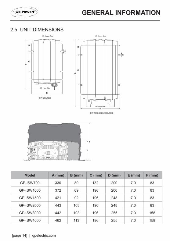
Model A (mm) B (mm) C (mm) D (mm) E (mm) F (mm)
GP-ISW700 330 80 132 200 7.0 83
GP-ISW1000 372 69 196 200 7.0 83
GP-ISW1500 421 92 196 248 7.0 83
GP-ISW2000 443 103 196 248 7.0 83
GP-ISW3000 442 103 196 255 7.0 158
GP-ISW4000 462 113 196 255 7.0 158
GENERAL INFORMATION
2.5 UNIT DIMENSIONS
gpelectric.com | [page 15]
0%10.5V
Continue
1 Min
1 Sec
1 Sec
21V42V
16V32V64V
Voltage (V)
Power (W
)
ISW-700~2000Power / Voltage Curve
16.5V33V66V
100%115%
175%
0%10.5V
Continue
1 Min
1 Sec
1 Sec
21V42V
16V32V64V
Voltage (V)
Power (W
)
ISW-3000/4000Power / Voltage Curve
16.5V33V66V
100%115%
200%
0%-20oC 0oC 40oC 60oC
ContinueOutput Power
1 Min
1 Sec
Power (W
)
Temperature (oC)ISW-700-2000
Power / Temperature Curve
100%
40%
115%
175%
0%-20oC 0oC 40oC 60oC
ContinueOutput Power
1 Min
1 Sec
Power (W
)
Temperature (oC)ISW-3000-4000
Power / Temperature Curve
100%
40%
115%
200%
0%10.5V
Continue
1 Min
1 Sec
1 Sec
21V42V
16V32V64V
Voltage (V)
Power (W
)
ISW-700~2000Power / Voltage Curve
16.5V33V66V
100%115%
175%
0%10.5V
Continue
1 Min
1 Sec
1 Sec
21V42V
16V32V64V
Voltage (V)
Power (W
)
ISW-3000/4000Power / Voltage Curve
16.5V33V66V
100%115%
200%
0%-20oC 0oC 40oC 60oC
ContinueOutput Power
1 Min
1 SecPow
er (W)
Temperature (oC)ISW-700-2000
Power / Temperature Curve
100%
40%
115%
175%
0%-20oC 0oC 40oC 60oC
ContinueOutput Power
1 Min
1 Sec
Power (W
)
Temperature (oC)ISW-3000-4000
Power / Temperature Curve
100%
40%
115%
200%
GENERAL INFORMATION
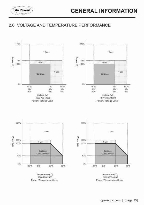
2.6 VOLTAGE AND TEMPERATURE PERFORMANCE
[page 16] | gpelectric.com
Cable to GP-ISW Unit
FM80
30 Amp Breaker
FuseBlock
Battery Bank
MC4 Connector
RefrigeratorVent Cover
100W or 160WSolar Panel
Mate 2
Legend
Remote
10 Ft Extension Cable 10AWG (Included)
25 Ft Cable 10AWG (Included)
For this system we recommend a minimum of 6 batteries / 600 Amp Hour
Battery Bank
RV Console
Area
Solar Controller
Cable to Battery Bank
Battery Bank
GP-ISWInverter
Solar Panels
Cables FromSolar Charge Controller
Internal View
GP-ISWRemote
Cable to Inverter
RefrigeratorVent Cover
100W or 160WSolar Panel
SolarController
FuseBlock
Inverter
InverterRemote
ACLoads
ACPanel
TransferSwitch
FuseBlock
Converter / Charger
Shore Power / Generator
AC Power OUTPUT - to RV appliances
Cables to / from Battery Bank
3. INSTALLATION
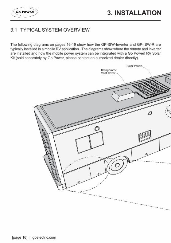
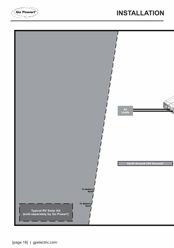
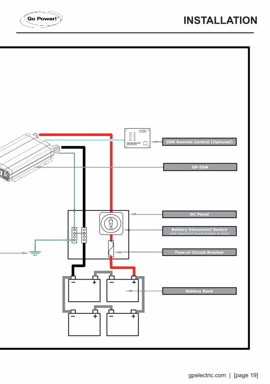
3.1 TYPICAL SYSTEM OVERVIEW
The following diagrams on pages 16-19 show how the GP-ISW-Inverter and GP-ISW-R are typically installed in a mobile RV application. The diagrams show where the remote and Inverter are installed and how the mobile power system can be integrated with a Go Power! RV Solar Kit (sold separately by Go Power, please contact an authorized dealer directly).

gpelectric.com | [page 17]
Cable to GP-ISW Unit
FM80
30 Amp Breaker
FuseBlock
Battery Bank
MC4 Connector
RefrigeratorVent Cover
100W or 160WSolar Panel
Mate 2
Legend
Remote
10 Ft Extension Cable 10AWG (Included)
25 Ft Cable 10AWG (Included)
For this system we recommend a minimum of 6 batteries / 600 Amp Hour
Battery Bank
RV Console
Area
Solar Controller
Cable to Battery Bank
Battery Bank
GP-ISWInverter
Solar Panels
Cables FromSolar Charge Controller
Internal View
GP-ISWRemote
Cable to Inverter
RefrigeratorVent Cover
100W or 160WSolar Panel
SolarController
FuseBlock
Inverter
InverterRemote
ACLoads
ACPanel
TransferSwitch
FuseBlock
Converter / Charger
Shore Power / Generator
AC Power OUTPUT - to RV appliances
Cables to / from Battery Bank
INSTALLATION
[page 18] | gpelectric.com
ON
OFF
Sub Panel
ISW Remote Control (Optional)
Solar Panel Solar Panel
Solar Charge Controller
RefrigeratorVent Cover
or Cable Entry Plate
Fuse
Battery Disconnect Switch(not required if circuit breaker is used)
Battery Bank
Fuse or Circuit Breaker
GP-ISW
To BatteryBank
To BatteryBank
DC Panel
Earth Ground (RV Ground)
ACLoads
INSTALLATION
gpelectric.com | [page 19]
ON
OFF
Sub Panel
ISW Remote Control (Optional)
Solar Panel Solar Panel
Solar Charge Controller
RefrigeratorVent Cover
or Cable Entry Plate
Fuse
Battery Disconnect Switch(not required if circuit breaker is used)
Battery Bank
Fuse or Circuit Breaker
GP-ISW
To BatteryBank
To BatteryBank
DC Panel
Earth Ground (RV Ground)
ACLoads
INSTALLATION
[page 20] | gpelectric.com
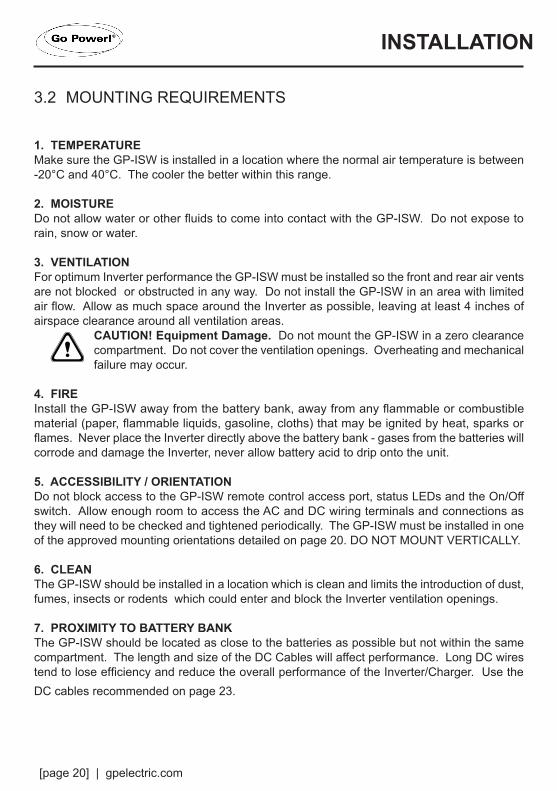
3.2 MOUNTING REQUIREMENTS
1. TEMPERATUREMake sure the GP-ISW is installed in a location where the normal air temperature is between -20°C and 40°C. The cooler the better within this range.
2. MOISTUREDo not allow water or other fluids to come into contact with the GP-ISW. Do not expose to rain, snow or water.
3. VENTILATIONFor optimum Inverter performance the GP-ISW must be installed so the front and rear air vents are not blocked or obstructed in any way. Do not install the GP-ISW in an area with limited air flow. Allow as much space around the Inverter as possible, leaving at least 4 inches of airspace clearance around all ventilation areas.
CAUTION! Equipment Damage. Do not mount the GP-ISW in a zero clearance compartment. Do not cover the ventilation openings. Overheating and mechanical failure may occur.
4. FIREInstall the GP-ISW away from the battery bank, away from any flammable or combustible material (paper, flammable liquids, gasoline, cloths) that may be ignited by heat, sparks or flames. Never place the Inverter directly above the battery bank - gases from the batteries will corrode and damage the Inverter, never allow battery acid to drip onto the unit.
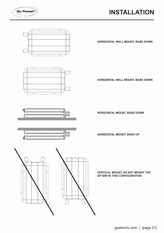
5. ACCESSIBILITY / ORIENTATIONDo not block access to the GP-ISW remote control access port, status LEDs and the On/Off switch. Allow enough room to access the AC and DC wiring terminals and connections as they will need to be checked and tightened periodically. The GP-ISW must be installed in one of the approved mounting orientations detailed on page 20. DO NOT MOUNT VERTICALLY.
6. CLEANThe GP-ISW should be installed in a location which is clean and limits the introduction of dust, fumes, insects or rodents which could enter and block the Inverter ventilation openings.
7. PROXIMITY TO BATTERY BANKThe GP-ISW should be located as close to the batteries as possible but not within the same compartment. The length and size of the DC Cables will affect performance. Long DC wires tend to lose efficiency and reduce the overall performance of the Inverter/Charger. Use the DC cables recommended on page 23.
INSTALLATION
gpelectric.com | [page 21]
HORIZONTAL WALL MOUNT, BASE DOWN
HORIZONTAL WALL MOUNT, BASE DOWN
HORIZONTAL MOUNT, BASE DOWN
HORIZONTAL MOUNT, BASE UP
VERTICAL MOUNT, DO NOT MOUNT THE GP-ISW IN THIS CONFIGURATION
INSTALLATION
[page 22] | gpelectric.com
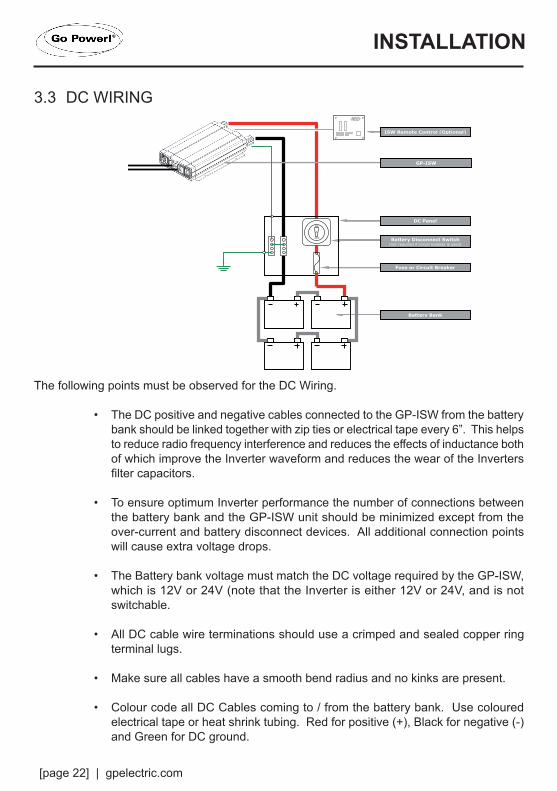
3.3 DC WIRING
INSTALLATION
ON
OFF
Sub Panel
ISW Remote Control (Optional)
Solar Panel Solar Panel
Solar Charge Controller
RefrigeratorVent Cover
or Cable Entry Plate
Fuse
Battery Disconnect Switch(not required if circuit breaker is used)
Battery Bank
Fuse or Circuit Breaker
GP-ISW
To BatteryBank
To BatteryBank
DC Panel
Earth Ground (RV Ground)
ACLoads
The following points must be observed for the DC Wiring.
• The DC positive and negative cables connected to the GP-ISW from the battery bank should be linked together with zip ties or electrical tape every 6”. This helps to reduce radio frequency interference and reduces the effects of inductance both of which improve the Inverter waveform and reduces the wear of the Inverters filter capacitors.
• To ensure optimum Inverter performance the number of connections between the battery bank and the GP-ISW unit should be minimized except from the over-current and battery disconnect devices. All additional connection points will cause extra voltage drops.
• The Battery bank voltage must match the DC voltage required by the GP-ISW, which is 12V or 24V (note that the Inverter is either 12V or 24V, and is not switchable.
• All DC cable wire terminations should use a crimped and sealed copper ring terminal lugs.
• Make sure all cables have a smooth bend radius and no kinks are present.
• Colour code all DC Cables coming to / from the battery bank. Use coloured electrical tape or heat shrink tubing. Red for positive (+), Black for negative (-) and Green for DC ground.
gpelectric.com | [page 23]
INSTALLATION
3.3.1 DC WIRING SIZING
The distance between the battery bank and the GP-ISW should be as short as possible to achieve maximum efficiency and to reduce fire hazards. The size of the cable should be thick enough to limit the voltage drop to less than 2% when carrying the maximum input current to prevent frequent low-input voltage warnings and shutdown. Only use high quality copper wire.
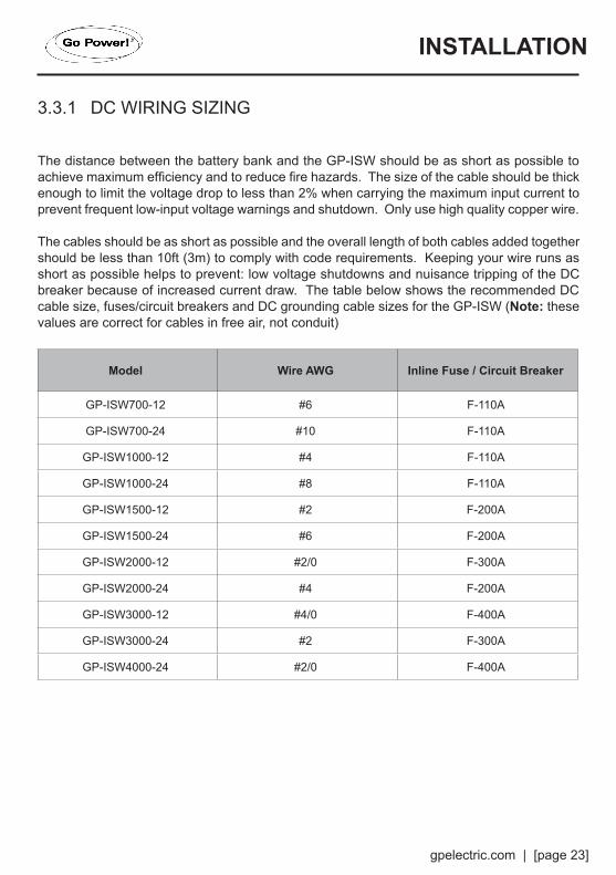
The cables should be as short as possible and the overall length of both cables added together should be less than 10ft (3m) to comply with code requirements. Keeping your wire runs as short as possible helps to prevent: low voltage shutdowns and nuisance tripping of the DC breaker because of increased current draw. The table below shows the recommended DC cable size, fuses/circuit breakers and DC grounding cable sizes for the GP-ISW (Note: these values are correct for cables in free air, not conduit)
Model Wire AWG Inline Fuse / Circuit Breaker
GP-ISW700-12 #6 F-110A
GP-ISW700-24 #10 F-110A
GP-ISW1000-12 #4 F-110A
GP-ISW1000-24 #8 F-110A
GP-ISW1500-12 #2 F-200A
GP-ISW1500-24 #6 F-200A
GP-ISW2000-12 #2/0 F-300A
GP-ISW2000-24 #4 F-200A
GP-ISW3000-12 #4/0 F-400A
GP-ISW3000-24 #2 F-300A
GP-ISW4000-24 #2/0 F-400A
[page 24] | gpelectric.com
3.3.2 DC OVERCURRENT PROTECTION AND DC DISCONNECT
Batteries are capable of providing very large currents in case of a short circuit, if this occurs with no DC overcurrent protection, it will result in overheating and melting of the cables and possibly serious injury and/or fire.
DC overcurrent protection is not included with the GP-ISW Inverters. It must be installed between the Inverter and battery bank for safety reasons and to comply with code regulations.
The fuse should be as close to the positive battery terminal as possible. Use Bussmann ANN Class T series fuses (will also require Fuse Block 4164) or equivalent. Ideally the fuse/circuit breaker should be installed within 18” (45cm of the battery). The fuse required for DC Cable lengths up to 10ft is detailed in the above table.
In all installations a battery disconnect switch is required, if you install a circuit breaker for overcurrent protection this will suffice as a disconnect switch. If you install a fuse for overcurrent protection then a separate disconnect switch will need to be installed.
3.3.3 PREPARING THE DC CABLES
Go Power! supplies 2 ring lugs with the GP-ISW which can be used for the Inverter end of the DC Cables. Source the correct ring terminals for the batteries you are using.
• Cut the negative and positive cables to the required length.
• Strip off enough insulation so you can install the ring lugs provided.
• Use the correct crimp connector to install the ring lugs.
• Attach the connectors to both ends of both cables. Make sure no stray wire strands protrude from the connectors.
3.3.4 DC CABLE CONNECTIONS
When installing the battery cable ring lug onto the GP-ISW DC terminal and the battery post - do not put anything between the ring lug and the metal surface. Incorrectly installed hardware causes a high resistance connection which could lead to poor Inverter/Charger performance and may melt the cable and terminal connections. Tighten the terminal connections securely (torque to 9 – 10 ft-lbs, 11.7 – 13 Nm) and periodically check the connections to make sure they remain tight and secure.
INSTALLATION
gpelectric.com | [page 25]
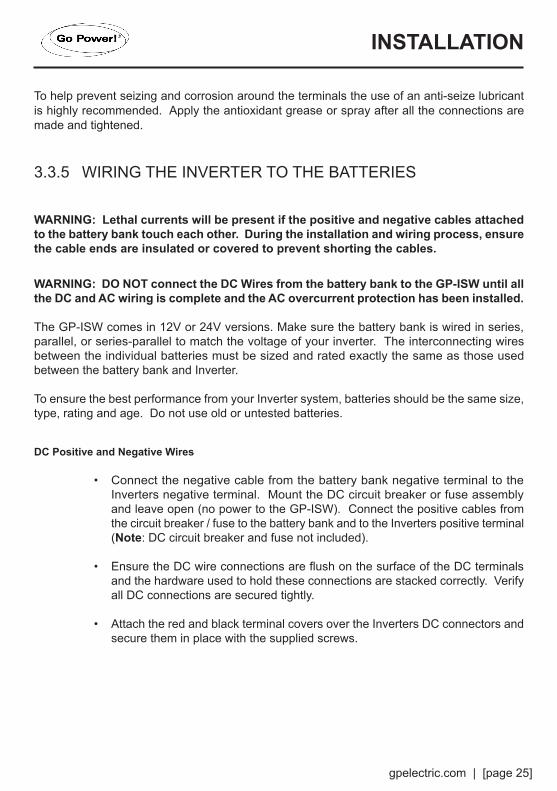
To help prevent seizing and corrosion around the terminals the use of an anti-seize lubricant is highly recommended. Apply the antioxidant grease or spray after all the connections are made and tightened.
3.3.5 WIRING THE INVERTER TO THE BATTERIES
WARNING: Lethal currents will be present if the positive and negative cables attached to the battery bank touch each other. During the installation and wiring process, ensure the cable ends are insulated or covered to prevent shorting the cables.
WARNING: DO NOT connect the DC Wires from the battery bank to the GP-ISW until all the DC and AC wiring is complete and the AC overcurrent protection has been installed.
The GP-ISW comes in 12V or 24V versions. Make sure the battery bank is wired in series, parallel, or series-parallel to match the voltage of your inverter. The interconnecting wires between the individual batteries must be sized and rated exactly the same as those used between the battery bank and Inverter.
To ensure the best performance from your Inverter system, batteries should be the same size, type, rating and age. Do not use old or untested batteries.
DC Positive and Negative Wires
• Connect the negative cable from the battery bank negative terminal to the Inverters negative terminal. Mount the DC circuit breaker or fuse assembly and leave open (no power to the GP-ISW). Connect the positive cables from the circuit breaker / fuse to the battery bank and to the Inverters positive terminal (Note: DC circuit breaker and fuse not included).
• Ensure the DC wire connections are flush on the surface of the DC terminals and the hardware used to hold these connections are stacked correctly. Verify all DC connections are secured tightly.
• Attach the red and black terminal covers over the Inverters DC connectors and secure them in place with the supplied screws.
INSTALLATION
[page 26] | gpelectric.com
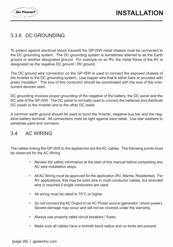
3.3.6 DC GROUNDING
To protect against electrical shock hazards the GP-ISW metal chassis must be connected to the DC grounding system. The DC grounding system is sometimes referred to as the Earth ground or another designated ground. For example on an RV, the metal frame of the RV is designated as the negative DC ground / RV ground.
The DC ground wire connection on the GP-ISW is used to connect the exposed chassis of the Inverter to the DC grounding system. Use copper wire that is either bare or provided with green insulation. The size of this conductor should be coordinated with the size of the over-current devices used.
DC grounding involves proper grounding of the negative of the battery, the DC panel and the DC side of the GP-ISW. The DC panel is normally used to connect the batteries and distribute DC power to the Inverter and to the other DC loads.
A common earth ground should be used to bond the Inverter, negative bus bar and the neg-ative battery terminal. All connections must be tight against bare metal. Use star washers to penetrate paint and corrosion.
3.4 AC WIRING
The cables linking the GP-ISW to the appliances are the AC cables. The following points must be observed for the AC Wiring
• Review the safety information at the start of this manual before completing any AC wire installation steps.
• All AC Wiring must be approved for the application (RV, Marine, Residential). For RV applications, this may be solid wire in multi-conductor cables, but stranded wire is required if single conductors are used.
• All wiring must be rated to 75°C or higher.
• Do not connect the AC Output to an AC Power source (generator / shore power). Severe damage may occur and will not be covered under the warranty.
• Always use properly rated circuit breakers / fuses.
• Make sure all cables have a smooth bend radius and no kinks are present.
INSTALLATION
gpelectric.com | [page 27]
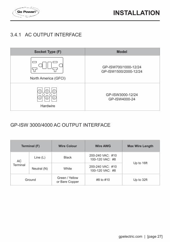
3.4.1 AC OUTPUT INTERFACE
Socket Type (F) Model
North America (GFCI)
GP-ISW700/1000-12/24GP-ISW1500/2000-12/24
Hardwire
GP-ISW3000-12/24GP-ISW4000-24
GP-ISW 3000/4000 AC OUTPUT INTERFACE
Terminal (F) Wire Colour Wire AWG Max Wire Length
AC Terminal
Line (L) Black 200-240 VAC: #10100-120 VAC: #8
Up to 16ft
Neutral (N) White 200-240 VAC: #10100-120 VAC: #8
Ground Green / Yellowor Bare Copper #8 to #10 Up to 32ft
INSTALLATION

[page 28] | gpelectric.com
3.4.2 GFCI (GROUND FAULT CIRCUIT INTERRUPTION) OUTLETS
Compliance with UL standards requires that Go Power! test and recommend specific GFCIs for use on the AC output of the GP-ISW. GFCIs shall be installed in the AC output wiring system to protect all branch circuits.
A GFCI is a device that de–energizes a circuit when a current exceeds a specified value that is less than that required to open the circuit breaker. GFCIs are intended to protect people from electric shocks and are usually required in wet or damp locations.
The table below lists GFCIs that have been tested and will function properly when connected to the AC output of the GP-ISW.
Manufacturer Model Number
Cooper Wiring Devices Type VGF20 Rated 125V, 20A
Leviton Mfg Co Inc Type 7899-W, Rated 125V, 20A
Hubbell Inc Wiring Device Dev Type GF20, Rated 125V, 20A
INSTALLATION

gpelectric.com | [page 29]
4. OPERATION4.1 FINAL INSPECTION
1. Verify all cables / conduit runs are secured with zip ties or other non-conductive cable clamps to prevent damage from vibration.
2. Ensure all cables that pass through walls, bulkheads or any other openings are protected against abrasion by using strain reliefs and/or grommets.
3. Check all AC, DC and ground connections are securely tightened, and if required covered with suitable anti-seizing grease.
4. Check all connections are secure in the main and sub panels - replace all covers.5. If required by code, have the installation inspected by an electrical inspector.
4.2 TESTING THE INSTALLATION
1. Apply battery power to the inverter by engaging the fuse or switching the breaker to the ON position.
2. Disconnect all AC loads from the inverter.3. Press the ON/OFF button. The inverter will carry out self-diagnosis and the LED’s will
also appear (various colors).4. Connect a 25W light bulb to the inverter output and verify it comes on and shines normally.5. Press the ON/OFF button. The inverter and LED lights will turn off.
4.3 CONNECTING THE AC LOADS
Calculate the total power consumption of the output load. Make sure that the total power con-sumption does not exceed the rated power. If the total power consumption is higher than the rated power of the inverter, remove the non-critical loads until the total power consumption is below the rated power.
[page 30] | gpelectric.com
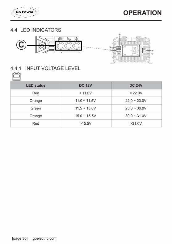
4.4 LED INDICATORS
4.4.1 INPUT VOLTAGE LEVEL
LED status DC 12V DC 24V
Red < 11.0V < 22.0V
Orange 11.0 ~ 11.5V 22.0 ~ 23.0V
Green 11.5 ~ 15.0V 23.0 ~ 30.0V
Orange 15.0 ~ 15.5V 30.0 ~ 31.0V
Red >15.5V >31.0V
A
A
A
B
C
D
B
C
D
B
C
D
E
F
E
F
E
F
A
BE
DC
A
BE
DC
A
B
E
D
C
A
A
A
B
C
D
B
C
D
B
C
D
E
F
E
F
E
F
A
BE
DC
A
BE
DC
A
B
E
D
C
OPERATION
gpelectric.com | [page 31]
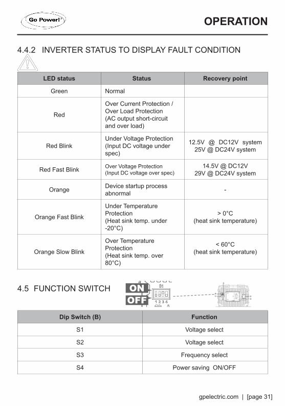
4.4.2 INVERTER STATUS TO DISPLAY FAULT CONDITION
LED status Status Recovery point
Green Normal
Red
Over Current Protection / Over Load Protection(AC output short-circuit and over load)
Red BlinkUnder Voltage Protection (Input DC voltage under spec)
12.5V @ DC12V system 25V @ DC24V system
Red Fast Blink Over Voltage Protection (Input DC voltage over spec)
14.5V @ DC12V29V @ DC24V system
Orange Device startup process abnormal -
Orange Fast Blink
Under Temperature Protection (Heat sink temp. under -20°C)
> 0°C(heat sink temperature)
Orange Slow Blink
Over Temperature Protection (Heat sink temp. over 80°C)
< 60°C(heat sink temperature)
4.5 FUNCTION SWITCH
Dip Switch (B) Function
S1 Voltage select
S2 Voltage select
S3 Frequency select
S4 Power saving ON/OFF
ONOFF
A
A
A
B
C
D
B
C
D
B
C
D
E
F
E
F
E
F
A
BE
DC
A
BE
DC
A
B
E
D
C
OPERATION
[page 32] | gpelectric.com
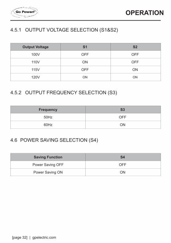
4.5.1 OUTPUT VOLTAGE SELECTION (S1&S2)
Output Voltage S1 S2
100V OFF OFF
110V ON OFF
115V OFF ON
120V ON ON
4.5.2 OUTPUT FREQUENCY SELECTION (S3)
Frequency S3
50Hz OFF
60Hz ON
4.6 POWER SAVING SELECTION (S4)
Saving Function S4
Power Saving OFF OFF
Power Saving ON ON
OPERATION

gpelectric.com | [page 33]
4.7 SHUTDOWN CONDITIONS
ModelOver Voltage (DC) Under
Voltage Alarm
Under Voltage (DC)
Shutdown Restart Shutdown Restart
12V 16.5V ± 0.3V
14.5V± 0.3V
10.5V ± 0.3V
10.5V ± 0.3V
12.5V± 0.3V
24V 33V ± 0.5V 29V ± 0.5V 21V± 0.5V 21V ± 0.5V 25V ± 0.5V
ModelOver Temperature Protection
Shutdown Restart
12V80°C 60°C
24V
OPERATION

[page 34] | gpelectric.com
5. WARRANTY RETURN PROCEDURE
The Go Power! warranty is valid against defects in materials and workmanship for the specific product warranty period. It is not valid against defects resulting from, but not limited to:
• Misuse and/or abuse, neglect or accident• Exceeding the unit’s design limits• Improper installation, including, but not limited to, improper environmental protection and improper hook-up• Acts of God, including lightning, floods, earthquakes, fire, and high winds• Damage in handling, including damage encountered during shipment
A warranty shall be considered void if the warranted product is in any way opened or altered. The warranty will be void if any eyelet, rivets, or other fasteners used to seal the unit are removed or altered, or if the unit’s serial number is in any way removed, altered, replaced, defaced, or rendered illegible.
Warranty Return ProcedureBefore contacting Go Power! customer service department, please read the “frequently asked questions” section of our website to troubleshoot the problem. If trouble persists:
1. Call your Go Power!® Technical Support team (1-866-247-6527) or2. Return defective product to place of purchase
Unless approved by Go Power! Management, all product shipped collect to Go Power! will be refused. Test items or items that are not under warranty, or units that are not defective, will be charged a minimum bench charge of ($50.00 US) plus taxes and shipping. A 15% restocking charge will be applied on goods returned and accepted as “new” stock.
An RMA number (Return Materials Authorization number) from Carmanah Customer Service is required prior to returning any Carmanah Products. Carmanah reserves the right to refuse any items sent to Carmanah without an associated RMA number. To obtain an RMA number, please contact [email protected] or Telephone 1-250-380-0052 or Fax 1-250-380-0062 worldwide – or Toll Free for US & Canada 1-866-247-6527. Out of WarrantyGo Power! electronic products are non-repairable, Go Power! does not perform repairs on its products nor does it contract out those repairs to a third party. Go Power! does not supply schematics or replacement parts for any of its electronic products.
gpelectric.com | [page 35]
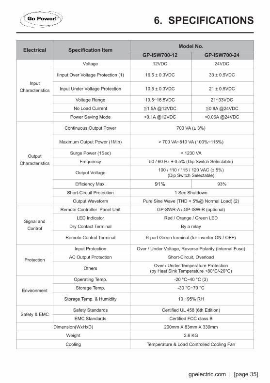
6. SPECIFICATIONS
Electrical Specification ItemModel No.
GP-ISW700-12 GP-ISW700-24
InputCharacteristics
Voltage 12VDC 24VDC
IInput Over Voltage Protection (1) 16.5 ± 0.3VDC 33 ± 0.5VDC
Input Under Voltage Protection 10.5 ± 0.3VDC 21 ± 0.5VDC
Voltage Range 10.5~16.5VDC 21~33VDC
No Load Current ≦1.5A @12VDC ≦0.8A @24VDC
Power Saving Mode <0.1A @12VDC <0.06A @24VDC
OutputCharacteristics
Continuous Output Power 700 VA (± 3%)
Maximum Output Power (1Min) > 700 VA~810 VA (100%~115%)
Surge Power (1Sec) < 1230 VA
Frequency 50 / 60 Hz ± 0.5% (Dip Switch Selectable)
Output Voltage 100 / 110 / 115 / 120 VAC (± 5%)(Dip Switch Selectable)
Efficiency Max. 91% 93%
Short-Circuit Protection 1 Sec Shutdown
Output Waveform Pure Sine Wave (THD < 5%@ Normal Load) (2)
Signal and Control
Remote Controller Panel Unit GP-SWR-A / GP-ISW-R (optional)
LED Indicator Red / Orange / Green LED
Dry Contact Terminal By a relay
Remote Control Terminal 6-port Green terminal (for inverter ON / OFF)
Protection
Input Protection Over / Under Voltage, Reverse Polarity (Internal Fuse)
AC Output Protection Short-Circuit, Overload
Others Over / Under Temperature Protection(by Heat Sink Temperature +80°C/-20°C)
Environment
Operating Temp. -20 °C~40 °C (3)
Storage Temp. -30 °C~70 °C
Storage Temp. & Humidity 10 ~95% RH
Safety & EMCSafety Standards Certified UL 458 (6th Edition)
EMC Standards Certified FCC class B
Dimension(WxHxD) 200mm X 83mm X 330mm
Weight 2.6 KG
Cooling Temperature & Load Controlled Cooling Fan
[page 36] | gpelectric.com
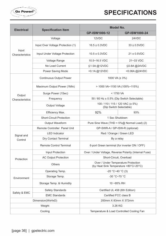
Electrical Specification ItemModel No.
GP-ISW1000-12 GP-ISW1000-24
InputCharacteristics
Voltage 12VDC 24VDC
Input Over Voltage Protection (1) 16.5 ± 0.3VDC 33 ± 0.5VDC
Input Under Voltage Protection 10.5 ± 0.3VDC 21 ± 0.5VDC
Voltage Range 10.5~16.5 VDC 21~33 VDC
No Load Current ≦1.5A @12VDC ≦0.8A @24VDC
Power Saving Mode <0.1A @12VDC <0.06A @24VDC
OutputCharacteristics
Continuous Output Power 1000 VA (± 3%)
Maximum Output Power (1Min) > 1000 VA~1150 VA (100%~115%)
Surge Power (1Sec) < 1750 VA
Frequency 50 / 60 Hz ± 0.5% (Dip Switch Selectable)
Output Voltage 100 / 110 / 115 / 120 VAC (± 5%)(Dip Switch Selectable)
Efficiency Max. 92% 93%
Short-Circuit Protection 1 Sec Shutdown
Output Waveform Pure Sine Wave (THD < 5%@ Normal Load) (2)
Signal and Control
Remote Controller Panel Unit GP-SWR-A / GP-ISW-R (optional)
LED Indicator Red / Orange / Green LED
Dry Contact Terminal By a relay
Remote Control Terminal 6-port Green terminal (for inverter ON / OFF)
Protection
Input Protection Over / Under Voltage, Reverse Polarity (Internal Fuse)
AC Output Protection Short-Circuit, Overload
Others Over / Under Temperature Protection(by Heat Sink Temperature +80°C/-20°C)
Environment
Operating Temp. -20 °C~40 °C (3)
Storage Temp. -30 °C~70 °C
Storage Temp. & Humidity 10 ~95% RH
Safety & EMCSafety Standards Certified UL 458 (6th Edition)
EMC Standards Certified FCC class B
Dimension(WxHxD) 200mm X 83mm X 372mm
Weight 3.26 KG
Cooling Temperature & Load Controlled Cooling Fan
SPECIFICATIONS

gpelectric.com | [page 37]
Electrical Specification ItemModel No.
GP-ISW1500-12 GP-ISW1500-24
InputCharacteristics
Voltage 12VDC 24VDC
Input Over Voltage Protection (1) 16.5 ± 0.3VDC 33 ± 0.5VDC
Input Under Voltage Protection 10.5 ± 0.3VDC 21 ± 0.5VDC
Voltage Range 10.5~16.5 VDC 21~33 VDC
No Load Current ≦1.8A @12VDC ≦1.0A @24VDC
Power Saving Mode <0.1A @12VDC <0.05A @24VDC
OutputCharacteristics
Continuous Output Power 1500 VA (± 3%)
Maximum Output Power (1Min) > 1500 VA~1730VA (100%~115%)
Surge Power (1Sec) <2650 VA
Frequency 50 / 60 Hz ± 0.5% (Dip Switch Selectable)
Output Voltage 100 / 110 / 115 / 120 VAC (± 5%)(Dip Switch Selectable)
Efficiency Max. 91% 92%
Short-Circuit Protection 1 Sec Shutdown
Output Waveform Pure Sine Wave (THD < 5%@ Normal Load) (2)
Signal and Control
Remote Controller Panel Unit GP-SWR-A / GP-ISW-R (optional)
LED Indicator Red / Orange / Green LED
Dry Contact Terminal By a relay
Remote Control Terminal 6-port Green terminal (for inverter ON / OFF)
Protection
Input Protection Over / Under Voltage, Reverse Polarity (Internal Fuse)
AC Output Protection Short-Circuit, Overload
Others Over / Under Temperature Protection(by Heat Sink Temperature +80°C/-20°C)
Environment
Operating Temp. -20 °C~40 °C (3)
Storage Temp. -30 °C~70 °C
Storage Temp. & Humidity 10 ~95% RH
Safety & EMCSafety Standards Certified UL 458 (6th Edition)
EMC Standards Certified FCC class B
Dimension(WxHxD) 248mm X 83mm X 421mm
Weight 4.14 KG
Cooling Temperature & Load Controlled Cooling Fan
SPECIFICATIONS
[page 38] | gpelectric.com
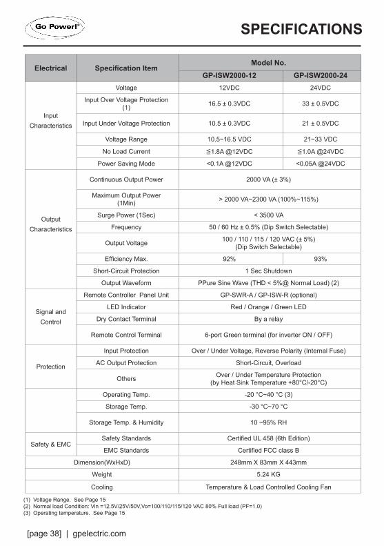
Electrical Specification ItemModel No.
GP-ISW2000-12 GP-ISW2000-24
InputCharacteristics
Voltage 12VDC 24VDC
Input Over Voltage Protection (1) 16.5 ± 0.3VDC 33 ± 0.5VDC
Input Under Voltage Protection 10.5 ± 0.3VDC 21 ± 0.5VDC
Voltage Range 10.5~16.5 VDC 21~33 VDC
No Load Current ≦1.8A @12VDC ≦1.0A @24VDC
Power Saving Mode <0.1A @12VDC <0.05A @24VDC
OutputCharacteristics
Continuous Output Power 2000 VA (± 3%)
Maximum Output Power (1Min) > 2000 VA~2300 VA (100%~115%)
Surge Power (1Sec) < 3500 VA
Frequency 50 / 60 Hz ± 0.5% (Dip Switch Selectable)
Output Voltage 100 / 110 / 115 / 120 VAC (± 5%)(Dip Switch Selectable)
Efficiency Max. 92% 93%
Short-Circuit Protection 1 Sec Shutdown
Output Waveform PPure Sine Wave (THD < 5%@ Normal Load) (2)
Signal and Control
Remote Controller Panel Unit GP-SWR-A / GP-ISW-R (optional)
LED Indicator Red / Orange / Green LED
Dry Contact Terminal By a relay
Remote Control Terminal 6-port Green terminal (for inverter ON / OFF)
Protection
Input Protection Over / Under Voltage, Reverse Polarity (Internal Fuse)
AC Output Protection Short-Circuit, Overload
Others Over / Under Temperature Protection(by Heat Sink Temperature +80°C/-20°C)
Operating Temp. -20 °C~40 °C (3)
Storage Temp. -30 °C~70 °C
Storage Temp. & Humidity 10 ~95% RH
Safety & EMCSafety Standards Certified UL 458 (6th Edition)
EMC Standards Certified FCC class B
Dimension(WxHxD) 248mm X 83mm X 443mm
Weight 5.24 KG
Cooling Temperature & Load Controlled Cooling Fan
SPECIFICATIONS
(1) Voltage Range. See Page 15(2) Normal load Condition: Vin =12.5V/25V/50V,Vo=100/110/115/120 VAC 80% Full load (PF=1.0)(3) Operating temperature. See Page 15
gpelectric.com | [page 39]
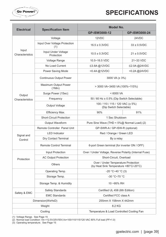
Electrical Specification ItemModel No.
GP-ISW3000-12 GP-ISW3000-24
InputCharacteristics
Voltage 12VDC 24VDC
Input Over Voltage Protection (1) 16.5 ± 0.3VDC 33 ± 0.5VDC
Input Under Voltage Protection 10.5 ± 0.3VDC 21 ± 0.5VDC
Voltage Range 10.5~16.5 VDC 21~33 VDC
No Load Current ≦3.8A @12VDC ≦2.0A @24VDC
Power Saving Mode <0.4A @12VDC <0.2A @24VDC
OutputCharacteristics
Continuous Output Power 3000 VA (± 3%)
Maximum Output Power (1Min) > 3000 VA~3450 VA (100%~115%)
Surge Power (1Sec) < 6000 VA
Frequency 50 / 60 Hz ± 0.5% (Dip Switch Selectable)
Output Voltage 100 / 110 / 115 / 120 VAC (± 5%)(Dip Switch Selectable)
Efficiency Max. 90% 91%
Short-Circuit Protection 1 Sec Shutdown
Output Waveform Pure Sine Wave (THD < 5%@ Normal Load) (2)
Signal and Control
Remote Controller Panel Unit GP-SWR-A / GP-ISW-R (optional)
LED Indicator Red / Orange / Green LED
Dry Contact Terminal By a relay
Remote Control Terminal 6-port Green terminal (for inverter ON / OFF)
Protection
Input Protection Over / Under Voltage, Reverse Polarity (Internal Fuse)
AC Output Protection Short-Circuit, Overload
Others Over / Under Temperature Protection(by Heat Sink Temperature +80°C/-20°C)
Operating Temp. -20 °C~40 °C (3)
Storage Temp. -30 °C~70 °C
Storage Temp. & Humidity 10 ~95% RH
Safety & EMCSafety Standards Certified UL 458 (6th Edition)
EMC Standards Certified FCC class A
Dimension(WxHxD) 255mm X 158mm X 442mm
Weight 8.2 KG
Cooling Temperature & Load Controlled Cooling Fan
SPECIFICATIONS
(1) Voltage Range. See Page 15(2) Normal load Condition: Vin =12.5V/25V/50V,Vo=100/110/115/120 VAC 80% Full load (PF=1.0)(3) Operating temperature. See Page 15
[page 40] | gpelectric.com
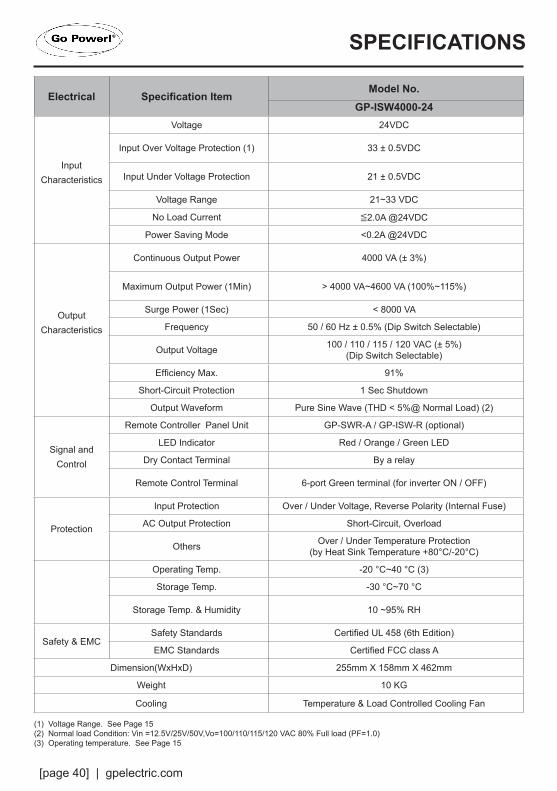
Electrical Specification ItemModel No.
GP-ISW4000-24
InputCharacteristics
Voltage 24VDC
Input Over Voltage Protection (1) 33 ± 0.5VDC
Input Under Voltage Protection 21 ± 0.5VDC
Voltage Range 21~33 VDC
No Load Current ≦2.0A @24VDC
Power Saving Mode <0.2A @24VDC
OutputCharacteristics
Continuous Output Power 4000 VA (± 3%)
Maximum Output Power (1Min) > 4000 VA~4600 VA (100%~115%)
Surge Power (1Sec) < 8000 VA
Frequency 50 / 60 Hz ± 0.5% (Dip Switch Selectable)
Output Voltage 100 / 110 / 115 / 120 VAC (± 5%)(Dip Switch Selectable)
Efficiency Max. 91%
Short-Circuit Protection 1 Sec Shutdown
Output Waveform Pure Sine Wave (THD < 5%@ Normal Load) (2)
Signal and Control
Remote Controller Panel Unit GP-SWR-A / GP-ISW-R (optional)
LED Indicator Red / Orange / Green LED
Dry Contact Terminal By a relay
Remote Control Terminal 6-port Green terminal (for inverter ON / OFF)
Protection
Input Protection Over / Under Voltage, Reverse Polarity (Internal Fuse)
AC Output Protection Short-Circuit, Overload
Others Over / Under Temperature Protection(by Heat Sink Temperature +80°C/-20°C)
Operating Temp. -20 °C~40 °C (3)
Storage Temp. -30 °C~70 °C
Storage Temp. & Humidity 10 ~95% RH
Safety & EMCSafety Standards Certified UL 458 (6th Edition)
EMC Standards Certified FCC class A
Dimension(WxHxD) 255mm X 158mm X 462mm
Weight 10 KG
Cooling Temperature & Load Controlled Cooling Fan
SPECIFICATIONS
(1) Voltage Range. See Page 15(2) Normal load Condition: Vin =12.5V/25V/50V,Vo=100/110/115/120 VAC 80% Full load (PF=1.0)(3) Operating temperature. See Page 15
gpelectric.com | [page 41]
7. END OF LIFE - RECYCLING
Product E.O.L (End of life) Information
This product required the extraction and use of natural resources. It may contain substances that could be harmful to the environment or human health if improperly handled at the product’s end of life. In order to avoid release of such substances into the environment and to reduce the use of natural resources, we encourage you to recycle the GP-ISW in an appropriate way that will ensure most of the materials are reused or recycled appropriately.
DO NOT DISPOSE OF THIS PRODUCT WITH NORMAL GARBAGE
The easiest way to recycle the GP-ISW is to take the unit to a local certified e-waste (electronics waste) recycling centre. Knowing for sure if your appliances are being recycled properly is tricky. If you’re in doubt just ask. Recyclers that are certified should gladly show you their certification. If the re-cycler is certified, chances are very high that they are recycling responsibly.
To find your local e-waste centre please contact your local municipality. The following website also has information on local recycling centres: www.earth911.com/recycling-center-search-guides
If you have no local certified e-waste recycling centre, the GP-ISW can be dis-assembled manually and recycled responsibly. A Phillips screwdriver is required to disassemble the GP-ISW. Note: The GP-ISW should only be disassembled at the end of its service life. Go Power! provides no spare parts for the GP-ISW.
www.earth911.com/recycling-center-search-guidesLocal recycling centres can be found here;Corporate Social Responsibility
Carmanah Technologies

© 2016 Go Power!® By Carmanah Technologies
Worldwide Technical Support and Product Information gpelectric.com
Carmanah Technologies Corporate Headquarters250 Bay St, Victoria, BC Canada V9A 3K5Tel: 1.866.247.6527
78158_MAN_ISW_RevC